WO2017187931A1 - 運転支援装置及びセンタ - Google Patents
運転支援装置及びセンタ Download PDFInfo
- Publication number
- WO2017187931A1 WO2017187931A1 PCT/JP2017/014469 JP2017014469W WO2017187931A1 WO 2017187931 A1 WO2017187931 A1 WO 2017187931A1 JP 2017014469 W JP2017014469 W JP 2017014469W WO 2017187931 A1 WO2017187931 A1 WO 2017187931A1
- Authority
- WO
- WIPO (PCT)
- Prior art keywords
- vehicle
- distance
- unit
- intersection
- information
- Prior art date
- Legal status (The legal status is an assumption and is not a legal conclusion. Google has not performed a legal analysis and makes no representation as to the accuracy of the status listed.)
- Ceased
Links
Images
Classifications
-
- B—PERFORMING OPERATIONS; TRANSPORTING
- B60—VEHICLES IN GENERAL
- B60Q—ARRANGEMENT OF SIGNALLING OR LIGHTING DEVICES, THE MOUNTING OR SUPPORTING THEREOF OR CIRCUITS THEREFOR, FOR VEHICLES IN GENERAL
- B60Q1/00—Arrangement of optical signalling or lighting devices, the mounting or supporting thereof or circuits therefor
- B60Q1/26—Arrangement of optical signalling or lighting devices, the mounting or supporting thereof or circuits therefor the devices being primarily intended to indicate the vehicle, or parts thereof, or to give signals, to other traffic
- B60Q1/34—Arrangement of optical signalling or lighting devices, the mounting or supporting thereof or circuits therefor the devices being primarily intended to indicate the vehicle, or parts thereof, or to give signals, to other traffic for indicating change of drive direction
- B60Q1/346—Arrangement of optical signalling or lighting devices, the mounting or supporting thereof or circuits therefor the devices being primarily intended to indicate the vehicle, or parts thereof, or to give signals, to other traffic for indicating change of drive direction with automatic actuation
-
- B—PERFORMING OPERATIONS; TRANSPORTING
- B60—VEHICLES IN GENERAL
- B60Q—ARRANGEMENT OF SIGNALLING OR LIGHTING DEVICES, THE MOUNTING OR SUPPORTING THEREOF OR CIRCUITS THEREFOR, FOR VEHICLES IN GENERAL
- B60Q1/00—Arrangement of optical signalling or lighting devices, the mounting or supporting thereof or circuits therefor
- B60Q1/26—Arrangement of optical signalling or lighting devices, the mounting or supporting thereof or circuits therefor the devices being primarily intended to indicate the vehicle, or parts thereof, or to give signals, to other traffic
- B60Q1/34—Arrangement of optical signalling or lighting devices, the mounting or supporting thereof or circuits therefor the devices being primarily intended to indicate the vehicle, or parts thereof, or to give signals, to other traffic for indicating change of drive direction
Definitions
- the present disclosure relates to a driving support device and a center that support driving of a vehicle.
- Patent Document 1 discloses a technique for controlling the timing for informing the surroundings of the direction of the vehicle's right / left turn.
- 30 m before the guidance intersection is set as a recommended point where the direction indicator should be turned on. And even if the direction indicator switch is operated before this recommended point, the direction indicator is not lit until the recommended point is reached, and the direction indicator is lit when the recommended point is reached. . If there is an approach path in the direction corresponding to the lighting instruction signal input via the direction indicator switch between the recommended point and the guidance intersection, the direction indicator will proceed after the process proceeds until there is no such approach path. Lights up.
- the recommended point is uniformly determined by the distance from the intersection.
- the appropriate timing at which the direction indicator should be turned on is different depending on the individual intersection approach path, which is less likely to cause confusion in the surroundings.
- the present disclosure has been made in view of the above-described conventional problems, and the purpose of the present disclosure is to make the timing for informing the direction of the vehicle's right / left turn to the surroundings less likely to cause confusion in the surroundings.
- a driving support apparatus is used in a vehicle and starts a position acquisition unit that acquires the position of the host vehicle, a map data acquisition unit that acquires map data, and an operation of a direction indicator in front of an intersection.
- the distance acquisition unit that acquires the operation start distance information indicating the operation start distance for each approach road, the position of the vehicle acquired by the position acquisition unit, the map data acquired by the map data acquisition unit, and the distance acquisition unit Using the acquired operation start distance information, the distance specifying unit that specifies the operation start distance on the intersection approach road where the vehicle is located, and the operation specified by the distance specifying unit when the vehicle makes a right or left turn at the intersection
- a direction indication support unit that provides support so that the operation of the direction indicator of the host vehicle is started at the start distance.
- the operation start distance at which the operation of the direction indicator should be started before the intersection on the approach path is specified. Therefore, the distance at which the operation of the direction indicator should be started before the intersection can be specified for each intersection approach path.
- the direction indication support unit provides support so that the operation of the direction indicator of the own vehicle is started at the specified operation start distance, so that it is difficult for the surroundings to be confused according to each intersection approach path. It is possible to turn on the direction indicator at an appropriate timing. As a result, the timing for notifying the surroundings of the direction of the vehicle's right or left turn can be set to a timing that is less likely to cause confusion in the surroundings.
- the center transmits a plurality of vehicles, and when the vehicle makes a right or left turn at the intersection, the driver of the vehicle operates the direction indicator in front of the intersection.
- the direction indicator in front of the intersection is obtained by collecting the indicator-related information including the distance from which the vehicle started and the indicator-related information obtained from multiple vehicles in the collector by statistics for each approach road
- the creation unit that creates the operation start distance information that shows the operation start distance for each intersection approach path that should start the operation of the vessel, and the operation start distance information created by the creation unit
- a distribution unit that transmits the information to the vehicle that supports the operation so that the operation of the direction indicator is started at the operation start distance on the intersection approach road where the vehicle is located using the operation start distance information.
- the operation start distance at which the operation of the direction indicator should be started before the intersection is entered. Since the operation start distance information shown for each road is created, it is possible to create the operation start distance information along the tendency of drivers of a plurality of vehicles. And since this operation start distance information is transmitted from a delivery part to a vehicle, in this vehicle, operation of a direction indicator starts with the operation start distance along the tendency of drivers of a plurality of vehicles on an intersection approach road where the vehicle is located. It will be possible to provide support in the same way.
- the timing for notifying the surroundings of the direction of the vehicle's right or left turn can be set to a timing that is less likely to cause confusion in the surroundings.
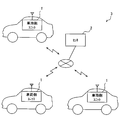
- FIG. 1 is a diagram illustrating an example of a schematic configuration of a driving support system
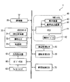
- FIG. 2 is a diagram illustrating an example of a schematic configuration of the vehicle-side unit.
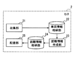
- FIG. 3 is a diagram showing an example of a schematic configuration of the center.
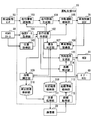
- FIG. 4 is a diagram illustrating an example of a schematic configuration of the driving assistance ECU.
- FIG. 5 is a flowchart illustrating an example of a flow of distance measurement related processing in the distance measurement unit
- FIG. 6 is a flowchart illustrating an example of a flow of support-related processing in the driving support ECU.
- FIG. 7 is a diagram illustrating an example of a schematic configuration of the driving assistance ECU.
- FIG. 8 is a diagram illustrating an example of a schematic configuration of the center.
- the driving support system 3 includes a vehicle-side unit 1 and a center 2 that are used for each of a plurality of vehicles.
- the vehicle-side unit 1 is used for a vehicle that performs automatic driving for automatically controlling acceleration, braking, and steering, and communicates with the center 2.
- the center 2 is a server device, for example, and collects information transmitted from each vehicle-side unit 1 mounted on a plurality of vehicles, or creates information created based on the collected information for each vehicle-side unit 1. Or send to.
- the center 2 may be composed of a single server device or may be composed of a plurality of server devices.
- the vehicle-side unit 1 is used for an autonomous driving vehicle.
- the vehicle-side unit 1 includes a driving assistance ECU 10, a communication device 20, an ADAS (Advanced Driver Assistance Systems) locator 30, an HMI (Human Machine Interface) system 40, A periphery monitoring sensor 50, a body ECU 60, a direction indicator 61, a winker switch 62, and a vehicle control ECU 70 are included.
- the driving support ECU 10, the communication device 20, the ADAS locator 30, the HMI system 40, the body ECU 60, and the vehicle control ECU 70 are connected to, for example, an in-vehicle LAN, and can exchange information with each other by communication.
- the communication device 20 communicates with the center 2.
- the communication device 20 may be configured to communicate with the center 2 using a communication module for performing communication via a public communication network such as a mobile phone network or the Internet.
- a communication module for telematics communication such as DCM (Data Communication Module) may be configured to communicate with the center 2 via a communication network used for telematics communication.
- the communication device 20 outputs information downloaded from the center 2 to the in-vehicle LAN, and uploads information transmitted from the driving support ECU 10 to the center 2 through the in-vehicle LAN.
- the communication device 20 may be configured to communicate with the center 2 via a roadside device.
- the ADAS locator 30 includes a GNSS (Global Navigation Satellite System) receiver 31, an inertial sensor 32, and a map database (hereinafter referred to as DB) 33 storing map data.
- the GNSS receiver 31 receives positioning signals from a plurality of artificial satellites.
- the inertial sensor 32 includes, for example, a triaxial gyro sensor and a triaxial acceleration sensor.
- the map DB 33 is a nonvolatile memory, and stores map data such as link data, node data, road shapes, and structures.
- Link data includes a unique number (link ID) that identifies the link, link length indicating the link length, link direction, link shape information, node coordinates (latitude / longitude) of the start and end of the link, and connection to the node Connection link IDs in which link IDs of all links to be described are described, link attributes describing whether each link connected to a node is an incoming link or an outgoing link, and road attribute data Consists of The road attributes include road name, road type, road width, number of lanes, speed regulation value, and the like.
- the node data includes a node ID, a node coordinate, a node name, a node type, a link ID of a link connected to the node, an intersection type, etc. Composed of each data.
- the ADAS locator 30 sequentially measures the vehicle position of the vehicle on which the ADAS locator 30 is mounted by combining the positioning signal received by the GNSS receiver 31 and the measurement result of the inertial sensor 32. In addition, it is good also as a structure which uses the travel distance calculated
- the ADAS locator 30 also reads map data from the map DB 33 and outputs it to the in-vehicle LAN. The map data may be obtained from the outside of the vehicle using a communication module.
- the HMI system 40 includes an HCU (Human Machine Interface Control Unit) 41, an operation device 42, a display device 43, and an audio output device 44, as shown in FIG.
- the HMI system receives an input operation from the driver of the own vehicle or presents information to the driver of the own vehicle.
- the operation device 42 is a group of switches operated by the driver of the own vehicle.
- the operation device 42 is used for performing various settings.
- the operation device 42 there are a steering switch provided in a spoke spoke portion of the own vehicle, a touch switch integrated with the display device 43, and the like.
- the display device 43 presents information by displaying text and / or images. Examples of the display device 43 include a combination meter, CID (Center Information Display), and HUD (Head-Up Display).
- the audio output device presents information by outputting audio. Examples of the audio output device 44 include an audio speaker.
- the HCU 41 includes a CPU, a volatile memory, a nonvolatile memory, an I / O, and a bus for connecting them, and executes various processes by executing a control program stored in the nonvolatile memory.
- the HCU 41 causes the display device 43 and / or the audio output device 44 to present information in accordance with an instruction from the driving support ECU 10. Information presentation at the HCU 41 will be described in detail later.
- the periphery monitoring sensor 50 detects obstacles such as moving objects such as pedestrians, animals other than humans, bicycles, motorcycles, and other vehicles, and falling objects on the road, guardrails, curbs, and stationary objects such as trees. In addition, road markings such as travel lane markings and stop lines are detected.
- the peripheral monitoring sensor 50 is, for example, a peripheral monitoring camera that captures a predetermined range around the host vehicle, a millimeter wave radar that transmits an exploration wave to the predetermined range around the host vehicle, sonar, LIDAR (Light Detection and Ranging / Laser Imaging Detect ion and Ranging). The peripheral monitoring camera sequentially outputs captured images that are sequentially captured to the peripheral monitoring ECU 51 as sensing information.
- a sensor that transmits an exploration wave such as sonar, millimeter wave radar, or LIDAR sequentially outputs a scanning result based on a reception signal obtained when a reflected wave reflected by an obstacle is received to the driving support ECU 10 as sensing information.
- the direction indicator 61 is a so-called blinker, and transmits a direction in which the host vehicle changes its direction to the surroundings by turning on one of the left and right lamps.
- the winker switch 62 is a switch for detecting an operation of a winker lever that is an operation member for performing a lamp lighting operation of the direction indicator 61, and turns right or left in accordance with an operation of the winker lever (hereinafter, winker operation). Outputs the hour signal.
- the body ECU 60 is an electronic control device that controls electrical components such as the direction indicator 61. For example, the body ECU 60 executes control to turn on the lamp of the direction indicator 61 in accordance with the winker signal input from the winker switch 62. The body ECU 60 can output this blinker signal to the in-vehicle LAN.
- the vehicle control ECU 70 is an electronic control device that performs acceleration / deceleration control and / or steering control of the host vehicle.
- the vehicle control ECU 70 includes a steering ECU that performs steering control, a power unit control ECU that performs acceleration / deceleration control, a brake ECU, and the like.
- the vehicle control ECU 70 acquires detection signals output from sensors such as an accelerator position sensor, a brake pedal force sensor, a rudder angle sensor, and a wheel speed sensor mounted on the host vehicle, and performs electronic control throttle, brake actuator, EPS (Electric Power Steering) Outputs control signals to each travel control device such as a motor. Further, the vehicle control ECU 70 can output the detection signals of the above-described sensors to the in-vehicle LAN.
- the driving support ECU 10 includes a CPU, a volatile memory, a non-volatile memory, an I / O, and a bus for connecting them, and executes various processes by executing a control program stored in the non-volatile memory.
- the driving assistance ECU 10 recognizes the traveling environment of the vehicle from the sensing result of the surrounding monitoring sensor 50.
- the driving assistance ECU 10 controls the vehicle control ECU 70 to perform a driving operation by the driver.
- the driving assistance ECU 10 causes the communication device 20 to upload information related to the winker operation by the driver (hereinafter referred to as instruction-related information) from the communication device 20 to the center 2 when the host vehicle makes a right or left turn.
- the instruction-related information includes the intersection approach path (that is, the approach link) when the vehicle makes a right or left turn at the intersection, and the distance at which the driver of the vehicle starts the lamp operation of the direction indicator before the intersection ( Hereinafter, the actual operation distance) and a time stamp indicating the time when the actual operation distance was measured are included.
- the approach link information for example, a configuration using the link ID of the approach link may be used.
- the driving assistance ECU 10 executes processing related to operation assistance of the direction indicator 61.
- This driving support ECU 10 corresponds to a driving support device. The processing in the driving support ECU 10 will be described in detail later. Note that some or all of the functions executed by the driving support ECU 10 may be configured in hardware by one or a plurality of ICs.
- the center 2 is a server device, for example, and includes a collection unit 21, a vehicle information storage unit 22, a distance information creation unit 23, a distance information storage unit 24, and a distribution unit 25, as shown in FIG. Yes.
- the collection unit 21 acquires information uploaded from the vehicle-side unit 1.
- the collection unit 21 stores the above-described instruction-related information uploaded from the vehicle-side unit 1 mounted on each of the plurality of vehicles in the vehicle information storage unit 22, whereby the instruction-related information about the plurality of vehicles is stored. Collect information.
- the vehicle information storage unit 22 may be configured to use an electrically readable and writable nonvolatile memory.
- the instruction-related information may be stored in the vehicle information storage unit 22 in association with the actual operation distance and the time stamp indicating the time when the actual operation distance is measured for each approach link. If the memory capacity of the vehicle information storage unit 22 is exceeded, the old information may be sequentially deleted based on the time stamp.
- the distance information creation unit 23 stats the actual operation distance stored in the vehicle information storage unit 22 for each approach link, and calculates a representative value of the actual operation distance for each approach link, thereby calculating the actual operation distance for each approach link. Create a representative value for. Examples of the representative value include an average value, a median value, and a mode value. Note that the unit of the actual operation distance in calculating the representative value is not limited to, for example, 1 m units, and may be 5 m units, 10 m units, or the like.
- the distance information creating unit 23 stores the created representative value of the actual operation distance for each approach link in the distance information storage unit 24 for each approach link.
- the link ID of the approach link and the representative value of the actual operation distance may be stored in association with each other.
- the information on the representative value of the actual operation distance for each approach link is hereinafter referred to as operation start distance information.
- the distance information storage unit 24 may be configured to use an electrically readable and writable nonvolatile memory. This distance information creation unit 23 corresponds to a creation unit.
- the distribution unit 25 transmits the operation start distance information stored in the distance information storage unit 24 to the vehicle-side unit 1.
- the operation start distance information may be transmitted to the vehicle side unit 1 that has requested transmission of the operation start distance information.
- the vehicle position is transmitted from the vehicle-side unit 1 in order to reduce the communication amount, and the distribution unit 25 starts an operation within a predetermined range around the vehicle on which the vehicle-side unit 1 is mounted based on the vehicle position. What is necessary is just to set it as the structure which transmits distance information.
- the predetermined range for example, within a radius of several kilometers, within a mesh to which the vehicle position belongs, and the like can be mentioned.
- the distribution unit 25 transmits the operation start distance information to the roadside machine connected to the center 2 through the communication network, and the operation start distance information from the roadside machine to the vehicle side unit 1 located within the communication range of the roadside machine. May be configured to transmit. In this case, the distribution unit 25 may transmit the operation start distance information within a predetermined range (for example, within a radius of several kilometers) around the installation position of the roadside machine.
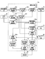
- the driving assistance ECU 10 includes a position acquisition unit 100, a map data acquisition unit 101, a travel position identification unit 102, a travel environment recognition unit 103, a travel plan generation unit 104, an automatic driving function unit 105, and vehicle information acquisition.
- Unit 106, superiority determination unit 107, determination result storage unit 108, distance measurement unit 109, measurement result storage unit 110, transmission processing unit 111, distance acquisition unit 112, distance information storage unit 113, distance identification unit 114, and direction indication support Part 115 is provided.
- the position acquisition unit 100 acquires the vehicle position of the host vehicle output from the ADAS locator 30.
- the map data acquisition unit 101 acquires map data output from the ADAS locator 30.
- the travel position specifying unit 102 specifies the vehicle position of the host vehicle on the map from the vehicle position of the own vehicle acquired by the position acquisition unit 100 and the map data acquired by the map data acquisition unit 101.
- the travel environment recognition unit 103 recognizes the travel environment of the host vehicle from the vehicle position and map data of the host vehicle used in the travel position specifying unit 102, sensing information acquired from the surrounding monitoring sensor 50, and the like. As an example, the traveling environment recognition unit 103 recognizes the shape and movement state of an object around the host vehicle from the sensing information acquired from the surrounding monitoring sensor 50 within the sensing range of the surrounding monitoring sensor 50, and actually travels. Generate a virtual space that reproduces the environment. In addition, the traveling environment recognition unit 103 recognizes the traveling environment using map data outside the sensing range of the periphery monitoring sensor 50.
- the travel plan generation unit 104 generates a travel plan for driving the vehicle by automatic driving.
- the travel plan generated by the travel plan generation unit 104 is output to the automatic driving function unit 105.
- the travel plan generation unit 104 uses the vehicle position and map data of the host vehicle used by the travel position specifying unit 102 to generate a recommended route for directing the host vehicle to the destination as a medium to long-term travel plan.
- the recommended route may be configured to search using the Dijkstra method by setting a link cost so that, for example, a road suitable for running by automatic driving is prioritized.
- the travel plan generation unit 104 generates a short-term travel plan for traveling according to the recommended route, using the virtual space around the vehicle generated by the travel environment recognition unit 103. As a specific example, execution of steering for lane change, acceleration / deceleration for speed adjustment, steering and braking for obstacle avoidance, and the like is determined.
- the automatic driving function unit 105 substitutes the driving operation by the driver by causing the vehicle control ECU 70 to automatically perform acceleration, braking, and / or steering of the vehicle according to the driving plan output from the driving plan generation unit 104. Do.
- This function of performing the driving operation is called an automatic driving function.
- the automatic driving function there is an ACC (Adaptive Cruise Control) function that controls the traveling speed of the own vehicle so as to maintain the target inter-vehicle distance from the preceding vehicle by adjusting the driving force and the braking force.
- ACC Adaptive Cruise Control
- LKA Lane Keeping Assist
- LCA Longe Change Assist
- AEB Automatic Emergency Braking
- an automatic driving function a function for performing acceleration / deceleration and steering so that the vehicle position of the vehicle travels along the recommended route generated by the travel plan generation unit 104, and travel along a recommended travel locus
- a function of performing acceleration / deceleration and steering and a function of automatically stopping on a road shoulder or the like in an emergency.
- operation function it is assumed that the own vehicle automatically makes a right / left turn at an intersection by an automatic driving function.
- the automatic driving function unit 105 can switch execution / non-execution of automatic driving.
- the failure to perform automatic driving means that the driver operates all the main control systems such as the brake, steering, throttle, and driving force of the vehicle without performing automation. That is, manual operation.
- the automatic driving function unit 105 may be switched so as not to perform the automatic driving according to an input operation by the driver to the operation device 42, for example.
- the vehicle information acquisition unit 106 acquires a state quantity related to the behavior of the host vehicle from the detection result of each sensor output via the vehicle control ECU 70.
- vehicle information such as the vehicle speed, travel distance, yaw rate, and steering angle of the host vehicle is acquired.
- This vehicle information corresponds to driving operation information, and this vehicle information acquisition unit 106 corresponds to a driving operation acquisition unit.
- the vehicle information acquisition unit 106 may be configured to acquire detection signals from the sensors without using the vehicle control ECU 70.
- the superiority determination unit 107 includes the vehicle information acquired by the vehicle information acquisition unit 106, the vehicle position and map data of the host vehicle used by the travel position specifying unit 102, and the vehicle position of the host vehicle on the map specified by the travel position specifying unit 102. Etc. to determine whether or not the driver of the vehicle is a good driver that complies with traffic regulations.
- This quality determination unit 107 corresponds to a vehicle side quality determination unit. Specifically, it is determined whether or not the driver is a good driver by using as an index the ability to comply with the stop at the place where the vehicle is temporarily stopped, the compliance with the speed limit, the appropriateness of the inter-vehicle distance, the frequency of lane changes, and the like. An example is described below.
- the quality determination unit 107 stores the determination result in the determination result storage unit 108 in association with a time stamp indicating the determined time (hereinafter simply referred to as determination time).
- the determination result storage unit 108 may be configured to use an electrically readable and writable nonvolatile memory.
- the superiority determination unit 107 determines that the driver is an excellent driver when the determination results for the most recent predetermined number of times stored in the determination result storage unit 108 are determination results indicating that the vehicle has stopped before the stop line. On the other hand, if this condition is not satisfied, it is determined that the driver is not a good driver.
- the predetermined number here is a value that can be arbitrarily set, and may be one time. However, in order to further improve the determination accuracy, it is preferably a plurality of times. In addition, it is good also as a structure determined as a good driver
- the vehicle position of the vehicle on the map that is sequentially specified by the travel position specifying unit 102, the speed regulation value in the map data, and the vehicle information acquisition unit 106 are sequentially acquired. Based on the vehicle speed of the vehicle information to be determined, it is determined whether the speed limit value of the link where the vehicle is located exceeds a predetermined value or more.
- the predetermined value here is a value that can be arbitrarily set.
- the superiority determination unit 107 associates the determination result with the determination time, stores the determination result in the determination result storage unit 108, and determines whether or not the driver is a good driver in the same manner as in the case where the suspension compliance is used as an index. Note that it may be configured to determine whether or not the driver is a good driver based on a determination result of whether or not the vehicle speed of the surrounding vehicle recognized by the traveling environment recognition unit 103 exceeds a predetermined value or more.
- the inter-vehicle distance between the preceding vehicle and the host vehicle that are sequentially recognized by the traveling environment recognition unit 103 and the vehicle information among the vehicle information sequentially acquired by the vehicle information acquisition unit 106 Based on the vehicle speed, it is determined whether or not the target inter-vehicle distance corresponding to the vehicle speed of the host vehicle is less than a predetermined value.
- the target inter-vehicle distance corresponding to the vehicle speed may be the same as that set by the ACC function or the like.
- the superiority determination unit 107 associates the determination result with the determination time, stores the determination result in the determination result storage unit 108, and determines whether or not the driver is a good driver in the same manner as in the case where the suspension compliance is used as an index.
- the frequency of lane change within a predetermined distance is set as a threshold based on the travel distance and steering angle of the vehicle in the vehicle information sequentially acquired by the vehicle information acquisition unit 106. It is determined whether or not it exceeds. As an example, it may be determined whether or not the frequency of lane change within a few hundred meters is four times or more. The presence or absence of a lane change may be determined based on the change in the steering angle. In addition to the change in the steering angle, the determination may be based on the change in the yaw rate. If the vehicle position on the map can be specified for each lane, the change in the vehicle position is used. You may judge.
- the superiority determination unit 107 associates the determination result with the determination time, stores the determination result in the determination result storage unit 108, and determines whether or not the driver is a good driver in the same manner as in the case where the suspension compliance is used as an index.
- the goodness determination unit 107 may be configured to determine whether or not the driver is a good driver based on one of the above-described indexes, or may determine whether or not the driver is a good driver based on a plurality of indexes. It is good also as a structure.
- the configuration may be such that the driver is determined to be a good driver when the conditions are satisfied for all of the plurality of indicators.
- a configuration may be adopted in which a good driver is determined when the above conditions are satisfied.
- the distance measurement unit 109 starts the operation of the direction indicator in front of the intersection when the vehicle makes a right or left turn at the intersection only when the excellent determination unit 107 determines that the driver is an excellent driver.
- the measured distance (that is, the actual operation distance) is measured.
- the distance measurement unit 109 includes the vehicle position of the vehicle on the map that is sequentially identified by the travel position identifying unit 102, the travel distance of the vehicle in the vehicle information that is sequentially acquired by the vehicle information acquisition unit 106, and the body ECU 60.
- the actual operation distance is measured based on the winker signal that is sequentially acquired via the. Details of the measurement of the actual operation distance will be described later.
- the distance measuring unit 109 associates the measured actual operation distance of the own vehicle with a time stamp indicating the measurement time (hereinafter simply referred to as measurement time) and the link ID of the approach link at the time of turning left and right, and the measurement result storage unit 110.
- the measurement result storage unit 110 may be configured to use an electrically readable / writable nonvolatile memory, but in the first embodiment, a configuration using a volatile memory such as a RAM.
- the structure which measures an actual operation distance only here when the excellent determination part 107 determines with a good driver was shown, it does not necessarily restrict to this.
- the actual operation distance may be stored in the measurement result storage unit 110 only when the excellent determination unit 107 determines that the driver is a good driver.
- the transmission processing unit 111 reads out the actual operation distance stored in the measurement result storage unit 110, the measurement time and the link ID associated with the actual operation distance, and outputs them to the communication device 20.
- the communication device 20 generates a packet including the actual operation distance, the measurement time, and the link ID input from the transmission processing unit 111 and uploads the packet to the center 2. This packet corresponds to the instruction-related information described above.
- the uploading of the instruction related information from the communication device 20 to the center 2 may be performed by receiving power supply from the backup power source when the ignition power source of the own vehicle is turned off, for example.
- the uploading of the instruction related information from the communication device 20 to the center 2 may be performed periodically.
- the measurement result storage unit 110 may be configured to sequentially delete information read from the transmission processing unit 111.
- the representative value of the actual operation distance for each approach link Will be created.
- the communication device 20 downloads information on the representative value of the actual operation distance for each approach link (that is, operation start distance information).
- the timing at which the communication device 20 downloads the operation start distance information may be periodic, or may be when a predetermined trigger occurs such as when the ignition power of the host vehicle is turned on.
- uploading to the center 2 is performed with the actual operation distance of the driver determined as the excellent driver by the excellent determination unit 107 being narrowed down. Therefore, in the center 2, a representative value of the actual operation distance for the excellent driver is created. And the communication apparatus 20 downloads the operation start distance information about a good driver.
- the distance acquisition unit 112 acquires the operation start distance information downloaded by the communication device 20 from the center 2.
- the distance acquisition unit 112 stores the acquired operation start distance information in the distance information storage unit 113.
- the distance information storage unit 113 may be configured to use an electrically readable / writable nonvolatile memory, or may be configured to use a volatile memory.
- the distance specifying unit 114 uses the vehicle position of the vehicle on the map sequentially specified by the travel position specifying unit 102 and the operation start distance information stored in the distance information storage unit 113 to locate the vehicle.
- the operation start distance at which the operation of the direction indicator 61 should be started before the intersection is specified.
- the distance specifying unit 114 extracts the representative value of the actual operation distance associated with the link ID of the approach link where the vehicle is located, from the operation start distance information stored in the distance information storage unit 113. The extracted representative value is specified as the operation start distance.
- the direction indication support unit 115 provides support so that the operation of the direction indicator 61 of the own vehicle is started at the operation start distance specified by the distance specifying unit 114 when the own vehicle makes a right or left turn at an intersection. Whether the own vehicle makes a right or left turn at an intersection may be determined based on the recommended route generated by the travel plan generation unit 104 if the vehicle is traveling by automatic driving, for example. If the vehicle is traveling by manual driving, it may be determined based on whether the vehicle is located in the right turn lane, the vehicle is located in the left turn lane, the recommended route searched by the navigation function, or the like. Details of support in the direction instruction support unit 115 will be described later.
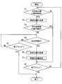
- the flowchart in FIG. 5 may be configured to be started when, for example, the ignition power of the own vehicle is turned on and when the excellent determination unit 107 determines that the driver is a good driver.
- step S1 on-operation of the direction indicator 61 for turning on the lamp of the direction indicator 61 is detected based on the winker signal acquired through the body ECU 60. Specifically, an on operation is detected when the blinker signal is on. If an on operation is detected (YES in S1), the process proceeds to step S2. On the other hand, when the on operation is not detected (NO in S1), the process proceeds to step S8.
- step S2 the vehicle position of the latest vehicle on the map specified by the travel position specifying unit 102 is acquired.
- the vehicle position of the host vehicle acquired in S2 is referred to as a vehicle position P1.
- the vehicle position of the latest own vehicle acquired by the position acquisition unit 100 may be acquired.
- step S3 an off operation for turning off the lamp of the direction indicator 61 is detected based on the winker signal acquired through the body ECU 60. Specifically, an off operation is detected when the winker signal is off. If an off operation is detected (YES in S3), the process proceeds to step S8. On the other hand, when the off operation is not detected (NO in S1), the process proceeds to step S4.
- step S4 a left / right turn at the intersection of the vehicle is detected.
- the vehicle enters the intersection based on the vehicle position of the vehicle on the map that is sequentially identified by the travel position identifying unit 102, and exits to the exit link that intersects the entrance link, What is necessary is just to detect the left-right turn at the intersection of the own vehicle.
- the amount of change in the steering angle or yaw rate of the vehicle in the vehicle information sequentially acquired by the vehicle information acquisition unit 106 is also used, the vehicle enters the intersection, and the amount of change in the steering angle or yaw rate is a threshold value. When it becomes above, it is good also as a structure which detects the left-right turn in the intersection of the own vehicle.
- step S5 when the right-left turn in the intersection of the own vehicle is not detected (it is NO at S4), it moves to step S5. On the other hand, when a right / left turn at the intersection of the own vehicle is detected (YES in S4), the process proceeds to step S6.
- step S5 when it is the end timing of the distance measurement related process (YES in S5), the distance measurement related process is ended. On the other hand, if it is not the end timing of the distance measurement related process (NO in S5), the process returns to step S4 and the process is repeated.
- the end timing of the distance measurement related processing for example, when the ignition power of the own vehicle is turned off.
- step S6 when a left or right turn at the intersection of the own vehicle is detected in S4, the vehicle position of the latest own vehicle on the map specified by the travel position specifying unit 102 is acquired.
- the vehicle position of the own vehicle acquired in S6 is referred to as a vehicle position P2.
- step S7 a linear distance from the vehicle position P1 acquired in S2 to the vehicle position P2 acquired in S6 is calculated, and the calculated distance is measured as an actual operation distance.
- step S8 in the same manner as in S5, when it is the end timing of the distance measurement related process (YES in S8), the distance measurement related process is ended. On the other hand, if it is not the end timing of the distance measurement related process (NO in S8), the process returns to step S1 and the process is repeated.
- the actual operation distance is measured from the vehicle position when the on operation for turning on the lamp of the direction indicator 61 is detected and the vehicle position when the right or left turn at the intersection is detected.
- the present invention is not limited to this.
- the actual operation distance may be measured from the travel distance of the own vehicle from when the on operation for turning on the lamp of the direction indicator 61 is detected to when the right or left turn at the intersection is detected.
- the travel distance of the host vehicle may be obtained from a pulse signal of a wheel speed sensor, or may be obtained from an odometer.
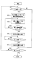
- FIG. 6 the case where the own vehicle automatically makes a right / left turn at an intersection by an automatic driving function will be described as an example.
- FIG. 6 the operation start distance information downloaded from the center 2 will be described as having been acquired by the driving support ECU 10.
- the flowchart in FIG. 6 may be configured to start when an automatic operation including an automatic operation function for automatically making a right / left turn at an intersection is started.
- step S21 if the vehicle is scheduled to make a right or left turn at the nearest intersection in front of the course of the vehicle (hereinafter, the target intersection) (YES in S21), the process proceeds to step S22. On the other hand, if it is not planned to make a right or left turn (NO in S21), the process proceeds to step S28.
- whether or not the vehicle is scheduled to make a right or left turn at the target intersection is determined based on the recommended route generated by the travel plan generation unit 104 and the vehicle position of the vehicle on the map specified by the travel position specification unit 102.
- the distance specifying unit 114 may determine from the above.
- step S22 the distance specifying unit 114 specifies the operation start distance for the target intersection from the operation start distance information stored in the distance information storage unit 113 as described above.
- step S ⁇ b> 23 the direction instruction support unit 115 calculates the distance to the target intersection from the vehicle position of the host vehicle on the map specified by the travel position specifying unit 102 and the position of the target intersection on the map. What is necessary is just to set it as the structure which uses the coordinate of the representative point of an intersection as a position of the object intersection said here.
- the representative point of the intersection may be the center of the intersection, for example.
- step S24 the direction instruction support unit 115 has reached the operation start distance from the own vehicle to the target intersection based on the operation start distance specified in S22 and the distance from the own vehicle to the target intersection calculated in S23. It is determined whether or not. If it is determined that the operation start distance has been reached (YES in S24), the process proceeds to step S25. On the other hand, if it is determined that the operation start distance has not been reached (NO in S24), the process of S24 is repeated.
- step S25 the direction instruction support unit 115 sends an instruction to the body ECU 60 to execute control to turn on the lamp of the direction indicator 61.
- the direction instruction support unit 115 sends an instruction to turn on the lamp in the direction corresponding to the result of determining whether the vehicle is scheduled to make a right or left turn in S21.
- the lamp of the direction indicator 61 corresponding to the direction to change direction is also automatically detected at the operation start distance specified by the distance specifying unit 114. Can be operated.
- step S26 the direction instruction support unit 115 determines whether or not the vehicle has completed a right / left turn at the target intersection. Whether or not the vehicle has completed a right or left turn at the target intersection may be determined from the vehicle position of the vehicle on the map identified by the travel position identifying unit 102 as an example. In addition, it may be determined from a change in the yaw rate of the own vehicle. If it is determined that the right / left turn at the target intersection has been completed (YES in S26), the process proceeds to step S27. On the other hand, when it is determined that the left / right turn at the target intersection has not been completed (NO in S26), the process of S26 is repeated.
- step S27 the direction instruction support unit 115 sends an instruction to the body ECU 60 to end the control for lighting the lamp of the direction indicator 61.
- step S28 when it is the end timing of the support related process (YES in S28), the support related process is ended. On the other hand, if it is not the end timing of the support-related process (NO in S28), the process returns to step S4 and the process is repeated.
- the end timing of the support-related processing includes, for example, when the automatic operation is switched to the manual operation, and when the ignition power of the own vehicle is turned off.
- the vehicle is scheduled to make a right or left turn at the target intersection from the fact that the vehicle is located in the right turn lane, the vehicle is located in the left turn lane, the recommended route searched by the navigation function, etc. What is necessary is just to set it as the structure which determines whether there exists.
- an instruction is sent to the HCU 41 to make a notification prompting the user to turn on the lamp of the direction indicator 61.
- the direction instruction support unit 115 sends an instruction to perform a notification (hereinafter referred to as an operation promotion notification) that prompts an operation to turn on a lamp in a direction corresponding to the result of determining whether the vehicle is scheduled to make a right or left turn in S21.
- the operation promotion notification may be configured to be performed using the display device 43 and / or the audio output device 44.
- the distance from the vehicle to the target intersection is determined in consideration of the timing delay until the driver of the vehicle actually performs the blinker operation after receiving the operation promotion notification.
- a configuration may be adopted in which the operation promotion notification is performed slightly before the operation start distance is reached.
- it may be configured to determine whether or not a distance obtained by adding a predetermined distance to the distance from the own vehicle to the target intersection has reached the operation start distance.
- the predetermined distance here may be about a distance estimated to travel until the driver of the own vehicle actually performs the blinker operation after receiving the operation promotion notification.
- the driving support ECU 10 acquires the representative value of the actual operation distance that is statistically calculated at the center 2 for each approach link based on the actual operation distance acquired from the plurality of vehicles.
- the driving assistance ECU 10 can use the representative value of the actual operation distance for each approach link along the tendency. Therefore, the driving assistance ECU 10 can specify the operation start distance along the tendency of the driver of the plurality of vehicles for each intersection approaching path using the representative value. And it can be made to support so that operation of the direction indicator 61 may be started by the operation start distance along the tendency of the driver of a plurality of vehicles in the intersection approach road where a vehicle is located.
- the timing for notifying the surroundings of the direction of the vehicle's right or left turn can be set to a timing that is less likely to cause confusion in the surroundings.
- the center 2 generates a representative value of the actual operation distance for the excellent driver, and the driving support ECU 10 uses this representative value as the operation start distance. Therefore, the driving assistance ECU 10 provides assistance so that the operation of the direction indicator 61 is started at an operation start distance that is a representative value of a driver determined to be a good driver. Therefore, it is possible to provide support so that the operation of the direction indicator 61 is started at a timing modeled on a good driver. As a result, the timing for notifying the surroundings of the direction of the vehicle's right or left turn can be set to a timing at which the surroundings are less likely to cause confusion.
- Embodiment 2 In Embodiment 1, although the structure narrowed down to the operation start distance about the driver determined to be a good driver in the vehicle side unit 1 was shown, it does not necessarily restrict to this. For example, a configuration that narrows down the operation start distance for a driver that is determined to be a good driver in the center 2 (hereinafter, a second embodiment) may be employed.
- the driving support system 3 of the second embodiment is the driving support system of the first embodiment, except that the center 2a is included instead of the center 2 and the vehicle unit 1 includes the driving support ECU 10a instead of the driving support ECU 10. Same as 3.
- the driving assistance ECU 10a includes a position acquisition unit 100, a map data acquisition unit 101, a travel position identification unit 102, a travel environment recognition unit 103, a travel plan generation unit 104, an automatic driving function unit 105, and vehicle information acquisition.
- Unit 106a distance measurement unit 109a, measurement result storage unit 110, transmission processing unit 111a, distance acquisition unit 112, distance information storage unit 113, distance identification unit 114, direction instruction support unit 115, and vehicle information storage unit 116. Yes.
- the driving support ECU 10a is provided with a point that does not include the quality determination unit 107 and the determination result storage unit 108, a point that includes the vehicle information storage unit 116, a vehicle information acquisition unit 106, a distance measurement unit 109, and a transmission processing unit 111. Except for the point provided with the vehicle information acquisition part 106a, the distance measurement part 109a, and the transmission process part 111a, it is the same as that of driving assistance ECU10 of Embodiment 1.
- the vehicle information acquisition unit 106 a stores the state quantity related to the behavior of the own vehicle sequentially acquired in the vehicle information storage unit 116 instead of outputting it to the superiority determination unit 107, and the vehicle of the own vehicle acquired by the position acquisition unit 100. Except that the position is stored in association with these state quantities, it is the same as the vehicle information acquisition unit 106 of the first embodiment.
- the vehicle information acquisition unit 106a also corresponds to a driving operation acquisition unit.
- the vehicle information acquisition unit 106a accumulates time series data (hereinafter referred to as driving operation information) of state quantities relating to the behavior of the host vehicle and vehicle positions in the vehicle information storage unit 116 for a certain period, for example.
- the vehicle information storage unit 116 may be configured to use an electrically readable and writable nonvolatile memory.
- the vehicle information storage unit 116 may be configured to sequentially delete old information.
- the distance measurement unit 109a is the same as the distance measurement unit 109 of Embodiment 1 except that the actual operation distance is sequentially measured instead of measuring the actual operation distance only when the excellent determination unit 107 determines that the driver is a good driver. It is the same.
- the transmission processing unit 111a is the same as the transmission processing unit 111 of the first embodiment except that the driving operation information accumulated in the vehicle information storage unit 116 is also output to the communication device 20 and uploaded to the center 2.
- the transmission processing unit 111a reads the actual operation distance, the measurement time, and the link ID from the measurement result storage unit 110 and outputs them to the communication device 20
- the transmission operation information is also read from the vehicle information storage unit 116, and the communication device 20
- the configuration may be such that it outputs to Thereby, in addition to the instruction related information including the actual operation distance, the measurement time, and the link ID, the driving operation information is uploaded from the communication device 20 to the center 2.
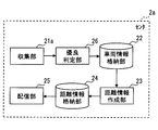
- the center 2a includes a collection unit 21a, a vehicle information storage unit 22, a distance information creation unit 23, a distance information storage unit 24, a distribution unit 25, and an excellentness determination unit 26.
- the center 2 a is the same as the center 2 of the first embodiment except that the center 2 a includes the superiority determination unit 26 and the point that the collection unit 21 a is provided instead of the collection unit 21.
- the collection unit 21a is the same as the collection unit 21 of the first embodiment except that driving operation information is acquired in addition to the instruction related information.
- the quality determination unit 26 determines whether or not the driver of the vehicle from which the driving operation information is transmitted is a good driver in the same manner as the quality determination unit 107 of the first embodiment. Determine.
- the quality determination unit 26 corresponds to a center-side quality determination unit.
- the center 2a may be provided with a map database, and the map data stored in the map database may be used to determine whether the driver is a good driver. If it is determined that the driver is a good driver, the instruction related information acquired from the transmission source of the driving operation information used for the determination is stored in the vehicle information storage unit 22.
- the center 2a generates a representative value of the actual operation distance for the excellent driver, and the driving support ECU 10a uses this representative value as the operation start distance. Therefore, similarly to the configuration of the first embodiment, the timing for notifying the surroundings of the direction of the left or right turn of the vehicle can be set to a timing at which it is more difficult to cause confusion in the surroundings.
- the driving support ECUs 10 and 10a acquire the operation start distance information downloaded by the communication device 20 from the centers 2 and 2a.
- the configuration is not necessarily limited thereto.
- operation start distance information obtained by taking statistics at the centers 2 and 2a is recorded in advance in a storage medium, and the vehicle-side unit 1 holds the storage medium so that the driving assistance ECUs 10 and 10a It is good also as a structure (henceforth Embodiment 3) which acquires operation start distance information from a storage medium.
- the driving support ECUs 10 and 10a can use the representative values of the actual operation distances statistically calculated at the center 2 for each approach link based on the actual operation distances acquired from a plurality of vehicles. As in the first configuration, it is possible to turn on the direction indicator 61 at an appropriate timing that is less likely to cause confusion in the surroundings according to each intersection approach path.
- Modification 1 In the above-described embodiment, the configuration in which the distance specifying unit 114 specifies the operation start distance for each approach link is shown, but the configuration is not necessarily limited thereto. For example, it is good also as a structure which specifies the operation start distance according to an approach link and a speed zone.
- the vehicle information acquisition units 106, 106a are detected.
- the vehicle speed of the vehicle acquired from the above may be stored in the measurement result storage unit 110 in association with the measured actual operation distance.
- the transmission processing units 111 and 111a upload the vehicle speed associated with the actual operation distance to the center 2 by including the vehicle speed associated with the actual operation distance.
- the vehicle speed of the host vehicle associated with the measured actual operation distance may be configured to use the vehicle speed at other timings as long as the vehicle speed is not close to the intersection where the actual operation distance is measured.
- the distance information creation unit 23 of the centers 2 and 2a uses the actual operation distance stored in the vehicle information storage unit 22 as the link ID and the vehicle speed associated with the actual operation distance. Based on the above, statistics will be provided for each approach link and vehicle speed range. And the representative value of the actual operation distance according to the approach link and the vehicle speed zone is created by calculating the representative value of the actual operation distance according to the approach link and the vehicle speed zone.
- the vehicle speed zone may be 1 m units, 5 m units, 10 m units, or other units.
- the communication device 20 of the vehicle side unit 1 downloads information on the representative value of the actual operation distance for each approach link and vehicle speed zone (that is, operation start distance information).
- the distance specifying unit 114 starts the operation stored in the vehicle information on the map and the distance information storage unit 113 sequentially specified by the travel position specifying unit 102.
- the operation start distance corresponding to the approach link where the host vehicle is located and the vehicle speed of the host vehicle is specified.
- the distance specifying unit 114 is based on the operation start distance information stored in the distance information storage unit 113 and is associated with the link ID of the approach link where the host vehicle is located and the vehicle speed zone to which the host vehicle speed belongs.
- a representative value of the operation distance is extracted, and the extracted representative value is specified as the operation start distance.
- the configuration of the modified example 1 it is possible to specify the operation start distance according to the tendency of the drivers of a plurality of vehicles not only for each intersection approaching road but also for each vehicle speed zone. Therefore, even when the appropriate timing of operation of the direction indicator 61 that does not easily cause confusion is different depending on the vehicle speed zone, the direction indicator 61 is lit at an appropriate timing that does not cause confusion around. Is possible.
- Modification 2 Moreover, it is good also as a structure which specifies the operation start distance according to an approach link and a right-left turn.
- the second modification when the actual operation distance is measured by the distance measuring unit 109 of the driving assistance ECU 10, 10a, a winker signal at the time of turning left and right is acquired from the body ECU 60, and the measured actual operation distance and the string are linked.
- it may be configured to be stored in the measurement result storage unit 110.
- a blinker signal at the time of a right turn is linked, and when turning left, a blinker signal at the time of a left turn is associated.
- the transmission processing units 111 and 111a include the blinker signal associated with the actual operation distance in the instruction related information and upload it to the center 2.
- the distance information creation unit 23 of the centers 2 and 2a uses the actual operation distance stored in the vehicle information storage unit 22 as the link ID and the winker associated with the actual operation distance. Based on the direction indicated by the signal, statistics are made for each approach link and left / right turn. Then, the representative value of the actual operation distance for each approach link and right / left turn is created by calculating the representative value of the actual operation distance for each approach link and right / left turn.
- the communication device 20 of the vehicle-side unit 1 downloads information on the representative value of the actual operation distance for each approach link and left / right turn (that is, operation start distance information).
- the distance specifying unit 114 starts the operation stored in the vehicle information on the map and the distance information storage unit 113 sequentially specified by the travel position specifying unit 102.
- the operation start distance corresponding to the approach link where the host vehicle is located and the direction indicated by the winker signal is specified.
- the distance specifying unit 114 is linked in the left or right direction indicated by the link ID of the approach link where the host vehicle is located and the blinker signal from the operation start distance information stored in the distance information storage unit 113.
- a representative value of the actual operation distance is extracted, and the extracted representative value is specified as the operation start distance.
- the configuration of the modified example 2 it is possible to specify the operation start distance according to the tendency of the drivers of a plurality of vehicles not only for each intersection approaching road but also for each turn of the own vehicle. Therefore, even when the appropriate timing of operation of the direction indicator 61 is less likely to cause confusion around the right turn and left turn of the vehicle, the direction is determined at an appropriate timing that is less likely to cause confusion around.
- the indicator 61 can be turned on.
- Modification 3 Moreover, it is good also as a structure which specifies the operation start distance according to an approach link and a time slot
- the third modification when the actual operation distance is measured by the distance measurement unit 109 of the driving assistance ECU 10, 10a, the current time is acquired and linked to the measured actual operation distance, and the measurement result storage unit 110 is obtained. It may be configured to be stored in.
- the transmission processing units 111 and 111a upload the current time associated with the actual operation distance to the center 2 by including the current time in the instruction related information.
- the current time may be acquired from, for example, a real-time clock built in the driving support ECUs 10 and 10a.
- the distance information creating unit 23 of the centers 2 and 2a uses the actual operation distance stored in the vehicle information storage unit 22 as the current time associated with the actual operation distance. And statistics by approach link and time zone.
- the time zone may be a unit of several hours, a unit roughly dividing day and night, or another unit.
- the representative value of the actual operation distance according to the approach link and the time zone is created by calculating the representative value of the actual operation distance according to the approach link and the time zone.
- the communication device 20 of the vehicle-side unit 1 downloads information on the representative value of the actual operation distance for each approach link and time zone (that is, operation start distance information).
- the distance specifying unit 114 starts the operation stored in the distance information storage unit 113 and the vehicle position of the vehicle on the map that is sequentially specified by the travel position specifying unit 102. Using the distance information and, for example, the current time acquired from the real-time clock, the approach link where the vehicle is located and the operation start distance according to the current time are specified. Specifically, the distance specifying unit 114 determines, based on the operation start distance information stored in the distance information storage unit 113, the actual operation distance associated with the link ID of the approach link where the host vehicle is located and the time zone to which the current time belongs. Is extracted, and the extracted representative value is specified as the operation start distance.
- the configuration of the modified example 3 it is possible to specify the operation start distance according to the tendency of the driver of a plurality of vehicles not only by the intersection approach road but also by the time zone. Therefore, even when the appropriate timing of operation of the direction indicator 61 that does not easily cause disturbance in the surroundings varies depending on the time zone, the direction indicator 61 is turned on at an appropriate timing that does not cause disturbance in the surroundings. Is possible.
- the transmission processing units 111 and 111a include the weather information associated with the actual operation distance in the instruction related information and upload it to the center 2.
- the weather information may be obtained from the server device outside the host vehicle via the communication device 20, for example.
- the detection result of the rain sensor of the own vehicle may be acquired as weather information, or the detection result of the sensor that detects the road surface state provided on the tire of the own vehicle may be acquired as weather information.
- the distance information creation unit 23 of the centers 2 and 2a uses the actual operation distance stored in the vehicle information storage unit 22 as the weather information associated with the actual operation distance. Based on the approach links and weather. About the weather, it is good also as a structure which divides clear and cloudy, rain, snow, etc. It is good also as a structure which divides whether it is rain, It is good also as a structure which divides whether it is road surface freezing. It is good also as a structure made into a division. Then, the representative value of the actual operation distance for each approach link and weather is created by calculating the representative value of the actual operation distance for each approach link and weather. The communication device 20 of the vehicle-side unit 1 downloads information on the representative value of the actual operation distance for each approach link and weather (that is, operation start distance information).
- the distance specifying unit 114 starts the operation stored in the vehicle position of the host vehicle on the map sequentially specified by the travel position specifying unit 102 and the distance information storage unit 113. Using the distance information and the current weather, an approach link where the vehicle is located and an operation start distance according to the weather are specified. Specifically, the distance specifying unit 114 extracts the link ID of the approach link where the host vehicle is located and the representative value of the actual operation distance associated with the weather from the operation start distance information stored in the distance information storage unit 113. The extracted representative value is specified as the operation start distance.
- the configuration of the modified example 4 it is possible to specify the operation start distance along the tendency of the driver of a plurality of vehicles, not only by the intersection approach road but also by the weather. Therefore, even when the appropriate timing of operation of the direction indicator 61 that does not easily cause disturbance in the surroundings varies depending on the weather, the direction indicator 61 can be turned on at an appropriate timing that does not easily cause disturbance in the surroundings. It becomes possible. Note that a configuration in which some or all of the first to fourth modifications are combined may be employed.
- the travel plan generation unit 104 of the driving assistance ECUs 10 and 10a has shown the configuration for generating the recommended route for directing the vehicle to the destination as the medium- to long-term travel plan.
- the driving support ECUs 10 and 10a may be configured to generate a recommended route for causing the center 2 or 2a to direct the vehicle toward the destination and acquire the recommended route generated at the center 2 or 2a.
- Modification 6 In the above-described embodiment, the case where the present invention is applied to a vehicle capable of switching between automatic driving and manual driving has been described, but the present invention is not necessarily limited thereto. For example, as a sixth modification, it may be configured to be applied to a vehicle that does not perform automatic driving.
- Modification 7 Further, as a seventh modified example, a configuration that is applied to a vehicle that does not perform manual driving may be employed.
Landscapes
- Engineering & Computer Science (AREA)
- Mechanical Engineering (AREA)
- Lighting Device Outwards From Vehicle And Optical Signal (AREA)
- Traffic Control Systems (AREA)
Applications Claiming Priority (2)
| Application Number | Priority Date | Filing Date | Title |
|---|---|---|---|
| JP2016089755A JP6524956B2 (ja) | 2016-04-27 | 2016-04-27 | 運転支援装置及びセンタ |
| JP2016-089755 | 2016-04-27 |
Publications (1)
| Publication Number | Publication Date |
|---|---|
| WO2017187931A1 true WO2017187931A1 (ja) | 2017-11-02 |
Family
ID=60160497
Family Applications (1)
| Application Number | Title | Priority Date | Filing Date |
|---|---|---|---|
| PCT/JP2017/014469 Ceased WO2017187931A1 (ja) | 2016-04-27 | 2017-04-07 | 運転支援装置及びセンタ |
Country Status (2)
| Country | Link |
|---|---|
| JP (1) | JP6524956B2 (enExample) |
| WO (1) | WO2017187931A1 (enExample) |
Cited By (4)
| Publication number | Priority date | Publication date | Assignee | Title |
|---|---|---|---|---|
| CN110281919A (zh) * | 2018-03-14 | 2019-09-27 | 本田技研工业株式会社 | 车辆控制装置、车辆控制方法以及存储介质 |
| CN112399931A (zh) * | 2018-07-12 | 2021-02-23 | 日产自动车株式会社 | 行驶辅助方法和行驶辅助装置 |
| CN113508056A (zh) * | 2019-03-08 | 2021-10-15 | 伟摩有限责任公司 | 针对自主车辆的转弯发出信号 |
| WO2024086050A1 (en) * | 2022-10-20 | 2024-04-25 | Motional Ad Llc | Turn signal assignment for complex maneuvers |
Families Citing this family (2)
| Publication number | Priority date | Publication date | Assignee | Title |
|---|---|---|---|---|
| CN110758232B (zh) * | 2019-10-15 | 2021-04-13 | 中国第一汽车股份有限公司 | 一种车辆转向灯控制方法、车辆及存储介质 |
| WO2022241659A1 (zh) * | 2021-05-18 | 2022-11-24 | 浙江智马达智能科技有限公司 | 转向灯控制系统、控制方法及具有其的车辆 |
Citations (6)
| Publication number | Priority date | Publication date | Assignee | Title |
|---|---|---|---|---|
| JP2004045291A (ja) * | 2002-07-12 | 2004-02-12 | Denso Corp | 車両制御システム |
| JP2008087711A (ja) * | 2006-10-04 | 2008-04-17 | Aisin Aw Co Ltd | 運転支援装置 |
| JP2008279990A (ja) * | 2007-05-14 | 2008-11-20 | Mitsubishi Electric Corp | 方向指示器動作システム |
| JP2011221573A (ja) * | 2010-04-02 | 2011-11-04 | Denso Corp | 運転支援装置および運転支援システム |
| WO2015141308A1 (ja) * | 2014-03-18 | 2015-09-24 | 日産自動車株式会社 | 車両操作装置 |
| US20150266413A1 (en) * | 2011-11-22 | 2015-09-24 | Sara Elyse Raubvogel | Automatic Activation of Turn Signals In A Vehicle |
-
2016
- 2016-04-27 JP JP2016089755A patent/JP6524956B2/ja active Active
-
2017
- 2017-04-07 WO PCT/JP2017/014469 patent/WO2017187931A1/ja not_active Ceased
Patent Citations (6)
| Publication number | Priority date | Publication date | Assignee | Title |
|---|---|---|---|---|
| JP2004045291A (ja) * | 2002-07-12 | 2004-02-12 | Denso Corp | 車両制御システム |
| JP2008087711A (ja) * | 2006-10-04 | 2008-04-17 | Aisin Aw Co Ltd | 運転支援装置 |
| JP2008279990A (ja) * | 2007-05-14 | 2008-11-20 | Mitsubishi Electric Corp | 方向指示器動作システム |
| JP2011221573A (ja) * | 2010-04-02 | 2011-11-04 | Denso Corp | 運転支援装置および運転支援システム |
| US20150266413A1 (en) * | 2011-11-22 | 2015-09-24 | Sara Elyse Raubvogel | Automatic Activation of Turn Signals In A Vehicle |
| WO2015141308A1 (ja) * | 2014-03-18 | 2015-09-24 | 日産自動車株式会社 | 車両操作装置 |
Cited By (6)
| Publication number | Priority date | Publication date | Assignee | Title |
|---|---|---|---|---|
| CN110281919A (zh) * | 2018-03-14 | 2019-09-27 | 本田技研工业株式会社 | 车辆控制装置、车辆控制方法以及存储介质 |
| CN110281919B (zh) * | 2018-03-14 | 2022-08-26 | 本田技研工业株式会社 | 车辆控制装置、车辆控制方法以及存储介质 |
| CN112399931A (zh) * | 2018-07-12 | 2021-02-23 | 日产自动车株式会社 | 行驶辅助方法和行驶辅助装置 |
| CN113508056A (zh) * | 2019-03-08 | 2021-10-15 | 伟摩有限责任公司 | 针对自主车辆的转弯发出信号 |
| WO2024086050A1 (en) * | 2022-10-20 | 2024-04-25 | Motional Ad Llc | Turn signal assignment for complex maneuvers |
| US12377776B2 (en) | 2022-10-20 | 2025-08-05 | Motional Ad Llc | Turn signal assignment for complex maneuvers |
Also Published As
| Publication number | Publication date |
|---|---|
| JP2017197027A (ja) | 2017-11-02 |
| JP6524956B2 (ja) | 2019-06-05 |
Similar Documents
| Publication | Publication Date | Title |
|---|---|---|
| JP7750324B2 (ja) | 自動運転装置、車両制御方法 | |
| JP7315101B2 (ja) | 障害物情報管理装置、障害物情報管理方法、車両用装置 | |
| US12387594B2 (en) | Parking-stopping point management device, parking-stopping point management method, and vehicle device | |
| JP6711016B2 (ja) | 走行支援装置 | |
| JP6520862B2 (ja) | 自動運転システム | |
| JP6790463B2 (ja) | 走行支援装置 | |
| JP6524956B2 (ja) | 運転支援装置及びセンタ | |
| US11702087B2 (en) | Autonomous driving monitoring system | |
| CN109795500B (zh) | 车辆控制装置、车辆控制方法及存储介质 | |
| JP7348942B2 (ja) | 車両制御装置、車両制御方法、およびプログラム | |
| JP7289855B2 (ja) | 車両制御システムおよび車両制御方法 | |
| US20210070289A1 (en) | Vehicle control device, vehicle control method, and storage medium | |
| CN113815640B (zh) | 用于具有不同速度限制的车道的车道变更系统 | |
| JP2025061564A (ja) | 潜在事故責任決定装置 | |
| JP2017224107A (ja) | センタ及び運転支援システム | |
| RU2771332C1 (ru) | Способ управления транспортным средством и устройство управления транспортным средством | |
| CN118805151A (zh) | 一种智能驾驶方法、装置及包括该装置的车辆 | |
| US12377775B2 (en) | Vehicle control method and vehicle control device | |
| CN115230732B (zh) | 远程功能选择装置 | |
| CN120345015A (zh) | 用于经由运动推断的交通灯标记的方法和系统 | |
| US20210370941A1 (en) | Precautionary slowdown speed planning | |
| US11735044B2 (en) | Information transmission system | |
| US11906323B2 (en) | Map generation apparatus | |
| JP2017182494A (ja) | 運転支援装置 | |
| CN118062050A (zh) | 用于控制车辆操作的高性能计算(hpc)系统的相互监测 |
Legal Events
| Date | Code | Title | Description |
|---|---|---|---|
| NENP | Non-entry into the national phase |
Ref country code: DE |
|
| 121 | Ep: the epo has been informed by wipo that ep was designated in this application |
Ref document number: 17789219 Country of ref document: EP Kind code of ref document: A1 |
|
| 122 | Ep: pct application non-entry in european phase |
Ref document number: 17789219 Country of ref document: EP Kind code of ref document: A1 |