WO2017187931A1 - Driving assistance device and center - Google Patents
Driving assistance device and center Download PDFInfo
- Publication number
- WO2017187931A1 WO2017187931A1 PCT/JP2017/014469 JP2017014469W WO2017187931A1 WO 2017187931 A1 WO2017187931 A1 WO 2017187931A1 JP 2017014469 W JP2017014469 W JP 2017014469W WO 2017187931 A1 WO2017187931 A1 WO 2017187931A1
- Authority
- WO
- WIPO (PCT)
- Prior art keywords
- vehicle
- distance
- unit
- intersection
- information
- Prior art date
Links
- 238000013459 approach Methods 0.000 claims abstract description 84
- 238000012545 processing Methods 0.000 claims description 29
- 230000005540 biological transmission Effects 0.000 claims description 22
- 238000005259 measurement Methods 0.000 description 43
- 238000004891 communication Methods 0.000 description 39
- 238000000034 method Methods 0.000 description 32
- 230000008569 process Effects 0.000 description 30
- 230000006870 function Effects 0.000 description 29
- 238000012986 modification Methods 0.000 description 23
- 230000004048 modification Effects 0.000 description 23
- 230000008859 change Effects 0.000 description 14
- 238000012544 monitoring process Methods 0.000 description 12
- 230000001133 acceleration Effects 0.000 description 8
- 238000001514 detection method Methods 0.000 description 8
- 238000010586 diagram Methods 0.000 description 6
- 230000002093 peripheral effect Effects 0.000 description 4
- 230000006399 behavior Effects 0.000 description 3
- 239000000725 suspension Substances 0.000 description 3
- 239000000284 extract Substances 0.000 description 2
- 230000007774 longterm Effects 0.000 description 2
- 241000282412 Homo Species 0.000 description 1
- 241001465754 Metazoa Species 0.000 description 1
- 230000003044 adaptive effect Effects 0.000 description 1
- 238000005516 engineering process Methods 0.000 description 1
- 230000008014 freezing Effects 0.000 description 1
- 238000007710 freezing Methods 0.000 description 1
- 238000003384 imaging method Methods 0.000 description 1
- 238000009434 installation Methods 0.000 description 1
- 230000007257 malfunction Effects 0.000 description 1
- 230000000737 periodic effect Effects 0.000 description 1
Images
Classifications
-
- B—PERFORMING OPERATIONS; TRANSPORTING
- B60—VEHICLES IN GENERAL
- B60Q—ARRANGEMENT OF SIGNALLING OR LIGHTING DEVICES, THE MOUNTING OR SUPPORTING THEREOF OR CIRCUITS THEREFOR, FOR VEHICLES IN GENERAL
- B60Q1/00—Arrangement of optical signalling or lighting devices, the mounting or supporting thereof or circuits therefor
- B60Q1/26—Arrangement of optical signalling or lighting devices, the mounting or supporting thereof or circuits therefor the devices being primarily intended to indicate the vehicle, or parts thereof, or to give signals, to other traffic
- B60Q1/34—Arrangement of optical signalling or lighting devices, the mounting or supporting thereof or circuits therefor the devices being primarily intended to indicate the vehicle, or parts thereof, or to give signals, to other traffic for indicating change of drive direction
- B60Q1/346—Arrangement of optical signalling or lighting devices, the mounting or supporting thereof or circuits therefor the devices being primarily intended to indicate the vehicle, or parts thereof, or to give signals, to other traffic for indicating change of drive direction with automatic actuation
-
- B—PERFORMING OPERATIONS; TRANSPORTING
- B60—VEHICLES IN GENERAL
- B60Q—ARRANGEMENT OF SIGNALLING OR LIGHTING DEVICES, THE MOUNTING OR SUPPORTING THEREOF OR CIRCUITS THEREFOR, FOR VEHICLES IN GENERAL
- B60Q1/00—Arrangement of optical signalling or lighting devices, the mounting or supporting thereof or circuits therefor
- B60Q1/26—Arrangement of optical signalling or lighting devices, the mounting or supporting thereof or circuits therefor the devices being primarily intended to indicate the vehicle, or parts thereof, or to give signals, to other traffic
- B60Q1/34—Arrangement of optical signalling or lighting devices, the mounting or supporting thereof or circuits therefor the devices being primarily intended to indicate the vehicle, or parts thereof, or to give signals, to other traffic for indicating change of drive direction
Definitions
- the present disclosure relates to a driving support device and a center that support driving of a vehicle.
- Patent Document 1 discloses a technique for controlling the timing for informing the surroundings of the direction of the vehicle's right / left turn.
- 30 m before the guidance intersection is set as a recommended point where the direction indicator should be turned on. And even if the direction indicator switch is operated before this recommended point, the direction indicator is not lit until the recommended point is reached, and the direction indicator is lit when the recommended point is reached. . If there is an approach path in the direction corresponding to the lighting instruction signal input via the direction indicator switch between the recommended point and the guidance intersection, the direction indicator will proceed after the process proceeds until there is no such approach path. Lights up.
- the recommended point is uniformly determined by the distance from the intersection.
- the appropriate timing at which the direction indicator should be turned on is different depending on the individual intersection approach path, which is less likely to cause confusion in the surroundings.
- the present disclosure has been made in view of the above-described conventional problems, and the purpose of the present disclosure is to make the timing for informing the direction of the vehicle's right / left turn to the surroundings less likely to cause confusion in the surroundings.
- a driving support apparatus is used in a vehicle and starts a position acquisition unit that acquires the position of the host vehicle, a map data acquisition unit that acquires map data, and an operation of a direction indicator in front of an intersection.
- the distance acquisition unit that acquires the operation start distance information indicating the operation start distance for each approach road, the position of the vehicle acquired by the position acquisition unit, the map data acquired by the map data acquisition unit, and the distance acquisition unit Using the acquired operation start distance information, the distance specifying unit that specifies the operation start distance on the intersection approach road where the vehicle is located, and the operation specified by the distance specifying unit when the vehicle makes a right or left turn at the intersection
- a direction indication support unit that provides support so that the operation of the direction indicator of the host vehicle is started at the start distance.
- the operation start distance at which the operation of the direction indicator should be started before the intersection on the approach path is specified. Therefore, the distance at which the operation of the direction indicator should be started before the intersection can be specified for each intersection approach path.
- the direction indication support unit provides support so that the operation of the direction indicator of the own vehicle is started at the specified operation start distance, so that it is difficult for the surroundings to be confused according to each intersection approach path. It is possible to turn on the direction indicator at an appropriate timing. As a result, the timing for notifying the surroundings of the direction of the vehicle's right or left turn can be set to a timing that is less likely to cause confusion in the surroundings.
- the center transmits a plurality of vehicles, and when the vehicle makes a right or left turn at the intersection, the driver of the vehicle operates the direction indicator in front of the intersection.
- the direction indicator in front of the intersection is obtained by collecting the indicator-related information including the distance from which the vehicle started and the indicator-related information obtained from multiple vehicles in the collector by statistics for each approach road
- the creation unit that creates the operation start distance information that shows the operation start distance for each intersection approach path that should start the operation of the vessel, and the operation start distance information created by the creation unit
- a distribution unit that transmits the information to the vehicle that supports the operation so that the operation of the direction indicator is started at the operation start distance on the intersection approach road where the vehicle is located using the operation start distance information.
- the operation start distance at which the operation of the direction indicator should be started before the intersection is entered. Since the operation start distance information shown for each road is created, it is possible to create the operation start distance information along the tendency of drivers of a plurality of vehicles. And since this operation start distance information is transmitted from a delivery part to a vehicle, in this vehicle, operation of a direction indicator starts with the operation start distance along the tendency of drivers of a plurality of vehicles on an intersection approach road where the vehicle is located. It will be possible to provide support in the same way.
- the timing for notifying the surroundings of the direction of the vehicle's right or left turn can be set to a timing that is less likely to cause confusion in the surroundings.
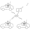
- FIG. 1 is a diagram illustrating an example of a schematic configuration of a driving support system
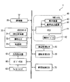
- FIG. 2 is a diagram illustrating an example of a schematic configuration of the vehicle-side unit.
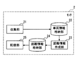
- FIG. 3 is a diagram showing an example of a schematic configuration of the center.
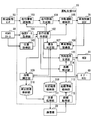
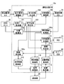
- FIG. 4 is a diagram illustrating an example of a schematic configuration of the driving assistance ECU.
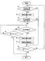
- FIG. 5 is a flowchart illustrating an example of a flow of distance measurement related processing in the distance measurement unit
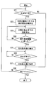
- FIG. 6 is a flowchart illustrating an example of a flow of support-related processing in the driving support ECU.
- FIG. 7 is a diagram illustrating an example of a schematic configuration of the driving assistance ECU.
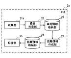
- FIG. 8 is a diagram illustrating an example of a schematic configuration of the center.
- the driving support system 3 includes a vehicle-side unit 1 and a center 2 that are used for each of a plurality of vehicles.
- the vehicle-side unit 1 is used for a vehicle that performs automatic driving for automatically controlling acceleration, braking, and steering, and communicates with the center 2.
- the center 2 is a server device, for example, and collects information transmitted from each vehicle-side unit 1 mounted on a plurality of vehicles, or creates information created based on the collected information for each vehicle-side unit 1. Or send to.
- the center 2 may be composed of a single server device or may be composed of a plurality of server devices.
- the vehicle-side unit 1 is used for an autonomous driving vehicle.
- the vehicle-side unit 1 includes a driving assistance ECU 10, a communication device 20, an ADAS (Advanced Driver Assistance Systems) locator 30, an HMI (Human Machine Interface) system 40, A periphery monitoring sensor 50, a body ECU 60, a direction indicator 61, a winker switch 62, and a vehicle control ECU 70 are included.
- the driving support ECU 10, the communication device 20, the ADAS locator 30, the HMI system 40, the body ECU 60, and the vehicle control ECU 70 are connected to, for example, an in-vehicle LAN, and can exchange information with each other by communication.
- the communication device 20 communicates with the center 2.
- the communication device 20 may be configured to communicate with the center 2 using a communication module for performing communication via a public communication network such as a mobile phone network or the Internet.
- a communication module for telematics communication such as DCM (Data Communication Module) may be configured to communicate with the center 2 via a communication network used for telematics communication.
- the communication device 20 outputs information downloaded from the center 2 to the in-vehicle LAN, and uploads information transmitted from the driving support ECU 10 to the center 2 through the in-vehicle LAN.
- the communication device 20 may be configured to communicate with the center 2 via a roadside device.
- the ADAS locator 30 includes a GNSS (Global Navigation Satellite System) receiver 31, an inertial sensor 32, and a map database (hereinafter referred to as DB) 33 storing map data.
- the GNSS receiver 31 receives positioning signals from a plurality of artificial satellites.
- the inertial sensor 32 includes, for example, a triaxial gyro sensor and a triaxial acceleration sensor.
- the map DB 33 is a nonvolatile memory, and stores map data such as link data, node data, road shapes, and structures.
- Link data includes a unique number (link ID) that identifies the link, link length indicating the link length, link direction, link shape information, node coordinates (latitude / longitude) of the start and end of the link, and connection to the node Connection link IDs in which link IDs of all links to be described are described, link attributes describing whether each link connected to a node is an incoming link or an outgoing link, and road attribute data Consists of The road attributes include road name, road type, road width, number of lanes, speed regulation value, and the like.
- the node data includes a node ID, a node coordinate, a node name, a node type, a link ID of a link connected to the node, an intersection type, etc. Composed of each data.
- the ADAS locator 30 sequentially measures the vehicle position of the vehicle on which the ADAS locator 30 is mounted by combining the positioning signal received by the GNSS receiver 31 and the measurement result of the inertial sensor 32. In addition, it is good also as a structure which uses the travel distance calculated
- the ADAS locator 30 also reads map data from the map DB 33 and outputs it to the in-vehicle LAN. The map data may be obtained from the outside of the vehicle using a communication module.
- the HMI system 40 includes an HCU (Human Machine Interface Control Unit) 41, an operation device 42, a display device 43, and an audio output device 44, as shown in FIG.
- the HMI system receives an input operation from the driver of the own vehicle or presents information to the driver of the own vehicle.
- the operation device 42 is a group of switches operated by the driver of the own vehicle.
- the operation device 42 is used for performing various settings.
- the operation device 42 there are a steering switch provided in a spoke spoke portion of the own vehicle, a touch switch integrated with the display device 43, and the like.
- the display device 43 presents information by displaying text and / or images. Examples of the display device 43 include a combination meter, CID (Center Information Display), and HUD (Head-Up Display).
- the audio output device presents information by outputting audio. Examples of the audio output device 44 include an audio speaker.
- the HCU 41 includes a CPU, a volatile memory, a nonvolatile memory, an I / O, and a bus for connecting them, and executes various processes by executing a control program stored in the nonvolatile memory.
- the HCU 41 causes the display device 43 and / or the audio output device 44 to present information in accordance with an instruction from the driving support ECU 10. Information presentation at the HCU 41 will be described in detail later.
- the periphery monitoring sensor 50 detects obstacles such as moving objects such as pedestrians, animals other than humans, bicycles, motorcycles, and other vehicles, and falling objects on the road, guardrails, curbs, and stationary objects such as trees. In addition, road markings such as travel lane markings and stop lines are detected.
- the peripheral monitoring sensor 50 is, for example, a peripheral monitoring camera that captures a predetermined range around the host vehicle, a millimeter wave radar that transmits an exploration wave to the predetermined range around the host vehicle, sonar, LIDAR (Light Detection and Ranging / Laser Imaging Detect ion and Ranging). The peripheral monitoring camera sequentially outputs captured images that are sequentially captured to the peripheral monitoring ECU 51 as sensing information.
- a sensor that transmits an exploration wave such as sonar, millimeter wave radar, or LIDAR sequentially outputs a scanning result based on a reception signal obtained when a reflected wave reflected by an obstacle is received to the driving support ECU 10 as sensing information.
- the direction indicator 61 is a so-called blinker, and transmits a direction in which the host vehicle changes its direction to the surroundings by turning on one of the left and right lamps.
- the winker switch 62 is a switch for detecting an operation of a winker lever that is an operation member for performing a lamp lighting operation of the direction indicator 61, and turns right or left in accordance with an operation of the winker lever (hereinafter, winker operation). Outputs the hour signal.
- the body ECU 60 is an electronic control device that controls electrical components such as the direction indicator 61. For example, the body ECU 60 executes control to turn on the lamp of the direction indicator 61 in accordance with the winker signal input from the winker switch 62. The body ECU 60 can output this blinker signal to the in-vehicle LAN.
- the vehicle control ECU 70 is an electronic control device that performs acceleration / deceleration control and / or steering control of the host vehicle.
- the vehicle control ECU 70 includes a steering ECU that performs steering control, a power unit control ECU that performs acceleration / deceleration control, a brake ECU, and the like.
- the vehicle control ECU 70 acquires detection signals output from sensors such as an accelerator position sensor, a brake pedal force sensor, a rudder angle sensor, and a wheel speed sensor mounted on the host vehicle, and performs electronic control throttle, brake actuator, EPS (Electric Power Steering) Outputs control signals to each travel control device such as a motor. Further, the vehicle control ECU 70 can output the detection signals of the above-described sensors to the in-vehicle LAN.
- the driving support ECU 10 includes a CPU, a volatile memory, a non-volatile memory, an I / O, and a bus for connecting them, and executes various processes by executing a control program stored in the non-volatile memory.
- the driving assistance ECU 10 recognizes the traveling environment of the vehicle from the sensing result of the surrounding monitoring sensor 50.
- the driving assistance ECU 10 controls the vehicle control ECU 70 to perform a driving operation by the driver.
- the driving assistance ECU 10 causes the communication device 20 to upload information related to the winker operation by the driver (hereinafter referred to as instruction-related information) from the communication device 20 to the center 2 when the host vehicle makes a right or left turn.
- the instruction-related information includes the intersection approach path (that is, the approach link) when the vehicle makes a right or left turn at the intersection, and the distance at which the driver of the vehicle starts the lamp operation of the direction indicator before the intersection ( Hereinafter, the actual operation distance) and a time stamp indicating the time when the actual operation distance was measured are included.
- the approach link information for example, a configuration using the link ID of the approach link may be used.
- the driving assistance ECU 10 executes processing related to operation assistance of the direction indicator 61.
- This driving support ECU 10 corresponds to a driving support device. The processing in the driving support ECU 10 will be described in detail later. Note that some or all of the functions executed by the driving support ECU 10 may be configured in hardware by one or a plurality of ICs.
- the center 2 is a server device, for example, and includes a collection unit 21, a vehicle information storage unit 22, a distance information creation unit 23, a distance information storage unit 24, and a distribution unit 25, as shown in FIG. Yes.
- the collection unit 21 acquires information uploaded from the vehicle-side unit 1.
- the collection unit 21 stores the above-described instruction-related information uploaded from the vehicle-side unit 1 mounted on each of the plurality of vehicles in the vehicle information storage unit 22, whereby the instruction-related information about the plurality of vehicles is stored. Collect information.
- the vehicle information storage unit 22 may be configured to use an electrically readable and writable nonvolatile memory.
- the instruction-related information may be stored in the vehicle information storage unit 22 in association with the actual operation distance and the time stamp indicating the time when the actual operation distance is measured for each approach link. If the memory capacity of the vehicle information storage unit 22 is exceeded, the old information may be sequentially deleted based on the time stamp.
- the distance information creation unit 23 stats the actual operation distance stored in the vehicle information storage unit 22 for each approach link, and calculates a representative value of the actual operation distance for each approach link, thereby calculating the actual operation distance for each approach link. Create a representative value for. Examples of the representative value include an average value, a median value, and a mode value. Note that the unit of the actual operation distance in calculating the representative value is not limited to, for example, 1 m units, and may be 5 m units, 10 m units, or the like.
- the distance information creating unit 23 stores the created representative value of the actual operation distance for each approach link in the distance information storage unit 24 for each approach link.
- the link ID of the approach link and the representative value of the actual operation distance may be stored in association with each other.
- the information on the representative value of the actual operation distance for each approach link is hereinafter referred to as operation start distance information.
- the distance information storage unit 24 may be configured to use an electrically readable and writable nonvolatile memory. This distance information creation unit 23 corresponds to a creation unit.
- the distribution unit 25 transmits the operation start distance information stored in the distance information storage unit 24 to the vehicle-side unit 1.
- the operation start distance information may be transmitted to the vehicle side unit 1 that has requested transmission of the operation start distance information.
- the vehicle position is transmitted from the vehicle-side unit 1 in order to reduce the communication amount, and the distribution unit 25 starts an operation within a predetermined range around the vehicle on which the vehicle-side unit 1 is mounted based on the vehicle position. What is necessary is just to set it as the structure which transmits distance information.
- the predetermined range for example, within a radius of several kilometers, within a mesh to which the vehicle position belongs, and the like can be mentioned.
- the distribution unit 25 transmits the operation start distance information to the roadside machine connected to the center 2 through the communication network, and the operation start distance information from the roadside machine to the vehicle side unit 1 located within the communication range of the roadside machine. May be configured to transmit. In this case, the distribution unit 25 may transmit the operation start distance information within a predetermined range (for example, within a radius of several kilometers) around the installation position of the roadside machine.
- the driving assistance ECU 10 includes a position acquisition unit 100, a map data acquisition unit 101, a travel position identification unit 102, a travel environment recognition unit 103, a travel plan generation unit 104, an automatic driving function unit 105, and vehicle information acquisition.
- Unit 106, superiority determination unit 107, determination result storage unit 108, distance measurement unit 109, measurement result storage unit 110, transmission processing unit 111, distance acquisition unit 112, distance information storage unit 113, distance identification unit 114, and direction indication support Part 115 is provided.
- the position acquisition unit 100 acquires the vehicle position of the host vehicle output from the ADAS locator 30.
- the map data acquisition unit 101 acquires map data output from the ADAS locator 30.
- the travel position specifying unit 102 specifies the vehicle position of the host vehicle on the map from the vehicle position of the own vehicle acquired by the position acquisition unit 100 and the map data acquired by the map data acquisition unit 101.
- the travel environment recognition unit 103 recognizes the travel environment of the host vehicle from the vehicle position and map data of the host vehicle used in the travel position specifying unit 102, sensing information acquired from the surrounding monitoring sensor 50, and the like. As an example, the traveling environment recognition unit 103 recognizes the shape and movement state of an object around the host vehicle from the sensing information acquired from the surrounding monitoring sensor 50 within the sensing range of the surrounding monitoring sensor 50, and actually travels. Generate a virtual space that reproduces the environment. In addition, the traveling environment recognition unit 103 recognizes the traveling environment using map data outside the sensing range of the periphery monitoring sensor 50.
- the travel plan generation unit 104 generates a travel plan for driving the vehicle by automatic driving.
- the travel plan generated by the travel plan generation unit 104 is output to the automatic driving function unit 105.
- the travel plan generation unit 104 uses the vehicle position and map data of the host vehicle used by the travel position specifying unit 102 to generate a recommended route for directing the host vehicle to the destination as a medium to long-term travel plan.
- the recommended route may be configured to search using the Dijkstra method by setting a link cost so that, for example, a road suitable for running by automatic driving is prioritized.
- the travel plan generation unit 104 generates a short-term travel plan for traveling according to the recommended route, using the virtual space around the vehicle generated by the travel environment recognition unit 103. As a specific example, execution of steering for lane change, acceleration / deceleration for speed adjustment, steering and braking for obstacle avoidance, and the like is determined.
- the automatic driving function unit 105 substitutes the driving operation by the driver by causing the vehicle control ECU 70 to automatically perform acceleration, braking, and / or steering of the vehicle according to the driving plan output from the driving plan generation unit 104. Do.
- This function of performing the driving operation is called an automatic driving function.
- the automatic driving function there is an ACC (Adaptive Cruise Control) function that controls the traveling speed of the own vehicle so as to maintain the target inter-vehicle distance from the preceding vehicle by adjusting the driving force and the braking force.
- ACC Adaptive Cruise Control
- LKA Lane Keeping Assist
- LCA Longe Change Assist
- AEB Automatic Emergency Braking
- an automatic driving function a function for performing acceleration / deceleration and steering so that the vehicle position of the vehicle travels along the recommended route generated by the travel plan generation unit 104, and travel along a recommended travel locus
- a function of performing acceleration / deceleration and steering and a function of automatically stopping on a road shoulder or the like in an emergency.
- operation function it is assumed that the own vehicle automatically makes a right / left turn at an intersection by an automatic driving function.
- the automatic driving function unit 105 can switch execution / non-execution of automatic driving.
- the failure to perform automatic driving means that the driver operates all the main control systems such as the brake, steering, throttle, and driving force of the vehicle without performing automation. That is, manual operation.
- the automatic driving function unit 105 may be switched so as not to perform the automatic driving according to an input operation by the driver to the operation device 42, for example.
- the vehicle information acquisition unit 106 acquires a state quantity related to the behavior of the host vehicle from the detection result of each sensor output via the vehicle control ECU 70.
- vehicle information such as the vehicle speed, travel distance, yaw rate, and steering angle of the host vehicle is acquired.
- This vehicle information corresponds to driving operation information, and this vehicle information acquisition unit 106 corresponds to a driving operation acquisition unit.
- the vehicle information acquisition unit 106 may be configured to acquire detection signals from the sensors without using the vehicle control ECU 70.
- the superiority determination unit 107 includes the vehicle information acquired by the vehicle information acquisition unit 106, the vehicle position and map data of the host vehicle used by the travel position specifying unit 102, and the vehicle position of the host vehicle on the map specified by the travel position specifying unit 102. Etc. to determine whether or not the driver of the vehicle is a good driver that complies with traffic regulations.
- This quality determination unit 107 corresponds to a vehicle side quality determination unit. Specifically, it is determined whether or not the driver is a good driver by using as an index the ability to comply with the stop at the place where the vehicle is temporarily stopped, the compliance with the speed limit, the appropriateness of the inter-vehicle distance, the frequency of lane changes, and the like. An example is described below.
- the quality determination unit 107 stores the determination result in the determination result storage unit 108 in association with a time stamp indicating the determined time (hereinafter simply referred to as determination time).
- the determination result storage unit 108 may be configured to use an electrically readable and writable nonvolatile memory.
- the superiority determination unit 107 determines that the driver is an excellent driver when the determination results for the most recent predetermined number of times stored in the determination result storage unit 108 are determination results indicating that the vehicle has stopped before the stop line. On the other hand, if this condition is not satisfied, it is determined that the driver is not a good driver.
- the predetermined number here is a value that can be arbitrarily set, and may be one time. However, in order to further improve the determination accuracy, it is preferably a plurality of times. In addition, it is good also as a structure determined as a good driver
- the vehicle position of the vehicle on the map that is sequentially specified by the travel position specifying unit 102, the speed regulation value in the map data, and the vehicle information acquisition unit 106 are sequentially acquired. Based on the vehicle speed of the vehicle information to be determined, it is determined whether the speed limit value of the link where the vehicle is located exceeds a predetermined value or more.
- the predetermined value here is a value that can be arbitrarily set.
- the superiority determination unit 107 associates the determination result with the determination time, stores the determination result in the determination result storage unit 108, and determines whether or not the driver is a good driver in the same manner as in the case where the suspension compliance is used as an index. Note that it may be configured to determine whether or not the driver is a good driver based on a determination result of whether or not the vehicle speed of the surrounding vehicle recognized by the traveling environment recognition unit 103 exceeds a predetermined value or more.
- the inter-vehicle distance between the preceding vehicle and the host vehicle that are sequentially recognized by the traveling environment recognition unit 103 and the vehicle information among the vehicle information sequentially acquired by the vehicle information acquisition unit 106 Based on the vehicle speed, it is determined whether or not the target inter-vehicle distance corresponding to the vehicle speed of the host vehicle is less than a predetermined value.
- the target inter-vehicle distance corresponding to the vehicle speed may be the same as that set by the ACC function or the like.
- the superiority determination unit 107 associates the determination result with the determination time, stores the determination result in the determination result storage unit 108, and determines whether or not the driver is a good driver in the same manner as in the case where the suspension compliance is used as an index.
- the frequency of lane change within a predetermined distance is set as a threshold based on the travel distance and steering angle of the vehicle in the vehicle information sequentially acquired by the vehicle information acquisition unit 106. It is determined whether or not it exceeds. As an example, it may be determined whether or not the frequency of lane change within a few hundred meters is four times or more. The presence or absence of a lane change may be determined based on the change in the steering angle. In addition to the change in the steering angle, the determination may be based on the change in the yaw rate. If the vehicle position on the map can be specified for each lane, the change in the vehicle position is used. You may judge.
- the superiority determination unit 107 associates the determination result with the determination time, stores the determination result in the determination result storage unit 108, and determines whether or not the driver is a good driver in the same manner as in the case where the suspension compliance is used as an index.
- the goodness determination unit 107 may be configured to determine whether or not the driver is a good driver based on one of the above-described indexes, or may determine whether or not the driver is a good driver based on a plurality of indexes. It is good also as a structure.
- the configuration may be such that the driver is determined to be a good driver when the conditions are satisfied for all of the plurality of indicators.
- a configuration may be adopted in which a good driver is determined when the above conditions are satisfied.
- the distance measurement unit 109 starts the operation of the direction indicator in front of the intersection when the vehicle makes a right or left turn at the intersection only when the excellent determination unit 107 determines that the driver is an excellent driver.
- the measured distance (that is, the actual operation distance) is measured.
- the distance measurement unit 109 includes the vehicle position of the vehicle on the map that is sequentially identified by the travel position identifying unit 102, the travel distance of the vehicle in the vehicle information that is sequentially acquired by the vehicle information acquisition unit 106, and the body ECU 60.
- the actual operation distance is measured based on the winker signal that is sequentially acquired via the. Details of the measurement of the actual operation distance will be described later.
- the distance measuring unit 109 associates the measured actual operation distance of the own vehicle with a time stamp indicating the measurement time (hereinafter simply referred to as measurement time) and the link ID of the approach link at the time of turning left and right, and the measurement result storage unit 110.
- the measurement result storage unit 110 may be configured to use an electrically readable / writable nonvolatile memory, but in the first embodiment, a configuration using a volatile memory such as a RAM.
- the structure which measures an actual operation distance only here when the excellent determination part 107 determines with a good driver was shown, it does not necessarily restrict to this.
- the actual operation distance may be stored in the measurement result storage unit 110 only when the excellent determination unit 107 determines that the driver is a good driver.
- the transmission processing unit 111 reads out the actual operation distance stored in the measurement result storage unit 110, the measurement time and the link ID associated with the actual operation distance, and outputs them to the communication device 20.
- the communication device 20 generates a packet including the actual operation distance, the measurement time, and the link ID input from the transmission processing unit 111 and uploads the packet to the center 2. This packet corresponds to the instruction-related information described above.
- the uploading of the instruction related information from the communication device 20 to the center 2 may be performed by receiving power supply from the backup power source when the ignition power source of the own vehicle is turned off, for example.
- the uploading of the instruction related information from the communication device 20 to the center 2 may be performed periodically.
- the measurement result storage unit 110 may be configured to sequentially delete information read from the transmission processing unit 111.
- the representative value of the actual operation distance for each approach link Will be created.
- the communication device 20 downloads information on the representative value of the actual operation distance for each approach link (that is, operation start distance information).
- the timing at which the communication device 20 downloads the operation start distance information may be periodic, or may be when a predetermined trigger occurs such as when the ignition power of the host vehicle is turned on.
- uploading to the center 2 is performed with the actual operation distance of the driver determined as the excellent driver by the excellent determination unit 107 being narrowed down. Therefore, in the center 2, a representative value of the actual operation distance for the excellent driver is created. And the communication apparatus 20 downloads the operation start distance information about a good driver.
- the distance acquisition unit 112 acquires the operation start distance information downloaded by the communication device 20 from the center 2.
- the distance acquisition unit 112 stores the acquired operation start distance information in the distance information storage unit 113.
- the distance information storage unit 113 may be configured to use an electrically readable / writable nonvolatile memory, or may be configured to use a volatile memory.
- the distance specifying unit 114 uses the vehicle position of the vehicle on the map sequentially specified by the travel position specifying unit 102 and the operation start distance information stored in the distance information storage unit 113 to locate the vehicle.
- the operation start distance at which the operation of the direction indicator 61 should be started before the intersection is specified.
- the distance specifying unit 114 extracts the representative value of the actual operation distance associated with the link ID of the approach link where the vehicle is located, from the operation start distance information stored in the distance information storage unit 113. The extracted representative value is specified as the operation start distance.
- the direction indication support unit 115 provides support so that the operation of the direction indicator 61 of the own vehicle is started at the operation start distance specified by the distance specifying unit 114 when the own vehicle makes a right or left turn at an intersection. Whether the own vehicle makes a right or left turn at an intersection may be determined based on the recommended route generated by the travel plan generation unit 104 if the vehicle is traveling by automatic driving, for example. If the vehicle is traveling by manual driving, it may be determined based on whether the vehicle is located in the right turn lane, the vehicle is located in the left turn lane, the recommended route searched by the navigation function, or the like. Details of support in the direction instruction support unit 115 will be described later.
- the flowchart in FIG. 5 may be configured to be started when, for example, the ignition power of the own vehicle is turned on and when the excellent determination unit 107 determines that the driver is a good driver.
- step S1 on-operation of the direction indicator 61 for turning on the lamp of the direction indicator 61 is detected based on the winker signal acquired through the body ECU 60. Specifically, an on operation is detected when the blinker signal is on. If an on operation is detected (YES in S1), the process proceeds to step S2. On the other hand, when the on operation is not detected (NO in S1), the process proceeds to step S8.
- step S2 the vehicle position of the latest vehicle on the map specified by the travel position specifying unit 102 is acquired.
- the vehicle position of the host vehicle acquired in S2 is referred to as a vehicle position P1.
- the vehicle position of the latest own vehicle acquired by the position acquisition unit 100 may be acquired.
- step S3 an off operation for turning off the lamp of the direction indicator 61 is detected based on the winker signal acquired through the body ECU 60. Specifically, an off operation is detected when the winker signal is off. If an off operation is detected (YES in S3), the process proceeds to step S8. On the other hand, when the off operation is not detected (NO in S1), the process proceeds to step S4.
- step S4 a left / right turn at the intersection of the vehicle is detected.
- the vehicle enters the intersection based on the vehicle position of the vehicle on the map that is sequentially identified by the travel position identifying unit 102, and exits to the exit link that intersects the entrance link, What is necessary is just to detect the left-right turn at the intersection of the own vehicle.
- the amount of change in the steering angle or yaw rate of the vehicle in the vehicle information sequentially acquired by the vehicle information acquisition unit 106 is also used, the vehicle enters the intersection, and the amount of change in the steering angle or yaw rate is a threshold value. When it becomes above, it is good also as a structure which detects the left-right turn in the intersection of the own vehicle.
- step S5 when the right-left turn in the intersection of the own vehicle is not detected (it is NO at S4), it moves to step S5. On the other hand, when a right / left turn at the intersection of the own vehicle is detected (YES in S4), the process proceeds to step S6.
- step S5 when it is the end timing of the distance measurement related process (YES in S5), the distance measurement related process is ended. On the other hand, if it is not the end timing of the distance measurement related process (NO in S5), the process returns to step S4 and the process is repeated.
- the end timing of the distance measurement related processing for example, when the ignition power of the own vehicle is turned off.
- step S6 when a left or right turn at the intersection of the own vehicle is detected in S4, the vehicle position of the latest own vehicle on the map specified by the travel position specifying unit 102 is acquired.
- the vehicle position of the own vehicle acquired in S6 is referred to as a vehicle position P2.
- step S7 a linear distance from the vehicle position P1 acquired in S2 to the vehicle position P2 acquired in S6 is calculated, and the calculated distance is measured as an actual operation distance.
- step S8 in the same manner as in S5, when it is the end timing of the distance measurement related process (YES in S8), the distance measurement related process is ended. On the other hand, if it is not the end timing of the distance measurement related process (NO in S8), the process returns to step S1 and the process is repeated.
- the actual operation distance is measured from the vehicle position when the on operation for turning on the lamp of the direction indicator 61 is detected and the vehicle position when the right or left turn at the intersection is detected.
- the present invention is not limited to this.
- the actual operation distance may be measured from the travel distance of the own vehicle from when the on operation for turning on the lamp of the direction indicator 61 is detected to when the right or left turn at the intersection is detected.
- the travel distance of the host vehicle may be obtained from a pulse signal of a wheel speed sensor, or may be obtained from an odometer.
- FIG. 6 the case where the own vehicle automatically makes a right / left turn at an intersection by an automatic driving function will be described as an example.
- FIG. 6 the operation start distance information downloaded from the center 2 will be described as having been acquired by the driving support ECU 10.
- the flowchart in FIG. 6 may be configured to start when an automatic operation including an automatic operation function for automatically making a right / left turn at an intersection is started.
- step S21 if the vehicle is scheduled to make a right or left turn at the nearest intersection in front of the course of the vehicle (hereinafter, the target intersection) (YES in S21), the process proceeds to step S22. On the other hand, if it is not planned to make a right or left turn (NO in S21), the process proceeds to step S28.
- whether or not the vehicle is scheduled to make a right or left turn at the target intersection is determined based on the recommended route generated by the travel plan generation unit 104 and the vehicle position of the vehicle on the map specified by the travel position specification unit 102.
- the distance specifying unit 114 may determine from the above.
- step S22 the distance specifying unit 114 specifies the operation start distance for the target intersection from the operation start distance information stored in the distance information storage unit 113 as described above.
- step S ⁇ b> 23 the direction instruction support unit 115 calculates the distance to the target intersection from the vehicle position of the host vehicle on the map specified by the travel position specifying unit 102 and the position of the target intersection on the map. What is necessary is just to set it as the structure which uses the coordinate of the representative point of an intersection as a position of the object intersection said here.
- the representative point of the intersection may be the center of the intersection, for example.
- step S24 the direction instruction support unit 115 has reached the operation start distance from the own vehicle to the target intersection based on the operation start distance specified in S22 and the distance from the own vehicle to the target intersection calculated in S23. It is determined whether or not. If it is determined that the operation start distance has been reached (YES in S24), the process proceeds to step S25. On the other hand, if it is determined that the operation start distance has not been reached (NO in S24), the process of S24 is repeated.
- step S25 the direction instruction support unit 115 sends an instruction to the body ECU 60 to execute control to turn on the lamp of the direction indicator 61.
- the direction instruction support unit 115 sends an instruction to turn on the lamp in the direction corresponding to the result of determining whether the vehicle is scheduled to make a right or left turn in S21.
- the lamp of the direction indicator 61 corresponding to the direction to change direction is also automatically detected at the operation start distance specified by the distance specifying unit 114. Can be operated.
- step S26 the direction instruction support unit 115 determines whether or not the vehicle has completed a right / left turn at the target intersection. Whether or not the vehicle has completed a right or left turn at the target intersection may be determined from the vehicle position of the vehicle on the map identified by the travel position identifying unit 102 as an example. In addition, it may be determined from a change in the yaw rate of the own vehicle. If it is determined that the right / left turn at the target intersection has been completed (YES in S26), the process proceeds to step S27. On the other hand, when it is determined that the left / right turn at the target intersection has not been completed (NO in S26), the process of S26 is repeated.
- step S27 the direction instruction support unit 115 sends an instruction to the body ECU 60 to end the control for lighting the lamp of the direction indicator 61.
- step S28 when it is the end timing of the support related process (YES in S28), the support related process is ended. On the other hand, if it is not the end timing of the support-related process (NO in S28), the process returns to step S4 and the process is repeated.
- the end timing of the support-related processing includes, for example, when the automatic operation is switched to the manual operation, and when the ignition power of the own vehicle is turned off.
- the vehicle is scheduled to make a right or left turn at the target intersection from the fact that the vehicle is located in the right turn lane, the vehicle is located in the left turn lane, the recommended route searched by the navigation function, etc. What is necessary is just to set it as the structure which determines whether there exists.
- an instruction is sent to the HCU 41 to make a notification prompting the user to turn on the lamp of the direction indicator 61.
- the direction instruction support unit 115 sends an instruction to perform a notification (hereinafter referred to as an operation promotion notification) that prompts an operation to turn on a lamp in a direction corresponding to the result of determining whether the vehicle is scheduled to make a right or left turn in S21.
- the operation promotion notification may be configured to be performed using the display device 43 and / or the audio output device 44.
- the distance from the vehicle to the target intersection is determined in consideration of the timing delay until the driver of the vehicle actually performs the blinker operation after receiving the operation promotion notification.
- a configuration may be adopted in which the operation promotion notification is performed slightly before the operation start distance is reached.
- it may be configured to determine whether or not a distance obtained by adding a predetermined distance to the distance from the own vehicle to the target intersection has reached the operation start distance.
- the predetermined distance here may be about a distance estimated to travel until the driver of the own vehicle actually performs the blinker operation after receiving the operation promotion notification.
- the driving support ECU 10 acquires the representative value of the actual operation distance that is statistically calculated at the center 2 for each approach link based on the actual operation distance acquired from the plurality of vehicles.
- the driving assistance ECU 10 can use the representative value of the actual operation distance for each approach link along the tendency. Therefore, the driving assistance ECU 10 can specify the operation start distance along the tendency of the driver of the plurality of vehicles for each intersection approaching path using the representative value. And it can be made to support so that operation of the direction indicator 61 may be started by the operation start distance along the tendency of the driver of a plurality of vehicles in the intersection approach road where a vehicle is located.
- the timing for notifying the surroundings of the direction of the vehicle's right or left turn can be set to a timing that is less likely to cause confusion in the surroundings.
- the center 2 generates a representative value of the actual operation distance for the excellent driver, and the driving support ECU 10 uses this representative value as the operation start distance. Therefore, the driving assistance ECU 10 provides assistance so that the operation of the direction indicator 61 is started at an operation start distance that is a representative value of a driver determined to be a good driver. Therefore, it is possible to provide support so that the operation of the direction indicator 61 is started at a timing modeled on a good driver. As a result, the timing for notifying the surroundings of the direction of the vehicle's right or left turn can be set to a timing at which the surroundings are less likely to cause confusion.
- Embodiment 2 In Embodiment 1, although the structure narrowed down to the operation start distance about the driver determined to be a good driver in the vehicle side unit 1 was shown, it does not necessarily restrict to this. For example, a configuration that narrows down the operation start distance for a driver that is determined to be a good driver in the center 2 (hereinafter, a second embodiment) may be employed.
- the driving support system 3 of the second embodiment is the driving support system of the first embodiment, except that the center 2a is included instead of the center 2 and the vehicle unit 1 includes the driving support ECU 10a instead of the driving support ECU 10. Same as 3.
- the driving assistance ECU 10a includes a position acquisition unit 100, a map data acquisition unit 101, a travel position identification unit 102, a travel environment recognition unit 103, a travel plan generation unit 104, an automatic driving function unit 105, and vehicle information acquisition.
- Unit 106a distance measurement unit 109a, measurement result storage unit 110, transmission processing unit 111a, distance acquisition unit 112, distance information storage unit 113, distance identification unit 114, direction instruction support unit 115, and vehicle information storage unit 116. Yes.
- the driving support ECU 10a is provided with a point that does not include the quality determination unit 107 and the determination result storage unit 108, a point that includes the vehicle information storage unit 116, a vehicle information acquisition unit 106, a distance measurement unit 109, and a transmission processing unit 111. Except for the point provided with the vehicle information acquisition part 106a, the distance measurement part 109a, and the transmission process part 111a, it is the same as that of driving assistance ECU10 of Embodiment 1.
- the vehicle information acquisition unit 106 a stores the state quantity related to the behavior of the own vehicle sequentially acquired in the vehicle information storage unit 116 instead of outputting it to the superiority determination unit 107, and the vehicle of the own vehicle acquired by the position acquisition unit 100. Except that the position is stored in association with these state quantities, it is the same as the vehicle information acquisition unit 106 of the first embodiment.
- the vehicle information acquisition unit 106a also corresponds to a driving operation acquisition unit.
- the vehicle information acquisition unit 106a accumulates time series data (hereinafter referred to as driving operation information) of state quantities relating to the behavior of the host vehicle and vehicle positions in the vehicle information storage unit 116 for a certain period, for example.
- the vehicle information storage unit 116 may be configured to use an electrically readable and writable nonvolatile memory.
- the vehicle information storage unit 116 may be configured to sequentially delete old information.
- the distance measurement unit 109a is the same as the distance measurement unit 109 of Embodiment 1 except that the actual operation distance is sequentially measured instead of measuring the actual operation distance only when the excellent determination unit 107 determines that the driver is a good driver. It is the same.
- the transmission processing unit 111a is the same as the transmission processing unit 111 of the first embodiment except that the driving operation information accumulated in the vehicle information storage unit 116 is also output to the communication device 20 and uploaded to the center 2.
- the transmission processing unit 111a reads the actual operation distance, the measurement time, and the link ID from the measurement result storage unit 110 and outputs them to the communication device 20
- the transmission operation information is also read from the vehicle information storage unit 116, and the communication device 20
- the configuration may be such that it outputs to Thereby, in addition to the instruction related information including the actual operation distance, the measurement time, and the link ID, the driving operation information is uploaded from the communication device 20 to the center 2.
- the center 2a includes a collection unit 21a, a vehicle information storage unit 22, a distance information creation unit 23, a distance information storage unit 24, a distribution unit 25, and an excellentness determination unit 26.
- the center 2 a is the same as the center 2 of the first embodiment except that the center 2 a includes the superiority determination unit 26 and the point that the collection unit 21 a is provided instead of the collection unit 21.
- the collection unit 21a is the same as the collection unit 21 of the first embodiment except that driving operation information is acquired in addition to the instruction related information.
- the quality determination unit 26 determines whether or not the driver of the vehicle from which the driving operation information is transmitted is a good driver in the same manner as the quality determination unit 107 of the first embodiment. Determine.
- the quality determination unit 26 corresponds to a center-side quality determination unit.
- the center 2a may be provided with a map database, and the map data stored in the map database may be used to determine whether the driver is a good driver. If it is determined that the driver is a good driver, the instruction related information acquired from the transmission source of the driving operation information used for the determination is stored in the vehicle information storage unit 22.
- the center 2a generates a representative value of the actual operation distance for the excellent driver, and the driving support ECU 10a uses this representative value as the operation start distance. Therefore, similarly to the configuration of the first embodiment, the timing for notifying the surroundings of the direction of the left or right turn of the vehicle can be set to a timing at which it is more difficult to cause confusion in the surroundings.
- the driving support ECUs 10 and 10a acquire the operation start distance information downloaded by the communication device 20 from the centers 2 and 2a.
- the configuration is not necessarily limited thereto.
- operation start distance information obtained by taking statistics at the centers 2 and 2a is recorded in advance in a storage medium, and the vehicle-side unit 1 holds the storage medium so that the driving assistance ECUs 10 and 10a It is good also as a structure (henceforth Embodiment 3) which acquires operation start distance information from a storage medium.
- the driving support ECUs 10 and 10a can use the representative values of the actual operation distances statistically calculated at the center 2 for each approach link based on the actual operation distances acquired from a plurality of vehicles. As in the first configuration, it is possible to turn on the direction indicator 61 at an appropriate timing that is less likely to cause confusion in the surroundings according to each intersection approach path.
- Modification 1 In the above-described embodiment, the configuration in which the distance specifying unit 114 specifies the operation start distance for each approach link is shown, but the configuration is not necessarily limited thereto. For example, it is good also as a structure which specifies the operation start distance according to an approach link and a speed zone.
- the vehicle information acquisition units 106, 106a are detected.
- the vehicle speed of the vehicle acquired from the above may be stored in the measurement result storage unit 110 in association with the measured actual operation distance.
- the transmission processing units 111 and 111a upload the vehicle speed associated with the actual operation distance to the center 2 by including the vehicle speed associated with the actual operation distance.
- the vehicle speed of the host vehicle associated with the measured actual operation distance may be configured to use the vehicle speed at other timings as long as the vehicle speed is not close to the intersection where the actual operation distance is measured.
- the distance information creation unit 23 of the centers 2 and 2a uses the actual operation distance stored in the vehicle information storage unit 22 as the link ID and the vehicle speed associated with the actual operation distance. Based on the above, statistics will be provided for each approach link and vehicle speed range. And the representative value of the actual operation distance according to the approach link and the vehicle speed zone is created by calculating the representative value of the actual operation distance according to the approach link and the vehicle speed zone.
- the vehicle speed zone may be 1 m units, 5 m units, 10 m units, or other units.
- the communication device 20 of the vehicle side unit 1 downloads information on the representative value of the actual operation distance for each approach link and vehicle speed zone (that is, operation start distance information).
- the distance specifying unit 114 starts the operation stored in the vehicle information on the map and the distance information storage unit 113 sequentially specified by the travel position specifying unit 102.
- the operation start distance corresponding to the approach link where the host vehicle is located and the vehicle speed of the host vehicle is specified.
- the distance specifying unit 114 is based on the operation start distance information stored in the distance information storage unit 113 and is associated with the link ID of the approach link where the host vehicle is located and the vehicle speed zone to which the host vehicle speed belongs.
- a representative value of the operation distance is extracted, and the extracted representative value is specified as the operation start distance.
- the configuration of the modified example 1 it is possible to specify the operation start distance according to the tendency of the drivers of a plurality of vehicles not only for each intersection approaching road but also for each vehicle speed zone. Therefore, even when the appropriate timing of operation of the direction indicator 61 that does not easily cause confusion is different depending on the vehicle speed zone, the direction indicator 61 is lit at an appropriate timing that does not cause confusion around. Is possible.
- Modification 2 Moreover, it is good also as a structure which specifies the operation start distance according to an approach link and a right-left turn.
- the second modification when the actual operation distance is measured by the distance measuring unit 109 of the driving assistance ECU 10, 10a, a winker signal at the time of turning left and right is acquired from the body ECU 60, and the measured actual operation distance and the string are linked.
- it may be configured to be stored in the measurement result storage unit 110.
- a blinker signal at the time of a right turn is linked, and when turning left, a blinker signal at the time of a left turn is associated.
- the transmission processing units 111 and 111a include the blinker signal associated with the actual operation distance in the instruction related information and upload it to the center 2.
- the distance information creation unit 23 of the centers 2 and 2a uses the actual operation distance stored in the vehicle information storage unit 22 as the link ID and the winker associated with the actual operation distance. Based on the direction indicated by the signal, statistics are made for each approach link and left / right turn. Then, the representative value of the actual operation distance for each approach link and right / left turn is created by calculating the representative value of the actual operation distance for each approach link and right / left turn.
- the communication device 20 of the vehicle-side unit 1 downloads information on the representative value of the actual operation distance for each approach link and left / right turn (that is, operation start distance information).
- the distance specifying unit 114 starts the operation stored in the vehicle information on the map and the distance information storage unit 113 sequentially specified by the travel position specifying unit 102.
- the operation start distance corresponding to the approach link where the host vehicle is located and the direction indicated by the winker signal is specified.
- the distance specifying unit 114 is linked in the left or right direction indicated by the link ID of the approach link where the host vehicle is located and the blinker signal from the operation start distance information stored in the distance information storage unit 113.
- a representative value of the actual operation distance is extracted, and the extracted representative value is specified as the operation start distance.
- the configuration of the modified example 2 it is possible to specify the operation start distance according to the tendency of the drivers of a plurality of vehicles not only for each intersection approaching road but also for each turn of the own vehicle. Therefore, even when the appropriate timing of operation of the direction indicator 61 is less likely to cause confusion around the right turn and left turn of the vehicle, the direction is determined at an appropriate timing that is less likely to cause confusion around.
- the indicator 61 can be turned on.
- Modification 3 Moreover, it is good also as a structure which specifies the operation start distance according to an approach link and a time slot
- the third modification when the actual operation distance is measured by the distance measurement unit 109 of the driving assistance ECU 10, 10a, the current time is acquired and linked to the measured actual operation distance, and the measurement result storage unit 110 is obtained. It may be configured to be stored in.
- the transmission processing units 111 and 111a upload the current time associated with the actual operation distance to the center 2 by including the current time in the instruction related information.
- the current time may be acquired from, for example, a real-time clock built in the driving support ECUs 10 and 10a.
- the distance information creating unit 23 of the centers 2 and 2a uses the actual operation distance stored in the vehicle information storage unit 22 as the current time associated with the actual operation distance. And statistics by approach link and time zone.
- the time zone may be a unit of several hours, a unit roughly dividing day and night, or another unit.
- the representative value of the actual operation distance according to the approach link and the time zone is created by calculating the representative value of the actual operation distance according to the approach link and the time zone.
- the communication device 20 of the vehicle-side unit 1 downloads information on the representative value of the actual operation distance for each approach link and time zone (that is, operation start distance information).
- the distance specifying unit 114 starts the operation stored in the distance information storage unit 113 and the vehicle position of the vehicle on the map that is sequentially specified by the travel position specifying unit 102. Using the distance information and, for example, the current time acquired from the real-time clock, the approach link where the vehicle is located and the operation start distance according to the current time are specified. Specifically, the distance specifying unit 114 determines, based on the operation start distance information stored in the distance information storage unit 113, the actual operation distance associated with the link ID of the approach link where the host vehicle is located and the time zone to which the current time belongs. Is extracted, and the extracted representative value is specified as the operation start distance.
- the configuration of the modified example 3 it is possible to specify the operation start distance according to the tendency of the driver of a plurality of vehicles not only by the intersection approach road but also by the time zone. Therefore, even when the appropriate timing of operation of the direction indicator 61 that does not easily cause disturbance in the surroundings varies depending on the time zone, the direction indicator 61 is turned on at an appropriate timing that does not cause disturbance in the surroundings. Is possible.
- the transmission processing units 111 and 111a include the weather information associated with the actual operation distance in the instruction related information and upload it to the center 2.
- the weather information may be obtained from the server device outside the host vehicle via the communication device 20, for example.
- the detection result of the rain sensor of the own vehicle may be acquired as weather information, or the detection result of the sensor that detects the road surface state provided on the tire of the own vehicle may be acquired as weather information.
- the distance information creation unit 23 of the centers 2 and 2a uses the actual operation distance stored in the vehicle information storage unit 22 as the weather information associated with the actual operation distance. Based on the approach links and weather. About the weather, it is good also as a structure which divides clear and cloudy, rain, snow, etc. It is good also as a structure which divides whether it is rain, It is good also as a structure which divides whether it is road surface freezing. It is good also as a structure made into a division. Then, the representative value of the actual operation distance for each approach link and weather is created by calculating the representative value of the actual operation distance for each approach link and weather. The communication device 20 of the vehicle-side unit 1 downloads information on the representative value of the actual operation distance for each approach link and weather (that is, operation start distance information).
- the distance specifying unit 114 starts the operation stored in the vehicle position of the host vehicle on the map sequentially specified by the travel position specifying unit 102 and the distance information storage unit 113. Using the distance information and the current weather, an approach link where the vehicle is located and an operation start distance according to the weather are specified. Specifically, the distance specifying unit 114 extracts the link ID of the approach link where the host vehicle is located and the representative value of the actual operation distance associated with the weather from the operation start distance information stored in the distance information storage unit 113. The extracted representative value is specified as the operation start distance.
- the configuration of the modified example 4 it is possible to specify the operation start distance along the tendency of the driver of a plurality of vehicles, not only by the intersection approach road but also by the weather. Therefore, even when the appropriate timing of operation of the direction indicator 61 that does not easily cause disturbance in the surroundings varies depending on the weather, the direction indicator 61 can be turned on at an appropriate timing that does not easily cause disturbance in the surroundings. It becomes possible. Note that a configuration in which some or all of the first to fourth modifications are combined may be employed.
- the travel plan generation unit 104 of the driving assistance ECUs 10 and 10a has shown the configuration for generating the recommended route for directing the vehicle to the destination as the medium- to long-term travel plan.
- the driving support ECUs 10 and 10a may be configured to generate a recommended route for causing the center 2 or 2a to direct the vehicle toward the destination and acquire the recommended route generated at the center 2 or 2a.
- Modification 6 In the above-described embodiment, the case where the present invention is applied to a vehicle capable of switching between automatic driving and manual driving has been described, but the present invention is not necessarily limited thereto. For example, as a sixth modification, it may be configured to be applied to a vehicle that does not perform automatic driving.
- Modification 7 Further, as a seventh modified example, a configuration that is applied to a vehicle that does not perform manual driving may be employed.
Abstract
Provided is a driving assistance device that comprises: a distance acquisition unit (112) that acquires operation start distance information indicating, for each approach link, the operation distance before an intersection at which operation of a direction indicator should start; a distance identification unit (114) that uses an own vehicle position acquired by a position acquisition unit (100), map data acquired by a map data acquisition unit (101) and the operation start distance information acquired by the distance acquisition unit (112) to identify the operation start distance on a lane approaching an intersection on which the own vehicle is positioned; and a direction indication assistance unit (115) that provides assistance such that operation of the direction indicator of the own vehicle starts at the operation start distance identified by the distance identification unit (114) when the own vehicle performs a left or right turn at an intersection.
Description
本出願は、2016年4月27日に出願された日本特許出願番号2016-089755号に基づくもので、ここにその記載内容を援用する。
This application is based on Japanese Patent Application No. 2016-089755 filed on Apr. 27, 2016, the contents of which are incorporated herein by reference.
本開示は、車両の運転を支援する運転支援装置及びセンタに関するものである。
The present disclosure relates to a driving support device and a center that support driving of a vehicle.
特許文献1には、車両の右左折の方向を周囲へ報知するタイミングを制御する技術が開示されている。特許文献1では、案内交差点の手前30mを、方向指示器を点灯するべき推奨地点とする。そして、この推奨地点の手前で方向指示スイッチの操作が行われた場合であっても、推奨地点に達するまでは方向指示器を点灯させず、推奨地点に達した場合に方向指示器を点灯させる。なお、推奨地点と案内交差点との間に方向指示スイッチを介して入力された点灯指示信号に応じた方向への進入路がある場合には、この進入路がなくなるまで進行してから方向指示器を点灯させる。
Patent Document 1 discloses a technique for controlling the timing for informing the surroundings of the direction of the vehicle's right / left turn. In Patent Document 1, 30 m before the guidance intersection is set as a recommended point where the direction indicator should be turned on. And even if the direction indicator switch is operated before this recommended point, the direction indicator is not lit until the recommended point is reached, and the direction indicator is lit when the recommended point is reached. . If there is an approach path in the direction corresponding to the lighting instruction signal input via the direction indicator switch between the recommended point and the guidance intersection, the direction indicator will proceed after the process proceeds until there is no such approach path. Lights up.
特許文献1に開示の技術では、交差点からの距離で一律に推奨地点を定めている。しかしながら、現実には、方向指示器の点灯によって周囲に混乱が生じにくい推奨地点は、道路環境によってそれぞれ異なっていると考えられる。つまり、個々の交差点進入路によって、周囲に混乱を生じさせにくく方向指示器を点灯するべき適切なタイミングは、異なっていると考えられる。
In the technology disclosed in Patent Document 1, the recommended point is uniformly determined by the distance from the intersection. However, in reality, it is considered that recommended points that are less likely to be confused around by turning on the direction indicator differ depending on the road environment. In other words, it is considered that the appropriate timing at which the direction indicator should be turned on is different depending on the individual intersection approach path, which is less likely to cause confusion in the surroundings.
本開示は、上記従来の問題点に鑑みなされたものであって、その目的は、車両の右左折の方向を周囲へ報知するタイミングを、周囲に混乱をより生じさせにくいタイミングとすることを可能にする運転支援装置及びセンタを提供することにある。
The present disclosure has been made in view of the above-described conventional problems, and the purpose of the present disclosure is to make the timing for informing the direction of the vehicle's right / left turn to the surroundings less likely to cause confusion in the surroundings. To provide a driving support device and a center.
本開示の一態様による運転支援装置は、車両で用いられ、自車の位置を取得する位置取得部と、地図データを取得する地図データ取得部と、交差点手前で方向指示器の操作を開始すべき操作開始距離を交差点進入路別に示した操作開始距離情報を取得する距離取得部と、位置取得部で取得した自車の位置と、地図データ取得部で取得した地図データと、距離取得部で取得した操作開始距離情報とを用いて、自車の位置する交差点進入路における操作開始距離を特定する距離特定部と、自車が交差点で右左折を行う場合に、距離特定部で特定した操作開始距離で自車の方向指示器の操作が開始されるように支援を行う方向指示支援部とを備える。
A driving support apparatus according to an aspect of the present disclosure is used in a vehicle and starts a position acquisition unit that acquires the position of the host vehicle, a map data acquisition unit that acquires map data, and an operation of a direction indicator in front of an intersection. The distance acquisition unit that acquires the operation start distance information indicating the operation start distance for each approach road, the position of the vehicle acquired by the position acquisition unit, the map data acquired by the map data acquisition unit, and the distance acquisition unit Using the acquired operation start distance information, the distance specifying unit that specifies the operation start distance on the intersection approach road where the vehicle is located, and the operation specified by the distance specifying unit when the vehicle makes a right or left turn at the intersection A direction indication support unit that provides support so that the operation of the direction indicator of the host vehicle is started at the start distance.
これによれば、自車の位置と、地図データと、交差点手前で方向指示器の操作を開始すべき距離を交差点進入路別に示した操作開始距離情報とを用いて、自車の位置する交差点進入路における、交差点手前で方向指示器の操作を開始すべき操作開始距離を特定することになる。よって、交差点手前で方向指示器の操作を開始すべき距離を、交差点進入路別に特定することができる。そして、方向指示支援部は、特定したこの操作開始距離で自車の方向指示器の操作が開始されるように支援を行うので、個々の交差点進入路に合わせた、周囲に混乱を生じさせにくい適切なタイミングで、方向指示器を点灯することが可能になる。その結果、車両の右左折の方向を周囲へ報知するタイミングを、周囲に混乱をより生じさせにくいタイミングとすることが可能になる。
According to this, the intersection where the own vehicle is located by using the position of the own vehicle, the map data, and the operation start distance information indicating the distance to start the operation of the direction indicator in front of the intersection for each intersection approach path. The operation start distance at which the operation of the direction indicator should be started before the intersection on the approach path is specified. Therefore, the distance at which the operation of the direction indicator should be started before the intersection can be specified for each intersection approach path. The direction indication support unit provides support so that the operation of the direction indicator of the own vehicle is started at the specified operation start distance, so that it is difficult for the surroundings to be confused according to each intersection approach path. It is possible to turn on the direction indicator at an appropriate timing. As a result, the timing for notifying the surroundings of the direction of the vehicle's right or left turn can be set to a timing that is less likely to cause confusion in the surroundings.
本開示の他の態様によるセンタは、複数の車両から送信されてくる、その車両が交差点で右左折を行った場合における、交差点進入路と、交差点手前でその車両のドライバが方向指示器の操作を開始した距離とを含む指示関連情報を取得する収集部と、収集部で複数の車両から取得した指示関連情報を、交差点進入路別に統計して代表値を求めることで、交差点手前で方向指示器の操作を開始すべき操作開始距離を交差点進入路別に示した操作開始距離情報を作成する作成部と、作成部で作成した操作開始距離情報を、車両が交差点で右左折を行う場合に、その操作開始距離情報を用いて、車両の位置する交差点進入路における操作開始距離で方向指示器の操作が開始されるように支援を行う車両へ、送信する配信部とを備える。
The center according to another aspect of the present disclosure transmits a plurality of vehicles, and when the vehicle makes a right or left turn at the intersection, the driver of the vehicle operates the direction indicator in front of the intersection. The direction indicator in front of the intersection is obtained by collecting the indicator-related information including the distance from which the vehicle started and the indicator-related information obtained from multiple vehicles in the collector by statistics for each approach road When the vehicle makes a right or left turn at the intersection, the creation unit that creates the operation start distance information that shows the operation start distance for each intersection approach path that should start the operation of the vessel, and the operation start distance information created by the creation unit, A distribution unit that transmits the information to the vehicle that supports the operation so that the operation of the direction indicator is started at the operation start distance on the intersection approach road where the vehicle is located using the operation start distance information.
これによれば、収集部で複数の車両から取得した指示関連情報を交差点進入路別に統計して代表値を求めることで、交差点手前で方向指示器の操作を開始すべき操作開始距離を交差点進入路別に示した操作開始距離情報を作成するので、複数車両のドライバの傾向に沿った操作開始距離情報を作成することができる。そして、この操作開始距離情報を配信部から車両へ送信するので、この車両において、車両の位置する交差点進入路における、複数車両のドライバの傾向に沿った操作開始距離で方向指示器の操作が開始されるように支援を行わせることが可能になる。複数車両のドライバの傾向に沿った操作開始距離で方向指示器の操作が開始された場合、周囲に混乱を生じさせにくいと考えられる。よって、個々の交差点進入路に合わせた、周囲に混乱を生じさせにくい適切なタイミングで、方向指示器を点灯することが可能になる。その結果、車両の右左折の方向を周囲へ報知するタイミングを、周囲に混乱をより生じさせにくいタイミングとすることが可能になる。
According to this, by calculating the representative related information obtained from a plurality of vehicles by the collecting unit for each intersection approach route and obtaining a representative value, the operation start distance at which the operation of the direction indicator should be started before the intersection is entered. Since the operation start distance information shown for each road is created, it is possible to create the operation start distance information along the tendency of drivers of a plurality of vehicles. And since this operation start distance information is transmitted from a delivery part to a vehicle, in this vehicle, operation of a direction indicator starts with the operation start distance along the tendency of drivers of a plurality of vehicles on an intersection approach road where the vehicle is located. It will be possible to provide support in the same way. When the operation of the direction indicator is started at the operation start distance in accordance with the tendency of the driver of the plurality of vehicles, it is considered that the surroundings are unlikely to be confused. Therefore, it is possible to turn on the direction indicator at an appropriate timing that is less likely to cause confusion in the surroundings according to the individual approach road. As a result, the timing for notifying the surroundings of the direction of the vehicle's right or left turn can be set to a timing that is less likely to cause confusion in the surroundings.
本開示についての上記目的およびその他の目的、特徴や利点は、添付の図面を参照しながら下記の詳細な記述により、より明確になる。その図面は、
図1は、運転支援システムの概略的な構成の一例を示す図であり、
図2は、車両側ユニットの概略的な構成の一例を示す図であり、
図3は、センタの概略的な構成の一例を示す図であり、
図4は、運転支援ECUの概略的な構成の一例を示す図であり、
図5は、距離測定部での距離測定関連処理の流れの一例を示すフローチャートであり、
図6は、運転支援ECUでの支援関連処理の流れの一例を示すフローチャートであり、
図7は、運転支援ECUの概略的な構成の一例を示す図であり、
図8は、センタの概略的な構成の一例を示す図である。
The above and other objects, features and advantages of the present disclosure will become more apparent from the following detailed description with reference to the accompanying drawings. The drawing
FIG. 1 is a diagram illustrating an example of a schematic configuration of a driving support system, FIG. 2 is a diagram illustrating an example of a schematic configuration of the vehicle-side unit. FIG. 3 is a diagram showing an example of a schematic configuration of the center. FIG. 4 is a diagram illustrating an example of a schematic configuration of the driving assistance ECU. FIG. 5 is a flowchart illustrating an example of a flow of distance measurement related processing in the distance measurement unit, FIG. 6 is a flowchart illustrating an example of a flow of support-related processing in the driving support ECU. FIG. 7 is a diagram illustrating an example of a schematic configuration of the driving assistance ECU. FIG. 8 is a diagram illustrating an example of a schematic configuration of the center.
図面を参照しながら、開示のための複数の実施形態及び変形例を説明する。なお、説明の便宜上、複数の実施形態及び変形例の間において、それまでの説明に用いた図に示した部分と同一の機能を有する部分については、同一の符号を付し、その説明を省略する場合がある。同一の符号を付した部分については、他の実施形態及び/又は変形例における説明を参照することができる。
A plurality of embodiments and modifications for disclosure will be described with reference to the drawings. For convenience of explanation, between the plurality of embodiments and the modified examples, parts having the same functions as those shown in the drawings used for the explanation so far are denoted by the same reference numerals and description thereof is omitted. There is a case. For the portions denoted by the same reference numerals, the description in other embodiments and / or modifications can be referred to.
(実施形態1)
<運転支援システム3の概略構成>
以下、本開示の実施形態1について図面を用いて説明する。図1に示すように、運転支援システム3は、複数台の車両の各々に用いられる車両側ユニット1、及びセンタ2を含んでいる。 (Embodiment 1)
<Schematic configuration ofdriving support system 3>
Hereinafter,Embodiment 1 of the present disclosure will be described with reference to the drawings. As shown in FIG. 1, the driving support system 3 includes a vehicle-side unit 1 and a center 2 that are used for each of a plurality of vehicles.
<運転支援システム3の概略構成>
以下、本開示の実施形態1について図面を用いて説明する。図1に示すように、運転支援システム3は、複数台の車両の各々に用いられる車両側ユニット1、及びセンタ2を含んでいる。 (Embodiment 1)
<Schematic configuration of
Hereinafter,
車両側ユニット1は、加速、制動、及び操舵を自動で制御する自動運転を行う車両に用いられて、センタ2と通信を行う。センタ2は、例えばサーバ装置であり、複数台の車両に搭載されている各車両側ユニット1から送信される情報を収集したり、収集した情報をもとに作成した情報を各車両側ユニット1に送信したりする。なお、センタ2は、1つのサーバ装置からなるものであってもよいし、複数のサーバ装置からなっているものであってもよい。
The vehicle-side unit 1 is used for a vehicle that performs automatic driving for automatically controlling acceleration, braking, and steering, and communicates with the center 2. The center 2 is a server device, for example, and collects information transmitted from each vehicle-side unit 1 mounted on a plurality of vehicles, or creates information created based on the collected information for each vehicle-side unit 1. Or send to. The center 2 may be composed of a single server device or may be composed of a plurality of server devices.
<車両側ユニット1の概略構成>
続いて、図2を用いて車両側ユニット1の概略構成を説明する。車両側ユニット1は、自動運転車両に用いられるものであり、図2に示すように、運転支援ECU10、通信機20、ADAS(Advanced Driver Assistance Systems)ロケータ30、HMI(Human Machine Interface)システム40、周辺監視センサ50、ボデーECU60、方向指示器61、ウィンカースイッチ62、及び車両制御ECU70を含んでいる。運転支援ECU10、通信機20、ADASロケータ30、HMIシステム40、ボデーECU60、及び車両制御ECU70は、例えば車内LANに接続されており、通信によって互いに情報をやり取りすることができる。 <Schematic configuration of vehicle-side unit 1>
Next, a schematic configuration of thevehicle side unit 1 will be described with reference to FIG. The vehicle-side unit 1 is used for an autonomous driving vehicle. As shown in FIG. 2, the vehicle-side unit 1 includes a driving assistance ECU 10, a communication device 20, an ADAS (Advanced Driver Assistance Systems) locator 30, an HMI (Human Machine Interface) system 40, A periphery monitoring sensor 50, a body ECU 60, a direction indicator 61, a winker switch 62, and a vehicle control ECU 70 are included. The driving support ECU 10, the communication device 20, the ADAS locator 30, the HMI system 40, the body ECU 60, and the vehicle control ECU 70 are connected to, for example, an in-vehicle LAN, and can exchange information with each other by communication.
続いて、図2を用いて車両側ユニット1の概略構成を説明する。車両側ユニット1は、自動運転車両に用いられるものであり、図2に示すように、運転支援ECU10、通信機20、ADAS(Advanced Driver Assistance Systems)ロケータ30、HMI(Human Machine Interface)システム40、周辺監視センサ50、ボデーECU60、方向指示器61、ウィンカースイッチ62、及び車両制御ECU70を含んでいる。運転支援ECU10、通信機20、ADASロケータ30、HMIシステム40、ボデーECU60、及び車両制御ECU70は、例えば車内LANに接続されており、通信によって互いに情報をやり取りすることができる。 <Schematic configuration of vehicle-
Next, a schematic configuration of the
通信機20は、センタ2との間で通信を行う。通信機20は、携帯電話網,インターネット等の公衆通信網を介した通信を行うための通信モジュールを用いてセンタ2と通信を行う構成とすればよい。例えばDCM(Data Communication Module)といったテレマティクス通信に用いられる車載通信モジュールによって、テレマティクス通信で用いる通信網を介してセンタ2と通信を行う構成とすればよい。通信機20は、センタ2からダウンロードした情報を車内LANへ出力したり、車内LANを介して運転支援ECU10から送信されてきた情報をセンタ2へアップロードしたりする。なお、通信機20は、路側機を介してセンタ2との間で通信を行う構成としてもよい。
The communication device 20 communicates with the center 2. The communication device 20 may be configured to communicate with the center 2 using a communication module for performing communication via a public communication network such as a mobile phone network or the Internet. For example, an in-vehicle communication module used for telematics communication such as DCM (Data Communication Module) may be configured to communicate with the center 2 via a communication network used for telematics communication. The communication device 20 outputs information downloaded from the center 2 to the in-vehicle LAN, and uploads information transmitted from the driving support ECU 10 to the center 2 through the in-vehicle LAN. The communication device 20 may be configured to communicate with the center 2 via a roadside device.
ADASロケータ30は、GNSS(Global Navigation Satellite System)受信機31、慣性センサ32、地図データを格納した地図データベース(以下、DB)33を備えている。GNSS受信機31は、複数の人工衛星からの測位信号を受信する。慣性センサ32は、例えば3軸ジャイロセンサ及び3軸加速度センサを備える。地図DB33は、不揮発性メモリであって、リンクデータ、ノードデータ、道路形状、構造物等の地図データを格納している。
The ADAS locator 30 includes a GNSS (Global Navigation Satellite System) receiver 31, an inertial sensor 32, and a map database (hereinafter referred to as DB) 33 storing map data. The GNSS receiver 31 receives positioning signals from a plurality of artificial satellites. The inertial sensor 32 includes, for example, a triaxial gyro sensor and a triaxial acceleration sensor. The map DB 33 is a nonvolatile memory, and stores map data such as link data, node data, road shapes, and structures.
リンクデータは、リンクを特定する固有番号(リンクID)、リンクの長さを示すリンク長、リンク方向、リンクの形状情報、リンクの始端と終端とのノード座標(緯度/経度)、ノードに接続する全てのリンクのリンクIDが記述される接続リンクID、ノードに接続する各リンクがそのノードに対して進入リンクであるのか退出リンクであるのかが記述されるリンク属性、及び道路属性の各データから構成される。道路属性としては、道路名称、道路種別、道路幅員、車線数、及び速度規制値等がある。一方、ノードデータは、地図上のノード毎に固有の番号を付したノードID、ノード座標、ノード名称、ノード種別、ノードに接続するリンクのリンクIDが記述される接続リンクID、交差点種別等の各データから構成される。
Link data includes a unique number (link ID) that identifies the link, link length indicating the link length, link direction, link shape information, node coordinates (latitude / longitude) of the start and end of the link, and connection to the node Connection link IDs in which link IDs of all links to be described are described, link attributes describing whether each link connected to a node is an incoming link or an outgoing link, and road attribute data Consists of The road attributes include road name, road type, road width, number of lanes, speed regulation value, and the like. On the other hand, the node data includes a node ID, a node coordinate, a node name, a node type, a link ID of a link connected to the node, an intersection type, etc. Composed of each data.
ADASロケータ30は、GNSS受信機31で受信する測位信号と、慣性センサ32の計測結果とを組み合わせることにより、ADASロケータ30を搭載した自車の車両位置を逐次測位する。なお、車両位置の測位には、自車に搭載された車輪速センサから逐次出力されるパルス信号から求めた走行距離も用いる構成としてもよい。そして、測位した車両位置を車内LANへ出力する。また、ADASロケータ30は、地図DB33から地図データを読み出し、車内LANへ出力することも行う。なお、地図データは、通信モジュールを用いて自車の外部から取得する構成としてもよい。
The ADAS locator 30 sequentially measures the vehicle position of the vehicle on which the ADAS locator 30 is mounted by combining the positioning signal received by the GNSS receiver 31 and the measurement result of the inertial sensor 32. In addition, it is good also as a structure which uses the travel distance calculated | required from the pulse signal sequentially output from the wheel speed sensor mounted in the own vehicle for positioning of a vehicle position. And the measured vehicle position is output to in-vehicle LAN. The ADAS locator 30 also reads map data from the map DB 33 and outputs it to the in-vehicle LAN. The map data may be obtained from the outside of the vehicle using a communication module.
HMIシステム40は、図2に示すように、HCU(Human Machine Interface Control Unit)41、操作デバイス42、表示装置43、及び音声出力装置44を備えている。HMIシステムは、自車のドライバからの入力操作を受け付けたり、自車のドライバに向けて情報提示を行ったりする。
The HMI system 40 includes an HCU (Human Machine Interface Control Unit) 41, an operation device 42, a display device 43, and an audio output device 44, as shown in FIG. The HMI system receives an input operation from the driver of the own vehicle or presents information to the driver of the own vehicle.
操作デバイス42は、自車のドライバが操作するスイッチ群である。操作デバイス42は、各種の設定を行うために用いられる。例えば、操作デバイス42としては、自車のステアリングのスポーク部に設けられたステアリングスイッチ、表示装置43と一体となったタッチスイッチ等がある。
The operation device 42 is a group of switches operated by the driver of the own vehicle. The operation device 42 is used for performing various settings. For example, as the operation device 42, there are a steering switch provided in a spoke spoke portion of the own vehicle, a touch switch integrated with the display device 43, and the like.
表示装置43は、テキスト及び/又は画像の表示によって情報提示を行う。表示装置43としては、例えばコンビネーションメータ、CID(Center Information Display)、HUD(Head-Up Display)等がある。音声出力装置は、音声の出力によって情報提示を行う。音声出力装置44としては、例えばオーディオスピーカ等がある。
The display device 43 presents information by displaying text and / or images. Examples of the display device 43 include a combination meter, CID (Center Information Display), and HUD (Head-Up Display). The audio output device presents information by outputting audio. Examples of the audio output device 44 include an audio speaker.
HCU41は、CPU、揮発性メモリ、不揮発性メモリ、I/O、これらを接続するバスを備え、不揮発性メモリに記憶された制御プログラムを実行することで各種の処理を実行する。HCU41は、運転支援ECU10からの指示に従って、表示装置43及び/又は音声出力装置44に情報提示を行わせる。HCU41での情報提示については後に詳述する。
The HCU 41 includes a CPU, a volatile memory, a nonvolatile memory, an I / O, and a bus for connecting them, and executes various processes by executing a control program stored in the nonvolatile memory. The HCU 41 causes the display device 43 and / or the audio output device 44 to present information in accordance with an instruction from the driving support ECU 10. Information presentation at the HCU 41 will be described in detail later.
周辺監視センサ50は、歩行者、人間以外の動物、自転車、オートバイ、及び他車等の移動物体、さらに路上の落下物、ガードレール、縁石、及び樹木等の静止物体といった障害物を検出する。他にも、走行区画線、停止線等の路面標示を検出する。周辺監視センサ50は、例えば、自車周囲の所定範囲を撮像する周辺監視カメラ、自車周囲の所定範囲に探査波を送信するミリ波レーダ、ソナー、LIDAR(Light Detection and Ranging/Laser Imaging Detect ion and Ranging)等のセンサである。周辺監視カメラは、逐次撮像する撮像画像をセンシング情報として周辺監視ECU51へ逐次出力する。ソナー、ミリ波レーダ、LIDAR等の探査波を送信するセンサは、障害物によって反射された反射波を受信した場合に得られる受信信号に基づく走査結果をセンシング情報として運転支援ECU10へ逐次出力する。
The periphery monitoring sensor 50 detects obstacles such as moving objects such as pedestrians, animals other than humans, bicycles, motorcycles, and other vehicles, and falling objects on the road, guardrails, curbs, and stationary objects such as trees. In addition, road markings such as travel lane markings and stop lines are detected. The peripheral monitoring sensor 50 is, for example, a peripheral monitoring camera that captures a predetermined range around the host vehicle, a millimeter wave radar that transmits an exploration wave to the predetermined range around the host vehicle, sonar, LIDAR (Light Detection and Ranging / Laser Imaging Detect ion and Ranging). The peripheral monitoring camera sequentially outputs captured images that are sequentially captured to the peripheral monitoring ECU 51 as sensing information. A sensor that transmits an exploration wave such as sonar, millimeter wave radar, or LIDAR sequentially outputs a scanning result based on a reception signal obtained when a reflected wave reflected by an obstacle is received to the driving support ECU 10 as sensing information.
方向指示器61は、所謂ウィンカーであって、左右のいずれかのランプを点灯させることによって自車が方向転換する方向を周囲に伝達する。ウィンカースイッチ62は、方向指示器61のランプ点灯操作を行うための操作部材であるウィンカーレバーの操作を検出するためのスイッチであって、ウィンカーレバーの操作(以下、ウィンカー操作)に応じた右左折時のウィンカー信号を出力する。ボデーECU60は、方向指示器61等の電装品を制御する電子制御装置である。例えばボデーECU60は、ウィンカースイッチ62から入力されたウィンカー信号に応じて、方向指示器61のランプを点灯させる制御を実行する。また、ボデーECU60は、このウィンカー信号を車内LANへ出力可能である。
The direction indicator 61 is a so-called blinker, and transmits a direction in which the host vehicle changes its direction to the surroundings by turning on one of the left and right lamps. The winker switch 62 is a switch for detecting an operation of a winker lever that is an operation member for performing a lamp lighting operation of the direction indicator 61, and turns right or left in accordance with an operation of the winker lever (hereinafter, winker operation). Outputs the hour signal. The body ECU 60 is an electronic control device that controls electrical components such as the direction indicator 61. For example, the body ECU 60 executes control to turn on the lamp of the direction indicator 61 in accordance with the winker signal input from the winker switch 62. The body ECU 60 can output this blinker signal to the in-vehicle LAN.
車両制御ECU70は、自車の加減速制御及び/又は操舵制御を行う電子制御装置である。車両制御ECU70としては、操舵制御を行う操舵ECU、加減速制御を行うパワーユニット制御ECU及びブレーキECU等がある。車両制御ECU70は、自車に搭載されたアクセルポジションセンサ、ブレーキ踏力センサ、舵角センサ、車輪速センサ等の各センサから出力される検出信号を取得し、電子制御スロットル、ブレーキアクチュエータ、EPS(Electric Power Steering)モータ等の各走行制御デバイスへ制御信号を出力する。また、車両制御ECU70は、上述の各センサの検出信号を車内LANへ出力可能である。
The vehicle control ECU 70 is an electronic control device that performs acceleration / deceleration control and / or steering control of the host vehicle. The vehicle control ECU 70 includes a steering ECU that performs steering control, a power unit control ECU that performs acceleration / deceleration control, a brake ECU, and the like. The vehicle control ECU 70 acquires detection signals output from sensors such as an accelerator position sensor, a brake pedal force sensor, a rudder angle sensor, and a wheel speed sensor mounted on the host vehicle, and performs electronic control throttle, brake actuator, EPS (Electric Power Steering) Outputs control signals to each travel control device such as a motor. Further, the vehicle control ECU 70 can output the detection signals of the above-described sensors to the in-vehicle LAN.
運転支援ECU10は、CPU、揮発性メモリ、不揮発性メモリ、I/O、これらを接続するバスを備え、不揮発性メモリに記憶された制御プログラムを実行することで各種の処理を実行する。例えば、運転支援ECU10は、周辺監視センサ50でのセンシング結果から自車の走行環境を認識する。他にも、運転支援ECU10は、車両制御ECU70を制御することにより、ドライバによる運転操作の代行を行う。
The driving support ECU 10 includes a CPU, a volatile memory, a non-volatile memory, an I / O, and a bus for connecting them, and executes various processes by executing a control program stored in the non-volatile memory. For example, the driving assistance ECU 10 recognizes the traveling environment of the vehicle from the sensing result of the surrounding monitoring sensor 50. In addition, the driving assistance ECU 10 controls the vehicle control ECU 70 to perform a driving operation by the driver.
また、運転支援ECU10は、自車が右左折を行った場合のドライバによるウィンカー操作に関連した情報(以下、指示関連情報)を通信機20からセンタ2にアップロードさせる。指示関連情報には、自車が交差点で右左折を行った場合における、交差点進入路(つまり、進入リンク)と、交差点手前で自車のドライバが方向指示器のランプ点灯操作を開始した距離(以下、実操作距離)と、その実操作距離を測定した時刻を示すタイムスタンプを含むものとする。進入リンクの情報としては、例えば進入リンクのリンクIDを用いる構成とすればよい。他にも、運転支援ECU10は、方向指示器61の操作支援に関する処理を実行する。この運転支援ECU10が運転支援装置に相当する。運転支援ECU10での処理については後に詳述する。なお、運転支援ECU10が実行する機能の一部または全部を、一つあるいは複数のIC等によりハードウェア的に構成してもよい。
Further, the driving assistance ECU 10 causes the communication device 20 to upload information related to the winker operation by the driver (hereinafter referred to as instruction-related information) from the communication device 20 to the center 2 when the host vehicle makes a right or left turn. The instruction-related information includes the intersection approach path (that is, the approach link) when the vehicle makes a right or left turn at the intersection, and the distance at which the driver of the vehicle starts the lamp operation of the direction indicator before the intersection ( Hereinafter, the actual operation distance) and a time stamp indicating the time when the actual operation distance was measured are included. As the approach link information, for example, a configuration using the link ID of the approach link may be used. In addition, the driving assistance ECU 10 executes processing related to operation assistance of the direction indicator 61. This driving support ECU 10 corresponds to a driving support device. The processing in the driving support ECU 10 will be described in detail later. Note that some or all of the functions executed by the driving support ECU 10 may be configured in hardware by one or a plurality of ICs.
<センタ2の概略構成>
続いて、図3を用いてセンタ2の概略構成を説明する。センタ2は前述したように例えばサーバ装置であって、図3に示すように、収集部21、車両情報格納部22、距離情報作成部23、距離情報格納部24、及び配信部25を備えている。 <Schematic configuration ofcenter 2>
Next, the schematic configuration of thecenter 2 will be described with reference to FIG. As described above, the center 2 is a server device, for example, and includes a collection unit 21, a vehicle information storage unit 22, a distance information creation unit 23, a distance information storage unit 24, and a distribution unit 25, as shown in FIG. Yes.
続いて、図3を用いてセンタ2の概略構成を説明する。センタ2は前述したように例えばサーバ装置であって、図3に示すように、収集部21、車両情報格納部22、距離情報作成部23、距離情報格納部24、及び配信部25を備えている。 <Schematic configuration of
Next, the schematic configuration of the
収集部21は、車両側ユニット1からアップロードされてくる情報を取得する。収集部21は、複数台の車両の各々に搭載された車両側ユニット1からそれぞれアップロードされてくる前述の指示関連情報を車両情報格納部22に格納することにより、複数台の車両についての指示関連情報を収集する。車両情報格納部22としては電気的に読み書き可能な不揮発性メモリを用いる構成とすればよい。指示関連情報は、進入リンク別に、実操作距離と、その実操作距離を測定した時刻を示すタイムスタンプとを対応付けて車両情報格納部22に格納する構成とすればよい。車両情報格納部22のメモリ容量を越える場合には、タイムスタンプをもとに、古い情報から逐次消去していく構成とすればよい。
The collection unit 21 acquires information uploaded from the vehicle-side unit 1. The collection unit 21 stores the above-described instruction-related information uploaded from the vehicle-side unit 1 mounted on each of the plurality of vehicles in the vehicle information storage unit 22, whereby the instruction-related information about the plurality of vehicles is stored. Collect information. The vehicle information storage unit 22 may be configured to use an electrically readable and writable nonvolatile memory. The instruction-related information may be stored in the vehicle information storage unit 22 in association with the actual operation distance and the time stamp indicating the time when the actual operation distance is measured for each approach link. If the memory capacity of the vehicle information storage unit 22 is exceeded, the old information may be sequentially deleted based on the time stamp.
距離情報作成部23は、車両情報格納部22に格納された実操作距離を、進入リンク別に統計し、進入リンク別の実操作距離の代表値を算出することで、進入リンク別の実操作距離の代表値を作成する。代表値の一例としては、平均値、中央値、最頻値等がある。なお、代表値を算出する場合の実操作距離の単位は、例えば1m単位に限らず、5m単位,10m単位等としてもよい。交差点手前で方向指示器の操作を開始すべき操作開始距離として、指示関連情報を収集した複数台の車両のドライバ間で一般的な値をより精度良く求める観点からは、例えば5m単位,10m単位等の一定以上の幅をもった単位とし、代表値として最頻値を算出することがより好ましい。
The distance information creation unit 23 stats the actual operation distance stored in the vehicle information storage unit 22 for each approach link, and calculates a representative value of the actual operation distance for each approach link, thereby calculating the actual operation distance for each approach link. Create a representative value for. Examples of the representative value include an average value, a median value, and a mode value. Note that the unit of the actual operation distance in calculating the representative value is not limited to, for example, 1 m units, and may be 5 m units, 10 m units, or the like. From the viewpoint of obtaining a general value more accurately among drivers of a plurality of vehicles that have collected instruction-related information as an operation start distance at which the operation of the direction indicator should start before the intersection, for example, in units of 5 m or 10 m It is more preferable to calculate a mode value as a representative value in a unit having a certain width or more.
距離情報作成部23は、作成した進入リンク別の実操作距離の代表値を、進入リンク別に距離情報格納部24に格納する。一例として、進入リンクのリンクIDと実操作距離の代表値とを紐付けて格納する構成とすればよい。この進入リンク別の実操作距離の代表値の情報を、以降では操作開始距離情報と呼ぶ。距離情報格納部24としては電気的に読み書き可能な不揮発性メモリを用いる構成とすればよい。この距離情報作成部23が作成部に相当する。
The distance information creating unit 23 stores the created representative value of the actual operation distance for each approach link in the distance information storage unit 24 for each approach link. As an example, the link ID of the approach link and the representative value of the actual operation distance may be stored in association with each other. The information on the representative value of the actual operation distance for each approach link is hereinafter referred to as operation start distance information. The distance information storage unit 24 may be configured to use an electrically readable and writable nonvolatile memory. This distance information creation unit 23 corresponds to a creation unit.
配信部25は、距離情報格納部24に格納されている操作開始距離情報を、車両側ユニット1へ送信する。一例としては、操作開始距離情報の送信を要求してきた車両側ユニット1に対して操作開始距離情報を送信する構成とすればよい。この場合、通信量を抑えるために、車両側ユニット1からは車両位置を送信し、この車両位置をもとに配信部25が、車両側ユニット1を搭載した車両周辺の所定範囲内の操作開始距離情報を送信する構成とすればよい。所定範囲内の一例としては、例えば半径数km内,車両位置が属するメッシュ内等が挙げられる。なお、車両側ユニット1から、操作開始距離情報の送信の要求時に、車両位置と目的地とが送信されてきた場合には、その車両位置から目的地までの地図データのメッシュに含まれるリンクデータに対応する操作開始距離情報を送信する構成とすればよい。
The distribution unit 25 transmits the operation start distance information stored in the distance information storage unit 24 to the vehicle-side unit 1. As an example, the operation start distance information may be transmitted to the vehicle side unit 1 that has requested transmission of the operation start distance information. In this case, the vehicle position is transmitted from the vehicle-side unit 1 in order to reduce the communication amount, and the distribution unit 25 starts an operation within a predetermined range around the vehicle on which the vehicle-side unit 1 is mounted based on the vehicle position. What is necessary is just to set it as the structure which transmits distance information. As an example within the predetermined range, for example, within a radius of several kilometers, within a mesh to which the vehicle position belongs, and the like can be mentioned. If the vehicle position and the destination are transmitted from the vehicle-side unit 1 when requesting the transmission of the operation start distance information, the link data included in the mesh of the map data from the vehicle position to the destination The operation start distance information corresponding to may be transmitted.
なお、配信部25は、センタ2と通信網で繋がった路側機へ操作開始距離情報を送信し、この路側機から路側機の通信範囲内に位置する車両側ユニット1へ向けて操作開始距離情報を送信させる構成としてもよい。この場合、この路側機の設置位置周辺の所定範囲内(例えば半径数km内)の操作開始距離情報を配信部25が送信する構成とすればよい。
The distribution unit 25 transmits the operation start distance information to the roadside machine connected to the center 2 through the communication network, and the operation start distance information from the roadside machine to the vehicle side unit 1 located within the communication range of the roadside machine. May be configured to transmit. In this case, the distribution unit 25 may transmit the operation start distance information within a predetermined range (for example, within a radius of several kilometers) around the installation position of the roadside machine.
<運転支援ECU10の概略構成>
続いて、図4を用いて、運転支援ECU10の概略構成を説明する。図4に示すように、運転支援ECU10は、位置取得部100、地図データ取得部101、走行位置特定部102、走行環境認識部103、走行計画生成部104、自動運転機能部105、車両情報取得部106、優良判定部107、判定結果格納部108、距離測定部109、測定結果格納部110、送信処理部111、距離取得部112、距離情報格納部113、距離特定部114、及び方向指示支援部115を備えている。 <Schematic configuration of drivingsupport ECU 10>
Next, a schematic configuration of the drivingassistance ECU 10 will be described with reference to FIG. As shown in FIG. 4, the driving assistance ECU 10 includes a position acquisition unit 100, a map data acquisition unit 101, a travel position identification unit 102, a travel environment recognition unit 103, a travel plan generation unit 104, an automatic driving function unit 105, and vehicle information acquisition. Unit 106, superiority determination unit 107, determination result storage unit 108, distance measurement unit 109, measurement result storage unit 110, transmission processing unit 111, distance acquisition unit 112, distance information storage unit 113, distance identification unit 114, and direction indication support Part 115 is provided.
続いて、図4を用いて、運転支援ECU10の概略構成を説明する。図4に示すように、運転支援ECU10は、位置取得部100、地図データ取得部101、走行位置特定部102、走行環境認識部103、走行計画生成部104、自動運転機能部105、車両情報取得部106、優良判定部107、判定結果格納部108、距離測定部109、測定結果格納部110、送信処理部111、距離取得部112、距離情報格納部113、距離特定部114、及び方向指示支援部115を備えている。 <Schematic configuration of driving
Next, a schematic configuration of the driving
位置取得部100は、ADASロケータ30から出力される自車の車両位置を取得する。地図データ取得部101は、ADASロケータ30から出力される地図データを取得する。走行位置特定部102は、位置取得部100で取得した自車の車両位置と、地図データ取得部101で取得した地図データとから、地図上での自車の車両位置を特定する。
The position acquisition unit 100 acquires the vehicle position of the host vehicle output from the ADAS locator 30. The map data acquisition unit 101 acquires map data output from the ADAS locator 30. The travel position specifying unit 102 specifies the vehicle position of the host vehicle on the map from the vehicle position of the own vehicle acquired by the position acquisition unit 100 and the map data acquired by the map data acquisition unit 101.
走行環境認識部103は、走行位置特定部102で用いる自車の車両位置及び地図データ、周辺監視センサ50から取得したセンシング情報等から、自車の走行環境を認識する。一例として、走行環境認識部103は、周辺監視センサ50のセンシング範囲内については、周辺監視センサ50から取得したセンシング情報から、自車の周囲の物体の形状及び移動状態を認識し、実際の走行環境を再現した仮想空間を生成する。加えて走行環境認識部103は、周辺監視センサ50のセンシング範囲外については、地図データを用いて、走行環境の認識を行う。
The travel environment recognition unit 103 recognizes the travel environment of the host vehicle from the vehicle position and map data of the host vehicle used in the travel position specifying unit 102, sensing information acquired from the surrounding monitoring sensor 50, and the like. As an example, the traveling environment recognition unit 103 recognizes the shape and movement state of an object around the host vehicle from the sensing information acquired from the surrounding monitoring sensor 50 within the sensing range of the surrounding monitoring sensor 50, and actually travels. Generate a virtual space that reproduces the environment. In addition, the traveling environment recognition unit 103 recognizes the traveling environment using map data outside the sensing range of the periphery monitoring sensor 50.
走行計画生成部104は、自動運転によって自車を走行させるための走行計画を生成する。走行計画生成部104で生成された走行計画は、自動運転機能部105に出力される。走行計画生成部104は、走行位置特定部102で用いる自車の車両位置及び地図データを用いて、中長期の走行計画として、自車を目的地へ向かわせるための推奨経路を生成する。この推奨経路は、例えば自動運転による走行を行うのに適した道路ほど優先されるようにリンクコストを設定して、ダイクストラ法を用いて探索する構成とすればよい。また、走行計画生成部104は、走行環境認識部103によって生成された自車周囲の仮想空間を用いて、推奨経路に従った走行を行うための短期の走行計画を生成する。具体例としては、車線変更のための操舵、速度調整のための加減速、及び障害物回避のための操舵及び制動等の実行を決定する。
The travel plan generation unit 104 generates a travel plan for driving the vehicle by automatic driving. The travel plan generated by the travel plan generation unit 104 is output to the automatic driving function unit 105. The travel plan generation unit 104 uses the vehicle position and map data of the host vehicle used by the travel position specifying unit 102 to generate a recommended route for directing the host vehicle to the destination as a medium to long-term travel plan. The recommended route may be configured to search using the Dijkstra method by setting a link cost so that, for example, a road suitable for running by automatic driving is prioritized. In addition, the travel plan generation unit 104 generates a short-term travel plan for traveling according to the recommended route, using the virtual space around the vehicle generated by the travel environment recognition unit 103. As a specific example, execution of steering for lane change, acceleration / deceleration for speed adjustment, steering and braking for obstacle avoidance, and the like is determined.
自動運転機能部105は、走行計画生成部104から出力される走行計画に従い、自車の加速、制動、及び/又は操舵を車両制御ECU70に自動で行わせることで、ドライバによる運転操作の代行を行う。この運転操作の代行を行う機能を自動運転機能と呼ぶ。自動運転機能の一例としては、駆動力及び制動力を調整することで、先行車との目標車間距離を維持するように自車の走行速度を制御するACC(Adaptive Cruise Control)機能がある。また、走行区画線への接近を阻む方向への操舵力を発生させることで、走行中の車線を維持して車両HVを走行させるLKA(Lane Keeping Assist)機能がある。他にも、隣接車線へと車両HVを自動で移動させるLCA(Lane Change Assist)機能がある。さらに、前方のセンシング情報をもとに制動力を発生させることで、自車を強制的に減速させるAEB(Autonomous Emergency Braking)機能もある。
The automatic driving function unit 105 substitutes the driving operation by the driver by causing the vehicle control ECU 70 to automatically perform acceleration, braking, and / or steering of the vehicle according to the driving plan output from the driving plan generation unit 104. Do. This function of performing the driving operation is called an automatic driving function. As an example of the automatic driving function, there is an ACC (Adaptive Cruise Control) function that controls the traveling speed of the own vehicle so as to maintain the target inter-vehicle distance from the preceding vehicle by adjusting the driving force and the braking force. In addition, there is an LKA (Lane Keeping Assist) function that causes the vehicle HV to travel while maintaining the traveling lane by generating a steering force in a direction that prevents the approach to the travel lane line. In addition, there is an LCA (Lane Change Assist) function that automatically moves the vehicle HV to the adjacent lane. Furthermore, there is also an AEB (Autonomous Emergency Braking) function that forcibly decelerates the vehicle by generating braking force based on forward sensing information.
また、自動運転機能の一例として、走行計画生成部104で生成した推奨経路に自車の車両位置が沿って走行するように加減速及び操舵を行わせる機能、推奨される走行軌跡に沿って走行するように加減速及び操舵を行わせる機能、緊急時に路肩等に自動で停車させる機能等もある。なお、ここで述べたのは、あくまで一例であり、自動運転機能として他の機能を備えている構成としてもよい。実施形態1では、自車が自動運転機能によって少なくとも交差点での右左折を自動で行うものとする。
Further, as an example of an automatic driving function, a function for performing acceleration / deceleration and steering so that the vehicle position of the vehicle travels along the recommended route generated by the travel plan generation unit 104, and travel along a recommended travel locus In addition, there is a function of performing acceleration / deceleration and steering, and a function of automatically stopping on a road shoulder or the like in an emergency. In addition, what was described here is an example to the last, and it is good also as a structure provided with another function as an automatic driving | operation function. In the first embodiment, it is assumed that the own vehicle automatically makes a right / left turn at an intersection by an automatic driving function.
また、自動運転機能部105は、自動運転の実施不実施を切り替えられるものとする。自動運転の不実施とは、自車のブレーキ、ステアリング、スロットル、原動力といった主操縦系統について自動化を行わずにドライバが全て操作することを示す。つまり、手動運転である。自動運転機能部105での自動運転の実施不実施の切り替えは、例えば操作デバイス42へのドライバによる入力操作に従って行われる構成とすればよい。他にも、走行環境認識部103で認識される走行環境、周辺監視センサ50でのセンシングの不具合等に応じて、自律的に行われる構成としてもよい。
In addition, it is assumed that the automatic driving function unit 105 can switch execution / non-execution of automatic driving. The failure to perform automatic driving means that the driver operates all the main control systems such as the brake, steering, throttle, and driving force of the vehicle without performing automation. That is, manual operation. The automatic driving function unit 105 may be switched so as not to perform the automatic driving according to an input operation by the driver to the operation device 42, for example. In addition, it is good also as a structure autonomously performed according to the driving | running environment recognized by the driving | running | working environment recognition part 103, the malfunction of the sensing in the periphery monitoring sensor 50, etc.
車両情報取得部106は、車両制御ECU70を介して出力される各センサの検出結果から、自車の挙動に関する状態量を取得する。具体例としては、自車の車速、走行距離、ヨーレート、操舵角等の車両情報を取得する。この車両情報が運転操作情報に相当し、この車両情報取得部106が運転操作取得部に相当する。なお、車両情報取得部106は、車両制御ECU70を介さずに各センサの検出信号を取得する構成としてもよい。
The vehicle information acquisition unit 106 acquires a state quantity related to the behavior of the host vehicle from the detection result of each sensor output via the vehicle control ECU 70. As a specific example, vehicle information such as the vehicle speed, travel distance, yaw rate, and steering angle of the host vehicle is acquired. This vehicle information corresponds to driving operation information, and this vehicle information acquisition unit 106 corresponds to a driving operation acquisition unit. In addition, the vehicle information acquisition unit 106 may be configured to acquire detection signals from the sensors without using the vehicle control ECU 70.
優良判定部107は、車両情報取得部106で取得した車両情報、走行位置特定部102で用いる自車の車両位置及び地図データ、走行位置特定部102で特定した地図上での自車の車両位置等を用いて、自車のドライバが交通法規を遵守する優良ドライバか否かを判定する。この優良判定部107が車両側優良判定部に相当する。具体的には、一時停止箇所での一時停止遵守性、制限速度の遵守性、車間距離の適切性、車線変更の頻度等を指標に、優良ドライバか否かを判定する。以下で一例を述べる。
The superiority determination unit 107 includes the vehicle information acquired by the vehicle information acquisition unit 106, the vehicle position and map data of the host vehicle used by the travel position specifying unit 102, and the vehicle position of the host vehicle on the map specified by the travel position specifying unit 102. Etc. to determine whether or not the driver of the vehicle is a good driver that complies with traffic regulations. This quality determination unit 107 corresponds to a vehicle side quality determination unit. Specifically, it is determined whether or not the driver is a good driver by using as an index the ability to comply with the stop at the place where the vehicle is temporarily stopped, the compliance with the speed limit, the appropriateness of the inter-vehicle distance, the frequency of lane changes, and the like. An example is described below.
一時停止遵守性を指標にする場合には、走行位置特定部102で逐次特定する地図上での自車の車両位置、及び車両情報取得部106で逐次取得する車両情報のうちの自車の車速をもとに、停止線手前において自車が停止したか否かを判定する。優良判定部107は、判定結果を、判定した時刻を示すタイムスタンプ(以下、単に判定時刻)を紐付けて判定結果格納部108に格納する。判定結果格納部108としては電気的に読み書き可能な不揮発性メモリを用いる構成とすればよい。優良判定部107は、判定結果格納部108に格納された直近の所定回数分の判定結果が、停止線手前において自車が停止したことを示す判定結果である場合に、優良ドライバと判定する。一方、この条件を満たさない場合には、優良ドライバでないと判定する。ここで言うところの所定回数は、任意に設定可能な値であって、1回であってもよいが、判定精度をより高めるためには複数回であることが好ましい。なお、直近の所定回数分の判定結果のうちの一定数以上が、停止線手前において自車が停止したことを示す判定結果である場合に、優良ドライバと判定する構成としてもよい。
When the temporary stop compliance is used as an index, the vehicle speed of the vehicle on the map sequentially specified by the travel position specifying unit 102 and the vehicle speed of the vehicle information sequentially acquired by the vehicle information acquiring unit 106 Based on the above, it is determined whether or not the vehicle has stopped before the stop line. The quality determination unit 107 stores the determination result in the determination result storage unit 108 in association with a time stamp indicating the determined time (hereinafter simply referred to as determination time). The determination result storage unit 108 may be configured to use an electrically readable and writable nonvolatile memory. The superiority determination unit 107 determines that the driver is an excellent driver when the determination results for the most recent predetermined number of times stored in the determination result storage unit 108 are determination results indicating that the vehicle has stopped before the stop line. On the other hand, if this condition is not satisfied, it is determined that the driver is not a good driver. The predetermined number here is a value that can be arbitrarily set, and may be one time. However, in order to further improve the determination accuracy, it is preferably a plurality of times. In addition, it is good also as a structure determined as a good driver | operator, when a fixed number or more of the determination results for the most recent predetermined number of times are determination results indicating that the host vehicle has stopped before the stop line.
制限速度の遵守性を指標にする場合には、走行位置特定部102で逐次特定する地図上での自車の車両位置、地図データのうちの速度規制値、及び車両情報取得部106で逐次取得する車両情報のうちの自車の車速をもとに、自車の位置するリンクの速度規制値を所定値以上超えていないか判定する。ここで言うところの所定値は任意に設定可能な値である。優良判定部107は、判定結果を、判定時刻を紐付けて判定結果格納部108に格納し、一時停止遵守性を指標にする場合と同様にして、優良ドライバか否かを判定する。なお、走行環境認識部103で認識した周辺車両の車速を所定値以上超えていないかの判定結果をもとに、優良ドライバか否かを判定する構成としてもよい。
When the compliance with the speed limit is used as an index, the vehicle position of the vehicle on the map that is sequentially specified by the travel position specifying unit 102, the speed regulation value in the map data, and the vehicle information acquisition unit 106 are sequentially acquired. Based on the vehicle speed of the vehicle information to be determined, it is determined whether the speed limit value of the link where the vehicle is located exceeds a predetermined value or more. The predetermined value here is a value that can be arbitrarily set. The superiority determination unit 107 associates the determination result with the determination time, stores the determination result in the determination result storage unit 108, and determines whether or not the driver is a good driver in the same manner as in the case where the suspension compliance is used as an index. Note that it may be configured to determine whether or not the driver is a good driver based on a determination result of whether or not the vehicle speed of the surrounding vehicle recognized by the traveling environment recognition unit 103 exceeds a predetermined value or more.
車間距離の適切性を指標にする場合には、走行環境認識部103で逐次認識する先行車と自車との車間距離、及び車両情報取得部106で逐次取得する車両情報のうちの自車の車速をもとに、自車の車速に応じた目標車間距離を所定値以上下回っていないか否かを判定する。車速に応じた目標車間距離については、ACC機能等で設定するものと同様とすればよい。優良判定部107は、判定結果を、判定時刻を紐付けて判定結果格納部108に格納し、一時停止遵守性を指標にする場合と同様にして、優良ドライバか否かを判定する。
When the appropriateness of the inter-vehicle distance is used as an index, the inter-vehicle distance between the preceding vehicle and the host vehicle that are sequentially recognized by the traveling environment recognition unit 103 and the vehicle information among the vehicle information sequentially acquired by the vehicle information acquisition unit 106 Based on the vehicle speed, it is determined whether or not the target inter-vehicle distance corresponding to the vehicle speed of the host vehicle is less than a predetermined value. The target inter-vehicle distance corresponding to the vehicle speed may be the same as that set by the ACC function or the like. The superiority determination unit 107 associates the determination result with the determination time, stores the determination result in the determination result storage unit 108, and determines whether or not the driver is a good driver in the same manner as in the case where the suspension compliance is used as an index.
車線変更の頻度を指標にする場合には、車両情報取得部106で逐次取得する車両情報のうちの自車の走行距離及び操舵角をもとに、所定距離内における車線変更の頻度が閾値を超えていないか否かを判定する。一例としては、数100m内における車線変更の頻度が4回以上であるか否かを判定する等すればよい。車線変更の有無については、操舵角の変化をもとに判断すればよい。なお、操舵角の変化以外にも、ヨーレートの変化をもとに判断してもよいし、地図上での自車の車両位置を車線別に特定できる場合にはこの車両位置の変化をもとに判断してもよい。優良判定部107は、判定結果を、判定時刻を紐付けて判定結果格納部108に格納し、一時停止遵守性を指標にする場合と同様にして、優良ドライバか否かを判定する。
When the frequency of lane change is used as an index, the frequency of lane change within a predetermined distance is set as a threshold based on the travel distance and steering angle of the vehicle in the vehicle information sequentially acquired by the vehicle information acquisition unit 106. It is determined whether or not it exceeds. As an example, it may be determined whether or not the frequency of lane change within a few hundred meters is four times or more. The presence or absence of a lane change may be determined based on the change in the steering angle. In addition to the change in the steering angle, the determination may be based on the change in the yaw rate. If the vehicle position on the map can be specified for each lane, the change in the vehicle position is used. You may judge. The superiority determination unit 107 associates the determination result with the determination time, stores the determination result in the determination result storage unit 108, and determines whether or not the driver is a good driver in the same manner as in the case where the suspension compliance is used as an index.
なお、優良判定部107は、前述した指標のうちの1つの指標をもとに優良ドライバか否かを判定する構成としてもよいし、複数の指標をもとに優良ドライバか否かを判定する構成としてもよい。複数の指標をもとに優良ドライバか否かを判定する場合には、複数の指標の全てについて条件を満たした場合に優良ドライバと判定する構成としてもよいし、複数の指標のうちの一定数以上が条件を満たした場合に優良ドライバと判定する構成としてもよい。
The goodness determination unit 107 may be configured to determine whether or not the driver is a good driver based on one of the above-described indexes, or may determine whether or not the driver is a good driver based on a plurality of indexes. It is good also as a structure. When determining whether or not the driver is a good driver based on a plurality of indicators, the configuration may be such that the driver is determined to be a good driver when the conditions are satisfied for all of the plurality of indicators. A configuration may be adopted in which a good driver is determined when the above conditions are satisfied.
距離測定部109は、優良判定部107で優良ドライバと判定される場合に限って、自車が交差点で右左折を行った場合における、交差点手前で自車のドライバが方向指示器の操作を開始した距離(つまり、実操作距離)を測定する。例えば距離測定部109は、走行位置特定部102で逐次特定する地図上での自車の車両位置と、車両情報取得部106で逐次取得する車両情報のうちの自車の走行距離と、ボデーECU60を介して逐次取得するウィンカー信号とをもとに、実操作距離を測定する。実操作距離の測定の詳細については後述する。
The distance measurement unit 109 starts the operation of the direction indicator in front of the intersection when the vehicle makes a right or left turn at the intersection only when the excellent determination unit 107 determines that the driver is an excellent driver. The measured distance (that is, the actual operation distance) is measured. For example, the distance measurement unit 109 includes the vehicle position of the vehicle on the map that is sequentially identified by the travel position identifying unit 102, the travel distance of the vehicle in the vehicle information that is sequentially acquired by the vehicle information acquisition unit 106, and the body ECU 60. The actual operation distance is measured based on the winker signal that is sequentially acquired via the. Details of the measurement of the actual operation distance will be described later.
距離測定部109は、測定した自車についての実操作距離を、測定時刻を示すタイムスタンプ(以下、単に測定時刻)及び右左折時の進入リンクのリンクIDと紐付けて、測定結果格納部110に格納する。測定結果格納部110としては、電気的に読み書き可能な不揮発性メモリを用いる構成としてもよいが、実施形態1ではRAM等の揮発性メモリを用いる構成とする。
The distance measuring unit 109 associates the measured actual operation distance of the own vehicle with a time stamp indicating the measurement time (hereinafter simply referred to as measurement time) and the link ID of the approach link at the time of turning left and right, and the measurement result storage unit 110. To store. The measurement result storage unit 110 may be configured to use an electrically readable / writable nonvolatile memory, but in the first embodiment, a configuration using a volatile memory such as a RAM.
なお、ここでは、優良判定部107で優良ドライバと判定される場合に限って実操作距離を測定する構成を示したが、必ずしもこれに限らない。例えば、優良判定部107で優良ドライバと判定される場合に限って実操作距離を測定結果格納部110に格納する構成としてもよい。
In addition, although the structure which measures an actual operation distance only here when the excellent determination part 107 determines with a good driver was shown, it does not necessarily restrict to this. For example, the actual operation distance may be stored in the measurement result storage unit 110 only when the excellent determination unit 107 determines that the driver is a good driver.
送信処理部111は、測定結果格納部110に格納されている実操作距離と、この実操作距離に紐付けられた測定時刻及びリンクIDとを読み出して通信機20に出力する。通信機20は、送信処理部111から入力された実操作距離、測定時刻、及びリンクIDを含むパケットを生成し、センタ2にアップロードする。このパケットが前述した指示関連情報に相当する。通信機20からセンタ2への指示関連情報のアップロードは、例えば自車のイグニッション電源のオフ時にバックアップ電源から電力供給を受けることで実施する構成とすればよい。
The transmission processing unit 111 reads out the actual operation distance stored in the measurement result storage unit 110, the measurement time and the link ID associated with the actual operation distance, and outputs them to the communication device 20. The communication device 20 generates a packet including the actual operation distance, the measurement time, and the link ID input from the transmission processing unit 111 and uploads the packet to the center 2. This packet corresponds to the instruction-related information described above. The uploading of the instruction related information from the communication device 20 to the center 2 may be performed by receiving power supply from the backup power source when the ignition power source of the own vehicle is turned off, for example.
なお、通信機20からセンタ2への指示関連情報のアップロードは、周期的に行う構成としてもよい。この場合、測定結果格納部110は、送信処理部111から読み出された情報を逐次消去していく構成とすればよい。車両側ユニット1からアップロードされた指示関連情報を取得したセンタ2では、前述したように、複数の車両側ユニット1から収集した指示関連情報をもとに、進入リンク別の実操作距離の代表値を作成することになる。通信機20は、この進入リンク別の実操作距離の代表値の情報(つまり、操作開始距離情報)をダウンロードする。通信機20が操作開始距離情報をダウンロードするタイミングは、周期的であってもよいし、自車のイグニッション電源がオンになった場合等の所定のトリガ発生時であってもよい。
It should be noted that the uploading of the instruction related information from the communication device 20 to the center 2 may be performed periodically. In this case, the measurement result storage unit 110 may be configured to sequentially delete information read from the transmission processing unit 111. In the center 2 that has acquired the instruction related information uploaded from the vehicle side unit 1, as described above, based on the instruction related information collected from the plurality of vehicle side units 1, the representative value of the actual operation distance for each approach link Will be created. The communication device 20 downloads information on the representative value of the actual operation distance for each approach link (that is, operation start distance information). The timing at which the communication device 20 downloads the operation start distance information may be periodic, or may be when a predetermined trigger occurs such as when the ignition power of the host vehicle is turned on.
なお、実施形態1の構成によれば、優良判定部107で優良ドライバと判定されるドライバについての実操作距離に絞ってセンタ2にアップロードすることになる。よって、センタ2では、優良ドライバについての実操作距離の代表値が作成されることになる。そして、通信機20は、優良ドライバについての操作開始距離情報をダウンロードすることになる。
Note that, according to the configuration of the first embodiment, uploading to the center 2 is performed with the actual operation distance of the driver determined as the excellent driver by the excellent determination unit 107 being narrowed down. Therefore, in the center 2, a representative value of the actual operation distance for the excellent driver is created. And the communication apparatus 20 downloads the operation start distance information about a good driver.
距離取得部112は、センタ2から通信機20がダウンロードした操作開始距離情報を取得する。距離取得部112は、取得した操作開始距離情報を距離情報格納部113に格納する。距離情報格納部113としては、電気的に読み書き可能な不揮発性メモリを用いる構成としてもよいし、揮発性メモリを用いる構成としてもよい。
The distance acquisition unit 112 acquires the operation start distance information downloaded by the communication device 20 from the center 2. The distance acquisition unit 112 stores the acquired operation start distance information in the distance information storage unit 113. The distance information storage unit 113 may be configured to use an electrically readable / writable nonvolatile memory, or may be configured to use a volatile memory.
距離特定部114は、走行位置特定部102で逐次特定する地図上での自車の車両位置と、距離情報格納部113に格納されている操作開始距離情報とを用いて、自車の位置する進入リンクにおける、交差点手前で方向指示器61の操作を開始すべき操作開始距離を特定する。詳しくは、距離特定部114は、距離情報格納部113に格納されている操作開始距離情報から、自車の位置する進入リンクのリンクIDに紐付けられた実操作距離の代表値を抽出し、抽出したこの代表値を操作開始距離として特定する。
The distance specifying unit 114 uses the vehicle position of the vehicle on the map sequentially specified by the travel position specifying unit 102 and the operation start distance information stored in the distance information storage unit 113 to locate the vehicle. In the approach link, the operation start distance at which the operation of the direction indicator 61 should be started before the intersection is specified. Specifically, the distance specifying unit 114 extracts the representative value of the actual operation distance associated with the link ID of the approach link where the vehicle is located, from the operation start distance information stored in the distance information storage unit 113. The extracted representative value is specified as the operation start distance.
方向指示支援部115は、自車が交差点で右左折を行う場合に、距離特定部114で特定した操作開始距離で自車の方向指示器61の操作が開始されるように支援を行う。自車が交差点で右左折を行うことは、例えば自動運転による走行中であれば、走行計画生成部104で生成した推奨経路をもとに判断すればよい。手動運転による走行中であれば、自車が右折専用レーンに位置すること、自車が左折専用レーンに位置すること、ナビゲーション機能によって探索した推奨経路等から判断すればよい。方向指示支援部115での支援の詳細については後述する。
The direction indication support unit 115 provides support so that the operation of the direction indicator 61 of the own vehicle is started at the operation start distance specified by the distance specifying unit 114 when the own vehicle makes a right or left turn at an intersection. Whether the own vehicle makes a right or left turn at an intersection may be determined based on the recommended route generated by the travel plan generation unit 104 if the vehicle is traveling by automatic driving, for example. If the vehicle is traveling by manual driving, it may be determined based on whether the vehicle is located in the right turn lane, the vehicle is located in the left turn lane, the recommended route searched by the navigation function, or the like. Details of support in the direction instruction support unit 115 will be described later.
<距離測定部109での距離測定関連処理について>
続いて、図5のフローチャートを用いて、距離測定部109での実操作距離の測定に関する処理(以下、距離測定関連処理)の流れの一例について説明を行う。図5のフローチャートは、例えば自車のイグニッション電源がオンになったときであって、且つ、優良判定部107で優良ドライバと判定される場合に開始される構成とすればよい。 <Distance measurement related processing in thedistance measurement unit 109>
Next, an example of a flow of processing related to measurement of the actual operation distance in the distance measurement unit 109 (hereinafter, distance measurement related processing) will be described using the flowchart of FIG. The flowchart in FIG. 5 may be configured to be started when, for example, the ignition power of the own vehicle is turned on and when theexcellent determination unit 107 determines that the driver is a good driver.
続いて、図5のフローチャートを用いて、距離測定部109での実操作距離の測定に関する処理(以下、距離測定関連処理)の流れの一例について説明を行う。図5のフローチャートは、例えば自車のイグニッション電源がオンになったときであって、且つ、優良判定部107で優良ドライバと判定される場合に開始される構成とすればよい。 <Distance measurement related processing in the
Next, an example of a flow of processing related to measurement of the actual operation distance in the distance measurement unit 109 (hereinafter, distance measurement related processing) will be described using the flowchart of FIG. The flowchart in FIG. 5 may be configured to be started when, for example, the ignition power of the own vehicle is turned on and when the
まず、ステップS1では、ボデーECU60を介して取得するウィンカー信号をもとに、方向指示器61のランプを点灯させる方向指示器61のオン操作を検知する。具体的には、ウィンカー信号がオンであった場合に、オン操作を検知する。そして、オン操作を検知した場合(S1でYES)には、ステップS2に移る。一方、オン操作を検知しなかった場合(S1でNO)には、ステップS8に移る。
First, in step S1, on-operation of the direction indicator 61 for turning on the lamp of the direction indicator 61 is detected based on the winker signal acquired through the body ECU 60. Specifically, an on operation is detected when the blinker signal is on. If an on operation is detected (YES in S1), the process proceeds to step S2. On the other hand, when the on operation is not detected (NO in S1), the process proceeds to step S8.
ステップS2では、走行位置特定部102で特定した地図上での直近の自車の車両位置を取得する。S2で取得する自車の車両位置を、以降では車両位置P1とする。なお、S2では、位置取得部100で取得した直近の自車の車両位置を取得する構成としてもよい。
In step S2, the vehicle position of the latest vehicle on the map specified by the travel position specifying unit 102 is acquired. Hereinafter, the vehicle position of the host vehicle acquired in S2 is referred to as a vehicle position P1. In S <b> 2, the vehicle position of the latest own vehicle acquired by the position acquisition unit 100 may be acquired.
ステップS3では、ボデーECU60を介して取得するウィンカー信号をもとに、方向指示器61のランプを消灯させるオフ操作を検知する。具体的には、ウィンカー信号がオフであった場合に、オフ操作を検知する。そして、オフ操作を検知した場合(S3でYES)には、ステップS8に移る。一方、オフ操作を検知しなかった場合(S1でNO)には、ステップS4に移る。
In step S3, an off operation for turning off the lamp of the direction indicator 61 is detected based on the winker signal acquired through the body ECU 60. Specifically, an off operation is detected when the winker signal is off. If an off operation is detected (YES in S3), the process proceeds to step S8. On the other hand, when the off operation is not detected (NO in S1), the process proceeds to step S4.
ステップS4では、自車の交差点での右左折を検知する。一例としては、走行位置特定部102で逐次特定する地図上での自車の車両位置をもとに、自車が交差点に進入し、且つ、進入リンクと交差する退出リンクに退出した場合に、自車の交差点での右左折を検知すればよい。他にも、車両情報取得部106で逐次取得する車両情報のうちの自車の操舵角若しくはヨーレートの変化量も用い、自車が交差点に進入し、且つ、操舵角若しくはヨーレートの変化量が閾値以上となった場合に、自車の交差点での右左折を検知する構成としてもよい。そして、自車の交差点での右左折を検知しなかった場合(S4でNO)には、ステップS5に移る。一方、自車の交差点での右左折を検知した場合(S4でYES)には、ステップS6に移る。
In step S4, a left / right turn at the intersection of the vehicle is detected. As an example, when the vehicle enters the intersection based on the vehicle position of the vehicle on the map that is sequentially identified by the travel position identifying unit 102, and exits to the exit link that intersects the entrance link, What is necessary is just to detect the left-right turn at the intersection of the own vehicle. In addition, the amount of change in the steering angle or yaw rate of the vehicle in the vehicle information sequentially acquired by the vehicle information acquisition unit 106 is also used, the vehicle enters the intersection, and the amount of change in the steering angle or yaw rate is a threshold value. When it becomes above, it is good also as a structure which detects the left-right turn in the intersection of the own vehicle. And when the right-left turn in the intersection of the own vehicle is not detected (it is NO at S4), it moves to step S5. On the other hand, when a right / left turn at the intersection of the own vehicle is detected (YES in S4), the process proceeds to step S6.
ステップS5では、距離測定関連処理の終了タイミングであった場合(S5でYES)には、距離測定関連処理を終了する。一方、距離測定関連処理の終了タイミングでなかった場合(S5でNO)には、ステップS4に戻って処理を繰り返す。距離測定関連処理の終了タイミングとしては、例えば自車のイグニッション電源がオフになったとき等がある。
In step S5, when it is the end timing of the distance measurement related process (YES in S5), the distance measurement related process is ended. On the other hand, if it is not the end timing of the distance measurement related process (NO in S5), the process returns to step S4 and the process is repeated. As the end timing of the distance measurement related processing, for example, when the ignition power of the own vehicle is turned off.
S4で自車の交差点での右左折を検知した場合におけるステップS6では、走行位置特定部102で特定した地図上での直近の自車の車両位置を取得する。S6で取得する自車の車両位置を、以降では車両位置P2とする。なお、S6でも、位置取得部100で取得した直近の自車の車両位置を取得する構成としてもよい。
In step S6 when a left or right turn at the intersection of the own vehicle is detected in S4, the vehicle position of the latest own vehicle on the map specified by the travel position specifying unit 102 is acquired. Hereinafter, the vehicle position of the own vehicle acquired in S6 is referred to as a vehicle position P2. In addition, it is good also as a structure which acquires the vehicle position of the latest own vehicle acquired by the position acquisition part 100 also in S6.
ステップS7では、S2で取得した車両位置P1からS6で取得した車両位置P2との直線距離を算出し、算出したこの距離を実操作距離として計測する。ステップS8では、S5と同様にして、距離測定関連処理の終了タイミングであった場合(S8でYES)には、距離測定関連処理を終了する。一方、距離測定関連処理の終了タイミングでなかった場合(S8でNO)には、ステップS1に戻って処理を繰り返す。
In step S7, a linear distance from the vehicle position P1 acquired in S2 to the vehicle position P2 acquired in S6 is calculated, and the calculated distance is measured as an actual operation distance. In step S8, in the same manner as in S5, when it is the end timing of the distance measurement related process (YES in S8), the distance measurement related process is ended. On the other hand, if it is not the end timing of the distance measurement related process (NO in S8), the process returns to step S1 and the process is repeated.
なお、図5のフローチャートでは、方向指示器61のランプを点灯させるオン操作を検知したときの車両位置と、交差点での右左折を検知したときの車両位置とから、実操作距離を測定する構成を示したが、必ずしもこれに限らない。例えば、方向指示器61のランプを点灯させるオン操作を検知したときから、交差点での右左折を検知したときまでの自車の走行距離から、実操作距離を測定する構成としてもよい。自車の走行距離は、車輪速センサのパルス信号から得る構成としてもよいし、オドメータから得る構成としてもよい。
In the flowchart of FIG. 5, the actual operation distance is measured from the vehicle position when the on operation for turning on the lamp of the direction indicator 61 is detected and the vehicle position when the right or left turn at the intersection is detected. However, the present invention is not limited to this. For example, the actual operation distance may be measured from the travel distance of the own vehicle from when the on operation for turning on the lamp of the direction indicator 61 is detected to when the right or left turn at the intersection is detected. The travel distance of the host vehicle may be obtained from a pulse signal of a wheel speed sensor, or may be obtained from an odometer.
<運転支援ECU10での支援関連処理について>
続いて、図6を用いて、運転支援ECU10での方向指示器61の操作支援に関する処理(以下、支援関連処理)の流れの一例について説明を行う。図6では、自車が自動運転機能によって交差点での右左折を自動で行う場合を例に挙げて説明を行う。また、図6では、センタ2からダウンロードした操作開始距離情報を運転支援ECU10が取得済みであるものとして説明を行う。図6のフローチャートは、例えば交差点での右左折を自動で行う自動運転機能を含む自動運転が開始されたときに開始される構成とすればよい。 <About support-related processing in thedriving support ECU 10>
Subsequently, an example of a flow of processing (hereinafter referred to as support-related processing) related to operation support of the direction indicator 61 in thedriving support ECU 10 will be described with reference to FIG. In FIG. 6, the case where the own vehicle automatically makes a right / left turn at an intersection by an automatic driving function will be described as an example. In FIG. 6, the operation start distance information downloaded from the center 2 will be described as having been acquired by the driving support ECU 10. The flowchart in FIG. 6 may be configured to start when an automatic operation including an automatic operation function for automatically making a right / left turn at an intersection is started.
続いて、図6を用いて、運転支援ECU10での方向指示器61の操作支援に関する処理(以下、支援関連処理)の流れの一例について説明を行う。図6では、自車が自動運転機能によって交差点での右左折を自動で行う場合を例に挙げて説明を行う。また、図6では、センタ2からダウンロードした操作開始距離情報を運転支援ECU10が取得済みであるものとして説明を行う。図6のフローチャートは、例えば交差点での右左折を自動で行う自動運転機能を含む自動運転が開始されたときに開始される構成とすればよい。 <About support-related processing in the
Subsequently, an example of a flow of processing (hereinafter referred to as support-related processing) related to operation support of the direction indicator 61 in the
まず、ステップS21では、自車の進路前方における直近の交差点(以下、対象交差点)で自車が右左折を行う予定である場合(S21でYES)には、ステップS22に移る。一方、右左折を行う予定でない場合(S21でNO)には、ステップS28に移る。一例として、対象交差点で自車が右左折を行う予定であるか否かは、走行計画生成部104で生成した推奨経路と走行位置特定部102で特定した地図上での自車の車両位置とから距離特定部114が判断する構成とすればよい。
First, in step S21, if the vehicle is scheduled to make a right or left turn at the nearest intersection in front of the course of the vehicle (hereinafter, the target intersection) (YES in S21), the process proceeds to step S22. On the other hand, if it is not planned to make a right or left turn (NO in S21), the process proceeds to step S28. As an example, whether or not the vehicle is scheduled to make a right or left turn at the target intersection is determined based on the recommended route generated by the travel plan generation unit 104 and the vehicle position of the vehicle on the map specified by the travel position specification unit 102. The distance specifying unit 114 may determine from the above.
ステップS22では、距離特定部114が、前述したようにして、距離情報格納部113に格納されている操作開始距離情報から対象交差点に対する操作開始距離を特定する。ステップS23では、方向指示支援部115が、走行位置特定部102で特定した地図上での自車の車両位置と地図上での対象交差点の位置とから、対象交差点までの距離を算出する。ここで言うところの対象交差点の位置としては、交差点の代表地点の座標を用いる構成とすればよい。交差点の代表地点は例えば交差点中心とすればよい。
In step S22, the distance specifying unit 114 specifies the operation start distance for the target intersection from the operation start distance information stored in the distance information storage unit 113 as described above. In step S <b> 23, the direction instruction support unit 115 calculates the distance to the target intersection from the vehicle position of the host vehicle on the map specified by the travel position specifying unit 102 and the position of the target intersection on the map. What is necessary is just to set it as the structure which uses the coordinate of the representative point of an intersection as a position of the object intersection said here. The representative point of the intersection may be the center of the intersection, for example.
ステップS24では、方向指示支援部115が、S22で特定した操作開始距離と、S23で算出した自車から対象交差点までの距離とから、自車から対象交差点までの距離が操作開始距離に達したか否かを判定する。そして、操作開始距離に達したと判定した場合(S24でYES)には、ステップS25に移る。一方、操作開始距離に達していないと判定した場合(S24でNO)には、S24の処理を繰り返す。
In step S24, the direction instruction support unit 115 has reached the operation start distance from the own vehicle to the target intersection based on the operation start distance specified in S22 and the distance from the own vehicle to the target intersection calculated in S23. It is determined whether or not. If it is determined that the operation start distance has been reached (YES in S24), the process proceeds to step S25. On the other hand, if it is determined that the operation start distance has not been reached (NO in S24), the process of S24 is repeated.
ステップS25では、方向指示支援部115が、ボデーECU60に向けて、方向指示器61のランプを点灯させる制御を実行するように指示を送る。方向指示支援部115は、S21で自車が右左折のいずれを行う予定か判定した結果に応じた方向のランプを点灯させるように指示を送る。これにより、自車が自動運転機能によって交差点での右左折を自動で行う場合に、方向転換する方向に応じた方向指示器61のランプも、距離特定部114で特定した操作開始距離において自動で操作することができる。
In step S25, the direction instruction support unit 115 sends an instruction to the body ECU 60 to execute control to turn on the lamp of the direction indicator 61. The direction instruction support unit 115 sends an instruction to turn on the lamp in the direction corresponding to the result of determining whether the vehicle is scheduled to make a right or left turn in S21. As a result, when the vehicle automatically makes a left or right turn at an intersection using the automatic driving function, the lamp of the direction indicator 61 corresponding to the direction to change direction is also automatically detected at the operation start distance specified by the distance specifying unit 114. Can be operated.
ステップS26では、方向指示支援部115が、自車が対象交差点での右左折を完了したか否か判定する。自車が対象交差点での右左折を完了したか否かについては、一例として、走行位置特定部102で特定した地図上での自車の車両位置から判定すればよい。他にも、自車のヨーレートの変化等から判定してもよい。そして、対象交差点での右左折を完了したと判定した場合(S26でYES)には、ステップS27に移る。一方、対象交差点での右左折を完了していないと判定した場合(S26でNO)には、S26の処理を繰り返す。
In step S26, the direction instruction support unit 115 determines whether or not the vehicle has completed a right / left turn at the target intersection. Whether or not the vehicle has completed a right or left turn at the target intersection may be determined from the vehicle position of the vehicle on the map identified by the travel position identifying unit 102 as an example. In addition, it may be determined from a change in the yaw rate of the own vehicle. If it is determined that the right / left turn at the target intersection has been completed (YES in S26), the process proceeds to step S27. On the other hand, when it is determined that the left / right turn at the target intersection has not been completed (NO in S26), the process of S26 is repeated.
ステップS27では、方向指示支援部115が、ボデーECU60に向けて、方向指示器61のランプを点灯させる制御を終了するように指示を送る。ステップS28では、支援関連処理の終了タイミングであった場合(S28でYES)には、支援関連処理を終了する。一方、支援関連処理の終了タイミングでなかった場合(S28でNO)には、ステップS4に戻って処理を繰り返す。支援関連処理の終了タイミングとしては、例えば自動運転から手動運転に切り替わったとき、及び自車のイグニッション電源がオフになったとき等がある。
In step S27, the direction instruction support unit 115 sends an instruction to the body ECU 60 to end the control for lighting the lamp of the direction indicator 61. In step S28, when it is the end timing of the support related process (YES in S28), the support related process is ended. On the other hand, if it is not the end timing of the support-related process (NO in S28), the process returns to step S4 and the process is repeated. The end timing of the support-related processing includes, for example, when the automatic operation is switched to the manual operation, and when the ignition power of the own vehicle is turned off.
なお、図6のフローチャートでは、自車が自動運転機能によって交差点での右左折を自動で行う場合を例に挙げて説明を行ったが、必ずしもこれに限らない。例えば、手動運転の場合には、図6のフローチャートを以下のように変更すればよい。
In the flowchart of FIG. 6, the case where the own vehicle automatically makes a right / left turn at an intersection using the automatic driving function has been described as an example, but the present invention is not necessarily limited thereto. For example, in the case of manual operation, the flowchart of FIG. 6 may be changed as follows.
S21の処理については、自車が右折専用レーンに位置すること、自車が左折専用レーンに位置すること、ナビゲーション機能によって探索した推奨経路等から、対象交差点で自車が右左折を行う予定であるか否かを判定する構成とすればよい。
Regarding the processing of S21, the vehicle is scheduled to make a right or left turn at the target intersection from the fact that the vehicle is located in the right turn lane, the vehicle is located in the left turn lane, the recommended route searched by the navigation function, etc. What is necessary is just to set it as the structure which determines whether there exists.
S25の処理については、HCU41に向けて、方向指示器61のランプを点灯させる操作を促す通知を行わせる指示を送る。方向指示支援部115は、S21で自車が右左折のいずれを行う予定か判定した結果に応じた方向のランプを点灯させる操作を促す通知(以下、操作促進通知)を行わせる指示を送る。この操作促進通知は、表示装置43及び/又は音声出力装置44を用いて行わせる構成とすればよい。
In the process of S25, an instruction is sent to the HCU 41 to make a notification prompting the user to turn on the lamp of the direction indicator 61. The direction instruction support unit 115 sends an instruction to perform a notification (hereinafter referred to as an operation promotion notification) that prompts an operation to turn on a lamp in a direction corresponding to the result of determining whether the vehicle is scheduled to make a right or left turn in S21. The operation promotion notification may be configured to be performed using the display device 43 and / or the audio output device 44.
なお、操作促進通知を行わせる構成とする場合には、操作促進通知を受けて自車のドライバが実際にウィンカー操作を行うまでのタイミングの遅れを考慮し、自車から対象交差点までの距離が操作開始距離に達するよりも少し前に操作促進通知を行わせる構成としてもよい。この場合には、S24において、自車から対象交差点までの距離に所定距離を加算した距離が操作開始距離に達したか否かを判定する構成とすればよい。ここで言うところの所定距離は、操作促進通知を受けて自車のドライバが実際にウィンカー操作を行うまでに走行すると推定される距離程度とすればよい。
In addition, when it is configured to perform an operation promotion notification, the distance from the vehicle to the target intersection is determined in consideration of the timing delay until the driver of the vehicle actually performs the blinker operation after receiving the operation promotion notification. A configuration may be adopted in which the operation promotion notification is performed slightly before the operation start distance is reached. In this case, in S24, it may be configured to determine whether or not a distance obtained by adding a predetermined distance to the distance from the own vehicle to the target intersection has reached the operation start distance. The predetermined distance here may be about a distance estimated to travel until the driver of the own vehicle actually performs the blinker operation after receiving the operation promotion notification.
実施形態1の構成によれば、複数の車両から取得した実操作距離をもとに進入リンク別にセンタ2で統計した実操作距離の代表値を運転支援ECU10が取得するので、複数車両のドライバの傾向に沿った進入リンク別の実操作距離の代表値を運転支援ECU10が用いることができる。よって、運転支援ECU10は、この代表値を用いて、交差点進入路別に、複数車両のドライバの傾向に沿った操作開始距離を特定することができる。そして、車両の位置する交差点進入路における、複数車両のドライバの傾向に沿った操作開始距離で方向指示器61の操作が開始されるように支援を行わせることができる。従って、個々の交差点進入路に合わせた、周囲に混乱を生じさせにくい適切なタイミングで、方向指示器61を点灯することが可能になる。その結果、車両の右左折の方向を周囲へ報知するタイミングを、周囲に混乱をより生じさせにくいタイミングとすることが可能になる。
According to the configuration of the first embodiment, the driving support ECU 10 acquires the representative value of the actual operation distance that is statistically calculated at the center 2 for each approach link based on the actual operation distance acquired from the plurality of vehicles. The driving assistance ECU 10 can use the representative value of the actual operation distance for each approach link along the tendency. Therefore, the driving assistance ECU 10 can specify the operation start distance along the tendency of the driver of the plurality of vehicles for each intersection approaching path using the representative value. And it can be made to support so that operation of the direction indicator 61 may be started by the operation start distance along the tendency of the driver of a plurality of vehicles in the intersection approach road where a vehicle is located. Therefore, it is possible to turn on the direction indicator 61 at an appropriate timing that is less likely to cause confusion in the surroundings according to each intersection approach path. As a result, the timing for notifying the surroundings of the direction of the vehicle's right or left turn can be set to a timing that is less likely to cause confusion in the surroundings.
また、実施形態1の構成によれば、センタ2では、優良ドライバについての実操作距離の代表値が作成され、この代表値を操作開始距離として運転支援ECU10が用いることになる。よって、運転支援ECU10は、優良ドライバと判定されるドライバの代表値である操作開始距離で方向指示器61の操作が開始されるように支援を行わせることになる。従って、優良ドライバを模範としたタイミングで方向指示器61の操作が開始されるように支援を行わせることが可能になる。その結果、車両の右左折の方向を周囲へ報知するタイミングを、さらに周囲に混乱をより生じさせにくいタイミングとすることが可能になる。
Further, according to the configuration of the first embodiment, the center 2 generates a representative value of the actual operation distance for the excellent driver, and the driving support ECU 10 uses this representative value as the operation start distance. Therefore, the driving assistance ECU 10 provides assistance so that the operation of the direction indicator 61 is started at an operation start distance that is a representative value of a driver determined to be a good driver. Therefore, it is possible to provide support so that the operation of the direction indicator 61 is started at a timing modeled on a good driver. As a result, the timing for notifying the surroundings of the direction of the vehicle's right or left turn can be set to a timing at which the surroundings are less likely to cause confusion.
(実施形態2)
実施形態1では、車両側ユニット1において優良ドライバと判定されるドライバについての操作開始距離に絞り込む構成を示したが、必ずしもこれに限らない。例えば、センタ2において優良ドライバと判定されるドライバについての操作開始距離に絞りこむ構成(以下、実施形態2)としてもよい。 (Embodiment 2)
InEmbodiment 1, although the structure narrowed down to the operation start distance about the driver determined to be a good driver in the vehicle side unit 1 was shown, it does not necessarily restrict to this. For example, a configuration that narrows down the operation start distance for a driver that is determined to be a good driver in the center 2 (hereinafter, a second embodiment) may be employed.
実施形態1では、車両側ユニット1において優良ドライバと判定されるドライバについての操作開始距離に絞り込む構成を示したが、必ずしもこれに限らない。例えば、センタ2において優良ドライバと判定されるドライバについての操作開始距離に絞りこむ構成(以下、実施形態2)としてもよい。 (Embodiment 2)
In
以下、本開示の実施形態2について図面を用いて説明する。実施形態2の運転支援システム3は、センタ2の代わりにセンタ2aを含む点、及び車両側ユニット1が運転支援ECU10の代わりに運転支援ECU10aを含む点を除けば、実施形態1の運転支援システム3と同様である。
Hereinafter, Embodiment 2 of the present disclosure will be described with reference to the drawings. The driving support system 3 of the second embodiment is the driving support system of the first embodiment, except that the center 2a is included instead of the center 2 and the vehicle unit 1 includes the driving support ECU 10a instead of the driving support ECU 10. Same as 3.
まず、図7を用いて、運転支援ECU10aについての説明を行う。図7に示すように、運転支援ECU10aは、位置取得部100、地図データ取得部101、走行位置特定部102、走行環境認識部103、走行計画生成部104、自動運転機能部105、車両情報取得部106a、距離測定部109a、測定結果格納部110、送信処理部111a、距離取得部112、距離情報格納部113、距離特定部114、方向指示支援部115、及び車両情報格納部116を備えている。運転支援ECU10aは、優良判定部107及び判定結果格納部108を備えない点と、車両情報格納部116を備える点と、車両情報取得部106、距離測定部109、及び送信処理部111の代わりに車両情報取得部106a、距離測定部109a、及び送信処理部111aを備える点を除けば実施形態1の運転支援ECU10と同様である。
First, the driving assistance ECU 10a will be described with reference to FIG. As shown in FIG. 7, the driving assistance ECU 10a includes a position acquisition unit 100, a map data acquisition unit 101, a travel position identification unit 102, a travel environment recognition unit 103, a travel plan generation unit 104, an automatic driving function unit 105, and vehicle information acquisition. Unit 106a, distance measurement unit 109a, measurement result storage unit 110, transmission processing unit 111a, distance acquisition unit 112, distance information storage unit 113, distance identification unit 114, direction instruction support unit 115, and vehicle information storage unit 116. Yes. The driving support ECU 10a is provided with a point that does not include the quality determination unit 107 and the determination result storage unit 108, a point that includes the vehicle information storage unit 116, a vehicle information acquisition unit 106, a distance measurement unit 109, and a transmission processing unit 111. Except for the point provided with the vehicle information acquisition part 106a, the distance measurement part 109a, and the transmission process part 111a, it is the same as that of driving assistance ECU10 of Embodiment 1. FIG.
車両情報取得部106aは、逐次取得する自車の挙動に関する状態量を優良判定部107に出力する代わりに車両情報格納部116に逐次格納する点、及び位置取得部100で取得した自車の車両位置をこれらの状態量に紐付けて格納する点を除けば、実施形態1の車両情報取得部106と同様である。この車両情報取得部106aも運転操作取得部に相当する。車両情報取得部106aは、自車の挙動に関する状態量及び車両位置の時系列データ(以下、運転操作情報)を、車両情報格納部116に例えば一定期間分蓄積していく。車両情報格納部116としては、電気的に読み書き可能な不揮発性メモリを用いる構成とすればよい。車両情報格納部116は、古い情報から逐次消去していく構成とすればよい。
The vehicle information acquisition unit 106 a stores the state quantity related to the behavior of the own vehicle sequentially acquired in the vehicle information storage unit 116 instead of outputting it to the superiority determination unit 107, and the vehicle of the own vehicle acquired by the position acquisition unit 100. Except that the position is stored in association with these state quantities, it is the same as the vehicle information acquisition unit 106 of the first embodiment. The vehicle information acquisition unit 106a also corresponds to a driving operation acquisition unit. The vehicle information acquisition unit 106a accumulates time series data (hereinafter referred to as driving operation information) of state quantities relating to the behavior of the host vehicle and vehicle positions in the vehicle information storage unit 116 for a certain period, for example. The vehicle information storage unit 116 may be configured to use an electrically readable and writable nonvolatile memory. The vehicle information storage unit 116 may be configured to sequentially delete old information.
距離測定部109aは、優良判定部107で優良ドライバと判定される場合に限って実操作距離を測定する代わりに、実操作距離を逐次測定する点を除けば実施形態1の距離測定部109と同様である。
The distance measurement unit 109a is the same as the distance measurement unit 109 of Embodiment 1 except that the actual operation distance is sequentially measured instead of measuring the actual operation distance only when the excellent determination unit 107 determines that the driver is a good driver. It is the same.
送信処理部111aは、車両情報格納部116に蓄積した運転操作情報も通信機20に出力してセンタ2へアップロードさせる点を除けば、実施形態1の送信処理部111と同様である。例えば送信処理部111aは、実操作距離、測定時刻、及びリンクIDを測定結果格納部110から読み出して通信機20に出力する際に、運転操作情報も車両情報格納部116から読み出して通信機20に出力する構成とすればよい。これにより、実操作距離、測定時刻、及びリンクIDを含む指示関連情報に加えて、運転操作情報が通信機20からセンタ2にアップロードされる。
The transmission processing unit 111a is the same as the transmission processing unit 111 of the first embodiment except that the driving operation information accumulated in the vehicle information storage unit 116 is also output to the communication device 20 and uploaded to the center 2. For example, when the transmission processing unit 111a reads the actual operation distance, the measurement time, and the link ID from the measurement result storage unit 110 and outputs them to the communication device 20, the transmission operation information is also read from the vehicle information storage unit 116, and the communication device 20 The configuration may be such that it outputs to Thereby, in addition to the instruction related information including the actual operation distance, the measurement time, and the link ID, the driving operation information is uploaded from the communication device 20 to the center 2.
続いて、図8を用いて、センタ2aについての説明を行う。図8に示すように、センタ2aは、収集部21a、車両情報格納部22、距離情報作成部23、距離情報格納部24、配信部25、及び優良判定部26を備えている。センタ2aは、優良判定部26を備える点と、収集部21の代わりに収集部21aを備える点を除けば実施形態1のセンタ2と同様である。収集部21aは、指示関連情報に加えて運転操作情報も取得する点を除けば、実施形態1の収集部21と同様である。
Subsequently, the center 2a will be described with reference to FIG. As shown in FIG. 8, the center 2a includes a collection unit 21a, a vehicle information storage unit 22, a distance information creation unit 23, a distance information storage unit 24, a distribution unit 25, and an excellentness determination unit 26. The center 2 a is the same as the center 2 of the first embodiment except that the center 2 a includes the superiority determination unit 26 and the point that the collection unit 21 a is provided instead of the collection unit 21. The collection unit 21a is the same as the collection unit 21 of the first embodiment except that driving operation information is acquired in addition to the instruction related information.
優良判定部26は、収集部21aで取得した運転操作情報をもとに、実施形態1の優良判定部107と同様にして、この運転操作情報の送信元の車両のドライバが優良ドライバか否かを判定する。この優良判定部26がセンタ側優良判定部に相当する。なお、センタ2aに地図データベースを備え、この地図データベースに格納される地図データも用いて優良ドライバか否かを判定する構成としてもよい。そして、優良ドライバと判定した場合には、判定に用いた運転操作情報の送信元から取得した指示関連情報を車両情報格納部22に格納する一方、優良ドライバでないと判定した場合には、判定に用いた運転操作情報の送信元から取得した指示関連情報を車両情報格納部22に格納しない。これにより、センタ2aでも、優良ドライバについての実操作距離の代表値が作成されることになる。
Based on the driving operation information acquired by the collection unit 21a, the quality determination unit 26 determines whether or not the driver of the vehicle from which the driving operation information is transmitted is a good driver in the same manner as the quality determination unit 107 of the first embodiment. Determine. The quality determination unit 26 corresponds to a center-side quality determination unit. The center 2a may be provided with a map database, and the map data stored in the map database may be used to determine whether the driver is a good driver. If it is determined that the driver is a good driver, the instruction related information acquired from the transmission source of the driving operation information used for the determination is stored in the vehicle information storage unit 22. On the other hand, if it is determined that the driver is not a good driver, The instruction related information acquired from the transmission source of the used driving operation information is not stored in the vehicle information storage unit 22. As a result, the representative value of the actual operation distance for the excellent driver is also created in the center 2a.
実施形態2の構成であっても、センタ2aでは、優良ドライバについての実操作距離の代表値が作成され、この代表値を操作開始距離として運転支援ECU10aが用いることになる。よって、実施形態1の構成と同様に、車両の右左折の方向を周囲へ報知するタイミングを、さらに周囲に混乱をより生じさせにくいタイミングとすることが可能になる。
Even in the configuration of the second embodiment, the center 2a generates a representative value of the actual operation distance for the excellent driver, and the driving support ECU 10a uses this representative value as the operation start distance. Therefore, similarly to the configuration of the first embodiment, the timing for notifying the surroundings of the direction of the left or right turn of the vehicle can be set to a timing at which it is more difficult to cause confusion in the surroundings.
(実施形態3)
前述の実施形態では、運転支援ECU10,10aがセンタ2,2aから通信機20がダウンロードした操作開始距離情報を取得する構成を示したが、必ずしもこれに限らない。例えば、センタ2,2aで統計をとることで得られた操作開始距離情報を予め記憶媒体に記録しておき、この記憶媒体を車両側ユニット1が保持することで、運転支援ECU10,10aがこの記憶媒体から操作開始距離情報を取得する構成(以下、実施形態3)としてもよい。 (Embodiment 3)
In the above-described embodiment, the driving support ECUs 10 and 10a acquire the operation start distance information downloaded by the communication device 20 from the centers 2 and 2a. However, the configuration is not necessarily limited thereto. For example, operation start distance information obtained by taking statistics at the centers 2 and 2a is recorded in advance in a storage medium, and the vehicle-side unit 1 holds the storage medium so that the driving assistance ECUs 10 and 10a It is good also as a structure (henceforth Embodiment 3) which acquires operation start distance information from a storage medium.
前述の実施形態では、運転支援ECU10,10aがセンタ2,2aから通信機20がダウンロードした操作開始距離情報を取得する構成を示したが、必ずしもこれに限らない。例えば、センタ2,2aで統計をとることで得られた操作開始距離情報を予め記憶媒体に記録しておき、この記憶媒体を車両側ユニット1が保持することで、運転支援ECU10,10aがこの記憶媒体から操作開始距離情報を取得する構成(以下、実施形態3)としてもよい。 (Embodiment 3)
In the above-described embodiment, the driving
実施形態3の構成によっても、複数の車両から取得した実操作距離をもとに進入リンク別にセンタ2で統計した実操作距離の代表値を運転支援ECU10,10aが用いることができるので、実施形態1の構成と同様に、個々の交差点進入路に合わせた、周囲に混乱を生じさせにくい適切なタイミングで、方向指示器61を点灯することが可能になる。
Even in the configuration of the third embodiment, the driving support ECUs 10 and 10a can use the representative values of the actual operation distances statistically calculated at the center 2 for each approach link based on the actual operation distances acquired from a plurality of vehicles. As in the first configuration, it is possible to turn on the direction indicator 61 at an appropriate timing that is less likely to cause confusion in the surroundings according to each intersection approach path.
(変形例1)
前述の実施形態では、距離特定部114が進入リンク別の操作開始距離を特定する構成を示したが、必ずしもこれに限らない。例えば、進入リンク及び速度帯別の操作開始距離を特定する構成としてもよい。 (Modification 1)
In the above-described embodiment, the configuration in which thedistance specifying unit 114 specifies the operation start distance for each approach link is shown, but the configuration is not necessarily limited thereto. For example, it is good also as a structure which specifies the operation start distance according to an approach link and a speed zone.
前述の実施形態では、距離特定部114が進入リンク別の操作開始距離を特定する構成を示したが、必ずしもこれに限らない。例えば、進入リンク及び速度帯別の操作開始距離を特定する構成としてもよい。 (Modification 1)
In the above-described embodiment, the configuration in which the
変形例1を採用する場合には、運転支援ECU10,10aの距離測定部109で実操作距離を測定する際に、例えば方向指示器61のオン操作を検知したときに車両情報取得部106,106aから取得した自車の車速を、測定した実操作距離と紐付けて測定結果格納部110に格納する構成とすればよい。この場合、送信処理部111,111aは、実操作距離と紐付けた車速も指示関連情報に含ませてセンタ2へアップロードさせることになる。なお、測定した実操作距離と紐付ける自車の車速は、実操作距離を測定した交差点に近接したタイミングにおける車速でなければ、他のタイミングでの車速を用いる構成としてもよい。
When the first modification is employed, when the actual operation distance is measured by the distance measuring unit 109 of the driving assistance ECU 10, 10a, for example, when the on operation of the direction indicator 61 is detected, the vehicle information acquisition units 106, 106a are detected. The vehicle speed of the vehicle acquired from the above may be stored in the measurement result storage unit 110 in association with the measured actual operation distance. In this case, the transmission processing units 111 and 111a upload the vehicle speed associated with the actual operation distance to the center 2 by including the vehicle speed associated with the actual operation distance. Note that the vehicle speed of the host vehicle associated with the measured actual operation distance may be configured to use the vehicle speed at other timings as long as the vehicle speed is not close to the intersection where the actual operation distance is measured.
また、変形例1を採用する場合には、センタ2,2aの距離情報作成部23は、車両情報格納部22に格納された実操作距離を、実操作距離に紐付けられたリンクID及び車速をもとに、進入リンク及び車速帯別に統計する。そして、進入リンク及び車速帯別の実操作距離の代表値を算出することで、進入リンク及び車速帯別の実操作距離の代表値を作成する。車速帯については、1m単位であってもよいし、5m単位であってもよいし、10m単位であってもよいし、他の単位であってもよい。車両側ユニット1の通信機20は、この進入リンク及び車速帯別の実操作距離の代表値の情報(つまり、操作開始距離情報)をダウンロードすることになる。
When the first modification is employed, the distance information creation unit 23 of the centers 2 and 2a uses the actual operation distance stored in the vehicle information storage unit 22 as the link ID and the vehicle speed associated with the actual operation distance. Based on the above, statistics will be provided for each approach link and vehicle speed range. And the representative value of the actual operation distance according to the approach link and the vehicle speed zone is created by calculating the representative value of the actual operation distance according to the approach link and the vehicle speed zone. The vehicle speed zone may be 1 m units, 5 m units, 10 m units, or other units. The communication device 20 of the vehicle side unit 1 downloads information on the representative value of the actual operation distance for each approach link and vehicle speed zone (that is, operation start distance information).
また、変形例1を採用する場合には、距離特定部114は、走行位置特定部102で逐次特定する地図上での自車の車両位置と、距離情報格納部113に格納されている操作開始距離情報と、車両情報取得部106,106aから取得した自車の車速とを用いて、自車の位置する進入リンク及び自車の車速に応じた操作開始距離を特定する。詳しくは、距離特定部114は、距離情報格納部113に格納されている操作開始距離情報から、自車の位置する進入リンクのリンクID及び自車の車速が属する車速帯に紐付けられた実操作距離の代表値を抽出し、抽出したこの代表値を操作開始距離として特定する。
When the first modification is employed, the distance specifying unit 114 starts the operation stored in the vehicle information on the map and the distance information storage unit 113 sequentially specified by the travel position specifying unit 102. Using the distance information and the vehicle speed of the host vehicle acquired from the vehicle information acquisition units 106 and 106a, the operation start distance corresponding to the approach link where the host vehicle is located and the vehicle speed of the host vehicle is specified. Specifically, the distance specifying unit 114 is based on the operation start distance information stored in the distance information storage unit 113 and is associated with the link ID of the approach link where the host vehicle is located and the vehicle speed zone to which the host vehicle speed belongs. A representative value of the operation distance is extracted, and the extracted representative value is specified as the operation start distance.
変形例1の構成によれば、交差点進入路別だけでなく、自車の車速帯別に、複数車両のドライバの傾向に沿った操作開始距離を特定することができる。よって、車速帯によって周囲に混乱を生じさせにくい方向指示器61の操作の適切なタイミングが異なる場合であっても、周囲に混乱を生じさせにくい適切なタイミングで、方向指示器61を点灯することが可能になる。
According to the configuration of the modified example 1, it is possible to specify the operation start distance according to the tendency of the drivers of a plurality of vehicles not only for each intersection approaching road but also for each vehicle speed zone. Therefore, even when the appropriate timing of operation of the direction indicator 61 that does not easily cause confusion is different depending on the vehicle speed zone, the direction indicator 61 is lit at an appropriate timing that does not cause confusion around. Is possible.
(変形例2)
また、進入リンク及び右左折別の操作開始距離を特定する構成としてもよい。変形例2を採用する場合には、運転支援ECU10,10aの距離測定部109で実操作距離を測定する際に、ボデーECU60から右左折時のウィンカー信号を取得し、測定した実操作距離と紐付けて測定結果格納部110に格納する構成とすればよい。右折時には右折時のウィンカー信号を紐付け、左折時には左折時のウィンカー信号を紐付けることになる。この場合、送信処理部111,111aは、実操作距離と紐付けたウィンカー信号も指示関連情報に含ませてセンタ2へアップロードさせることになる。 (Modification 2)
Moreover, it is good also as a structure which specifies the operation start distance according to an approach link and a right-left turn. When the second modification is adopted, when the actual operation distance is measured by thedistance measuring unit 109 of the driving assistance ECU 10, 10a, a winker signal at the time of turning left and right is acquired from the body ECU 60, and the measured actual operation distance and the string are linked. In addition, it may be configured to be stored in the measurement result storage unit 110. When making a right turn, a blinker signal at the time of a right turn is linked, and when turning left, a blinker signal at the time of a left turn is associated. In this case, the transmission processing units 111 and 111a include the blinker signal associated with the actual operation distance in the instruction related information and upload it to the center 2.
また、進入リンク及び右左折別の操作開始距離を特定する構成としてもよい。変形例2を採用する場合には、運転支援ECU10,10aの距離測定部109で実操作距離を測定する際に、ボデーECU60から右左折時のウィンカー信号を取得し、測定した実操作距離と紐付けて測定結果格納部110に格納する構成とすればよい。右折時には右折時のウィンカー信号を紐付け、左折時には左折時のウィンカー信号を紐付けることになる。この場合、送信処理部111,111aは、実操作距離と紐付けたウィンカー信号も指示関連情報に含ませてセンタ2へアップロードさせることになる。 (Modification 2)
Moreover, it is good also as a structure which specifies the operation start distance according to an approach link and a right-left turn. When the second modification is adopted, when the actual operation distance is measured by the
また、変形例2を採用する場合には、センタ2,2aの距離情報作成部23は、車両情報格納部22に格納された実操作距離を、実操作距離に紐付けられたリンクID及びウィンカー信号が示す方向をもとに、進入リンク及び右左折別に統計する。そして、進入リンク及び右左折別の実操作距離の代表値を算出することで、進入リンク及び右左折別の実操作距離の代表値を作成する。車両側ユニット1の通信機20は、この進入リンク及び右左折別の実操作距離の代表値の情報(つまり、操作開始距離情報)をダウンロードすることになる。
When the second modification is adopted, the distance information creation unit 23 of the centers 2 and 2a uses the actual operation distance stored in the vehicle information storage unit 22 as the link ID and the winker associated with the actual operation distance. Based on the direction indicated by the signal, statistics are made for each approach link and left / right turn. Then, the representative value of the actual operation distance for each approach link and right / left turn is created by calculating the representative value of the actual operation distance for each approach link and right / left turn. The communication device 20 of the vehicle-side unit 1 downloads information on the representative value of the actual operation distance for each approach link and left / right turn (that is, operation start distance information).
また、変形例2を採用する場合には、距離特定部114は、走行位置特定部102で逐次特定する地図上での自車の車両位置と、距離情報格納部113に格納されている操作開始距離情報と、ボデーECU60から取得するウィンカー信号とを用いて、自車の位置する進入リンク及びウィンカー信号が示す方向に応じた操作開始距離を特定する。詳しくは、距離特定部114は、距離情報格納部113に格納されている操作開始距離情報から、自車の位置する進入リンクのリンクID及びウィンカー信号が示す左右いずれかの方向に紐付けられた実操作距離の代表値を抽出し、抽出したこの代表値を操作開始距離として特定する。
When the second modification is adopted, the distance specifying unit 114 starts the operation stored in the vehicle information on the map and the distance information storage unit 113 sequentially specified by the travel position specifying unit 102. Using the distance information and the winker signal acquired from the body ECU 60, the operation start distance corresponding to the approach link where the host vehicle is located and the direction indicated by the winker signal is specified. Specifically, the distance specifying unit 114 is linked in the left or right direction indicated by the link ID of the approach link where the host vehicle is located and the blinker signal from the operation start distance information stored in the distance information storage unit 113. A representative value of the actual operation distance is extracted, and the extracted representative value is specified as the operation start distance.
変形例2の構成によれば、交差点進入路別だけでなく、自車の右左折別に、複数車両のドライバの傾向に沿った操作開始距離を特定することができる。よって、自車の右折時と左折時とで周囲に混乱を生じさせにくい方向指示器61の操作の適切なタイミングが異なる場合であっても、周囲に混乱を生じさせにくい適切なタイミングで、方向指示器61を点灯することが可能になる。
According to the configuration of the modified example 2, it is possible to specify the operation start distance according to the tendency of the drivers of a plurality of vehicles not only for each intersection approaching road but also for each turn of the own vehicle. Therefore, even when the appropriate timing of operation of the direction indicator 61 is less likely to cause confusion around the right turn and left turn of the vehicle, the direction is determined at an appropriate timing that is less likely to cause confusion around. The indicator 61 can be turned on.
(変形例3)
また、進入リンク及び時間帯別の操作開始距離を特定する構成としてもよい。変形例3を採用する場合には、運転支援ECU10,10aの距離測定部109で実操作距離を測定する際に、現在時刻を取得し、測定した実操作距離と紐付けて測定結果格納部110に格納する構成とすればよい。この場合、送信処理部111,111aは、実操作距離と紐付けた現在時刻も指示関連情報に含ませてセンタ2へアップロードさせることになる。現在時刻は、例えば運転支援ECU10,10aに内蔵されたリアルタイムクロックから取得する等すればよい。 (Modification 3)
Moreover, it is good also as a structure which specifies the operation start distance according to an approach link and a time slot | zone. When the third modification is adopted, when the actual operation distance is measured by thedistance measurement unit 109 of the driving assistance ECU 10, 10a, the current time is acquired and linked to the measured actual operation distance, and the measurement result storage unit 110 is obtained. It may be configured to be stored in. In this case, the transmission processing units 111 and 111a upload the current time associated with the actual operation distance to the center 2 by including the current time in the instruction related information. The current time may be acquired from, for example, a real-time clock built in the driving support ECUs 10 and 10a.
また、進入リンク及び時間帯別の操作開始距離を特定する構成としてもよい。変形例3を採用する場合には、運転支援ECU10,10aの距離測定部109で実操作距離を測定する際に、現在時刻を取得し、測定した実操作距離と紐付けて測定結果格納部110に格納する構成とすればよい。この場合、送信処理部111,111aは、実操作距離と紐付けた現在時刻も指示関連情報に含ませてセンタ2へアップロードさせることになる。現在時刻は、例えば運転支援ECU10,10aに内蔵されたリアルタイムクロックから取得する等すればよい。 (Modification 3)
Moreover, it is good also as a structure which specifies the operation start distance according to an approach link and a time slot | zone. When the third modification is adopted, when the actual operation distance is measured by the
また、変形例2を採用する場合には、センタ2,2aの距離情報作成部23は、車両情報格納部22に格納された実操作距離を、実操作距離に紐付けられた現在時刻をもとに、進入リンク及び時間帯別に統計する。時間帯については、数時間単位であってもよいし、昼夜を大まかに区分する単位であってもよいし、他の単位であってもよい。そして、進入リンク及び時間帯別の実操作距離の代表値を算出することで、進入リンク及び時間帯別の実操作距離の代表値を作成する。車両側ユニット1の通信機20は、この進入リンク及び時間帯別の実操作距離の代表値の情報(つまり、操作開始距離情報)をダウンロードすることになる。
In the case of adopting the modified example 2, the distance information creating unit 23 of the centers 2 and 2a uses the actual operation distance stored in the vehicle information storage unit 22 as the current time associated with the actual operation distance. And statistics by approach link and time zone. The time zone may be a unit of several hours, a unit roughly dividing day and night, or another unit. And the representative value of the actual operation distance according to the approach link and the time zone is created by calculating the representative value of the actual operation distance according to the approach link and the time zone. The communication device 20 of the vehicle-side unit 1 downloads information on the representative value of the actual operation distance for each approach link and time zone (that is, operation start distance information).
また、変形例3を採用する場合には、距離特定部114は、走行位置特定部102で逐次特定する地図上での自車の車両位置と、距離情報格納部113に格納されている操作開始距離情報と、例えばリアルタイムクロックから取得した現在時刻とを用いて、自車の位置する進入リンク及び現在時刻に応じた操作開始距離を特定する。詳しくは、距離特定部114は、距離情報格納部113に格納されている操作開始距離情報から、自車の位置する進入リンクのリンクID及び現在時刻が属する時間帯に紐付けられた実操作距離の代表値を抽出し、抽出したこの代表値を操作開始距離として特定する。
When the third modification is employed, the distance specifying unit 114 starts the operation stored in the distance information storage unit 113 and the vehicle position of the vehicle on the map that is sequentially specified by the travel position specifying unit 102. Using the distance information and, for example, the current time acquired from the real-time clock, the approach link where the vehicle is located and the operation start distance according to the current time are specified. Specifically, the distance specifying unit 114 determines, based on the operation start distance information stored in the distance information storage unit 113, the actual operation distance associated with the link ID of the approach link where the host vehicle is located and the time zone to which the current time belongs. Is extracted, and the extracted representative value is specified as the operation start distance.
変形例3の構成によれば、交差点進入路別だけでなく、時間帯別に、複数車両のドライバの傾向に沿った操作開始距離を特定することができる。よって、時間帯によって周囲に混乱を生じさせにくい方向指示器61の操作の適切なタイミングが異なる場合であっても、周囲に混乱を生じさせにくい適切なタイミングで、方向指示器61を点灯することが可能になる。
According to the configuration of the modified example 3, it is possible to specify the operation start distance according to the tendency of the driver of a plurality of vehicles not only by the intersection approach road but also by the time zone. Therefore, even when the appropriate timing of operation of the direction indicator 61 that does not easily cause disturbance in the surroundings varies depending on the time zone, the direction indicator 61 is turned on at an appropriate timing that does not cause disturbance in the surroundings. Is possible.
(変形例4)
また、進入リンク及び天気別の操作開始距離を特定する構成としてもよい。変形例4を採用する場合には、運転支援ECU10,10aの距離測定部109で実操作距離を測定する際に、現在の天気の情報を取得し、測定した実操作距離と紐付けて測定結果格納部110に格納する構成とすればよい。この場合、送信処理部111,111aは、実操作距離と紐付けた天気の情報も指示関連情報に含ませてセンタ2へアップロードさせることになる。天気の情報は、例えば自車の外部のサーバ装置等から通信機20を介して取得する等すればよい。他にも自車のレインセンサの検出結果を天気の情報として取得してもよいし、自車のタイヤに設けた路面状態を検出するセンサの検出結果を天気の情報として取得してもよい。 (Modification 4)
Moreover, it is good also as a structure which specifies the operation start distance according to an approach link and weather. In the case of adopting the modified example 4, when the actual operation distance is measured by thedistance measuring unit 109 of the driving assistance ECU 10, 10a, the current weather information is acquired, and the measurement result is associated with the measured actual operation distance. What is necessary is just to set it as the structure stored in the storage part 110. FIG. In this case, the transmission processing units 111 and 111a include the weather information associated with the actual operation distance in the instruction related information and upload it to the center 2. The weather information may be obtained from the server device outside the host vehicle via the communication device 20, for example. In addition, the detection result of the rain sensor of the own vehicle may be acquired as weather information, or the detection result of the sensor that detects the road surface state provided on the tire of the own vehicle may be acquired as weather information.
また、進入リンク及び天気別の操作開始距離を特定する構成としてもよい。変形例4を採用する場合には、運転支援ECU10,10aの距離測定部109で実操作距離を測定する際に、現在の天気の情報を取得し、測定した実操作距離と紐付けて測定結果格納部110に格納する構成とすればよい。この場合、送信処理部111,111aは、実操作距離と紐付けた天気の情報も指示関連情報に含ませてセンタ2へアップロードさせることになる。天気の情報は、例えば自車の外部のサーバ装置等から通信機20を介して取得する等すればよい。他にも自車のレインセンサの検出結果を天気の情報として取得してもよいし、自車のタイヤに設けた路面状態を検出するセンサの検出結果を天気の情報として取得してもよい。 (Modification 4)
Moreover, it is good also as a structure which specifies the operation start distance according to an approach link and weather. In the case of adopting the modified example 4, when the actual operation distance is measured by the
また、変形例4を採用する場合には、センタ2,2aの距離情報作成部23は、車両情報格納部22に格納された実操作距離を、実操作距離に紐付けられた天気の情報をもとに、進入リンク及び天気別に統計する。天気については、晴れ及び曇り、雨、雪等を区分する構成としてもよいし、雨か否かを区分する構成としてもよいし、路面凍結か否かを区分する構成としてもよいし、他の区分とする構成としてもよい。そして、進入リンク及び天気別の実操作距離の代表値を算出することで、進入リンク及び天気別の実操作距離の代表値を作成する。車両側ユニット1の通信機20は、この進入リンク及び天気別の実操作距離の代表値の情報(つまり、操作開始距離情報)をダウンロードすることになる。
When the modification 4 is adopted, the distance information creation unit 23 of the centers 2 and 2a uses the actual operation distance stored in the vehicle information storage unit 22 as the weather information associated with the actual operation distance. Based on the approach links and weather. About the weather, it is good also as a structure which divides clear and cloudy, rain, snow, etc. It is good also as a structure which divides whether it is rain, It is good also as a structure which divides whether it is road surface freezing. It is good also as a structure made into a division. Then, the representative value of the actual operation distance for each approach link and weather is created by calculating the representative value of the actual operation distance for each approach link and weather. The communication device 20 of the vehicle-side unit 1 downloads information on the representative value of the actual operation distance for each approach link and weather (that is, operation start distance information).
また、変形例4を採用する場合には、距離特定部114は、走行位置特定部102で逐次特定する地図上での自車の車両位置と、距離情報格納部113に格納されている操作開始距離情報と、現在の天気とを用いて、自車の位置する進入リンク及び天気に応じた操作開始距離を特定する。詳しくは、距離特定部114は、距離情報格納部113に格納されている操作開始距離情報から、自車の位置する進入リンクのリンクID及び天気に紐付けられた実操作距離の代表値を抽出し、抽出したこの代表値を操作開始距離として特定する。
When the modification 4 is employed, the distance specifying unit 114 starts the operation stored in the vehicle position of the host vehicle on the map sequentially specified by the travel position specifying unit 102 and the distance information storage unit 113. Using the distance information and the current weather, an approach link where the vehicle is located and an operation start distance according to the weather are specified. Specifically, the distance specifying unit 114 extracts the link ID of the approach link where the host vehicle is located and the representative value of the actual operation distance associated with the weather from the operation start distance information stored in the distance information storage unit 113. The extracted representative value is specified as the operation start distance.
変形例4の構成によれば、交差点進入路別だけでなく、天気別に、複数車両のドライバの傾向に沿った操作開始距離を特定することができる。よって、天気によって周囲に混乱を生じさせにくい方向指示器61の操作の適切なタイミングが異なる場合であっても、周囲に混乱を生じさせにくい適切なタイミングで、方向指示器61を点灯することが可能になる。なお、変形例1~4の一部若しくは全部を組み合わせる構成としてもよい。
According to the configuration of the modified example 4, it is possible to specify the operation start distance along the tendency of the driver of a plurality of vehicles, not only by the intersection approach road but also by the weather. Therefore, even when the appropriate timing of operation of the direction indicator 61 that does not easily cause disturbance in the surroundings varies depending on the weather, the direction indicator 61 can be turned on at an appropriate timing that does not easily cause disturbance in the surroundings. It becomes possible. Note that a configuration in which some or all of the first to fourth modifications are combined may be employed.
(変形例5)
前述の実施形態では、運転支援ECU10,10aの走行計画生成部104において、中長期の走行計画として、自車を目的地へ向かわせるための推奨経路を生成する構成を示したが、必ずしもこれに限らない。例えば、運転支援ECU10,10aが、センタ2,2aに自車を目的地へ向かわせるための推奨経路を生成させ、センタ2,2aで生成させた推奨経路を取得する構成としてもよい。 (Modification 5)
In the above-described embodiment, the travelplan generation unit 104 of the driving assistance ECUs 10 and 10a has shown the configuration for generating the recommended route for directing the vehicle to the destination as the medium- to long-term travel plan. Not exclusively. For example, the driving support ECUs 10 and 10a may be configured to generate a recommended route for causing the center 2 or 2a to direct the vehicle toward the destination and acquire the recommended route generated at the center 2 or 2a.
前述の実施形態では、運転支援ECU10,10aの走行計画生成部104において、中長期の走行計画として、自車を目的地へ向かわせるための推奨経路を生成する構成を示したが、必ずしもこれに限らない。例えば、運転支援ECU10,10aが、センタ2,2aに自車を目的地へ向かわせるための推奨経路を生成させ、センタ2,2aで生成させた推奨経路を取得する構成としてもよい。 (Modification 5)
In the above-described embodiment, the travel
(変形例6)
前述の実施形態では、自動運転と手動運転とを切り替えることができる車両に適用した場合について説明を行ったが、必ずしもこれに限らない。例えば、変形例6として、自動運転を実施しない車両に適用する構成としてもよい。 (Modification 6)
In the above-described embodiment, the case where the present invention is applied to a vehicle capable of switching between automatic driving and manual driving has been described, but the present invention is not necessarily limited thereto. For example, as a sixth modification, it may be configured to be applied to a vehicle that does not perform automatic driving.
(変形例7)
また、変形例7として、手動運転を実施しない車両に適用する構成としてもよい。 (Modification 7)
Further, as a seventh modified example, a configuration that is applied to a vehicle that does not perform manual driving may be employed.
また、変形例7として、手動運転を実施しない車両に適用する構成としてもよい。 (Modification 7)
Further, as a seventh modified example, a configuration that is applied to a vehicle that does not perform manual driving may be employed.
本開示は、実施例に準拠して記述されたが、本開示は当該実施例や構造に限定されるものではないと理解される。本開示は、様々な変形例や均等範囲内の変形をも包含する。加えて、様々な組み合わせや形態、さらには、それらに一要素のみ、それ以上、あるいはそれ以下、を含む他の組み合わせや形態をも、本開示の範畴や思想範囲に入るものである。
Although the present disclosure has been described based on the embodiments, it is understood that the present disclosure is not limited to the embodiments and structures. The present disclosure includes various modifications and modifications within the equivalent range. In addition, various combinations and forms, as well as other combinations and forms including only one element, more or less, are within the scope and spirit of the present disclosure.
Claims (12)
- 車両で用いられ、
自車の位置を取得する位置取得部(100)と、
地図データを取得する地図データ取得部(101)と、
交差点手前で方向指示器の操作を開始すべき操作開始距離を交差点進入路別に示した操作開始距離情報を取得する距離取得部(112)と、
前記位置取得部で取得した自車の位置と、前記地図データ取得部で取得した前記地図データと、前記距離取得部で取得した前記操作開始距離情報とを用いて、自車の位置する交差点進入路における前記操作開始距離を特定する距離特定部(114)と、
自車が交差点で右左折を行う場合に、前記距離特定部で特定した前記操作開始距離で自車の方向指示器の操作が開始されるように支援を行う方向指示支援部(115)とを備える運転支援装置。 Used in vehicles,
A position acquisition unit (100) for acquiring the position of the own vehicle;
A map data acquisition unit (101) for acquiring map data;
A distance acquisition unit (112) that acquires operation start distance information indicating an operation start distance for each approach path of an intersection that should start an operation of the direction indicator in front of the intersection;
Using the position of the vehicle acquired by the position acquisition unit, the map data acquired by the map data acquisition unit, and the operation start distance information acquired by the distance acquisition unit, an intersection approach where the vehicle is located A distance specifying unit (114) for specifying the operation start distance on the road;
A direction indication support unit (115) for providing support so that operation of the direction indicator of the vehicle is started at the operation start distance specified by the distance specifying unit when the vehicle makes a right or left turn at an intersection; A driving support device provided. - 請求項1において、
自車が交差点で右左折を行った場合における、交差点進入路と、交差点手前で自車のドライバが前記方向指示器の操作を開始した距離とを含む指示関連情報を、複数の車両についての前記指示関連情報を交差点進入路別に統計して代表値を求めることで前記操作開始距離情報を作成するセンタ(2,2a)へ、送信させる送信処理部(111,111a)をさらに備え、
前記距離取得部は、前記センタで作成した前記操作開始距離情報を取得する運転支援装置。 In claim 1,
When the vehicle makes a right or left turn at an intersection, the instruction related information including the intersection approach road and the distance at which the driver of the vehicle starts operating the direction indicator before the intersection Further comprising a transmission processing unit (111, 111a) for transmitting the instruction-related information to the center (2, 2a) for creating the operation start distance information by statistically obtaining the instruction related information for each intersection approaching route and obtaining the representative value;
The distance acquisition unit is a driving support device that acquires the operation start distance information created at the center. - 請求項2において、
自車のドライバの運転操作に関する運転操作情報を取得する運転操作取得部(106)と、
前記運転操作取得部で取得した前記運転操作情報を用いて、自車のドライバが交通法規を遵守する優良ドライバか否かを判定する車両側優良判定部(107)とをさらに備え、
前記送信処理部(111)は、前記車両側優良判定部で優良ドライバと判定した場合には、前記指示関連情報を前記センタ(2)へ送信させる一方、前記車両側優良判定部で優良ドライバでないと判定した場合には、前記指示関連情報を前記センタへ送信させない運転支援装置。 In claim 2,
A driving operation acquisition unit (106) for acquiring driving operation information related to the driving operation of the driver of the host vehicle;
Using the driving operation information acquired by the driving operation acquisition unit, further comprising a vehicle-side excellent determination unit (107) that determines whether or not the driver of the host vehicle is an excellent driver that observes traffic regulations;
The transmission processing unit (111) causes the instruction-related information to be transmitted to the center (2) when the vehicle-side excellent determination unit determines that it is a good driver, while the vehicle-side excellent determination unit is not a good driver. A driving support device that does not allow the instruction-related information to be transmitted to the center. - 請求項2において、
自車のドライバの運転操作に関する運転操作情報を取得する運転操作取得部(106a)をさらに備え、
前記送信処理部(111a)は、前記指示関連情報に加え、前記運転操作取得部で取得した前記運転操作情報を、前記運転操作情報を用いてドライバが交通法規を遵守する優良ドライバか否かを判定し、複数の車両についての前記指示関連情報のうちの前記優良ドライバと判定したドライバの車両についての前記指示関連情報を交差点進入路別に統計して代表値を求めることで前記操作開始距離情報を作成する前記センタ(2a)へ、送信させる運転支援装置。 In claim 2,
A driving operation acquisition unit (106a) for acquiring driving operation information related to the driving operation of the driver of the own vehicle;
In addition to the instruction related information, the transmission processing unit (111a) uses the driving operation information acquired by the driving operation acquisition unit to determine whether or not the driver is a good driver who observes traffic regulations. The operation start distance information is obtained by determining a representative value by determining the instruction related information for the vehicle of the driver determined to be the excellent driver among the instruction related information for a plurality of vehicles by intersection approach road. A driving support device for transmitting to the center (2a) to be created. - 請求項1~4のいずれか1項において、
前記方向指示支援部は、前記距離特定部で特定した前記操作開始距離で自車の前記方向指示器の操作が開始されるように前記方向指示器の操作のタイミングを通知させることで、前記支援を行う運転支援装置。 In any one of claims 1 to 4,
The direction indication support unit notifies the timing of the operation of the direction indicator so that the operation of the direction indicator of the host vehicle is started at the operation start distance specified by the distance specification unit. Driving assistance device that performs. - 請求項1~4のいずれか1項において、
交差点での右左折を自動で行うことが可能な前記車両で用いられ、
前記方向指示支援部は、自車が交差点での右左折を自動で行う場合に、前記距離特定部で特定した前記操作開始距離で前記方向指示器の操作を自動で行わせることで、前記支援を行う運転支援装置。 In any one of claims 1 to 4,
Used in the vehicle that can automatically turn left and right at the intersection,
The direction indication support unit automatically performs the operation of the direction indicator at the operation start distance specified by the distance specifying unit when the vehicle automatically makes a left / right turn at an intersection. Driving assistance device that performs. - 請求項1~6のいずれか1項において、
前記距離取得部は、交差点手前で方向指示器の操作を開始すべき距離を交差点進入路別に加えて速度帯別にも示した前記操作開始距離情報を取得し、
前記距離特定部は、自車の速度に応じた前記操作開始距離を特定する運転支援装置。 In any one of claims 1 to 6,
The distance acquisition unit acquires the operation start distance information indicating the speed zone by adding the distance to start the operation of the direction indicator before the intersection for each approach road,
The said distance specific | specification part is a driving assistance device which specifies the said operation start distance according to the speed of the own vehicle. - 請求項1~7のいずれか1項において、
前記距離取得部は、交差点手前で方向指示器の操作を開始すべき距離を交差点進入路別に加えて交差点での右左折別にも示した前記操作開始距離情報を取得し、
前記距離特定部は、自車が交差点で右左折のいずれを行うかに応じた前記操作開始距離を特定する運転支援装置。 In any one of claims 1 to 7,
The distance acquisition unit acquires the operation start distance information indicating the right and left turn at the intersection in addition to the intersection approach path, the distance to start the operation of the direction indicator in front of the intersection,
The said distance specific | specification part is a driving assistance device which specifies the said operation start distance according to whether the own vehicle makes the right or left turn at the intersection. - 請求項1~8のいずれか1項において、
前記距離取得部は、交差点手前で方向指示器の操作を開始すべき距離を交差点進入路別に加えて時間帯別にも示した前記操作開始距離情報を取得し、
前記距離特定部は、現在時刻に応じた前記操作開始距離を特定する運転支援装置。 In any one of claims 1 to 8,
The distance acquisition unit acquires the operation start distance information indicated by time zone in addition to the distance to start the operation of the direction indicator in front of the intersection for each intersection approach path,
The distance specifying unit is a driving support device that specifies the operation start distance according to a current time. - 請求項1~9のいずれか1項において、
前記距離取得部は、交差点手前で方向指示器の操作を開始すべき距離を交差点進入路別に加えて天気別にも示した前記操作開始距離情報を取得し、
前記距離特定部は、天気に応じた前記操作開始距離を特定する運転支援装置。 In any one of claims 1 to 9,
The distance acquisition unit acquires the operation start distance information indicated by the weather in addition to the distance to start the operation of the direction indicator in front of the intersection for each approach road,
The distance specifying unit is a driving support device that specifies the operation start distance according to weather. - 複数の車両から送信されてくる、その車両が交差点で右左折を行った場合における、交差点進入路と、交差点手前でその車両のドライバが方向指示器の操作を開始した距離とを含む指示関連情報を取得する収集部(21)と、
前記収集部で複数の車両から取得した前記指示関連情報を、交差点進入路別に統計して代表値を求めることで、交差点手前で方向指示器の操作を開始すべき操作開始距離を交差点進入路別に示した操作開始距離情報を作成する作成部(23)と、
前記作成部で作成した前記操作開始距離情報を、車両が交差点で右左折を行う場合に、その操作開始距離情報を用いて、車両の位置する交差点進入路における前記操作開始距離で方向指示器の操作が開始されるように支援を行う車両へ、送信する配信部(25)とを備えるセンタ。 Instruction-related information that is transmitted from multiple vehicles and includes the approach path when the vehicle makes a left or right turn at the intersection and the distance that the driver of the vehicle starts operating the direction indicator before the intersection A collecting unit (21) for acquiring
The instruction-related information acquired from a plurality of vehicles by the collection unit is statistically determined for each intersection approach route to obtain a representative value, thereby determining the operation start distance at which the operation of the direction indicator should be started before the intersection for each intersection approach route. A creation unit (23) for creating the indicated operation start distance information;
When the vehicle makes a right or left turn at an intersection, the operation start distance information created by the creation unit is used to determine the operation start distance on the intersection approach road where the vehicle is located. A center provided with a distribution unit (25) that transmits to a vehicle that provides support so that an operation is started. - 請求項11において、
前記収集部は、複数の車両から前記指示関連情報に加えて送信されてくる、その車両のドライバの運転操作に関する運転操作情報も取得するとともに、
前記収集部で取得した前記運転操作情報を用いて、前記指示関連情報及び前記運転操作情報を取得した車両のドライバが交通法規を遵守する優良ドライバか否かを判定するセンタ側優良判定部(26)をさらに備え、
前記作成部は、前記収集部で複数の車両から取得した前記指示関連情報のうち、前記センタ側優良判定部で前記優良ドライバと判定したドライバの車両についての前記指示関連情報を、交差点進入路別に統計して代表値を求めることで、前記操作開始距離情報を作成するセンタ。
In claim 11,
The collection unit acquires driving operation information related to the driving operation of the driver of the vehicle, which is transmitted in addition to the instruction related information from a plurality of vehicles,
Using the driving operation information acquired by the collecting unit, a center-side excellent determination unit (26) that determines whether the driver of the vehicle that has acquired the instruction-related information and the driving operation information is a good driver that complies with traffic regulations. )
The creation unit is configured to display the instruction-related information about the vehicle of the driver determined as the excellent driver by the center-side excellent determination unit among the instruction-related information acquired from the plurality of vehicles by the collection unit for each intersection approach path. A center that creates the operation start distance information by statistically obtaining a representative value.
Applications Claiming Priority (2)
| Application Number | Priority Date | Filing Date | Title |
|---|---|---|---|
| JP2016-089755 | 2016-04-27 | ||
| JP2016089755A JP6524956B2 (en) | 2016-04-27 | 2016-04-27 | Driving support device and center |
Publications (1)
| Publication Number | Publication Date |
|---|---|
| WO2017187931A1 true WO2017187931A1 (en) | 2017-11-02 |
Family
ID=60160497
Family Applications (1)
| Application Number | Title | Priority Date | Filing Date |
|---|---|---|---|
| PCT/JP2017/014469 WO2017187931A1 (en) | 2016-04-27 | 2017-04-07 | Driving assistance device and center |
Country Status (2)
| Country | Link |
|---|---|
| JP (1) | JP6524956B2 (en) |
| WO (1) | WO2017187931A1 (en) |
Cited By (3)
| Publication number | Priority date | Publication date | Assignee | Title |
|---|---|---|---|---|
| CN110281919A (en) * | 2018-03-14 | 2019-09-27 | 本田技研工业株式会社 | Controller of vehicle, control method for vehicle and storage medium |
| CN112399931A (en) * | 2018-07-12 | 2021-02-23 | 日产自动车株式会社 | Driving assistance method and driving assistance device |
| CN113508056A (en) * | 2019-03-08 | 2021-10-15 | 伟摩有限责任公司 | Signaling for turns of autonomous vehicles |
Families Citing this family (1)
| Publication number | Priority date | Publication date | Assignee | Title |
|---|---|---|---|---|
| CN110758232B (en) * | 2019-10-15 | 2021-04-13 | 中国第一汽车股份有限公司 | Vehicle steering lamp control method, vehicle and storage medium |
Citations (6)
| Publication number | Priority date | Publication date | Assignee | Title |
|---|---|---|---|---|
| JP2004045291A (en) * | 2002-07-12 | 2004-02-12 | Denso Corp | Vehicle control system |
| JP2008087711A (en) * | 2006-10-04 | 2008-04-17 | Aisin Aw Co Ltd | Driving support device |
| JP2008279990A (en) * | 2007-05-14 | 2008-11-20 | Mitsubishi Electric Corp | Direction indicator operation system |
| JP2011221573A (en) * | 2010-04-02 | 2011-11-04 | Denso Corp | Driving support device and driving support system |
| US20150266413A1 (en) * | 2011-11-22 | 2015-09-24 | Sara Elyse Raubvogel | Automatic Activation of Turn Signals In A Vehicle |
| WO2015141308A1 (en) * | 2014-03-18 | 2015-09-24 | 日産自動車株式会社 | Vehicle operation device |
-
2016
- 2016-04-27 JP JP2016089755A patent/JP6524956B2/en active Active
-
2017
- 2017-04-07 WO PCT/JP2017/014469 patent/WO2017187931A1/en active Application Filing
Patent Citations (6)
| Publication number | Priority date | Publication date | Assignee | Title |
|---|---|---|---|---|
| JP2004045291A (en) * | 2002-07-12 | 2004-02-12 | Denso Corp | Vehicle control system |
| JP2008087711A (en) * | 2006-10-04 | 2008-04-17 | Aisin Aw Co Ltd | Driving support device |
| JP2008279990A (en) * | 2007-05-14 | 2008-11-20 | Mitsubishi Electric Corp | Direction indicator operation system |
| JP2011221573A (en) * | 2010-04-02 | 2011-11-04 | Denso Corp | Driving support device and driving support system |
| US20150266413A1 (en) * | 2011-11-22 | 2015-09-24 | Sara Elyse Raubvogel | Automatic Activation of Turn Signals In A Vehicle |
| WO2015141308A1 (en) * | 2014-03-18 | 2015-09-24 | 日産自動車株式会社 | Vehicle operation device |
Cited By (4)
| Publication number | Priority date | Publication date | Assignee | Title |
|---|---|---|---|---|
| CN110281919A (en) * | 2018-03-14 | 2019-09-27 | 本田技研工业株式会社 | Controller of vehicle, control method for vehicle and storage medium |
| CN110281919B (en) * | 2018-03-14 | 2022-08-26 | 本田技研工业株式会社 | Vehicle control device, vehicle control method, and storage medium |
| CN112399931A (en) * | 2018-07-12 | 2021-02-23 | 日产自动车株式会社 | Driving assistance method and driving assistance device |
| CN113508056A (en) * | 2019-03-08 | 2021-10-15 | 伟摩有限责任公司 | Signaling for turns of autonomous vehicles |
Also Published As
| Publication number | Publication date |
|---|---|
| JP6524956B2 (en) | 2019-06-05 |
| JP2017197027A (en) | 2017-11-02 |
Similar Documents
| Publication | Publication Date | Title |
|---|---|---|
| CN110356402B (en) | Vehicle control device, vehicle control method, and storage medium | |
| JP6520862B2 (en) | Automatic driving system | |
| EP3644294B1 (en) | Vehicle information storage method, vehicle travel control method, and vehicle information storage device | |
| JP6711016B2 (en) | Driving support device | |
| WO2017187931A1 (en) | Driving assistance device and center | |
| US11702087B2 (en) | Autonomous driving monitoring system | |
| CN109795500B (en) | Vehicle control device, vehicle control method, and storage medium | |
| JP6790463B2 (en) | Driving support device | |
| JP7156989B2 (en) | Travel control device, travel control method, and program | |
| US20210070289A1 (en) | Vehicle control device, vehicle control method, and storage medium | |
| US20230115708A1 (en) | Automatic driving device and vehicle control method | |
| CN113313933B (en) | Lane-based routing system for an autonomous vehicle | |
| JP2017224107A (en) | Center and drive support system | |
| JP2019079363A (en) | Vehicle control device | |
| US20230120095A1 (en) | Obstacle information management device, obstacle information management method, and device for vehicle | |
| JP2023085371A (en) | Travel storage system and travel storage method | |
| CN110869989B (en) | Method for generating a set of overtaking probabilities, method for operating a control device of a motor vehicle, overtaking probability collection device and control device | |
| JP7289855B2 (en) | Vehicle control system and vehicle control method | |
| RU2771332C1 (en) | Vehicle control method and vehicle control device | |
| EP3889944A1 (en) | A vehicle, fleet management and traffic light interaction architecture design via v2x | |
| US20220234497A1 (en) | Vehicle control method and vehicle control device | |
| US20210370941A1 (en) | Precautionary slowdown speed planning | |
| CN114735021A (en) | Automatic driving system and abnormality determination method | |
| JP7276653B2 (en) | Vehicle traffic management device, in-vehicle device, vehicle traffic management system, vehicle traffic management method, and vehicle traffic management program | |
| US11735044B2 (en) | Information transmission system |
Legal Events
| Date | Code | Title | Description |
|---|---|---|---|
| NENP | Non-entry into the national phase |
Ref country code: DE |
|
| 121 | Ep: the epo has been informed by wipo that ep was designated in this application |
Ref document number: 17789219 Country of ref document: EP Kind code of ref document: A1 |
|
| 122 | Ep: pct application non-entry in european phase |
Ref document number: 17789219 Country of ref document: EP Kind code of ref document: A1 |