WO2017187899A1 - 缶体及び缶体口部のカール部形成方法 - Google Patents
缶体及び缶体口部のカール部形成方法 Download PDFInfo
- Publication number
- WO2017187899A1 WO2017187899A1 PCT/JP2017/013904 JP2017013904W WO2017187899A1 WO 2017187899 A1 WO2017187899 A1 WO 2017187899A1 JP 2017013904 W JP2017013904 W JP 2017013904W WO 2017187899 A1 WO2017187899 A1 WO 2017187899A1
- Authority
- WO
- WIPO (PCT)
- Prior art keywords
- mouth
- curved portion
- curled
- curved
- curl
- Prior art date
- Legal status (The legal status is an assumption and is not a legal conclusion. Google has not performed a legal analysis and makes no representation as to the accuracy of the status listed.)
- Ceased
Links
Images



Classifications
-
- B—PERFORMING OPERATIONS; TRANSPORTING
- B65—CONVEYING; PACKING; STORING; HANDLING THIN OR FILAMENTARY MATERIAL
- B65D—CONTAINERS FOR STORAGE OR TRANSPORT OF ARTICLES OR MATERIALS, e.g. BAGS, BARRELS, BOTTLES, BOXES, CANS, CARTONS, CRATES, DRUMS, JARS, TANKS, HOPPERS, FORWARDING CONTAINERS; ACCESSORIES, CLOSURES, OR FITTINGS THEREFOR; PACKAGING ELEMENTS; PACKAGES
- B65D1/00—Rigid or semi-rigid containers having bodies formed in one piece, e.g. by casting metallic material, by moulding plastics, by blowing vitreous material, by throwing ceramic material, by moulding pulped fibrous material or by deep-drawing operations performed on sheet material
- B65D1/02—Bottles or similar containers with necks or like restricted apertures, designed for pouring contents
Definitions
- the present invention relates to a can body and a method for forming a curl portion of a can body mouth portion.
- a can body having a mouth portion is generally used as a container for a liquid container such as drinking water, and a curled portion in which an opening end is wound into a curl shape is formed in the mouth portion sealed with a cap.
- the bottle can is formed by forming a metal plate made of aluminum or its alloy into a bottomed cylindrical body by drawing and ironing, and then performing neck-in processing on the opening of the bottomed cylindrical body.
- a reduced-diameter mouth portion is formed, and the mouth portion is subjected to a screw forming process and a curl forming process.
- the outer surface side wall portion in which the curled portion formed by folding the periphery of the opening portion radially outward extends in a direction substantially parallel to the can axis direction of the bottle can.
- an outer surface side curved portion extending radially inward from the upper end of the outer surface side wall portion, and an inner surface side convex curved portion further extending radially inward from the outer surface side curved portion, the outer surface side wall portion having a predetermined length or more.
- the connection part between the outer side wall part and the outer side convex curved part that are linearly formed by crushing is formed in a shape separated from the upper end (upper end of the mouth part) of the bottle can. Yes.
- Patent Document 2 is such that the outer curled portion is not subjected to curl crushing processing so that the outer surface is a curved surface protruding outward, and the longitudinal sectional shape of the curled portion is Is formed so as to be a vertically long oval.
- the curled portion is formed by a combination of curved flange processing (spinning molding) and linear crushing processing.
- the lower end of the outer surface side wall portion formed by the linear crushing process is a free end, and a relatively large gap is formed between the outer peripheral surface of the mouth portion (base portion) of the bottle can. .
- the gap between the lower end of the outer side wall and the outer peripheral surface of the mouth is determined.
- the curled portion is deformed, and this deformation may cause a problem that a desired sealing property cannot be obtained at the seal point.
- the conventional technique described in Patent Document 2 described above forms a curled portion that is entirely curved without being crushed, and the lower end of the curled portion is brought close to the outer peripheral surface of the mouth portion.
- the curled portion whose cross-sectional shape is a vertically long oval shape is not a shape that is resistant to drop impact, so the mouth is sealed with a cap after filling the can with the contents.
- the curled portion is deformed so that the cross-sectional shape is crushed, and this deformation may cause a problem that a desired sealing performance cannot be obtained.
- An object of the present invention is to eliminate such problems of the prior art, and has a curled shape that can obtain a desired sealing performance against a cap, It is an object of the present invention to suppress the deformation of the curled portion against an impact.
- the can according to the present invention has the following configuration.
- a can body having a mouth portion and having a curled portion at an opening end of the mouth portion, wherein the curled portion includes an upper end curved portion including an upper end of the mouth portion, and a lower end close to a side wall of the mouth portion.
- an outer wall curved portion that is in contact with and is inclined outward with respect to the can axis
- an inner connecting curved portion that is provided inside the upper end curved portion and has a radius of curvature smaller than that of the upper end curved portion
- a can body comprising an outer connecting curved portion provided on an outer side of an upper end curved portion and having a curvature smaller than a radius of curvature of the upper end curved portion.
- the curl forming method of the mouth part of the can is a method of forming a curl part at the opening end of the mouth part of a can body having a bottom part, a body part, a shoulder part and a mouth part, A portion of the curl portion below the maximum outer diameter portion is bent and formed by crushing.
- the cross-sectional shape of the curled portion has a shape having resistance to a drop impact.
- the curled portion can have a desired sealing performance with respect to the cap attached to the mouth, and deformation of the curled portion due to a drop impact can be suppressed.
- the portion below the maximum outer diameter part of the can curl part has a shape that has resistance to drop impact, or a desired sealing performance with respect to a cap that is attached to the mouth part. Can be formed into a shape that can be obtained.
- FIG. 1 shows a configuration example of the can 1.
- the can 1 is, for example, a metal container having a bottom 1A, a trunk 1B, a shoulder 1C, and a mouth 1D.
- An example of the can 1 is a bottle can.
- the method for forming the bottle can is as follows. For example, a metal plate made of an aluminum alloy or the like is punched into a circular shape, and then drawn to obtain a bottomed cylindrical cup member, which is then redrawn and ironed to form a cylindrical can with a predetermined thickness. Get once. Thereafter, the neck 1 is reduced in diameter by a predetermined length from the open end of the cylindrical can to form the shoulder 1C and the mouth.
- a bottle-shaped can body 1 having a mouth portion 1D is obtained by forming a curled portion 10 described below at the upper opening end by spinning.
- the curled portion 10 is a portion that is processed into a curl shape by curving the opening end of the mouth portion 1D outward.
- the curled portion 10 is formed in an annular shape with substantially the same cross section around the mouth portion 1D.
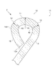
- the curled portion 10 provided in the mouth portion 1D of the can body 1 has a cross-sectional shape as shown in FIG. 2 (in the drawing, P1 is an imaginary line parallel to the can axis) ). That is, the curled portion 10 has an upper end curved portion 11 including the upper end of the mouth portion 1D, and a lower end 12A approaching or contacting the side wall 2 of the mouth portion 1D, and the upper side is inclined outward with respect to the can axis (virtual line P1).
- the cross-sectional shape of the outer wall curved portion 12 is a substantially inverted triangular shape having the side wall 2, the upper end curved portion 11, and the outer wall curved portion 12 of the mouth 1 ⁇ / b> D as three sides.
- Such a cross-sectional shape of the curled portion 10 is structurally resistant to drop impact.
- an inner connecting curved portion 13 is provided on the inner side of the upper end curved portion 11, and an outer connecting curved portion 14 is provided on the outer side of the upper end curved portion 11.
- the curvature radius R2 and the curvature radius R3 of the outer connecting curved portion 14 are both formed smaller than the curvature radius R1 of the upper end curved portion 11 to form a substantially inverted triangular corner.
- the side wall 2 of the mouth portion 1D above the lower end 12A of the outer wall curved portion 12 is inclined upward inward with respect to the can axis (virtual line P1).
- the curled portion 10 having such a cross-sectional shape has high resistance to the uneven load. have.
- the curled portion 10 is preferably formed so that the curvature radii of the upper end curved portion 11 and the outer wall curved portion 12 are substantially equal. According to this, the substantially inverted triangular shape due to the cross-sectional shape of the curled portion 10 becomes a substantially regular triangle, and has equal resistance to impact loads received from various directions. At this time, the outer connecting curved portion 14 becomes the maximum outer diameter portion 14 ⁇ / b> A in the curled portion 10.
- FIG. 3 shows an example of the sealing structure of the curled portion 10 when the cap 3 is attached to the mouth portion 1D of the can 1.
- the curled portion 10 having the above-described cross-sectional shape forms a seal point by the outer connecting curved portion 14 biting into the sealing material (liner material) 3A of the cap 3 when the cap 3 is attached to the mouth portion 1D. And good sealability can be obtained.
- the radius of curvature R3 of the outer connecting curved portion 14 to be smaller than the radius of curvature R1 of the upper-end curved portion 11 and setting it within an appropriate range, a curl that provides desired biting while preventing damage to the sealing material 3A is obtained.
- the shape of the part 10 can be obtained.
- the cap 3 when the can body 1 is in a positive pressure state, the cap 3 is always subjected to a force to move away from the upper end of the mouth portion 1D. However, according to the cross-sectional shape of the curled portion 10, it becomes a seal point. Since the outer wall curved portion 12 that extends downward from the outer connecting curved portion 14 is inclined inward, the lower portion of the outer connecting curved portion 14 that bites into the sealing material 3A lifts the cap 3 by positive pressure. It has a locking action to stop, and an effective sealing effect can be obtained even when the can body is in a positive pressure state.
- FIG. 4 shows an example of a method for forming the curled portion 10.
- A has shown opening end 1D1 before a process.
- Spinning molding as shown in (b) and (c) is performed on the opening end 1D1 as the first stage processing.
- a curved flange molding is performed on the opening end 1D1 by pressing the first spinning die 20 from above.
- the curved shape (curvature radius R ⁇ b> 1) of the upper end curved portion 11 in the curled portion 10 is formed by the curved mold 20 ⁇ / b> A of the first spinning die 20.
- the inner connecting curved portion 13 formed inside the upper end curved portion 11 is formed by pressing the second spinning die 21.
- the bending shape (curvature radius R2) of the inner connecting bending portion 13 is formed by the bending die 21A of the second spinning die 21.
- the remodeling tool 22 is pressed from the side and crushed as the second stage.
- the outer wall curved portion 12 which is a portion below the maximum outer diameter portion of the curled portion 10 is curved.
- the remodeling tool 22 has a mold surface 22A that is curved so that the upper side is inclined outward with respect to the rotation center axis. Therefore, a part of the outer wall curved portion 12 formed thereby is crushed.
- the revolving tool 22 has a curved molding surface whose lower side is inclined inward with respect to the rotation center axis and the can axis (virtual line P1).
- the curled portion 10 is formed by a combination of spinning forming and crushing processing as shown in the related art.
- a remodeling tool used in crushing processing is used.
- the 22 mold surfaces 22A are curved surfaces whose upper side is inclined outward with respect to the rotation center axis.
- 1 can body, 1A: bottom, 1B: trunk, 1C: shoulder, 1D: mouth, 2: side wall, 3: cap, 3A: sealing material, 10: curled portion, 11: upper end curved portion, 12: outer wall curved portion, 12A: lower end, 13: Inner connecting curved part, 14: Outer connecting curved part
Landscapes
- Engineering & Computer Science (AREA)
- Ceramic Engineering (AREA)
- Mechanical Engineering (AREA)
- Containers Having Bodies Formed In One Piece (AREA)
Abstract
キャップ被着に対して所望の密封性能を得ることができるカール部の形状であって、しかも落下衝撃に対するカール部の変形を抑止する。缶体1のカール部10は、口部1Dの上端を含む上端湾曲部11と、下端12Aが口部1Dの側壁2に近接又は当接して上方が缶軸に対して外側に傾斜した外壁湾曲部12と、上端湾曲部11の内側に設けられ、上端湾曲部11の曲率半径より小さい曲率半径を有する内側連結湾曲部13と、上端湾曲部11の外側に設けられ上端湾曲部11の曲率半径より小さい曲率を有する外側連結湾曲部14とを有する。
Description
本発明は、缶体及び缶体口部のカール部形成方法に関するものである。
口部を有する缶体は、飲料水などの液体収容物の容器として一般に用いられており、キャップで密封される口部には、開口端をカール状に巻き加工したカール部が形成されている。特に、ボトル缶は、アルミニウム製やその合金製の金属板を絞り加工及びしごき加工によって有底筒状体に形成した後、この有底筒状体の開口部に、ネックイン加工を施すことで縮径した口部を形成し、その口部にねじ成形加工とカール成形加工を施している。
このような缶体の口部に形成されるカール部は、口部に被着されるキャップのシール材との密封性などを考慮して、各種の加工形状が提案されている。
例えば、下記特許文献1に記載された従来技術は、開口部の周縁を径方向外側に折り返して形成されるカール部が、ボトル缶の缶軸方向と略平行な方向に延在した外面側壁部と、外面側壁部の上端から径方向内方に向かう外面側凸曲部と、外面側凸曲部からさらに径方向内方に向かう内面側凸曲部を備え、外面側壁部を所定長さ以上にすると共に、潰し加工によって直線状に成形される外面側壁部と外面側凸曲部との接続部を、ボトル缶の上端(口部の上端)から離間させた形状にしたものが示されている。
また、下記特許文献2に記載された従来技術は、外巻きのカール部を、カール潰し加工を施すことなく、その外側面が外方に突出する曲面となるようにし、カール部の縦断面形状が縦長の長円形となるように形成したものが示されている。
前述した特許文献1に記載の従来技術は、湾曲状のフランジ加工(スピニング成形)と直線的な潰し加工の組み合わせによってカール部を形成している。この際、直線的な潰し加工によって形成される外面側壁部の下端は自由端になっており、ボトル缶の口部(口金部)の外周面との間に比較的大きな間隙が形成されている。このような従来技術によると、缶体に収容物を充填した後キャップによって口部を密封した状態で、落下衝撃が加わった場合に、外面側壁部の下端と口部外周面との間隙に応じてカール部が変形することになり、この変形でシールポイントにおいて所望の密封性が得られなくなる問題が生じることがある。
これに対して、前述した特許文献2に記載の従来技術は、潰し加工を行うこと無く全体的に湾曲したカール部を形成しており、カール部の下端を口部の外周面に近接させている。しかしながら、横断面形状が縦長の長円形であるカール部は、その形状が落下衝撃に対して耐性のある形状になっていないので、缶体に収容物を充填した後キャップによって口部を密封した状態で、落下衝撃が加わった場合には、カール部の断面形状が潰れるように変形して、この変形により所望の密封性能が得られなく問題が生じることがある。
本発明は、このような従来技術の問題点を解消することを課題とするものであり、キャップ被着に対して所望の密封性能を得ることができるカール部の形状であって、しかも、落下衝撃に対するカール部の変形を抑止すること、が本発明の課題である。
このような課題を解決するために、本発明による缶体は、以下の構成を具備するものである。
口部を有し、前記口部の開口端にカール部を設けた缶体であって、前記カール部は、前記口部の上端を含む上端湾曲部と、下端が前記口部の側壁に近接又は当接して上方が缶軸に対して外側に傾斜した外壁湾曲部と、前記上端湾曲部の内側に設けられ、前記上端湾曲部の曲率半径より小さい曲率半径を有する内側連結湾曲部と、前記上端湾曲部の外側に設けられ前記上端湾曲部の曲率半径より小さい曲率を有する外側連結湾曲部とを有することを特徴とする缶体。
また、本発明による缶体口部のカール部形成方法は、底部と胴部と肩部と口部を有する缶体の、前記口部の開口端にカール部を形成する方法であって、前記カール部の最大外径部より下方の部位を潰し加工によって湾曲成形したことを特徴とする。
口部を有し、前記口部の開口端にカール部を設けた缶体であって、前記カール部は、前記口部の上端を含む上端湾曲部と、下端が前記口部の側壁に近接又は当接して上方が缶軸に対して外側に傾斜した外壁湾曲部と、前記上端湾曲部の内側に設けられ、前記上端湾曲部の曲率半径より小さい曲率半径を有する内側連結湾曲部と、前記上端湾曲部の外側に設けられ前記上端湾曲部の曲率半径より小さい曲率を有する外側連結湾曲部とを有することを特徴とする缶体。
また、本発明による缶体口部のカール部形成方法は、底部と胴部と肩部と口部を有する缶体の、前記口部の開口端にカール部を形成する方法であって、前記カール部の最大外径部より下方の部位を潰し加工によって湾曲成形したことを特徴とする。
このような特徴を有する本発明の缶体は、カール部の断面形状が落下衝撃に対する耐性を有する形状になっている。これによって、口部に被着するキャップに対して所望の密封性能を得ることができるカール部の形状であって、しかも落下衝撃に対するカール部の変形を抑止することができる。
また、本発明のカール部形成方法により、缶体カール部の最大外径部より下方の部位を、落下衝撃に対する耐性を有する形状、あるいは、口部に被着するキャップに対して所望の密封性能を得ることができる形状に成形できる。
また、本発明のカール部形成方法により、缶体カール部の最大外径部より下方の部位を、落下衝撃に対する耐性を有する形状、あるいは、口部に被着するキャップに対して所望の密封性能を得ることができる形状に成形できる。
以下、図面を参照して本発明の実施形態を説明する。以下の説明で、異なる図における同一符号は同一機能の部位を示しており、各図における重複説明は適宜省略する。
図1は、缶体1の構成例を示している。缶体1は、例えば、底部1A、胴部1B、肩部1C、口部1Dを有する金属製の容器である。缶体1の一例はボトル缶である。ボトル缶の形成方法は以下の通りである。例えば、アルミ合金などからなる金属板を円形状に打ち抜き、それを絞り加工して有底円筒状のカップ部材を得て、それを再絞り・しごき加工して、所定肉厚の円筒状の缶を一旦得る。その後、ネックイン加工によって、円筒状の缶の開口端から所定長さを縮径して肩部1Cおよび口部を形成する。そして口部に、ビード部及びネジ部をスピニング加工によって形成し、次いで、ネジ部の上方に、上向き内側に傾斜した側壁(後述の側壁2)をネックイン加工によって形成し、そして、前記側壁の上方の開口端には以下に説明するカール部10をスピニング加工により形成することで口部1Dを有するボトル形状の缶体1を得る。
カール部10は、口部1Dの開口端を外側に湾曲させてカール状に加工した部位である。カール部10は、口部1Dの周囲に略同一断面で環状に形成されている。
本発明の実施形態に係る缶体1の口部1Dに設けたカール部10は、図2に示すような断面形状を有している(図において、P1は缶軸に平行な仮想線である)。すなわち、カール部10は、口部1Dの上端を含む上端湾曲部11と、下端12Aが口部1Dの側壁2に近接又は当接して上方が缶軸(仮想線P1)に対して外側に傾斜した外壁湾曲部12とを有しており、その断面形状が、口部1Dの側壁2と上端湾曲部11と外壁湾曲部12を三辺とする略逆三角形状になっている。
このようなカール部10の断面形状は、構造的に落下衝撃に対する耐性を有する形状になっている。具体的な構造を示すと、上端湾曲部11の内側には内側連結湾曲部13が設けられ、上端湾曲部11に外側には外側連結湾曲部14が設けられており、内側連結湾曲部13の曲率半径R2と外側連結湾曲部14の曲率半径R3は、いずれも上端湾曲部11の曲率半径R1より小さく形成されて、略逆三角形状の角部を形成している。
また、更に具体的には、カール部10は、外壁湾曲部12の下端12Aより上側の口部1Dの側壁2が、缶軸(仮想線P1)に対して上方が内側に傾斜している。このように口部1Dの側壁2を傾斜させることで、この傾斜で図示F方向の偏荷重を受けることができるので、このような断面形状のカール部10は、偏荷重に対しても高い耐性を有している。
また、更に具体的には、カール部10は、上端湾曲部11と外壁湾曲部12の曲率半径が略同等に形成されることが好ましい。これによると、カール部10の断面形状による略逆三角形状が略正三角形になり、各種方向から受ける衝撃荷重に対して等しい耐性を有することになる。この際には、外側連結湾曲部14がカール部10における最大外径部14Aになる。
図3は、缶体1の口部1Dにキャップ3を被着した場合におけるカール部10の密封構造の一例を示している。前述した断面形状を有するカール部10は、キャップ3を口部1Dに被着した場合に、外側連結湾曲部14がキャップ3のシール材(ライナー材)3Aに食い込むことでシールポイントを形成することができ、良好な密封性を得ることができる。この際、外側連結湾曲部14の曲率半径R3を上端湾曲部11の曲率半径R1より小さくして、適正な範囲で設定することにより、シール材3Aの破損を防ぎながら所望の食い込みが得られるカール部10の形状にすることができる。
また、缶体1が陽圧状態の場合には、キャップ3に口部1Dの上端から離れようとする力が常に作用することになるが、カール部10の断面形状によると、シールポイントとなる外側連結湾曲部14から下方に延びる外壁湾曲部12が、内側に向けて傾斜しているので、シール材3Aに食い込んだ外側連結湾曲部14から下側の部分が陽圧によるキャップ3の浮き上がりを止める係止作用を有することになり、缶体が陽圧状態の場合にも効果的な密封効果を得ることができる。
図4は、カール部10の形成方法の一例を示している。(a)は、加工前の開口端1D1を示している。この開口端1D1に対して、第1段階の加工として、(b),(c)に示すようなスピニング成形を行う。具体的には、(b)に示すように、上方から第1のスピニングダイ20を押圧させることで、開口端1D1に湾曲状のフランジ成形(スピニング成形)を行う。この際、第1のスピニングダイ20の湾曲型20Aによって、カール部10における上端湾曲部11の湾曲形状(曲率半径R1)が成形される。次に、(c)に示すように、第2のスピニングダイ21を押圧させることで、上端湾曲部11の内側に形成される内側連結湾曲部13を成形する。この際、第2のスピニングダイ21の湾曲型21Aによって、内側連結湾曲部13の湾曲形状(曲率半径R2)が成形される。
その後、第2段階の加工として、(d)に示すように、リフォームツール22を側方から押し当てて、潰し加工する。この潰し加工で、カール部10の最大外径部より下方の部位である外壁湾曲部12を湾曲成形する。この際、リフォームツール22は、回転中心軸に対して上方が外側に傾斜して湾曲した型面22Aを有しているので、これによって成形される外壁湾曲部12は、その一部が潰し加工により、リフォームツール22の回転中心軸、および、缶軸(仮想線P1)に対し下方が内側に傾斜した湾曲成形面を有している。
このように、スピニング成形と潰し加工の組み合わせでカール部10を成形すること自体は、従来技術で示すように既に知られているが、本発明の形成方法では、潰し加工にて用いられるリフォームツール22の型面22Aが回転中心軸に対して上方が外側に傾斜した湾曲面であることが1つの特徴になっている。このようなリフォームツール22を用いることで、カール部10の断面形状を、落下衝撃に対して耐性を有する効果的な略逆三角形状にすることができる。
以上、本発明の実施の形態について図面を参照して詳述してきたが、具体的な構成はこれらの実施の形態に限られるものではなく、本発明の要旨を逸脱しない範囲の設計の変更等があっても本発明に含まれる。また、上述の各実施の形態は、その目的及び構成等に特に矛盾や問題がない限り、互いの技術を流用して組み合わせることが可能である。
1:缶体,1A:底部,1B:胴部,1C:肩部,1D:口部,
2:側壁,3:キャップ,3A:シール材,
10:カール部,11:上端湾曲部,12:外壁湾曲部,12A:下端,
13:内側連結湾曲部,14:外側連結湾曲部
2:側壁,3:キャップ,3A:シール材,
10:カール部,11:上端湾曲部,12:外壁湾曲部,12A:下端,
13:内側連結湾曲部,14:外側連結湾曲部
Claims (8)
- 口部を有し、前記口部の開口端にカール部を設けた缶体であって、
前記カール部は、
前記口部の上端を含む上端湾曲部と、
下端が前記口部の側壁に近接又は当接して上方が缶軸に対して外側に傾斜した外壁湾曲部と、
前記上端湾曲部の内側に設けられ、前記上端湾曲部の曲率半径より小さい曲率半径を有する内側連結湾曲部と、
前記上端湾曲部の外側に設けられ前記上端湾曲部の曲率半径より小さい曲率を有する外側連結湾曲部とを有することを特徴とする缶体。 - 前記カール部の断面形状は、前記口部の側壁と前記上端湾曲部と前記外壁湾曲部を三辺とする略逆三角形状であることを特徴とする請求項1記載の缶体。
- 前記外壁湾曲部の下端より上側の前記口部の側壁は、缶軸に対して上方が内側に傾斜していることを特徴とする請求項1又は2記載の缶体。
- 前記上端湾曲部と前記外壁湾曲部の曲率半径が略同等であることを特徴とする請求項1~3のいずれか1項に記載の缶体。
- 前記外側連結湾曲部が前記カール部における最大外径部となることを特徴とする請求項1~4のいずれか1項に記載の缶体。
- 底部と胴部と肩部と口部を有する缶体の、前記口部の開口端にカール部を形成する方法であって、
前記カール部の最大外径部より下方の部位を潰し加工によって湾曲成形したことを特徴とする缶体口部のカール部形成方法。 - 前記潰し加工によって湾曲成形された成形面が缶軸に対して下方が内側に傾斜して成形されることを特徴とする請求項6に記載された缶体口部のカール部形成方法。
- 第1段階の加工として前記口部の開口端にスピニングダイによる湾曲フランジ成形を行い、その後の第2段階として前記潰し加工を行うことを特徴とする請求項6又は7に記載された缶体口部のカール部形成方法。
Applications Claiming Priority (2)
| Application Number | Priority Date | Filing Date | Title |
|---|---|---|---|
| JP2016-089352 | 2016-04-27 | ||
| JP2016089352A JP6946620B2 (ja) | 2016-04-27 | 2016-04-27 | 缶体及び缶体口部のカール部形成方法 |
Publications (1)
| Publication Number | Publication Date |
|---|---|
| WO2017187899A1 true WO2017187899A1 (ja) | 2017-11-02 |
Family
ID=60161508
Family Applications (1)
| Application Number | Title | Priority Date | Filing Date |
|---|---|---|---|
| PCT/JP2017/013904 Ceased WO2017187899A1 (ja) | 2016-04-27 | 2017-04-03 | 缶体及び缶体口部のカール部形成方法 |
Country Status (3)
| Country | Link |
|---|---|
| JP (2) | JP6946620B2 (ja) |
| TW (1) | TW201738013A (ja) |
| WO (1) | WO2017187899A1 (ja) |
Cited By (1)
| Publication number | Priority date | Publication date | Assignee | Title |
|---|---|---|---|---|
| JP2019112081A (ja) * | 2017-12-22 | 2019-07-11 | ユニバーサル製缶株式会社 | ボトル缶、キャップ付きボトル缶及びボトル缶の製造方法 |
Families Citing this family (5)
| Publication number | Priority date | Publication date | Assignee | Title |
|---|---|---|---|---|
| JP6946620B2 (ja) * | 2016-04-27 | 2021-10-06 | 東洋製罐株式会社 | 缶体及び缶体口部のカール部形成方法 |
| WO2019073754A1 (ja) | 2017-10-10 | 2019-04-18 | 株式会社古河テクノマテリアル | Ti-Ni系合金、これを用いた線材、通電アクチュエータ及び温度センサ並びにTi-Ni系合金材の製造方法 |
| JP7447443B2 (ja) * | 2018-12-04 | 2024-03-12 | アルテミラ製缶株式会社 | 缶体 |
| TWI712457B (zh) * | 2019-01-04 | 2020-12-11 | 三能食品器具股份有限公司 | 烘焙烤盤的捲緣空包成型方法 |
| JP2024087463A (ja) * | 2022-12-19 | 2024-07-01 | 大和製罐株式会社 | キャップ付きボトル型缶の開口カール部の成形方法 |
Citations (5)
| Publication number | Priority date | Publication date | Assignee | Title |
|---|---|---|---|---|
| JP2003252321A (ja) * | 2002-02-27 | 2003-09-10 | Mitsubishi Materials Corp | ボトル缶の口部構造 |
| JP2004154862A (ja) * | 2002-09-12 | 2004-06-03 | Daiwa Can Co Ltd | 金属缶の開口カール部成形方法 |
| JP2004224417A (ja) * | 2003-01-27 | 2004-08-12 | Daiwa Can Co Ltd | 金属缶の開口カール部およびその製造方法 |
| JP2006188279A (ja) * | 2005-01-07 | 2006-07-20 | Daiwa Can Co Ltd | ピルファープルーフキャップ付き缶容器 |
| JP2013227083A (ja) * | 2009-04-06 | 2013-11-07 | Takeuchi Press Ind Co Ltd | 金属ボトル缶 |
Family Cites Families (8)
| Publication number | Priority date | Publication date | Assignee | Title |
|---|---|---|---|---|
| US5669259A (en) * | 1993-10-21 | 1997-09-23 | Stodd; Ralph P. | Apparatus for high speed production of shells for beverage containers |
| GB9702475D0 (en) * | 1997-02-07 | 1997-03-26 | Metal Box Plc | Can ends |
| JP4325818B2 (ja) * | 1999-06-29 | 2009-09-02 | 大和製罐株式会社 | ネジ付き缶 |
| JP3521402B2 (ja) * | 1999-11-26 | 2004-04-19 | 武内プレス工業株式会社 | 高い密閉性を保持できるねじ付金属缶 |
| KR101020379B1 (ko) * | 2006-04-17 | 2011-03-08 | 도요 세이칸 가부시키가이샤 | 금속제 캔 |
| US7503741B2 (en) * | 2007-01-16 | 2009-03-17 | Omnitech International, Inc. | Formation of a curl in a unitary closable container |
| JP5038934B2 (ja) * | 2008-02-22 | 2012-10-03 | 日本クラウンコルク株式会社 | 容器と容器蓋との組合せ |
| JP6946620B2 (ja) * | 2016-04-27 | 2021-10-06 | 東洋製罐株式会社 | 缶体及び缶体口部のカール部形成方法 |
-
2016
- 2016-04-27 JP JP2016089352A patent/JP6946620B2/ja active Active
-
2017
- 2017-03-31 TW TW106111056A patent/TW201738013A/zh unknown
- 2017-04-03 WO PCT/JP2017/013904 patent/WO2017187899A1/ja not_active Ceased
-
2021
- 2021-09-08 JP JP2021146097A patent/JP7363870B2/ja active Active
Patent Citations (5)
| Publication number | Priority date | Publication date | Assignee | Title |
|---|---|---|---|---|
| JP2003252321A (ja) * | 2002-02-27 | 2003-09-10 | Mitsubishi Materials Corp | ボトル缶の口部構造 |
| JP2004154862A (ja) * | 2002-09-12 | 2004-06-03 | Daiwa Can Co Ltd | 金属缶の開口カール部成形方法 |
| JP2004224417A (ja) * | 2003-01-27 | 2004-08-12 | Daiwa Can Co Ltd | 金属缶の開口カール部およびその製造方法 |
| JP2006188279A (ja) * | 2005-01-07 | 2006-07-20 | Daiwa Can Co Ltd | ピルファープルーフキャップ付き缶容器 |
| JP2013227083A (ja) * | 2009-04-06 | 2013-11-07 | Takeuchi Press Ind Co Ltd | 金属ボトル缶 |
Cited By (1)
| Publication number | Priority date | Publication date | Assignee | Title |
|---|---|---|---|---|
| JP2019112081A (ja) * | 2017-12-22 | 2019-07-11 | ユニバーサル製缶株式会社 | ボトル缶、キャップ付きボトル缶及びボトル缶の製造方法 |
Also Published As
| Publication number | Publication date |
|---|---|
| JP7363870B2 (ja) | 2023-10-18 |
| JP6946620B2 (ja) | 2021-10-06 |
| JP2021185100A (ja) | 2021-12-09 |
| JP2017197222A (ja) | 2017-11-02 |
| TW201738013A (zh) | 2017-11-01 |
Similar Documents
| Publication | Publication Date | Title |
|---|---|---|
| JP7363870B2 (ja) | 金属製の容器の製造方法 | |
| JP6515952B2 (ja) | ボトル缶、キャップ付きボトル缶、及びボトル缶の製造方法 | |
| JP3788371B2 (ja) | キャップ付ボトル缶及びボトル缶 | |
| JP2018177250A (ja) | 缶体及びその製造方法 | |
| TW201945249A (zh) | 具備瓶蓋之瓶型罐及其製造裝置 | |
| JP7496860B2 (ja) | ボトル缶体、キャップ付きボトル缶体、ボトル缶体のキャッピング方法 | |
| JP6817106B2 (ja) | ボトル型缶 | |
| JP7447443B2 (ja) | 缶体 | |
| JP6877943B2 (ja) | ボトル缶の製造方法 | |
| JP7103102B2 (ja) | ボトル缶、キャップ付きボトル缶、及びボトル缶の製造方法 | |
| WO2019039184A1 (ja) | ボトル缶及びキャップ付きボトル缶 | |
| JP7206046B2 (ja) | ボトル缶およびボトル缶の製造方法 | |
| JP6347337B1 (ja) | 金属製ボトルの製造方法 | |
| JP2023143990A (ja) | 缶体 | |
| JP5321774B2 (ja) | 密封容器蓋の製造方法及び密封容器蓋 | |
| JP7033857B2 (ja) | ボトル缶及びキャップ付きボトル缶 | |
| JP2019131265A (ja) | ボトル缶及びその製造方法 | |
| JP7494860B2 (ja) | ボトル缶およびボトル容器 | |
| JPH0327934Y2 (ja) | ||
| JP7220983B2 (ja) | ボトル缶、キャップ付きボトル缶 | |
| JP7262344B2 (ja) | ボトル缶 | |
| JP7072380B2 (ja) | ボトル缶の製造方法 | |
| JP2019011103A (ja) | ボトル缶及びキャップ付きボトル缶 | |
| JP2018104096A (ja) | ボトル缶およびキャップ付きボトル缶 | |
| JP2005280723A (ja) | ねじ付缶 |
Legal Events
| Date | Code | Title | Description |
|---|---|---|---|
| NENP | Non-entry into the national phase |
Ref country code: DE |
|
| 121 | Ep: the epo has been informed by wipo that ep was designated in this application |
Ref document number: 17789187 Country of ref document: EP Kind code of ref document: A1 |
|
| 122 | Ep: pct application non-entry in european phase |
Ref document number: 17789187 Country of ref document: EP Kind code of ref document: A1 |