WO2017187669A1 - Article absorbant - Google Patents
Article absorbant Download PDFInfo
- Publication number
- WO2017187669A1 WO2017187669A1 PCT/JP2017/001370 JP2017001370W WO2017187669A1 WO 2017187669 A1 WO2017187669 A1 WO 2017187669A1 JP 2017001370 W JP2017001370 W JP 2017001370W WO 2017187669 A1 WO2017187669 A1 WO 2017187669A1
- Authority
- WO
- WIPO (PCT)
- Prior art keywords
- longitudinal direction
- width direction
- excrement
- absorbent article
- absorber
- Prior art date
Links
Images


Classifications
-
- A—HUMAN NECESSITIES
- A61—MEDICAL OR VETERINARY SCIENCE; HYGIENE
- A61F—FILTERS IMPLANTABLE INTO BLOOD VESSELS; PROSTHESES; DEVICES PROVIDING PATENCY TO, OR PREVENTING COLLAPSING OF, TUBULAR STRUCTURES OF THE BODY, e.g. STENTS; ORTHOPAEDIC, NURSING OR CONTRACEPTIVE DEVICES; FOMENTATION; TREATMENT OR PROTECTION OF EYES OR EARS; BANDAGES, DRESSINGS OR ABSORBENT PADS; FIRST-AID KITS
- A61F13/00—Bandages or dressings; Absorbent pads
- A61F13/15—Absorbent pads, e.g. sanitary towels, swabs or tampons for external or internal application to the body; Supporting or fastening means therefor; Tampon applicators
- A61F13/53—Absorbent pads, e.g. sanitary towels, swabs or tampons for external or internal application to the body; Supporting or fastening means therefor; Tampon applicators characterised by the absorbing medium
- A61F13/534—Absorbent pads, e.g. sanitary towels, swabs or tampons for external or internal application to the body; Supporting or fastening means therefor; Tampon applicators characterised by the absorbing medium having an inhomogeneous composition through the thickness of the pad
- A61F13/537—Absorbent pads, e.g. sanitary towels, swabs or tampons for external or internal application to the body; Supporting or fastening means therefor; Tampon applicators characterised by the absorbing medium having an inhomogeneous composition through the thickness of the pad characterised by a layer facilitating or inhibiting flow in one direction or plane, e.g. a wicking layer
- A61F13/53708—Absorbent pads, e.g. sanitary towels, swabs or tampons for external or internal application to the body; Supporting or fastening means therefor; Tampon applicators characterised by the absorbing medium having an inhomogeneous composition through the thickness of the pad characterised by a layer facilitating or inhibiting flow in one direction or plane, e.g. a wicking layer the layer having a promotional function on liquid propagation in at least one direction
- A61F13/53717—Absorbent pads, e.g. sanitary towels, swabs or tampons for external or internal application to the body; Supporting or fastening means therefor; Tampon applicators characterised by the absorbing medium having an inhomogeneous composition through the thickness of the pad characterised by a layer facilitating or inhibiting flow in one direction or plane, e.g. a wicking layer the layer having a promotional function on liquid propagation in at least one direction the layer having a promotional function on liquid propagation in the horizontal direction
-
- A—HUMAN NECESSITIES
- A61—MEDICAL OR VETERINARY SCIENCE; HYGIENE
- A61F—FILTERS IMPLANTABLE INTO BLOOD VESSELS; PROSTHESES; DEVICES PROVIDING PATENCY TO, OR PREVENTING COLLAPSING OF, TUBULAR STRUCTURES OF THE BODY, e.g. STENTS; ORTHOPAEDIC, NURSING OR CONTRACEPTIVE DEVICES; FOMENTATION; TREATMENT OR PROTECTION OF EYES OR EARS; BANDAGES, DRESSINGS OR ABSORBENT PADS; FIRST-AID KITS
- A61F13/00—Bandages or dressings; Absorbent pads
- A61F13/15—Absorbent pads, e.g. sanitary towels, swabs or tampons for external or internal application to the body; Supporting or fastening means therefor; Tampon applicators
- A61F13/45—Absorbent pads, e.g. sanitary towels, swabs or tampons for external or internal application to the body; Supporting or fastening means therefor; Tampon applicators characterised by the shape
- A61F13/47—Sanitary towels, incontinence pads or napkins
- A61F13/472—Sanitary towels, incontinence pads or napkins specially adapted for female use
-
- A—HUMAN NECESSITIES
- A61—MEDICAL OR VETERINARY SCIENCE; HYGIENE
- A61F—FILTERS IMPLANTABLE INTO BLOOD VESSELS; PROSTHESES; DEVICES PROVIDING PATENCY TO, OR PREVENTING COLLAPSING OF, TUBULAR STRUCTURES OF THE BODY, e.g. STENTS; ORTHOPAEDIC, NURSING OR CONTRACEPTIVE DEVICES; FOMENTATION; TREATMENT OR PROTECTION OF EYES OR EARS; BANDAGES, DRESSINGS OR ABSORBENT PADS; FIRST-AID KITS
- A61F13/00—Bandages or dressings; Absorbent pads
- A61F13/15—Absorbent pads, e.g. sanitary towels, swabs or tampons for external or internal application to the body; Supporting or fastening means therefor; Tampon applicators
- A61F13/45—Absorbent pads, e.g. sanitary towels, swabs or tampons for external or internal application to the body; Supporting or fastening means therefor; Tampon applicators characterised by the shape
- A61F13/47—Sanitary towels, incontinence pads or napkins
- A61F13/475—Sanitary towels, incontinence pads or napkins characterised by edge leakage prevention means
- A61F13/4751—Sanitary towels, incontinence pads or napkins characterised by edge leakage prevention means the means preventing fluid flow in a transversal direction
- A61F13/4756—Sanitary towels, incontinence pads or napkins characterised by edge leakage prevention means the means preventing fluid flow in a transversal direction the means consisting of grooves, e.g. channels, depressions or embossments, resulting in a heterogeneous surface level
-
- A—HUMAN NECESSITIES
- A61—MEDICAL OR VETERINARY SCIENCE; HYGIENE
- A61F—FILTERS IMPLANTABLE INTO BLOOD VESSELS; PROSTHESES; DEVICES PROVIDING PATENCY TO, OR PREVENTING COLLAPSING OF, TUBULAR STRUCTURES OF THE BODY, e.g. STENTS; ORTHOPAEDIC, NURSING OR CONTRACEPTIVE DEVICES; FOMENTATION; TREATMENT OR PROTECTION OF EYES OR EARS; BANDAGES, DRESSINGS OR ABSORBENT PADS; FIRST-AID KITS
- A61F13/00—Bandages or dressings; Absorbent pads
- A61F13/15—Absorbent pads, e.g. sanitary towels, swabs or tampons for external or internal application to the body; Supporting or fastening means therefor; Tampon applicators
- A61F13/45—Absorbent pads, e.g. sanitary towels, swabs or tampons for external or internal application to the body; Supporting or fastening means therefor; Tampon applicators characterised by the shape
- A61F13/47—Sanitary towels, incontinence pads or napkins
- A61F13/476—Sanitary towels, incontinence pads or napkins characterised by encircling the crotch region of the undergarment
-
- A—HUMAN NECESSITIES
- A61—MEDICAL OR VETERINARY SCIENCE; HYGIENE
- A61F—FILTERS IMPLANTABLE INTO BLOOD VESSELS; PROSTHESES; DEVICES PROVIDING PATENCY TO, OR PREVENTING COLLAPSING OF, TUBULAR STRUCTURES OF THE BODY, e.g. STENTS; ORTHOPAEDIC, NURSING OR CONTRACEPTIVE DEVICES; FOMENTATION; TREATMENT OR PROTECTION OF EYES OR EARS; BANDAGES, DRESSINGS OR ABSORBENT PADS; FIRST-AID KITS
- A61F13/00—Bandages or dressings; Absorbent pads
- A61F13/15—Absorbent pads, e.g. sanitary towels, swabs or tampons for external or internal application to the body; Supporting or fastening means therefor; Tampon applicators
- A61F13/53—Absorbent pads, e.g. sanitary towels, swabs or tampons for external or internal application to the body; Supporting or fastening means therefor; Tampon applicators characterised by the absorbing medium
- A61F13/531—Absorbent pads, e.g. sanitary towels, swabs or tampons for external or internal application to the body; Supporting or fastening means therefor; Tampon applicators characterised by the absorbing medium having a homogeneous composition through the thickness of the pad
- A61F13/532—Absorbent pads, e.g. sanitary towels, swabs or tampons for external or internal application to the body; Supporting or fastening means therefor; Tampon applicators characterised by the absorbing medium having a homogeneous composition through the thickness of the pad inhomogeneous in the plane of the pad
- A61F13/533—Absorbent pads, e.g. sanitary towels, swabs or tampons for external or internal application to the body; Supporting or fastening means therefor; Tampon applicators characterised by the absorbing medium having a homogeneous composition through the thickness of the pad inhomogeneous in the plane of the pad having discontinuous areas of compression
-
- A—HUMAN NECESSITIES
- A61—MEDICAL OR VETERINARY SCIENCE; HYGIENE
- A61F—FILTERS IMPLANTABLE INTO BLOOD VESSELS; PROSTHESES; DEVICES PROVIDING PATENCY TO, OR PREVENTING COLLAPSING OF, TUBULAR STRUCTURES OF THE BODY, e.g. STENTS; ORTHOPAEDIC, NURSING OR CONTRACEPTIVE DEVICES; FOMENTATION; TREATMENT OR PROTECTION OF EYES OR EARS; BANDAGES, DRESSINGS OR ABSORBENT PADS; FIRST-AID KITS
- A61F13/00—Bandages or dressings; Absorbent pads
- A61F13/15—Absorbent pads, e.g. sanitary towels, swabs or tampons for external or internal application to the body; Supporting or fastening means therefor; Tampon applicators
- A61F13/53—Absorbent pads, e.g. sanitary towels, swabs or tampons for external or internal application to the body; Supporting or fastening means therefor; Tampon applicators characterised by the absorbing medium
- A61F13/534—Absorbent pads, e.g. sanitary towels, swabs or tampons for external or internal application to the body; Supporting or fastening means therefor; Tampon applicators characterised by the absorbing medium having an inhomogeneous composition through the thickness of the pad
- A61F13/537—Absorbent pads, e.g. sanitary towels, swabs or tampons for external or internal application to the body; Supporting or fastening means therefor; Tampon applicators characterised by the absorbing medium having an inhomogeneous composition through the thickness of the pad characterised by a layer facilitating or inhibiting flow in one direction or plane, e.g. a wicking layer
- A61F13/5376—Absorbent pads, e.g. sanitary towels, swabs or tampons for external or internal application to the body; Supporting or fastening means therefor; Tampon applicators characterised by the absorbing medium having an inhomogeneous composition through the thickness of the pad characterised by a layer facilitating or inhibiting flow in one direction or plane, e.g. a wicking layer characterised by the performance of the layer, e.g. acquisition rate, distribution time, transfer time
-
- A—HUMAN NECESSITIES
- A61—MEDICAL OR VETERINARY SCIENCE; HYGIENE
- A61F—FILTERS IMPLANTABLE INTO BLOOD VESSELS; PROSTHESES; DEVICES PROVIDING PATENCY TO, OR PREVENTING COLLAPSING OF, TUBULAR STRUCTURES OF THE BODY, e.g. STENTS; ORTHOPAEDIC, NURSING OR CONTRACEPTIVE DEVICES; FOMENTATION; TREATMENT OR PROTECTION OF EYES OR EARS; BANDAGES, DRESSINGS OR ABSORBENT PADS; FIRST-AID KITS
- A61F13/00—Bandages or dressings; Absorbent pads
- A61F13/15—Absorbent pads, e.g. sanitary towels, swabs or tampons for external or internal application to the body; Supporting or fastening means therefor; Tampon applicators
- A61F13/53—Absorbent pads, e.g. sanitary towels, swabs or tampons for external or internal application to the body; Supporting or fastening means therefor; Tampon applicators characterised by the absorbing medium
- A61F13/534—Absorbent pads, e.g. sanitary towels, swabs or tampons for external or internal application to the body; Supporting or fastening means therefor; Tampon applicators characterised by the absorbing medium having an inhomogeneous composition through the thickness of the pad
- A61F13/537—Absorbent pads, e.g. sanitary towels, swabs or tampons for external or internal application to the body; Supporting or fastening means therefor; Tampon applicators characterised by the absorbing medium having an inhomogeneous composition through the thickness of the pad characterised by a layer facilitating or inhibiting flow in one direction or plane, e.g. a wicking layer
- A61F2013/53765—Absorbent pads, e.g. sanitary towels, swabs or tampons for external or internal application to the body; Supporting or fastening means therefor; Tampon applicators characterised by the absorbing medium having an inhomogeneous composition through the thickness of the pad characterised by a layer facilitating or inhibiting flow in one direction or plane, e.g. a wicking layer characterized by its geometry
- A61F2013/53778—Absorbent pads, e.g. sanitary towels, swabs or tampons for external or internal application to the body; Supporting or fastening means therefor; Tampon applicators characterised by the absorbing medium having an inhomogeneous composition through the thickness of the pad characterised by a layer facilitating or inhibiting flow in one direction or plane, e.g. a wicking layer characterized by its geometry with grooves
Definitions
- the present invention relates to an absorbent article.
- Patent Document 1 discloses a sanitary napkin 1 having an absorbent body 4 on which a dodd-like emboss 7 is formed. It is shown that the absorption performance is improved by the capillary action by the fiber density difference provided by the dodd-like emboss 7.
- the body fluid absorbed in the region H indicating the body fluid discharge site is transferred by capillary action, so that it is substantially concentric.
- the body fluid is diffused in a shape.
- the length in the longitudinal direction of the absorbent body 4 can be adjusted according to the application, but the length in the width direction depends on the length of the user's crotch. Since it is limited, the length in the width direction becomes shorter. Therefore, the body fluid diffused substantially concentrically may leak from the end of the absorbent body 4 in the width direction although the range that can be absorbed in the longitudinal direction is wide.
- the present invention has been made in view of the above problems, and an object thereof is to absorb excrement in a wider range of the absorber.
- the main invention for achieving the above object has a longitudinal direction, a width direction, and a thickness direction orthogonal to each other, and includes an absorbent body and a wing adhesive portion on each non-skin side of the thickness direction, An absorbent article having a pair of wings protruding outward in the width direction, wherein the absorbent body is recessed in the thickness direction in the central region of the absorbent body in the width direction, and in the longitudinal direction.
- a region where the excrement is present when absorbed by the body is defined as an excrement present region
- half of the length in the longitudinal direction of the excrement present region is the length in the width direction of the excrement present region.
- the value divided by is the front pressure of the absorber.
- the distance from the most front end in the longitudinal direction of the portion to the center in the longitudinal direction of the wing adhesive portion is equal to or greater than the value obtained by dividing by the length in the width direction of the absorber at the center.
- the absorbent article is characterized in that a central guiding part induces the excrement.
- excrement can be absorbed in a wider range of the absorber.
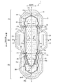
- FIG. 1 is a plan view of the napkin 1 as seen from the skin side.
- FIG. 2 is a plan view of the napkin 1 viewed from the non-skin side.
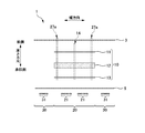
- FIG. 3 is a schematic sectional view taken along the line AA in FIG.
- FIG. 4 is a plan view of the absorbent body 10 as viewed from the non-skin side.
- FIG. 5 is an enlarged schematic view of the absorber point-like squeezed portion 15 when the absorber 10 is viewed from the skin side.
- FIG. 6A is a schematic cross-sectional view in which an absorbent dot-like compressed portion 15 is formed in the portion of the absorbent body 10 indicated by arrows EE in FIG. FIG.
- FIG. 6B is a schematic cross-sectional view in which a central guide portion 14 is formed in the absorber 10 of FIG. 6A.
- 6C is a schematic cross-sectional view in which the top sheet 3 is laminated on the absorbent body 10 of FIG. 6B.
- FIG. 6D is a schematic cross-sectional view of the napkin 1 at a portion indicated by arrows EE in FIG.
- FIG. 7 is a diagram illustrating a usage mode of the napkin 1.
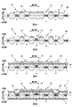
- Drawing 8A is a figure explaining an absorber which does not have an absorber point-like pressing part and a central guidance part.
- Drawing 8B is a figure explaining an absorber which has an absorber squeezing part and does not have a center guidance part.
- FIG. 8A is a figure explaining an absorber which does not have an absorber point-like pressing part and a central guidance part.
- Drawing 8B is a figure explaining an absorber which has an absorber squeezing part and does not have a center guidance part
- FIG. 8C is a diagram illustrating an absorbent body that does not have an absorbent point-like compressed portion and has a central guiding portion.
- Drawing 8D is a figure explaining an absorber which has an absorber point-like pressing part and a central guidance part.
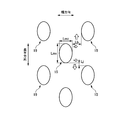
- FIG. 9 is a schematic diagram for explaining the excreta present region Q (q) when the napkin 1 absorbs excreta.
- FIG. 10A is a schematic diagram showing a state of the napkin 100 before use.
- FIG. 10B is a schematic diagram illustrating a state after a predetermined time has elapsed after a liquid is dropped on the napkin 100 of FIG. 10A.
- FIG. 10C is a schematic diagram showing a state after a predetermined time has elapsed after the liquid is dropped on the napkin 100 of FIG.
- FIG. 11A is a schematic diagram showing a state of the napkin 1 before use.
- FIG. 11B is a schematic diagram illustrating a state after a predetermined time has elapsed after a liquid is dropped on the napkin 1 of FIG. 11A.
- FIG. 11C is a schematic diagram showing a state after a predetermined time has elapsed after a liquid is dropped on the napkin 1 of FIG. 11A.
- FIG. 11D is a schematic diagram showing the maximum excreta existing region qm of the napkin 1.
- a pair of wing portions that have a longitudinal direction, a width direction, and a thickness direction orthogonal to each other, and each have a wing adhesive portion on the non-skin side in the thickness direction and project outward in the width direction.
- the absorbent body has a central guiding portion for inducing excrement, which is recessed in the thickness direction in the central region of the absorbent body in the width direction and along the longitudinal direction.
- the front region of the absorbent body in the longitudinal direction is recessed in the thickness direction and has a front compressed portion that intersects the longitudinal direction, and the excrement is present when the absorbent body absorbs
- the excrement present area is defined as the excrement present area
- a value obtained by dividing half of the length in the longitudinal direction of the excrement present area by the length in the width direction of the excrement present area is Front from the frontmost end in the longitudinal direction of the front compressed part
- the central guiding portion induces the excrement so that the distance to the center in the longitudinal direction of the wing adhesive portion is equal to or larger than the value obtained by dividing the distance in the width direction of the absorber in the center.
- the absorbent article is characterized.
- the excrement present area when the excrement reaches the foremost end in the longitudinal direction of the front compressed portion is the maximum excrement present area
- the maximum excrement present area A value obtained by dividing half of the length in the longitudinal direction by the length in the width direction of the maximum excreta present region is the wing adhesive from the frontmost end in the longitudinal direction of the front pressing portion of the absorber. It is preferable that it is the widest area
- Such an absorbent article can reduce the risk of excrement leaking from both ends of the absorbent body in the width direction even when the excrement has spread to the maximum excretion-existing region.
- the absorbent body is provided with at least a central region of the absorbent body in the longitudinal direction, and is provided with one side linear compressed portion and the other side linear compressed portion along the longitudinal direction,
- the one side linear pressing part is located between the one end of the absorber and the central guiding part in the width direction
- the other side linear pressing part is the absorber in the width direction.
- the excrement existing region is on the front side before reaching the outer end in the width direction of the one side linear compressed portion of the absorber and the outer end in the width direction of the other side linear compressed portion. Since excrement can be induced to reach the pressing part, excrement can be absorbed in a wider range of the absorber.
- Such an absorbent article wherein the absorbent article has a plurality of folding parts along the width direction for folding with the skin side face inward, and the absorbent body in the longitudinal direction
- the absorbent body In the rear region of the absorbent body, it has a rear pressing part that is recessed in the thickness direction and intersects the longitudinal direction, and the folding part is located in front of the wing adhesive part in the longitudinal direction, and the longitudinal direction.
- One or more are provided on the rear side in the direction, and the front pressing part is provided on the front side from the front folding part closest to the wing adhesive part among the folding parts located on the front side in the longitudinal direction.
- the said rear side pressing part is provided in the back side rather than the back side folding part nearest to the said wing adhesion part among the said folding parts located in the said rear side of the said longitudinal direction.
- the excrement induced along the longitudinal direction is provided on the front side by providing the front pressing part and the rear pressing part on the front side and the rear side in the longitudinal direction outside the folding part, respectively. Since it is guided in the width direction more in the squeezing part and the rear squeezing part, while reducing the excretion being induced to the outside in the longitudinal direction from the front squeezing part and the rear squeezing part, in a wider range of the absorber It can absorb excrement.
- the absorbent body has a linear rear side linear pressing portion that is recessed in the thickness direction and along the longitudinal direction in the rear region of the absorbent body in the longitudinal direction. It is preferable.
- the excrement since the excrement can be induced by the rear side linear pressing portion, the excrement is diffused further to the rear side, particularly in the case of an absorbent article having a longer rear side than the front side.
- the excrement can be absorbed in a wider range of the absorber.
- the absorbent body has at least one rear compressed portion that is recessed in the thickness direction and intersects the longitudinal direction in a rear region of the absorbent body in the longitudinal direction.
- the rear linear pressing portion is located between the rear end of the wing adhesive portion in the longitudinal direction and the rearmost end of the rear pressing portion located on the rearmost side. Preferably it is.
- the excrement induced by the rear linear pressing part can be diffused in the width direction by the rear pressing part, the excrement diffuses from the rear pressing part to the outside in the longitudinal direction. Can be reduced.
- a first pressing unit having a pair of the rear linear pressing unit and the rear pressing unit connected to each longitudinal end of the rear linear pressing unit, and a pair A second pressing portion having the other rear pressing portion connected to each end in the longitudinal direction of the other rear linear pressing portion, and the other rear pressing portion.
- the first squeezing part is located inside the second squeezing part.
- the excrement can be guided to the outside in the longitudinal direction by the rear linear pressing portion of the first pressing portion, and the width direction of the rear linear pressing portion of the first pressing portion. Even if excrement moves to the outer side of the stool, the risk of excrement leaking to the outside in the width direction of the absorbent body is reduced by the other rear linear pressing part of the second pressing part located outside. can do. Moreover, the excrement can be moved to the outer side in the width direction by the rear pressing unit of the first pressing unit, and the excrement has moved to the outer side in the longitudinal direction from the rear pressing unit of the first pressing unit. Even if it exists, the possibility that excrement will leak to the outer side of the longitudinal direction of an absorber can be reduced by the other back side compression part of the 2nd compression part located outside.
- the central guiding portion is provided from the front end to the rear end of the absorber, and the central guiding portion intersects with the front pressing portion and the rear pressing portion. It is preferable.
- the central guide portion is the front compressed portion and By crossing the rear side compressed part, the front side compressed part and the rear side compressed part can promote the guidance in the width direction at each crossed part, so that excrement diffuses outside in the longitudinal direction of the absorber. Can be reduced.
- the absorbent body has liquid absorbent fibers, and a plurality of point-like compressed parts recessed in the thickness direction are provided on both sides of the central guide part in the width direction.
- the density of the liquid absorbent fibers in the central guide portion is higher in the center portion than in the end portions, and the density of the liquid absorbent fibers in the point-like compressed portion is in the width direction.
- the central portion is higher than the end portion, and the central position of the central portion of the central guiding portion in the thickness direction is higher than the central position of the central portion of the point-like compressed portion in the thickness direction. It is preferably located on the skin side in the vertical direction.
- the absorbent body since the absorbent body is bent to the skin side by the central guiding portion, the absorbent body is brought into contact with the excretion opening such as the vagina mouth of the user. Is moved from the skin side to the non-skin side and moved to the point-like compressed portion, so that the touch of the surface in contact with the skin can be improved while improving the fit of the absorbent article.
- this absorbent article Comprising: Between the said center induction
- region of the liquid absorptive fiber which can store excrement stores the excrement absorbed in the center induction
- the density of the liquid absorbent fiber is higher in the central portion of the point-like compressed portion than in the central portion of the central guide portion.
- the excrement absorbed by the central guiding portion can be first guided to the point-like compressed portion having a higher liquid absorbent fiber.
- the length in the longitudinal direction of the point-like compressed portion is longer than the length in the width direction.
- the distance between the centers of the point-like compressed portions adjacent to each other in the width direction is uniform.
- FIG. 1 is a plan view of a sanitary napkin 1 (hereinafter referred to as “napkin 1”) as viewed from the skin side.
- FIG. 2 is a plan view of the napkin 1 viewed from the non-skin side.
- FIG. 3 is a schematic sectional view taken along the line AA in FIG.
- the napkin 1 has a longitudinal direction, a width direction, and a thickness direction that are orthogonal to each other.
- the side that contacts the lower abdomen of the wearer is referred to as “front side”, and the side that contacts the buttocks of the wearer is referred to as “rear side”.
- abuts a wearer among the thickness directions of the napkin 1 is called a "skin side”, and the other side is called a "non-skin side.”
- the XX line in the figure is the center line of the napkin 1 in the width direction.
- the top sheet 3, the absorber 10, and the back sheet 5 are laminated in order from the skin side in the thickness direction.
- Each member 3, 10, 5 is joined to a member adjacent in the thickness direction with an adhesive (not shown).
- the napkin 1 includes a napkin main body portion 20 provided with the absorbent body 10 and a pair of wing portions 30 extending from the longitudinal central region of the napkin main body portion 20 to both outer sides in the width direction.
- the top sheet 3 is a liquid-permeable sheet, and examples thereof include an air-through nonwoven fabric.
- the back sheet 5 is a liquid-impermeable sheet, and examples thereof include a polyethylene (PE) resin film.
- PE polyethylene
- a non-skin side surface (non-skin side surface of the back sheet 5) of the napkin main body 20 is provided with a main body adhesive section 21.
- the main body adhesive section 21 is affixed to the side of the skin such as underwear, whereby the napkin 1 is fixed to the underwear or the like.
- the adhesive section 21 for the main body shown in FIG. 2 has three rectangular adhesive sections having long sides in the longitudinal direction arranged at intervals in the longitudinal direction, and the row of the three adhesive sections in the width direction. Eight rows are arranged at intervals.
- a wing portion adhesive portion 31 is provided on the non-skin side surface of each wing portion 30 (the non-skin side surface of the back sheet 5).
- the wing portion 30 is bent toward the non-skin side, and the wing portion adhesive portion 31 is attached to the non-skin side surface such as underwear, whereby the napkin 1 is fixed to the underwear or the like.
- the wing adhesive portion 31 shown in FIG. 2 is a rectangular adhesive portion having a long side in the longitudinal direction.
- the absorbent body 10 is a member that absorbs excrement and holds it inside.
- the non-skin side sheet 13 is provided, and the members 11 to 13 are laminated in the thickness direction.
- the absorbent core 12 is formed in a vertically long shape in plan view (the broken line portion in FIG. 1), and a superabsorbent polymer (so-called SAP) that is a liquid absorbent granular material is added to pulp fibers that are liquid absorbent fibers.
- SAP superabsorbent polymer
- the basis weight composition ratio of the liquid absorbent fibers is about 90%
- the basis weight composition ratio of the SAP is about 10%.
- a liquid absorptive fiber a cellulose type absorptive fiber can be mentioned.
- the skin side sheet 11 is a liquid-permeable sheet, and can be exemplified by tissue paper and the like.
- the non-skin side sheet 13 may be a liquid-permeable sheet or a liquid-impermeable sheet, and examples thereof include an SMS (spunbond / meltblown / spunbond) nonwoven fabric.
- the absorbent core 12, the skin side sheet 11, and the non-skin side sheet 13 have substantially the same planar shape, and are adhesive (not shown) so as to cover the absorbent core 12 from the skin surface side and the non-skin surface side, respectively. (FIG. 3).
- the skin-side sheet 11 and the non-skin-side sheet 13 may have different planar shapes, and the members 11 to 13 may not be joined to each other by an adhesive.
- the napkin 1 has a front region R1, a central region R2, and a rear region R3 in order from the front side in the longitudinal direction (FIG. 1).
- the “front region R1” is a region in front of the portion where the wing portion 30 is provided, and is a region in front of the portion where the napkin 1 is most depressed in the width direction above the wing portion adhesive portion 31.
- the “rear region R3” is a region on the rear side of the portion where the wing portion 30 is provided, and is a region on the rear side of the portion where the napkin 1 is most depressed in the width direction behind the wing portion adhesive portion 31.
- a region between the front region R1 and the rear region B in the longitudinal direction and where the wing portion 30 is provided is referred to as a central region R2.
- the napkin 1 is folded in three with a front folded portion Ff located in the front region R1 and a rear folded portion Fb located in the rear region R3 and individually wrapped.
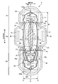
- FIG. 4 is a plan view of the absorbent body 10 as viewed from the non-skin side.
- FIG. 5 is an enlarged schematic view of the absorber point-like squeezed portion 15 when the absorber 10 is viewed from the skin side.
- the end along the longitudinal direction on both outer sides in the width direction is respectively the lateral end 10e
- the front curved end in the longitudinal direction is the front end 10et
- the rear curved end is This is referred to as a rear end 10eb.
- the absorber 10 is a so-called thin absorber having a thickness of 3 mm or less, preferably 2 mm or less, by the absorber point-like pressing part 15.
- the absorbent body 10 has a longitudinal direction between the front end 10et and the rear end 10eb, and a width direction between the lateral end 10e on one side and the lateral end 10et on the other side. It has a plurality of absorber spot-like pressing parts 15 arranged in a staggered pattern. Absorbent point squeezed portion 15 is recessed in the thickness direction from the skin side and the non-skin side. Moreover, the planar shape of the absorber squeezed compressed portion 15 is an ellipse having a longer length Lm1 in the longitudinal direction than the length Lm2 in the width direction (Lm1> Lm2), and promotes diffusion of excrement and the like in the longitudinal direction. ing.
- punctate pressing parts 15 adjacent to the width direction is equal, and the center gap
- Lb is shorter than the length Lm2 of the width direction of the absorber dot-shaped pressing part 15 between the edges of the absorber dot-shaped pressing parts 15 adjacent in the width direction (Lm2> Lb).
- the distance Lj between the edges of the absorber point-shaped compressed parts 15 adjacent in the longitudinal direction is shorter than the distance Lb between the edges of the absorber point-shaped compressed parts 15 adjacent in the width direction (Lj ⁇ Lb).
- the absorber 10 is provided with a central guiding portion 14 along the longitudinal direction at the central portion in the width direction.
- the center guiding portion 14 is recessed in the thickness direction from the skin side and the non-skin side from the front end 10et to the rear end 10eb of the absorbent body 10, respectively.
- the center guide part 14 guides the absorbent body 10 to bend toward the skin side in the thickness direction with the center guide part 14 as a base point, and guides excrement and the like in the longitudinal direction. The details of bending induction and excretion induction by the central guide 14 will be described later.
- the point-like pressing part 25 is a circular pressing part in which the top sheet 2 and the absorbent body 10 are pressed together in the thickness direction.
- the point-like pressing parts 25 are recessed in the thickness direction from the skin surface side, and the pressing parts 26, 27, and 28 described later are provided discretely in a substantially closed region partitioned on the top sheet 2.
- FIG. 6A to FIG. 6D are diagrams for explaining the formation of the central guiding portion 14, the absorber point-like pressing portion 15, and the point-like pressing portion 25.
- FIG. 6A is a schematic cross-sectional view in which an absorbent dot-like compressed portion 15 is formed in the portion of the absorbent body 10 indicated by arrows EE in FIG.
- FIG. 6B is a schematic cross-sectional view in which a central guide portion 14 is formed in the absorber 10 of FIG. 6A.
- 6C is a schematic cross-sectional view in which the top sheet 3 is laminated on the absorbent body 10 of FIG. 6B.
- FIG. 6D is a schematic cross-sectional view of the napkin 1 at a portion indicated by arrows EE in FIG.
- the yy line is the center line of the absorber 10 in the thickness direction
- YY in FIG. 6D is the center line of the napkin 1 in the thickness direction.
- punctate pressing part 25 are the roll gap
- the absorber squeezed compressed portion 15 is formed.
- the absorbent body 10 before processing is squeezed (embossed) from the non-skin surface side
- the absorber squeezed portion 15 is formed, and the squeezed region a is squeezed and recessed from the skin side and non-skin side.
- a region b is formed (FIG. 6A).
- the liquid absorbent fibers are crushed, the thickness is thinner than the region a, and the density of the liquid absorbent fibers is higher than the region a. That is, the density of the liquid absorbent fiber is higher in the center portion bc of the absorber point-like compressed portion 15 than in the end portion of the absorber point-like pressed portion 15 in the width direction.
- the absorber dotted compression part 15 is located in the approximate center part in the thickness direction of the absorber 10.
- the central guide portion 14 is formed.
- the central guiding portion 14 is subjected to shaping / squeezing from the non-skin surface side to the central portion in the width direction of the absorbent body of the absorbent body 10 in which the absorbent body point-like compressed portion 15 is formed, the central guiding portion 14 is formed.
- a region c newly recessed from the skin side and the non-skin side is formed (FIG. 6B).
- the liquid absorbent fibers are crushed, the thickness is thinner than the area a, and the density of the liquid absorbent fibers is higher than that of the area a, similarly to the absorbent point squeezed portion 15. That is, the density of the liquid absorbent fibers is higher in the central portion cc of the central guiding portion 14 than in the end portion of the central guiding portion 14 in the width direction.
- the density of a liquid absorptive fiber is higher in the central part bc of the absorbent body point-like compressed part 15 than in the central part cc of the central guiding part 14.
- This can be realized by performing the squeezing that forms the absorber point squeezed portion 15 with a larger pressure than the squeezing that forms the central guiding portion 14.
- induction part 14 can be first induced
- the thickness of the central guiding portion 14 is partially thinner, and the density of the liquid absorbent fibers is higher. Become.
- the top sheet 3 is laminated from the skin side of the absorbent body 10, and is fixed by an adhesive (HMA).
- HMA an adhesive
- the point-like pressing part 25 is formed.
- the top sheet 3 and the absorbent body 10 are squeezed together in the thickness direction from the skin surface side to form a newly recessed region d from the skin side (FIG. 6D).
- the back sheet 5 is laminated on the non-skin side and fixed with an adhesive to form the napkin 1.
- the liquid absorbent fibers are further crushed, the thickness is thinner than the region a, and the density of the liquid absorbent fibers is higher than the region a. That is, the density of the liquid absorbent fibers is higher in the central portion dc of the point-like compressed portion 25 than in the end portion of the point-like compressed portion 25 in the width direction.
- the point-like compressed portion 25 is located at a substantially central portion in the thickness direction of the napkin 1.
- punctate pressing part 25 was formed in the part in which the absorber dotted
- the napkin 1 is dented from the skin side in the thickness direction toward the non-skin side, and the linear compressed parts 26, 27, 28, 29 having a higher density of liquid absorbent fibers than the adjacent parts. Is provided.
- the top sheet 3 and the absorbent body are pressed (embossed) from the skin side in the thickness direction, and are integrally joined.
- the compression parts 26, 27, and 28 have a substantially annular shape that is long in the longitudinal direction as a whole, and the compression part 26, the compression part 27, and the compression part 28 are formed along the outer peripheral edge of the absorbent body 10. ing.
- the pressing part 26 is provided in the front side area
- the front squeezing part 26a is located on the foremost side, intersects the longitudinal direction, and generally follows the outer shape of the napkin 1 having a convex shape on the front side.
- Each end of the rear side of the front pressing part 26a and each end of the front side of the linear pressing part 26b are connected to each other, and the linear pressing part 26b is behind the front pressing part 26a and is behind the front pressing part 26a.
- the pressing part 27 is mainly provided in the central region R2, has a linear pressing part (one side linear pressing part, the other side linear pressing part) 27a and superimposed pressing parts 27b, 27c. It is a symmetric shape.
- the linear pressing part 27a is respectively provided along the longitudinal direction at both ends in the width direction of the absorber 10 in the central region R2, and the one side linear pressing part 27a is a lateral end on one side of the absorber 10. 10e and the center induction
- each linear compressed portion 27a is disposed at a position separated from the lateral end 10e by a predetermined distance (for example, 7 mm), and the width direction of each linear compressed portion 27a from the lateral end 10e. It is preferable that the distance to the outermost end of is 3 mm or more.
- the superimposed compressed portion 27b is provided in the front region R1 in front of the linear compressed portion 27a, is adjacent to the rear end portion of the linear compressed portion 26b from the outside in the width direction, and the width direction of the absorbent body 10 Is located at both ends.
- the superimposed compressed portion 27c is provided in the rear region R3 on the rear side of the linear compressed portion 27a, is adjacent to the front end of the linear compressed portion 28b (described later) from the outside in the width direction, and It is located at both ends in the width direction.
- each end of the rear side of the superimposed compressed portion 27b is connected to each end of the front side of the linear compressed portion 27a, and each end of the rear side of the linear compressed portion 27a and the front side of the superimposed compressed portion 27c. Each end of is connected.
- the pressing part (second pressing part) 28 is provided in the rear region R3, has a rear pressing part 28a and a linear pressing part 28b, and has a symmetrical shape with respect to the central guiding part 14.
- the rear squeezed portion 28a is located on the most rear side, intersects the longitudinal direction, and substantially follows the outer shape of the napkin 1.
- Each end on the front side of the rear compressed portion 28a is connected to each end on the rear side of the linear compressed portion 28b, and the linear compressed portion 28b is in front of the rear compressed portion 28a. It is provided from each front end of 28a to the front portion of the rear region R3.
- the pressing part 29 (first pressing part) is located in the rear region R ⁇ b> 3 and is provided on the inner side in the longitudinal direction and the width direction of the pressing part 28. Moreover, the pressing part 29 has the inner side pressing part 29a and the linear pressing part (rear side linear pressing part) 29b, and is a symmetrical shape about the center induction
- FIG. The inner pressing part 29a is in front of the rear pressing part 28a, has a convex shape on the rear side and intersects the longitudinal direction, and is shorter in the width direction than the rear pressing part 28a.
- each end of the lower side of the linear pressing part 29b and each end of the front side of the inner pressing part 29a are connected to each other, and each end on the rear side of the linear pressing part 29b and on the front side of the inner pressing part 29a. To the front portion of the rear region R3.
- the boundary between the front pressing part 26a and each linear pressing part 26b, the boundary between the linear pressing part 27a and each superimposed pressing part 27b, 27c, the rear pressing part 28a and each linear pressing part 28b The boundary, the inner pressing part 29a and each linear pressing part 29b are set for convenience, but are not limited thereto.
- the front pressing part 26a, the rear pressing part 28a, and the inner pressing part 29a only have to have a length straddling at least the central guiding part 14, and each linear pressing part 26b, each linear pressing part 28b, each linear pressing part. It suffices that at least a part of the portion 29b is along the longitudinal direction.
- the front pressing part 27a, the rear pressing part 28a, and the inner pressing part 29a may be a linear pressing part having a length straddling at least the central guiding part 14.
- each superimposition pressing part 27b, 27c does not necessarily need to be provided, there exists a possibility that excrement may leak from the part where folding operation
- the length and shape of each pressing part 26, 27, 28, 29 can be arbitrarily set.
- FIG. 7 is a diagram illustrating a usage mode of the napkin 1.
- the central guiding portion 14 has a shape along the longitudinal direction and is dented in the thickness direction by pressing to increase the density of the liquid-absorbing fibers, so that liquid such as excrement can be guided in the longitudinal direction. .
- the diffusibility of liquid such as excreta will be described.
- “Capillary phenomenon” is also referred to as “capillary phenomenon”, and means that the rise of the liquid level in the tube or the degree of effect is proportional to the surface tension of the liquid and inversely proportional to the inner diameter of the tube.
- the space between the fibers corresponds to a tube, and refers to a phenomenon in which liquid permeates through a narrow space between the fibers regardless of gravity or top / bottom / left / right. The narrower the is, the faster the liquid penetrates. In other words, the higher the density of the liquid absorbent fibers, the more the excreta diffuses.
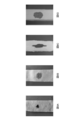
- 8A to 8D are absorbent bodies having a top sheet, an absorbent core, and a back sheet similarly to the absorbent body 10 of the present embodiment, and show a state after a predetermined amount of liquid has been dropped and a predetermined time has elapsed.
- the vertical direction of each drawing indicates the longitudinal direction
- the horizontal direction indicates the width direction.
- FIG. 8A is a diagram illustrating an absorbent body that does not have the absorbent body point-like compressed portion and the central guide portion.
- the dripped liquid is substantially concentric on the spot, and has almost remained at the dripped place.
- FIG. 8B is a diagram illustrating an absorbent body that has an absorbent point-like compressed portion and does not have a central guiding portion.
- the dropped liquid is urged between the adjacent absorbent point-like compressed parts by the capillary phenomenon of the absorbent point-like compressed part in which the density of the liquid absorbent fibers is increased, as compared with the case of FIG. 8A. Is also widespread.
- the liquid diffuses in the longitudinal direction and the width direction to the same extent, and diffuses substantially concentrically.
- FIG. 8C is a diagram illustrating an absorbent body that does not have an absorbent point-like compressed portion but has a central guiding portion. For this reason, the dropped liquid is promoted to diffuse along the central guiding portion due to the capillary phenomenon of the central guiding portion where the density of the liquid absorbent fibers is increased, and the diffusion of the liquid is not so advanced in the width direction. However, the liquid is diffused longer in the portion along the central guiding portion.
- FIG. 8D is a diagram illustrating an absorbent body having an absorbent spot-like compressed portion and a central guide portion.
- the phenomenon promotes liquid diffusion along the central guide. As a result, liquid diffusion is promoted both in the width direction and in the longitudinal direction.
- FIG. 8B when only the absorber squeezed portion is formed (FIG. 8B), the liquid has been diffused substantially concentrically, whereas the liquid is diffused by the central guide portion, so that the absorber squeezed portion is used.
- the liquid diffusing effect and the liquid diffusing effect by the central guiding portion are combined, and the region in which the liquid diffuses becomes a vertically long elliptical shape (FIG. 8D).
- Absorber squeeze-shaped compressed parts formed in the absorbent body at uniform intervals diffuse in the width direction and the longitudinal direction, and the range in which excrement and the like spreads is substantially concentric.
- the central guiding portion is formed along the longitudinal direction of the absorber, and diffuses the liquid in the longitudinal direction more.
- the central guiding portion can change the amount of liquid diffusion by changing the depth of depression (squeezing) of the central guiding portion, the length in the longitudinal direction, the area where the central guiding portion is formed, and the like.
- the central guide portion formed by higher pressure squeezing increases the density of the liquid absorbent fibers and can further promote the diffusion of the liquid in the longitudinal direction.
- the longer and wider central guiding portion has a larger area where the density of the liquid-absorbing fibers is high, so that it is possible to further promote the diffusion of the liquid in the longitudinal direction.
- a predetermined amount for example, 5 ml
- liquid such as artificial menstrual blood
- the central guiding portion can be adjusted according to the result.
- the central guiding portion may be squeezed more strongly or the width of the central guiding portion in the width direction may be increased.
- the liquid can also be diffused further outside in the longitudinal direction of the absorbent body by making the length of the central guiding portion in the longitudinal direction longer.
- the diffusibility of a liquid can also be improved by further increasing the ratio of a liquid absorptive fiber.
- the compression of the central guiding portion is weakened or the length of the central guiding portion in the width direction is short and formed in a narrow range Good.
- the diffusion of liquid can be adjusted more flexibly by combining not only the central guiding part but also the central guiding part and the point-like and linear pressing parts. What is necessary is just to observe the state similarly to adjustment of said center induction
- the central guide portion is formed by stronger squeezing to promote the diffusion in the longitudinal direction. You may reduce the spreading
- the number of the squeezed squeezed parts and the amount of squeezed parts can be set without changing the central guiding part. By increasing the number, diffusion in the width direction can be further promoted.
- the liquid diffusion in the longitudinal direction and the liquid diffusion in the width direction can be changed also by changing the density in the longitudinal direction of the point-like compressed portion and the density in the width direction of the point-like compressed portion. Can do.
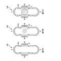
- FIG. 9 is a schematic diagram for explaining the excreta present region Q (q) when the napkin 1 absorbs excreta.
- the excreta present area Q is an area where excrement etc. exists when the absorbent body 10 of the napkin 1 absorbs excrement etc., and the excrement etc. can be recognized when the napkin 1 is viewed from the skin side.
- FIG. 9 schematically shows a state after the user has used the napkin 1 for a certain period of time and has absorbed a predetermined amount of excreta and the like.
- region Q does not necessarily exhibit a fixed shape, and has an irregular shape and a mottled color, in the following description, the oval shape circumscribed to the excrement existence area Q (Dotted line area
- the napkin 1 basically has the same configuration, but the napkin 100 that does not have the central guide portion 14 and the pressing portion 26 and the like, and the result obtained by dropping a predetermined amount of liquid on the napkin 1 of the present embodiment. Comparison will be described.
- Both the absorbent body 101 of the napkin 100 and the absorbent body 10 of the napkin 1 have a length in the longitudinal direction of about 285 mm and a length in the width direction of about 70 mm.
- the liquid dropped on the napkin 100 and the napkin 1 is a liquid such as colored water, and the napkin 100 and the center line XX in the width direction of the napkin 1 intersect with the wing adhesive portion center line WW. Dripping. And when the area
- FIG. 10A is a schematic diagram showing a state before the napkin 100 is used.
- the absorbent body 10 of the napkin 100 similarly to the napkin 1, has a plurality of absorbent point squeezed portions 15.
- FIG. 10B is a schematic diagram illustrating a state after a predetermined time has elapsed after a liquid is dropped on the napkin 100 of FIG. 10A.
- FIG. 10A shows a state where 0.5 ml of liquid is dropped on the napkin 100 in FIG. 10A and one hour has passed.
- the excreta present region q has a substantially concentric shape having a length T in the longitudinal direction and a length S in the width direction of about 30 mm, and is located inside the absorber 101.
- FIG. 10C is a schematic diagram showing a state after a predetermined time has elapsed after a liquid is dropped on the napkin 100 of FIG. 10A.
- FIG. 10A shows a state where 3.0 ml of liquid is dropped on the napkin 100 in FIG. 10A and one hour has passed.
- the excreta present region q is wider than the state of FIG. 10B, and has a substantially concentric shape with a length T in the longitudinal direction and a length S in the width direction of about 75 mm, and fits in the longitudinal direction of the absorbent body 101.
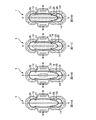
- the napkin 1 according to the present embodiment includes the central guide portion 14 and the pressing portions 26, 27, 28, and 29.
- FIG. 11A is a schematic diagram showing a state of the napkin 1 before use.
- the napkin 1 of this embodiment is a value ((T / 2) / S) obtained by dividing half (T / 2) of the length T in the longitudinal direction of the excreta present region q by the length S in the width direction.
- I is a value obtained by dividing the distance H from the front end 26ae of the front compressed portion 26a to the wing adhesive portion center line WW by the length K in the width direction of the absorbent body 10 at the wing adhesive portion center line WW ( H / K) or more ((T / 2) / S ⁇ H / K).
- the central guiding portion 14 that realizes (T / 2) / S ⁇ H / K can be formed by the following procedure. First, three types of napkins (squeezed portions 26, 27, 28, and 29 are the same, and the central guiding portion 14 is not formed) that differ only in the distribution density of the point-like compressed portions 25 are prepared. Next, for each napkin, the pressure is changed to squeeze the central guide portion 14 (the length is the same). Thereby, three types of napkins that differ only in the compressed state of the central guiding portion 14 are obtained.
- FIG. 11B is a schematic diagram illustrating a state after a predetermined time has elapsed after a liquid is dropped on the napkin 1 of FIG. 11A.
- FIG. 11A shows a state in which 0.5 ml of liquid has been dropped on the napkin 1 in FIG. 11A and one hour has elapsed.
- the excreta present region q has a vertically long elliptical shape with a length T of about 60 mm in the longitudinal direction and a length S of about 30 mm in the width direction, and is contained inside the absorber 10.
- FIG. 11C is a schematic diagram showing a state after a liquid has been dropped on the napkin 1 of FIG. 11A and a predetermined time has elapsed.
- the excreta present region q has a vertically long elliptical shape with a length T in the longitudinal direction of about 120 mm and a length S in the width direction of about 60 mm, and is contained inside the absorber 10.
- the napkin 1 of the present embodiment is configured so that the excrement and the like absorbed at the intersection of the center line XX of the absorbent body 10 and the wing adhesive portion center line WW
- the guiding portion 14 is diffused in the longitudinal direction rather than in the width direction.
- a value ((T / 2) / S) obtained by dividing half (T / 2) of the length T in the longitudinal direction of the excrement present region q by the length S in the width direction is the front end of the front compressed portion 26a.
- the distance H from 26ae to the wing adhesive part center line WW equal to or greater than the value (H / K) obtained by dividing the wing adhesive part center line WW by the length K in the width direction of the absorbent body 10 ( (T / 2) / S ⁇ H / K)
- the excreta present region q is accommodated inside the absorber 10, and the excrement is diffused over a wider range of the absorber 10 and absorbed. The risk of excrement leaking to the outside in the width direction of the body 10 is reduced.
- the excrement can be induced so that the excrement existing region q reaches the front pressing portion 26a before reaching the lateral end 10e of the absorber 10, and the absorber is more than the case of the absorber 101 of the napkin 100.
- Excrement etc. can be absorbed in 10 wider range.
- FIG. 11D is a schematic diagram showing the maximum excreta existing region qm of the napkin 1.
- the excrement existence region q when the diffused liquid reaches the front end 26ae of the front pressing portion 26a is referred to as a maximum excretion existence region qm, and the length of the excrement existence region qm in the longitudinal direction.
- a value obtained by dividing half of the length Tm (Tm / 2) by the length Sm in the width direction ((Tm / 2) / Sm) is a wing adhesive portion center line WW from the front end 26ae of the front compressed portion 26a.
- the maximum excreta present region qm has an asymmetric shape with respect to the wing adhesive portion center line WW in the longitudinal direction. That is, from the distance from the front end (front end 26ae of the front compressed portion 26a) to the wing adhesive portion center line WW to the maximum excrement presence region qm, the maximum excrement exists from the wing adhesive portion center line WW.
- the distance to the rear end of the region qm is longer. This is because each linear pressing part 28b, 29b provided in the rear region of the absorbent body 10 promotes the diffusion of excrement in the longitudinal direction. Since the napkin 1 is longer in the rear region R3 than in the front region R1, each linear squeezed portion 28b, 29b can promote the diffusion of the excrement to the rear region, and the maximum excrement existence region qm A wider area can be obtained.
- the one side linear pressing part 27a and the other side linear pressing part 27a along a longitudinal direction are provided, and the outer end of the width direction of each linear pressing part 27a is an outer end. 27ae.
- a value ((T / 2) / S) obtained by dividing half of the length T in the longitudinal direction of the excrement present area q by the length S in the width direction of the excrement present area q is the front side of the front compressed portion 26a.
- the napkin 1 has a plurality of folding portions Ff and Fb along the width direction for folding with the skin surface side inward, and the absorbent body 10 is thicker in the rear region of the absorbent body 10. It has a rear squeezing part 28a that is recessed in the vertical direction and intersects the longitudinal direction, and the front squeezing part 26a is provided in front of the front folding part Ff closest to the wing adhesive part 31, and the wing adhesive part 31 It is preferable that it is provided in the rear side from the rear side folding part Fb nearest to.
- the front pressing part 26a and the rear pressing part 28a induce excrement in the width direction (as26, as28), the front pressing part 26a and the rear pressing part 28a are outside the front end 10et and the rear end 10eb of the absorbent body 10. This reduces the risk of excrement etc. leaking to the front, and the front pressing part 26a is provided in front of the front folding part Ff, and the rear pressing part 28a is provided in the rear side of the rear folding part Fb, so that the front pressing part 26a is provided. And the length of the center guide
- the absorbent body 10 has a linear linear squeezed portion 29b that is recessed in the thickness direction and along the longitudinal direction in the rear region of the absorbent body 10 in the longitudinal direction.
- the excrement present area Q (q) reaches the linear pressing part 29b, the excretion can be promoted to the rear side (ab29) along the linear pressing part 29b.
- the rear side is longer than the front side, excrement can be absorbed in a wider range of the absorbent body 10 if the excrement is diffused further to the rear side.
- the absorber 10 dents in the thickness direction in the back side area
- the absorbent body 10 has rear compressed portions 28a and 29a that are recessed in the thickness direction and intersect the longitudinal direction in the rear region of the absorbent body 10 in the longitudinal direction, and each linear compressed portion 28b and 29b. Is preferably located between the rear end of the wing adhesive portion 31 and the rearmost end 28ae of the rear compressed portion 28a located on the rearmost side in the longitudinal direction.
- the excrement urged to the rear side (ab28, ab29) by the linear squeezing parts 28b, 29b is urged to the outside in the width direction (as28) when reaching the rear squeezing part 28a.
- the risk of excrement leaking to the outside in the longitudinal direction can be reduced.
- the napkin 1 includes a pair of linear pressing portions 29b, a pressing portion 29 having a rear pressing portion 29a connected to each longitudinal end of the linear pressing portion 29b, and a pair of linear pressing portions 28b.
- the pressing part 28 has a pressing part 28 having a linear pressing part 28b and a rear pressing part 28a connected to each end in the longitudinal direction, and the pressing part 29 is located inside the pressing part 28 in the longitudinal direction and the width direction. It is preferable. Thereby, the excrement can be guided to the rear side (ab29) by the linear pressing part 29b, and even when the excrement spreads to the rear pressing part 29a, the linear shape located outside the pressing part 29.
- the pressing part 28b can reduce the risk of excrement leaking outside the absorbent body 10 in the width direction. Moreover, excrement can be moved to the outer side (as29) of the width direction by the rear side pressing part 29a. Furthermore, even when excrement spreads behind the rear pressing part 29a, excrement leaks to the rear side of the absorbent body 10 by the rear pressing part 28a located outside the pressing part 29. Can reduce the fear.
- the central guiding portion 14 of the napkin 1 is provided from the front end 10et to the rear end 10eb of the absorber 10, and the central guiding portion 14 intersects with the front pressing portion 26a and the rear pressing portion 28a. It is preferable.
- the central pressing portion 26 and the front pressing portion 26a are respectively crossed with the front pressing portion 26a and the rear pressing portion 28a.
- the back side compression part 28a can accelerate
- the rear region R3 of the napkin 1 has a pair of linear pressing portions 28b and a pair of linear pressing portions 29b that can promote excretion in the longitudinal direction, and tends to promote excretion in the width direction.
- the rear compressed part 28a is substantially the same because the rear compressed part 28a and the rear compressed part 29a are included. In particular, it plays a role of blocking diffusion in the longitudinal direction, and the risk of excrement leaking outside the rear end 10eb of the absorber 10 can be reduced.
- derivation part 14 is located in the skin side rather than the center position of the thickness direction in the center part bc of the absorber dotted
- the absorbent body 10 bends to the skin side with the central guiding portion 14 as a base point and comes into contact with the excretory opening such as the user's vagina mouth. Therefore, first, the excrement absorbed by the central guiding portion 14 is removed from the skin. It is moved from the side to the non-skin side and moved to the point-like compressed part 15. As a result, it is possible to reduce the retention of excrement in the portion in contact with the skin and improve the touch.
- the density of a liquid absorptive fiber is between the area
- the excrement absorbed and moved by the central guiding portion 14 can be stored, and the excrement that cannot be stored in the region a is adjacent in the width direction. It can play the role of a flow path that is absorbed by the point-like compressed portion.
- the central guiding portion 14 is provided from the front end 10et to the rear end 10eb of the absorber 10, but the present invention is not necessarily limited thereto.
- the central guide portion 14 may be provided between the front end 26at of the front pressing portion 26a and the rear end 28ab of the rear pressing portion 28.
- the front side is at least up to the front side compressed part 26a
- the rear side is at least up to the rear side compressed part 28a. While being able to do, since it becomes difficult to guide excrement to the outer side of a longitudinal direction from the front side compression part 26a and the rear side compression part 28a, the possibility that excrement leaks to the outer side of a longitudinal direction can be reduced. .
- the central guiding portion 14 is placed over the entire area of the absorber 10.
- the excrement can be induced
- the squeezing part 25 and the absorbent body 10 are provided with the plurality of absorbent point squeezing parts 15, but it is not always necessary to provide them.
- derivation part 14, pressing part 26,27,28,29 etc. by performing a pressing process, it is not restricted to this.
- the basis weight may be changed or a groove may be formed.
- etc., Can be suitably adjusted corresponding to the range of the excretion presence area
- the absorbent article of the present invention is a sanitary napkin, but is not limited thereto, and may be used for, for example, a panty liner, a urine picking pad, a disposable diaper, and the like.
Abstract
La présente invention concerne un absorbeur (10) comportant : dans une région centrale de l'absorbeur (10) dans le sens de la largeur, une partie de guidage centrale (14) qui guide les excréments et qui est renfoncée dans le sens de l'épaisseur, et s'étend dans un sens de la longueur ; et dans une région avant dans le sens de la longueur de l'absorbeur (10), une partie comprimée du côté avant (26a) qui est renfoncée dans le sens de l'épaisseur et coupe le sens de la longueur. Lorsqu'une région dans laquelle des excrétions sont présentes, lorsque l'absorbeur (10) a absorbé les excrétions, est une région de présence d'excrétions (Q), la partie de guidage centrale (14) guide les excrétions de telle sorte que la valeur de la moitié d'une longueur (T) de la région de présence d'excrétions (Q) dans le sens de la longueur divisée par une longueur (S) de la région de présence d'excrétion (Q) dans le sens de la largeur est supérieure à la valeur d'une distance (H) à partir d'une extrémité la plus avant (26ae) de la partie comprimée du côté avant (26) de l'absorbeur (10) dans le sens de la longueur au centre d'une partie d'adhérence d'aile (31) dans le sens de la longueur divisée par une longueur (K) de l'absorbeur (10) dans le sens de la largeur au niveau du centre.
Priority Applications (2)
| Application Number | Priority Date | Filing Date | Title |
|---|---|---|---|
| CN201780025993.XA CN109152682B (zh) | 2016-04-28 | 2017-01-17 | 吸收性物品 |
| KR1020187033556A KR101949118B1 (ko) | 2016-04-28 | 2017-01-17 | 흡수성 물품 |
Applications Claiming Priority (2)
| Application Number | Priority Date | Filing Date | Title |
|---|---|---|---|
| JP2016091771A JP6205456B1 (ja) | 2016-04-28 | 2016-04-28 | 吸収性物品 |
| JP2016-091771 | 2016-04-28 |
Publications (1)
| Publication Number | Publication Date |
|---|---|
| WO2017187669A1 true WO2017187669A1 (fr) | 2017-11-02 |
Family
ID=59969501
Family Applications (1)
| Application Number | Title | Priority Date | Filing Date |
|---|---|---|---|
| PCT/JP2017/001370 WO2017187669A1 (fr) | 2016-04-28 | 2017-01-17 | Article absorbant |
Country Status (4)
| Country | Link |
|---|---|
| JP (1) | JP6205456B1 (fr) |
| KR (1) | KR101949118B1 (fr) |
| CN (1) | CN109152682B (fr) |
| WO (1) | WO2017187669A1 (fr) |
Cited By (2)
| Publication number | Priority date | Publication date | Assignee | Title |
|---|---|---|---|---|
| EP3763345A4 (fr) * | 2018-03-05 | 2021-05-05 | Daio Paper Corporation | Article absorbant |
| US11857397B2 (en) | 2017-11-06 | 2024-01-02 | The Procter And Gamble Company | Absorbent article with conforming features |
Citations (4)
| Publication number | Priority date | Publication date | Assignee | Title |
|---|---|---|---|---|
| JPH0531134A (ja) * | 1991-07-29 | 1993-02-09 | Kao Corp | 吸収性物品 |
| JP2007190170A (ja) * | 2006-01-19 | 2007-08-02 | Kao Corp | 吸収性物品 |
| JP2009112590A (ja) * | 2007-11-07 | 2009-05-28 | Kao Corp | 吸収性物品 |
| WO2010071000A1 (fr) * | 2008-12-15 | 2010-06-24 | 花王株式会社 | Article absorbant |
Family Cites Families (3)
| Publication number | Priority date | Publication date | Assignee | Title |
|---|---|---|---|---|
| JP4796074B2 (ja) | 2004-11-30 | 2011-10-19 | ザ プロクター アンド ギャンブル カンパニー | 改善された防護性のために外方に凸状の長手方向中央チャネルを有する吸収性物品 |
| JP5543847B2 (ja) | 2010-05-31 | 2014-07-09 | ユニ・チャーム株式会社 | 吸収性物品 |
| JP5963639B2 (ja) * | 2012-02-29 | 2016-08-03 | ユニ・チャーム株式会社 | 吸収性物品 |
-
2016
- 2016-04-28 JP JP2016091771A patent/JP6205456B1/ja active Active
-
2017
- 2017-01-17 WO PCT/JP2017/001370 patent/WO2017187669A1/fr active Application Filing
- 2017-01-17 KR KR1020187033556A patent/KR101949118B1/ko active IP Right Grant
- 2017-01-17 CN CN201780025993.XA patent/CN109152682B/zh active Active
Patent Citations (4)
| Publication number | Priority date | Publication date | Assignee | Title |
|---|---|---|---|---|
| JPH0531134A (ja) * | 1991-07-29 | 1993-02-09 | Kao Corp | 吸収性物品 |
| JP2007190170A (ja) * | 2006-01-19 | 2007-08-02 | Kao Corp | 吸収性物品 |
| JP2009112590A (ja) * | 2007-11-07 | 2009-05-28 | Kao Corp | 吸収性物品 |
| WO2010071000A1 (fr) * | 2008-12-15 | 2010-06-24 | 花王株式会社 | Article absorbant |
Cited By (2)
| Publication number | Priority date | Publication date | Assignee | Title |
|---|---|---|---|---|
| US11857397B2 (en) | 2017-11-06 | 2024-01-02 | The Procter And Gamble Company | Absorbent article with conforming features |
| EP3763345A4 (fr) * | 2018-03-05 | 2021-05-05 | Daio Paper Corporation | Article absorbant |
Also Published As
| Publication number | Publication date |
|---|---|
| KR101949118B1 (ko) | 2019-02-15 |
| JP6205456B1 (ja) | 2017-09-27 |
| CN109152682B (zh) | 2019-10-15 |
| KR20180128500A (ko) | 2018-12-03 |
| JP2017196313A (ja) | 2017-11-02 |
| CN109152682A (zh) | 2019-01-04 |
Similar Documents
| Publication | Publication Date | Title |
|---|---|---|
| JP6195303B2 (ja) | 吸収性物品 | |
| AU2012257503B2 (en) | Absorbent article containing apertures arranged in registration with an embossed wave pattern | |
| KR101659902B1 (ko) | 흡수성 물품 | |
| WO2015076239A1 (fr) | Article absorbant | |
| WO2014077241A1 (fr) | Article absorbant | |
| JP2010063944A (ja) | 吸収性物品 | |
| WO2018100702A1 (fr) | Article absorbant | |
| JP6205456B1 (ja) | 吸収性物品 | |
| JP6028054B2 (ja) | 吸収性物品 | |
| JP6001984B2 (ja) | 吸収性物品 | |
| CN105167915B (zh) | 吸收性物品 | |
| JP6111304B1 (ja) | 吸収性物品 | |
| TWM485713U (zh) | 吸收性物品 | |
| JP7085362B2 (ja) | 吸収性物品 | |
| JP2023053339A (ja) | 吸収性物品 | |
| JP6538527B2 (ja) | 吸収性物品 | |
| WO2018029785A1 (fr) | Article absorbant | |
| JP2006181080A (ja) | 吸収性物品 | |
| JP6093828B1 (ja) | 吸収性物品 | |
| JP6346261B1 (ja) | 吸収性物品 | |
| JP2017086578A (ja) | 吸収性物品 | |
| JP6876430B2 (ja) | 吸収性物品 | |
| JP7109942B2 (ja) | 吸収性物品 | |
| JP6442113B1 (ja) | 吸収性物品 | |
| US20220031530A1 (en) | Absorbent article |
Legal Events
| Date | Code | Title | Description |
|---|---|---|---|
| NENP | Non-entry into the national phase |
Ref country code: DE |
|
| ENP | Entry into the national phase |
Ref document number: 20187033556 Country of ref document: KR Kind code of ref document: A |
|
| 121 | Ep: the epo has been informed by wipo that ep was designated in this application |
Ref document number: 17788959 Country of ref document: EP Kind code of ref document: A1 |
|
| 122 | Ep: pct application non-entry in european phase |
Ref document number: 17788959 Country of ref document: EP Kind code of ref document: A1 |