WO2017183576A1 - 移動式クレーンの緊急停止装置 - Google Patents
移動式クレーンの緊急停止装置 Download PDFInfo
- Publication number
- WO2017183576A1 WO2017183576A1 PCT/JP2017/015293 JP2017015293W WO2017183576A1 WO 2017183576 A1 WO2017183576 A1 WO 2017183576A1 JP 2017015293 W JP2017015293 W JP 2017015293W WO 2017183576 A1 WO2017183576 A1 WO 2017183576A1
- Authority
- WO
- WIPO (PCT)
- Prior art keywords
- emergency stop
- stop switch
- traveling body
- disposed
- control means
- Prior art date
- Legal status (The legal status is an assumption and is not a legal conclusion. Google has not performed a legal analysis and makes no representation as to the accuracy of the status listed.)
- Ceased
Links
Images




Classifications
-
- B—PERFORMING OPERATIONS; TRANSPORTING
- B66—HOISTING; LIFTING; HAULING
- B66C—CRANES; LOAD-ENGAGING ELEMENTS OR DEVICES FOR CRANES, CAPSTANS, WINCHES, OR TACKLES
- B66C13/00—Other constructional features or details
- B66C13/18—Control systems or devices
- B66C13/40—Applications of devices for transmitting control pulses; Applications of remote control devices
-
- B—PERFORMING OPERATIONS; TRANSPORTING
- B66—HOISTING; LIFTING; HAULING
- B66C—CRANES; LOAD-ENGAGING ELEMENTS OR DEVICES FOR CRANES, CAPSTANS, WINCHES, OR TACKLES
- B66C15/00—Safety gear
-
- B—PERFORMING OPERATIONS; TRANSPORTING
- B66—HOISTING; LIFTING; HAULING
- B66C—CRANES; LOAD-ENGAGING ELEMENTS OR DEVICES FOR CRANES, CAPSTANS, WINCHES, OR TACKLES
- B66C23/00—Cranes comprising essentially a beam, boom, or triangular structure acting as a cantilever and mounted for translatory of swinging movements in vertical or horizontal planes or a combination of such movements, e.g. jib-cranes, derricks, tower cranes
- B66C23/18—Cranes comprising essentially a beam, boom, or triangular structure acting as a cantilever and mounted for translatory of swinging movements in vertical or horizontal planes or a combination of such movements, e.g. jib-cranes, derricks, tower cranes specially adapted for use in particular purposes
- B66C23/36—Cranes comprising essentially a beam, boom, or triangular structure acting as a cantilever and mounted for translatory of swinging movements in vertical or horizontal planes or a combination of such movements, e.g. jib-cranes, derricks, tower cranes specially adapted for use in particular purposes mounted on road or rail vehicles; Manually-movable jib-cranes for use in workshops; Floating cranes
- B66C23/42—Cranes comprising essentially a beam, boom, or triangular structure acting as a cantilever and mounted for translatory of swinging movements in vertical or horizontal planes or a combination of such movements, e.g. jib-cranes, derricks, tower cranes specially adapted for use in particular purposes mounted on road or rail vehicles; Manually-movable jib-cranes for use in workshops; Floating cranes with jibs of adjustable configuration, e.g. foldable
Definitions
- the present invention relates to an emergency stop device for a mobile crane that can be remotely operated by remote control means.
- a portable remote control means for remotely controlling an actuator of a mobile crane has been proposed.
- a small remote control means that can be operated with one hand has already been realized.
- the remote control means there is an advantage that a complex operation such as horizontal movement of the hook can be easily performed and the work can be performed while checking the safety of the surroundings.
- the remote control means since the remote control means is configured to communicate with the mobile crane body using radio waves, it is necessary to prepare countermeasures against radio wave interference and interference. Of course, it is important to select a frequency region that is not easily affected by interference, but there is a possibility of being affected by radio wave interference or failure. In addition, when a relatively large mobile crane is operated using the remote control means, there is a possibility that a danger (such as approaching an obstacle) that cannot be assumed by the operator may occur. For this reason, an emergency stop device that stops the operation of the actuator when using the remote control means has been proposed.
- Patent Document 1 discloses a technique in which an emergency stop switch is provided in a portable pendant switch device (wired type) itself, and fuel supply from the pump to the engine injection pump is stopped when the emergency stop switch is operated. Is disclosed.
- the emergency stop switch of Patent Document 1 is arranged on the pendant switch device (that is, the remote control means) itself. Therefore, when the wireless remote control means is used, there is a problem that the emergency stop switch does not function when a malfunction such as radio wave failure or failure occurs in the remote control means itself.
- an object of the present invention is to provide an emergency stop device that functions even if a malfunction occurs in the remote control means.
- an emergency stop device for a mobile crane includes a traveling body having a traveling function, a swivel that is rotatably mounted on the traveling body, an actuator for work, and the actuator Remote operation means for remotely operating the vehicle, and an emergency stop switch disposed on the traveling body or the swivel, the emergency stop switch for stopping the operation of the actuator during use of the remote operation means.
- the emergency stop device for a mobile crane includes a traveling body, a swivel base, an actuator, and a remote control means, and an emergency stop switch disposed on the travel body or the swivel base.
- An emergency stop switch for stopping the operation of the actuator during use of the remote control means is provided.
- the rough terrain crane 1 of this embodiment includes a traveling body 10 that is a main body portion of a vehicle having a traveling function, outriggers 11,.
- the swivel base 12 is attached to the body 10 so as to be horizontally swivelable, and the boom 14 is attached to a bracket 13 erected on the swivel base 12.
- the rough terrain crane 1 of the present embodiment can be remotely operated using the remote operation means 40.
- the rough terrain crane 1 is provided with emergency stop switches 81, 82 (83), 84 for stopping the operation of the actuator while the remote control means 40 is used.
- the swivel base 12 has a pinion gear to which the power of the turning motor is transmitted.
- the pinion gear meshes with a circular gear provided on the traveling body 10 and rotates around the turning shaft.
- the swivel base 12 includes a cab 18 disposed on the front right side, a bracket 13 disposed in the rear center, and a counterweight 19 disposed in the lower rear portion.
- the boom 14 is configured to be nested by a base end boom 141, an intermediate boom 142, and a front end boom 143, and can be expanded and contracted by a telescopic cylinder disposed therein.
- a sheave is arranged at the most advanced boom head of the tip boom 143, and a wire rope 16 is hung around the sheave and a hook block 17 is suspended.
- the outermost base boom 141 is pivotally attached to a support shaft that is installed horizontally on the bracket 13 so that the base boom 141 can be raised and lowered up and down around the support shaft. Furthermore, the raising / lowering cylinder 15 is spanned between the bracket 13 and the lower surface of the base end boom 141, and the boom 14 can be raised / lowered by extending / contracting the raising / lowering cylinder 15.
- the jib 30 and the tension rods 20 and 20 are stored in a sideways posture on the side surface of the base end boom 141.
- the jib 30 and the tension rods 20 and 20 are mounted / stored using a plurality of pins (not shown) and a side-up cylinder 31.
- the control system of the present embodiment includes a turning motor 53, a hoisting cylinder 54, a telescopic cylinder 55, a main winch motor 56, and a sub winch motor 57 as actuators. These actuators are controlled by a control valve 64 described later.
- the control system of the present embodiment includes, as a hydraulic circuit, a PTO 62 that extracts power from the transmission 61 of the engine 60, a hydraulic pump 63 that is rotationally driven by the PTO 62 and pressurizes hydraulic oil from the oil tank 65, and a hydraulic pump 63 And a control valve 64 for controlling the flow of discharged hydraulic oil.
- the control valve 64 includes a valve group corresponding to each actuator. Each valve is controlled by a controller 70.
- the controller 70 is a computer having a bus, an arithmetic device, a storage device, and the like.
- the controller 70 receives an operation signal from the turning lever 71, the hoisting lever 72, the telescopic lever 73, the main winch lever 74, or the like, or receives an operation signal from the remote operation means 40 via the communication unit 70a.
- the actuator is controlled by calculating the moving direction and moving amount of each valve and transmitting a signal to the control valve 64.
- emergency stop switches 81 to 84 are connected to the controller 70 of the present embodiment.
- the controller 70 stops the engine 60 when it receives signals from the emergency stop switches 81 to 84 during use of the remote operation means 40 (for example, when the power of the remote operation means 40 is ON). Furthermore, after the emergency stop switches 81 to 84 are pressed, the controller 70 starts the engine 60 when the emergency stop switches 81 to 84 are pressed again.
- the remote operation means 40 includes an operation surface 42 for operating the actuator, and a grip portion 41 that extends below the operation surface 42 and is gripped by hand.
- the remote control means 40 has a communication unit 40a (see FIG. 2), and commands the controller 70 via the communication unit 70a of the controller 70 by operating the lever switches S1 to S4, the setting buttons F1 to F3, and the like. Or obtain information from the controller 70.
- a trigger (not shown) that is operated with the index finger while holding the grip 41 is disposed on the back side of the grip 41. The trigger drives the actuator selected by the selection means in a selected direction (forward direction or reverse direction) at a speed corresponding to the operation amount.
- the operation surface 42 includes a display unit 43 disposed at the upper part; a power switch 44 disposed on the right side of the display unit 43; a mode button 46 disposed on the lower left side of the display unit; Three setting buttons F1, F2, and F3 to be arranged; a turning lever switch S1 and a undulation lever switch S2 as four selection means arranged below corresponding to the mode button 46 and the setting buttons F1, F2, and F3, A sub winch lever switch S3 and a main winch lever switch S4.
- the display unit 43 is a liquid crystal display, and switches to a setting screen by long-pressing the mode button 46. By pressing the setting buttons F1, F2, and F3 following the mode button 46, a crane mode (laying plate suspension process mode) is displayed. ), Outrigger extension / storage process mode, and jib attachment / detachment process mode.
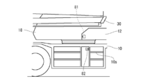
- the rough terrain crane 1 of the present embodiment has an emergency stop switch 81 arranged on the swivel 12 on the left side shown in FIG. 4 and an emergency stop switch 82 arranged near the center of the traveling body 10 in the vehicle longitudinal direction. And. Further, the rough terrain crane 1 of the present embodiment has an emergency stop switch 83 disposed near the center of the traveling body 10 in the vehicle front-rear direction on the right side shown in FIG. A stop switch 84.
- the mobile crane emergency stop device S of the present embodiment includes the traveling body 10, the swivel base 12, the actuators 53 to 57, the remote control means 40, and the emergency stop switches 81 to 84. Has been.
- These emergency stop switches 81 to 83 (84) are all push-button switches, and are formed to have a predetermined size so that they can be easily pushed with hands and feet even in an emergency. Further, the button portions of the emergency stop switches 81 to 83 (84) are colored red so as to stand out.
- the emergency stop switch 84 in the cab 18 may be a push button type mechanical switch or a virtual switch displayed in the display screen.
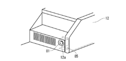
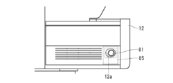
- the emergency stop switch 81 disposed on the swivel base 12 is disposed at the lower front end on the left side which is the opposite side of the cab 18 disposed on the right side of the swivel base 12. More specifically, the emergency stop switch 81 is located in the front of the long hole 12a inside the long hole 12a disposed on the outermost front surface of the lower part of the front end formed in a stepped shape on the left side of the swivel base 12. In this way, it is fixed to an L-shaped support 85 (switch fixing support).
- the emergency stop switch 81 disposed on the swivel base 12 takes into account the case where the emergency stop switches 82 and 83 disposed on the traveling body 10 to be described later are difficult to press due to the swivel base 12 turning. It is placed at a height that can be reached from workers on the ground.
- the emergency stop switch 81 is connected to the controller 70 by a communication cable (not shown).
- the “long hole” is defined as a hole having a horizontal dimension longer than a vertical dimension.
- the shape of the opening that communicates with the emergency stop switch 81 may be any shape that allows the toes to easily enter. Therefore, the shape of the opening is not limited to the long hole 12a, and may be an elliptical hole or a rectangular hole with rounded corners.
- the size is similar to that of the above and is slightly larger.
- the emergency stop switch 81 of a present Example is arrange
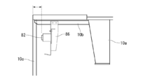
- the emergency stop switch 82 disposed on the left side surface of the traveling body 10 is disposed in the vicinity of the step 10 s disposed on the rear side of the left side surface of the traveling body 10. More specifically, the emergency stop switch 82 is installed immediately in front of the uppermost step 10 s of the traveling body 10. The emergency stop switch 82 is connected to the controller 70 by a communication cable (not shown).
- the emergency stop switch 82 is fixed to the traveling body 10 via an attachment 86 (an outrigger fixing support) attached to a bracket 10b extending laterally from the upper part of the frame 10a of the traveling body 10.
- the emergency stop switch 82 is disposed at a predetermined distance from the exterior surface.
- the emergency stop switch 82 is disposed at such a depth that it is difficult to be pushed by an unintended contact. Specifically, it can be arranged at a distance of about 10 cm to 20 cm from the surface of the exterior (including step 10 s).
- the emergency stop switch 83 disposed on the right side surface of the traveling body 10 is disposed in the vicinity of the step 10 s disposed near the front of the right side surface of the traveling body 10. More specifically, the emergency stop switch 83 is installed in the back between the uppermost step 10 s of the traveling body 10 and the deck.
- the emergency stop switch 83 is connected to the controller 70 by a communication cable (not shown).
- the emergency stop switch 83 is fixed to the traveling body 10 via an attachment 87 (switch fixing support) attached to a bracket 10b that extends laterally from the upper part of the frame 10a of the traveling body 10.
- the emergency stop switch 83 is arranged at a predetermined distance from the exterior surface. That is, the emergency stop switch 83 is disposed at a depth that is difficult to be pressed by an unintended contact. Specifically, it can be arranged at a distance of about 10 cm to 20 cm from the surface of the exterior (including step 10 s).
- an emergency stop switch 84 is also arranged in the cab 18.
- the emergency stop switch 84 is disposed at an appropriate location in the cab 18 so that the operation of the actuator can be stopped by being pressed by an operator in the cab 18 when two or more people are working.
- the emergency stop switch 84 is connected to the controller 70 by a communication cable (not shown).
- the emergency stop device S for a mobile crane includes a traveling body 10 having a traveling function, a swivel base 12 that is turnably mounted on the traveling body 10, and a working work.
- the emergency stop switches 81 to 84 are directly connected to the controller 70, the mobile crane emergency stop device S functions even if a malfunction occurs in the remote control means 40.
- the emergency stop switches 81 to 83 are pushed by an operator or an assistant in an emergency. It becomes easy.
- the swivel base 12 is provided with a boom 14 at the center of the left and right and a cab 18 on the left or right side, and the emergency stop switch 81 is located at the lower front end on the left or right side of the swivel 12.
- the jib attachment / detachment work is carried out by ascending on the traveling body 10, and the operator can press the emergency stop switch 81 with his / her foot even when both hands are occupied.
- the emergency stop switch 81 can be pushed with a foot even when the remote control means 40 is held with one hand and the wire rope 16 is held with the other hand.
- the emergency stop switch 81 of the swivel base 12 can also be reached from the ground, an operator who is in the vicinity and easily grasps the situation (a slinger, an assistant) detects the danger and presses the emergency stop switch 81. Can do.
- the emergency stop switches 82 and 83 are further arranged near the center of the traveling body 10 in the vehicle front-rear direction, so that even if there is an operator near the front of the vehicle, Even if there is an operator, the emergency stop switches 82 and 83 can be easily pushed.
- the emergency stop switches 82 and 83 are further arranged in the vicinity of the lifting step 10 s in the traveling body 10, even an operator who is on the ground (climber or assistant) can easily make an emergency.
- the stop switches 82 and 83 can be pressed.
- the operator who was working on the traveling body 10 can also press the emergency stop switches 82 and 83 while getting off the traveling body 10.
- the emergency stop switches 81 to 83 are arranged at a predetermined distance from the surface of the exterior, it is possible to prevent the operator from unintentionally pressing the emergency stop switches 81 to 83. .
- the step 10s functions as a protective fence for the emergency stop switches 81 to 83.
- the emergency stop switch 81 of the swivel base 12 is arranged inside the long hole 12a (or ellipse) that is large enough to fit the toe portion of the foot, making it difficult to accidentally press the emergency stop switch 81. . That is, if the long hole 12a having a size just enough to fit the toe portion is provided and the emergency stop switch 81 is disposed at the back of the long hole 12a, the possibility of accidental contact with the emergency stop switch 81 during work is suppressed. be able to.
- the remote operation means 40 As an example of “in use of the remote operation means 40”, the situation has been described in which the remote operation means 40 is turned on and remote control is possible. However, the present invention is not limited to this. Absent. Of course, the situation where the actuators 53 to 57 are actually operated by the remote control means 40 is also included.
- the condition that the jib attachment / detachment process mode is selected may be set, or the remote operation means is actually used in the jib attachment / detachment process mode. It is also possible to make a condition that a signal of 40 is being transmitted / received.
- the emergency stop switches 81 to 84 are connected to the controller 70 .
- the present invention is not limited to this, and the emergency stop switches 81 to 84 are engine controllers that control the engine 60. It may be connected to.
- the controller 70 is described as stopping the operation of the actuators 53 to 57 by stopping the engine 60.
- the present invention is not limited to this, and the actuator 53 is controlled by controlling the control valve 64. ⁇ 57 can also be stopped.
- the emergency stop switches 82 and 83 arranged on the traveling body 10 have been described in the vicinity of the elevating step 10s.
- the present invention is not limited to this.
- an emergency stop switch can be arranged by providing a hole in the exterior.
Landscapes
- Engineering & Computer Science (AREA)
- Mechanical Engineering (AREA)
- Automation & Control Theory (AREA)
- Control And Safety Of Cranes (AREA)
- Jib Cranes (AREA)
Abstract
遠隔操作手段に不具合が発生しても機能する緊急停止装置を提供する。移動式クレーンの緊急停止装置Sである。そして、緊急停止装置Sは、走行機能を有する走行体10と、走行体10に旋回自在に搭載される旋回台12と、作業用のアクチュエータ53~57と、アクチュエータ53~57を遠隔操作する遠隔操作手段40と、走行体10又は旋回台12に配置される緊急停止スイッチ81~84であって、遠隔操作手段40の使用中に、アクチュエータ53~57の動作を停止する緊急停止スイッチ81~84と、を備えている。
Description
本発明は、遠隔操作手段によって遠隔操作可能な移動式クレーンの緊急停止装置に関するものである。
従来から、移動式クレーンのアクチュエータを遠隔操作するための携帯型の遠隔操作手段が提案されている。例えば、車両搭載型クレーンでは比較的に操作入力数が少ないため、片手で操作できる小型の遠隔操作手段がすでに実現されている。遠隔操作手段を使用することで、フックの水平移動などの複合操作を容易に実施できるうえ、周囲の安全を確かめながら作業を実施できるという利点がある。
一方、遠隔操作手段は移動式クレーン本体と電波を使用して通信するように構成されているため、電波障害や混信への対応策を準備しておく必要がある。もちろん、混信の影響を受けにくい周波数領域を選択することは重要であるが、電波障害や故障の影響を受ける可能性はある。この他、遠隔操作手段を使用して比較的大型の移動式クレーンを操作する場合には、操作者には想定しえない危険(障害物接近等)が生じる可能性がある。このため、遠隔操作手段を使用する場合に、アクチュエータの動作を停止する緊急停止装置が提案されている。
例えば、特許文献1には、携帯型のペンダントスイッチ装置(有線型)自体に非常停止スイッチを設けて、非常停止スイッチが操作されるとポンプからエンジンの噴射ポンプへの燃料供給が停止される技術が開示されている。
しかしながら、特許文献1の非常停止スイッチは、ペンダントスイッチ装置(すなわち遠隔操作手段)自体に配置されるものであった。したがって、無線型の遠隔操作手段を使用する場合は、遠隔操作手段自体に電波障害や故障などの不具合が発生すると非常停止スイッチも機能しなくなる、という問題があった。
そこで、本発明は、遠隔操作手段に不具合が発生しても機能する緊急停止装置を提供することを目的としている。
前記目的を達成するために、本発明の移動式クレーンの緊急停止装置は、走行機能を有する走行体と、前記走行体に旋回自在に搭載される旋回台と、作業用のアクチュエータと、前記アクチュエータを遠隔操作する遠隔操作手段と、前記走行体又は前記旋回台に配置される緊急停止スイッチであって、前記遠隔操作手段の使用中に、前記アクチュエータの動作を停止する緊急停止スイッチと、を備えている。
このように、本発明の移動式クレーンの緊急停止装置は、走行体と、旋回台と、アクチュエータと、遠隔操作手段と、を備えており、さらに走行体又は旋回台に配置される緊急停止スイッチであって、遠隔操作手段の使用中に、アクチュエータの動作を停止する緊急停止スイッチと、を備えている。
以下、本発明の実施の形態について図面を参照して説明する。ただし、以下の実施の形態に記載されている構成要素は例示であり、本発明の技術範囲をそれらのみに限定する趣旨のものではない。
(構成)
まず、図1を用いて移動式クレーンの緊急停止装置Sを備える移動式クレーンとしてのラフテレーンクレーン1の全体構成について説明する。以下の実施例では、ラフテレーンクレーン1を例にして説明するが、これに限定されるものではなく、オールテレーンクレーンなどの移動式クレーンに広く本発明を適用できる。
まず、図1を用いて移動式クレーンの緊急停止装置Sを備える移動式クレーンとしてのラフテレーンクレーン1の全体構成について説明する。以下の実施例では、ラフテレーンクレーン1を例にして説明するが、これに限定されるものではなく、オールテレーンクレーンなどの移動式クレーンに広く本発明を適用できる。
(クレーンの全体構成)
本実施例のラフテレーンクレーン1は、図1に示すように、走行機能を有する車両の本体部分となる走行体10と、走行体10の四隅に設けられたアウトリガ11,・・・と、走行体10に水平旋回可能に取り付けられた旋回台12と、旋回台12に立設されたブラケット13に取り付けられたブーム14と、を備えている。後述するように、本実施例のラフテレーンクレーン1は、遠隔操作手段40を使用して遠隔操作可能となっている。さらに、ラフテレーンクレーン1には、遠隔操作手段40の使用中にアクチュエータの動作を停止する緊急停止スイッチ81、82(83)、84が配置されている。
本実施例のラフテレーンクレーン1は、図1に示すように、走行機能を有する車両の本体部分となる走行体10と、走行体10の四隅に設けられたアウトリガ11,・・・と、走行体10に水平旋回可能に取り付けられた旋回台12と、旋回台12に立設されたブラケット13に取り付けられたブーム14と、を備えている。後述するように、本実施例のラフテレーンクレーン1は、遠隔操作手段40を使用して遠隔操作可能となっている。さらに、ラフテレーンクレーン1には、遠隔操作手段40の使用中にアクチュエータの動作を停止する緊急停止スイッチ81、82(83)、84が配置されている。
旋回台12は、旋回用モータの動力を伝達されるピニオンギヤを有しており、このピニオンギヤが走行体10に設けた円形状のギヤに噛み合うことで旋回軸を中心に回動する。旋回台12は、前方右側に配置された運転室18と、後方中央に配置されたブラケット13と、後方下部に配置されたカウンタウェイト19と、を有している。
ブーム14は、基端ブーム141と中間ブーム142と先端ブーム143とによって入れ子式に構成されており、内部に配置された伸縮シリンダによって伸縮できるようになっている。先端ブーム143の最先端のブームヘッドにはシーブが配置され、シーブにワイヤロープ16が掛け回されてフックブロック17が吊下げられている。
最も外側の基端ブーム141は、付け根部がブラケット13に水平に設置された支持軸に回動自在に取り付けられており、支持軸を回転中心として上下に起伏できるようになっている。さらに、ブラケット13と基端ブーム141の下面との間には、起伏シリンダ15が架け渡されており、起伏シリンダ15を伸縮することでブーム14全体を起伏することができる。
さらに、本実施例のラフテレーンクレーン1では、基端ブーム141の側面に、ジブ30及びテンションロッド20、20が横抱姿勢にて格納されている。ジブ30及びテンションロッド20、20は、複数のピン(不図示)とサイドアップシリンダ31とを用いて、装着/格納される。
(制御系の構成)
次に、図2を用いて本実施例の遠隔操作手段40を含む制御系の構成について説明する。本実施例の制御系は、アクチュエータとして、旋回モータ53と、起伏シリンダ54と、伸縮シリンダ55と、メインウインチモータ56と、サブウインチモータ57と、を備えている。これらのアクチュエータは、後述するコントロールバルブ64によって制御される。
次に、図2を用いて本実施例の遠隔操作手段40を含む制御系の構成について説明する。本実施例の制御系は、アクチュエータとして、旋回モータ53と、起伏シリンダ54と、伸縮シリンダ55と、メインウインチモータ56と、サブウインチモータ57と、を備えている。これらのアクチュエータは、後述するコントロールバルブ64によって制御される。
そして、本実施例の制御系は、油圧回路として、エンジン60のトランスミッション61から動力を取り出すPTO62と、PTO62によって回転駆動され油タンク65からの作動油を加圧する油圧ポンプ63と、油圧ポンプ63から吐出される作動油の流れを制御するコントロールバルブ64と、を備えている。コントロールバルブ64は、各アクチュエータに対応するバルブ群から構成される。各バルブはコントローラ70によって制御される。
コントローラ70は、バス、演算装置、記憶装置などを有するコンピュータである。コントローラ70は、旋回レバー71、起伏レバー72、伸縮レバー73、メインウインチレバー74などからの操作信号を受信して、又は、通信部70aを介して遠隔操作手段40からの操作信号を受信して、各バルブの移動方向及び移動量を演算し、コントロールバルブ64に信号を送信することによってアクチュエータを制御する。
そして、本実施例のコントローラ70には、緊急停止スイッチ81~84が接続されている。コントローラ70は、遠隔操作手段40の使用中に(例えば遠隔操作手段40の電源がONになっているときに)、緊急停止スイッチ81~84からの信号を受信すると、エンジン60を停止する。さらに、コントローラ70は、緊急停止スイッチ81~84が押された後に、もう一度、緊急停止スイッチ81~84が押されると、エンジン60を始動するようになっている。
(遠隔操作手段の構成)
遠隔操作手段40は、図3に示すように、アクチュエータを操作するための操作面42と、操作面42の下方に延びて手で把持される把持部41と、を有する。遠隔操作手段40は通信部40a(図2参照)を有しており、レバースイッチS1~S4や設定ボタンF1~F3等を操作することでコントローラ70の通信部70aを介してコントローラ70に指示を出したり、コントローラ70から情報を取得したりする。把持部41の背面側には把持部41を握った状態で人差し指で操作されるトリガ(不図示)が配置されている。トリガは、選択手段によって選択されたアクチュエータを、選択された方向(正方向又は逆方向)に、操作量に応じた速度で駆動させる。
遠隔操作手段40は、図3に示すように、アクチュエータを操作するための操作面42と、操作面42の下方に延びて手で把持される把持部41と、を有する。遠隔操作手段40は通信部40a(図2参照)を有しており、レバースイッチS1~S4や設定ボタンF1~F3等を操作することでコントローラ70の通信部70aを介してコントローラ70に指示を出したり、コントローラ70から情報を取得したりする。把持部41の背面側には把持部41を握った状態で人差し指で操作されるトリガ(不図示)が配置されている。トリガは、選択手段によって選択されたアクチュエータを、選択された方向(正方向又は逆方向)に、操作量に応じた速度で駆動させる。
操作面42は、上部に配置される表示部43と;表示部43の右に配置される電源スイッチ44と;表示部の左下に配置されるモードボタン46と;モードボタン46の右に並んで配置される3つの設定ボタンF1、F2、F3と;モードボタン46及び設定ボタンF1、F2、F3に対応して下方に配置される4つの選択手段としての旋回レバースイッチS1、起伏レバースイッチS2、サブウインチレバースイッチS3、及びメインウインチレバースイッチS4と;を備えている。
表示部43は、液晶ディスプレイであり、モードボタン46を長押しすることで設定画面に切り替わり、モードボタン46に続いて設定ボタンF1、F2、F3を押すことによって、それぞれクレーンモード(敷板吊工程モード)、アウトリガ張出・格納工程モード、ジブ着脱工程モードに切り替わる。
(緊急停止スイッチの構成)
以下、図4~図10を用いて、緊急停止スイッチ81、82、83、84を備える緊急停止装置Sの構成について説明する。本実施例のラフテレーンクレーン1は、図4に示す左側面において、旋回台12に配置される緊急停止スイッチ81と、走行体10において車両前後方向の略中央近傍に配置される緊急停止スイッチ82と、を備えている。また、本実施例のラフテレーンクレーン1は、図5に示す右側面において、走行体10において車両前後方向の略中央近傍に配置される緊急停止スイッチ83と、運転室18内に配置される緊急停止スイッチ84と、を備えている。そして、本実施例の移動式クレーンの緊急停止装置Sは、上述した走行体10と、旋回台12と、アクチュエータ53~57と、遠隔操作手段40と、緊急停止スイッチ81~84と、によって構成されている。
以下、図4~図10を用いて、緊急停止スイッチ81、82、83、84を備える緊急停止装置Sの構成について説明する。本実施例のラフテレーンクレーン1は、図4に示す左側面において、旋回台12に配置される緊急停止スイッチ81と、走行体10において車両前後方向の略中央近傍に配置される緊急停止スイッチ82と、を備えている。また、本実施例のラフテレーンクレーン1は、図5に示す右側面において、走行体10において車両前後方向の略中央近傍に配置される緊急停止スイッチ83と、運転室18内に配置される緊急停止スイッチ84と、を備えている。そして、本実施例の移動式クレーンの緊急停止装置Sは、上述した走行体10と、旋回台12と、アクチュエータ53~57と、遠隔操作手段40と、緊急停止スイッチ81~84と、によって構成されている。
これらの緊急停止スイッチ81~83(84)は、いずれも押しボタン型のスイッチであり、緊急時にも手や足で押しやすいように所定の大きさに形成されている。さらに、緊急停止スイッチ81~83(84)のボタン部は、目立つように赤色に着色されている。なお、運転室18内の緊急停止スイッチ84は、押しボタン型等の機械的なスイッチであってもよいが、表示画面内に表示される仮想的なスイッチであってもよい。
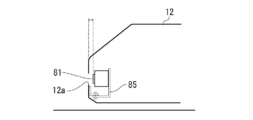
旋回台12に配置される緊急停止スイッチ81は、図4、図6に示すように、旋回台12において右側に配置された運転室18の反対側である左側の前端下部に配置されている。より具体的には、緊急停止スイッチ81は、旋回台12の左側の階段状に形成された前端下部の最前面の外寄りに配置された長孔12aの内部に、長孔12aの正面に位置するようにL字サポート85(スイッチ固定用サポート)に固定されている。さらに、旋回台12に配置される緊急停止スイッチ81は、旋回台12が旋回することで、後述する走行体10に配置される緊急停止スイッチ82、83を押しにくい姿勢となる場合を考慮して、地上にいる作業者から届く高さに配置されている。緊急停止スイッチ81は、通信ケーブル(不図示)によってコントローラ70と接続されている。
ここにおいて「長孔」とは縦辺の寸法よりも横辺の寸法が長く形成された孔と定義される。緊急停止スイッチ81に通ずる開口部の形状は、つま先が入りやすい形状であればよい。したがって、開口部の形状は長孔12aに限定されるものではなく、楕円形の孔であってもよいし、角が丸くなった長方形の孔などであってもよい。逆に、意図せずに誤って押される恐れを考慮すると、開口部は大きくし過ぎることは好ましくなく、安全靴や長靴などの大き目の靴のつま先が入る程度の大きさであり、かつ、つま先と相似形でひとまわり大きい寸法であることが好ましい。
そして、本実施例の緊急停止スイッチ81は、図8に示すように、外装の表面から所定の距離をおいて配置されている。すなわち、緊急停止スイッチ81は、長孔12aを通じて足の先端(つま先)を挿し入れて押せるものの、意図せずに誤って押されにくいような深さに配置されている。具体的には、外装の表面から例えば5cm~10cm程度の距離に配置することができる。
走行体10の左側面に配置される緊急停止スイッチ82は、図4に示すように、走行体10の左側面の後方寄りに設置されたステップ10sの近傍に配置されている。より具体的には、緊急停止スイッチ82は、走行体10の最上段のステップ10sのすぐ前方に設置されている。緊急停止スイッチ82は、通信ケーブル(不図示)によってコントローラ70と接続されている。
この緊急停止スイッチ82は、図9に示すように、走行体10のフレーム10a上部から横に延びるブラケット10bに取り付けられる取付材86(アウトリガ固定用サポート)を介して走行体10に固定される。そして、緊急停止スイッチ82は、外装の表面から所定の距離をおいて配置されている。すなわち、緊急停止スイッチ82は、意図しない接触によっては押されにくいような深さに配置されている。具体的には、外装(ステップ10sを含む)の表面から10cm~20cm程度の距離に配置することができる。
走行体10の右側面に配置される緊急停止スイッチ83は、図5に示すように、走行体10の右側面の前方寄りに設置されたステップ10sの近傍に配置されている。より具体的には、緊急停止スイッチ83は、走行体10の最上段のステップ10sとデッキとの間の奥に設置されている。緊急停止スイッチ83は、通信ケーブル(不図示)によってコントローラ70と接続されている。
この緊急停止スイッチ83は、図10に示すように、走行体10のフレーム10a上部から横に延びるブラケット10bに取り付けられる取付材87(スイッチ固定用サポート)を介して走行体10に固定される。そして、緊急停止スイッチ83は、外装の表面から所定の距離をおいて配置されている。すなわち、緊急停止スイッチ83は、意図しない接触によっては押されにくいような深さに配置されている。具体的には、外装(ステップ10sを含む)の表面から10cm~20cm程度の距離に配置することができる。
この他、運転室18内にも緊急停止スイッチ84が配置されている。この緊急停止スイッチ84は、運転室18内の適切な場所に配置されており、2人以上で作業する場合に運転室18内のオペレータが押すことでアクチュエータの動作を停止できるようになっている。緊急停止スイッチ84は、通信ケーブル(不図示)によってコントローラ70と接続されている。
(作用・効果)
次に、本実施例の移動式クレーンの緊急停止装置Sの作用・効果について説明する。
次に、本実施例の移動式クレーンの緊急停止装置Sの作用・効果について説明する。
(1)上述してきたように、本実施例の移動式クレーンの緊急停止装置Sは、走行機能を有する走行体10と、走行体10に旋回自在に搭載される旋回台12と、作業用のアクチュエータ53~57と、アクチュエータ53~57を遠隔操作する遠隔操作手段40と、走行体10又は旋回台12に配置される緊急停止スイッチ81~84であって、遠隔操作手段40の使用中に、アクチュエータ53~57の動作を停止する緊急停止スイッチ81~84と、を備えている。このような構成であれば、緊急停止スイッチ81~84はコントローラ70と直接に接続されるため、遠隔操作手段40に不具合が発生しても機能する移動式クレーンの緊急停止装置Sとなる。
さらに、走行体10又は旋回台12において運転室18の外に、押しボタン型の緊急停止スイッチ81~83を配置することによって、緊急時に作業者自身や補助者によって緊急停止スイッチ81~83を押しやすくなる。
(2)また、旋回台12には、左右中央にブーム14と左右いずれか一方側に運転室18とが配置され、緊急停止スイッチ81は、旋回台12において左右いずれか他方側の前端下部に配置されることで、走行体10上に昇ってジブ着脱作業などを実施しており、両手がふさがっている状態でも、作業者自らが足で緊急停止スイッチ81を押すことができる。例えば、一方の手で遠隔操作手段40を持ち、他方の手でワイヤロープ16を持っている状況でも、足で緊急停止スイッチ81を押すことができる。さらに、旋回台12の緊急停止スイッチ81には地上からも手が届くため、周囲にいて状況を把握しやすい作業者(玉掛け者、補助者)が危険を察知して緊急停止スイッチ81を押すことができる。
(3)さらに、緊急停止スイッチ82、83は、走行体10において車両前後方向の略中央近傍にさらに配置されることで、車両前方寄りの位置に作業者が居ても、車両後方寄りの位置に作業者が居ても、緊急停止スイッチ82、83を押しやすくなっている。
(4)また、緊急停止スイッチ82、83は、走行体10において昇降用ステップ10sの近傍にさらに配置されるため、地上にいる作業者(玉掛け者、補助者)であっても、容易に緊急停止スイッチ82、83を押すことができる。さらに、ステップ10sの近傍であれば、走行体10上で作業していた作業者自身が、走行体10から降りる途中で緊急停止スイッチ82、83を押すこともできる。
(5)また、緊急停止スイッチ81~83は、外装の表面から所定の距離をおいて配置されていることにより、作業者が意図せずに緊急停止スイッチ81~83を押してしまうことを防止できる。この場合、昇降用のステップ10sの奥に緊急停止スイッチ81~83を配置すれば、ステップ10sが緊急停止スイッチ81~83の防護柵としての機能を果たすようになる。
さらに、旋回台12の緊急停止スイッチ81は、足のつま先部分がちょうど入る程度の大きさの長孔12a(又は楕円)の内部に配置されることで、誤って緊急停止スイッチ81を押しにくくなる。つまり、つま先部分がちょうど入る程度の大きさの長孔12aを設けて、長孔12aの奥に緊急停止スイッチ81を配置すれば、作業中に誤って緊急停止スイッチ81と接触する可能性を抑えることができる。
以上、図面を参照して、本発明の実施例を詳述してきたが、具体的な構成は、この実施例に限らず、本発明の要旨を逸脱しない程度の設計的変更は、本発明に含まれる。
例えば、実施例では「遠隔操作手段40の使用中」の例として、遠隔操作手段40の電源がONにされて遠隔操作が可能となっている状況を説明したが、これに限定されるものではない。遠隔操作手段40によって実際にアクチュエータ53~57を操作している状況も、もちろん含まれる。
さらにいえば、「遠隔操作手段40の使用中」を限定する条件として、例えば、ジブ着脱工程モードが選択されていることを条件とすることもできるし、実際にジブ着脱工程モードにおいて遠隔操作手段40による信号を送受信中であることを条件とすることもできる。
また、実施例では、緊急停止スイッチ81~84がコントローラ70に接続されている場合について説明したが、これに限定されるものではなく、緊急停止スイッチ81~84は、エンジン60を制御するエンジンコントローラに接続されていてもよい。
さらに、実施例では、コントローラ70はエンジン60を停止することによってアクチュエータ53~57の動作を停止させるものとして説明したが、これに限定されるものではなく、コントロールバルブ64を制御することによってアクチュエータ53~57を停止することもできる。
また、実施例では、走行体10に配置される緊急停止スイッチ82、83が、昇降用ステップ10sの近傍に配置される場合について説明したが、これに限定されるものではない。例えば、外装に孔を設けて緊急停止スイッチを配置することもできる。
1:ラフテレーンクレーン; 10:走行体; 12:旋回台;
10s:ステップ; 10c:外装材;
20:テンションロッド; 30:ジブ;
40:遠隔操作手段;
53:旋回モータ; 54:起伏シリンダ; 55:伸縮シリンダ;
56:メインウインチモータ; 57:サブウインチモータ;
60:エンジン;
70:コントローラ;
81~84:緊急停止スイッチ
10s:ステップ; 10c:外装材;
20:テンションロッド; 30:ジブ;
40:遠隔操作手段;
53:旋回モータ; 54:起伏シリンダ; 55:伸縮シリンダ;
56:メインウインチモータ; 57:サブウインチモータ;
60:エンジン;
70:コントローラ;
81~84:緊急停止スイッチ
Claims (5)
- 移動式クレーンの緊急停止装置であって、
走行機能を有する走行体と、
前記走行体に旋回自在に搭載される旋回台と、
作業用のアクチュエータと、
前記アクチュエータを遠隔操作する遠隔操作手段と、
前記走行体又は前記旋回台に配置される緊急停止スイッチであって、前記遠隔操作手段の使用中に、前記アクチュエータの動作を停止する緊急停止スイッチと、を備える移動式クレーンの緊急停止装置。 - 前記旋回台には、左右中央にブームと左右いずれか一方側に運転室とが配置され、
前記緊急停止スイッチは、前記旋回台において左右いずれか他方側の前端下部に配置されることを特徴とする、請求項1に記載された移動式クレーンの緊急停止装置。 - 前記緊急停止スイッチは、前記走行体において車両前後方向の略中央近傍にさらに配置されることを特徴とする、請求項2に記載された移動式クレーンの緊急停止装置。
- 前記緊急停止スイッチは、前記走行体において昇降用ステップの近傍に配置されることを特徴とする、請求項3に記載された移動式クレーンの緊急停止装置。
- 前記緊急停止スイッチは、外装の表面から所定の距離をおいて配置されていることを特徴とする、請求項2乃至請求項4のいずれか一項に記載された移動式クレーンの緊急停止装置。
Applications Claiming Priority (2)
| Application Number | Priority Date | Filing Date | Title |
|---|---|---|---|
| JP2016082697A JP2017193384A (ja) | 2016-04-18 | 2016-04-18 | 移動式クレーンの緊急停止装置 |
| JP2016-082697 | 2016-04-18 |
Publications (1)
| Publication Number | Publication Date |
|---|---|
| WO2017183576A1 true WO2017183576A1 (ja) | 2017-10-26 |
Family
ID=60116025
Family Applications (1)
| Application Number | Title | Priority Date | Filing Date |
|---|---|---|---|
| PCT/JP2017/015293 Ceased WO2017183576A1 (ja) | 2016-04-18 | 2017-04-14 | 移動式クレーンの緊急停止装置 |
Country Status (2)
| Country | Link |
|---|---|
| JP (1) | JP2017193384A (ja) |
| WO (1) | WO2017183576A1 (ja) |
Families Citing this family (1)
| Publication number | Priority date | Publication date | Assignee | Title |
|---|---|---|---|---|
| JP2019163155A (ja) * | 2018-03-20 | 2019-09-26 | 株式会社タダノ | クレーン |
Citations (6)
| Publication number | Priority date | Publication date | Assignee | Title |
|---|---|---|---|---|
| US4508014A (en) * | 1982-06-08 | 1985-04-02 | U.S. Truck Cranes, Inc. | Remote control apparatus for a machine such as a crane |
| JPH056568U (ja) * | 1991-06-28 | 1993-01-29 | 富士通株式会社 | スイツチの誤操作防止構造 |
| JPH0515513Y2 (ja) * | 1987-06-18 | 1993-04-23 | ||
| JPH0940396A (ja) * | 1995-07-28 | 1997-02-10 | Aichi Corp | 作業車の非常停止装置 |
| JPH10265162A (ja) * | 1997-03-21 | 1998-10-06 | Hitachi Building Syst Co Ltd | 乗客コンベア |
| JP3030242B2 (ja) * | 1995-11-28 | 2000-04-10 | 新キャタピラー三菱株式会社 | 建設機械 |
-
2016
- 2016-04-18 JP JP2016082697A patent/JP2017193384A/ja active Pending
-
2017
- 2017-04-14 WO PCT/JP2017/015293 patent/WO2017183576A1/ja not_active Ceased
Patent Citations (6)
| Publication number | Priority date | Publication date | Assignee | Title |
|---|---|---|---|---|
| US4508014A (en) * | 1982-06-08 | 1985-04-02 | U.S. Truck Cranes, Inc. | Remote control apparatus for a machine such as a crane |
| JPH0515513Y2 (ja) * | 1987-06-18 | 1993-04-23 | ||
| JPH056568U (ja) * | 1991-06-28 | 1993-01-29 | 富士通株式会社 | スイツチの誤操作防止構造 |
| JPH0940396A (ja) * | 1995-07-28 | 1997-02-10 | Aichi Corp | 作業車の非常停止装置 |
| JP3030242B2 (ja) * | 1995-11-28 | 2000-04-10 | 新キャタピラー三菱株式会社 | 建設機械 |
| JPH10265162A (ja) * | 1997-03-21 | 1998-10-06 | Hitachi Building Syst Co Ltd | 乗客コンベア |
Also Published As
| Publication number | Publication date |
|---|---|
| JP2017193384A (ja) | 2017-10-26 |
Similar Documents
| Publication | Publication Date | Title |
|---|---|---|
| JP6306552B2 (ja) | 遠隔操作装置、及び案内システム | |
| JP6672681B2 (ja) | 遠隔操作装置 | |
| JP6231727B1 (ja) | 遠隔操作端末および移動式クレーンの遠隔操作システム | |
| EP3851409B1 (en) | Telehandler boom auxiliary control panel | |
| ES2768101T3 (es) | Sistema de elevación | |
| JP6231529B2 (ja) | 作業機 | |
| JP7256687B2 (ja) | 杭打機の安全システム | |
| CN102602809B (zh) | 工程机械的控制系统、方法和工程机械 | |
| WO2017183576A1 (ja) | 移動式クレーンの緊急停止装置 | |
| JP2010235225A (ja) | クレーンの操作装置及びクレーン | |
| SE535785C2 (sv) | Metod för nödräddning av personal vid schaktsänkning | |
| WO2015081772A1 (zh) | 一种起重机 | |
| JP5809082B2 (ja) | クレーンの携帯式遠隔操作装置 | |
| JP4528688B2 (ja) | 作業用車両 | |
| JP2007015774A (ja) | 高所作業車 | |
| JP7677056B2 (ja) | 携帯型の遠隔操作機 | |
| WO2012115568A1 (en) | Method for shaft sinking | |
| JP4280437B2 (ja) | ブームの作動制御装置 | |
| JP2015189534A (ja) | 高所作業車 | |
| JP2018100172A (ja) | クレーン | |
| JP2006321639A (ja) | 高所作業車 |
Legal Events
| Date | Code | Title | Description |
|---|---|---|---|
| NENP | Non-entry into the national phase |
Ref country code: DE |
|
| 121 | Ep: the epo has been informed by wipo that ep was designated in this application |
Ref document number: 17785914 Country of ref document: EP Kind code of ref document: A1 |
|
| 122 | Ep: pct application non-entry in european phase |
Ref document number: 17785914 Country of ref document: EP Kind code of ref document: A1 |