WO2017183444A1 - 整流用の冷媒流路を有する冷凍装置 - Google Patents
整流用の冷媒流路を有する冷凍装置 Download PDFInfo
- Publication number
- WO2017183444A1 WO2017183444A1 PCT/JP2017/014106 JP2017014106W WO2017183444A1 WO 2017183444 A1 WO2017183444 A1 WO 2017183444A1 JP 2017014106 W JP2017014106 W JP 2017014106W WO 2017183444 A1 WO2017183444 A1 WO 2017183444A1
- Authority
- WO
- WIPO (PCT)
- Prior art keywords
- pipe
- refrigerant
- axis
- flow
- refrigeration apparatus
- Prior art date
- Legal status (The legal status is an assumption and is not a legal conclusion. Google has not performed a legal analysis and makes no representation as to the accuracy of the status listed.)
- Ceased
Links
Images


Classifications
-
- F—MECHANICAL ENGINEERING; LIGHTING; HEATING; WEAPONS; BLASTING
- F15—FLUID-PRESSURE ACTUATORS; HYDRAULICS OR PNEUMATICS IN GENERAL
- F15D—FLUID DYNAMICS, i.e. METHODS OR MEANS FOR INFLUENCING THE FLOW OF GASES OR LIQUIDS
- F15D1/00—Influencing flow of fluids
- F15D1/02—Influencing flow of fluids in pipes or conduits
-
- F—MECHANICAL ENGINEERING; LIGHTING; HEATING; WEAPONS; BLASTING
- F16—ENGINEERING ELEMENTS AND UNITS; GENERAL MEASURES FOR PRODUCING AND MAINTAINING EFFECTIVE FUNCTIONING OF MACHINES OR INSTALLATIONS; THERMAL INSULATION IN GENERAL
- F16L—PIPES; JOINTS OR FITTINGS FOR PIPES; SUPPORTS FOR PIPES, CABLES OR PROTECTIVE TUBING; MEANS FOR THERMAL INSULATION IN GENERAL
- F16L55/00—Devices or appurtenances for use in, or in connection with, pipes or pipe systems
- F16L55/02—Energy absorbers; Noise absorbers
- F16L55/033—Noise absorbers
-
- F—MECHANICAL ENGINEERING; LIGHTING; HEATING; WEAPONS; BLASTING
- F25—REFRIGERATION OR COOLING; COMBINED HEATING AND REFRIGERATION SYSTEMS; HEAT PUMP SYSTEMS; MANUFACTURE OR STORAGE OF ICE; LIQUEFACTION SOLIDIFICATION OF GASES
- F25B—REFRIGERATION MACHINES, PLANTS OR SYSTEMS; COMBINED HEATING AND REFRIGERATION SYSTEMS; HEAT PUMP SYSTEMS
- F25B41/00—Fluid-circulation arrangements
Definitions
- the present invention relates to a refrigeration apparatus having a refrigerant flow path for rectification.
- the refrigerant circulates in parts such as the compressor, heat exchanger, and motor operated valve.
- the refrigerant proceeds as a drift in the bent pipe.
- the uneven flow is a fluid flow in which the distribution, density ratio, pressure, or mass flow ratio of the refrigerant is not uniform in the cross section of the pipe.
- drift is likely to occur.
- a shunt may be installed in the refrigerant pipe for introducing the refrigerant into the heat exchanger.
- the shunt disclosed in Patent Document 1 Japanese Patent Laid-Open No. 2002-130868
- An object of the present invention is to uniformize the refrigerant drift with a simple configuration and to suppress noise generated from the refrigerant piping of the refrigeration apparatus.
- the refrigeration apparatus includes a flow divider and a refrigerant flow path.
- the diverter diverts the refrigerant that has entered from the inflow port to a plurality of exit pipes.
- the refrigerant flow path is disposed on the upstream side of the refrigerant flow of the flow divider.
- the refrigerant flow path includes a first pipe, a second pipe, and a rectifying space forming member.
- the first pipe is connected to the inflow port.
- the second pipe is located upstream of the refrigerant flow with respect to the first pipe and includes a bent portion.
- the rectifying space forming member is disposed between the first pipe and the second pipe.
- the length of the first pipe is not less than 4 times and not more than 60 times the inner diameter of the first pipe.
- the flow passage area of the flow straightening space in the flow straightening space forming member is at least twice the flow passage area of the first pipe.
- the drift of the refrigerant is at least partially uniformized by the difference between the flow passage areas of the rectifying space and the first pipe.
- the simple structure of the rectifying space forming member can be easily provided in the piping of the refrigerant flow path. Therefore, the noise emitted from the refrigerant piping of the refrigeration apparatus can be suppressed.
- the refrigeration apparatus according to the second aspect of the present invention is the refrigeration apparatus according to the first aspect, wherein the volume V 0 of the rectifying space and the inner diameter D 1 of the first pipe are
- the volume of the rectifying space is equal to or greater than the volume of a cube having one side that is twice the inner diameter of the first pipe. Therefore, the rectifying space forming member is relatively small and easy to arrange in the refrigerant circuit.
- the refrigeration apparatus according to the third aspect of the present invention is the refrigeration apparatus according to the first aspect or the second aspect.
- the axes are not collinear.
- Refrigeration apparatus is the refrigeration apparatus according the first aspect in any one of the third aspect, when the direction of flow of refrigerant traveling from the rectifier space to the first pipe and the Z 1 axis Furthermore, the rectification space extends in both the X 1 axis and Y 1 axis directions perpendicular to the Z 1 axis.
- the rectification space is expanded three-dimensionally. Therefore, it is easy to equalize the refrigerant flow caused by the bent portion regardless of the direction of the bent portion of the second pipe.
- Refrigeration system is the refrigeration apparatus according to a fourth aspect, the flow direction of the refrigerant traveling in the rectifier space from the second pipe when the Z 2 axial, Z 1 axis and Z 2 axes Are not parallel.
- the inflow direction and the outflow direction of the refrigerant form a plane. Therefore, the drift of the refrigerant is made more uniform.
- the refrigeration apparatus is the refrigeration apparatus according to the fifth aspect, wherein the first pipe is connected to the outlet of the rectifying space forming member.
- Rectifying space includes a projection projecting in the direction of Z 2 axes beyond the position of the discharge port.
- the dead end portion contributes to uniform drift of the refrigerant.
- Refrigeration apparatus is the refrigeration apparatus according to a sixth aspect, the rectifying space occupies the starting end in the direction of Z 2 axes to the end. The outlet is closer to the end than the start.
- the first pipe is connected to the back side of the rectification space. Therefore, it is possible to optimize the effect that the flow straightening space makes the uneven flow uniform.
- the plurality of outlet pipes are three or more outlet pipes.
- noise generated from the refrigerant pipe can be suppressed.
- the rectifying space forming member is relatively small and can be easily arranged in the refrigerant circuit.
- the refrigeration apparatus increases the degree of freedom in designing the refrigerant flow path.
- the refrigeration apparatus According to the refrigeration apparatus according to the fourth aspect of the present invention, it is easy to equalize the refrigerant flow caused by the bent portion regardless of the direction of the bent portion of the second pipe.
- the refrigerant drift is made more uniform.
- the dead end part contributes to the uniform flow of the refrigerant.
- the effect of uniforming the drift in the rectifying space can be optimized.
- the refrigerant can be efficiently dispersed in the subsequent refrigerant circuit.
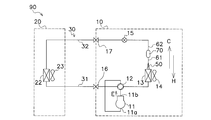
- FIG. 3 is a refrigerant circuit diagram of the refrigeration apparatus 90.
- FIG. It is a schematic diagram which shows the external appearance of the shunt 50 and the rectification
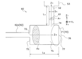
- 4 is a schematic diagram showing dimensions of a refrigerant flow path 60.
- FIG. It is a schematic diagram which shows the external appearance of the shunt 50 and the rectification
- FIG. 1 is a refrigerant circuit diagram of a refrigeration apparatus 90 according to an embodiment of the present invention.
- the refrigeration apparatus 90 is a heat pump device such as an air conditioner, a refrigerator, a water heater, or a floor heater.
- the refrigerant circuit of the refrigeration apparatus 90 includes a heat source unit 10, a utilization unit 20, and a refrigerant communication pipe 30.
- the heat source unit 10 is for generating cold or warm heat.
- the heat source unit 10 functions as a cold heat source when the refrigeration apparatus 90 performs a cold heat utilization operation, and functions as a heat source when the refrigeration apparatus 90 performs a warm heat utilization operation.
- the heat source unit 10 includes a compressor 11, a four-way switching valve 12, a heat source heat exchanger 13, a heat source fan 14, a flow divider 50, a rectifying refrigerant flow path 60, a heat source expansion valve 15, a gas closing valve 16, and a liquid closing valve. 17.
- (2-1-1) Compressor 11 The compressor 11 compresses the low-pressure gas refrigerant sucked from the suction port 11a, and discharges the high-pressure gas refrigerant from the discharge port 11b in the direction of arrow E in the drawing.
- the four-way switching valve 12 connects in the solid line in the figure when performing the cold heat utilization operation, and circulates the refrigerant in the direction of the arrow C in the refrigerant circuit.
- the four-way switching valve 12 performs a broken line connection when performing a heat utilization operation, and circulates the refrigerant in the direction of the arrow H in the refrigerant circuit.
- Heat source heat exchanger 13 exchanges heat between the refrigerant circulating in the refrigerant circuit and a heat exchange target such as air or water.
- the heat source heat exchanger 13 functions as a refrigerant condenser in the case of the cold utilization operation, and functions as a refrigerant evaporator in the case of the heat utilization operation.
- Heat source fan 14 The heat source fan 14 is provided when the refrigerant exchanges heat with air, and promotes heat exchange of the heat source heat exchanger 13.
- the flow divider 50 is for uniformly distributing the gas-liquid two-phase refrigerant flowing in the direction of the arrow H in FIG. 1 to each part of the heat source heat exchanger 13 in the operation using heat.
- the flow divider 50 includes a base 53 and four outlet pipes connected to the base 53, that is, a first outlet pipe 51a, a second outlet pipe 51b, a third outlet pipe 51c, and a fourth outlet.
- a pipe 51d is provided.
- the base 53 is a hollow member provided with an inflow port 52. The refrigerant flowing in from the inflow port 52 passes through the internal space of the base 53 and is distributed to the four outlet pipes.
- the X 1 axis, Y 1 axis, and Z 1 axis in the figure are axes that are orthogonal to each other.
- the Z 1 axis corresponds to the longitudinal direction of the first pipe 61 described later.
- the second outlet pipe 51b and the fourth outlet pipe 51d are spaced X 1 axial direction.
- the first outlet pipe 51a and the third outlet pipe 51c are spaced Y 1 axially.
- Rectification refrigerant flow path 60 The rectifying refrigerant flow path 60 is for eliminating the drift of the gas-liquid two-phase refrigerant flowing in the direction of arrow H in FIG.
- the term “uneven flow” as used herein refers to a fluid flow in which the distribution, density ratio, pressure, or mass flow rate ratio of the refrigerant is not uniform in the cross section of the pipe.
- the refrigerant flow path 60 improves the accuracy of uniformity in refrigerant distribution by the flow divider 50.
- the refrigerant flow path 60 includes a first pipe 61 connected to the flow divider 50, a rectifying space forming member 70 connected to the first pipe 61, and a second pipe 62 connected to the rectifying space forming member 70.
- the first pipe 61 is linear, and the second pipe 62 has at least one bent portion 63.
- One end of the first pipe 61 is connected to the inlet 52 of the flow divider 50, and the other end is connected to the outlet 74 of the rectifying space forming member 70.
- the second pipe 62 has a downstream section 62 a connected to the inlet 72 of the rectifying space forming member 70.
- Heat source expansion valve 15 is an electric valve whose opening degree can be adjusted, and has a function of depressurizing the refrigerant.
- Gas shut-off valve 16 is an openable / closable valve for switching connection or closing between the gas refrigerant communication pipe 31 and the refrigerant circuit in the heat source unit 10.
- the liquid closing valve 17 is an openable / closable valve that switches connection or closing between the liquid refrigerant communication pipe 32 and the refrigerant circuit in the heat source unit 10.
- the utilization heat exchanger 22 performs heat exchange between the refrigerant circulating in the refrigerant circuit and a heat exchange target such as air or water.
- the utilization heat exchanger 22 functions as a refrigerant evaporator in the cold utilization operation, and functions as a refrigerant condenser in the heat utilization operation.
- (2-2-2) Fan 23 used The use fan 23 is provided when the refrigerant exchanges heat with air, and promotes heat exchange of the use heat exchanger 22.
- Refrigerant communication pipe 30 moves the refrigerant between the heat source unit 10 and the utilization unit 20.
- Gas refrigerant communication pipe 31 moves the gas refrigerant from the heat source unit 10 to the utilization unit 20 or in the opposite direction.
- the gas-liquid two-phase refrigerant enters the utilization unit 20 through the opened liquid closing valve 17 and the liquid refrigerant communication pipe 32 in this order.
- the gas-liquid two-phase refrigerant reaches the utilization heat exchanger 22, where it provides cold heat to the user in the process of evaporating into a low-pressure gas refrigerant.
- the low-pressure gas refrigerant enters the heat source unit 10 through the gas refrigerant communication pipe 31 and the opened gas closing valve 16 in this order.
- the low-pressure gas refrigerant is sucked into the compressor 11 after passing through the four-way switching valve 12.
- the four-way switching valve 12 of the heat source unit 10 performs the connection indicated by the broken line.
- the refrigerant circulates in the refrigerant circuit in the direction of arrow H.
- the compressor 11 discharges the high-pressure gas refrigerant in the direction of arrow E.
- the high-pressure gas refrigerant passes through the four-way switching valve 12 and then enters the utilization unit 20 through the opened gas closing valve 16 and the gas refrigerant communication pipe 31 in order.
- the high-pressure gas refrigerant reaches the use heat exchanger 22 and provides heat to the user in the process of condensing there to become a high-pressure liquid refrigerant.
- the high-pressure liquid refrigerant enters the heat source unit 10 through the liquid refrigerant communication pipe 32 and the opened liquid closing valve 17 in order.
- the high-pressure liquid refrigerant reaches the heat source expansion valve 15, where it is decompressed and becomes a gas-liquid two-phase refrigerant.
- the gas-liquid two-phase refrigerant sequentially passes through the rectifying refrigerant flow path 60 and the flow divider 50, reaches the heat source heat exchanger 13, and evaporates there to become a low-pressure gas refrigerant.
- the low-pressure gas refrigerant is sucked into the compressor 11 through the four-way switching valve 12.
- FIG. 3 schematically shows the refrigerant flow path 60.
- the second pipe 62 is located on the upstream side of the refrigerant, and the flow divider 50 is located on the downstream side.
- the refrigerant flowing through the downstream section 62 a of the second pipe 62 enters the rectifying space 71 of the rectifying space forming member 70 from the inlet 72 and exits from the outlet 74 to the first pipe 61.
- the Z 1 axis is the refrigerant outflow direction from the rectifying space 71
- the Z 2 axis is the refrigerant inflow direction into the rectifying space 71.
- the Z 1 axis corresponds to the longitudinal direction of the first pipe 61.
- the Z 2 axis corresponds to the longitudinal direction of the downstream section 62 a of the second pipe 62.
- the refrigerant flowing through the downstream section 62a is uneven due to the bent portion 63 and other causes of the second pipe 62.
- the rectifying space 71 extends from the start end 75 to the end end 77 in the Z 2 axis direction over the dimension L 0 and has a flow path area A 0 .
- the flow path area A 0 is a cross-sectional area of the rectifying space 71 when cut along a plane perpendicular to the Z 2 axis direction.
- the rectifying space 71 extends in both the X 1 axis and Y 1 axis directions, and has a volume V 0 .
- the distance from the start end 75 to the discharge port 74 is longer than the distance from the discharge port 74 to the end 77.
- the discharge port 74 is provided closer to the end 77 than the start 75.
- the discharge port 74 is located at a position closer to the start end 75 by a predetermined dimension than the position of the terminal end 77, thereby forming a protrusion 78 protruding in the Z 2 axis direction in the rectifying space 71.
- the first pipe 61 extends from the outlet 74 of the rectifying space forming member 70 to the inlet 52 of the flow distributor 50.
- the Z 1 axis typically intersects the Z 2 axis.
- the angle formed by the Z 1 axis and the Z 2 axis is preferably 90 °, but may be other than 0 °.
- a configuration in which the Z 1 axis and the Z 2 axis are parallel and the axes of the first pipe 61 and the second pipe 62 are off the same straight line is also possible.
- the Z 2 axis typically coincides with the aforementioned Y 1 axis, but does not necessarily have to coincide.
- the refrigerant typically changes its traveling direction in the rectifying space 71 and enters the first pipe 61.
- the first pipe 61 has a length L 1, the inner diameter D 1, and a flow area A 1 of Z 1 axial direction.
- the flow path area A 1 is a cross-sectional area of the internal space of the first pipe 61 when cut along a plane perpendicular to the Z 1 axis direction.
- a 1 ⁇ (D 1/ 2) 2.
- the length L 1 is not less than 4 times and not more than 60 times the inner diameter D 1 .
- the flow passage area A 0 of the rectifying space 71 is at least twice the flow passage area A 1 of the first pipe 61.
- the relationship is established.
- the refrigerant travels in the first pipe 61 in the Z 1 axis direction and enters the flow divider 50.
- the length L 1 of the first pipe 61 is not more than 60 times more than four times the inner diameter D 1, the flow path area A 0 of the rectifying space 71 is first at least twice the flow area A 1 of the pipe 61.
- the drift of the refrigerant is at least partially uniformized by the difference in flow path area between the rectifying space 71 and the first pipe 61.
- the length of the first pipe 61 By the length of the first pipe 61 to more than 4 times the internal diameter D 1, stabilization of the refrigerant flow through the first pipe 61 can be reduced. By the length of the first pipe 61 to less than 60 times the inner diameter D 1, it can be the size of the refrigeration system 90 to realistic.
- the simple structure of the rectifying space forming member 70 can be easily provided in the piping of the refrigerant flow path. Therefore, noise generated from the refrigerant pipe of the refrigeration apparatus 90 can be easily suppressed.
- the above-described mathematical relationship is established between the volume V 0 of the rectifying space 71 and the inner diameter D 1 of the first pipe 61.
- the volume V 0 of the rectifying space 71 is not less than the volume of a cube having one side that is twice the inner diameter D 1 of the first pipe 61. Therefore, the rectifying space forming member 70 is relatively small and can be easily arranged in the refrigerant circuit.
- the Z 1 axis typically intersects the Z 2 axis.
- the axis of the first pipe 61 and the second pipe 62 is off the same straight line. Accordingly, since the first pipe 61 and the second pipe 62 are not aligned, the degree of freedom in designing the refrigerant flow path is increased.
- the rectifying space 71 extends in both the X 1 axis and the Y 1 axis. Therefore, it is easy to equalize the refrigerant flow caused by the bent portion 63 regardless of the direction of the bent portion 63 of the second pipe 62.
- the Z 1 axis typically intersects the Z 2 axis. Therefore, since the inflow direction and the outflow direction of the refrigerant form a plane, the drift of the refrigerant is made more uniform.
- the rectifying space 71 includes a projecting portion 78, that is, a dead end portion that extends in the Z 2 axis direction from the discharge port 74. Therefore, this dead end portion contributes to uniform drift of the refrigerant.
- the discharge port 74 is provided in a place closer to the end 77 than the start 75. Therefore, since the 1st piping 61 is connected to the back
- FIG. 4 shows a configuration according to Modification B of the above-described embodiment of the present invention.
- Modification B is different from the above-described embodiment in that a dead end piping part 79 is further provided at the position of the protruding part 78 of the rectifying space forming member 70.
- the axis of the dead end piping part 79 is on the same straight line as the downstream section 62 a of the second pipe 62 and the axis.
- the dead end piping portion 79 typically has the same inner diameter as the downstream section 62a.
Landscapes
- Engineering & Computer Science (AREA)
- General Engineering & Computer Science (AREA)
- Mechanical Engineering (AREA)
- Physics & Mathematics (AREA)
- Thermal Sciences (AREA)
- Fluid Mechanics (AREA)
- Air-Conditioning For Vehicles (AREA)
- Other Air-Conditioning Systems (AREA)
Abstract
冷凍装置(90)は、分流器(50)と、冷媒流路(60)と、を備える。分流器(50)は、流入口(52)から入った冷媒を複数の出口配管(51a~51d)に分流する。冷媒流路(60)は、分流器(50)の冷媒流れ上流側に配置される。冷媒流路(60)は、第1配管(61)と、第2配管(62)と、整流空間形成部材(70)と、を有する。第1配管(61)は、流入口(52)に接続される。第2配管(62)は、第1配管(61)よりも冷媒流れ上流側に位置するとともに曲げ部(63)を含む。整流空間形成部材(70)は、第1配管(61)と第2配管(62)との間に配置される。第1配管(61)の長さ(L1)は、第1配管(61)の内径(D1)の4倍以上60倍以下である。整流空間形成部材(70)の中の整流空間(71)の流路面積(A0)は、第1配管(61)の流路面積(A1)の2倍以上である。
Description
本発明は、整流用の冷媒流路を有する冷凍装置に関する。
冷凍装置の冷媒回路では、圧縮機、熱交換器、電動弁などの部品に冷媒が循環する。冷媒は、曲がった配管の中を偏流として進行する。偏流とは、配管の断面において冷媒の分布、密度比、圧力、または質量流量比が不均一である流体流のことである。とりわけ、冷媒が気液二相状態にある場合には、偏流が発生しやすい。熱交換器へ冷媒を導入する冷媒配管には分流器が設置される場合がある。特許文献1(特開2002-130868号公報)が開示する分流器は、冷媒が引き起こす騒音を低減する機能を持つ。この機能は、冷媒の偏流を均一化するための絞り部材によって達成されている。
絞り部材などの新規部品の追加は、分流器の部品点数を増加させ、コストを上昇させる。
本発明の課題は、簡素な構成によって冷媒の偏流を均一化し、冷凍装置の冷媒配管から発される騒音を抑制することである。
本発明の第1観点に係る冷凍装置は、分流器と、冷媒流路と、を備える。分流器は、流入口から入った冷媒を複数の出口配管に分流する。冷媒流路は、分流器の冷媒流れ上流側に配置される。冷媒流路は、第1配管と、第2配管と、整流空間形成部材と、を有する。第1配管は、流入口に接続される。第2配管は、第1配管よりも冷媒流れ上流側に位置するとともに曲げ部を含む。整流空間形成部材は、第1配管と第2配管との間に配置される。第1配管の長さは、第1配管の内径の4倍以上60倍以下である。整流空間形成部材の中の整流空間の流路面積は、第1配管の流路面積の2倍以上である。
この構成によれば、整流空間と第1配管の流路面積の差によって冷媒の偏流が少なくとも部分的に均一化される。整流空間形成部材という単純な構造は冷媒流路の配管に容易に設けることができる。したがって、冷凍装置の冷媒配管から発される騒音を抑制することができる。
本発明の第2観点に係る冷凍装置は、第1観点に係る冷凍装置において、整流空間の体積V0と第1配管の内径D1が、

この構成によれば、整流空間の体積は、第1配管の内径の2倍を1辺とする立方体の体積以上である。したがって、整流空間形成部材は比較的小さく、冷媒回路への配置が容易である。
本発明の第3観点に係る冷凍装置は、第1観点または第2観点に係る冷凍装置において、整流空間に接続する箇所における第1配管の軸線、および整流空間に接続する箇所における第2配管の軸線が同一直線上にない。
この構成によれば、第1配管と第2配管が整列しない。したがって、冷媒流路の設計に自由度が増す。
本発明の第4観点に係る冷凍装置は、第1観点から第3観点のいずれか1つに係る冷凍装置において、整流空間から第1配管へ進行する冷媒の流出方向をZ1軸としたときに、整流空間がZ1軸に垂直なX1軸およびY1軸のいずれの方向にも拡がる。
この構成によれば、整流空間は3次元的に広がる。したがって、第2配管が有する曲がり部がいかなる方向にあっても、曲がり部に起因する冷媒の偏流を均一化しやすい。
本発明の第5観点に係る冷凍装置は、第4観点に係る冷凍装置において、第2配管から整流空間へ進行する冷媒の流入方向をZ2軸としたときに、Z1軸とZ2軸は平行でない。
この構成によれば、冷媒の流入方向と流出方向が平面をつくる。したがって、冷媒の偏流がより均一化される。
本発明の第6観点に係る冷凍装置は、第5観点に係る冷凍装置において、第1配管が整流空間形成部材の排出口に接続される。整流空間は、排出口の位置を越えてZ2軸の方向に突出する突出部を含む。
この構成によれば、整流空間において、排出口よりもZ2軸方向に広がる部分が行き止まり部分を形成する。したがって、行き止まり部分が冷媒の偏流の均一化に寄与する。
本発明の第7観点に係る冷凍装置は、第6観点に係る冷凍装置において、整流空間がZ2軸の方向に始端から終端までを占める。排出口は始端より終端に近い。
この構成によれば、第1配管は整流空間の奥側に接続される。したがって、整流空間が偏流を均一する効果を最適化できる。
本発明の第8観点に係る冷凍装置は、第1観点から第7観点のいずれか1つに係る冷凍装置において、複数の出口配管は3以上の出口配管である。
この構成によれば、均一化された3つ以上の冷媒流が分流器から排出される。したがって、後段の冷媒回路で効率よく冷媒を分散できる。
本発明の第1観点に係る冷凍装置によれば、冷媒配管から発される騒音を抑制することができる。
本発明の第2観点に係る冷凍装置によれば、整流空間形成部材は比較的小さく、冷媒回路への配置が容易である。
本発明の第3観点に係る冷凍装置によれば、冷媒流路の設計に自由度が増す。
本発明の第4観点に係る冷凍装置によれば、第2配管が有する曲がり部がいかなる方向にあっても、曲がり部に起因する冷媒の偏流を均一化しやすい。
本発明の第5観点に係る冷凍装置によれば、冷媒の偏流がより均一化される。
本発明の第6観点に係る冷凍装置によれば、行き止まり部分が冷媒の偏流の均一化に寄与する。
本発明の第7観点に係る冷凍装置によれば、整流空間が偏流を均一する効果を最適化できる。
本発明の第8観点に係る冷凍装置によれば、後段の冷媒回路で効率よく冷媒を分散できる。
以下、本発明に係る空気調和装置の実施形態について、図面を用いて説明する。なお、本発明にかかる空気調和装置の具体的な構成は、下記の実施形態に限られるものではなく、発明の要旨を逸脱しない範囲で適宜変更可能である。
(1)全体構成
図1は、本発明の一実施形態に係る冷凍装置90の冷媒回路図である。冷凍装置90は、例えば空気調和機、冷蔵庫、給湯機、床暖房装置などのヒートポンプ装置である。冷凍装置90の冷媒回路は、熱源ユニット10、利用ユニット20、冷媒連絡配管30を備える。
図1は、本発明の一実施形態に係る冷凍装置90の冷媒回路図である。冷凍装置90は、例えば空気調和機、冷蔵庫、給湯機、床暖房装置などのヒートポンプ装置である。冷凍装置90の冷媒回路は、熱源ユニット10、利用ユニット20、冷媒連絡配管30を備える。
(2)詳細構成
(2-1)熱源ユニット10
熱源ユニット10は、冷熱または温熱を発生させるためのものである。熱源ユニット10は、冷凍装置90が冷熱利用運転を行う際には冷熱源として機能し、冷凍装置90が温熱利用運転を行う際には温熱源として機能する。熱源ユニット10は、圧縮機11、四路切替弁12、熱源熱交換器13、熱源ファン14、分流器50、整流用の冷媒流路60、熱源膨張弁15、ガス閉鎖弁16、液閉鎖弁17を有する。
(2-1)熱源ユニット10
熱源ユニット10は、冷熱または温熱を発生させるためのものである。熱源ユニット10は、冷凍装置90が冷熱利用運転を行う際には冷熱源として機能し、冷凍装置90が温熱利用運転を行う際には温熱源として機能する。熱源ユニット10は、圧縮機11、四路切替弁12、熱源熱交換器13、熱源ファン14、分流器50、整流用の冷媒流路60、熱源膨張弁15、ガス閉鎖弁16、液閉鎖弁17を有する。
(2-1-1)圧縮機11
圧縮機11は、吸入ポート11aから吸入した低圧ガス冷媒を圧縮して、吐出ポート11bから高圧ガス冷媒を図中の矢印Eの方向へ吐出する。
圧縮機11は、吸入ポート11aから吸入した低圧ガス冷媒を圧縮して、吐出ポート11bから高圧ガス冷媒を図中の矢印Eの方向へ吐出する。
(2-1-2)四路切替弁12
四路切替弁12は、冷熱利用運転を行う場合には図中の実線の接続を行い、冷媒回路内で冷媒を矢印Cの方向に循環させる。四路切替弁12は、温熱利用運転を行う場合には破線の接続を行い、冷媒回路内で冷媒を矢印Hの方向に循環させる。
四路切替弁12は、冷熱利用運転を行う場合には図中の実線の接続を行い、冷媒回路内で冷媒を矢印Cの方向に循環させる。四路切替弁12は、温熱利用運転を行う場合には破線の接続を行い、冷媒回路内で冷媒を矢印Hの方向に循環させる。
(2-1-3)熱源熱交換器13
熱源熱交換器13は、冷媒回路を循環する冷媒と、空気または水などの熱交換対象との間で熱交換を行わせる。熱源熱交換器13は、冷熱利用運転の場合には冷媒の凝縮器として機能し、温熱利用運転の場合には冷媒の蒸発器として機能する。
熱源熱交換器13は、冷媒回路を循環する冷媒と、空気または水などの熱交換対象との間で熱交換を行わせる。熱源熱交換器13は、冷熱利用運転の場合には冷媒の凝縮器として機能し、温熱利用運転の場合には冷媒の蒸発器として機能する。
(2-1-4)熱源ファン14
熱源ファン14は、冷媒が空気と熱交換を行う場合に設けられ、熱源熱交換器13の熱交換を促進する。
熱源ファン14は、冷媒が空気と熱交換を行う場合に設けられ、熱源熱交換器13の熱交換を促進する。
(2-1-5)分流器50
分流器50は、温熱利用運転において、図1の矢印Hの方向に流れる気液二相冷媒を、熱源熱交換器13の各部に均一に分配するためのものである。
分流器50は、温熱利用運転において、図1の矢印Hの方向に流れる気液二相冷媒を、熱源熱交換器13の各部に均一に分配するためのものである。
図2に示すように、分流器50は、基部53と、基部53に接続された4本の出口配管、すなわち第1出口配管51a、第2出口配管51b、第3出口配管51c、第4出口配管51dを有する。基部53は流入口52を設けられた中空の部材である。流入口52から流入した冷媒は、基部53の内部空間を経て、4本の出口配管に分配される。
図中のX1軸、Y1軸、Z1軸は相互に直行する軸である。Z1軸は後述する第1配管61の長手方向に相当する。第2出口配管51bと第4出口配管51dはX1軸方向に離間している。第1出口配管51aと第3出口配管51cはY1軸方向に離間している。
(2-1-6)整流用の冷媒流路60
整流用の冷媒流路60は、温熱利用運転において、図1の矢印Hの方向に流れる気液二相冷媒の偏流を解消するためのものである。ここでいう「偏流」とは、配管の断面において冷媒の分布、密度比、圧力、または質量流量比が不均一である流体流のことである。冷媒流路60は、分流器50による冷媒の分配における均一さの精度を向上させる。冷媒流路60は、分流器50に接続される第1配管61、第1配管61に接続される整流空間形成部材70、および、整流空間形成部材70に接続される第2配管62を有する。
整流用の冷媒流路60は、温熱利用運転において、図1の矢印Hの方向に流れる気液二相冷媒の偏流を解消するためのものである。ここでいう「偏流」とは、配管の断面において冷媒の分布、密度比、圧力、または質量流量比が不均一である流体流のことである。冷媒流路60は、分流器50による冷媒の分配における均一さの精度を向上させる。冷媒流路60は、分流器50に接続される第1配管61、第1配管61に接続される整流空間形成部材70、および、整流空間形成部材70に接続される第2配管62を有する。
図2に示すように、第1配管61は直線状であり、第2配管62は少なくとも1つの曲げ部63を有する。第1配管61は、その一端が分流器50の流入口52に接続され、他端が整流空間形成部材70の排出口74に接続されている。第2配管62は、その下流区間62aが整流空間形成部材70の流入口72に接続されている。
(2-1-7)熱源膨張弁15
図1に戻り、熱源膨張弁15は開度調整可能な電動弁であり、冷媒を減圧させる機能を有する。
図1に戻り、熱源膨張弁15は開度調整可能な電動弁であり、冷媒を減圧させる機能を有する。
(2-1-8)ガス閉鎖弁16
ガス閉鎖弁16は、ガス冷媒連絡配管31と熱源ユニット10内の冷媒回路との接続または閉鎖を切り替える開閉可能な弁である。
ガス閉鎖弁16は、ガス冷媒連絡配管31と熱源ユニット10内の冷媒回路との接続または閉鎖を切り替える開閉可能な弁である。
(2-1-9)液閉鎖弁17
液閉鎖弁17は、液冷媒連絡配管32と熱源ユニット10内の冷媒回路との接続または閉鎖を切り替える開閉可能な弁である。
液閉鎖弁17は、液冷媒連絡配管32と熱源ユニット10内の冷媒回路との接続または閉鎖を切り替える開閉可能な弁である。
(2-2)利用ユニット20
(2-2-1)利用熱交換器22
利用熱交換器22は、冷媒回路を循環する冷媒と、空気または水などの熱交換対象との間で熱交換を行わせる。利用熱交換器22は、冷熱利用運転の場合には冷媒の蒸発器として機能し、温熱利用運転の場合には冷媒の凝縮器として機能する。
(2-2-1)利用熱交換器22
利用熱交換器22は、冷媒回路を循環する冷媒と、空気または水などの熱交換対象との間で熱交換を行わせる。利用熱交換器22は、冷熱利用運転の場合には冷媒の蒸発器として機能し、温熱利用運転の場合には冷媒の凝縮器として機能する。
(2-2-2)利用ファン23
利用ファン23は、冷媒が空気と熱交換を行う場合に設けられ、利用熱交換器22の熱交換を促進する。
利用ファン23は、冷媒が空気と熱交換を行う場合に設けられ、利用熱交換器22の熱交換を促進する。
(2-3)冷媒連絡配管30
冷媒連絡配管30は、熱源ユニット10と利用ユニット20の間で冷媒を移動させる。
冷媒連絡配管30は、熱源ユニット10と利用ユニット20の間で冷媒を移動させる。
(2-3-1)ガス冷媒連絡配管31
ガス冷媒連絡配管31は、ガス冷媒を熱源ユニット10から利用ユニット20へ、またはその逆方向に移動させる。
ガス冷媒連絡配管31は、ガス冷媒を熱源ユニット10から利用ユニット20へ、またはその逆方向に移動させる。
(2-3-2)液冷媒連絡配管32
ガス冷媒連絡配管31は、液冷媒または気液二相冷媒を熱源ユニット10から利用ユニット20へ、またはその逆方向に移動させる。
ガス冷媒連絡配管31は、液冷媒または気液二相冷媒を熱源ユニット10から利用ユニット20へ、またはその逆方向に移動させる。
(3)基本動作
(3-1)冷熱利用運転
図1において、熱源ユニット10の四路切替弁12は実線で示される接続を行う。冷媒は、冷媒回路を矢印Cの方向に循環する。圧縮機11は高圧ガス冷媒を矢印Eの方向に吐する。高圧ガス冷媒はその後、四路切替弁12を経て熱源熱交換器13へ到達し、そこで凝縮して高圧液冷媒になる。高圧液冷媒は、分流器50および整流用の冷媒流路60を順に経て、熱源膨張弁15へ到達し、そこで減圧されて気液二相冷媒になる。気液二相冷媒は、開放された液閉鎖弁17および液冷媒連絡配管32を順に経て、利用ユニット20に入る。気液二相冷媒は利用熱交換器22に到達し、そこで蒸発して低圧ガス冷媒になる過程で利用者に冷熱を提供する。低圧ガス冷媒は、ガス冷媒連絡配管31および開放されたガス閉鎖弁16を順に経て、熱源ユニット10へ入る。低圧ガス冷媒は四路切替弁12を通過した後、圧縮機11に吸入される。
(3-1)冷熱利用運転
図1において、熱源ユニット10の四路切替弁12は実線で示される接続を行う。冷媒は、冷媒回路を矢印Cの方向に循環する。圧縮機11は高圧ガス冷媒を矢印Eの方向に吐する。高圧ガス冷媒はその後、四路切替弁12を経て熱源熱交換器13へ到達し、そこで凝縮して高圧液冷媒になる。高圧液冷媒は、分流器50および整流用の冷媒流路60を順に経て、熱源膨張弁15へ到達し、そこで減圧されて気液二相冷媒になる。気液二相冷媒は、開放された液閉鎖弁17および液冷媒連絡配管32を順に経て、利用ユニット20に入る。気液二相冷媒は利用熱交換器22に到達し、そこで蒸発して低圧ガス冷媒になる過程で利用者に冷熱を提供する。低圧ガス冷媒は、ガス冷媒連絡配管31および開放されたガス閉鎖弁16を順に経て、熱源ユニット10へ入る。低圧ガス冷媒は四路切替弁12を通過した後、圧縮機11に吸入される。
(3-2)温熱利用運転
図1において、熱源ユニット10の四路切替弁12は破線で示される接続を行う。冷媒は、冷媒回路を矢印Hの方向に循環する。圧縮機11は高圧ガス冷媒を矢印Eの方向に吐する。高圧ガス冷媒はその後、四路切替弁12を通過した後、開放されたガス閉鎖弁16およびガス冷媒連絡配管31を順に経て利用ユニット20に入る。高圧ガス冷媒は、利用熱交換器22に到達し、そこで凝縮して高圧液冷媒になる過程で利用者に温熱を提供する。高圧液冷媒は、液冷媒連絡配管32および開放された液閉鎖弁17を順に経て、熱源ユニット10へ入る。高圧液冷媒は、熱源膨張弁15へ到達し、そこで減圧されて気液二相冷媒になる。気液二相冷媒は、整流用の冷媒流路60および分流器50を順に経て、熱源熱交換器13へ到達し、そこで蒸発して低圧ガス冷媒になる。低圧ガス冷媒は、四路切替弁12を経て圧縮機11に吸入される。
図1において、熱源ユニット10の四路切替弁12は破線で示される接続を行う。冷媒は、冷媒回路を矢印Hの方向に循環する。圧縮機11は高圧ガス冷媒を矢印Eの方向に吐する。高圧ガス冷媒はその後、四路切替弁12を通過した後、開放されたガス閉鎖弁16およびガス冷媒連絡配管31を順に経て利用ユニット20に入る。高圧ガス冷媒は、利用熱交換器22に到達し、そこで凝縮して高圧液冷媒になる過程で利用者に温熱を提供する。高圧液冷媒は、液冷媒連絡配管32および開放された液閉鎖弁17を順に経て、熱源ユニット10へ入る。高圧液冷媒は、熱源膨張弁15へ到達し、そこで減圧されて気液二相冷媒になる。気液二相冷媒は、整流用の冷媒流路60および分流器50を順に経て、熱源熱交換器13へ到達し、そこで蒸発して低圧ガス冷媒になる。低圧ガス冷媒は、四路切替弁12を経て圧縮機11に吸入される。
(4)詳細構造
図3は冷媒流路60を模式的に示している。温熱利用運転において、冷媒の上流側に位置するのは第2配管62であり、下流側に位置するのは分流器50である。
図3は冷媒流路60を模式的に示している。温熱利用運転において、冷媒の上流側に位置するのは第2配管62であり、下流側に位置するのは分流器50である。
第2配管62の下流区間62aを流れる冷媒は、整流空間形成部材70の整流空間71へ流入口72から入り、排出口74から第1配管61へ出る。Z1軸は整流空間71からの冷媒の流出方向であり、Z2軸は整流空間71への冷媒の流入方向である。前述したとおり、Z1軸は第1配管61の長手方向に相当する。また、Z2軸は第2配管62の下流区間62aの長手方向に相当する。第2配管62が有する曲げ部63その他の原因により、下流区間62aを流れる冷媒は偏流となっている。
整流空間71は、Z2軸方向に始端75から終端77まで寸法L0にわたり延びており、流路面積A0を有している。ここで、流路面積A0とは、Z2軸方向に垂直な平面で切断した場合の整流空間71の断面積である。さらに、整流空間71は、前述のX1軸およびY1軸のいずれの方向にも広がっており、体積V0を有する。
整流空間形成部材70において、始端75から排出口74までの距離は、排出口74から終端77までの距離よりも長い。換言すれば、排出口74は始端75よりも終端77に近い場所に設けられている。好ましくは、排出口74は終端77の位置よりも始端75に所定の寸法だけ近づけた場所にあり、それによって整流空間71においてZ2軸方向に突出した突出部78が形成されている。
第1配管61は、Z1軸方向に、整流空間形成部材70の排出口74から分流器50の流入口52まで延びている。Z1軸は典型的にはZ2軸と交差する。Z1軸とZ2軸のなす角度は好ましくは90°であるが、それ以外の0°以外の角度とすることも可能である。代替的に、Z1軸とZ2軸が平行であり、かつ第1配管61第2配管62の軸線が同一直線上から外れている構成も可能である。Z2軸は典型的には前述のY1軸と一致するが、必ずしも一致する必要はない。冷媒は整流空間71において典型的には進行方向を変え、第1配管61へ入る。
第1配管61は、長さL1と、内径D1と、Z1軸方向の流路面積A1とを有する。ここで、流路面積A1とは、Z1軸方向に垂直な平面で切断した場合の第1配管61の内部空間の断面積である。第1配管61が円管である場合には、A1=π(D1/2)2である。長さL1は内径D1の4倍以上60倍以下である。整流空間71の流路面積A0は第1配管61の流路面積A1の2倍以上である。好ましくは、整流空間71の体積V0と第1配管61の内径D1の間には、

(5)特徴
(5-1)
第1配管61の長さL1が内径D1の4倍以上60倍以下であり、整流空間71の流路面積A0が第1配管61の流路面積A1の2倍以上である。
(5-1)
第1配管61の長さL1が内径D1の4倍以上60倍以下であり、整流空間71の流路面積A0が第1配管61の流路面積A1の2倍以上である。
この構成によれば、整流空間71と第1配管61の流路面積の差によって冷媒の偏流が少なくとも部分的に均一化される。
第1配管61の長さを内径D1の4倍以上にすることによって、第1配管61を流れる冷媒流の安定化が図れる。第1配管61の長さを内径D1の60倍以下にすることによって、冷凍装置90のサイズを現実的なものにできる。
整流空間形成部材70という単純な構造は冷媒流路の配管に容易に設けることができる。したがって、冷凍装置90の冷媒配管から発される騒音を容易に抑制することができる。
(5-2)
本発明が採用可能な一構成では、整流空間71の体積V0と第1配管61の内径D1の間には、上述の数式の関係が成立する。この構成によれば、整流空間71の体積V0は、第1配管61の内径D1の2倍を1辺とする立方体の体積以上である。したがって、整流空間形成部材70は比較的小さく、冷媒回路への配置が容易である。
本発明が採用可能な一構成では、整流空間71の体積V0と第1配管61の内径D1の間には、上述の数式の関係が成立する。この構成によれば、整流空間71の体積V0は、第1配管61の内径D1の2倍を1辺とする立方体の体積以上である。したがって、整流空間形成部材70は比較的小さく、冷媒回路への配置が容易である。
(5-3)
Z1軸は典型的にはZ2軸と交差する。あるいは、Z1軸とZ2軸が平行であっても、第1配管61第2配管62の軸線が同一直線上から外れている。したがって、第1配管61と第2配管62が整列しないので、冷媒流路の設計に自由度が増す。
Z1軸は典型的にはZ2軸と交差する。あるいは、Z1軸とZ2軸が平行であっても、第1配管61第2配管62の軸線が同一直線上から外れている。したがって、第1配管61と第2配管62が整列しないので、冷媒流路の設計に自由度が増す。
(5-4)
整流空間71は、X1軸およびY1軸のいずれの方向にも広がっている。したがって、第2配管62が有する曲げ部63がいかなる方向にあっても、曲げ部63に起因する冷媒の偏流を均一化しやすい。
整流空間71は、X1軸およびY1軸のいずれの方向にも広がっている。したがって、第2配管62が有する曲げ部63がいかなる方向にあっても、曲げ部63に起因する冷媒の偏流を均一化しやすい。
(5-5)
Z1軸は典型的にはZ2軸と交差する。したがって、冷媒の流入方向と流出方向が平面をつくるので、冷媒の偏流がより均一化される。
Z1軸は典型的にはZ2軸と交差する。したがって、冷媒の流入方向と流出方向が平面をつくるので、冷媒の偏流がより均一化される。
(5-6)
整流空間71が突出部78、すなわち排出口74よりもZ2軸方向に広がる行き止まり部分を含む。したがって、この行き止まり部分が冷媒の偏流の均一化に寄与する。
整流空間71が突出部78、すなわち排出口74よりもZ2軸方向に広がる行き止まり部分を含む。したがって、この行き止まり部分が冷媒の偏流の均一化に寄与する。
(5-7)
排出口74は始端75よりも終端77に近い場所に設けられている。したがって、第1配管61は整流空間71の奥側に接続されるので、整流空間71が偏流を均一化する効果を最適化できる。
排出口74は始端75よりも終端77に近い場所に設けられている。したがって、第1配管61は整流空間71の奥側に接続されるので、整流空間71が偏流を均一化する効果を最適化できる。
(6)変形例
(6-1)変形例A:出口配管の数
上記実施形態では、出口配管の数は4であった。これに代えて、出口配管の数はそれ以外の3以上の数、例えば3、5、6であってもよい。
(6-1)変形例A:出口配管の数
上記実施形態では、出口配管の数は4であった。これに代えて、出口配管の数はそれ以外の3以上の数、例えば3、5、6であってもよい。
この構成によれば、均一化された3つ以上の冷媒流が分流器から排出される。したがって、後段の冷媒回路で効率よく冷媒を分散できる。
(6-2)変形例B:出口配管の数
図4は本発明の上述の実施形態の変形例Bに係る構成を示す。変形例Bは、整流空間形成部材70の突出部78の箇所にさらに行き止まり配管部79が設けられている点において、上述の実施形態と異なっている。行き止まり配管部79の軸線は、第2配管62の下流区間62aと軸線と同一直線上にある。行き止まり配管部79は典型的には下流区間62aと同じ内径を有する。
図4は本発明の上述の実施形態の変形例Bに係る構成を示す。変形例Bは、整流空間形成部材70の突出部78の箇所にさらに行き止まり配管部79が設けられている点において、上述の実施形態と異なっている。行き止まり配管部79の軸線は、第2配管62の下流区間62aと軸線と同一直線上にある。行き止まり配管部79は典型的には下流区間62aと同じ内径を有する。
行き止まり配管部79のZ2軸方向の長さを最適に調整することで、偏流を効果的に解消できる場合がある。
50 分流器
51a 第1出口配管
51b 第2出口配管
51c 第3出口配管
51d 第4出口配管
52 流入口
53 基部
60 冷媒流路
61 第1配管
62 第2配管
63 曲がり部
70 整流空間形成部材
71 整流空間
72 流入口
74 排出口
75 始端
77 終端
78 突出部
79 行き止まり配管部
A0 整流空間の流路面積
V0 整流空間の体積
L0 整流空間の始端から終端までの寸法
L1 第1配管の長さ
D1 第1配管の内径
A1 第1配管の流路面積
X1 直行する軸
Y1 直行する軸
Z1 整流空間からの冷媒の流出方向
Z2 整流空間への冷媒の流入方向
51a 第1出口配管
51b 第2出口配管
51c 第3出口配管
51d 第4出口配管
52 流入口
53 基部
60 冷媒流路
61 第1配管
62 第2配管
63 曲がり部
70 整流空間形成部材
71 整流空間
72 流入口
74 排出口
75 始端
77 終端
78 突出部
79 行き止まり配管部
A0 整流空間の流路面積
V0 整流空間の体積
L0 整流空間の始端から終端までの寸法
L1 第1配管の長さ
D1 第1配管の内径
A1 第1配管の流路面積
X1 直行する軸
Y1 直行する軸
Z1 整流空間からの冷媒の流出方向
Z2 整流空間への冷媒の流入方向
Claims (8)
- 流入口(52)から入った冷媒を複数の出口配管(51a~51d)に分流する分流器(50)と、
前記分流器の冷媒流れ上流側に配置される冷媒流路(60)と、
を備え、
前記冷媒流路が、
前記流入口(52)に接続される第1配管(61)と、
前記第1配管よりも冷媒流れ上流側に位置するとともに曲げ部(63)を含む第2配管(62)と、
前記第1配管(61)と前記第2配管(62)との間に配置される整流空間形成部材(70)と、
を有し、
前記第1配管の長さ(L1)が前記第1配管の内径(D1)の4倍以上60倍以下であり、
前記整流空間形成部材の中の整流空間(71)の流路面積(A0)が前記第1配管の流路面積(A1)の2倍以上である、
冷凍装置(90)。 - 前記整流空間の体積V0と前記第1配管の前記内径D1が、

請求項1に記載の冷凍装置。 - 前記整流空間に接続する箇所における前記第1配管の軸線、および前記整流空間に接続する箇所における前記第2配管の軸線が同一直線上にない、
請求項1または請求項2に記載の冷凍装置。 - 前記整流空間から前記第1配管へ進行する前記冷媒の流出方向をZ1軸としたときに、前記整流空間が前記Z1軸に垂直なX1軸およびY1軸のいずれの方向にも拡がる、
請求項1から3のいずれか1つに記載の冷凍装置。 - 前記第2配管から前記整流空間へ進行する前記冷媒の流入方向をZ2軸としたときに、前記Z1軸と前記Z2軸は平行でない、
請求項4に記載の冷凍装置。 - 前記第1配管は前記整流空間形成部材の排出口(74)に接続され、
前記整流空間は、前記排出口の位置を越えて前記Z2軸の方向に突出する突出部(78)を含む、
請求項5に記載の冷凍装置。 - 前記整流空間は前記Z2軸の方向に始端(75)から終端(77)までを占め、
前記排出口は前記始端より前記終端に近い、
請求項6に記載の冷凍装置。 - 前記複数の出口配管は3以上の出口配管である、
請求項1から7のいずれか1つに記載の冷凍装置。
Applications Claiming Priority (2)
| Application Number | Priority Date | Filing Date | Title |
|---|---|---|---|
| JP2016084838A JP2019108990A (ja) | 2016-04-20 | 2016-04-20 | 整流用の冷媒流路を有する冷凍装置 |
| JP2016-084838 | 2016-04-20 |
Publications (1)
| Publication Number | Publication Date |
|---|---|
| WO2017183444A1 true WO2017183444A1 (ja) | 2017-10-26 |
Family
ID=60115843
Family Applications (1)
| Application Number | Title | Priority Date | Filing Date |
|---|---|---|---|
| PCT/JP2017/014106 Ceased WO2017183444A1 (ja) | 2016-04-20 | 2017-04-04 | 整流用の冷媒流路を有する冷凍装置 |
Country Status (2)
| Country | Link |
|---|---|
| JP (1) | JP2019108990A (ja) |
| WO (1) | WO2017183444A1 (ja) |
Citations (5)
| Publication number | Priority date | Publication date | Assignee | Title |
|---|---|---|---|---|
| JPH07120104A (ja) * | 1993-10-27 | 1995-05-12 | Hitachi Ltd | 空気調和機 |
| JPH11101530A (ja) * | 1997-09-30 | 1999-04-13 | Mitsubishi Electric Corp | 冷媒分配器およびそれを用いた冷凍サイクル装置 |
| JP2003121029A (ja) * | 2001-10-12 | 2003-04-23 | Mitsubishi Heavy Ind Ltd | 冷媒分配器およびその冷媒分配器を備えた空気調和機 |
| JP2006098020A (ja) * | 2004-09-30 | 2006-04-13 | Mitsubishi Heavy Ind Ltd | 空気調和機およびストレーナー |
| JP2010078288A (ja) * | 2008-09-29 | 2010-04-08 | Daikin Ind Ltd | 冷凍装置 |
-
2016
- 2016-04-20 JP JP2016084838A patent/JP2019108990A/ja active Pending
-
2017
- 2017-04-04 WO PCT/JP2017/014106 patent/WO2017183444A1/ja not_active Ceased
Patent Citations (5)
| Publication number | Priority date | Publication date | Assignee | Title |
|---|---|---|---|---|
| JPH07120104A (ja) * | 1993-10-27 | 1995-05-12 | Hitachi Ltd | 空気調和機 |
| JPH11101530A (ja) * | 1997-09-30 | 1999-04-13 | Mitsubishi Electric Corp | 冷媒分配器およびそれを用いた冷凍サイクル装置 |
| JP2003121029A (ja) * | 2001-10-12 | 2003-04-23 | Mitsubishi Heavy Ind Ltd | 冷媒分配器およびその冷媒分配器を備えた空気調和機 |
| JP2006098020A (ja) * | 2004-09-30 | 2006-04-13 | Mitsubishi Heavy Ind Ltd | 空気調和機およびストレーナー |
| JP2010078288A (ja) * | 2008-09-29 | 2010-04-08 | Daikin Ind Ltd | 冷凍装置 |
Also Published As
| Publication number | Publication date |
|---|---|
| JP2019108990A (ja) | 2019-07-04 |
Similar Documents
| Publication | Publication Date | Title |
|---|---|---|
| EP3217135B1 (en) | Layered header, heat exchanger, and air-conditioning device | |
| JP6584514B2 (ja) | 積層型ヘッダ、熱交換器、及び、空気調和装置 | |
| US11656013B2 (en) | Distributor and refrigeration cycle apparatus | |
| US20140123689A1 (en) | Integrated heat pump and water heating circuit | |
| CN103380335B (zh) | 具有流动引导系统的热泵系统 | |
| CN105593630B (zh) | 层叠型集管、换热器和空调装置 | |
| CN111801538A (zh) | 热交换器单元和使用它的空气调节机 | |
| JP2017044428A (ja) | 熱交換器、分流部品、および熱交換装置 | |
| KR20150012498A (ko) | 히트 펌프 및 유로 전환 장치 | |
| EP4246057A1 (en) | Refrigeration cycle device | |
| WO2017154336A1 (ja) | 熱交換器及びこれを用いたヒートポンプ装置 | |
| JP2014081149A (ja) | 冷媒分配器及びこれを備える冷凍サイクル装置 | |
| WO2015162678A1 (ja) | 積層型ヘッダー、熱交換器、及び、空気調和装置 | |
| EP2568247B1 (en) | Air conditioner | |
| JP2017141999A (ja) | ヘッダー分配器、ヘッダー分配器を搭載した室外機、及び空気調和装置 | |
| JP2003214727A (ja) | 流体分配器及びそれを備えた空気調和装置 | |
| JP2012172918A (ja) | 冷媒液強制循環式冷凍システム | |
| JP2009210225A (ja) | 冷媒分流器及び冷媒分流器を備えた熱交換器 | |
| US10429109B2 (en) | Refrigerant circuit and air-conditioning apparatus | |
| JP2012137223A (ja) | 熱交換器の分流器並びにその分流器を備えた冷凍サイクル装置及び空気調和機 | |
| JP2019108990A (ja) | 整流用の冷媒流路を有する冷凍装置 | |
| CN206207812U (zh) | 制冷剂分流器 | |
| JP2017003127A (ja) | 空気調和装置 | |
| JP2001336861A (ja) | 空気調和機 | |
| WO2015025414A1 (ja) | 冷凍サイクル装置並びにこの冷凍サイクル装置を用いた空気調和機及び給湯機 |
Legal Events
| Date | Code | Title | Description |
|---|---|---|---|
| NENP | Non-entry into the national phase |
Ref country code: DE |
|
| 121 | Ep: the epo has been informed by wipo that ep was designated in this application |
Ref document number: 17785786 Country of ref document: EP Kind code of ref document: A1 |
|
| 122 | Ep: pct application non-entry in european phase |
Ref document number: 17785786 Country of ref document: EP Kind code of ref document: A1 |
|
| NENP | Non-entry into the national phase |
Ref country code: JP |