WO2017183378A1 - アウターロータ型多極発電機におけるロータ構造 - Google Patents
アウターロータ型多極発電機におけるロータ構造 Download PDFInfo
- Publication number
- WO2017183378A1 WO2017183378A1 PCT/JP2017/011430 JP2017011430W WO2017183378A1 WO 2017183378 A1 WO2017183378 A1 WO 2017183378A1 JP 2017011430 W JP2017011430 W JP 2017011430W WO 2017183378 A1 WO2017183378 A1 WO 2017183378A1
- Authority
- WO
- WIPO (PCT)
- Prior art keywords
- yoke
- hub
- rotor
- cylindrical portion
- inner peripheral
- Prior art date
Links
Images


Classifications
-
- H—ELECTRICITY
- H02—GENERATION; CONVERSION OR DISTRIBUTION OF ELECTRIC POWER
- H02K—DYNAMO-ELECTRIC MACHINES
- H02K1/00—Details of the magnetic circuit
- H02K1/06—Details of the magnetic circuit characterised by the shape, form or construction
- H02K1/22—Rotating parts of the magnetic circuit
-
- H—ELECTRICITY
- H02—GENERATION; CONVERSION OR DISTRIBUTION OF ELECTRIC POWER
- H02K—DYNAMO-ELECTRIC MACHINES
- H02K1/00—Details of the magnetic circuit
- H02K1/06—Details of the magnetic circuit characterised by the shape, form or construction
- H02K1/22—Rotating parts of the magnetic circuit
- H02K1/27—Rotor cores with permanent magnets
-
- H—ELECTRICITY
- H02—GENERATION; CONVERSION OR DISTRIBUTION OF ELECTRIC POWER
- H02K—DYNAMO-ELECTRIC MACHINES
- H02K21/00—Synchronous motors having permanent magnets; Synchronous generators having permanent magnets
- H02K21/12—Synchronous motors having permanent magnets; Synchronous generators having permanent magnets with stationary armatures and rotating magnets
- H02K21/22—Synchronous motors having permanent magnets; Synchronous generators having permanent magnets with stationary armatures and rotating magnets with magnets rotating around the armatures, e.g. flywheel magnetos
Definitions
- the present invention includes a fixed stator, and a rotor which is formed in a cylindrical shape coaxially surrounding the stator and has a plurality of permanent magnets provided on an inner peripheral surface of a yoke made of a magnetic material connected to a drive shaft.
- the present invention relates to an outer rotor type multipolar generator provided, and more particularly to improvement of a rotor structure.
- Such an outer rotor type multipolar generator is already known from Patent Document 1 and the like, and in this case, an end wall member that is die-cast by a light alloy such as aluminum and connected to a drive shaft, for example, mild steel
- the rotor is configured by a yoke that is coaxially formed to cover the stator and has one end fixed to the outer periphery of the end wall member and a plurality of permanent magnets fixed to the inner periphery.
- a cylindrical yoke which is a member different from the end wall member, is fixed to the end wall member connected to the drive shaft. It is difficult to “center” to match the central axis of the yoke. Therefore, if the end wall member and the yoke are integrally formed of soft iron, “centering” is facilitated. However, it is difficult to form the end wall member and the yoke integrally by drawing the soft iron, and the weight is increased. .
- the present invention has been made in view of such circumstances, and an object of the present invention is to provide a rotor structure in an outer rotor type multipolar generator that facilitates centering of the yoke while reducing the weight.
- the present invention provides a fixed stator and a plurality of magnetic material yokes that are formed in a cylindrical shape coaxially surrounding the stator and coupled to a drive shaft.
- an outer rotor multipolar generator comprising a rotor provided with a permanent magnet, a hub connected to the drive shaft and a cylindrical portion having one end connected to the hub are integrally formed of a nonmagnetic material, and the cylinder
- the first feature is that the yoke is fixed to the inner peripheral surface of the portion.
- the present invention has a second feature that the hub and the cylindrical portion are made of resin.
- the third feature of the present invention is that, in addition to the configuration of the first feature, the hub and the cylindrical portion are made of a light metal.
- the present invention is characterized in that, in addition to the configuration of the first feature, the yoke is made of an iron pipe.
- the present invention is characterized in that the yoke is formed by winding a magnetic metal strip a plurality of times or only once.
- the present invention is characterized in that, in addition to the configuration of the first feature, the yoke is formed by winding a magnetic metal strip in a spiral shape.
- the present invention is characterized in that, in addition to the configuration of the first feature, the yoke is formed by winding a magnetic metal wire in a spiral shape.
- the permanent magnet is a resin-bonded permanent magnet that is molded and bonded to the inner peripheral surface of the yoke by injection molding. It is characterized by.
- the hub connected to the drive shaft and the cylindrical portion provided with the cylindrical yoke on the inner peripheral surface are integrally formed of a non-magnetic material. It is easy to match the central axis of the inner peripheral surface of the cylindrical portion, and the yoke can be easily centered, and the thickness of the yoke can be reduced to reduce the weight of the rotor.
- the hub and the cylindrical portion are made of resin, and particularly according to the third feature, the hub and the cylindrical portion are made of light metal, so that the rotor can be further reduced in weight.
- the resin-bonded permanent magnet to be injection-molded is molded and bonded to the inner peripheral surface of the yoke, so that the weight can be further reduced, and the center axis of the hub and the inner portion of the permanent magnet can be reduced. It is easy to match the central axis of the peripheral surface, and the centering of the yoke is facilitated, so that the permanent magnet can be easily assembled.
- FIG. 1 is a longitudinal sectional view of an outer rotor type multipolar generator according to a first embodiment.
- First embodiment 2 is a cross-sectional view taken along line 2-2 of FIG.
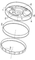
- FIG. 3 is an exploded perspective view of the rotor.
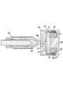
- FIG. 4 is a longitudinal sectional view showing a resin-bonded permanent magnet injection molding apparatus.
- First embodiment 5A and 5B show a second embodiment, in which FIG. 5A is a longitudinal sectional view of a rotor, and FIG. 5B is a perspective view of a yoke.
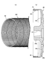
- (Second Embodiment) 6A and 6B show a third embodiment, in which FIG. 6A is a longitudinal sectional view of a rotor, and FIG.
- FIG. 6B is a perspective view of a yoke.
- FIG. 7A and 7B show a fourth embodiment, in which FIG. 7A is a longitudinal sectional view of a rotor, and FIG. 7B is a perspective view of a yoke.
- FIG. 8A and 8B show a fifth embodiment, in which FIG. 8A is a longitudinal sectional view of a rotor, and FIG. 8B is a perspective view of a yoke.
- FIG. 8A is a longitudinal sectional view of a rotor
- FIG. 8B is a perspective view of a yoke.
- the outer rotor type multipolar generator is used as an engine generator, for example.
- 11 is provided with a stator 12 fixed to a hollow support portion 11 a provided on the rotor 11 and a rotor 13 covering the stator 12. Is fixed.
- the stator 12 includes a ring-shaped stator core 15 formed by laminating and joining a plurality of magnetic steel plates, a synthetic resin bobbin 16 attached to the stator core 15, and the bobbin. 16 and a coil 17 wound around 16.
- Substantially T-shaped salient poles 15a are provided at a plurality of locations spaced at equal intervals in the circumferential direction of the outer circumference of the stator core 15, and the bobbin 16 is connected to the tip of the salient pole 15a and the stator core 15.
- the stator core 15 is formed so as to expose a part of both end surfaces and the inner peripheral surface, and the coil 17 is wound around the bobbin 16 at a portion corresponding to the salient pole 15a.
- Insertion holes 18 are provided in the inner peripheral portion of the stator core 15 at a plurality of locations spaced in the circumferential direction of the stator core 15, and bolts 19 inserted through the insertion holes 18 are provided in the support portion 11a.
- the stator 12 is fixed to the support portion 11a by screwing and tightening.
- the rotor 13 includes a hub 20 connected to the crankshaft 14, a cylindrical portion 21 having one end integrally connected to the hub 20, and an inner peripheral surface of the cylindrical portion 21.
- the hub 20 and the cylindrical portion 21 are integrally formed of a nonmagnetic material such as resin.
- the yoke 22A is formed in a cylindrical shape from a magnetic material.
- the yoke 22A which is an iron pipe, is fixed to the inner peripheral surface of the cylindrical portion 21 by press fitting.
- the hub 20 has a cylindrical support tube portion 20a into which the end portion of the crankshaft 14 is inserted and fixed, a ring portion 20b coaxially surrounding the support tube portion 20a, and a radial shape from the support tube portion 20a.
- a plurality of, for example, four connecting portions 20c that extend and are continuously connected to the ring portion 20b are integrally formed, and the cylindrical portion 21 is coaxially and integrally connected to the ring portion 20b. .
- the support cylinder 20a has a coaxial mounting hole 24 having a small diameter end at the end opposite to the engine body 11, and the end of the crankshaft 14 has the mounting hole at the end.
- a taper portion 14a to be fitted to 24 is formed.
- the support cylinder part 20a that is, the hub 20 is relatively located with respect to the crankshaft 14.
- a key 25 for preventing rotation is inserted, and a bolt 26 having an enlarged head portion 26a that comes into contact with and engages with the end surface of the support cylinder portion 20a opposite to the engine body 11 is connected to the crank. Screwed into the end of the shaft 14.
- the plurality of permanent magnets 23 are resin-bonded permanent magnets that are connected in series and integrated, and are polarized to the N pole and the S pole on the outer peripheral side and the inner peripheral side, and the polarity of the polarized poles is
- the poles adjacent to each other in the circumferential direction of the yoke 22A are mold-bonded to the inner peripheral surface of the yoke 22A so that the poles are different from the outer peripheral side and the inner peripheral side. Fixed and by a magnetic attractive force between the resin bonded magnet and the yoke).
- the mold device 27 includes the first mold 29, the second mold 30 that sandwiches the yoke 22A between the first mold 29, and the radially inner side of the yoke 22A.
- a ring-shaped magnetizing magnet 31 mounted on the first mold 29, and the cavity 32 is formed by the cooperation of the first mold 29, the second mold 30, the yoke 22A and the magnetizing magnet 31. It is formed.
- a sprue 33 connected to the nozzle 28 a at the tip of the injection machine 28, a plurality of gates 34 communicating with the cavity 32, and a runner 35 connecting the gates 34 and the sprue 33 are formed. Is done.
- a powder material 36 in which magnetic powder is covered with a resin to be coated is heated and melted and injected from the injection machine 28.
- the sprue 33, the runner 35 and the nozzles 28a of the injection machine 28 are used. It is injected into the cavity 32 through the gate 34.
- the material 36 heated and melted is magnetized by the magnetizing magnet 31 simultaneously with the molding in the cavity 32, and the permanent magnet 23, which is a resin-bonded permanent magnet integrated in a ring shape, is formed on the inner periphery of the yoke 22A. Mold bonded to the surface.
- the yoke 22A in which the permanent magnet 23 is molded and bonded to the inner peripheral surface in this way, is fixed to the inner peripheral surface of the cylindrical portion 21 by being press-fitted into the cylindrical portion 21 integrally connected to the hub 20.
- a hub 20 connected to the crankshaft 14 and a cylindrical portion 21 having one end connected to the hub 20 are integrally formed of a resin which is a nonmagnetic material. Since the yoke 22A is fixed to the inner peripheral surface of the cylindrical portion 21, it becomes easy to match the central axis of the hub 20 with the central axis of the inner peripheral surface of the cylindrical portion 21, and the yoke 22A is centered. Can be easy. Furthermore, the centering accuracy of the yoke 22A can be further improved by subjecting the taper-shaped mounting hole 24 of the support cylinder portion 20a of the hub 20 to additional cutting with reference to the central axis of the hub 20. . In addition, the thickness of the yoke 22A can be reduced, and the weight of the rotor 13 can be reduced due to the fact that the hub 20 and the cylindrical portion 21 are made of resin.
- the permanent magnet 23 fixed to the inner peripheral surface of the yoke 22A is a resin-bonded permanent magnet molded and bonded to the inner peripheral surface of the yoke 22A by injection molding, it has the same magnetomotive force as compared with the conventional ferrite magnet. It is possible to reduce the volume to be obtained, and it is possible to reduce the weight and facilitate the assembly of the permanent magnet 23.
- the resin-bonded permanent magnet formed by injection molding is molded on the inner peripheral surface of the yoke 22A before being fixed to the cylindrical portion 21, but the cylindrical portion integrated with the hub 20 is used. It is also possible to mold-bond a resin-bonded permanent magnet that is injection-molded to the inner peripheral surface of the yoke 22 ⁇ / b> A press-fitted into 21. Thereby, it becomes easy to match the center axis of the hub 20 with the center axis of the inner peripheral surface of the resin bonded magnet that is injection-molded on the inner peripheral surface of the yoke 22A, and centering can be facilitated.
- the hub 20 and the cylindrical portion 21 are integrally formed of resin.
- the hub 20 and the cylindrical portion 21 are made of a light alloy such as aluminum, magnesium, or titanium.
- the same effect can be achieved.
- the yoke 22B is formed by winding a magnetic metal strip 37 a plurality of times or only once (twice in this embodiment). May be configured.
- the yoke 22C may be configured such that a belt plate 38 made of magnetic metal is spirally wound.
- the yoke 22C may be formed by cutting the cylinder 38 into a necessary length as shown by a chain line in FIG.
- the yoke 22D is configured such that a wire rod 39 made of a magnetic metal and having a rectangular cross section is spirally wound.
- the yoke 22D may be formed by cutting the wire 39 into a required length as shown by a chain line in FIG.
- the yoke 22E is configured such that a wire 40 made of a magnetic metal and having a circular cross-sectional shape is spirally wound.
- the yoke 22E may be formed by cutting the wire 40 into a necessary length as shown by a chain line in FIG.
- the yoke 22E is fixed to the inner peripheral surface of the cylindrical portion 21 by being screwed into the cylindrical portion 21, but a female screw may be formed in advance on the inner peripheral surface of the cylindrical portion 21 for the screwing. Then, the center axis of the yoke 22E can be matched with the center axis of the hub 20 with high accuracy by increasing the accuracy of the female screw.
- the screwing direction of the yoke 22E into the cylindrical portion 21 is preferably set in the direction opposite to the rotation direction of the hub 20 and the cylindrical portion 21, that is, the direction of rotation of the crankshaft 14.
- the yoke 22E is screwed by the cylindrical portion 21 according to the rotation, and the yoke 22E is securely fixed to the inner peripheral surface of the cylindrical portion 21.
- a plurality of permanent magnets are composed of a plurality of single magnets that are composed of ferrite, rare earth, or bonded magnets and have N-pole and S-pole magnetic poles, and these single-piece magnets are arranged on the inner peripheral surface of the yoke in the circumferential direction.
- the adjacent single magnets may be arranged so that the polarities of the adjacent single magnets are different on the inner and outer peripheral sides.
Landscapes
- Engineering & Computer Science (AREA)
- Power Engineering (AREA)
- Iron Core Of Rotating Electric Machines (AREA)
- Permanent Magnet Type Synchronous Machine (AREA)
- Permanent Field Magnets Of Synchronous Machinery (AREA)
Abstract
固定のステータと、ステータを同軸に囲繞して円筒状に形成されるとともに駆動軸に連結される磁性材料製のヨークの内周面に複数の永久磁石が設けられるロータとを備えるアウターロータ型多極発電機において、駆動軸(14)に連結されるハブ(20)と、ハブ(20)に一端部が連なる円筒部(21)とが非磁性材料で一体に形成され、円筒部(21)の内周面にヨーク(22A)が固着される。これにより、軽量化を図りつつヨークの芯出しを容易としたロータ構造を提供することができる。
Description
本発明は、固定のステータと、該ステータを同軸に囲繞して円筒状に形成されるとともに駆動軸に連結される磁性材料製のヨークの内周面に複数の永久磁石が設けられるロータとを備えるアウターロータ型多極発電機に関し、特にロータ構造の改良に関する。
このようなアウターロータ型多極発電機は、特許文献1等で既に知られており、このものでは、アルミニウム等の軽合金によってダイカスト成形されて駆動軸に連結される端壁部材と、たとえば軟鋼によってステータを同軸に覆う円筒状に形成されて前記端壁部材の外周部に一端部が固着されるとともに内周に複数の永久磁石が固着されるヨークとで、ロータが構成されている。
上記特許文献1で開示されるものでは、駆動軸に連結される端壁部材に、その端壁部材とは別部材である円筒状のヨークが固着される構造のため、端壁部材の中心軸線と、ヨークの中心軸線とを合致させる「芯出し」が難しい。そこで端壁部材およびヨークを軟鉄によって一体に形成すれば「芯出し」が容易となるが、軟鉄の絞り加工で端壁部材およびヨークを一体に形成するのは難しく、また重量が大きくなってしまう。
本発明は、かかる事情に鑑みてなされたものであり、軽量化を図りつつヨークの芯出しを容易としたアウターロータ型多極発電機におけるロータ構造を提供することを目的とする。
上記目的を達成するために、本発明は、固定のステータと、該ステータを同軸に囲繞して円筒状に形成されるとともに駆動軸に連結される磁性材料製のヨークの内周面に複数の永久磁石が設けられるロータとを備えるアウターロータ型多極発電機において、前記駆動軸に連結されるハブと、該ハブに一端部が連なる円筒部とが非磁性材料で一体に形成され、前記円筒部の内周面に前記ヨークが固着されることを第1の特徴とする。
また本発明は、第1の特徴の構成に加えて、前記ハブおよび前記円筒部が、樹脂から成ることを第2の特徴とする。
本発明は、第1の特徴の構成に加えて、前記ハブおよび前記円筒部が、軽金属から成ることを第3の特徴とする。
本発明は、第1の特徴の構成に加えて、前記ヨークが、鉄管から成ることを第4の特徴とする。
本発明は、第1の特徴の構成に加えて、前記ヨークは、磁性金属製の帯板が複数回もしくは1回だけ巻回されて成ることを第5の特徴とする。
本発明は、第1の特徴の構成に加えて、前記ヨークは、磁性金属製の帯板が螺旋状に巻回されて成ることを第6の特徴とする。
本発明は、第1の特徴の構成に加えて、前記ヨークは、磁性金属製の線材が螺旋状に巻回されて成ることを第7の特徴とする。
さらに本発明は、第1~第7の特徴の構成のいずれかに加えて、前記永久磁石が、射出成形で前記ヨークの内周面にモールド結合される樹脂ボンド永久磁石であることを第8の特徴とする。
本発明の上記特徴によれば、駆動軸に連結されるハブと、内周面に円筒状のヨークが設けられる円筒部とが非磁性材料で一体に形成されるので、ハブの中心軸線と、円筒部の内周面の中心軸線とを合致させることは容易であり、ヨークの芯出しを容易としつつ、ヨークの肉厚を薄くしてロータの軽量化を図ることができる。
また特に第2の特徴によれば、ハブおよび円筒部が樹脂から成り、特に第3の特徴によれば、ハブおよび円筒部が軽金属から成るので、ロータをより軽量化することができる。
さらに特に第8の特徴の構成によれば、射出成形される樹脂ボンド永久磁石をヨークの内周面にモールド結合することで、より軽量化を図るとともに、ハブの中心軸線と、永久磁石の内周面の中心軸線とを合致させることが容易となり、ヨークの芯出しが容易となるので永久磁石の組付けを容易とすることができる。
12・・・ステータ
13・・・ロータ
14・・・駆動軸であるクランクシャフト
20・・・ハブ
21・・・円筒部
22A,22B,22C,22D,22E・・・ヨーク
23・・・永久磁石
37,38・・・帯板
39,40・・・線材
13・・・ロータ
14・・・駆動軸であるクランクシャフト
20・・・ハブ
21・・・円筒部
22A,22B,22C,22D,22E・・・ヨーク
23・・・永久磁石
37,38・・・帯板
39,40・・・線材
以下、本発明の実施の形態について添付の図面を参照しながら説明する。
本発明の第1の実施の形態について図1~図4を参照しながら説明すると、先ず図1において、このアウターロータ型多極発電機は、たとえばエンジン発電機として用いられるものであり、エンジン本体11に設けられる中空の支持部11aに固定されるステータ12と、そのステータ12を覆うロータ13とを備え、前記ステータ12と同軸に配置される駆動軸としてのクランクシャフト14の端部にロータ13が固定される。
図2を併せて参照して、前記ステータ12は、複数枚の磁性鋼板が積層、結合されて成るリング状のステータコア15と、該ステータコア15に装着される合成樹脂製のボビン16と、該ボビン16に巻装されるコイル17とを備える。
前記ステータコア15の外周の周方向に等間隔をあけた複数箇所には略T字状の突極15aが突設されており、前記ボビン16は、前記突極15aの先端部ならびに前記ステータコア15の両端面の一部および内周面を露出させるようにしてステータコア15を覆うように形成されており、前記突極15aに対応する部分で前記ボビン16に前記コイル17が巻装される。
前記ステータコア15の周方向に間隔をあけた複数箇所で前記ステータコア15の内周部には、挿通孔18が設けられており、それらの挿通孔18に挿通されるボルト19を前記支持部11aに螺合して締め付けることによって前記ステータ12が前記支持部11aに固定される。
図3を併せて参照して、前記ロータ13は、前記クランクシャフト14に連結されるハブ20と、該ハブ20に一端部が一体に連なる円筒部21と、その円筒部21の内周面に固着される円筒状のヨーク22Aと、該ヨーク22Aの内周面に設けられる複数の永久磁石23とで構成される。
前記ハブ20および前記円筒部21は、非磁性材料たとえば樹脂によって一体に形成される。前記ヨーク22Aは、磁性材料により円筒状に形成されるものであり、この第1の実施の形態では、鉄管である前記ヨーク22Aが前記円筒部21の内周面に圧入によって固着される。
前記ハブ20は、前記クランクシャフト14の端部が挿通、固着される円筒状の支持筒部20aと、その支持筒部20aを同軸に囲繞するリング部20bと、前記支持筒部20aから放射状に延びて前記リング部20bに連設される複数個たとえば4個の連結部20cとを一体に有するものであり、前記リング部20bに前記円筒部21が同軸にかつ一体に連なるように形成される。
前記支持筒部20aは、前記エンジン本体11とは反対側の端部を小径端としたテーパ状の取付け孔24を同軸に有しており、前記クランクシャフト14の端部には、前記取付け孔24に嵌合されるテーパ部14aが形成される。前記支持筒部20aと、該支持筒部20aの前記テーパ孔24に嵌合される前記クランクシャフト14の前記テーパ部14aとの間には、クランクシャフト14に対する支持筒部20aすなわちハブ20の相対回転を阻止するためのキー25が嵌入されており、前記支持筒部20aの前記エンジン本体11とは反対側の端面に当接、係合される拡径頭部26aを有するボルト26が前記クランクシャフト14の端部に螺合される。
複数の前記永久磁石23は、一連につながって一体となっている樹脂ボンド永久磁石であり、その外周側および内周側でN極およびS極に分極されるとともに、分極された極の極性が前記ヨーク22Aの周方向で隣接する極同士では前記外周側および前記内周側で異なるようにしつつ全体としてリング状になるように、前記ヨーク22Aの内周面にモールド結合(型成形による樹脂の固着および樹脂ボンド磁石とヨークとの磁気吸引力により)される。
前記永久磁石23の射出成形にあたっては、図4で示すように、金型装置27と、射出機28とが用いられる。金型装置27は、第1金型29と、第1金型29との間にヨーク22Aを挟持する第2金型30と、前記ヨーク22Aの半径方向内方に配置されるようにして前記第1金型29に装着されるリング状の着磁用磁石31とを備え、第1金型29、第2金型30、前記ヨーク22Aおよび前記着磁用磁石31の協働でキャビティ32が形成される。
第2金型30には、射出機28の先端のノズル28aに接続されるスプルー33と、前記キャビティ32に通じる複数のゲート34と、それらのゲート34および前記スプルー33間を結ぶランナー35が形成される。コーティングされる樹脂で磁粉が覆われて成る粉末状の材料36は、加熱溶融されて前記射出機28から射出されるものであり、射出機28の前記ノズル28aから前記スプルー33、前記ランナー35および前記ゲート34を経て前記キャビティ32に注入される。加熱溶融された前記材料36は前記キャビティ32での成形と同時に前記着磁用磁石31によって着磁され、リング状に一体となった樹脂ボンド永久磁石である永久磁石23が前記ヨーク22Aの内周面にモールド結合される。
このようにして内周面に永久磁石23がモールド結合されたヨーク22Aは、前記ハブ20に一体に連なった前記円筒部21に圧入されることで、該円筒部21の内周面に固着される。
次にこの第1の実施の形態の作用について説明すると、クランクシャフト14に連結されるハブ20と、該ハブ20に一端部が連なる円筒部21とが非磁性材料である樹脂で一体に形成され、前記円筒部21の内周面にヨーク22Aが固着されるので、ハブ20の中心軸線と、円筒部21の内周面の中心軸線とを合致させることが容易となり、ヨーク22Aの芯出しを容易とすることができる。さらに前記ハブ20における前記支持筒部20aが有するテーパ状の取付け孔24に、ハブ20の中心軸線を基準として追加の切削加工を施すことによってヨーク22Aの芯出しの精度をより一層高めることができる。しかもヨーク22Aの肉厚を薄くすることができ、ハブ20および円筒部21が樹脂から成ることと相俟ってロータ13の軽量化を図ることができる。
またヨーク22Aの内周面に固着される永久磁石23が、射出成形で前記ヨーク22Aの内周面にモールド結合される樹脂ボンド永久磁石であるので、従来のフェライト磁石に比べて同じ起磁力を得るための体積が少なくてすみ、より軽量化を図るとともに永久磁石23の組付けを容易とすることができる。
上述の第1の実施の形態では、円筒部21に固着される前のヨーク22Aの内周面に射出成形される樹脂ボンド永久磁石をモールド結合するようにしたが、ハブ20と一体の円筒部21に圧入されたヨーク22Aの内周面に射出成形される樹脂ボンド永久磁石をモールド結合することも可能である。これにより、ハブ20の中心軸線と、ヨーク22Aの内周面に射出成形される樹脂ボンド磁石の内周面の中心軸線とを合致させることが容易となり、芯出しを容易とすることができる。
また上述の第1の実施の形態では、ハブ20および円筒部21が樹脂で一体に形成されていたが、前記ハブ20および前記円筒部21が、軽合金たとえばアルミニウム、マグネシウムまたはチタンから成るようにしても同様の効果を奏することができる。
本発明の第2の実施の形態として、図5で示すように、磁性金属製の帯板37が複数回もしくは1回だけ(この実施の形態では2回)巻回されて成るようにヨーク22Bを構成してもよい。
本発明の第3の実施の形態として、図6で示すように、磁性金属製の帯板38が螺旋状に巻回されて成るようにヨーク22Cを構成してもよく、この場合、帯板38が螺旋状に巻回されて長く延びる円筒部から図6(b)の鎖線で示すように必要長さに切断することで、ヨーク22Cが形成されるようにすればよい。
また本発明の第4の実施の形態として、図7で示すように、磁性金属から成るとともに横断面形状を矩形とした線材39が螺旋状に巻回されて成るようにヨーク22Dを構成してもよく、この場合、線材39が螺旋状に巻回されて長く延びる円筒部から図7(b)の鎖線で示すように必要長さに切断することで、ヨーク22Dが形成されればよい。
さらに本発明の第5の実施の形態として、図8で示すように、磁性金属から成るとともに横断面形状を円形とした線材40が螺旋状に巻回されて成るようにヨーク22Eを構成してもよく、この場合、線材40が螺旋状に巻回されて長く延びる円筒部から図8(b)の鎖線で示すように必要長さに切断することで、ヨーク22Eが形成されればよい。しかも前記ヨーク22Eは前記円筒部21内にねじ込むことで該円筒部21の内周面に固着されるが、そのねじ込みにあたって前記円筒部21の内周面に予め雌ねじが形成されていてもよく、そうすればその雌ねじの精度を高めることでヨーク22Eの中心軸線をハブ20の中心軸線に精度よく合致させることができる。また前記ヨーク22Eの前記円筒部21へのねじ込み方向は前記ハブ20および前記円筒部21の回転方向すなわち前記クランクシャフト14の回転方向と反対方向とすることが望ましく、そうすれば前記クランクシャフト14の回転に応じて前記ヨーク22Eが前記円筒部21によりねじ込まれる効果が得られ、前記ヨーク22Eが前記円筒部21の内周面により確実に固着される。
以上、本発明の実施の形態について説明したが、本発明は上記実施の形態に限定されるものではなく、その要旨を逸脱することなく種々の設計変更を行うことが可能である。たとえば複数の永久磁石が、フェライト、希土類またはボンド磁石によって構成されてN極、S極の磁極を持つ複数の単体磁石で構成され、それらの単体磁石が、ヨークの内周面に、その周方向で隣接する単体磁石同士の極性が内周側および外周側で異なるように配置されてもよい。
Claims (8)
- 固定のステータ(12)と、該ステータ(12)を同軸に囲繞して円筒状に形成されるとともに駆動軸(14)に連結される磁性材料製のヨーク(22A,22B,22C,22D,22E)の内周面に複数の永久磁石(23)が設けられるロータ(13)とを備えるアウターロータ型多極発電機において、前記駆動軸(14)に連結されるハブ(20)と、該ハブ(20)に一端部が連なる円筒部(21)とが非磁性材料で一体に形成され、前記円筒部(21)の内周面に前記ヨーク(22A~22E)が固着されることを特徴とするアウターロータ型多極発電機におけるロータ構造。
- 前記ハブ(20)および前記円筒部(21)が、樹脂から成ることを特徴とする請求項1に記載のアウターロータ型多極発電機におけるロータ構造。
- 前記ハブ(20)および前記円筒部(21)が、軽金属から成ることを特徴とする請求項1に記載のアウターロータ型多極発電機におけるロータ構造。
- 前記ヨーク(22A)が、鉄管から成ることを特徴とする請求項1に記載のアウターロータ型発電機におけるロータ構造。
- 前記ヨーク(22B)は、磁性金属製の帯板(37)が複数回もしくは1回だけ巻回されて成ることを特徴とする請求項1に記載のアウターロータ型多極発電機におけるロータ構造。
- 前記ヨーク(22C)は、磁性金属製の帯板(38)が螺旋状に巻回されて成ることを特徴とする請求項1に記載のアウターロータ型多極発電機におけるロータ構造。
- 前記ヨーク(22D,22E)は、磁性金属製の線材(39,40)が螺旋状に巻回されて成ることを特徴とする請求項1に記載のアウターロータ型多極発電機におけるロータ構造。
- 前記永久磁石(23)が、射出成形で前記ヨーク(22A~22E)の内周面にモールド結合される樹脂ボンド永久磁石であることを特徴とする請求項1~7のいずれか1項に記載のアウターロータ型多極発電機におけるロータ構造。
Applications Claiming Priority (2)
| Application Number | Priority Date | Filing Date | Title |
|---|---|---|---|
| JP2016083979A JP2017195690A (ja) | 2016-04-19 | 2016-04-19 | アウターロータ型多極発電機におけるロータ構造 |
| JP2016-083979 | 2016-04-19 |
Publications (1)
| Publication Number | Publication Date |
|---|---|
| WO2017183378A1 true WO2017183378A1 (ja) | 2017-10-26 |
Family
ID=60115801
Family Applications (1)
| Application Number | Title | Priority Date | Filing Date |
|---|---|---|---|
| PCT/JP2017/011430 WO2017183378A1 (ja) | 2016-04-19 | 2017-03-22 | アウターロータ型多極発電機におけるロータ構造 |
Country Status (2)
| Country | Link |
|---|---|
| JP (1) | JP2017195690A (ja) |
| WO (1) | WO2017183378A1 (ja) |
Cited By (2)
| Publication number | Priority date | Publication date | Assignee | Title |
|---|---|---|---|---|
| WO2020090447A1 (ja) * | 2018-10-30 | 2020-05-07 | 株式会社デンソー | 回転電機 |
| WO2022065306A1 (ja) | 2020-09-25 | 2022-03-31 | ダイキン工業株式会社 | モータ、送風機、および、空気調和装置 |
Families Citing this family (3)
| Publication number | Priority date | Publication date | Assignee | Title |
|---|---|---|---|---|
| JP7326792B2 (ja) * | 2019-03-19 | 2023-08-16 | 株式会社デンソー | 回転電機、及び回転子の製造方法 |
| JP7379011B2 (ja) * | 2019-08-09 | 2023-11-14 | ミネベアミツミ株式会社 | 回転機器 |
| DE102022210700A1 (de) | 2022-10-11 | 2024-04-11 | Robert Bosch Gesellschaft mit beschränkter Haftung | Elektronisch kommutierter Elektromotor in Außenläuferbauart und Verfahren zu dessen Herstellung |
Citations (2)
| Publication number | Priority date | Publication date | Assignee | Title |
|---|---|---|---|---|
| JP2005287107A (ja) * | 2004-03-26 | 2005-10-13 | Aisin Seiki Co Ltd | 回転電機のロータ |
| JP2005341791A (ja) * | 2004-05-22 | 2005-12-08 | Minebea Co Ltd | モータ、特にスピンドルモータ |
-
2016
- 2016-04-19 JP JP2016083979A patent/JP2017195690A/ja active Pending
-
2017
- 2017-03-22 WO PCT/JP2017/011430 patent/WO2017183378A1/ja active Application Filing
Patent Citations (2)
| Publication number | Priority date | Publication date | Assignee | Title |
|---|---|---|---|---|
| JP2005287107A (ja) * | 2004-03-26 | 2005-10-13 | Aisin Seiki Co Ltd | 回転電機のロータ |
| JP2005341791A (ja) * | 2004-05-22 | 2005-12-08 | Minebea Co Ltd | モータ、特にスピンドルモータ |
Cited By (2)
| Publication number | Priority date | Publication date | Assignee | Title |
|---|---|---|---|---|
| WO2020090447A1 (ja) * | 2018-10-30 | 2020-05-07 | 株式会社デンソー | 回転電機 |
| WO2022065306A1 (ja) | 2020-09-25 | 2022-03-31 | ダイキン工業株式会社 | モータ、送風機、および、空気調和装置 |
Also Published As
| Publication number | Publication date |
|---|---|
| JP2017195690A (ja) | 2017-10-26 |
Similar Documents
| Publication | Publication Date | Title |
|---|---|---|
| WO2017183378A1 (ja) | アウターロータ型多極発電機におけるロータ構造 | |
| US8729760B2 (en) | Rotor of electric motor having structure for attaching magnet securely to outer circumferential surface of rotor core and manufacturing method thereof | |
| EP2573917B1 (en) | Method of producing a rotor and an inner rotor type brushless motor | |
| US7504753B2 (en) | Motor | |
| CN107534378B (zh) | 无槽无刷直流马达/致动器 | |
| JP2007074776A (ja) | 回転電機 | |
| US10848037B2 (en) | Permanent magnet rotor, method for the production thereof using a magnetizing fixture | |
| JP5501660B2 (ja) | 電動モータ及びそのロータ | |
| TW200631279A (en) | Axial-gap type motor | |
| KR102082573B1 (ko) | 요크 권선을 가진 능동 방사형 자기 베어링 | |
| CN102570669A (zh) | 端板和用于旋转电机的使用该端板的转子 | |
| US20150162791A1 (en) | Rotor and motor including the same | |
| MY136315A (en) | Motor | |
| WO2020059654A1 (ja) | アウターロータ型電動機用ロータ | |
| JP2007267574A (ja) | ロータの製造方法及び電動パワーステアリング用モータ | |
| CN106253518A (zh) | 转子、马达以及转子的制造方法 | |
| JPH11243654A (ja) | 回転電機用磁石回転子 | |
| US10418870B2 (en) | Synchronous reluctance motor with magnetic leakage path saturated by permanent magnets | |
| US9787153B2 (en) | Outer rotor type dynamo | |
| JP2018023218A (ja) | アウターロータ型多極発電機におけるロータ構造 | |
| JP2008099445A (ja) | 回転電機のインナロータ | |
| JP3187632U (ja) | ハイブリッド型ステッピングモータ用ロータ | |
| JP4680875B2 (ja) | ステータコアの製造方法 | |
| JP2018201308A (ja) | モータ及びモータの製造方法 | |
| JP2005295789A (ja) | インナーロータ型モータ用のステータユニット、インナーロータ型モータ用のステータユニットの製造方法及びそのステータユニットを備えるインナーロータ型モータ |
Legal Events
| Date | Code | Title | Description |
|---|---|---|---|
| DPE1 | Request for preliminary examination filed after expiration of 19th month from priority date (pct application filed from 20040101) | ||
| NENP | Non-entry into the national phase |
Ref country code: DE |
|
| 121 | Ep: the epo has been informed by wipo that ep was designated in this application |
Ref document number: 17785720 Country of ref document: EP Kind code of ref document: A1 |
|
| 122 | Ep: pct application non-entry in european phase |
Ref document number: 17785720 Country of ref document: EP Kind code of ref document: A1 |