WO2017179626A1 - ミキサ車及びミキサ車管理システム - Google Patents
ミキサ車及びミキサ車管理システム Download PDFInfo
- Publication number
- WO2017179626A1 WO2017179626A1 PCT/JP2017/015003 JP2017015003W WO2017179626A1 WO 2017179626 A1 WO2017179626 A1 WO 2017179626A1 JP 2017015003 W JP2017015003 W JP 2017015003W WO 2017179626 A1 WO2017179626 A1 WO 2017179626A1
- Authority
- WO
- WIPO (PCT)
- Prior art keywords
- mixer
- fluidity
- contents
- change
- slump
- Prior art date
- Legal status (The legal status is an assumption and is not a legal conclusion. Google has not performed a legal analysis and makes no representation as to the accuracy of the status listed.)
- Ceased
Links
Images





Classifications
-
- B—PERFORMING OPERATIONS; TRANSPORTING
- B28—WORKING CEMENT, CLAY, OR STONE
- B28C—PREPARING CLAY; PRODUCING MIXTURES CONTAINING CLAY OR CEMENTITIOUS MATERIAL, e.g. PLASTER
- B28C5/00—Apparatus or methods for producing mixtures of cement with other substances, e.g. slurries, mortars, porous or fibrous compositions
- B28C5/42—Apparatus specially adapted for being mounted on vehicles with provision for mixing during transport
-
- B—PERFORMING OPERATIONS; TRANSPORTING
- B28—WORKING CEMENT, CLAY, OR STONE
- B28C—PREPARING CLAY; PRODUCING MIXTURES CONTAINING CLAY OR CEMENTITIOUS MATERIAL, e.g. PLASTER
- B28C7/00—Controlling the operation of apparatus for producing mixtures of clay or cement with other substances; Supplying or proportioning the ingredients for mixing clay or cement with other substances; Discharging the mixture
-
- B—PERFORMING OPERATIONS; TRANSPORTING
- B60—VEHICLES IN GENERAL
- B60P—VEHICLES ADAPTED FOR LOAD TRANSPORTATION OR TO TRANSPORT, TO CARRY, OR TO COMPRISE SPECIAL LOADS OR OBJECTS
- B60P3/00—Vehicles adapted to transport, to carry or to comprise special loads or objects
- B60P3/16—Vehicles adapted to transport, to carry or to comprise special loads or objects for carrying mixed concrete, e.g. having rotatable drums
-
- G—PHYSICS
- G01—MEASURING; TESTING
- G01N—INVESTIGATING OR ANALYSING MATERIALS BY DETERMINING THEIR CHEMICAL OR PHYSICAL PROPERTIES
- G01N11/00—Investigating flow properties of materials, e.g. viscosity, plasticity; Analysing materials by determining flow properties
-
- G—PHYSICS
- G01—MEASURING; TESTING
- G01N—INVESTIGATING OR ANALYSING MATERIALS BY DETERMINING THEIR CHEMICAL OR PHYSICAL PROPERTIES
- G01N33/00—Investigating or analysing materials by specific methods not covered by groups G01N1/00 - G01N31/00
- G01N33/38—Concrete; Lime; Mortar; Gypsum; Bricks; Ceramics; Glass
Definitions
- the present invention relates to a mixer vehicle and a mixer vehicle management system capable of appropriately managing the quality of the contents of the mixer drum, for example.
- a truck mixer or agitator truck equipped with a mixer drum that can accommodate ready-mixed concrete such as mortar or ready-mixed concrete (hereinafter referred to as “ready concrete”) is moved from the ready-mix factory to the concrete placement site. It is widely used for transporting live concrete.
- the ready-mixed concrete is produced, for example, by kneading a predetermined amount of cement, sand, gravel, water or the like with a mixer device in a ready-mixed factory.
- the produced ready-mixed concrete is put into the mixer drum and transported to the designated concrete placement site after the completion of the feeding.
- the ready-mixed concrete introduced into the mixer drum at the ready-mixed factory is transported while being stirred in the mixer drum that rotates forward at a predetermined rotational speed. Thereby, the state in which cement, aggregate (sand, gravel, etc.) and water are uniformly kneaded is maintained, and separation due to the difference in specific gravity of these raw materials is prevented. Then, the ready-mixed rice starts to solidify by condensation from the time when the raw materials are mixed. For this reason, the operation schedule of the mixer truck including the mixing of raw concrete, mixing into the mixer drum, transportation, and discharge at the placement site are managed so that slump (hardness) suitable for driving can be provided to the placement site. (For example, refer to Patent Document 1).
- the strength of concrete is mainly determined by the mixing ratio of cement and water, and the strength of concrete tends to increase as the ratio of water to cement decreases.
- the required strength of concrete varies depending on the type of concrete product, etc., and the required quality of the ready-mixed concrete (slump reference value) often varies depending on the site of placement.
- the slump of the live control unit transported to the placement site does not meet the standard value, it may become unusable in the worst case. Under such circumstances, there is a problem that the slump is illegally operated (illegal water addition) due to the addition of the raw kon to the raw kon in the mixer drum during the conveyance of the raw kon or at the installation site.
- Patent Document 1 in order to monitor illegal water addition, a sensor for detecting the load of the mixer truck is attached to the mixer truck, and the mixing ratio of cement and water is managed based on the output of the sensor.
- a mixed vehicle support management system is described.
- an object of the present invention is to provide a mixer vehicle and a mixer vehicle management system capable of determining the presence or absence of water added to the ready-mixed concrete.
- a mixer truck includes a mixer drum that contains contents, a drive device, a detection unit, and an evaluation unit.
- the driving device generates a driving force for rotating the mixer drum.
- the detection unit detects information related to at least one of the driving force and the temperature of the contents.
- the evaluation unit evaluates a change in fluidity of the content with time based on the output of the detection unit.
- the evaluation unit is configured to evaluate a change in fluidity of the content over time based on information related to at least one of a driving force for rotating the mixer drum and a temperature of the content of the mixer drum. ing. This makes it possible to accurately grasp the change in fluidity over time without being affected by traveling vibration during transportation, and to appropriately evaluate the quality of the contents including the presence or absence of abnormality.
- the above contents are typically ready-mixed concrete (ready concrete) such as mortar and ready-mix concrete, and the fluidity of the contents typically includes a slump or a slump flow of ready-made concrete.
- the evaluation unit is typically configured to evaluate the time change of the fluidity of the contents based on the time change of the output of the detection unit. Thereby, for example, it becomes possible to appropriately monitor the presence or absence of water addition to the raw kon.
- the evaluation unit determines that the temporal change in fluidity of the contents is normal, and the increase amount of the output of the detection unit is When the value is equal to or less than the predetermined value, it may be configured to determine that the change in fluidity of the content with time is abnormal.
- the evaluation unit determines that the temporal change in fluidity of the contents is normal, and the amount of change in the driving force is equal to or less than the predetermined value. In some cases, it may be determined that the temporal change in the fluidity of the contents is abnormal only when the temperature of the contents is lowered.
- the mixer truck may further include a first storage unit that stores a blending ratio of raw materials constituting the contents.
- the evaluation unit calculates an estimated value of the driving force of the mixer drum or the temperature of the content after a predetermined time based on the mixing ratio of the raw materials, and outputs the detection unit and the estimated value. Is determined to be normal and the difference between the output of the detection unit and the estimated value is not within the predetermined range. Is configured to determine that the temporal change in fluidity of the contents is abnormal.
- the mixer vehicle may further include a second storage unit that can store an evaluation result by the evaluation unit.
- the evaluation unit determines that the temporal change in the fluidity of the content is abnormal
- the information on the fluidity over a predetermined time before and after the time determined to be the abnormal is described above. It is comprised so that it may memorize
- the mixer vehicle may further include an issuing device that issues a document that describes a result of evaluating the change in fluidity of the contents with time by the evaluation unit. This makes it possible to provide proof of the quality of the contents on the spot in response to a request from the user or customer.
- the information related to the driving force typically includes driving pressure, driving torque, and the like.
- the detection unit includes a pressure sensor that detects a driving pressure of the mixer drum or a torque sensor that detects a driving torque of the mixer drum.
- the detection unit may include a temperature sensor that is attached to the mixer drum and detects the temperature of the contents.
- the mixer vehicle may further include a communication unit capable of communicating with the management server.
- the evaluation unit is configured to control the communication unit so as to transmit the evaluation result to the management server when evaluating that the temporal change in the fluidity of the contents is abnormal. The Thereby, the quality control function of the contents can be provided to the management system of the mixer truck.
- the mixer vehicle may further include a determination unit that determines a vehicle state.
- the said evaluation part may perform fluidity
- the evaluation unit is typically configured to evaluate a change in fluidity of the content with time during the stirring rotation of the content by the mixer drum.
- a mixer truck management system includes a mixer truck and a management server.
- the mixer vehicle includes a mixer drum for storing contents, a driving device that generates a driving force for rotating the mixer drum, and a detection unit that detects information related to at least one of the driving force and the temperature of the contents.
- the mixer vehicle communication unit communicable with the management server, and the change of the fluidity of the contents can be acquired based on the output of the detection unit, and the change of the acquired change of the fluidity is managed as described above.
- a mixer vehicle control unit capable of controlling the mixer vehicle communication unit to transmit to the server.
- the management server can control the server communication unit so as to receive a server communication unit capable of communicating with the mixer vehicle and the transmitted time change of the fluidity, and the received time change of the fluidity
- a server control unit configured to determine whether or not is normal.
- FIG. 1 is a plan view of a mixer truck according to an embodiment of the present invention
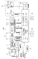
- FIG. 2 is a block diagram showing a hardware configuration of the mixer truck.
- the overall configuration of the mixer vehicle 100 of the present embodiment will be described with reference to FIGS. 1 and 2.
- the mixer truck 100 includes a mixer drum 2 that accommodates ready-mixed concrete (ready concrete) such as mortar and ready-mixed concrete and transports it to a construction site of civil engineering or architecture.
- the mixer vehicle 100 includes an operator cab 11, a gantry 1, a mixer drum 2 that is mounted on the gantry 1 and can accommodate raw concrete, a drive device 4 that rotationally drives the mixer drum 2, and a controller that controls each block of the mixer vehicle 100. 10 and.
- the mixer drum 2 is a bottomed cylindrical container that is rotatably mounted on the gantry 1 so as to be able to agitate and discharge raw concrete.
- the mixer drum 2 is mounted such that the rotating shaft faces the front-rear direction of the vehicle.
- the mixer drum 2 is mounted so as to be inclined forward and backward so as to gradually increase toward the rear of the vehicle.
- An opening is formed at the rear end of the mixer drum 2, and it is configured such that raw food can be charged and discharged from the opening.
- the mixer drum 2 is rotationally driven using a traveling engine 3 mounted on the mixer vehicle 100 as a power source.
- An engine dedicated to the mixer drum other than the traveling engine 3 may be provided. In this case, the mixer drum is rotationally driven using the dedicated engine as a power source.
- the mixer drum 2 is provided with a temperature sensor 2a as a temperature detector (second detection unit) that detects information related to the temperature of the raw control unit accommodated therein.
- the configuration and installation location of the temperature sensor 2a are not particularly limited as long as the temperature of the raw control can be detected directly or indirectly.
- the temperature sensor 2 a is configured by one or a plurality of thermoelectric elements installed inside the mixer drum 2. As shown in FIG. 2, the temperature sensor 2 a transmits a raw temperature signal related to the detected temperature of the raw concrete to the controller 10.
- the driving device 4 includes a fluid circuit that is driven by the rotation of the engine 3 and generates a driving force for rotating the mixer drum 2 by the fluid pressure of the working fluid.
- the rotational movement of the crankshaft in the engine 3 is caused by a power take-out mechanism 9 (PTO: Power-Take-Off) for constantly taking power from the engine 3 and a drive shaft 8 connecting the power take-out mechanism 9 and the drive device 4. Is transmitted to the driving device 4.
- PTO Power-Take-Off
- the power take-out mechanism 9 is provided with a rotation sensor 9 a that detects the rotation speed and transmits a rotation speed signal corresponding to the detected rotation speed to the controller 10.
- the rotation sensor 9a may be provided so as to detect the rotational speed of the drive shaft 8.
- the driving device 4 hydraulic oil is used as the working fluid. Instead of hydraulic oil, other incompressible fluids may be used as the hydraulic fluid.
- the driving device 4 includes a hydraulic pump 5 as a fluid pressure pump that is driven by the engine 3 and discharges a working fluid, and a hydraulic motor 6 as a fluid pressure motor that is driven by the hydraulic pump 5 to rotationally drive the mixer drum 2. .
- the drive device 4 can forward / reverse and increase / decrease the mixer drum 2.
- the hydraulic pump 5 is rotationally driven by the power that is always taken out from the engine 3 through the power take-out mechanism 9. Therefore, the rotational speed of the hydraulic pump 5 is greatly affected by a change in the rotational speed of the engine 3 accompanying the traveling state of the vehicle. Therefore, the mixer vehicle 100 controls the operation of the hydraulic pump 5 and the hydraulic motor 6 by the controller 10 so that the mixer drum 2 is in the target rotation state according to the rotational speed of the engine 3.
- the hydraulic pump 5 is, for example, a swash plate type axial piston pump having a variable capacity.
- the hydraulic pump 5 receives a command signal from the controller 10, adjusts the tilt angle of the pump to make the discharge amount variable, and switches the discharge direction (the rotation direction of the drum) with a valve.
- the hydraulic pump 5 may be configured to receive a command signal from the controller 10 and switch the tilt angle of the pump to the forward rotation direction or the reverse rotation direction.
- the hydraulic pump 5 has an electromagnetic valve for adjusting the tilt angle. By switching the solenoid valve, the discharge direction and discharge capacity of the hydraulic pump 5 are adjusted.
- the hydraulic oil discharged from the hydraulic pump 5 is supplied to the hydraulic motor 6, and the hydraulic motor 6 rotates thereby.
- the mixer drum 2 is connected to the hydraulic motor 6 via a speed reducer 7. As a result, the mixer drum 2 rotates as the hydraulic motor 6 rotates.
- the mixer vehicle 100 includes a first detection unit that detects information related to the driving force of the driving device 4 that rotates the mixer drum 2.
- a first detection unit a pressure sensor for detecting the driving pressure of the mixer drum 2 or a torque sensor for detecting the driving torque of the mixer drum 2 is used.
- the pressure sensor 4a is used. As shown in FIG. 2, the pressure sensor 4 a transmits a load pressure signal corresponding to the detected hydraulic oil pressure to the controller 10.
- the pressure sensor 4a may be provided so as to be able to detect the discharge pressure of the hydraulic pump 5, or may be provided so as to be able to detect the discharge pressure of the hydraulic motor 6. Alternatively, the pressure sensor 4 a may be provided so as to be able to detect the pressure of the hydraulic oil supplied from the hydraulic pump 5 to the hydraulic motor 6.
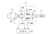
- FIG. 3 is a schematic configuration diagram of the driving device 4 showing an installation example of the pressure sensor 4a (4a1, 4a2).
- the hydraulic pump 5 and the hydraulic motor 6 are connected to each other via the first pipeline 4b1 and the second pipeline 4b2.
- the first pipeline 4b1 is connected between the first outlet of the hydraulic pump 5 and the first inlet of the hydraulic motor 6, and the second pipeline 4b2 is hydraulically connected to the second outlet of the hydraulic pump 5.
- a second inlet of the motor 6 is connected.
- the pressure sensor 4a includes a first pressure sensor 4a1 provided in the first pipeline 4b1 and a second pressure sensor 4a2 provided in the second pipeline 4b2.
- the first pressure sensor 4a1 mainly detects a hydraulic pressure (driving pressure) when the mixer drum 2 is rotated forward
- the second pressure sensor 4a2 mainly detects a hydraulic pressure (driving pressure) when the mixer drum 2 is rotated reversely. Is detected.
- the first pressure sensor 4a1 detects a driving pressure that causes the mixer drum 2 to rotate forward during stirring of the raw concrete. Therefore, in the following description, the output of the pressure sensor 4a means the output of the first pressure sensor 4a1 unless otherwise specified.
- the second pressure sensor 4a2 may be omitted as necessary.
- the hydraulic motor 6 is, for example, a swash plate type axial piston motor having a variable capacity.
- the hydraulic motor 6 is rotationally driven in response to the supply of hydraulic oil discharged from the hydraulic pump 5.
- the hydraulic motor 6 includes an electromagnetic valve that receives a command signal from the controller 10 and adjusts the tilt angle of the motor. By switching this electromagnetic valve, the capacity of the hydraulic motor 6 is switched in two stages, a small capacity for high speed rotation and a large capacity for normal rotation.
- Controller 10 controls each block of drive device 4 and other mixer vehicle 100.
- the controller 10 is a microcomputer having a CPU (Central Processing Unit) 110, an EEPROM (Electrically-Erasable Programmable Read-Only Memory) 120, and a RAM (Random Access Memory) 130.
- CPU Central Processing Unit
- EEPROM Electrically-Erasable Programmable Read-Only Memory
- RAM Random Access Memory
- the CPU 110 appropriately accesses the EEPROM 120, the RAM 130, etc. as necessary, and comprehensively controls each block of the mixer vehicle 100 while performing various arithmetic processes.
- the EEPROM 120 is a non-volatile memory such as a flash memory (SSD: Solid State Drive) or other solid-state memory.
- the EEPROM 120 is a nonvolatile memory in which firmware such as an OS, a program, various parameters, and the like to be executed by the CPU 110 is fixedly stored.
- the EEPROM 120 functions as a storage unit capable of storing a result of an evaluation process executed in a slump evaluation unit 111 described later.
- the EEPROM 120 also stores a program for executing the fluidity evaluation process in the slump evaluation unit 111, a blending ratio of raw materials constituting raw concrete to be input to the mixer drum 2, and the like. Note that a storage device other than the EEPROM 120 may be used as the storage unit.
- the RAM 130 is used as a work area for the CPU 110 and temporarily holds the OS, various applications being executed, and various data being processed.
- the CPU 110 has a slump evaluation unit 111.
- the slump evaluation unit 111 is configured to acquire the output of the pressure sensor 4a at predetermined time intervals when the hydraulic pump 5 is driven, and to evaluate the change over time in the fluidity of the raw cooking fluid in the mixer drum 2.
- the slump evaluation unit 111 starts a timer from the start of rotation of the mixer drum 2, and stores a load pressure signal received from the pressure sensor 4a every predetermined time (for example, several seconds to several minutes) in the EEPROM 120 or the RAM 130.
- the change in the driving pressure of the mixer drum 2 is monitored based on the load pressure signal.
- the slump evaluation unit 111 evaluates the time change of the fluidity (slump) of the raw cooking fluid in the mixer drum 2 based on the time change (for example, change rate) of the driving pressure of the mixer drum 2 or the change amount thereof.
- the obtained evaluation result is stored (saved) in, for example, the EEPROM 120 or the RAM 130.
- the ready-mixed concrete introduced into the mixer drum 2 is agitated by the mixer drum 2 that rotates forward at a predetermined constant rotational speed. Since the ready-mixed food is solidified by a hydration reaction between cement and water, the flowability of the ready-mixed food gradually decreases with the progress of the reaction (with time). Therefore, the driving pressure necessary to drive the mixer drum 2 to rotate at a predetermined rotational speed is gradually increased with time.
- FIG. 4A schematically shows an example of the change over time of the driving pressure of the mixer drum 2 during the stirring of raw concrete.
- a straight line Fs1 indicated by a solid line indicates a change in the driving pressure of the mixer drum 2 that accommodates a raw component having a relatively low slump
- a straight line Fs2 indicated by a two-dot chain line indicates a change in the driving pressure of the mixer drum 2 that accommodates a raw component having a relatively high slump. Show.
- the straight lines Fs1 and Fs2 are temporal changes in information regarding the driving pressure of the mixer drum 2 acquired based on the output of the pressure sensor 4a1, and are not necessarily linear, but are approximately linear. Can be represented.
- the initial value of slump is typically determined by the indication composition (combination ratio of cement, aggregate, water, etc.) instructed by the installation site (constructor), and the slump of the green concrete is the standard at the time of installation. The value is set to a value (a slump value required at the placement site).
- the slump evaluation unit 111 evaluates the change over time in the fluidity of the contents (raw concrete) of the mixer drum based on the output of the pressure sensor 4a.
- the slump evaluation unit 111 evaluates the change in the slump of the raw control based on the change in the output of the pressure sensor 4a.
- the slump evaluation unit 111 monitors whether or not there is a time change Fs of the driving pressure accompanied by such an unnatural or abnormal pressure change ( ⁇ P).
- the slump evaluation unit 111 determines that the time change of the slump is abnormal
- information regarding the slump over a predetermined time before and after the time determined to be abnormal (for example, the driving pressure of the mixer drum 2) Data) is stored in the EEPROM 120.
- the abnormality can be analyzed afterwards, and the amount of data stored in the EEPROM 120 can be reduced.
- the slump evaluation unit 111 determines that the time change of the slump is normal when the amount of change or increase in the output of the pressure sensor 4a is greater than a predetermined value, and the amount of change in the output of the pressure sensor 4a. Alternatively, when the increase amount is equal to or less than the predetermined value, it is configured to determine that the time change of the slump is abnormal.
- These determination results are stored in the EEPROM 120 only when it is determined as “abnormal” as described above. However, the determination results are not limited to this, and the evaluation results are stored in the EEPROM 120 in time series every time the slump evaluation is executed. Also good.
- the slump evaluation unit 111 may be configured to evaluate the time change of the slump of the raw control unit based on the average value of the output of the pressure sensor 4a at the predetermined rotation of the mixer drum 2.
- the predetermined rotation of the mixer drum 2 include half rotation and one rotation. For example, when a pair (two in total) of blades for agitating the raw concrete are provided on the inner peripheral surface of the mixer drum 2 with a phase difference of 180 °, the fluidity of the raw concrete is determined by the average value of the output of the pressure sensor 4a for at least half a revolution. Stable results can be obtained by evaluating. If the error of the blade is taken into account, the detection accuracy is further improved by using the average value for at least one rotation. Whether the mixer drum 2 is half-rotated or single-rotated can be determined by the controller 10 using the output of the rotation sensor 9a or the like.
- the slump evaluation unit 111 is configured to be able to evaluate the time change of the slump of the live control in the mixer drum 2 with reference to the output of the temperature sensor 2a (raw control temperature signal). Specifically, the slump evaluation unit 111 stores the temperature signal received from the temperature sensor 2a every predetermined time from the start of rotation of the mixer drum 2 in the EEPROM 120 or the RAM 130, and obtains the live control acquired based on the temperature signal. Monitor the time change of temperature.
- the slump evaluation unit 111 is configured to store the time and the change amount or change rate of the output of the temperature sensor 2a in the EEPROM 120.
- slump evaluation that refers to the output of the pressure sensor 4a and the output of the temperature sensor 2a
- the output of the temperature sensor 2a Only when a decrease in temperature is indicated, it is determined that the time change of the slump is abnormal. Therefore, as long as the output of the temperature sensor 2a does not decrease, it is determined that the time change of the slump is normal. Accordingly, it is possible to appropriately perform the slump evaluation even when an unsteady load is generated in the drive device 4 such as when the mixer vehicle 100 is traveling on a rough road.
- the slump evaluation part 111 may be comprised so that only the output of the temperature sensor 2a may be referred and the time change of the fluidity
- the slump evaluation unit 111 starts a timer from the start of rotation of the mixer drum 2, stores the temperature signal received from the temperature sensor 2a every predetermined time (for example, several seconds to several minutes) in the EEPROM 120 or the RAM 130, and Based on the signal, a change in the temperature of the raw concrete in the mixer drum 2 is monitored.
- the slump evaluation unit 111 evaluates the temporal change in the fluidity (slump) of the raw cooking fluid in the mixer drum 2 based on the temporal change (for example, the rate of change) of the raw concrete temperature in the mixer drum 2. More specifically, when the change amount or increase amount of the output of the temperature sensor 2a is larger than a predetermined value, the slump evaluation unit 111 determines that the time change of the slump is normal, and the change amount of the output of the temperature sensor 2a. Alternatively, when the increase amount is equal to or less than the predetermined value, it is configured to determine that the time change of the slump is abnormal.
- the obtained evaluation result is stored (saved) in, for example, the EEPROM 120 or the RAM 130.
- the EEPROM 120 stores the blending ratio of the raw materials constituting the ready-mixed corn introduced into the mixer drum 2.
- the slump evaluation unit 111 may be configured to calculate an estimated value of the driving force of the mixer drum 2 or the temperature of the raw control unit after a predetermined time based on the above blend ratio.
- the driving force of the mixer drum 2 after the predetermined time is, for example, the time change of the estimated driving pressure (estimated driving force) of the mixer drum 2 after the mixer is turned on until the mixer truck 100 arrives at the placement site.
- the temperature of the ready-mixed food after the predetermined time is, for example, a change in the estimated temperature of the ready-made food (estimated temperature) from when the ready-mixed food is introduced until the mixer truck 100 arrives at the placement site.
- the slump evaluation unit 111 determines whether the difference between the current output of the pressure sensor 4a or the temperature sensor 2a and the estimated driving force or the estimated temperature corresponding to the current time is within a predetermined range every predetermined time. When it is within the predetermined range, it is determined that the time change of the slump is normal, and when it is not within the predetermined range, it is determined that the time change of the slump is abnormal. Composed.
- the CPU 110 may further include a determination unit 112.
- the determination unit 112 determines the vehicle state of the mixer vehicle 100 (typically, whether the mixer vehicle 100 is running, based on a rotation speed signal output from the rotation sensor 9a, a stop signal output from the parking brake 31, and the like, for example. Whether it is stopped). In this case, when it is determined by the determination unit 112 that the vehicle state is stable, the slump evaluation unit 111 performs the fluidity evaluation of the raw control based on the outputs of the pressure sensor 4a and the temperature sensor 2a as described above. Configured.
- the slump evaluation unit 111 is typically configured to evaluate a change over time in the fluidity of the green corn during the stirring rotation of the green kon with the mixer drum 2.
- the slump evaluation unit 111 evaluates the fluidity of the raw control unit. When executed, the accuracy of the evaluation or the reliability of the evaluation result is enhanced. In addition, by acquiring and accumulating the output of the pressure sensor 4a and the temperature sensor 2a when the vehicle state is stable, it is possible to estimate the tendency of the fluidity change of the raw concrete and further contribute to the quality improvement of the raw concrete. Database construction is possible.
- “when the vehicle state is stable” includes not only when the vehicle is waiting for a signal, but also when the vehicle is running at a constant speed, such as when driving at night or on a highway. .
- “Ready mixed concrete transport time is the time from the start of mixing by the producer until the transporter arrives at the unloading point. The time will be within 1.5 hours (JIS A 5308 8.4b) ”. Considering traveling on a general road from the plant to the installation site in an urban area, etc. Can be measured at short intervals. Lot management is easier when transporting with multiple units.
- the vehicle state is stable when fluctuations in the engine speed and drum speed are small, or when pressure fluctuations due to running vibration are small.
- the fluctuation amount of the drum rotation speed, the vehicle vibration (acceleration), GPS / navigation, tire rotation, position information transmitted from the plant side, and the like may be made.
- the amount of change in engine speed within a predetermined time is smaller than a predetermined reference value, and the amount of change in vehicle vibration is smaller than another predetermined reference value. In this case, it is determined that the vehicle is stopped.
- the controller 10 is connected to a communication unit 21 (mixer vehicle communication unit), an LCD (Liquid Crystal Display) 22, a speaker 23, an issuing device 50, a GPS device, and the like.
- a communication unit 21 mixed vehicle communication unit
- LCD Liquid Crystal Display
- the communication unit 21 is a wireless communication unit that supports a wireless communication standard such as a wireless LAN, and communicates with a predetermined management server typically managed by a ready-mix factory (plant) via a wireless communication network or the Internet. Configured to be possible.
- the controller 10 (slump evaluation unit 111) is configured to control the communication unit 21 so as to transmit the evaluation result to the management server when evaluating that the time change of the slump is abnormal. Thereby, the quality control function of the contents can be provided to the management system of the mixer truck.
- various information related to the mixer vehicle 100 may be periodically transmitted to the management server.
- the LCD 22 is provided, for example, in the cab 11 and performs, for example, a predetermined color lighting process, a blinking process, an image display process, and the like according to the notification information transmitted from the controller 10 or the management server.
- the speaker 23 is provided in the cab 11, for example, and outputs predetermined alarm sounds having different volumes according to the notification information transmitted from the controller 10 or the management server.
- the controller 10 when the engine 3 is started by operating the ignition switch in the cab 11 by the driver, the controller 10 is supplied with an ignition power source. Thereby, the controller 10 is activated by supplying power from the battery (not shown) to the controller 10.
- the mixer truck 100 also includes a water tank 12 in which water is stored, a water pressure pump 13 that sucks and discharges water in the water tank 12, and an on-off valve 14 provided between the water pressure pump 13 and the mixer drum 2. .
- the water in the water tank 12 is mainly used as washing water for washing the mixer drum and the like after discharging the raw concrete.
- a parking brake 31 and an operating device 32 for operating the mixer drum 2 are provided.
- the operation device 32 includes a knob-type operation switch 32a for switching the rotation direction and rotation speed of the mixer drum 2, a stop switch 32b for emergency stop of the rotation of the mixer drum 2, and the mixer drum 2 is automatically stirred and rotated. And an automatic agitation switch 32c.
- a charging mode switch for switching to a charging mode in which raw material material can be charged into the mixer drum 2
- a discharging mode switch for switching to a discharging mode in which the raw material in the mixer drum 2 can be discharged, and the raw material in the mixer drum 2 are kneaded for a predetermined time.
- a kneading switch or the like may be provided.
- a command signal is output from the operating device 32 to the controller 10 based on the driver operating the switches 32a to 32f. Based on the command signal, the controller 10 determines the target rotation state of the mixer drum 2, specifically, the rotation direction and the rotation speed.
- a rear operation device 38 for enabling the operation of the mixer drum 2 outside the mixer vehicle 100 is disposed at the rear of the mixer vehicle 100. Similar to the operation device 32, the rear operation device 38 includes a knob-type operation switch 38 a for switching the rotation direction and rotation speed of the mixer drum 2 and a stop switch 38 b for emergency stop of the rotation of the mixer drum 2. Provided.
- the issuing device 50 is configured to be able to issue a document in which the slump evaluation unit 111 describes the evaluation result of the change in fluidity of the ready-mixed portion over time. This is to provide proof of the quality of the contents on the spot according to the demand of the user or customer.
- the issuing device 50 issues the certificate in response to a request from the installer at the installation site, by receiving an issue permission signal transmitted from the driver of the mixer truck 100 or from the ready-mix factory.
- the controller 10 transmits necessary data to be printed on the certificate to the issuing device 50.
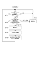
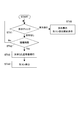
- FIG. 5 is a flowchart showing an example of the slump evaluation process by the mixer vehicle 100 (slump evaluation unit 111).
- the CPU 110 of the mixer truck 100 determines whether or not the mixer drum 2 is being stirred and rotated during the transportation of the ready-mixed concrete (step 11).
- the agitation rotation of the mixer drum 2 is determined based on at least one signal such as the rotation direction and rotation speed from the hydraulic motor 6 and the output (load pressure signal) of the pressure sensor 4a.
- the transportation of the ready-mixed containers refers to the period from the departure from the ready-mixed factory to the discharge or the return to the ready-mixed factory.
- the cases where the mixer drum 2 is determined not to be stirring and rotating are as follows: during mixing of raw food (high-speed rotation mode), during discharge of raw food (reverse rotation mode), during washing of the mixer drum (cleaning processing mode), after discharge of raw food On the way home of a mixer car.
- the slump evaluation unit 111 determines whether or not the change amount ( ⁇ P) of the driving pressure of the mixer drum 2 is greater than a predetermined (negative) threshold ( ⁇ Pth) based on the output of the pressure sensor 4a. If the value of ⁇ P is larger than the threshold value ( ⁇ P> ⁇ Pth), it is determined that the change in the slump of the raw control is normal and it is determined that “no water” (steps 12 and 13).
- the driving pressure of the mixer drum 2 gradually increases as the slump of the raw control unit decreases. Since ⁇ P is a value obtained by subtracting the drive pressure before the predetermined first time (T1) from the current drive pressure, it is typically a positive value (drive pressure increase). Therefore, typically, since the value of ⁇ P is larger than the threshold value ( ⁇ P> ⁇ Pth), it is determined that there is no water addition (step 13).
- the driving pressure before the first time (T1) is typically pressure data acquired in the previous cycle, but is not limited to this, and is pressure data acquired several cycles before. Also good.
- the slump evaluation unit 111 determines that ⁇ P> ⁇ Pth because it has not acquired the driving pressure data for a predetermined time (step 13).
- the slump evaluation unit 111 evaluates that the change in the slump of the raw control is abnormal and determines that “there is water” (step 14).
- the case where the value of ⁇ P is equal to or less than the threshold value means that the change in the driving pressure changes in the minus direction, that is, the driving pressure becomes lower (decreases) by a predetermined value or more.
- the driving pressure of the mixer drum 2 temporarily decreases.
- ⁇ P becomes a value equal to or less than the above threshold value. Therefore, the slump evaluation unit 111 determines that “there is water” when evaluating ⁇ P ⁇ ⁇ Pth (step 14). Then, the event is reported to the management server of the ready-mix factory (plant) via the communication unit 21 (step S15).
- the slump evaluation unit 111 stores the driving pressure data in the EEPROM 120 continuously for a predetermined second time (T2) from the time when it is determined that “there is water” (step S16).
- T2 a predetermined second time
- the second time (T2) may be set to a time necessary to increase the certainty of determination of “with water”.
- the slump evaluation unit 111 corrects the determination of “with water” to the determination of “without water” when ⁇ P ⁇ ⁇ Pth changes to ⁇ P> ⁇ Pth within the second time (T2). It may be configured to. As a result, it is possible to prevent an erroneous determination of the slump evaluation due to a temporary and rapid pressure fluctuation and to perform a highly reliable slump evaluation.
- the slump evaluation unit 111 periodically performs the above processing every predetermined time, thereby monitoring the change of the slump of the raw control unit in the mixer drum 2 and appropriately managing the quality of the raw control unit.
- the slump evaluation unit 111 may execute the above process only when the determination unit 112 determines that the vehicle state of the mixer vehicle 100 is stable.
- the time change of the slump of the live control unit is estimated from the time change of the driving pressure with respect to the mixer drum 2 that stirs the live control unit, and when a predetermined abnormality is detected in the time change of the slump, there is an addition operation to the live control unit. It is considered to be. Since the driving pressure of the mixer drum 2 is a relatively stable value even during the conveyance of the raw concrete (during the traveling of the mixer vehicle 100), it is not easily affected by the traveling vibration. For this reason, compared with the conventional method which determines the presence or absence of hydration operation with the load of the mixer vehicle 100, it becomes possible to grasp
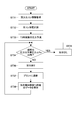
- FIG. 6 is a flowchart showing another example of the slump evaluation process by the mixer vehicle 100 (slump evaluation unit 111).
- the CPU 110 of the mixer truck 100 determines whether or not the mixer drum 2 is stirring and rotating while transporting raw concrete (step 21).
- the slump evaluation unit 111 determines whether or not the change amount ( ⁇ P) of the driving pressure of the mixer drum 2 is larger than a predetermined threshold ( ⁇ Pth) based on the output of the pressure sensor 4a (step 22). Is larger than the threshold value ( ⁇ P> ⁇ Pth), it is evaluated that the change in the slump of the raw control is normal, and it is determined that “no water” (step 23).
- the slump evaluation unit 111 determines the slump of the raw control unit based on the raw control unit temperature signal received from the temperature sensor 2a. Evaluate changes. Specifically, the slump evaluation unit 111 determines whether or not the raw kon temperature acquired this time is lower than the raw kon temperature acquired before the first time (T1), and the raw kon temperature is lower. In the case, it is determined that the change in the slump of the raw kon is abnormal, and it is determined that “there is water” (step 25).
- the slump evaluation unit 111 evaluates ⁇ P ⁇ ⁇ Pth
- the event is reported to the management server of the ready-mix factory (plant) via the communication unit 21 as in the above-described processing example 1 (step S26).
- the drive pressure data is stored in the EEPROM 120 for a predetermined second time (T2) from the time when it is determined that “there is water” (step S27).
- FIG. 7 is a flowchart illustrating another example of the slump evaluation process performed by the mixer vehicle 100 (slump evaluation unit 111).
- the slump evaluation unit 111 acquires the mixing ratio (raw kon information) of the raw materials constituting the raw kon stored in the EEPROM 120 (step 31), and based on the output of the temperature sensor 2a, The raw temperature is measured (step 32), and the driving pressure of the mixer drum 2 after a predetermined time is predicted (step 33).
- the raw cooking unit information is stored in the EEPROM 120 by the raw cooking plant factory or the driver before, during or after feeding the raw cooking unit to the mixer drum 2.
- the driving pressure after the predetermined time is assumed to be a time change of the estimated driving pressure (estimated driving force) of the mixer drum 2 from when the raw food container is introduced until the mixer vehicle 100 arrives at the placement site.
- the estimated driving force is calculated by the slump evaluation unit 111 based on the raw control unit information and the raw control unit temperature information. Note that the estimated driving force can be almost predicted by the raw material mixture ratio, the raw temperature, the environmental temperature / humidity, and the like, and may be stored in the EEPROM 120 simultaneously with the raw information. In this case, the slump evaluation unit 111 only has to read the estimated driving force stored in the EEPROM 120 during the slump evaluation of the live control.
- the slump evaluation unit 111 calculates the current driving pressure (actual driving pressure) acquired based on the output of the pressure sensor 4a every predetermined time and the current estimated driving pressure acquired from the estimated driving pressure data. And measure the difference. Then, the slump evaluation unit 111 evaluates whether or not the difference is within a predetermined range ( ⁇ Pw) (step 34), and when the difference is within the range of ⁇ Pw, the slump changes over time. It is determined that it is normal (no hydration) (step 35), and when the difference is not within the range of ⁇ Pw, it is determined that the time change of the slump is abnormal (with hydration) (step 36).
- ⁇ Pw predetermined range
- the slump evaluation unit 111 determines that the time change of the slump is abnormal, the slump evaluation unit 111 reports the event to the management server of the ready-mixed plant (plant) via the communication unit 21 as in the above-described processing example 1 ( In step S37), the driving pressure data is stored in the EEPROM 120 continuously for a predetermined second time (T2) from the time determined to be abnormal (step S38).
- FIG. 8 is a flowchart illustrating an example of a process for issuing a quality certificate for a live control issued by the issuing device 50.
- the above-described processing examples 1 to 3 in the slump evaluation unit 111 check whether water is added to the raw kon until it reaches the placement site from the raw kon factory (steps 41 and 42). Whether or not the mixer vehicle 100 has arrived at the placement site is determined by the controller 10 using, for example, a GPS device installed in the mixer vehicle 100.
- a certificate for proving that is issued by the issuing device 50 (step 43).
- the certificate is a document that describes the evaluation result regarding the time change of the slump of the live control, and the format and contents are not particularly limited.
- the raw concrete is discharged from the mixer drum 2 (step 44).
- the controller 10 displays the adding operation on the LCD 22 or the like of the mixer vehicle 100 and gives a predetermined value to the driver or the like. A warning is issued and, if necessary, a discharge prohibition command that disables the discharge operation of the raw concrete from the mixer drum 2 is output (step 45).
- the controller 10 may issue a certificate that proves that the illegal operation of the live control unit has been performed from the issuing device 50 as necessary. Further, the issuing device 50 may output the certificate as electronic data with an electronic seal or simply display it on a monitor such as the LCD 22.
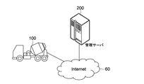
- FIG. 9 is a diagram showing an overview of a mixer vehicle management system according to an embodiment of the present invention. This embodiment is different from the first embodiment in that the management server evaluates the time variation of the slump of the live control.
- the present system includes a mixer vehicle 100 and a management server 200. Since the mixer vehicle 100 is configured in the same manner as the first embodiment described with reference to FIGS. 1 and 2, detailed description thereof is omitted here.
- the mixer vehicle 100 can communicate with the management server 200 via, for example, a radio base station (not shown) and the Internet 60.
- various status signals regarding the mixer vehicle 100 such as an engine speed signal, a load pressure signal of the drive device 4, and a temperature signal of the raw control unit acquired by the controller 10 are transmitted at predetermined intervals via the communication unit 21. It is configured to transmit to the management server 200.
- the management server 200 is a server that is operated by, for example, a manufacturing factory (plant) of a ready-mixed container transported by the mixer truck 100, and is capable of communicating with the mixer truck 100 via the Internet 60. Further, another user server operated by the manufacturer or rental company of the mixer truck 100 may be connected to the mixer truck 100 or the management server 200 via the Internet 60 so as to be communicable.
- the management server 200 is installed to manage the quality of the live concrete carried by the mixer truck 100, issue a certificate certifying the quality as needed, or notify the quality abnormality.
- the present system may be used for managing the operation status, maintenance time, etc. of the mixer truck 100.
- FIG. 10 is a block diagram showing a hardware configuration of the management server 200.
- the management server 200 includes a CPU 210 (server control unit), a ROM 220, a RAM 230, a communication unit 240 (server communication unit), a storage unit 250, and a timer 260.
- the CPU 210 appropriately accesses the EEPROM 120, the RAM 130, and the like as necessary, and performs overall control of each block of the management server 200 while performing various arithmetic processes.
- the ROM 220 is a non-volatile memory in which firmware such as an OS, a program, and various parameters to be executed by the CPU 210 is fixedly stored.
- the RAM 230 is used as a work area of the CPU 210 and temporarily holds the OS, various applications being executed, and various data being processed.
- the communication unit 240 is, for example, an NIC (Network Interface Card) for Ethernet, and performs communication processing with the mixer vehicle 100.
- NIC Network Interface Card
- the storage unit 250 is a non-volatile memory such as an HDD (Hard Disk Drive), a flash memory (SSD; Solid State Drive), or other solid-state memory.
- the storage unit 250 stores various applications and various data.
- the storage unit 250 also stores a program for executing the slump evaluation process of the live control in the slump evaluation unit 211.
- the timer 260 is used to start and end various operations of the management server 200.
- the CPU 210 has a slump evaluation unit 211.
- the slump evaluation unit 211 is configured to acquire the output of the pressure sensor 4a from the mixer vehicle 100 at predetermined time intervals and evaluate the fluidity of the raw cooking medium in the mixer drum 2. Specifically, it is configured to evaluate the time change of the slump of the live control by executing the same processing as the slump evaluation unit 111 described in the first embodiment.
- FIG. 11 is a flowchart illustrating an example of the slump evaluation process for live control executed by the slump evaluation unit 211 of the management server 200.
- the slump evaluation unit 211 determines whether or not the mixer drum 2 of the mixer truck 100 that transports the raw concrete is being stirred and rotated (step 51).
- the stirring rotation of the mixer drum 2 is determined based on the output of the pressure sensor 4a transmitted from the mixer vehicle 100.
- the slump evaluation unit 211 determines that the amount of change ( ⁇ P) in the driving pressure of the mixer drum 2 is a predetermined threshold ( ⁇ ), as in the first embodiment, based on the output of the pressure sensor 4a transmitted from the mixer vehicle 100. If the value of ⁇ P is larger than the threshold value ( ⁇ P> ⁇ Pth), it is evaluated that the change in the slump of the raw control is normal, and “no water” is determined (step 52, 53). On the other hand, when the value of ⁇ P is equal to or smaller than the above threshold value ( ⁇ P ⁇ ⁇ Pth), the slump evaluation unit 211 evaluates that the change in the slump of the raw control is abnormal as in the first embodiment, and “is hydrated”. (Step 54).
- the slump evaluation unit 211 reports the event to the mixer vehicle 100 via the communication unit 240 (step S55). Then, the slump evaluation unit 211 continues to store the driving pressure data in the storage unit 250 for a predetermined second time (T2) from the time when it is determined that “there is water” (step S56). Then, if necessary, a certificate issuance command for certifying the quality of the raw control is transmitted to the mixer vehicle 100.
- the slump evaluation unit 211 periodically monitors the change in the slump of the live control in the mixer drum 2 of the mixer vehicle 100 by periodically executing the above processing every predetermined time.
- the slump evaluation procedure is not limited to the above example, and the evaluation example 2 or 3 described in the first embodiment may be employed.
- the slump evaluation of the raw concrete as described above can be performed not only on the mixer truck 100 but also on the raw concrete carried by a plurality of mixer trucks that are communicably connected to the management server 200.
- the ready-mixed ready-mixed kon is described as an example.
- the material is kneaded by kneading and rotating the mixer drum during transportation or at the setting site. You may make it monitor the time change of the fluidity
- the example in which the driving pressure or driving torque of the mixer drum is referred to the slump evaluation of the raw control unit has been described, but in addition to this, the time change of the rotation speed of the mixer drum may be referred to.
- the mixer drum rotation speed may be increased in order to knead the ready-mixed concrete, so the presence or absence of hydration should also be evaluated by detecting an unnatural increase in the drum rotation speed during transportation. Can do.
- the drive device 4 that rotates the mixer drum 2 is configured by a hydraulic circuit including the hydraulic pump 5 and the hydraulic motor 6 that are operated by the power of the engine 3, but the electric motor, or the electric motor and the hydraulic circuit.
- the driving device may be configured in combination.
Landscapes
- Engineering & Computer Science (AREA)
- Health & Medical Sciences (AREA)
- Chemical & Material Sciences (AREA)
- Life Sciences & Earth Sciences (AREA)
- Biochemistry (AREA)
- Mechanical Engineering (AREA)
- General Health & Medical Sciences (AREA)
- General Physics & Mathematics (AREA)
- Immunology (AREA)
- Pathology (AREA)
- Analytical Chemistry (AREA)
- Physics & Mathematics (AREA)
- Structural Engineering (AREA)
- Ceramic Engineering (AREA)
- Food Science & Technology (AREA)
- Medicinal Chemistry (AREA)
- Public Health (AREA)
- Transportation (AREA)
- Dispersion Chemistry (AREA)
- Preparation Of Clay, And Manufacture Of Mixtures Containing Clay Or Cement (AREA)
Abstract
Description
上記駆動装置は、上記ミキサドラムを回転させる駆動力を発生する。
上記検出部は、上記駆動力及び上記内容物の温度のうち少なくとも1つに関連する情報を検出する。
上記評価部は、上記検出部の出力に基づき、上記内容物の流動性の時間変化を評価する。
これにより、上記異常を事後的に分析することが可能となるとともに、記憶部に記憶されるデータ量の削減を図ることができる。
あるいは上記検出部は、上記ミキサドラムに取り付けられ上記内容物の温度を検出する温度センサを含んでもよい。
これにより、ミキサ車の管理システムに内容物の品質監視機能をもたせることができる。
信号待ちのときなど車両が一時停止中は、エンジン回転数や車両振動が落ち着いているため、評価部における内容物の流動性評価の信頼性が高められる。
上記評価部は、典型的には、上記ミキサドラムによる上記内容物の撹拌回転時に、上記内容物の流動性の時間変化を評価するように構成される。
上記ミキサ車は、内容物を収容するミキサドラムと、上記ミキサドラムを回転させる駆動力を発生する駆動装置と、上記駆動力及び前記内容物の温度のうち少なくとも1つに関連する情報を検出する検出部と、上記管理サーバと通信可能なミキサ車通信部と、上記検出部の出力に基づき、上記内容物の流動性の時間変化を取得可能であり、取得された上記流動性の時間変化を上記管理サーバへ送信するように上記ミキサ車通信部を制御可能なミキサ車制御部とを有する。
上記管理サーバは、上記ミキサ車と通信可能なサーバ通信部と、送信された上記流動性の時間変化を受信するように上記サーバ通信部を制御可能であり、受信された上記流動性の時間変化が正常であるか否かを判定するように構成されたサーバ制御部と、を有する。
図1は、本発明の一実施形態に係るミキサ車の平面図であり、図2は、上記ミキサ車のハードウェア構成を示すブロック図である。以下、図1及び図2を参照して、本実施形態のミキサ車100の全体構成について説明する。
ミキサ車100は、モルタルやレディミクストコンクリート等の生コンクリート(生コン)を収容してそれを土木や建築の工事現場へ運搬するミキサドラム2を備える。ミキサ車100は、運転室11と、架台1と、架台1に搭載されて生コンを収容可能なミキサドラム2と、ミキサドラム2を回転駆動する駆動装置4と、ミキサ車100の各ブロックを制御するコントローラ10とを有する。
なお走行用のエンジン3以外にミキサドラム専用のエンジンが装備されてもよく、この場合は当該専用のエンジンを動力源としてミキサドラムが回転駆動される。
これ以外にも、油圧ポンプ5は、コントローラ10からの指令信号を受信してポンプの傾転角を正転方向又は逆転方向に切り換えるように構成されてもよい。この場合、油圧ポンプ5は、その傾転角を調整するための電磁弁を有する。この電磁弁が切り換えられることによって、油圧ポンプ5の吐出方向と吐出容量が調整される。
ミキサドラム2の所定回転とは、例えば、半回転や1回転などが挙げられる。例えば、ミキサドラム2の内周面に生コン撹拌用のブレードが位相差180°で一対(計2枚)設けられている場合、少なくとも半回転分の圧力センサ4aの出力の平均値によって生コンの流動性を評価することで、安定的な結果を得ることができる。ブレードの誤差を考慮すれば、少なくとも1回転分の平均値を用いることで検出精度がより向上する。なお、ミキサドラム2の半回転又は1回転の判断は、回転センサ9aの出力等を用いてコントローラ10において実行可能である。
この場合、スランプ評価部111は、ミキサドラム2の回転開始からタイマを起動し、所定時間(例えば数秒~数分)毎に温度センサ2aから受信される温度信号をEEPROM120又はRAM130に記憶し、当該温度信号に基づいてミキサドラム2内の生コン温度の変化を監視する。そしてスランプ評価部111は、ミキサドラム2内の生コン温度の時間変化(例えば変化率)又はその変化量に基づいて、ミキサドラム2内の生コンの流動性(スランプ)の時間変化を評価する。より具体的に、スランプ評価部111は、温度センサ2aの出力の変化量又は増加量が所定値より大きいときは、スランプの時間変化が正常であると判定し、温度センサ2aの出力の変化量又は増加量が上記所定値以下のときは、スランプの時間変化が異常であると判定するように構成される。得られた評価結果は、例えばEEPROM120又はRAM130に記憶(保存)される。
また、車両状態が安定しているときの圧力センサ4aや温度センサ2aの出力を取得、蓄積することで、生コンの流動性変化の傾向の推定が可能となり、さらに生コンの品質向上に寄与し得るデータベースの構築が可能となる。
なお、生コンの材料をミキサドラム2内に投入可能な投入モードに切り換える投入モードスイッチや、ミキサドラム2内の生コンを排出可能な排出モードに切り換える排出モードスイッチ、ミキサドラム2内の生コンを所定時間だけ混練する混練スイッチ等が設けられてもよい。
次に、以上のように構成されるミキサ車100の典型的な動作について説明する。以降の説明においては、ミキサ車100のCPU110を主な動作主体として説明するが、その動作は、CPU110の制御下において実行されるプログラムとも協働して行われる。
図5は、ミキサ車100(スランプ評価部111)によるスランプ評価処理の一例を示すフローチャートである。
ここで、生コンの運搬中とは、本実施形態では、生コン工場を出発してから排出するまで、もしくは生コン工場へ帰還するまでの間をいう。また、ミキサドラム2が撹拌回転中でないと判断されるケースとしては、生コンの混練中(高速回転モード)、生コンの排出中(逆回転モード)、ミキサドラムの洗浄中(洗浄処理モード)、生コン排出後のミキサ車の帰路途上等が挙げられる。
なお、上記第1の時間(T1)前の駆動圧力は、典型的には、前回のサイクルで取得した圧力データが用いられるが、これに限られず、数サイクル前に取得した圧力データであってもよい。また、スランプ評価部111は、最初にΔPの値を評価するときは、所定時間前の駆動圧力のデータを取得していないため、ΔP>-Pthと判定する(ステップ13)。
図6は、ミキサ車100(スランプ評価部111)によるスランプ評価処理の他の例を示すフローチャートである。
図7は、ミキサ車100(スランプ評価部111)によるスランプ評価処理の他の例を示すフローチャートである。
図8は、発行装置50において発行される生コンの品質証明書の発行処理の一例を示すフローチャートである。
[システムの概要]
図9は、本発明の一実施形態に係るミキサ車管理システムの概要を示す図である。本実施形態では、生コンのスランプの時間変化の評価を管理サーバで行う点で、第1の実施形態と異なる。
図10は、上記管理サーバ200のハードウェア構成を示したブロック図である。
図11は、管理サーバ200のスランプ評価部211が実行する生コンのスランプ評価処理の一例を示すフローチャートである。
Claims (14)
- 内容物を収容するミキサドラムと、
前記ミキサドラムを回転させる駆動力を発生する駆動装置と、
前記駆動力及び前記内容物の温度のうち少なくとも1つに関連する情報を検出する検出部と、
前記検出部の出力に基づき、前記内容物の流動性の時間変化を評価する評価部と
を具備するミキサ車。 - 請求項1に記載のミキサ車であって、
前記評価部は、前記検出部の出力の時間変化に基づき、前記内容物の流動性の時間変化を評価するように構成される
ミキサ車。 - 請求項2に記載のミキサ車であって、
前記評価部は、
前記検出部の出力の増加量が所定値より大きいときは、前記内容物の流動性の時間変化が正常であると判定し、
前記検出部の出力の増加量が前記所定値以下のときは、前記内容物の流動性の時間変化が異常であると判定するように構成される
ミキサ車。 - 請求項1~3のいずれか1つに記載のミキサ車であって、
前記評価部は、
前記駆動力の変化量が所定値より大きいときは、前記内容物の流動性の時間変化が正常であると判定し、
前記駆動力の変化量が前記所定値以下のときは、前記内容物の温度が低下したときに限って、前記内容物の流動性の時間変化が異常であると判定するように構成される
ミキサ車。 - 請求項1に記載のミキサ車であって、
前記内容物を構成する原料の配合比を記憶する第1の記憶部をさらに具備し、
前記評価部は、
前記原料の配合比に基づいて所定時間後の少なくとも前記ミキサドラムの駆動力又は前記内容物の温度の推定値のいずれか一方を算出し、
前記検出部の出力と前記推定値との差分が所定の範囲内にあるときは、前記内容物の流動性の時間変化が正常であると判定し、
前記検出部の出力と前記推定値との差分が前記所定の範囲内にないときは、前記内容物の流動性の時間変化が異常であると判定するように構成される
ミキサ車。 - 請求項1~5のいずれか1つに記載のミキサ車であって、
前記評価部は、前記ミキサドラムによる前記内容物の撹拌回転時に、前記内容物の流動性の時間変化を評価する
ミキサ車。 - 請求項1~6のいずれか1つに記載のミキサ車であって、
前記評価部による評価結果を記憶可能な第2の記憶部をさらに具備し、
前記評価部は、前記内容物の流動性の時間変化が異常であると判定した場合、当該異常と判定された時刻を含むその前後の所定時間にわたる当該流動性に関する情報を前記第2の記憶部へ記憶するように構成される
ミキサ車。 - 請求項1~7のいずれか1つに記載のミキサ車であって、
前記評価部による前記内容物の流動性の時間変化の評価結果を記載した書面を発行する発行装置をさらに具備する
ミキサ車。 - 請求項1~8のいずれか1つに記載のミキサ車であって、
前記検出部は、前記ミキサドラムの駆動圧力を検出する圧力センサ又は前記ミキサドラムの駆動トルクを検出するトルクセンサを含む
ミキサ車。 - 請求項1~9のいずれか1つに記載のミキサ車であって、
前記検出部は、前記ミキサドラムに取り付けられ前記内容物の温度を検出する温度センサを含む
ミキサ車。 - 請求項1~10のいずれか1つに記載のミキサ車であって、
管理サーバと通信することが可能な通信部をさらに具備し、
前記評価部は、前記内容物の流動性の時間変化が異常であると評価したとき、その評価結果を前記管理サーバへ送信するように前記通信部を制御するように構成される
ミキサ車。 - 請求項1~11のいずれか1つに記載のミキサ車であって、
前記内容物は、モルタル又はレディミクスコンクリートである
ミキサ車。 - 請求項1~12のいずれか1つに記載のミキサ車であって、
車両状態を判定する判定部をさらに具備し、
前記評価部は、前記判定部において車両状態が安定していると判定されたとき、前記検出部の出力に基づく前記内容物の流動性の評価を実行する
ミキサ車。 - ミキサ車と管理サーバとを具備するミキサ車管理システムであって、
前記ミキサ車は、
内容物を収容するミキサドラムと、
前記ミキサドラムを回転させる駆動力を発生する駆動装置と、
前記駆動力及び前記内容物の温度のうち少なくとも1つに関連する情報を検出する検出部と、
前記管理サーバと通信可能なミキサ車通信部と、
前記検出部の出力に基づき、前記内容物の流動性の時間変化を取得可能であり、取得された前記流動性の時間変化を前記管理サーバへ送信するように前記ミキサ車通信部を制御可能なミキサ車制御部と、を有し、
前記管理サーバは、
前記ミキサ車と通信可能なサーバ通信部と、
送信された前記流動性の時間変化を受信するように前記サーバ通信部を制御可能であり、受信された前記流動性の時間変化が正常であるか否かを判定するように構成されたサーバ制御部と、を有する
ミキサ車管理システム。
Priority Applications (1)
| Application Number | Priority Date | Filing Date | Title |
|---|---|---|---|
| AU2017249832A AU2017249832A1 (en) | 2016-04-15 | 2017-04-12 | Mixer vehicle and mixer vehicle management system |
Applications Claiming Priority (2)
| Application Number | Priority Date | Filing Date | Title |
|---|---|---|---|
| JP2016-082339 | 2016-04-15 | ||
| JP2016082339A JP2017189966A (ja) | 2016-04-15 | 2016-04-15 | ミキサ車及びミキサ車管理システム |
Publications (1)
| Publication Number | Publication Date |
|---|---|
| WO2017179626A1 true WO2017179626A1 (ja) | 2017-10-19 |
Family
ID=60042815
Family Applications (1)
| Application Number | Title | Priority Date | Filing Date |
|---|---|---|---|
| PCT/JP2017/015003 Ceased WO2017179626A1 (ja) | 2016-04-15 | 2017-04-12 | ミキサ車及びミキサ車管理システム |
Country Status (3)
| Country | Link |
|---|---|
| JP (1) | JP2017189966A (ja) |
| AU (1) | AU2017249832A1 (ja) |
| WO (1) | WO2017179626A1 (ja) |
Families Citing this family (5)
| Publication number | Priority date | Publication date | Assignee | Title |
|---|---|---|---|---|
| JP2020059159A (ja) * | 2018-10-05 | 2020-04-16 | Kyb株式会社 | スランプ値推定システム及びこれを備えたミキサ車 |
| JP7153619B2 (ja) * | 2019-07-30 | 2022-10-14 | 大成建設株式会社 | コンクリートのスランプ特定方法及びスランプ特定システム |
| JP7690267B2 (ja) * | 2020-07-29 | 2025-06-10 | カヤバ株式会社 | 表示装置 |
| JP2023538368A (ja) * | 2020-08-17 | 2023-09-07 | シドラ コーポレイト サービシズ リミティド ライアビリティ カンパニー | 生コンクリート・トラックにおける含水量及び水-セメント比のリアルタイム監視 |
| CN113752388A (zh) * | 2021-08-02 | 2021-12-07 | 潍柴动力股份有限公司 | 搅拌车的控制方法及搅拌车 |
Citations (7)
| Publication number | Priority date | Publication date | Assignee | Title |
|---|---|---|---|---|
| JPH05318456A (ja) * | 1992-05-20 | 1993-12-03 | Kayaba Ind Co Ltd | コンクリートミキサ車の混練状態表示装置 |
| JP2003346295A (ja) * | 2002-05-29 | 2003-12-05 | Yazaki Corp | ミキサ車管理支援システム及びこれに用いられる通信端末装置 |
| JP2006159658A (ja) * | 2004-12-08 | 2006-06-22 | Nikko Co Ltd | アジテータ車のコンクリート品質管理装置 |
| JP2008049499A (ja) * | 2006-08-22 | 2008-03-06 | Taiheiyo Cement Corp | アジテータ車および生コンクリート製造管理装置 |
| JP2011063955A (ja) * | 2009-09-15 | 2011-03-31 | Seiko Epson Corp | 管理方法、通信装置および運搬装置 |
| JP2013022960A (ja) * | 2011-07-19 | 2013-02-04 | Kyb Co Ltd | ミキサ車 |
| JP2013052566A (ja) * | 2011-09-02 | 2013-03-21 | Kyb Co Ltd | ミキサ車 |
Family Cites Families (1)
| Publication number | Priority date | Publication date | Assignee | Title |
|---|---|---|---|---|
| CA2853438C (en) * | 2012-11-09 | 2015-03-17 | I.B.B. Rheologie Inc. | Methods and systems using concrete mix temperature measurement |
-
2016
- 2016-04-15 JP JP2016082339A patent/JP2017189966A/ja active Pending
-
2017
- 2017-04-12 WO PCT/JP2017/015003 patent/WO2017179626A1/ja not_active Ceased
- 2017-04-12 AU AU2017249832A patent/AU2017249832A1/en not_active Abandoned
Patent Citations (7)
| Publication number | Priority date | Publication date | Assignee | Title |
|---|---|---|---|---|
| JPH05318456A (ja) * | 1992-05-20 | 1993-12-03 | Kayaba Ind Co Ltd | コンクリートミキサ車の混練状態表示装置 |
| JP2003346295A (ja) * | 2002-05-29 | 2003-12-05 | Yazaki Corp | ミキサ車管理支援システム及びこれに用いられる通信端末装置 |
| JP2006159658A (ja) * | 2004-12-08 | 2006-06-22 | Nikko Co Ltd | アジテータ車のコンクリート品質管理装置 |
| JP2008049499A (ja) * | 2006-08-22 | 2008-03-06 | Taiheiyo Cement Corp | アジテータ車および生コンクリート製造管理装置 |
| JP2011063955A (ja) * | 2009-09-15 | 2011-03-31 | Seiko Epson Corp | 管理方法、通信装置および運搬装置 |
| JP2013022960A (ja) * | 2011-07-19 | 2013-02-04 | Kyb Co Ltd | ミキサ車 |
| JP2013052566A (ja) * | 2011-09-02 | 2013-03-21 | Kyb Co Ltd | ミキサ車 |
Also Published As
| Publication number | Publication date |
|---|---|
| AU2017249832A1 (en) | 2018-11-22 |
| JP2017189966A (ja) | 2017-10-19 |
Similar Documents
| Publication | Publication Date | Title |
|---|---|---|
| WO2017179626A1 (ja) | ミキサ車及びミキサ車管理システム | |
| CN101795837B (zh) | 用于计算和报告运送车中的塌落度的方法和系统 | |
| JP5656931B2 (ja) | ミキサ車 | |
| JP5593258B2 (ja) | 運搬車でスランプを計算し、報告する方法およびシステム | |
| CN103732369B (zh) | 混凝土搅拌输送车 | |
| TW200942390A (en) | Method for monitoring thixotropy in concrete mixing drum | |
| WO2015194577A1 (ja) | ミキサ車管理システム、ミキサ車管理サーバ、ミキサ車及びミキサ車管理方法 | |
| CN102581957A (zh) | 一种搅拌车的随车物料计量指示的控制方法、装置及系统 | |
| JP2018075986A (ja) | ミキサ車 | |
| JP5688208B2 (ja) | ミキサ車 | |
| WO2016068020A1 (ja) | ミキサ車 | |
| JP6697278B2 (ja) | 運行管理装置及び運行管理方法 | |
| WO2015194578A1 (ja) | ミキサ車管理システム、ミキサ車管理サーバ、ミキサ車及びミキサ車管理方法 | |
| US12546761B2 (en) | Building material apparatus and use of at least one part sensor | |
| CN115979674A (zh) | 一种商砼车状态检测系统及方法 | |
| JP2024162910A (ja) | ミキサドラムの制御装置 | |
| JP2024162909A (ja) | ミキサドラムの制御装置 | |
| HK40001794A (en) | Wide speed range concrete monitoring calibration | |
| HK40001794B (en) | Wide speed range concrete monitoring calibration |
Legal Events
| Date | Code | Title | Description |
|---|---|---|---|
| NENP | Non-entry into the national phase |
Ref country code: DE |
|
| ENP | Entry into the national phase |
Ref document number: 2017249832 Country of ref document: AU Date of ref document: 20170412 Kind code of ref document: A |
|
| 121 | Ep: the epo has been informed by wipo that ep was designated in this application |
Ref document number: 17782439 Country of ref document: EP Kind code of ref document: A1 |
|
| 122 | Ep: pct application non-entry in european phase |
Ref document number: 17782439 Country of ref document: EP Kind code of ref document: A1 |