WO2017179366A1 - コネクタ - Google Patents
コネクタ Download PDFInfo
- Publication number
- WO2017179366A1 WO2017179366A1 PCT/JP2017/011101 JP2017011101W WO2017179366A1 WO 2017179366 A1 WO2017179366 A1 WO 2017179366A1 JP 2017011101 W JP2017011101 W JP 2017011101W WO 2017179366 A1 WO2017179366 A1 WO 2017179366A1
- Authority
- WO
- WIPO (PCT)
- Prior art keywords
- electric wire
- rubber plug
- terminal
- connector
- cavity
- Prior art date
- Legal status (The legal status is an assumption and is not a legal conclusion. Google has not performed a legal analysis and makes no representation as to the accuracy of the status listed.)
- Ceased
Links
Images


Classifications
-
- H—ELECTRICITY
- H01—ELECTRIC ELEMENTS
- H01R—ELECTRICALLY-CONDUCTIVE CONNECTIONS; STRUCTURAL ASSOCIATIONS OF A PLURALITY OF MUTUALLY-INSULATED ELECTRICAL CONNECTING ELEMENTS; COUPLING DEVICES; CURRENT COLLECTORS
- H01R13/00—Details of coupling devices of the kinds covered by groups H01R12/70 or H01R24/00 - H01R33/00
- H01R13/46—Bases; Cases
- H01R13/533—Bases, cases made for use in extreme conditions, e.g. high temperature, radiation, vibration, corrosive environment, pressure
-
- H—ELECTRICITY
- H01—ELECTRIC ELEMENTS
- H01R—ELECTRICALLY-CONDUCTIVE CONNECTIONS; STRUCTURAL ASSOCIATIONS OF A PLURALITY OF MUTUALLY-INSULATED ELECTRICAL CONNECTING ELEMENTS; COUPLING DEVICES; CURRENT COLLECTORS
- H01R13/00—Details of coupling devices of the kinds covered by groups H01R12/70 or H01R24/00 - H01R33/00
- H01R13/46—Bases; Cases
- H01R13/52—Dustproof, splashproof, drip-proof, waterproof, or flameproof cases
- H01R13/5205—Sealing means between cable and housing, e.g. grommet
-
- H—ELECTRICITY
- H01—ELECTRIC ELEMENTS
- H01R—ELECTRICALLY-CONDUCTIVE CONNECTIONS; STRUCTURAL ASSOCIATIONS OF A PLURALITY OF MUTUALLY-INSULATED ELECTRICAL CONNECTING ELEMENTS; COUPLING DEVICES; CURRENT COLLECTORS
- H01R33/00—Coupling devices specially adapted for supporting apparatus and having one part acting as a holder providing support and electrical connection via a counterpart which is structurally associated with the apparatus, e.g. lamp holders; Separate parts thereof
- H01R33/975—Holders with resilient means for protecting apparatus against vibrations or shocks
-
- H—ELECTRICITY
- H01—ELECTRIC ELEMENTS
- H01R—ELECTRICALLY-CONDUCTIVE CONNECTIONS; STRUCTURAL ASSOCIATIONS OF A PLURALITY OF MUTUALLY-INSULATED ELECTRICAL CONNECTING ELEMENTS; COUPLING DEVICES; CURRENT COLLECTORS
- H01R2201/00—Connectors or connections adapted for particular applications
- H01R2201/26—Connectors or connections adapted for particular applications for vehicles
Definitions
- the present invention relates to a connector.
- a connector containing a terminal to be connected to the counterpart terminal is used.
- a connector described in Japanese Patent Laid-Open No. 8-96878 is known as this type of connector.
- an elastic body such as rubber packing is attached to the front end of the front holder provided on the mating side of the female housing, thereby preventing rattling that occurs when the male housing and the female housing are mated. Yes.
- a terminal is accommodated in the housing of this connector, and the terminal and the electric wire are connected.
- the terminal and the electric wire are fixed by a wire barrel that is crimped so as to be wound around the outer periphery of the core wire exposed from the end of the electric wire, and an insulation barrel that is crimped so as to be wound around the insulating coating coated on the core wire. ing.
- the vibration of the vehicle may be transmitted to the electric wire, and the vibration may be transmitted from the electric wire to the terminal accommodated in the connector.
- the terminal and the counterpart terminal slide.
- the contact portion between the terminal and the counterpart terminal is worn, and the electrical connection reliability of the terminal may be reduced.
- the connector disclosed in the present specification includes a connector housing having a cavity, a terminal housed in the cavity and provided with a wire connecting portion, an electric wire connected to the wire connecting portion of the terminal, A rubber plug that is externally fitted to the electric wire and is in close contact with the inner wall of the cavity; and a fixing portion that fixes the electric wire and the rubber plug; and the electric wire is connected to the electric wire connecting portion; A vibration absorbing portion having flexibility is provided between the portion fixed by the fixing portion.
- the electric wire and the rubber plug are fixed by the fixing portion, and the rubber plug is in close contact with the inner wall of the cavity, the electric wire is fixed to the connector housing via the rubber plug. It has become. Thereby, even when vibration is transmitted from the vehicle to the electric wire, the vibration of the electric wire can be suppressed by the connector housing.
- the electric wire is provided with a vibration absorbing portion between a portion fixed by the fixing portion and a portion connected to the electric wire connecting portion. Since the vibration is absorbed by the bending and deformation of the vibration absorbing portion, it is possible to further suppress the vibration from reaching the electric wire connecting portion.
- the electric wire is suppressed in vibration by a so-called rigid structure, and in the vibration absorbing portion, the vibration is absorbed by a so-called flexible structure.
- the electrical connection reliability of a terminal can be improved.
- the electric wire may include a flexible core wire and an insulating coating that covers the core wire, and the vibration absorbing portion may be configured by the core wire exposed from an end portion of the insulating coating.
- the connector housing may be configured to include a retaining member that comes into contact with the rubber plug fitted on the electric wire from a direction in which the electric wire is led out from the connector housing.
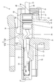
- the connector C of the present embodiment includes a connector housing 10, a terminal 50 connected to the electric wire 30, a rubber plug 60 that fits outside the electric wire 30, and the electric wire 30 and the rubber plug 60. And a retaining member 80 for retaining the rubber plug 60.
- the vertical direction is based on the vertical direction in FIG. Further, the left side in FIG. 2 (the fitting direction with the mating connector) is the front side, and the right side in FIG. 2 (the side from which the electric wire 30 is drawn) is the rear side.
- the connector housing 10 is made of synthetic resin, and as shown in FIG. 2, a plurality of cavities 11 in which a part of the terminals 50 and the electric wires 30 are accommodated are provided in the left-right direction.
- Each cavity 11 extends in the front-rear direction, the first half portion is a terminal accommodating portion 11A that accommodates the terminal 50, and the second half portion is the end portion of the electric wire 30 and the wire accommodating portion 11B that accommodates the rubber plug 60.
- the inner dimension of the wire accommodating part 11 ⁇ / b> B is larger than the inner dimension of the terminal accommodating part 11 ⁇ / b> A.
- the terminal accommodating portion 11A of the cavity 11 has a rectangular shape in the rear view, while the electric wire accommodating portion 11B has a circular shape in the rear view.
- a cantilever lance 13 is provided on the bottom wall of the terminal accommodating portion 11 ⁇ / b> A of the cavity 11.
- the lance 13 can be elastically deformed in the vertical direction and can lock the terminal 50.
- An insertion port 15 through which the mating terminal can be inserted is provided in front of the cavity 11, and an opening 17 through which the electric wire 30 can be led out is provided behind the cavity 11.
- the electric wire 30 has a configuration in which a flexible core wire 31 made of a plurality of metal wires is covered with an insulating coating 33.
- the core wire 31 is flexible enough to bend in a direction crossing the axial direction, and the periphery is covered with an insulating coating 33.
- the terminal 50 is formed by pressing and then bending a conductive metal plate material.
- the terminal 50 includes a rectangular tube-shaped connecting portion 51 connected to the mating terminal, and a wire connecting portion 53 connected to the core wire 31 of the electric wire 30 provided in the rear of the connecting portion 51.
- the electric wire connecting portion 53 includes an open barrel type caulking piece, and the caulking piece is caulked and crimped so as to wrap around the outer periphery of the core wire 31, whereby the core wire 31 and the terminal 50 are connected.
- the connecting portion 51 is locked in the cavity 11 by the lance 13.
- the rubber plug 60 has a long cylindrical shape in the front-rear direction and is externally fitted to the electric wire 30. Specifically, the electric wire 30 is externally fitted to a portion provided with the insulating coating 33.
- the central axis of the rubber plug 60 is arranged coaxially with the terminal 50 (connecting portion 51).
- the rubber plug 60 includes a rubber plug main body 61 and a rubber plug fixing portion 63 that is connected to the front of the rubber plug main body 61 and is fixed by a fixing portion 70.
- the outer diameter size of the rubber plug fixing portion 63 fixed by the fixing portion 70 is smaller than the outer diameter size of the rubber plug main body portion 61.
- An outer peripheral lip 65 that elastically adheres to the inner peripheral wall of the wire accommodating portion 11B of the cavity 11 is provided on the outer peripheral surface of the rubber plug main body 61 in a protruding manner.
- the outer peripheral lip 65 is formed over the entire periphery in a sectional uneven shape.
- the rear end portion of the rubber plug main body 61 is a large-diameter portion 67 that is tightly fitted to the rear end portion of the electric wire housing portion 11B.
- the large-diameter portion 67 is tightly fitted to the electric wire housing portion 11B behind the outer peripheral lip 65, so that even if the electric wire 30 led out from the rubber plug 60 is bent, the electric wire housing portion 11B A gap is prevented from being formed between the inner peripheral wall and the outer peripheral lip 65.
- the fixing part 70 is made of metal and is an open barrel-shaped plate member.
- the rubber plug 60 and the electric wire 30 are fixed by caulking (crimping) the fixing portion 70 so as to be wound around the outer periphery of the rubber plug fixing portion 63 of the rubber plug 60.
- the retaining member 80 is made of a synthetic resin, and covers the rear surface of the connector housing 10 and the opening 17 as shown in FIGS. 1 and 2. Further, the retaining member 80 is mounted so as to come into contact with the rubber plug 60 from the direction in which the electric wire 30 is led out from the connector housing 10 (backward).
- the retaining member 80 includes a plate-shaped retaining main body 81 and a locking portion 83 for locking to the connector housing 10.
- the retaining main body 81 has a rectangular shape in rear view, and the rear surface of the rubber stopper 60 and the front surface of the retaining main body 81 are in contact with each other, thereby restricting the rubber stopper 60 from moving backward.
- the retaining main body 81 is provided with an insertion groove 85 for inserting the electric wire 30.
- the insertion groove 85 is provided by being cut out in a groove shape from the upper edge of the retaining main body 81 to the center position in the vertical direction.
- the inner dimension of the insertion groove 85 in the width direction is the same as or slightly smaller than the outer diameter of the electric wire 30.
- a total of four locking portions 83 are provided, one each from the upper and lower edges of the retaining main body 81.
- the locking portion 83 extends forward from the upper edge and the lower edge of the retaining main body portion 81, and a locking claw 83A that protrudes toward the connector housing 10 is provided at the tip of the locking portion 83.
- the locking claw 83 ⁇ / b> A is locked in a locking recess 19 provided in the connector housing 10.
- the locking recess 19 is provided at the rear end of the connector housing 10 and is recessed inside the connector housing 10 in accordance with the shape of the locking claw 83A.
- the insulation coating 33 from the position where the terminal 50 is connected to the position where the rubber plug 60 is externally fitted is peeled off to expose the core wire 31 to the electric wire 30.
- the vibration absorbing portion 35 having flexibility is formed. Since the vibration absorbing portion 35 is not covered with the insulating coating 33, the vibration absorbing portion 35 is more easily bent than the portion of the electric wire 30 covered with the insulating coating 33.
- the length of the vibration absorbing portion 35 in the front-rear direction is longer than the size between the position where the wire connecting portion 53 of the terminal 50 is disposed and the position where the rubber plug 60 is disposed. Therefore, when the terminal 50 and the rubber plug 60 are arranged at the normal positions, the vibration absorbing portion 35 is bent in a direction intersecting with the front-rear direction (direction in which the electric wire 30 extends).
- the connector C of the present embodiment is configured as described above, and the assembly method and operation will be described subsequently.
- the insulating coating 33 is peeled off at the end of the electric wire 30.
- the insulation coating 33 is peeled off more than usual, and the core wire 31 is exposed to a position just before the position where the rubber plug 60 is attached, thereby forming the vibration absorbing portion 35 in the electric wire 30.
- the rubber plug 60 is passed through the electric wire 30 and the rubber plug 60 is externally fitted to the electric wire 30 at a position where the front end position of the insulating coating 33 and the front end position of the rubber plug 60 are aligned. Then, the electric wire 30 and the rubber plug 60 are fixed by caulking the fixing portion 70 around the outer periphery of the rubber plug fixing portion 63. In addition, the electric wire 30 and the rubber plug 60 are firmly fixed by the fixing portion 70 so that the electric wire 30 and the rubber plug 60 do not move relatively.
- the terminal 50 is connected to the end of the exposed core wire 31 of the electric wire 30.
- the terminal 50 and the core wire 31 are crimped.
- the electric wire 30 to which the terminal 50 is attached is inserted through the retaining member 80.
- the wire 30 extending from the rear side of the rubber plug 60 is inserted into the insertion groove so that the rear end surface (rear end surface of the large diameter portion 67) of the rubber plug main body 61 of the rubber plug 60 contacts the front surface of the retaining main body portion 81.
- the electric wire 30 is pulled out to the rear of the retaining member 80 by being inserted through the wire 85.
- the terminal 50 to which the electric wire 30 is connected is accommodated in the connector housing 10.
- the terminal 50 is accommodated in the normal position of the terminal accommodating portion 11 ⁇ / b> A of the cavity 11, the terminal 50 is locked by the lance 13.
- the rubber plug main body 61 of the rubber plug 60 is positioned behind the normal position of the vibration absorbing portion 35 for the redundant amount (the length for bending). More specifically, the rubber plug main body 61 is located outside the cavity 11 of the connector housing 10, and the rubber plug main body 61 is exposed rearward from the opening 17. Further, the retaining member 80 is also located behind the normal position in accordance with the position of the rubber plug 60.
- the retaining member 80 is pushed forward, and the retaining member 80 is attached to the connector housing 10 as shown in FIG.
- the rubber plug main body portion 61 pushed by the retaining main body portion 81 is pushed into the electric wire accommodating portion 11B of the cavity 11 of the connector housing 10, and the outer peripheral lip 65 becomes the electric wire of the cavity 11. It closely contacts the inner wall of the accommodating portion 11B.
- the large diameter portion 67 is also in close contact with the inner wall of the rear end portion of the cavity 11.
- the core wire 31 (vibration absorbing portion 35) exposed from the insulating coating 33 is bent in the wire housing portion 11 ⁇ / b> B of the cavity 11. Then, the locking claw 83A of the locking portion 83 of the locking member 80 is locked to the locking recess 19 of the connector housing 10 as shown in FIG. Installed.
- the rubber plug 60 fixed by the electric wire 30 and the fixing portion 70 is in close contact with the inner wall of the electric wire housing portion 11B of the cavity 11 of the connector housing 10.
- the rubber stopper 60 is fixed so that it does not fall out of the cavity 11 when the retaining member 80 abuts from behind. Therefore, the electric wire 30 is fixed to the connector housing 10 via the rubber plug 60. Therefore, even if vibration is transmitted to the electric wire 30 from the outside, the electric wire 30 is fixed to the connector housing 10 via the rubber plug 60, so that the vibration of the electric wire 30 is suppressed.
- the electric wire 30 is provided with a vibration absorbing portion 35 between a portion fixed to the rubber plug 60 by the fixing portion 70 and a portion connected to the electric wire connecting portion 53 of the terminal 50. Since the vibration absorbing portion 35 has flexibility and the vibration is absorbed by the bending deformation, the vibration can be further suppressed from reaching the electric wire connecting portion 53.
- the connector C of the present embodiment it is possible to suppress the vibration transmitted from the outside to the electric wire 30 from reaching the terminal 50.
- vibration is suppressed by a so-called rigid structure in a portion where the rubber plug 60 is fitted (a portion where the rubber plug 60 is fixed by the fixing portion 70).
- vibration absorbing portion 35 vibration is absorbed by a so-called flexible structure. That is, the transmission of vibration is suppressed by the double structure of the rigid structure and the flexible structure.
- the vibration absorbing portion 35 is composed of the core wire 31 exposed from the end of the insulating coating 33.
- the vibration absorbing portion 35 only needs to have flexibility without peeling off the insulating coating. .
- the fixing portion 70 is fixed by winding an open barrel-shaped metal plate-like member around the outer periphery of the rubber plug 60, but it is fixed by fitting a C-ring or the like into the outer periphery. May be. Moreover, it may be fixed by mounting a fixing member between the rubber plug and the electric wire, or may be fixed between the electric wire 30 by increasing the hardness of the fixing portion by two-color molding of the rubber plug. good.
Landscapes
- Connector Housings Or Holding Contact Members (AREA)
Abstract
キャビティ11を有するコネクタハウジング10と、前記キャビティ11内に収容されると共に、電線接続部53を備えた端子50と、前記端子50の前記電線接続部53に接続された電線30と、前記電線30に外嵌されると共に前記キャビティ11の内壁に密着するゴム栓60と、前記電線30と前記ゴム栓60とを固定する固定部70と、を備え、前記電線30は、前記電線接続部53に接続された部分と、前記固定部70によって固定された部分との間に、可撓性を有する振動吸収部35を備えた。
Description
本発明は、コネクタに関する。
自動車等の車両に搭載された電気機器の接続には、相手側端子と接続される端子を収容したコネクタが用いられる。この種のコネクタとして特開平8-96878号公報に記載のものが知られている。このコネクタは、雌ハウジングの嵌合側に設けたフロントホルダの前端にゴムパッキンなどの弾性体を装着することにより、雄ハウジングと雌ハウジングとの嵌合時に生じるガタつきを防止するようになっている。
また、このコネクタのハウジング内には端子が収容され、この端子と電線が接続される。端子と電線とは、電線の端末から露出した芯線の外周に巻き付くように圧着されたワイヤーバレルと、芯線に被覆された絶縁被覆に巻き付くように圧着されたインシュレーションバレルと、によって固定されている。
しかしながら、雄ハウジングと雌ハウジングとの間のガタつきを抑制したとしても、車両の振動が電線に伝わり、この電線から、コネクタ内に収容された端子へと、振動が伝達される場合がある。この結果、端子と、相手側端子とが摺動することが懸念される。すると、端子と相手側端子との接点部に摩耗が生じて、端子の電気的な接続信頼性が低下する虞がある。
本明細書で開示されるコネクタは、キャビティを有するコネクタハウジングと、前記キャビティ内に収容されると共に、電線接続部を備えた端子と、前記端子の前記電線接続部に接続された電線と、前記電線に外嵌されると共に前記キャビティの内壁に密着するゴム栓と、前記電線と前記ゴム栓とを固定する固定部と、を備え、前記電線は、前記電線接続部に接続された部分と、前記固定部によって固定された部分との間に、可撓性を有する振動吸収部を備えた。
このような構成によると、固定部によって電線とゴム栓とが固定されており、このゴム栓がキャビティの内壁に密着しているので、電線はゴム栓を介してコネクタハウジングに固定された状態になっている。これにより、車両から電線に振動が伝達された場合でも、コネクタハウジングによって電線の振動を抑制することができる。
また、電線には、固定部によって固定された部分と、電線接続部に接続された部分との間に、振動吸収部が設けられている。この振動吸収部が撓み変形することによって振動が吸収されるので、振動が電線接続部に達することをより抑制することができる。
このように、電線は、ゴム栓が外嵌された部分においては、いわゆる剛構造によって振動が抑制され、また、振動吸収部においては、いわゆる柔構造によって振動が吸収されるようになっている。これにより、振動が端子に伝達されることが抑制されるので、端子の電気的な接続信頼性を向上させることができる。
本明細書に開示されるコネクタの実施の態様として、以下の構成としてもよい。
前記電線は、可撓性を有する芯線と、前記芯線を覆う絶縁被覆と、を備え、前記振動吸収部は、前記絶縁被覆の端部から露出した前記芯線からなる構成としても良い。
前記電線は、可撓性を有する芯線と、前記芯線を覆う絶縁被覆と、を備え、前記振動吸収部は、前記絶縁被覆の端部から露出した前記芯線からなる構成としても良い。
このような構成では、絶縁被覆から露出した芯線が振動吸収部とされているので、さらに振動を吸収することができる。これにより、端子の電気的な接続信頼性をより向上させることができる。
また、前記コネクタハウジングは、前記電線に外嵌された前記ゴム栓に、前記電線の前記コネクタハウジングからの導出方向から当接する抜け止め部材を備えた構成としても良い。
このような構成によれば、抜け止め部材によってゴム栓が固定されるため、電線の振動を一層抑制することができる。
本明細書に開示されるコネクタによれば、電線からの振動が端子に伝達することを抑制することができる。
<実施形態>
実施形態を図1及び図3の図面を参照しながら説明する。
本実施形態のコネクタCは、図1及び図2に示すように、コネクタハウジング10と、電線30に接続された端子50と、電線30に外嵌するゴム栓60と、電線30とゴム栓60とを固定する固定部70と、ゴム栓60を抜け止めする抜け止め部材80とを備えている。以下の説明では、上下方向については、図2の上下方向を基準とする。また、図2における左側(相手側コネクタとの嵌合方向)を前側とし、図2における右側(電線30が引き出される側)を後側とする。
実施形態を図1及び図3の図面を参照しながら説明する。
本実施形態のコネクタCは、図1及び図2に示すように、コネクタハウジング10と、電線30に接続された端子50と、電線30に外嵌するゴム栓60と、電線30とゴム栓60とを固定する固定部70と、ゴム栓60を抜け止めする抜け止め部材80とを備えている。以下の説明では、上下方向については、図2の上下方向を基準とする。また、図2における左側(相手側コネクタとの嵌合方向)を前側とし、図2における右側(電線30が引き出される側)を後側とする。
コネクタハウジング10は、合成樹脂製であって、図2に示すように、端子50及び電線30の一部が収容されるキャビティ11が左右方向に複数並んで設けられている。各キャビティ11は前後方向に延びており、前半部分が端子50を収容する端子収容部11Aとなっており、後半部分が電線30の端部及びゴム栓60を収容する電線収容部11Bとなっている。キャビティ11は、端子収容部11Aの内寸法よりも電線収容部11Bの内寸法が大きくなっている。キャビティ11の端子収容部11Aは後方視矩形状をしている一方で、電線収容部11Bは後方視円形状をしている。
キャビティ11の端子収容部11Aの底壁には、片持ち状のランス13が設けられている。ランス13は、上下方向に弾性変形可能で、端子50を係止可能となっている。キャビティ11の前方には、相手側端子が挿通可能な挿入口15が設けられており、キャビティ11の後方には、電線30を導出可能な開口部17が設けられている。
電線30は、図2に示すように、複数の金属素線からなる可撓性を有する芯線31が絶縁被覆33によって覆われた構成となっている。芯線31は軸線方向と交差する方向に撓み可能な程度の可撓性を有しており、周囲は絶縁被覆33に覆われている。
端子50は、導電性の金属板材をプレス加工後、折り曲げ加工して形成される。端子50は、図2に示すように、相手側端子と接続される角筒状の接続部51と、接続部51の後方に連なって設けられ電線30の芯線31と接続される電線接続部53とを備えている。電線接続部53はオープンバレル形式のかしめ片を備えており、このかしめ片が芯線31の外周に巻き付くようにかしめ付けられて圧着されることで、芯線31と端子50が接続される。接続部51はランス13によってキャビティ11内に係止されている。
ゴム栓60は、図2に示すように、前後方向に長い円筒形状をしており、電線30に外嵌されている。詳細には、電線30のうち絶縁被覆33が設けられた部分に外嵌されている。ゴム栓60の中心軸は、端子50(接続部51)と同軸上に配されている。ゴム栓60は、ゴム栓本体部61と、ゴム栓本体部61の前方に連設されて固定部70によって固定されるゴム栓固定部63とを備えている。固定部70によって固定された状態のゴム栓固定部63の外径寸法は、ゴム栓本体部61の外径寸法よりも小さくなっている。
ゴム栓本体部61の外周面には、キャビティ11の電線収容部11Bの内周壁に対して弾性的に密着する外周リップ65が突出した形態で周設されている。外周リップ65は、断面視凹凸形状をなして全周に亘って形成されている。ゴム栓60が電線収容部11B内に嵌合されると、各外周リップ65の頂点部分が電線収容部11Bの内周壁によって押し潰されて密着し、電線30の外周面と電線収容部11Bの内周壁との間がゴム栓60によってシールされる。
ゴム栓本体部61の後端部は、電線収容部11Bの後端部に緊密に嵌合する大径部67とされている。この大径部67は外周リップ65の後方において電線収容部11Bに対して緊密に嵌合することにより、ゴム栓60から後方に導出された電線30が仮に曲げられても、電線収容部11Bの内周壁と外周リップ65との間に隙間ができることを防止している。
固定部70は、金属製であって、オープンバレル形状の板状部材である。固定部70がゴム栓60のゴム栓固定部63の外周に巻き付けるようにかしめ付けられる(圧着される)ことで、ゴム栓60と電線30が固定される。
抜け止め部材80は、合成樹脂製であって、図1及び図2に示すように、コネクタハウジング10の後面及び開口部17を覆うようになっている。また、抜け止め部材80は、電線30のコネクタハウジング10からの導出方向(後方)からゴム栓60に当接するように装着されている。抜け止め部材80は、平板状の抜け止め本体部81と、コネクタハウジング10に係止するための係止部83とを備えている。抜け止め本体部81は、後面視矩形状をしており、ゴム栓60の後面と抜け止め本体部81の前面とが当接することで、ゴム栓60が後方に移動するのを規制する。また、抜け止め本体部81には、電線30を挿通するための挿通溝85が設けられている。挿通溝85は、抜け止め本体部81の上縁から上下方向の中央位置まで溝状に切欠かれることで設けられている。挿通溝85の幅方向の内寸は、電線30の外径と同じか若干小さくなっている。
係止部83は、抜け止め本体部81の上縁と下縁から各一対ずつ合計4つ設けられている。係止部83は、抜け止め本体部81の上縁と下縁から前方に向かって延びており、その先端部にコネクタハウジング10側に突出する係止爪83Aが設けられている。係止爪83Aは、コネクタハウジング10に設けられた係止凹部19に係止される。係止凹部19は、コネクタハウジング10の後端部に設けられており、係止爪83Aの形状に合わせて、コネクタハウジング10の内側に凹んでいる。係止爪83Aが係止凹部19に係止することで、抜け止め部材80がコネクタハウジング10に係止される。
さて、電線30には、図2及び図3に示すように、端子50が接続された位置からゴム栓60が外嵌される位置までの絶縁被覆33を皮剥ぎして芯線31を大きく露出させることで、可撓性を有する振動吸収部35が形成されている。振動吸収部35は、絶縁被覆33に覆われていないので、電線30のうち絶縁被覆33に覆われた部分に比べて撓み易くなっている。振動吸収部35は、その前後方向の長さ寸法が端子50の電線接続部53が配される位置とゴム栓60が配される位置との間の寸法よりも長くなっている。そのため、端子50及びゴム栓60が正規位置に配されると、振動吸収部35は前後方向(電線30が延びる方向)と交差する方向に撓んだ状態になっている。
本実施形態のコネクタCは、以上のような構成であって、続いてその組み付け方法及び作用を説明する。
まず、電線30の端部において、絶縁被覆33を皮剥ぎする。この際に、通常よりも絶縁被覆33を大きく皮剥ぎし、ゴム栓60が装着される位置の手前まで芯線31を露出させることにより、電線30に振動吸収部35を形成する。
まず、電線30の端部において、絶縁被覆33を皮剥ぎする。この際に、通常よりも絶縁被覆33を大きく皮剥ぎし、ゴム栓60が装着される位置の手前まで芯線31を露出させることにより、電線30に振動吸収部35を形成する。
次に、電線30にゴム栓60を先通しして、絶縁被覆33の前端位置とゴム栓60の前端位置が揃う位置で電線30にゴム栓60を外嵌する。そして、固定部70をゴム栓固定部63の外周に巻き付けるようにしてかしめ付けることで、電線30とゴム栓60とを固定する。なお、電線30とゴム栓60とが相対的に移動しない程度に、固定部70によって電線30とゴム栓60とは強固に固定されている。
そして、電線30の露出した芯線31の端末に端子50を接続する。端子50の電線接続部53を芯線31にかしめ付けることで、端子50と芯線31を圧着する。次に、端子50が装着された電線30を抜け止め部材80に挿通させる。ゴム栓60のゴム栓本体部61の後端面(大径部67の後端面)が、抜け止め本体部81の前面と当接するように、ゴム栓60の後方に延びる電線30を上方から挿通溝85に挿通させて、電線30を抜け止め部材80の後方に引き出す。
次に、図1及び図2に示すように、電線30が接続された端子50をコネクタハウジング10に収容する。端子50がキャビティ11の端子収容部11Aの正規位置に収容されると、ランス13によって端子50が係止される。一方で、ゴム栓60のゴム栓本体部61は、振動吸収部35の冗長分(撓ませるための長さ分)正規位置より後方に位置している。より具体的には、ゴム栓本体部61はコネクタハウジング10のキャビティ11の後方外部に位置しており、ゴム栓本体部61は開口部17より後方に露出した状態となっている。また、抜け止め部材80もゴム栓60の位置に合わせて正規位置より後方に位置している。
この状態(図2の状態)から抜け止め部材80を前方に押し込んで、図3に示すように、抜け止め部材80をコネクタハウジング10に装着する。抜け止め部材80を前方に押すと、抜け止め本体部81に押されたゴム栓本体部61がコネクタハウジング10のキャビティ11の電線収容部11B内に押し込まれて、外周リップ65がキャビティ11の電線収容部11Bの内壁と密着する。また、大径部67もキャビティ11の後端部の内壁と密着する。一方で、絶縁被覆33から露出した芯線31(振動吸収部35)がキャビティ11の電線収容部11B内で撓んだ状態となる。そして、抜け止め部材80の係止部83の係止爪83Aが、図1に示すように、コネクタハウジング10の係止凹部19に係止されることで、抜け止め部材80がコネクタハウジング10に装着される。
このようにして、電線30と固定部70によって固定されたゴム栓60がコネクタハウジング10のキャビティ11の電線収容部11Bの内壁に密着する。また、ゴム栓60は、抜け止め部材80が後方から当接することで、キャビティ11内から抜け落ちないように固定されている。そのため、電線30はゴム栓60を介してコネクタハウジング10に固定された状態になっている。そのため、外部から電線30に振動が伝達されても、コネクタハウジング10との間でゴム栓60を介して電線30が固定された状態となっていることで、電線30の振動が抑制される。
また、電線30には、固定部70によってゴム栓60と固定された部分と、端子50の電線接続部53に接続された部分との間に、振動吸収部35が設けられている。この振動吸収部35が可撓性を有しており、撓み変形することによって振動が吸収されるので、振動が電線接続部53に達することをより抑制することができる。
以上のように、本実施形態のコネクタCでは、電線30に外部から伝達された振動が端子50に到達するのを抑制することができる。電線30は、ゴム栓60が外嵌された部分(固定部70によってゴム栓60が固定された部分)においては、いわゆる剛構造によって振動が抑制される。また、振動吸収部35においては、いわゆる柔構造によって振動が吸収されるようになっている。つまり、剛構造と柔構造の二重構造によって振動が伝達することが抑制されている。このようにして、電線30の振動が端子50に伝達されることが抑制されるので、端子50の電気的な接続信頼性を向上させることができる。
<他の実施形態>
本明細書によって開示される技術は上記記述及び図面によって説明した実施形態に限定されるものではなく、例えば次のような種々の態様も含まれる。
(1)上記実施形態では、抜け止め部材80を設けていたが、抜け止め部材80がなくても良い。
本明細書によって開示される技術は上記記述及び図面によって説明した実施形態に限定されるものではなく、例えば次のような種々の態様も含まれる。
(1)上記実施形態では、抜け止め部材80を設けていたが、抜け止め部材80がなくても良い。
(2)上記実施形態では、振動吸収部35は、絶縁被覆33の端部から露出した芯線31からなっていたが、絶縁被覆を皮剥ぎしなくても可撓性を有していれば良い。また、編組線など他の可撓性を有する材料によって形成しても良い。
(3)上記実施形態では、固定部70はオープンバレル形状の金属製の板状部材をゴム栓60の外周に巻き付けるようにして固定していたが、Cリングなどを外周にはめ込むことで固定しても良い。また、ゴム栓と電線との間に固定部材を装着することで固定しても良いし、ゴム栓を二色成型にして固定部分の硬度を上げることで電線30との間を固定しても良い。
10:コネクタハウジング
11:キャビティ
11A:端子収容部
11B:電線収容部
13:ランス
19:係止凹部
30:電線
31:芯線
33:絶縁被覆
35:振動吸収部
50:端子
51:接続部
53:電線接続部
60:ゴム栓
70:固定部
80:抜け止め部材
83:係止部
C:コネクタ
11:キャビティ
11A:端子収容部
11B:電線収容部
13:ランス
19:係止凹部
30:電線
31:芯線
33:絶縁被覆
35:振動吸収部
50:端子
51:接続部
53:電線接続部
60:ゴム栓
70:固定部
80:抜け止め部材
83:係止部
C:コネクタ
Claims (3)
- キャビティを有するコネクタハウジングと、
前記キャビティ内に収容されると共に、電線接続部を備えた端子と、
前記端子の前記電線接続部に接続された電線と、
前記電線に外嵌されると共に前記キャビティの内壁に密着するゴム栓と、
前記電線と前記ゴム栓とを固定する固定部と、を備え、
前記電線は、前記電線接続部に接続された部分と、前記固定部によって固定された部分との間に、可撓性を有する振動吸収部を備えたコネクタ。 - 前記電線は、可撓性を有する芯線と、前記芯線を覆う絶縁被覆と、を備え、
前記振動吸収部は、前記絶縁被覆の端部から露出した前記芯線からなる請求項1に記載のコネクタ。 - 前記コネクタハウジングは、前記電線に外嵌された前記ゴム栓に、前記電線の前記コネクタハウジングからの導出方向から当接する抜け止め部材を備えた請求項1または請求項2に記載のコネクタ。
Priority Applications (2)
| Application Number | Priority Date | Filing Date | Title |
|---|---|---|---|
| CN201780021770.6A CN109075493B (zh) | 2016-04-11 | 2017-03-21 | 连接器 |
| US16/088,529 US20190115689A1 (en) | 2016-04-11 | 2017-03-21 | Connector |
Applications Claiming Priority (2)
| Application Number | Priority Date | Filing Date | Title |
|---|---|---|---|
| JP2016078840A JP6195137B1 (ja) | 2016-04-11 | 2016-04-11 | コネクタ |
| JP2016-078840 | 2016-04-11 |
Publications (1)
| Publication Number | Publication Date |
|---|---|
| WO2017179366A1 true WO2017179366A1 (ja) | 2017-10-19 |
Family
ID=59854860
Family Applications (1)
| Application Number | Title | Priority Date | Filing Date |
|---|---|---|---|
| PCT/JP2017/011101 Ceased WO2017179366A1 (ja) | 2016-04-11 | 2017-03-21 | コネクタ |
Country Status (4)
| Country | Link |
|---|---|
| US (1) | US20190115689A1 (ja) |
| JP (1) | JP6195137B1 (ja) |
| CN (1) | CN109075493B (ja) |
| WO (1) | WO2017179366A1 (ja) |
Cited By (1)
| Publication number | Priority date | Publication date | Assignee | Title |
|---|---|---|---|---|
| US10116085B1 (en) | 2018-05-08 | 2018-10-30 | Delphi Technologies, Inc. | Sealed connector with an extended seal sleeve and retainer |
Families Citing this family (1)
| Publication number | Priority date | Publication date | Assignee | Title |
|---|---|---|---|---|
| DE102019118044A1 (de) * | 2019-07-04 | 2021-01-07 | Dr. Ing. H.C. F. Porsche Aktiengesellschaft | Akustisch entkoppeltes Hochvoltverbindungselement zum Einsatz in einem Elektrofahrzeug |
Citations (3)
| Publication number | Priority date | Publication date | Assignee | Title |
|---|---|---|---|---|
| JP2001244019A (ja) * | 2000-02-28 | 2001-09-07 | Yazaki Corp | ジョイントコネクタ |
| JP2004342415A (ja) * | 2003-05-14 | 2004-12-02 | Sumitomo Wiring Syst Ltd | 防水コネクタ |
| JP2013232369A (ja) * | 2012-05-01 | 2013-11-14 | Yazaki Corp | 防水コネクタ |
Family Cites Families (8)
| Publication number | Priority date | Publication date | Assignee | Title |
|---|---|---|---|---|
| JP4925229B2 (ja) * | 2009-11-30 | 2012-04-25 | 日本航空電子工業株式会社 | コネクタ |
| JP2014038793A (ja) * | 2012-08-20 | 2014-02-27 | Sumitomo Wiring Syst Ltd | コネクタ |
| JP6106544B2 (ja) * | 2013-07-02 | 2017-04-05 | 矢崎総業株式会社 | 回転式コネクタ |
| WO2015063928A1 (ja) * | 2013-10-31 | 2015-05-07 | 矢崎総業株式会社 | 防水コネクタ |
| JP6065228B2 (ja) * | 2013-11-27 | 2017-01-25 | 住友電装株式会社 | コネクタ |
| US9577367B2 (en) * | 2014-04-09 | 2017-02-21 | Delphi Technologies, Inc. | Sealed connector with an extended seal sleeve and an anti-water pooling retainer |
| DE102015012326A1 (de) * | 2014-10-03 | 2016-04-07 | Sumitomo Wiring Systems, Ltd. | Verbinder und Verfahren zum Zusammenbauen desselben |
| JP6548036B2 (ja) * | 2016-01-29 | 2019-07-24 | 住友電装株式会社 | コネクタ |
-
2016
- 2016-04-11 JP JP2016078840A patent/JP6195137B1/ja not_active Expired - Fee Related
-
2017
- 2017-03-21 WO PCT/JP2017/011101 patent/WO2017179366A1/ja not_active Ceased
- 2017-03-21 CN CN201780021770.6A patent/CN109075493B/zh not_active Expired - Fee Related
- 2017-03-21 US US16/088,529 patent/US20190115689A1/en not_active Abandoned
Patent Citations (3)
| Publication number | Priority date | Publication date | Assignee | Title |
|---|---|---|---|---|
| JP2001244019A (ja) * | 2000-02-28 | 2001-09-07 | Yazaki Corp | ジョイントコネクタ |
| JP2004342415A (ja) * | 2003-05-14 | 2004-12-02 | Sumitomo Wiring Syst Ltd | 防水コネクタ |
| JP2013232369A (ja) * | 2012-05-01 | 2013-11-14 | Yazaki Corp | 防水コネクタ |
Cited By (1)
| Publication number | Priority date | Publication date | Assignee | Title |
|---|---|---|---|---|
| US10116085B1 (en) | 2018-05-08 | 2018-10-30 | Delphi Technologies, Inc. | Sealed connector with an extended seal sleeve and retainer |
Also Published As
| Publication number | Publication date |
|---|---|
| JP6195137B1 (ja) | 2017-09-13 |
| CN109075493A (zh) | 2018-12-21 |
| US20190115689A1 (en) | 2019-04-18 |
| JP2017191654A (ja) | 2017-10-19 |
| CN109075493B (zh) | 2020-07-03 |
Similar Documents
| Publication | Publication Date | Title |
|---|---|---|
| JP6480898B2 (ja) | コネクタ | |
| US20140120763A1 (en) | Connector | |
| US20150144396A1 (en) | Connector | |
| WO2018008374A1 (ja) | シールドコネクタ | |
| JP2013073743A (ja) | コネクタ | |
| JP2010061891A (ja) | コネクタ | |
| WO2014010741A1 (ja) | コネクタ及びコネクタの接続構造 | |
| JP2010205656A (ja) | 防水栓、該防水栓を有するワイヤハーネス | |
| WO2011158809A1 (ja) | コネクタ | |
| US10074929B2 (en) | Water-stop structure for connector | |
| JP5913194B2 (ja) | コネクタ | |
| JP6195137B1 (ja) | コネクタ | |
| JP2005026110A (ja) | 導電路 | |
| JP2011054433A (ja) | 防水コネクタ | |
| JP2010113862A (ja) | 防水コネクタ及びシール部材 | |
| JP5016411B2 (ja) | 防水コネクタ | |
| JP6224041B2 (ja) | コネクタの防水構造 | |
| WO2014192517A1 (ja) | 防水コネクタ | |
| CN115939863B (zh) | 浮动连接器及其组合 | |
| JP2007087874A (ja) | シールドコネクタ | |
| JP7315395B2 (ja) | シールドコネクタ | |
| JP5128359B2 (ja) | シールドコネクタ | |
| JP2013110009A (ja) | コネクタ及びワイヤハーネス | |
| JP7758589B2 (ja) | 防水コネクタ | |
| JP2020095875A (ja) | コネクタシステムおよびコネクタ |
Legal Events
| Date | Code | Title | Description |
|---|---|---|---|
| NENP | Non-entry into the national phase |
Ref country code: DE |
|
| 121 | Ep: the epo has been informed by wipo that ep was designated in this application |
Ref document number: 17782184 Country of ref document: EP Kind code of ref document: A1 |
|
| 122 | Ep: pct application non-entry in european phase |
Ref document number: 17782184 Country of ref document: EP Kind code of ref document: A1 |