WO2017179288A1 - 通行情報報知システム - Google Patents
通行情報報知システム Download PDFInfo
- Publication number
- WO2017179288A1 WO2017179288A1 PCT/JP2017/005511 JP2017005511W WO2017179288A1 WO 2017179288 A1 WO2017179288 A1 WO 2017179288A1 JP 2017005511 W JP2017005511 W JP 2017005511W WO 2017179288 A1 WO2017179288 A1 WO 2017179288A1
- Authority
- WO
- WIPO (PCT)
- Prior art keywords
- notification
- information
- traffic
- vehicle
- pedestrian
- Prior art date
- Legal status (The legal status is an assumption and is not a legal conclusion. Google has not performed a legal analysis and makes no representation as to the accuracy of the status listed.)
- Ceased
Links
Images






Classifications
-
- E—FIXED CONSTRUCTIONS
- E01—CONSTRUCTION OF ROADS, RAILWAYS, OR BRIDGES
- E01F—ADDITIONAL WORK, SUCH AS EQUIPPING ROADS OR THE CONSTRUCTION OF PLATFORMS, HELICOPTER LANDING STAGES, SIGNS, SNOW FENCES, OR THE LIKE
- E01F9/00—Arrangement of road signs or traffic signals; Arrangements for enforcing caution
-
- G—PHYSICS
- G08—SIGNALLING
- G08G—TRAFFIC CONTROL SYSTEMS
- G08G1/00—Traffic control systems for road vehicles
- G08G1/09—Arrangements for giving variable traffic instructions
-
- G—PHYSICS
- G08—SIGNALLING
- G08G—TRAFFIC CONTROL SYSTEMS
- G08G1/00—Traffic control systems for road vehicles
- G08G1/16—Anti-collision systems
Definitions
- the present disclosure relates to a traffic information notification system that notifies vehicle and / or pedestrian traffic information on a road.
- vehicle detection means including a geomagnetic sensor that detects the passage of a vehicle is embedded in a road that is a fixed distance away from the installation location of the curve mirror, and the vehicle passage detection information detected by the vehicle detection means is wirelessly communicated. It is transmitted by the device to the display device.
- the display device is configured to display that the vehicle is approaching when the vehicle passage detection information is received.
- Patent Document 1 only describes that the distance between the position of the display device (curve mirror) provided at the intersection and the embedded position of the magnetic sensor is “a certain distance away”. There are no examples. If the distance is relatively long, it is unclear whether the vehicle detected by the magnetic sensor actually reaches the intersection where the display device is provided, and the vehicle detection accuracy is low. That is, it is conceivable that the vehicle turns right and left on the way and does not pass the intersection, or stops at a destination on the way.
- the present disclosure provides a traffic information notification system that allows a user to check a notification with sufficient time while predicting with high accuracy whether a vehicle and / or a pedestrian actually passes a notification point. For the purpose.
- the traffic information notification system includes a management server, a plurality of information collection terminals respectively provided at a plurality of observation points at a road important point, and a plurality of notification points at a road important point.
- Each of which is provided with a plurality of notification terminals, each of which is a system for notifying traffic information of vehicles and / or pedestrians on the road, wherein each of the information collection terminals A detection device that detects the traffic of a vehicle and / or a pedestrian, and a detection information transmission device that transmits a traffic record detected by the detection device to the management server in real time, wherein the management server Receiving device for receiving traffic record transmitted from terminal, database for storing received traffic record, traffic record received in real time and database A prediction device that comprehensively predicts traffic of the vehicle and / or pedestrian at each of the notification points from the stored past traffic records, and for notification of a corresponding notification point of the traffic prediction information predicted by the prediction device
- Each of the notification terminals includes a receiving device that receives the traffic prediction
- the vehicle and / or pedestrian traffic records detected by the detection device are transmitted to the management server in real time at a plurality of information collection terminals respectively provided at a plurality of observation points.
- the traffic of vehicles and / or pedestrians at each notification point is comprehensively predicted by the prediction device based on real-time traffic records and past traffic record histories.
- highly accurate traffic prediction can be performed by the prediction device by using traffic records at a plurality of observation points.
- the notification device notifies the vehicle and / or the pedestrian traffic at each notification terminal provided at each of the plurality of notification points. Since prediction can be made from traffic records at a plurality of observation points before reaching the notification point, prediction information can be transmitted to the notification terminal at a sufficiently early point in time with respect to the timing when the vehicle or pedestrian passes through the notification point. Therefore, the user can confirm the notification with sufficient time while predicting with high accuracy whether the vehicle and / or the pedestrian actually passes the notification point.
- FIG. 1 shows an embodiment and is a block diagram schematically showing a configuration of a main part of the system.
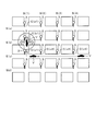
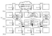
- FIG. 2 is a diagram schematically showing an installation state of a notification device for a road in an urban area
- FIG. 3 is a diagram showing an example of a state of installation of a display device at an intersection
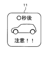
- FIG. 4A is a diagram (part 1) illustrating a display example for a vehicle driver
- FIG. 4B is a diagram (part 2) illustrating a display example for the driver of the vehicle
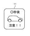
- FIG. 5A is a diagram (part 1) illustrating a display example for a pedestrian;
- FIG. 1 shows an embodiment and is a block diagram schematically showing a configuration of a main part of the system.
- FIG. 2 is a diagram schematically showing an installation state of a notification device for a road in an urban area
- FIG. 3 is a diagram showing an example of a state of installation of a display device at an intersection
- FIG. 4A is a diagram (part 1) illustrating a
- FIG. 5B is a diagram (part 2) illustrating a display example for a pedestrian;
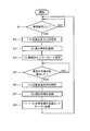
- FIG. 6 is a flowchart showing a procedure of vehicle traffic detection performed by the notification device,
- FIG. 7 is a sequence diagram showing a flow of communication processing until notifying whether a pedestrian can pass safely,
- FIG. 8 is a diagram for explaining a case where a failure occurs.
- FIG. 9A is a diagram (part 1) for explaining a case where a false detection occurs
- FIG. 9B is a diagram (No. 2) for describing a case where an erroneous detection occurs.
- the traffic information notification system 1 is provided in a specific area (city area) as shown in FIG. 2 (and FIG. 8, FIG. 9A, FIG. 9B), for example. Will be described as an example.
- a plurality of roads S living roads through which both vehicles (automobiles) V and pedestrians P pass are east-west direction (right-left direction in the figure) and north-south direction (down-up direction in the figure). It extends in a grid pattern.
- the roads S (a) are sequentially extended from the north side (upper side in the figure) for the road S extending in the east-west direction (left and right in the figure).
- Road S (b) road S (c)
- road S (d) road S (d) and subscripts.
- the road S (1), the road S (2), the road S (3), and the road S (4) are attached in order from the west side (left side in the figure). Expressed with letters.
- intersections C there are a total of 16 intersections (crossroads) C without traffic lights due to the plurality of roads S. As will be described later, these intersections C serve as observation points and notification points.
- the intersection C formed by the road S (b) and the road S (1) is defined as the intersection C (b1), and the road S (c ) And the road S (4), the intersection C is assumed to be an intersection C (c4). In this way, a subscript representing two roads is attached in parentheses after the symbol C.
- FIG. 1 schematically shows a hardware configuration of a traffic information notification system 1 according to the present embodiment.
- the traffic information notification system 1 includes a management server 2 and a plurality of notification devices 3 provided at important points on the road S.
- the notification device 3 has both functions of an information collection terminal provided at an observation point and a notification terminal provided at the notification point, and the information collection terminal and the notification terminal are integrated. It is supposed to be.
- the observation point and the notification point are common, and a plurality of notification points are set at each intersection portion of the road S described above. That is, the notification device 3 is provided at each of the 16 intersections shown in FIG.
- the management server 2 includes a calculation unit 4 mainly composed of a computer. At the same time, the management server 2 communicates wirelessly with the database 5 for accumulating and storing the traffic records respectively connected to the calculation unit 4 and the notification devices 3 (communication devices 8 described later). It has. As will be described in detail later, in the management server 2, the communication device 6 receives real-time traffic records of the vehicle V and the pedestrian P from each notification device 3. At this time, in the traffic record, the position of the intersection C (observation point), the time at which each vehicle V or pedestrian P passed, from which direction the intersection C was entered, and in which direction it was exited (headed) In the case of the vehicle V, license plate information and speed information are included. The received traffic records are accumulated and stored in the database 5.
- the database 5 also stores road map data and the like.
- the management server 2 also includes various road condition data including real-time traffic information, such as traffic prohibition categories, priority roads, presence / absence of construction, traffic jams, road parking / no accidents, etc. Entered.
- the calculation unit 4 performs a prediction process for comprehensively predicting the traffic of the vehicle V and the pedestrian P at each notification point, that is, at the intersection C where the notification device 3 is installed, mainly by its software configuration. This prediction process is performed based on the traffic record received in real time, the past traffic record stored in the database 5, and the road condition data. In this case, it is determined (predicted) when an arbitrary vehicle V and a pedestrian P pass at an arbitrary intersection C.
- the calculating part 4 estimates the traffic of the vehicle V and the pedestrian P in the arbitrary intersection C, the alerting
- the traffic prediction information includes information on when (after what seconds) the vehicle V or the pedestrian P enters the corresponding intersection C and from which direction.
- the calculation unit 4 transmits, to the notification device 3, determination information that determines whether the pedestrian P can pass through the intersection C safely. .
- Each of the notification devices 3 includes a calculation unit 7 mainly composed of a computer, and includes a communication device 8, a pedestrian detection device 9, a vehicle detection device 10, and a display device 11 connected to the calculation unit 7. ing.
- the communication device 8 transmits a real-time traffic record at each intersection C to the management server 2 by wireless communication with the communication device 6.
- the communication device 8 receives the traffic prediction information transmitted from the management server 2.
- the pedestrian detection device 9 detects the passage of the pedestrian P at the intersection C where the notification device 3 is installed.
- the vehicle detection device 10 detects the passage of the vehicle V at the intersection C.
- the pedestrian detection device 9 and the vehicle detection device 10 include, for example, a camera, an image processing device, various sensors for detecting a moving body such as a laser radar, and the like.
- the pedestrian detection device 9 detects traffic records such as the entry / exit time and the entry / exit direction of the pedestrian P with respect to the intersection C. Further, the vehicle detection device 10 detects traffic records such as the entry / exit time of the vehicle V with respect to the intersection C, the entry / exit direction, license plate information photographed by the camera, and speed information. In this way, real-time traffic records of the detected vehicle V and pedestrian P are transmitted from each notification device 3 to the management server 2.
- the display device 11 notifies the driver or pedestrian P of the vehicle V of the traffic prediction information received from the management server 2, that is, the approach information of the other vehicle V or pedestrian P by display.
- the display device 11 is provided with, for example, a plurality of display screens facing different directions in the notification device 3 at one intersection C. That is, the plurality of display screens are provided so that they can be viewed from different directions.
- the access information can be displayed on a plurality of display screens of the display device 11.
- the display device 11 and the notification device 3 as a whole can be installed on, for example, a traffic sign pole 12. It is good also as a structure attached to a utility pole, a curve mirror, etc.
- FIG. 4A, 4B, 5A, and 5B show display examples of approach information on the screen of the display device 11.
- FIG. 4A and 4B notify the driver of the vehicle V that has approached the intersection C that a pedestrian is approaching the intersection C.
- the example of FIG. 4A alerts that a pedestrian will approach the intersection C from the right some seconds later.
- FIG. 4B a state where a pedestrian approaches from the left in several seconds is shown.
- 5A and 5B show an example of informing the driver (and pedestrian P) of the vehicle V that has approached the intersection C that another vehicle V other than the host vehicle is approaching the intersection C. It is shown.
- the example of FIG. 5A alerts that another vehicle V will enter the intersection C from the right in a few seconds.
- a warning is given that another vehicle V will enter the intersection C from the left in a few seconds.
- the notification device 3 when the notification device 3 performs display for the pedestrian P, when the pedestrian P detects that the pedestrian P has entered the intersection C, the notification device 3 notifies the management server 2 of the pedestrian P. A request is made to predict whether or not the intersection C can be safely passed. Then, a warning or the like is displayed on the display device 11 based on the prediction result from the management server 2. In this case, although not shown in FIGS. 5A and 5B, when it is determined that the management server 2 is safe, it is possible to display to the pedestrian P that the display device 11 can be safely passed. It is.
- the calculation unit 4 of the management server 2 predicts the passage of the vehicle V or the pedestrian P at each notification point (intersection C). At this time, the calculation unit 4 determines when (after a few seconds) the vehicle V or the pedestrian P passes to the corresponding intersection C from the traffic record received in real time and the past traffic record stored in the database 5. Judgment is made comprehensively. In particular, when the traveling direction of the vehicle V is predicted, the prediction is performed with reference to the past traffic history of the vehicle V based on the vehicle identification information (number plate information).
- the arithmetic unit 4 of the management server 2 has the pedestrian detection device 9 and the vehicle detection device when there is a contradiction in information among a plurality of traffic records transmitted from each notification device 3. 10 misdetections or device abnormalities are determined.
- FIG. 6 shows a processing procedure related to detection of traffic of the vehicle V, which is executed by the calculation unit 7 of the notification device 3.
- step S1 it is determined by the vehicle detection device 10 whether or not the vehicle V has entered the intersection C.
- step S2 the entrance of the intersection C (for example, which direction has entered from east, west, south, and north) is specified.
- step S3 entry time is recorded.
- step S4 license plate information of the vehicle V is specified.
- step S5 it is determined whether or not the vehicle V has left the intersection C.
- step S6 (4) the exit of the intersection C (for example, which direction has been exited from east, west, south, and north) is specified. Is done.
- step S7 (5) the exit time is recorded.
- step S8 the information (1) to (5) described above is transmitted to the management server 2 as the traffic record of the vehicle V.
- a specific vehicle V enters the road S (c) from the east side, and proceeds straight in order at the intersection C (c4), the intersection C (c3), and the intersection C (c2) (west ) And turn right (exit north) at intersection C (c1).
- the license plate information of the vehicle V is transmitted to the management server 2 in real time.
- a straight traveling record of the vehicle V at the time immediately after that is transmitted from the notification device 3 at the intersection C (c3) to the management server 2 in real time. Furthermore, the straight traveling record of the vehicle V at the time immediately after the notification device 3 at the intersection C (c2) is transmitted to the management server 2 in real time. Then, from the notification device 3 at the intersection C (c1), at the time immediately after that, a traffic record including information that the vehicle V entered from the east and left to the north (turned right), etc., is sent to the management server 2 in real time. Sent.
- the calculation unit 4 of the management server 2 determines which intersection of the vehicle V from the received real-time traffic record, the history information of the traffic record of the vehicle V accumulated in the database 5, and other traffic information. Comprehensively predict how C will pass. In this case, the calculation unit 4 predicts that the probability of the vehicle V making a right turn is the lowest at the next intersection C (b1). In addition, for either straight ahead or left turn, for example, from the past history of the vehicle V, if there are many cases in which the vehicle has customarily gone straight, it is predicted that the probability of going straight is the highest. Alternatively, in consideration of road conditions, for example, when a straight road is congested, it may be determined that the probability of making a left turn is high.
- the management server 2 notifies the notification device 3 of the next intersection C (a1) when the corresponding vehicle V is (after what seconds). Traffic prediction information such as from which direction the intersection C (a1) is entered is transmitted. As shown in FIGS. 5A and 5B, the notification device 3 at the intersection C (a1) that has received the traffic prediction information indicates on which direction the vehicle V enters the intersection C from which direction in seconds. Is displayed. Thereby, the driver or pedestrian of the other vehicle V near the intersection C (a1) can know from which timing and from which direction the vehicle V approaches by looking at the display on the display device 11.
- FIG. 7 shows a communication sequence between the management server 2 and the notification device 3 that detects the pedestrian P and the n notification devices 3 in the vicinity thereof (illustrated as the first and nth two). Is shown.
- the traffic records of the vehicle V are transmitted to the management server 2 in real time.
- the traffic record is transmitted from the first notification device 3 to the management server 2 (communication processing T1), and the traffic record is transmitted from the nth notification device 3 to the management server 2 (communication processing). T2).
- the management server 2 that has received the traffic record of the vehicle V stores the traffic record in the database 5.
- the notification device 3 that has detected the pedestrian P by the pedestrian detection device 9 requests the management server 2 to predict (determine) whether the pedestrian P can pass through the intersection C safely ( Communication processing T3). Then, the calculation unit 4 of the management server 2 predicts whether or not it can pass safely based on the following information I to III.
- the information I is real-time traffic information of the vehicle V from the n nearby notification devices 3.
- the information of II is the accumulated past traffic information.
- the information of III is information on road conditions around the intersection C.
- the notification device 3 determines whether or not the pedestrian P can safely pass through the intersection C, and transmits the prediction result to the notification device 3 at the intersection C (notification process T4).
- the notification device 3 displays a warning or the like on the display device 11 based on the prediction result transmitted from the management server 2. In this case, when the vehicle V approaches, a display for prompting attention as shown in FIGS. 5A and 5B is displayed on the screen of the display device 11.
- the notification device 3 detects the approach of the pedestrian P
- the pedestrian P is approaching the display device 11 as shown in FIGS. 4A and 4B.
- a message to that effect is displayed.
- the driver of the vehicle V can easily know that the pedestrian P is approaching even at the intersection C where the intersecting road side is a blind spot, for example.
- the calculation unit 4 of the management server 2 detects the vehicle V or the like using a plurality of intersections C as observation points. Accordingly, when there is a contradiction in information among a plurality of traffic records, the calculation unit 4 can determine that there has been a false detection or a device abnormality somewhere.
- FIG. 8 illustrates a case where it can be determined that the device has a failure. That is, when a certain vehicle V is traveling on the road S (c) from east to west, the notification device 3 at the intersection C (c4), the notification device 3 at the intersection C (c3), and the intersection C (c2). The vehicle should be detected in the order of the notification device 3. However, after the notification device 3 at the intersection C (c4) detects the vehicle V, the notification device 3 at the intersection C (c2) next detects the vehicle V, and the notification device 3 at the intersection C (c3) It can be determined that there is a failure, for example, a failure of the vehicle detection device 10.
- FIG. 9A and FIG. 9B illustrate a case where there is a false detection.
- the notification device 3 at the intersection C (c4) detects that the vehicle V is traveling straight (westbound)
- the notification device 3 at the intersection C (c3) makes a right turn ( It is assumed that the northbound) is detected and the notification device 3 at the intersection C (c2) detects that the vehicle V travels straight (westbound).
- the notification device 3 at the intersection C (c2) detects that the vehicle V travels straight (westbound).
- it can be determined that an erroneous detection has occurred in either the notification device 3 at the intersection C (c3) or the notification device 3 at the intersection C (c2).
- the notification device 3 at the intersection C (c3) detects the right turn (north line) of the vehicle V
- the notification device 3 at the intersection C (b3) proceeds straight ahead (north direction) of the vehicle V in order. Detect.
- the notification device 3 at the intersection C (a3) detects the left turn (westbound) of the vehicle V
- the notification device 3 at the intersection C (a2) detects straight travel (westbound) of the vehicle V
- Notification device 3 detects that the vehicle V is traveling straight (westbound). Furthermore, it is assumed that the remaining notification device 3 does not detect the vehicle V.
- the calculation unit 4 of the management server 2 can determine that there has been a false detection or device abnormality somewhere when there is a contradiction in information between the traffic records of the plurality of notification devices 3, It is possible to easily identify the notification device 3 having an erroneous detection or abnormality. As a result, it is possible to promptly cope with the notification device 3 in which the erroneous detection or abnormality is determined.
- the calculation unit 4 of the management server 2 is based on real-time traffic records at a plurality of observation points (intersections C), past traffic record histories, and the like.
- the traffic of the vehicle V and the pedestrian P at each notification point (intersection C) can be predicted comprehensively. As a result, more accurate traffic prediction can be performed.
- the prediction information is transmitted to each notification device 3 at a sufficiently early point in time with respect to the timing when the vehicle V or the pedestrian P passes through the notification point. it can.
- the present embodiment it is possible to predict whether the vehicle V and / or the pedestrian P actually passes the intersection C, which is the notification point, with high accuracy, but the user can notify with sufficient time. An excellent effect that it can be confirmed can be obtained.
- the prediction in the calculation unit 4 of the management server 2 is off, it is possible to make use of the experience in which such prediction is off for the next prediction, and it is possible to make predictions with gradually increasing accuracy. .
- the notification point is set at the intersection C portion of the road S. Therefore, at the intersection C, for example, another vehicle V or a pedestrian P from the side that becomes a blind spot is passed to the user. Can be notified, which is effective.
- it was set as the structure which makes the observation point and the alerting
- the vehicle V since the vehicle V is specified by the license plate and the vehicle specifying information is included in the traffic record, data relating to the specified vehicle V can be accumulated. As a result, it is possible to determine what route the vehicle V has traveled in the past, whether the route or time for which the vehicle travels customarily has been determined, whether there is any hesitation in selecting a route, etc. It is possible to make a prediction of whether or not the vehicle passes through with higher accuracy.
- the display device 11 that can be visually recognized by the driver of the vehicle V is provided in the notification device 3, and the approach information that the other vehicle V or the pedestrian P approaches the notification point is displayed on the screen of the display device 11. Thereby, it becomes possible to inform the driver of the vehicle V of useful information when driving, and safety and the like can be improved.
- the notification device 3 is provided with a display device 11 that can be viewed by the pedestrian P, and the approach information that an arbitrary vehicle V approaches the notification point is displayed on the screen of the display device 11. As a result, it becomes possible for pedestrians to be notified of useful information that the vehicle V is approaching, and safety can be improved.
- the management server 2 transmits the determination information for determining whether the pedestrian P can safely pass through the notification point to the notification device 3, the safety of the pedestrian P is further increased. be able to.
- the calculation unit 4 of the management server 2 is configured to determine a false detection or a device abnormality in the detection device of the notification device 3 when there is a contradiction in information among a plurality of traffic records. .
- the traffic information notification system 1 of the present embodiment since there are a plurality of observation points, if there is a contradiction in information between a plurality of traffic records, there is a false detection or an equipment abnormality somewhere. It is possible to make a judgment, and the identification becomes easy, and a prompt action can be taken.
- the observation point and the notification point are configured to be shared.
- the information point and the notification terminal may be separated as separate devices. You may comprise so that it may install in a body.
- the notification device is provided at the intersection C. However, information other than the intersection such as a branch point of a road, a sharp curve point, or a place where a blind spot becomes large is located and information is provided.
- a collection terminal and a notification terminal can be provided.
- the vehicle V although it comprised so that the traffic of the other vehicle V and the pedestrian P might be notified toward both the driver
- the vehicle V not only an automobile but also a two-wheeled vehicle can be distinguished and detected.
- various changes can be made in the configuration of the detection device that detects a vehicle or a pedestrian.
Landscapes
- Physics & Mathematics (AREA)
- General Physics & Mathematics (AREA)
- Engineering & Computer Science (AREA)
- Architecture (AREA)
- Civil Engineering (AREA)
- Structural Engineering (AREA)
- Traffic Control Systems (AREA)
- Road Signs Or Road Markings (AREA)
Abstract
通行情報報知システム(1)は、管理サーバ(2)と、複数の観測地点に設けられた複数の情報収集用端末(3)と、複数の報知地点に設けられた複数の報知用端末(3)とを含む。各情報収集用端末(3)は、各観測地点における車両及び/又は歩行者の通行を検知し、通行記録をリアルタイムで管理サーバ(2)に送信する。管理サーバ(2)は、受信した通行記録をデータベース(5)に記憶し、リアルタイムで受信した通行記録及びデータベース(5)に記憶されている過去の通行記録から各報知地点における車両及び/又は歩行者の通行を総合的に予測し、予測した通行予測情報を該当する報知地点の報知用端末(3)に送信する。各報知用端末(3)は、管理サーバ(2)から送信された通行予測情報に基づいて当該報知地点における車両及び/又は歩行者の通行を報知する。
Description
本出願は、2016年4月11日に出願された日本出願番号2016-078869号に基づくもので、ここにその記載内容を援用する。
本開示は、道路における車両及び/又は歩行者の通行情報を報知する通行情報報知システムに関する。
従来、車両(自動車)の運転者のための運転支援として、交差点等における他の車両の接近を知らせる車両情報表示装置を、カーブミラーに添設する技術が提案されている(例えば特許文献1参照)。この特許文献1のシステムでは、カーブミラー設置場所から一定距離離れた道路に、車両の通過を検知する地磁気センサからなる車両検知手段を埋設し、車両検知手段が検知した車両通過検知情報を無線通信装置によって表示装置に送信する。そして、表示装置は車両通過検知情報を受信すると、車両が近付いている旨の表示を行うように構成されている。
しかしながら、上記特許文献1に記載された車両情報表示装置では、次のような問題点がある。即ち、特許文献1では、交差点に設けられた表示装置(カーブミラー)の位置と、磁気センサの埋設位置との間の距離が「一定距離離れた」ことが記載されているのみで、具体的な例示は存在しない。仮に、その距離が比較的長いと、磁気センサで検知した車両が、実際に表示装置が設けられた交差点まで到達するか不明であり、車両の検知精度が低いものとなる。つまり、車両が、途中で右左折して当該交差点を通らなかったり、途中の目的地で停止したりすることが考えられる。
この場合、表示装置(カーブミラー)と磁気センサとの間の距離を比較的近い距離にすれば、車両検知の精度は高くなるが、今度は、距離が短いために、車両の検知、表示から実際に車両が交差点に到達するまでの時間が短くなる。そのため、利用者にとって表示の確認のための十分な時間がない状態で、車両が交差点を通過してしまう虞がある。尚、車両検知用の磁気センサに故障が発生した場合でも、その故障が容易に判らない不具合もある。
本開示は、車両及び/又は歩行者が実際に報知地点を通過するかを高い精度で予測できながらも、利用者が時間的な余裕をもって報知を確認することができる通行情報報知システムを提供することを目的とする。
本開示の第一の態様において、通行情報報知システムは、管理サーバと、道路の要所における複数の観測地点に夫々設けられた複数の情報収集用端末と、道路の要所における複数の報知地点に夫々設けられた複数の報知用端末とを含んで構成され、道路における車両及び/又は歩行者の通行情報を報知するシステムであって、前記各情報収集用端末は、前記各観測地点における前記車両及び/又は歩行者の通行を検知する検知装置と、前記検知装置の検知した通行記録をリアルタイムで前記管理サーバに送信する検知情報送信装置とを備え、前記管理サーバは、前記各情報収集用端末から送信された通行記録を受信する受信装置と、受信した通行記録を記憶するデータベースと、前記リアルタイムで受信した通行記録及び前記データベースに記憶されている過去の通行記録から前記各報知地点における前記車両及び/又は歩行者の通行を総合的に予測する予測装置と、前記予測装置の予測した通行予測情報を該当する報知地点の報知用端末に送信する予測情報送信装置とを備え、前記各報知用端末は、前記管理サーバから送信された通行予測情報を受信する受信装置と、前記通行予測情報に基づいて当該報知地点における前記車両及び/又は歩行者の通行を報知する報知装置とを備えている。
これによれば、複数の観測地点に夫々設けられた複数の情報収集用端末において、検知装置により検知された車両及び/又は歩行者の通行記録が、リアルタイムで管理サーバに送信される。管理サーバでは、リアルタイムの通行記録及び過去の通行記録の履歴等に基づいて、各報知地点における車両及び/又は歩行者の通行が、予測装置により総合的に予測される。この場合、複数の観測地点における通行記録を用いることによって、予測装置により精度の高い通行予測を行うことができる。
そして、管理サーバから通行予測情報が送信されることに基づき、複数の報知地点に夫々設けられた各報知用端末においては、報知装置により車両及び/又は歩行者の通行が報知される。報知地点に至る前の複数の観測地点における通行記録から予測できるので、報知地点を車両又は歩行者が通過するタイミングに対し、十分に早い時点で予測情報を報知用端末に送信できる。従って、車両及び/又は歩行者が実際に報知地点を通過するかを高い精度で予測できながらも、利用者が時間的な余裕をもって報知を確認することができる。
本開示についての上記目的およびその他の目的、特徴や利点は、添付の図面を参照しながら下記の詳細な記述により、より明確になる。その図面は、
図1は、一実施形態を示すもので、システムの要部の構成を概略的に示すブロック図であり、
図2は、市街地における道路に対する報知装置の設置状態を模式的に示す図であり、
図3は、交差点における表示装置の設置の様子の一例を示す図であり、
図4Aは、車両の運転者向けの表示例を示す図(その1)であり、
図4Bは、車両の運転者向けの表示例を示す図(その2)であり、
図5Aは、歩行者向けの表示例を示す図(その1)であり、
図5Bは、歩行者向けの表示例を示す図(その2)であり、
図6は、報知装置が実行する車両の通行検知の処理手順を示すフローチャートであり、
図7は、歩行者が安全に通行できるかを通知するまでの通信処理の流れを示すシーケンス図であり、
図8は、故障が発生した場合を説明するための図であり、
図9Aは、誤検出が発生した場合を説明するための図(その1)であり、
図9Bは、誤検出が発生した場合を説明するための図(その2)である。
以下、一実施形態について、図面を参照しながら説明する。尚、本実施形態では、便宜上、例えば図2(及び図8、図9A、図9B)に示すような、ある特定の区域(市街地)に本実施形態に係る通行情報報知システム1を設けた場合を例としながら説明する。この市街地においては、車両(自動車)V及び歩行者Pの双方が通行する複数本の道路S(生活道路)が、東西方向(図で右左方向)、及び、南北方向(図で下上方向)に格子状に延びている。
またこの場合、図2等における複数の道路Sを区別する必要がある場合には、東西(図で左右)方向に延びる道路Sについては、北側(図で上側)から順に、道路S(a)、道路S(b)、道路S(c)、道路S(d)と添え字を付して表現する。一方、南北(図で上下)方向に延びる道路Sについては、西側(図で左側)から順に、道路S(1)、道路S(2)、道路S(3)、道路S(4)と添え字を付して表現する。
これにより、複数本の道路Sによって、信号のない交差点(十字路)Cが全部で16個存在している。後述するように、これら交差点C部分が観測地点及び報知地点となる。このとき、複数の交差点Cのいずれかを特定する必要がある場合には、例えば道路S(b)と道路S(1)とがなす交差点Cを、交差点C(b1)とし、道路S(c)と道路S(4)とがなす交差点Cでは、交差点C(c4)とする。このように、二つの道路を表すような添え字を、符号Cの後に括弧書きで付すこととする。
図1は、本実施形態に係る通行情報報知システム1の、ハードウエア的構成を概略的に示している。この通行情報報知システム1は、管理サーバ2と、道路Sの要所に設けられた複数個の報知装置3とを含んで構成されている。本実施形態では、報知装置3は、観測地点に設けられる情報収集用端末及び報知地点に設けられる報知用端末の双方の機能を有し、情報収集用端末と報知用端末とが一体化されたものとされている。しかも、観測地点と報知地点とが共通していると共に、複数の報知地点は、上記した道路Sの各交差点部分に設定されている。つまり、図2に示す16個の交差点部分に夫々報知装置3が設けられている。
前記管理サーバ2は、コンピュータを主体として構成される演算部4を備える。これと共に、管理サーバ2は、演算部4に夫々接続された通行記録を蓄積記憶するデータベース5、前記各報知装置3(後述する通信装置8)との間で無線通信を行うための通信装置6を備えている。詳しくは後述するように、管理サーバ2においては、前記通信装置6により、各報知装置3から、車両V及び歩行者Pのリアルタイムの通行記録を受信する。このとき、通行記録には、交差点C(観測地点)の位置、個々の車両V又は歩行者Pが通過した時刻、当該交差点Cにどの方向から進入し、どの方向に退出した(向かった)か、車両Vの場合ナンバープレート情報及び速度情報、等が含まれる。受信した通行記録はデータベース5に蓄積記憶される。
また、前記データベース5には、道路地図データ等も記憶されている。管理サーバ2には、通行禁止区分、優先道路か否か、工事の有無、渋滞状況、路上駐車の有無、事故多発地点かどうか等の、リアルタイムの交通情報を含んだ各種の道路状況のデータも入力される。
前記演算部4は、主としてそのソフトウエア的構成により、各報知地点つまり報知装置3が設置された交差点Cにおける車両V及び歩行者Pの通行を総合的に予測する予測処理を行う。この予測処理は、リアルタイムで受信した通行記録及びデータベース5に記憶されている過去の通行記録、更には道路状況データに基づいて行われる。この場合、任意の交差点Cに、任意の車両V及び歩行者Pが、いつ通過するかを判断(予測)する。
そして、演算部4が、任意の交差点Cにおける車両V及び歩行者Pの通行を予測した場合には、通信装置6により、その通行予測情報を該当する交差点Cに設置された報知装置3(後述する通信装置8)に対し送信する。このとき、通行予測情報には、該当する交差点Cに対し、車両V又は歩行者Pが、いつ(何秒後に)、どの方向から進入するかの情報を含むものとなっている。また、演算部4は、交差点C近傍に歩行者Pが存在する場合に、その歩行者Pが当該交差点Cを安全に通行できるかどうかを判断した判断情報を、報知装置3に対して送信する。
前記各報知装置3は、コンピュータを主体として構成される演算部7を備えると共に、この演算部7に接続された、通信装置8、歩行者検知装置9、車両検知装置10、表示装置11を備えている。そのうち通信装置8は、前記通信装置6との間の無線通信により、各交差点Cにおけるリアルタイムの通行記録を、前記管理サーバ2に送信する。また通信装置8は、管理サーバ2から送信された通行予測情報を受信する。
前記歩行者検知装置9は、報知装置3が設置された交差点Cにおける歩行者Pの通行を検知するものである。前記車両検知装置10は、当該交差点Cにおける車両Vの通行を検知するものである。詳しい図示は省略するが、これら歩行者検知装置9及び車両検知装置10は、例えば、カメラ及び画像処理装置、レーザレーダ等の移動体検出用の各種センサなどから構成されている。
これにて、歩行者検知装置9により、当該交差点Cに対する歩行者Pの進入退出時刻、進入退出方向といった通行記録が検知される。また、車両検知装置10により、当該交差点Cに対する車両Vの進入退出時刻、進入退出方向、カメラにより撮影されたナンバープレート情報、速度情報といった通行記録が検知される。このように、検知された車両V及び歩行者Pのリアルタイムの通行記録が、各報知装置3から前記管理サーバ2に送信される。
前記表示装置11は、車両Vの運転者或いは歩行者Pに対して、管理サーバ2から受信した通行予測情報つまり他の車両V又は歩行者Pの接近情報を表示によって報知する。図3にも示すように、この表示装置11は、例えば1か所の交差点Cの報知装置3において、複数の表示画面が異なる方向を向いて設けられている。つまり、複数の表示画面は、別々の方向から視認することができるように設けられている。表示装置11の複数の表示画面に、接近情報を表示できるように構成されている。尚、図3の例では、表示装置11更に報知装置3全体は、例えば、交通標識用のポール12に設置できる構成となっている。電柱やカーブミラーなどに取付ける構成としても良い。
図4A、図4B及び図5A、図5Bは、表示装置11の画面における接近情報の表示例を示している。図4A、図4Bは、交差点Cに差し掛かった車両Vの運転者に対し、当該交差点Cに歩行者が近付いていることを報知するものである。図4Aの例は、歩行者が何秒後かに右方から交差点Cに差し掛かる旨を注意喚起するものである。図4Bの例では、歩行者が何秒後かに、左方から近付いてくる様子を示している。
図5A、図5Bは、交差点Cに差し掛かった車両Vの運転者(及び歩行者P)に対し、当該交差点Cに自車両以外の他の車両Vが近付いていることを報知する場合の例を示すものである。図5Aの例は、他の車両Vが何秒後かに右方から交差点Cに進入してくる旨を注意喚起するものである。図5Bの例では、他の車両Vが何秒後かに、左方から交差点Cに進入してくる旨を注意喚起するものである。
尚、本実施形態では、報知装置3は、歩行者P向けの表示を行う場合には、歩行者Pが交差点Cに進入したことを検知すると、管理サーバ2に対して、その歩行者Pが該当交差点Cを安全に通行できるかどうかの予測の依頼を行う。そして、管理サーバ2からの予測結果に基づいた表示装置11に注意などの表示を行う。この場合、図5A、図5Bでは図示されていないが、管理サーバ2にて安全と判断された場合には、歩行者Pに対し、表示装置11に安全に通行できる旨を表示することも可能である。
さて、次の作用説明でも述べるように、前記管理サーバ2の演算部4は、各報知地点(交差点C)における車両V又は歩行者Pの通行を予測する。このとき、演算部4は、リアルタイムで受信した通行記録及びデータベース5に記憶されている過去の通行記録から、該当する交差点Cに対し、車両V又は歩行者Pが、いつ(何秒後に)通過するのかを、総合的に判断する。特に車両Vの走行方向を予測する場合には、車両特定情報(ナンバープレート情報)に基づき、該当車両Vの過去の通行の履歴を参照しながら予測を行う。
また、管理サーバ2の演算部4は、上記したように、報知装置3からの歩行者Pの安全判断の依頼を受けると、当該交差点Cを歩行者Pが安全に通行できるかどうか(通行する車両Vはないか)を判断予測して、当該報知装置3に対しその予測結果を送信する。更に、特に本実施形態では、前記管理サーバ2の演算部4は、各報知装置3から送信される複数の通行記録間で情報に矛盾があった場合に、歩行者検知装置9及び車両検知装置10の誤検知又は機器異常を判定する。
次に、上記のように構成された通行情報報知システム1の作用について、図6から図9Bも参照して述べる。まず、図6のフローチャートは、報知装置3の演算部7が実行する、車両Vの通行の検知に関する処理手順を示している。
即ち、まずステップS1では、車両検知装置10により、交差点Cへの車両Vの進入を検知したかどうかが判断される。車両Vを検知した場合には(ステップS1にてYes)、ステップS2にて、(1)交差点Cの進入口(例えば東西南北のいずれの方向から進入したか)が特定される。ステップS3では、(2)進入時刻が記録される。更に、ステップS4では、(3)車両Vのナンバープレート情報が特定される。
次のステップS5では、車両Vが当該交差点Cを退出したかどうかが判断される。車両Vが当該交差点Cを退出したと判断されると(ステップS5にてYes)、ステップS6にて、(4)交差点Cの退出口(例えば東西南北のいずれの方向に退出したか)が特定される。続くステップS7にて、(5)退出時刻が記録される。そして、ステップS8にて、上記した(1)~(5)の情報が、車両Vの通行記録として、管理サーバ2に送信される。
ここで、図2を参照しながら、具体例について述べる。図2に点線の矢印で示すように、特定の車両Vが、道路S(c)に東側から進入し、交差点C(c4)、交差点C(c3)、交差点C(c2)を順に直進(西へ走行)し、交差点C(c1)で右折(北方向に退出)したものとする。このとき、まず交差点C(c4)の報知装置3から、車両Vのナンバープレート情報、交差点C(c4)に東から進入し西に退出した(直進した)情報、その通過(進入、退出)時刻といった通行記録が、管理サーバ2にリアルタイムで送信される。
次いで、交差点C(c3)の報知装置3から、該当車両Vの、その直後の時刻における直進の通行記録が管理サーバ2にリアルタイムで送信される。さらに、交差点C(c2)の報知装置3から、その直後の時刻における該当車両Vの直進の通行記録が管理サーバ2にリアルタイムで送信される。そして、交差点C(c1)の報知装置3から、その直後の時刻において、該当車両Vが、東から進入し北に退出した(右折した)情報等からなる通行記録が、管理サーバ2にリアルタイムで送信される。
管理サーバ2の演算部4は、受信したリアルタイムの通行記録や、データベース5に蓄積された該当車両Vにおける通行記録の履歴情報、その他の交通情報を含む道路状況から、該当車両Vが、どの交差点Cをどのように通行するかを総合的に予測する。この場合、演算部4は、次の交差点C(b1)においては、該当車両Vが右折する確率が最も低いと予測する。また、直進、左折のいずれかについては、例えば該当車両Vの過去の履歴から、習慣的に直進したケースが多い場合には、直進する確率が最も高いと予測する。或いは、道路状況を考慮して、例えば直進の道路が渋滞している場合には、左折する確率が高いと判断する場合もある。
演算部4が例えば直進する確率が最も高いと判断(予測)した場合には、管理サーバ2から次の交差点C(a1)の報知装置3に対し、該当車両Vがいつ(何秒後に)、どの方向からその交差点C(a1)に進入するかといった通行予測情報が送信される。通行予測情報を受信した交差点C(a1)の報知装置3は、図5A、図5Bに示すように、表示装置11に、車両Vが何秒後かに、どの方向から交差点Cに進入するかを表示する。これにより、交差点C(a1)付近の他の車両Vの運転者又は歩行者は、表示装置11の表示を見て、どのタイミングでどの方向から車両Vが近付いて来るかを知ることができる。
次に、図7を参照して、報知装置3から歩行者Pの安全判断の依頼を管理サーバ2に送信した場合の処理について述べる。図7は、歩行者Pを検知した報知装置3及びその周辺のn個(1番目とn番目との2個を代表させて図示)の報知装置3と、管理サーバ2との間の通信シーケンスを示している。
ここで、上記したように、周辺のn個の報知装置3は、車両Vを検知すると、その車両Vの通行記録を管理サーバ2に対しリアルタイムで送信する。図7では、1番目の報知装置3から通行記録が管理サーバ2に送信され(通信処理T1)、これと共に、n番目の報知装置3から通行記録が管理サーバ2に送信されている(通信処理T2)。車両Vの通行記録を受信した管理サーバ2は、その通行記録をデータベース5に保存する。
一方、歩行者検知装置9により歩行者Pを検知した報知装置3は、管理サーバ2に対し、当該歩行者Pが、当該交差点Cを安全に通行できるかの予測(判断)の依頼を行う(通信処理T3)。すると、管理サーバ2の演算部4は、次のI~IIIの情報から総合的に、安全に通行できるかどうかを予測する。Iの情報は、n個の周辺の報知装置3からのリアルタイムの車両Vの通行情報である。IIの情報は、蓄積された過去の通行情報である。IIIの情報は、交差点C周辺の道路状況の情報である。
報知装置3は、当該交差点Cを歩行者Pが安全に通行できるかどうかを判断予測して、当該交差点Cの報知装置3に対しその予測結果を送信する(通知処理T4)。報知装置3は、管理サーバ2から送信された予測結果に基づいた表示装置11に注意などの表示を行う。この場合、車両Vが近付いてくる場合には、表示装置11の画面には、図5A、Bに示すような注意喚起を促す表示がなされる。
尚、このとき、報知装置3(歩行者検知装置9)が歩行者Pの接近を検知した場合、図4A、図4Bに示すように、表示装置11には、歩行者Pが接近している旨の表示がなされる。車両Vの運転者は、それを見て、例えば交差する道路側が死角になっているような交差点Cであっても、歩行者Pが近付いていることを容易に知ることができる。
ところで、この通行情報報知システム1にあっては、管理サーバ2の演算部4は、複数の交差点Cを夫々観測地点として車両Vなどを検知している。従って、演算部4は、複数の通行記録間で情報に矛盾があった場合には、どこかで誤検知或いは機器異常があったと判定することができる。
図8は、機器に故障があると判断できるケースを例示している。即ち、ある車両Vが、道路S(c)を東から西に向かって走行している場合、交差点C(c4)の報知装置3、交差点C(c3)の報知装置3、交差点C(c2)の報知装置3の順に車両を検知するはずである。ところが、交差点C(c4)の報知装置3が車両Vを検知した後、次に交差点C(c2)の報知装置3当該車両Vを検知した場合には、交差点C(c3)の報知装置3に故障、例えば車両検知装置10の故障があると判断することができる。
また、図9A、図9Bは、誤検知があった場合を例示している。ここで、仮に図9Aに示すように、交差点C(c4)の報知装置3が車両Vの直進(西行)を検知した後、交差点C(c3)の報知装置3が、当該車両Vの右折(北行)を検知し、且つ、交差点C(c2)の報知装置3が、当該車両Vの直進(西行)を検知したとする。この場合、車両Vの検知に矛盾が生じているので、交差点C(c3)の報知装置3か、又は、交差点C(c2)の報知装置3のどちらかに誤検知が発生したと判断できる。
このような場合には、別の交差点Cにおける走行記録から、どちらの報知装置3に誤検知が発生したかを判断することができる。図9Bでは、交差点C(c3)の報知装置3が当該車両Vの右折(北行)を検知した後に、順に、交差点C(b3)の報知装置3が当該車両Vの直進(北行)を検知する。引続き、交差点C(a3)の報知装置3が当該車両Vの左折(西行)を検知し、交差点C(a2)の報知装置3が当該車両Vの直進(西行)を検知し、交差点C(a1)の報知装置3が当該車両Vの直進(西行)を検知したものとする。更に、残りの報知装置3においては、車両Vを検知していないものとする。
これにより、交差点C(c2)の報知装置3に誤検知が発生したと判断することができる。このように、管理サーバ2の演算部4は、複数の報知装置3の通行記録間で情報に矛盾があった場合には、どこかで誤検知或いは機器異常があったと判断することができ、誤検知又は異常のある報知装置3の特定を容易に行うことができる。ひいては、誤検知又は異常が判断された報知装置3に対する速やかな対処が可能となる。
このように、本実施形態の通行情報報知システム1によれば、管理サーバ2の演算部4は、複数の観測地点(交差点C)におけるリアルタイムの通行記録及び過去の通行記録の履歴等に基づいて、各報知地点(交差点C)における車両V及び歩行者Pの通行を総合的に予測することができる。この結果、より精度の高い通行予測を行うことができる。そして、報知地点に至る前の複数の観測地点における通行記録から予測できるので、報知地点を車両V又は歩行者Pが通過するタイミングに対し、十分に早い時点で予測情報を各報知装置3に送信できる。
この結果、本実施形態によれば、車両V及び/又は歩行者Pが実際に報知地点である交差点Cを通過するかを高い精度で予測できながらも、利用者が時間的な余裕をもって報知を確認することができるという優れた効果を得ることができる。尚、管理サーバ2の演算部4における予測が外れることも考えらえるが、そのような予測が外れた経験を次の予測に生かすことができ、次第に精度を高めながら予測することが可能となる。
特に本実施形態では、報知地点を、道路Sの交差点C部分に設定するようにしたので、交差点Cにおいて、利用者に対し、例えば死角となる側からの他車両Vや歩行者Pなどの通行を報知することができ、効果的となる。また、本実施形態では、観測地点と報知地点とを共通させ、当該地点に情報収集用端末及び報知用端末とを一体化した形態の報知装置3を設ける構成とした。そのため、情報収集用端末及び報知用端末の設置や取扱い、メンテナンス等が容易となる。
本実施形態では、ナンバープレートにより車両Vを特定し、通行記録に、その車両特定情報を含ませる構成としたので、特定された車両Vに関するデータの蓄積が可能となる。これにより、当該車両Vが過去にどのような経路を走行したのか、習慣的に走行する経路や時間等が決まっているのか、経路を選ぶにあたって癖があるのか等を求めることができ、どの経路を通るかの予測をより一層精度高く行うことができるようになる。
報知装置3に、車両Vの運転者が視認可能な表示装置11を設け、他の車両V又は歩行者Pが報知地点に接近する接近情報を表示装置11の画面に表示するようにした。これにより、車両Vの運転者に、運転する際の有用な情報を報知することが可能となり、安全性などを高めることができる。これと共に、報知装置3に、歩行者Pが視認可能な表示装置11を設け、任意の車両Vが報知地点に接近する接近情報を表示装置11の画面に表示するようにした。この結果、歩行者にとって、車両Vの接近という有用な情報を報知することが可能となり、安全性を高めることができる。このとき、管理サーバ2から、歩行者Pが当該報知地点を安全に通行できるかどうかを判断した判断情報を報知装置3に対して送信するようにしたので、歩行者Pの安全性をより高めることができる。
更に、本実施形態では、管理サーバ2の演算部4は、複数の通行記録間で情報に矛盾があった場合に、報知装置3の検知装置における誤検知又は機器異常を判定するように構成した。本実施形態の通行情報報知システム1においては、複数の観測地点を有しているので、複数の通行記録間で情報に矛盾があった場合には、どこかで誤検知或いは機器異常があったと判断することができ、その特定も容易となり、速やかな対処が可能となる。
尚、上記した実施形態では、観測地点と報知地点とを共通させるように構成したが、必ずしも完全一致していなくても良く、情報取集用端末と報知用端末とを別々の装置として、別体に設置するように構成しても良い。また、上記実施形態では、報知装置を交差点C部分に設けるようにしたが、交差点以外でも、道路の分岐地点や急カーブ地点、その他死角が大きくなる場所など、道路の要所に位置して情報取集用端末や報知用端末を設けることができる。
更に、上記実施形態では、車両Vの運転者及び歩行者Pの双方に向けて、他の車両Vや歩行者Pの通行を報知するように構成したが、例えば車両Vのみを対象として、その通行情報を収集し、報知するように構成する等も可能である。車両Vとして、自動車だけでなく二輪車なども、区別して検知するように構成することができる。その他、車両や歩行者を検知する検知装置の構成としても様々な変更が可能である。
本開示は、実施例に準拠して記述されたが、本開示は当該実施例や構造に限定されるものではないと理解される。本開示は、様々な変形例や均等範囲内の変形をも包含する。加えて、様々な組み合わせや形態、さらには、それらに一要素のみ、それ以上、あるいはそれ以下、を含む他の組み合わせや形態をも、本開示の範疇や思想範囲に入るものである。
Claims (8)
- 管理サーバ(2)と、
道路の要所における複数の観測地点に夫々設けられた複数の情報収集用端末(3)と、
道路の要所における複数の報知地点に夫々設けられた複数の報知用端末(3)とを含んで構成され、道路における車両及び/又は歩行者の通行情報を報知するシステム(1)であって、
前記各情報収集用端末(3)は、前記各観測地点における前記車両及び/又は歩行者の通行を検知する検知装置(9,10)と、前記検知装置(9,10)の検知した通行記録をリアルタイムで前記管理サーバ(2)に送信する検知情報送信装置(6)とを備え、
前記管理サーバ(2)は、前記各情報収集用端末(3)から送信された通行記録を受信する受信装置(6)と、受信した通行記録を記憶するデータベース(5)と、前記リアルタイムで受信した通行記録及び前記データベース(5)に記憶されている過去の通行記録から前記各報知地点における前記車両及び/又は歩行者の通行を総合的に予測する予測装置(4)と、前記予測装置(4)の予測した通行予測情報を該当する報知地点の報知用端末(3)に送信する予測情報送信装置(6)とを備え、
前記各報知用端末(3)は、前記管理サーバ(2)から送信された通行予測情報を受信する受信装置(8)と、前記通行予測情報に基づいて当該報知地点における前記車両及び/又は歩行者の通行を報知する報知装置(11)とを備える通行情報報知システム。 - 前記報知地点は、道路の交差点部分に設定される請求項1記載の通行情報報知システム。
- 前記観測地点と報知地点とは共通しており、当該地点に前記情報収集用端末及び報知用端末(3)が、一体化された形態で設けられている請求項1又は2記載の通行情報報知システム。
- 前記検知装置(9,10)は、ナンバープレートにより車両を特定する車両特定装置を備え、前記通行記録には、その車両特定情報が含まれる請求項1から3のいずれか一項に記載の通行情報報知システム。
- 前記報知装置(11)は、車両の運転者が視認可能な表示装置を備え、他の車両又は歩行者が当該報知地点に接近する接近情報を前記表示装置の画面に表示する請求項1から4のいずれか一項に記載の通行情報報知システム。
- 前記報知装置(11)は、歩行者が視認可能な表示装置を備え、任意の車両が当該報知地点に接近する接近情報を前記表示装置の画面に表示する請求項1から5のいずれか一項に記載の通行情報報知システム。
- 前記管理サーバ(2)は、前記報知地点近傍に歩行者が存在する場合に、その歩行者が当該報知地点を安全に通行できるかどうかを判断した判断情報を前記報知用端末(3)に対して送信する請求項6記載の通行情報報知システム。
- 前記管理サーバ(2)は、複数の通行記録間で情報に矛盾があった場合に、前記検知装置(9,10)における誤検知又は機器異常を判定する判定装置(4)を備える請求項1から7のいずれか一項に記載の通行情報報知システム。
Priority Applications (1)
| Application Number | Priority Date | Filing Date | Title |
|---|---|---|---|
| SG11201808068RA SG11201808068RA (en) | 2016-04-11 | 2017-02-15 | Passage information notification system |
Applications Claiming Priority (2)
| Application Number | Priority Date | Filing Date | Title |
|---|---|---|---|
| JP2016078869A JP6508108B2 (ja) | 2016-04-11 | 2016-04-11 | 通行情報報知システム |
| JP2016-078869 | 2016-04-11 |
Publications (1)
| Publication Number | Publication Date |
|---|---|
| WO2017179288A1 true WO2017179288A1 (ja) | 2017-10-19 |
Family
ID=60041752
Family Applications (1)
| Application Number | Title | Priority Date | Filing Date |
|---|---|---|---|
| PCT/JP2017/005511 Ceased WO2017179288A1 (ja) | 2016-04-11 | 2017-02-15 | 通行情報報知システム |
Country Status (4)
| Country | Link |
|---|---|
| JP (1) | JP6508108B2 (ja) |
| EE (1) | EE201800026A (ja) |
| SG (1) | SG11201808068RA (ja) |
| WO (1) | WO2017179288A1 (ja) |
Citations (2)
| Publication number | Priority date | Publication date | Assignee | Title |
|---|---|---|---|---|
| JPS59151299A (ja) * | 1983-02-16 | 1984-08-29 | 芦立電気株式会社 | 車輛接近警告装置 |
| JP2016048442A (ja) * | 2014-08-27 | 2016-04-07 | 富士通株式会社 | 車両情報出力プログラム、車両情報出力方法及び車両情報出力装置 |
Family Cites Families (4)
| Publication number | Priority date | Publication date | Assignee | Title |
|---|---|---|---|---|
| JP3591243B2 (ja) * | 1997-10-06 | 2004-11-17 | 住友電気工業株式会社 | 旅行時間計測方法、旅行時間計測装置及び旅行時間計測システム |
| JP4952429B2 (ja) * | 2007-08-02 | 2012-06-13 | 株式会社デンソー | 運転支援システム |
| JP5151716B2 (ja) * | 2008-06-16 | 2013-02-27 | 株式会社デンソー | 車両走行支援システム、路上側システム及び車両側システム |
| JP2010211301A (ja) * | 2009-03-06 | 2010-09-24 | Toshiba Corp | 事故予測通知装置、事故予測通知システム及び車載器 |
-
2016
- 2016-04-11 JP JP2016078869A patent/JP6508108B2/ja not_active Expired - Fee Related
-
2017
- 2017-02-15 SG SG11201808068RA patent/SG11201808068RA/en unknown
- 2017-02-15 WO PCT/JP2017/005511 patent/WO2017179288A1/ja not_active Ceased
- 2017-02-15 EE EEP201800026A patent/EE201800026A/et unknown
Patent Citations (2)
| Publication number | Priority date | Publication date | Assignee | Title |
|---|---|---|---|---|
| JPS59151299A (ja) * | 1983-02-16 | 1984-08-29 | 芦立電気株式会社 | 車輛接近警告装置 |
| JP2016048442A (ja) * | 2014-08-27 | 2016-04-07 | 富士通株式会社 | 車両情報出力プログラム、車両情報出力方法及び車両情報出力装置 |
Also Published As
| Publication number | Publication date |
|---|---|
| JP6508108B2 (ja) | 2019-05-08 |
| JP2017191366A (ja) | 2017-10-19 |
| SG11201808068RA (en) | 2018-10-30 |
| EE201800026A (et) | 2018-11-15 |
Similar Documents
| Publication | Publication Date | Title |
|---|---|---|
| US11257377B1 (en) | System for identifying high risk parking lots | |
| JP4984244B2 (ja) | 交差点安全運転支援装置 | |
| CN101652802B (zh) | 安全驾驶支持装置 | |
| CN111354187A (zh) | 用于辅助交通工具的驾驶员的方法和驾驶员辅助系统 | |
| JP6537631B2 (ja) | 予測装置、予測システム、予測方法および予測プログラム | |
| US20150253772A1 (en) | Apparatus and method for continuously establishing a boundary for autonomous driving availability and an automotive vehicle comprising such an apparatus | |
| WO2016009600A1 (ja) | 運転支援装置 | |
| JP7135904B2 (ja) | 交通管理システム及びその制御方法 | |
| JP2006072830A (ja) | 運転支援システム及び運転支援モジュール | |
| JP7362733B2 (ja) | 道路環境情報の自動化クラウドソーシング | |
| JP2010211301A (ja) | 事故予測通知装置、事故予測通知システム及び車載器 | |
| JP7165827B2 (ja) | 自動車の支援方法 | |
| US11644324B2 (en) | Dangerous place identification device, map data, dangerous place identification method, and program | |
| JP2009031196A (ja) | 情報通知システム及びプログラム | |
| JP2017062583A (ja) | 危険情報報知システム、サーバ及びコンピュータプログラム | |
| JP5338371B2 (ja) | 車両用警報装置 | |
| JP4258485B2 (ja) | 車両の追い越し支援装置 | |
| US20190205669A1 (en) | Detection of a dangerous situation in road trffic | |
| JP2019020910A (ja) | 車線変更支援方法 | |
| US11328592B2 (en) | Systems and methods for roadway obstruction detection | |
| JP4900120B2 (ja) | 駐停車判定装置 | |
| JP4961311B2 (ja) | 運転支援装置及び運転支援方法 | |
| JP6508108B2 (ja) | 通行情報報知システム | |
| CN112950995B (zh) | 泊车辅助装置、辅助装置、相应方法及车辆和服务器 | |
| JP2019212190A (ja) | 運転支援装置 |
Legal Events
| Date | Code | Title | Description |
|---|---|---|---|
| WWE | Wipo information: entry into national phase |
Ref document number: 11201808068R Country of ref document: SG |
|
| NENP | Non-entry into the national phase |
Ref country code: DE |
|
| 121 | Ep: the epo has been informed by wipo that ep was designated in this application |
Ref document number: 17782107 Country of ref document: EP Kind code of ref document: A1 |
|
| 122 | Ep: pct application non-entry in european phase |
Ref document number: 17782107 Country of ref document: EP Kind code of ref document: A1 |