WO2017175820A1 - 非常操作弁およびアンロード回路 - Google Patents
非常操作弁およびアンロード回路 Download PDFInfo
- Publication number
- WO2017175820A1 WO2017175820A1 PCT/JP2017/014320 JP2017014320W WO2017175820A1 WO 2017175820 A1 WO2017175820 A1 WO 2017175820A1 JP 2017014320 W JP2017014320 W JP 2017014320W WO 2017175820 A1 WO2017175820 A1 WO 2017175820A1
- Authority
- WO
- WIPO (PCT)
- Prior art keywords
- valve
- emergency operation
- chamber
- oil passage
- hydraulic
- Prior art date
- Legal status (The legal status is an assumption and is not a legal conclusion. Google has not performed a legal analysis and makes no representation as to the accuracy of the status listed.)
- Ceased
Links
Images



Classifications
-
- B—PERFORMING OPERATIONS; TRANSPORTING
- B66—HOISTING; LIFTING; HAULING
- B66C—CRANES; LOAD-ENGAGING ELEMENTS OR DEVICES FOR CRANES, CAPSTANS, WINCHES, OR TACKLES
- B66C13/00—Other constructional features or details
- B66C13/18—Control systems or devices
- B66C13/20—Control systems or devices for non-electric drives
-
- F—MECHANICAL ENGINEERING; LIGHTING; HEATING; WEAPONS; BLASTING
- F15—FLUID-PRESSURE ACTUATORS; HYDRAULICS OR PNEUMATICS IN GENERAL
- F15B—SYSTEMS ACTING BY MEANS OF FLUIDS IN GENERAL; FLUID-PRESSURE ACTUATORS, e.g. SERVOMOTORS; DETAILS OF FLUID-PRESSURE SYSTEMS, NOT OTHERWISE PROVIDED FOR
- F15B11/00—Servomotor systems without provision for follow-up action; Circuits therefor
- F15B11/02—Systems essentially incorporating special features for controlling the speed or actuating force of an output member
- F15B11/028—Systems essentially incorporating special features for controlling the speed or actuating force of an output member for controlling the actuating force
-
- F—MECHANICAL ENGINEERING; LIGHTING; HEATING; WEAPONS; BLASTING
- F15—FLUID-PRESSURE ACTUATORS; HYDRAULICS OR PNEUMATICS IN GENERAL
- F15B—SYSTEMS ACTING BY MEANS OF FLUIDS IN GENERAL; FLUID-PRESSURE ACTUATORS, e.g. SERVOMOTORS; DETAILS OF FLUID-PRESSURE SYSTEMS, NOT OTHERWISE PROVIDED FOR
- F15B20/00—Safety arrangements for fluid actuator systems; Applications of safety devices in fluid actuator systems; Emergency measures for fluid actuator systems
-
- F—MECHANICAL ENGINEERING; LIGHTING; HEATING; WEAPONS; BLASTING
- F16—ENGINEERING ELEMENTS AND UNITS; GENERAL MEASURES FOR PRODUCING AND MAINTAINING EFFECTIVE FUNCTIONING OF MACHINES OR INSTALLATIONS; THERMAL INSULATION IN GENERAL
- F16K—VALVES; TAPS; COCKS; ACTUATING-FLOATS; DEVICES FOR VENTING OR AERATING
- F16K31/00—Actuating devices; Operating means; Releasing devices
- F16K31/12—Actuating devices; Operating means; Releasing devices actuated by fluid
- F16K31/36—Actuating devices; Operating means; Releasing devices actuated by fluid in which fluid from the circuit is constantly supplied to the fluid motor
- F16K31/363—Actuating devices; Operating means; Releasing devices actuated by fluid in which fluid from the circuit is constantly supplied to the fluid motor the fluid acting on a piston
Definitions
- the present invention relates to an emergency operation valve and an unload circuit. More particularly, the present invention relates to an emergency operation valve and an unload circuit used in a hydraulic working machine such as a truck-mounted crane.
- the truck-mounted crane has a mechanical configuration in which a hook suspended by a wire from the tip of a crane boom is wound up and down with a winch, and a hydraulic circuit that drives the winch. Since the hook or boom is damaged if the hook is wound too much, the hydraulic circuit is provided with an unload circuit for stopping the winch drive.
- a so-called hook overwinding prevention device includes such an unload circuit.
- the unload circuit is configured by a relief valve and an electromagnetic on-off valve interposed in a pilot circuit of the relief valve.
- Such an unload circuit is configured to unload or on-load hydraulic oil by applying / releasing pilot pressure by the electromagnetic on-off valve.
- the unload circuits of Patent Documents 1 and 2 constitute an antitheft device and do not constitute an overwinding prevention device for hooks.
- the unload circuit 100 constituting the hook overwinding prevention device in the truck-mounted crane will be described with reference to FIG.
- the hydraulic oil discharged by the hydraulic pump 101 is supplied to each hydraulic actuator through the supply oil passage 102.
- the hydraulic oil discharged from each hydraulic actuator is returned to the tank 104 through the discharged oil passage 103.
- a relief valve 105 is interposed between the supply oil passage 102 and the discharge oil passage 103.
- the relief valve 105 is closed when the spring pressing force and the pilot pressure are combined, and enters an on-load state in which hydraulic oil flows through the supply oil passage 102.
- the relief valve 105 is opened when the pilot pressure is exhausted.
- An electromagnetic on-off valve 106 for switching and controlling the supply / discharge of the pilot pressure is provided.
- the truck-mounted crane is provided with a limit switch 109 for detecting over-winding of the hook at the tip of the boom.
- the limit switch 109 detects an overwinding of the hook, the electromagnetic on-off valve 106 is opened to release the pilot pressure. Then, the relief valve 105 is opened, and the drive of the winch motor is stopped.
- a manual on-off valve 120 is interposed in series with the electromagnetic on-off valve 106 as an emergency operation valve.
- the relief valve 105 is also closed. Then, the hydraulic oil is on-loaded to the supply oil passage 102, and the crane can be moved.
- the conventional emergency operation valve 120 is configured as shown in FIG.
- a pump side passage 122 and a tank side passage 123 are formed in the valve box 121.
- a valve chamber 124 is formed at a position where the pump side passage 122 and the tank side passage 123 intersect, and a valve body 125 is inserted therein.
- the valve body 125 is a screw-in type, and a male screw of the valve body 125 meshes with a female screw 126 formed in the valve box 121. Inserting a screwdriver into a concave groove 127 formed in the head of the valve body 125 and rotating it forward and backward to move the valve body 125 forward and backward causes the pump side passage 122 and the tank side passage 123 to communicate with each other or shut off. be able to.
- the emergency operation valve 120 if the valve body 125 is screwed in, the pump side passage 122 and the tank side passage 123 are blocked, and the pilot pressure can continue to be applied to the relief valve 105 shown in FIG. However, since the emergency operation valve 120 is a manual operation, the winch motor can be operated unless it is remembered and released. If the winch motor continues to operate, damage due to overwinding of the hook may occur.
- an object of the present invention is to provide an emergency operation valve that does not forget to be released and an unload circuit using the emergency operation valve.
- One aspect of the emergency operation valve according to the present invention is an emergency operation valve that can be selectively switched between a valve open state and a valve closed state, and includes a valve box having a hollow valve chamber, and the valve box.
- a resilient member that biases the pressure receiving portion in a direction from the second position toward the first position.
- One aspect of the unload circuit according to the present invention is an unload circuit used in a hydraulic circuit of a hydraulic working machine, and is interposed between a supply oil path connected to a pump and a discharge oil path connected to a tank.
- a relief valve and a pilot pressure control valve for controlling supply and discharge of the pilot pressure to and from the relief valve, and the pilot pressure control valve includes the emergency operation valve described above.
- the possibility of forgetting to release can be reduced.
- FIG. 1A is a valve opening state
- FIG. 1B is a valve closing state.
- FIG. 3A is an operation explanatory diagram of the emergency operation valve in the non-operation state
- FIG. 3B is an operation explanatory diagram of the unload circuit when the emergency operation valve is in the non-operation state
- 4A is an operation explanatory diagram of the emergency operation valve that is manually pushed
- FIG. 4B is an operation explanatory diagram of the unload circuit in a state where the emergency operation valve is manually pushed.
- FIG. 3A is an operation explanatory diagram of the emergency operation valve that is manually pushed
- FIG. 4B is an operation explanatory diagram of the unload circuit in a state where the emergency operation valve is manually pushed.
- FIG. 5A is an operation explanatory view of the emergency operation valve automatically held
- FIG. 5B is an operation explanatory view of the unload circuit in a state where the emergency operation valve is automatically held.
- FIG. 6A is an operation explanatory diagram of the emergency operation valve that has automatically returned
- FIG. 6B is an operation explanatory diagram of the unload circuit in a state in which the emergency operation valve has automatically returned. It is a circuit diagram of the conventional unload circuit. It is sectional drawing of the conventional emergency operation valve.
- the emergency operation valve is an emergency operation valve that can be selectively switched between an open state and a closed state, and has a hollow valve chamber (for example, a valve chamber 12 described later).
- a box for example, a valve box 11 to be described later
- a first oil path for example, a pump side passage 17 to be described later
- a second oil passage for example, a tank side passage 18 to be described later
- a pressure receiving portion (for example, a pressure receiving portion 15 to be described later) disposed in the valve chamber in a possible state, and the first position from the second position.
- Direction towards the location includes a resilient member which urges the pressure receiving portion (e.g., later-described spring 16), the.
- the valve box 11 has a valve chamber 12 formed therein as a cylindrical cavity.
- a valve body 13 is inserted into the valve chamber 12 so as to be able to reciprocate.
- one side (the upper side of FIGS. 1A and 1B) related to the reciprocation of the valve body 13 is also referred to as a first direction, and the other side (the lower side of FIGS. 1A and 1B) is also referred to as a second direction.
- the unloaded state of the emergency operation valve A is the opened state of the emergency operation valve A.
- the on-load state of the emergency operation valve A is a closed state of the emergency operation valve.
- the unload state of the unload circuit is a state in which hydraulic oil can pass through the relief valve 5 (see FIG. 2) of the unload circuit (that is, the relief valve 5 is opened).
- the onload state of the unload circuit is a state in which hydraulic oil cannot pass through the relief valve 5 of the unload circuit (that is, the relief valve 5 is closed).
- the unloaded state of the hydraulic circuit in which the unloaded circuit is incorporated is a state in which hydraulic oil is not supplied to the hydraulic actuator of the hydraulic working machine.
- the on-load state of the hydraulic circuit incorporating the unload circuit is a state in which hydraulic oil is supplied to the hydraulic actuator of the hydraulic working machine.
- the valve element 13 includes a round rod-shaped valve rod 14 and a flange-shaped pressure receiving portion 15 formed at an intermediate portion of the valve rod 14.
- the pressure receiving portion 15 is a member having a diameter larger than that of the valve rod 14.
- a pressure receiving surface that receives the pressure of the hydraulic oil is formed on the upper surface of the pressure receiving portion 15 (that is, the surface on the first direction side).
- a spring-side pressure receiving surface that receives the spring pressure of the spring 16 described later is formed on the lower surface (that is, the surface in the second direction) of the pressure receiving portion 15.
- the pressure receiving part 15 divides the valve chamber 12 into two.
- a space on the valve chamber 12 that is closer to the first direction than the pressure receiving portion 15 (one end side and the upper side in FIGS. 1A and 1B) is referred to as a pressure receiving chamber 12a.
- a space in the valve chamber 12 that is on the second direction side (lower side in FIGS. 1A and 1B) from the pressure receiving portion 15 is referred to as a spring chamber 12b. That is, the pressure receiving unit 15 partitions the valve chamber 12 into a pressure receiving chamber 12a that is a first chamber and a spring chamber 12b that is a second chamber.
- the volume of the pressure receiving chamber 12a and the spring chamber 12b changes according to the reciprocation of the pressure receiving portion 15. As shown in FIG. 1A, in a state where the pressure receiving portion 15 is completely displaced in the first direction of the valve chamber 12, the volume of the pressure receiving chamber 12a is the smallest and the volume of the spring chamber 12b is the largest.
- a spring 16 that is an example of an elastic member is disposed in the spring chamber 12b.
- the upper end of the spring 16 is in contact with the lower surface of the pressure receiving portion 15 (that is, the spring side pressure receiving surface).
- the lower end of the spring 16 is in contact with the end surface of the inner surface of the valve box 11 in the second direction (the lower side of FIGS. 1A and 1B). In this state, the spring 16 presses and urges the valve body 13 toward the first direction (the upper side in FIGS. 1A and 1B).
- the kind of elastic member and the position of an elastic member are not limited to the case of this embodiment.
- a pump side passage 17 and a tank side passage 18 are formed in the valve box 11.
- the pump side passage 17 is formed between the central portion of the valve chamber 12 and the end portion on the first direction side.
- the pump-side passage 17 is located on the second direction side (lower side of FIGS. 1A and 1B) with respect to the pressure receiving portion 15 in a state where the valve body 13 is displaced to the end portion in the first direction by the spring pressure of the spring 16. Side).
- the tank side passage 18 is formed at the end of the valve chamber 12 in the second direction (the lower end in FIGS. 1A and 1B). That is, in the state where the valve body 13 is displaced to the end portion in the first direction by the spring pressure of the spring 16, the pump side passage 17 and the tank side passage 18 are in the second direction relative to the pressure receiving portion 15. In other words, the pump-side passage 17 and the tank-side passage 18 communicate with the spring chamber 12 b of the valve chamber 12 in the opened state of the emergency operation valve A.
- a packing 19 for sealing the valve chamber 12 in a liquid-tight manner is provided between the valve stem 14 and the valve box 11.
- valve body 13 when the valve body 13 is artificially pushed down and the pressure receiving portion 15 is lowered below the pump side passage 17, the hydraulic oil is supplied to the pressure receiving chamber 12 a through the pump side passage 17.
- the pressure receiving chamber 12a is filled with hydraulic oil, the valve body 13 is pushed down by the pressure received by the pressure receiving portion 15.
- movement which pushes down the valve body 13 is not limited to when a person pushes directly.
- the main body which pushes down the valve body 13 is not limited to a person.
- the valve body 13 may be pushed down mechanically by a computer-controlled robot or the like.
- the emergency operation valve A of the present invention has the automatic return function as described above, there is an effect that it is possible to prevent forgetting to return to the steady state after the emergency response is completed.
- FIG. 2 shows a hydraulic pump 1, a hydraulic oil supply oil path 2, a hydraulic oil discharge oil path 3, and a tank 4.
- Each actuator for crane is connected to the supply oil passage 2 and the discharge oil passage 3 via an operation valve unit 20.
- FIG. 2 shows the winch motor 21, the boom hoisting cylinder 22, and the boom telescopic cylinder 23, but there are various other hydraulic actuators that are not shown.
- the unload circuit B of the present invention is provided between the supply oil passage 2 and the discharge oil passage 3.
- the hydraulic pump 1 uses a vehicle engine or the like as a drive source. When the engine is driven and the power take-off device is ON, the engine power is transmitted to the hydraulic pump 1 and the hydraulic pump 1 enters an operating state. When the power take-off device is turned off or the engine is stopped, the hydraulic pump 1 is stopped.
- the supply oil path 2 supplies the hydraulic oil discharged from the hydraulic pump 1 to each hydraulic actuator such as the winch motor 21, the boom hoisting cylinder 22, and the boom telescopic cylinder 23.
- the hydraulic oil discharged from each hydraulic actuator is returned to the tank 4 through the discharge oil passage 3.
- the unload circuit B includes an oil passage 7 that connects the supply oil passage 2 and the discharge oil passage 3, and a relief valve 5 interposed in the oil passage 7.
- the relief valve 5 includes a pilot circuit 5a that urges in the valve opening direction, and a spring 5b and a pilot circuit 5c that urges in the valve closing direction. Both the pilot circuit 5 a and the pilot circuit 5 c are supplied with pilot pressure from the oil passage 7.
- the relief valve 5 When the pressure Pa of the pilot circuit 5a is smaller than the total pressure Pb obtained by adding the spring pressure of the spring 5b and the pilot pressure of the pilot circuit 5c, the relief valve 5 is closed. When the relief valve 5 is closed, the hydraulic oil is supplied to each hydraulic actuator without being unloaded. Then, the hydraulic working machine operates.
- a pilot control circuit 8 is provided between the pilot circuit 5 c of the relief valve 5 and the drain oil passage 3.
- an electromagnetic on-off valve 6 and an emergency operation valve A are interposed in series.
- Both the electromagnetic on-off valve 6 and the emergency operation valve A can switch between supply and discharge of pilot pressure to the pilot circuit 5c of the relief valve 5. If the pilot pressure is supplied to the pilot circuit 5c of the relief valve 5, the relief valve 5 is closed. On the other hand, when the pilot pressure is released from the pilot circuit 5c, the relief valve 5 is opened. By switching between opening and closing of the electromagnetic switching valve 6 and the emergency operation valve A, the unloading state and the onloading state of the unload circuit B are switched.
- the electromagnetic on-off valve 6 is used during normal work and operates based on a signal from the switch 9 of the hook overwinding prevention device.
- the emergency operation valve A is provided in the pilot control circuit 8 to cope with an emergency when the communication line between the switch 9 and the electromagnetic switching valve 6 is disconnected. Such an emergency operation valve A is manually operated.
- FIG. 3A shows a state where the emergency operation valve A is not pushed (in other words, a valve open state).
- the pressure receiving portion 15 is located at the end portion in the first direction in the valve chamber 12 by the pressing of the spring 16.
- the pump side passage 17 and the tank side passage 18 communicate with each other as indicated by an arrow y.
- the valve opening state of the emergency operation valve A will be specifically described with reference to FIG. 3A.
- the pressure receiving portion 15 is positioned at the end portion of the valve chamber 12 in the first direction (upper side in FIG. 3A) by the pressing of the spring 16, so the volume of the pressure receiving chamber 12a is It is smaller than the pressure receiving chamber 12a in the manual push operation state and the automatic holding state described later.
- the volume of the spring chamber 12b is larger than the pressure receiving chamber 12a in the manual push operation state and the automatic holding state described later.
- the pump side passage 17 and the tank side passage 18 communicate with the spring chamber 12b. Therefore, in the opened state of the emergency operation valve A, the pump side passage 17 and the tank side passage 18 communicate with each other via the spring chamber 12b.
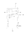
- the emergency operation valve A in the unload circuit B is displayed with a hydraulic symbol, as shown in FIG. 3B, and the pilot control circuit 8 communicates with the drain oil passage 3. .
- the pilot pressure is released from the relief valve 5, and the relief valve 5 is opened.
- the hydraulic oil enters an unloaded state in which it is sent from the supply oil passage 2 to the discharge oil passage 3 via the oil passage 7 (see FIG. 2). That is, since the hydraulic oil is not supplied to each hydraulic actuator in the unloaded state, each hydraulic actuator of the hydraulic working machine is not driven. This prevents accidents such as overwinding of the hook.
- valve closed state the state shown in FIG. 4A (hereinafter referred to as “valve closed state”).
- the pump side passage 17 and the tank side passage 18 are blocked by the pressure receiving portion 15.
- the valve body 13 of the emergency operation valve A may be pushed not only directly by hand but also via, for example, a machine.
- the valve closing state of the emergency operation valve A will be specifically described with reference to FIG. 4A.
- the pressure receiving portion 15 is located at the substantially central portion of the valve chamber 12.
- the pump side passage 17 communicates with the pressure receiving chamber 12a.
- the tank side passage 18 communicates with the spring chamber 12b. Therefore, when the emergency operation valve A is closed, the pump side passage 17 and the tank side passage 18 are not in communication.
- the emergency operation valve A in the unload circuit B is displayed with a hydraulic symbol as shown in FIG. 4B, and the pilot control circuit 8 is closed.
- the pilot pressure from the pilot circuit 5c is applied to the relief valve 5 in addition to the spring pressure, and the relief valve 5 is closed.
- the hydraulic oil is in an on-load state that is sent from the supply oil passage 2 to each hydraulic actuator. Thereby, the hook can be lowered and the boom can be retracted.
- FIG. 5A shows a state where the crane operator releases his / her hand from the valve body 13 and stops the pushing operation.
- the pump side passage 17 and the tank side passage 18 are shut off. To be kept. That is, the closed state of the emergency operation valve A is automatically maintained.
- a force (hereinafter referred to as a first pressing force) that the pressure receiving portion 15 is pressed in the second direction (downward in FIG. 5A) based on the pressure of the hydraulic oil in the pressure receiving chamber 12a.
- the force (hereinafter referred to as the second pressing force) by which the pressure receiving portion 15 is pressed in the first direction (upward in FIG. 5A) based on the elastic force of the spring 16 is balanced.
- the position of the pressure receiving part 15 is maintained at the position shown in FIG. 5A (that is, the second position).
- the predetermined condition is that the first pressing force and the second pressing force are balanced.
- the relief valve 5 When the state in which the pilot pressure of the pilot circuit 5c is added to the spring pressure of the spring 5b is held in the relief valve 5, the relief valve 5 is held in the closed state. That is, when viewed in the hydraulic circuit shown in FIG. 5B, the hydraulic oil is sent from the supply oil passage 2 to each hydraulic actuator (see arrow Xo in FIG. 5B), and the on-road state is maintained. Thereby, the crane operator can continue the lowering of the hook and the storing of the boom.
- the emergency operation valve A automatically returns from the closed state to the open state.
- automatic return of the emergency operation valve A will be described.
- the crane operator stops the engine of the vehicle when the boom retracting operation is completed.
- the hydraulic pump 1 stops rotating and hydraulic oil is no longer discharged from the hydraulic pump 1.
- the pressure is released from the pressure receiving chamber 12a of the emergency operation valve A, and the first pressing force becomes smaller than the second pressing force.
- the valve body 13 is displaced in the first direction (upward in FIG. 6B) by pressing the spring 16 (that is, the second pressing force).
- the pressure receiving part 15 is located in the 1st direction side (above FIG. 6B) rather than the pump side channel
- the emergency operation valve A automatically returns from the closed state to the open state.
- the unload circuit B is configured using the emergency operation valve A and the electromagnetic on-off valve 6.
- the unload circuit may be configured with only the emergency operation valve A.
- the emergency operation valve A according to the present embodiment is not limited to the overwinding prevention device, but is used in an unload circuit incorporated in another device (for example, an overload prevention device) having a function of stopping the operation of the crane. It can also be applied.
- the emergency operation valve A automatically returns from the closed state to the open state as described above. Specifically, in the valve-closed state shown in FIGS. 4A and 5A, when hydraulic oil is no longer supplied from the pump-side passage 17 to the pressure receiving chamber 12 a due to the drive stop of the hydraulic pump 1 or the like, the hydraulic oil in the pressure receiving chamber 12 a The pressure received by the pressure receiving portion 15 decreases. Then, the valve body 13 (specifically, the pressure receiving portion 15) is displaced from the valve-closed position by the spring 16 in the first direction (above FIGS. 4A and 5A).
- the pressure receiving portion 15 is displaced to the end portion in the first direction of the valve chamber 12 (the upper end portion in FIGS. 4A and 5B), and the pump side passage 17 and the tank side passage 18 communicate with each other via the spring chamber 12b. . That is, the emergency operation valve A returns to the valve open state shown in FIG. 6A without operating the valve body 13 by artificial force. As described above, the emergency operation valve A of the present embodiment automatically returns from the closed state to the open state, so that the emergency operation valve A is not forgotten to be released.
- the unload circuit B includes the emergency operation valve A as described above. For this reason, when the hydraulic pump 1 stops as the engine of the hydraulic working machine stops, the emergency operation valve A automatically returns from the closed state to the opened state. With such an automatic return of the emergency operation valve A, the hydraulic circuit incorporating the unload circuit B is switched from the on-load state to the unload state. Thus, according to the unload circuit B according to the present embodiment, since the forgetting to release the emergency operation valve A does not occur, the hydraulic working machine does not operate without permission and an accident can be prevented.
- a valve body inserted in a reciprocating manner, a spring that presses and biases the valve body toward one end of the valve chamber, a pump-side passage that is formed in the valve box and communicates with one end side of the valve chamber, and a valve chamber
- a tank side passage that communicates with the other end of the valve body, and the valve body has a pressure receiving portion that generates a force in a direction to push back the spring in response to the hydraulic oil pressure flowing in from the pump side passage.
- the pressure receiving part shuts off the pump side passage and the tank side passage, and even if the pressing operation is stopped, the state is maintained by the force generated by the pressure receiving part.
- the valve body is pushed back to one end by a spring, and the pump side passage and tank side A road can be configured so as to communicate.
- the pressure receiving portion receives the pressure of the hydraulic oil supplied from the pump side passage and the valve body compresses the spring. Since the state is maintained, the pump-side passage and the tank-side passage can be kept in a closed state even if the pressing operation is stopped. Further, while the pressure receiving portion of the valve body receives the hydraulic oil pressure, the pump side passage and the tank side passage can be automatically kept in a state of being shut off even if the artificial pushing operation is stopped.
- a relief valve in which an unload circuit in a hydraulic circuit of a hydraulic working machine is interposed between a supply oil passage connected to a pump and a discharge oil passage connected to a tank, and a relief valve
- the pilot pressure control valve that controls the supply and discharge of the pilot pressure may be used, and the pilot pressure control valve may be configured using the emergency operation valve of the reference example described above.
- the relief valve receives the pilot pressure and keeps the shut off state. Is supplied to the hydraulic working machine side, the hydraulic working machine operates normally. When the engine of the hydraulic working machine is stopped, the pump is also stopped and the pressure in the pump side passage disappears, so that the valve body of the emergency operation valve is energized by a spring and the pump side passage and the tank side passage To communicate. As described above, since the forgetting to return the emergency operation valve does not occur, the hydraulic working machine does not operate without permission and an accident can be prevented.
- the pilot pressure control valve is composed of an electromagnetic open / close valve and a manual open / close valve that are interposed in series with the pilot circuit
- the on-off valve may be the emergency operation valve of the reference example described above.
- the opening / closing of the relief valve is controlled by the electromagnetic opening / closing valve to prevent over-winding of the hook, but the electric system connected to the electromagnetic opening / closing valve is disconnected.
- the opening and closing of the relief valve is controlled by a manual emergency operation valve.
- the hydraulic working machine does not operate without permission, thus preventing an accident.
Landscapes
- Engineering & Computer Science (AREA)
- General Engineering & Computer Science (AREA)
- Mechanical Engineering (AREA)
- Physics & Mathematics (AREA)
- Fluid Mechanics (AREA)
- Analytical Chemistry (AREA)
- Chemical & Material Sciences (AREA)
- Automation & Control Theory (AREA)
- Fluid-Pressure Circuits (AREA)
- Mechanically-Actuated Valves (AREA)
- Component Parts Of Construction Machinery (AREA)
- Fluid-Driven Valves (AREA)
- Safety Valves (AREA)
Abstract
Description
ただし、特許文献1、2のアンロード回路は、盗難防止装置を構成するもので、フックの過巻き防止装置を構成するものではない。
そして、パイロット圧の給排を切換え制御する電磁開閉弁106が設けられている。
<1. 非常操作弁Aについて>
まず、図1に基づき、非常操作弁Aを説明する。なお、図1において、上方を一端方向とし、下方を他端方向として説明する。
つぎに、油圧作業機の一例であるトラック積載型クレーンのアンロード回路に非常操作弁Aを適用した実施形態を説明する。まず、図2に基づきアンロード回路Bまわりの回路構成を説明する。
供給油路2と排出油路3とには、操作バルブユニット20を介してクレーン用各アクチュエータが接続されている。図2には、ウインチモータ21、ブーム起伏シリンダ22およびブーム伸縮シリンダ23が図示されているが、他にも図示されていない各種油圧アクチュエータが存在する。上述のような基本構成を有する油圧回路において、供給油路2と排出油路3との間に、本発明のアンロード回路Bが設けられている。
以下、図3~図6を参照して、アンロード回路Bの動作について説明する。なお、以下の説明では、ソレノイド駆動電流が断線等の理由で電磁開閉弁6に通電されず、電磁開閉弁6が、バネにより開弁状態に保持されているものとする。
図3Aは非常操作弁Aを押し操作していない状態(換言すれば、開弁状態)を示している。非常操作弁Aの開弁状態において、受圧部15は、バネ16の押し付けにより弁室12内の第一方向の端部に位置している。また、ポンプ側通路17とタンク側通路18とは、矢印yで示すように連通している。
フックの過巻き防止後は、フックを巻き下げたり、ブームを格納位置に移動させたりしなければならない。このため、油圧回路全体をオンロード状態にする必要がある。そこでクレーン操作者は、図4Aに示すように、手で非常操作弁Aの弁体13を押し込む。具体的には、クレーン操作者は、弁棒14の一端(図3Aの上端)を第二方向(図3Aの下方)に押圧する。
ところで、フックの巻下げまたはブームの格納操作をするとき、クレーン操作者は、片方の手で非常操作弁Aを押した状態で、他方の手によりクレーンを操作する必要がある。
本実施形態に係る非常操作弁Aは、閉弁状態から開弁状態に自動復帰する。以下、非常操作弁Aの自動復帰について説明する。クレーン操作者は、ブームの格納操作が終了すると車両のエンジンを停止する。エンジンが停止すると、油圧ポンプ1の回転が止まり、油圧ポンプ1から作動油が吐出されなくなる。すると、非常操作弁Aの受圧室12aから圧力が抜け、上記第一押圧力が上記第二押圧力よりも小さくなる。この結果、図6Aに示す通り、バネ16の押し付け(つまり、上記第二押圧力)により弁体13が第一方向(図6Bの上方)に変位させられる。そして、受圧部15がポンプ側通路17よりも第一方向側(図6Bの上方)に位置して、ポンプ側通路17とタンク側通路18とが連通する。このようにして、非常操作弁Aは、閉弁状態から開弁状態へと自動復帰する。
また、本実施形態に係る非常用操作弁Aは、過巻き防止装置に限らず、クレーンの動作を停止させる機能を有する他の装置(例えば、過負荷防止装置など)に組み込まれるアンロード回路に適用することもできる。
本実施形態によれば、以下のような作用・効果を奏する。
まず、本実施形態に係る非常操作弁Aは、上述のように閉弁状態から開弁状態に自動復帰する。具体的には、図4A、5Aに示す閉弁状態において、油圧ポンプ1の駆動停止等の理由によりポンプ側通路17から受圧室12aに作動油が供給されなくなると、受圧室12a内の作動油から受圧部15が受ける圧力が減少する。すると、弁体13(具体的には、受圧部15)は、バネ16により閉弁状態の位置から第一方向(図4A、5Aの上方)に変位させられる。この結果、受圧部15が弁室12の第一方向の端部(図4A、5Bの上端部)に変位して、ポンプ側通路17とタンク側通路18とがばね室12bを介して連通する。すなわち、非常操作弁Aは、弁体13を人為的な力により操作することなく、図6Aに示す開弁状態に復帰する。以上のように、本実施形態の非常操作弁Aは、閉弁状態から開弁状態に自動復帰するため、非常操作弁Aの解除忘れが生じない。
非常操作弁の参考例として、油路を開弁状態と閉弁状態とに択一的に切換える非常操作弁を、弁箱と、弁箱内に形成された空洞状の弁室と、弁室内に往復動可能に挿入された弁体と、弁体を弁室の一端方向に押し付け付勢するバネと、弁箱に形成されており、弁室の一端側に通じるポンプ側通路と、弁室の他端側に通じるタンク側通路と、を備え、弁体は、ポンプ側通路から流入した作動油圧力を受けてバネを押し戻す方向の力を発生する受圧部を有しており、弁体をバネに抗して人為的に他端側に押し付けると受圧部がポンプ側通路とタンク側通路とを遮断するとともに押し付け操作をやめても受圧部により発生する力により状態が保持され、ポンプ側通路の圧力が失われた時はバネで弁体が一端側に押し戻されてポンプ側通路とタンク側通路とを連通させるように構成できる。
2 供給油路
3 排出油路
5 リリーフ弁
6 電磁開閉弁
8 パイロット制御回路
11 弁箱
12 弁室
13 弁体
14 弁棒
15 受圧部
16 バネ
17 ポンプ側通路
18 タンク側通路
A 非常操作弁
B アンロード回路
Claims (8)
- 開弁状態と閉弁状態とを択一的に切り換え可能な非常操作弁であって、
空洞状の弁室を有する弁箱と、
前記弁箱に形成され、前記弁室に供給される作動油の油路である第一油路と、
前記弁箱に形成され、前記弁室から排出される作動油の油路である第二油路と、
前記第一油路を前記第二油路に連通させる第一位置と前記第一油路を前記第二油路から遮断する第二位置との間を変位可能な状態で前記弁室に配置された受圧部と、
前記第二位置から前記第一位置に向かう方向に前記受圧部を付勢している弾性部材と、を備える、
非常操作弁。 - 前記弁室は、前記受圧部により第一室と第二室とに仕切られ、前記受圧部が前記第二位置にある状態で、前記第一油路が前記第一室に連通し、かつ、前記第二油路が前記第二室に連通している、請求項1に記載の非常操作弁。
- 前記受圧部が前記第一位置にある状態で、前記第一油路および前記第二油路が前記第二室に連通している、請求項2に記載の非常操作弁。
- 前記第一室内の作動油の油圧と前記弾性部材の弾性力とが所定の条件を満たす場合に、前記受圧部の位置が前記第二位置に維持される、請求項2または3に記載の非常操作弁。
- 前記第一室内の作動油の油圧と前記弾性部材の弾性力とが前記所定の条件を満たさなくなった場合に、前記受圧部が、前記弾性部材の弾性力に基づいて前記第二位置から前記第一位置に変位する、請求項4に記載の非常操作弁。
- 人為的な力により前記受圧部を前記第一位置から前記第二位置に変位させることができる、請求項1~5の何れか1項に記載の非常操作弁。
- 油圧作業機の油圧回路に用いられるアンロード回路であって、
ポンプにつながる供給油路とタンクにつながる排出油路との間に介装されたリリーフ弁と、
前記リリーフ弁へのパイロット圧の給排を制御するパイロット圧制御弁と、を備え、
前記パイロット圧制御弁は請求項1~6の何れか1項に記載の非常操作弁を含んで構成されている、
アンロード回路。 - 前記パイロット圧制御弁が、パイロット回路に直列に介装された電磁開閉弁と手動開閉弁とで構成されており、
前記手動開閉弁が前記非常操作弁である、
請求項7に記載のアンロード回路。
Priority Applications (3)
| Application Number | Priority Date | Filing Date | Title |
|---|---|---|---|
| JP2017541124A JP6219554B1 (ja) | 2016-04-06 | 2017-04-06 | アンロード回路 |
| CN201780020907.6A CN109073111B (zh) | 2016-04-06 | 2017-04-06 | 紧急操作阀以及卸载回路 |
| KR1020187026482A KR101942229B1 (ko) | 2016-04-06 | 2017-04-06 | 비상 조작 밸브 및 언로드 회로 |
Applications Claiming Priority (2)
| Application Number | Priority Date | Filing Date | Title |
|---|---|---|---|
| JP2016076332 | 2016-04-06 | ||
| JP2016-076332 | 2016-04-06 |
Publications (1)
| Publication Number | Publication Date |
|---|---|
| WO2017175820A1 true WO2017175820A1 (ja) | 2017-10-12 |
Family
ID=60001021
Family Applications (1)
| Application Number | Title | Priority Date | Filing Date |
|---|---|---|---|
| PCT/JP2017/014320 Ceased WO2017175820A1 (ja) | 2016-04-06 | 2017-04-06 | 非常操作弁およびアンロード回路 |
Country Status (4)
| Country | Link |
|---|---|
| JP (1) | JP6219554B1 (ja) |
| KR (1) | KR101942229B1 (ja) |
| CN (1) | CN109073111B (ja) |
| WO (1) | WO2017175820A1 (ja) |
Cited By (1)
| Publication number | Priority date | Publication date | Assignee | Title |
|---|---|---|---|---|
| CN112524325A (zh) * | 2020-11-30 | 2021-03-19 | 沧州润久智能仪表有限公司 | 一种应急阀 |
Families Citing this family (1)
| Publication number | Priority date | Publication date | Assignee | Title |
|---|---|---|---|---|
| JP7752578B2 (ja) * | 2022-06-17 | 2025-10-10 | 株式会社クボタ | 作業車 |
Citations (2)
| Publication number | Priority date | Publication date | Assignee | Title |
|---|---|---|---|---|
| JPS59186569U (ja) * | 1983-05-31 | 1984-12-11 | 三井精機工業株式会社 | 安全装置を具備した自己保持型開閉弁 |
| JP2010107009A (ja) * | 2008-10-31 | 2010-05-13 | Hitachi Constr Mach Co Ltd | 建設機械の油圧駆動装置 |
Family Cites Families (9)
| Publication number | Priority date | Publication date | Assignee | Title |
|---|---|---|---|---|
| US3495501A (en) * | 1968-06-04 | 1970-02-17 | Gen Electric | Valve operating and emergency closing mechanism |
| US5577532A (en) * | 1994-07-11 | 1996-11-26 | Palmer; Thomas W. | Valve actuator |
| JPH1113715A (ja) * | 1997-06-25 | 1999-01-22 | Kubota Corp | 緊急装置駆動用油圧ユニット |
| JP2008137454A (ja) | 2006-11-30 | 2008-06-19 | Furukawa Unic Corp | 作業機の盗難防止装置 |
| JP2009154740A (ja) | 2007-12-27 | 2009-07-16 | Tadano Ltd | 作業用車両の制御装置 |
| CN202023953U (zh) * | 2011-04-14 | 2011-11-02 | 东莞市骏颖机械制造有限公司 | 一种用于聚氨酯高压发泡机的高低压切换阀 |
| US9651067B2 (en) * | 2012-07-31 | 2017-05-16 | Caterpillar Inc. | Hydraulic system with a dynamic seal |
| CN204805220U (zh) * | 2015-05-27 | 2015-11-25 | 上海朝田实业有限公司 | 一种活塞式超低压溢流阀 |
| CN204677838U (zh) * | 2015-06-09 | 2015-09-30 | 武汉东江阀业制造有限公司 | 超高压直动式瞬间平衡阀 |
-
2017
- 2017-04-06 JP JP2017541124A patent/JP6219554B1/ja active Active
- 2017-04-06 KR KR1020187026482A patent/KR101942229B1/ko active Active
- 2017-04-06 CN CN201780020907.6A patent/CN109073111B/zh active Active
- 2017-04-06 WO PCT/JP2017/014320 patent/WO2017175820A1/ja not_active Ceased
Patent Citations (2)
| Publication number | Priority date | Publication date | Assignee | Title |
|---|---|---|---|---|
| JPS59186569U (ja) * | 1983-05-31 | 1984-12-11 | 三井精機工業株式会社 | 安全装置を具備した自己保持型開閉弁 |
| JP2010107009A (ja) * | 2008-10-31 | 2010-05-13 | Hitachi Constr Mach Co Ltd | 建設機械の油圧駆動装置 |
Cited By (1)
| Publication number | Priority date | Publication date | Assignee | Title |
|---|---|---|---|---|
| CN112524325A (zh) * | 2020-11-30 | 2021-03-19 | 沧州润久智能仪表有限公司 | 一种应急阀 |
Also Published As
| Publication number | Publication date |
|---|---|
| CN109073111B (zh) | 2019-12-13 |
| JP6219554B1 (ja) | 2017-10-25 |
| KR101942229B1 (ko) | 2019-01-24 |
| JPWO2017175820A1 (ja) | 2018-04-12 |
| CN109073111A (zh) | 2018-12-21 |
| KR20180108837A (ko) | 2018-10-04 |
Similar Documents
| Publication | Publication Date | Title |
|---|---|---|
| KR100956999B1 (ko) | 외부 파일럿 작동형 홀딩밸브를 갖는 유압회로 | |
| CN107250563B (zh) | 用于建筑机械的流量控制阀 | |
| US8322797B2 (en) | Hydraulic device for actuating the braking of work vehicles and the like | |
| CN109416060B (zh) | 缸驱动装置 | |
| JP6159629B2 (ja) | 流体圧制御装置 | |
| JP6219554B1 (ja) | アンロード回路 | |
| JP6606426B2 (ja) | バルブ装置 | |
| US20150013804A1 (en) | Flow responsive latch for holding a spool valve in an open position | |
| JP6504656B2 (ja) | 制御弁及びそれを備える流体圧制御装置 | |
| US9958066B2 (en) | Range switching device | |
| US8869834B2 (en) | Pneumatic control device operated by one hand | |
| JP2017223236A (ja) | 切換弁および薪割装置 | |
| JP2016223498A (ja) | 流体制御装置 | |
| KR102858701B1 (ko) | 윤활 펌프 장치 | |
| JP6161416B2 (ja) | 油圧制御装置 | |
| JP6982517B2 (ja) | 流体圧制御装置 | |
| JP6217868B2 (ja) | コントロールバルブ | |
| KR102155487B1 (ko) | 굴삭기 작업장치 제어용 유압 시스템의 홀딩 밸브 및 이를 구비하는 굴삭기 작업장치 제어용 유압 시스템 | |
| JP7083605B2 (ja) | パイロット油制御回路 | |
| EP3138964A1 (en) | Flow control valve for construction equipment | |
| CN104329322A (zh) | 用于静液压驱动系统的释放阀 |
Legal Events
| Date | Code | Title | Description |
|---|---|---|---|
| ENP | Entry into the national phase |
Ref document number: 2017541124 Country of ref document: JP Kind code of ref document: A |
|
| ENP | Entry into the national phase |
Ref document number: 20187026482 Country of ref document: KR Kind code of ref document: A |
|
| WWE | Wipo information: entry into national phase |
Ref document number: 1020187026482 Country of ref document: KR |
|
| NENP | Non-entry into the national phase |
Ref country code: DE |
|
| 121 | Ep: the epo has been informed by wipo that ep was designated in this application |
Ref document number: 17779198 Country of ref document: EP Kind code of ref document: A1 |
|
| 122 | Ep: pct application non-entry in european phase |
Ref document number: 17779198 Country of ref document: EP Kind code of ref document: A1 |