WO2017175293A1 - シャフトカップリングアセンブリ並びにシャフトカップリングアセンブリによって二つのシャフトを連結する方法及び保守方法 - Google Patents
シャフトカップリングアセンブリ並びにシャフトカップリングアセンブリによって二つのシャフトを連結する方法及び保守方法 Download PDFInfo
- Publication number
- WO2017175293A1 WO2017175293A1 PCT/JP2016/061075 JP2016061075W WO2017175293A1 WO 2017175293 A1 WO2017175293 A1 WO 2017175293A1 JP 2016061075 W JP2016061075 W JP 2016061075W WO 2017175293 A1 WO2017175293 A1 WO 2017175293A1
- Authority
- WO
- WIPO (PCT)
- Prior art keywords
- coupling
- hub
- shaft
- notch
- yoke
- Prior art date
Links
Images


Classifications
-
- F—MECHANICAL ENGINEERING; LIGHTING; HEATING; WEAPONS; BLASTING
- F16—ENGINEERING ELEMENTS AND UNITS; GENERAL MEASURES FOR PRODUCING AND MAINTAINING EFFECTIVE FUNCTIONING OF MACHINES OR INSTALLATIONS; THERMAL INSULATION IN GENERAL
- F16D—COUPLINGS FOR TRANSMITTING ROTATION; CLUTCHES; BRAKES
- F16D3/00—Yielding couplings, i.e. with means permitting movement between the connected parts during the drive
- F16D3/02—Yielding couplings, i.e. with means permitting movement between the connected parts during the drive adapted to specific functions
- F16D3/04—Yielding couplings, i.e. with means permitting movement between the connected parts during the drive adapted to specific functions specially adapted to allow radial displacement, e.g. Oldham couplings
Definitions
- the present invention relates to a shaft coupling assembly that can cope with misalignment, a method for connecting two shafts by the shaft coupling assembly, and a maintenance method.
- both rotation shafts are spaced apart and connected by a coupling.
- misalignment usually classified into eccentricity, declination, and end play occurs between two shafts of the output rotation shaft of the engine or motor and the input rotation shaft of the pump.
- a part of the structure includes a flexible structure that can absorb misalignment.
- Patent Document 1 discloses a rigid coupling device, but includes a flexible structure in which a slit perpendicular to an axis is inserted (Patent Document 1, Claims and FIG. 1).
- Patent Document 2 discloses a shaft coupling that has torsional rigidity and allows misalignment, but partially includes a flexible structure called a torsion spring mechanism.
- the torsion spring mechanism can “pivot and move in the axial direction to absorb slight misalignment” (paragraph 0048, lines 1 to 4 of Patent Document 2), “preload is applied” (Paragraph 0050, third line of Patent Document 2).
- U.S. Pat. No. 6,057,089 provides a method of connecting two shafts by a shaft coupling assembly comprising a rigid member including a sleeve (FIG. 1 of U.S. Pat. It does not provide a way to connect the two shafts.
- Patent Document 4 Japanese Patent Publication No. 2006-3779918
- This invention is an invention composed only of a rigid structure and does not include a flexible structure, but even if misalignment adjustment can be adjusted at the initial stage of installation, in particular, misalignment due to aging or wear of the support structure, or comparison It is difficult to absorb the misalignment caused by the dynamic deformation of the support structure in the case of mounting on a ship placed under a flexible structure. For this reason, Patent Document 4 seems to have a separate wear detection means so that secular change can be observed (Claim 1 of Patent Document 4). This makes it possible to indirectly understand that it is difficult to assemble a coupling that is composed only of a rigid structure and does not include a flexible structure, and to realize the installation and easy maintenance of a rotating machine. The inventor of the present application has tackled this problem from the front in order to achieve both a coupling configuration consisting entirely of a rigid structure and misalignment absorption.
- Non-Patent Document 1 uses a laser measuring instrument and computer-aided software in cooperation to determine the amount of misalignment. Disclose technology for precise digital measurement.
- Non-Patent Document 1 even if misalignment is measured by modernization techniques, correction of this misalignment can be done by adjusting the position and inclination of the mounting pedestal and inserting spacers into the pedestal. Usually, there is no choice but to do physical and mechanical care such as adjusting the thickness. Surprisingly, in many cases, alignment adjustment methods must rely on primitive human machine work such as adjusting the position of the mounting pedestal, inserting spacers into the pedestal, experience and manual intuition. It is.
- any member has to be made a flexible structure after all.
- One approach of flexible structure is to have a thin structure part in part like a slit and include a soft structure, partly a spring structure part to include a soft structure, or like a flexible coupling, In general, a bellows-like shape is included, or a flexible material such as an elastic material or rubber is used as a material for the connection portion to include a flexible structure.
- Patent Document 5 is a detachable coupling, and “the present invention can shorten the axial length as much as possible, and can be used for a joint of eccentricity, declination, and end play. "Providing a propeller shaft structure that can absorb all of the three disadvantageous misalignment elements and that is easy to attach and detach to and from the input / output shaft, and that is easy to assemble and maintain" (paragraph 0004 of Patent Document 5).
- a main object of the present invention is a shaft coupling assembly having a novel structure that allows high torque transmission and is easy to assemble and disassemble in a compact space, and has an eccentric, declination, and end play cup.
- the object is to provide a shaft coupling assembly that is capable of absorbing all three misalignment elements unavoidable for the ring. That is, (1) It is inconvenient for coupling of eccentricity, declination, and end play and can absorb all three misalignment elements that are generally inevitable. It is easy (3) It is possible to provide a coupling with a large common torque It is an object of the present invention to provide a shaft coupling assembly and a method for connecting two shafts by the shaft coupling assembly and a maintenance method.
- the present invention that has solved the above problems is as follows.
- ⁇ Invention of Claim 1> The following parts connecting the two torque transmission shafts: A first hub that is matable with the first shaft; A second hub that is matable with the second shaft; With a coupling disc; Two sets of coupling blocks, each of which is engageable or connectable to the hub and the coupling disk; and an outer periphery of any one of the two members of the hub or the coupling disk
- the surface is provided with a total of two pairs of notches that are opposed to each other by 180 ° along the axial direction with the shaft core interposed therebetween, and covers the outer peripheral surface of the member including the notches.
- a sleeve capable of sealing the notch with respect to the open space on the outer peripheral side of the member;
- a shaft coupling assembly comprising: The notch is a pair of notches along the axial direction facing the outer periphery of only one of the two components of the hub or the coupling disk, with the shaft core sandwiched by 180 °.
- the remaining two types of members that do not have the notch portion are shaft couplings that are 180 ° opposite each other and have an insert hole along the axial direction.
- the method of connecting two shafts by an assembly includes the following steps: A shaft alignment step of roughly aligning the first shaft and the second shaft in advance; A first hub connecting step of inserting the first shaft into the first hub and coupling both members; A second hub connecting step of inserting the second shaft into the second hub and coupling both members; Coupling the first hub and the second hub, the following steps: The coupling block is engaged with the member having the notch portion at the notch portion, and the coupling block engaging and connecting step of connecting both members; and the coupling block does not have the notch portion.
- a coupling block constraining connection stage connected and constrained to the insert hole of the member; And a sleeve step of sealing the coupling block engaged with the notch after the assembly by the sleeve covering the notch to the notch. Connecting two shafts by a shaft coupling assembly.
- the notch used in the present invention is an open notch, which forms an open space in the radial direction of the member having the notch and can be taken in and out for engagement from the open to the notch.
- the shaft coupling assembly used in the present method uses a sleeve member that covers a member having a notch, and the coupling block can be sealed in the notch that is covered with the sleeve during assembly.
- the both ends of the coupling block are sandwiched between the coupling disk surface and the flange end surface of the hub, and after assembly of the shaft coupling assembly, as a whole, are shielded from the external environment such as dust, moisture and salt.
- a new shaft coupling assembly that allows transmission of high torque while being easy to assemble and disassemble in a compact space, and is inevitable for misalignment, declination and end play coupling
- a method of connecting two shafts by a shaft coupling assembly that substantially provides a shaft coupling assembly capable of absorbing all three elements.
- the coupling step includes connecting means (1) and (2) described below, (1) One set of notch portions that can engage the coupling block in the axial direction on the outer peripheral surface that faces the 180 ° angle with the shaft core sandwiched between the first hub and the second hub. (2) Two sets of connecting means are used on the disk surface opposite to each other at 180 ° with the insertion hole into which the coupling block can be inserted along the axial direction sandwiching the disk center of the coupling disk.
- a coupling process comprising: The sleeve is a separate sleeve that covers the outer circumferences of the first hub and the second hub, and the sleeve covers the notch, and after the sleeve is assembled, the notch is an open space on the outer circumference side of the hub.
- a first yoke configuration in which the ring block is movable in the axial direction and misalignment of the end play is allowed; and a second yoke substantially formed by the second hub and the coupling block engaged therewith The coupling block is movable in the radial direction within the notch, and the yoke is misaligned.
- the coupling block In the notch, the coupling block can be tilted in the axial direction so that misalignment of the deflection angle of the yoke can be allowed, and in the notch, the coupling block is Second yoke configuration that can move in the axial direction and also allow misalignment of the end play;
- the first yoke and the second yoke are configured to allow misalignment of eccentricity and declination of each yoke, and in total, allow misalignment of decentering and declination in all directions.
- the method of connecting two shafts by the shaft coupling assembly of the present invention according to claim 2 is easy to couple, and the shafts can be easily connected.
- the present invention allows for eccentricity, declination and end play. Even if the shaft coupling assembly of the present invention is retrofitted after both shafts are installed, misalignment adjustment work is not necessarily required for connection with the shaft coupling assembly.
- the notch of the first hub is one of the two sets of coupling blocks. Engage with one end of a pair of coupling blocks to form a virtual first yoke after assembly, and the other end engages with a pair of opposing insert holes in the coupling disk And allowing misalignment as the virtual yoke integral, and A notch portion of the second hub engages with one end portion of the remaining coupling block of the two sets of coupling blocks to form a second virtual yoke after assembly.
- This yoke is a method of connecting two shafts by a shaft coupling assembly which is connected to a pair of opposed insert holes of the coupling disk at the other end and allows misalignment as a virtual yoke integral.
- a first hub that can be fitted to a first shaft that has a pair of notches along the axial direction with a shaft core sandwiched between the outer periphery and 180 °; A first sleeve covering the hub from the first shaft side; A second hub that can be fitted to a second shaft that has a pair of notches along the axial direction with a shaft core sandwiched between the outer periphery and 180 °; A second sleeve covering the hub from the second shaft side; A coupling disk having two pairs of insert holes that are 180 ° opposite to each other across the center of the disk and that extend along the axial direction; and two sets of coupling blocks that form two pairs
- the eccentricity and the deflection angle included in the present invention are included.
- the end play permission function eliminates the need for including misalignment adjustment work as an
- the first sleeve seals the coupling block engaged with the notch of the first hub in the notch, and the second sleeve is engaged with the notch of the second hub.
- the coupling block is sealed in the notch, and the coupling block is not separated from the engaged state.
- the coupling step includes connecting means (3) and (4) described below, (3) Two sets of notches capable of engaging the coupling block along the axial direction on the outer peripheral surface facing the 180 ° across the disk central axis of the coupling disk.
- a pair of connecting means are used on the hub flange surfaces facing each other by sandwiching the insert holes that can be inserted along the axis of each of the first hub and the second hub, and the coupling process includes the following steps: Each stage: A coupling block engaging and connecting step of engaging the outer surface of two sets of the coupling blocks with the notch on the coupling disk; A coupling block first hub constraining connection step, wherein the first hub is screwed with a bolt for inserting an end face of the set of coupling blocks into the insert hole; and the remaining set of the second hub A coupling block second hub restraint connection stage in which an end face of the coupling block is screwed with a bolt inserted into the insert hole; A coupling process comprising: The sleeve is a sleeve that covers an outer periphery of the coupling disk, and the notch is sealed from an open space on the outer peripheral side of the coupling disk after assembly by the sleeve that covers the notch.
- the coupling block can be tilted in the axial direction to allow misalignment of the deflection angle of the yoke, and in the notch, the coupling block has a shaft.
- a first yoke configuration that is movable in the direction and also allows end play misalignment; and a second yoke substantially formed by the second hub and the coupling block, in the notch
- the coupling block can be moved in the radial direction, and misalignment of the eccentricity of the yoke can be allowed.
- the coupling block In the notch, the coupling block can be tilted in the axial direction, so that misalignment of the deflection angle of the yoke can be allowed, and in the notch, the coupling block can be moved in the axial direction.
- Second yoke configuration that allows for play misalignment;
- the first yoke and the second yoke are configured so that the yokes can integrally accept eccentricity and declination misalignment, and in total, allow misalignment of eccentricity and declination in all directions.
- the coupling can be easily assembled and the shaft can be easily connected.
- the present invention allows for eccentricity, declination and end play. Even if the shaft coupling assembly of the present invention is retrofitted after both shafts are installed, misalignment adjustment work is not necessarily required for connection with the shaft coupling assembly.
- the end face of the coupling block as a set on the first hub.
- the first yoke is formed with a bolt inserted into the insert hole, and the coupling block is engaged with a pair of opposed notches of the coupling disk at the side surface, and the virtual Allows misalignment of the yoke, and
- the end face of the remaining set of the coupling block is screwed to the second hub with a bolt inserted into the insert hole to form a second imaginary yoke, and the second yoke is a side portion of the second hub.
- two shafts are connected by a shaft coupling assembly that engages with a pair of opposed notches of a coupling disk and allows misalignment of the virtual yoke.
- the end play permission function eliminates the need for
- the sleeve seals the coupling block engaged with the notch of the coupling disk in the notch, and the second sleeve is the cup engaged with the notch of the second hub.
- the ring block is sealed in the notch, and the coupling block does not leave the engaged state.
- the torque transmission structure is as follows: A first hub that can be fitted to a first shaft that has a pair of notches along the axial direction with a shaft core sandwiched between the outer periphery and 180 °; A second hub that can be fitted to a second shaft that has a pair of notches along the axial direction with a shaft core sandwiched between the outer periphery and 180 °; A coupling disk having two pairs of insert holes that are 180 ° opposite to each other across the center of the disk and extend along the axial direction; and two sets of coupling blocks, each having two pairs
- a shaft coupling assembly comprising: The notch portion of the first hub engages with one end portion of a pair of coupling blocks of the two sets of the two sets, and a first yoke can be formed after assembly
- the coupling block engages from the disk surface side of one end to a pair of opposing insert holes of the coupling disk at the other end, and allows misalignment as the first yoke integrated with the other, and
- the notch portion of the second hub engages with one end portion of the remaining pair of coupling blocks of the two sets of coupling blocks so that a second yoke can be formed after assembly.
- the coupling block is movable in the axial direction within the notch, After assembly, the first sleeve seals the coupling block engaged with the notch portion of the first hub in the notch portion, and the second sleeve seals the coupling block to the notch portion.
- a shaft coupling assembly After assembly, the first sleeve seals the coupling block engaged with the notch portion of the first hub in the notch portion, and the second sleeve seals the coupling block to the notch portion.
- one set is defined as two, and each coupling block corresponds to one hub.
- the hub that can be fitted to the first shaft is the first hub and the other is the second hub, but the external shapes may be the same.
- the hub is formed with a pair of cutout portions along the axial direction so as to face the outer peripheral surface with the shaft core sandwiched by 180 °.
- a coupling block is engaged with the notch.
- One end of one coupling block is accommodated in one notch.
- a coupling disk is disposed between the hubs.
- the coupling disk is formed with four insert holes, and two insert holes that are opposed to each other by 180 ° across the center of the disk are engaged with the same hub. Two coupling blocks are engaged.
- Each hub is engaged with the coupling block from the surfaces facing each other.
- the two coupling blocks engage with the hub on one side and are arranged like a first yoke and a second yoke.
- “so” means that the sleeve that covers the hub is assembled, sealed by being surrounded by the notch of the sleeve and the hub, and the yoke is configured only after assembly. expressing.
- a notch portion of the first hub engages to form a coupling block like a first yoke, and the coupling block sandwiches the axis of the coupling disc between the sleeve and the coupling disc end.
- the allowable misalignment direction of one yoke is the X-axis direction
- the other yoke surface crosses the X-axis in accordance with the insert hole of the coupling disk after assembly with one yoke surface, and one of them is the Y-axis direction.
- misalignment allowed on the other yoke surface is also allowed in the Y-axis direction, and misalignment in an XY axis constituting plane, that is, in any direction is allowed by both yokes.
- the coupling block can be moved in the axial direction within the notch, and misalignment of the end play is allowed within the notch in relation to the coupling block.
- end play is allowed by the misalignment allowed in the first yoke, the misalignment allowed in the second yoke and the end play, and the sliding of the coupling block in the insert hole. Misalignment, eccentricity, declination, and end play are acceptable.
- the torque transmission structure is as follows: A first hub that can be fitted to a first shaft having a pair of insert holes that are 180 ° opposite to each other with an axial center sandwiched between them; A second hub that can be fitted to a second shaft having a pair of insert holes that are 180 ° opposite to each other with an axial center sandwiched between them; A coupling disk having two pairs of notch portions along the axial direction with the disk center sandwiched between the outer peripheral surface and 180 °; A sleeve covering the notch of the coupling disk; and two sets of coupling blocks, each of which is a set of two pieces; A shaft coupling assembly comprising: The end face of one coupling block of the two coupling blocks that penetrates the insert hole of the first hub and sets the two is screwed and connected by bolts to the second after the assembly.
- a yoke can be formed, and the coupling block engages with the pair of opposed notches of the coupling disk on the outer surface, and allows misalignment of the first yoke; and Through the insert hole of the second hub, the end face of the remaining coupling block of the two sets of coupling blocks is screwed and connected with bolts to form a second yoke after assembly.
- the coupling block engages with the pair of opposed notches of the coupling disk on the outer surface, and allows misalignment of the second yoke.
- the sleeve is a shaft coupling assembly that seals the coupling block to the notch.
- each coupling block corresponds to one hub.
- the hub that can be fitted to the first shaft is the first hub and the other is the second hub, but the external shapes may be the same.
- a pair of insert holes are formed along the axial direction so as to be opposed to each other by 180 ° with the shaft core interposed therebetween.
- the coupling block is fixedly connected to the coupling block with screws by the bolts penetrating the insert hole. When the coupling block is fastened to the first hub, the first yoke is formed.
- One coupling block is accommodated and engaged with one notch of a pair of notches formed along the axial direction so as to face the outer peripheral surface of the coupling disk at 180 ° across the center of the disk.
- Coupling discs can be placed between the hubs, but the coupling disc has two sets of notches, and a total of four notches are formed.
- Two coupling blocks fastened to the same hub are engaged with a pair of notches that are 180 ° opposite to each other with the disk center interposed therebetween and extend in the axial direction. After assembly, each hub is engaged with the coupling disk at the flange surfaces on the opposite sides.
- the two coupling blocks are screwed together with bolts penetrating the flange surface of the hub and the flange hole on one side to form a first yoke and a second yoke.
- the coupling block of the first yoke formed by the coupling block that is screwed and connected through the insert hole of the first hub engages with a pair of notches facing each other across the axis of the coupling disk
- the sleeve covering the coupling disk it is sealed in the space formed by the notch and the sleeve, allowing for eccentricity and declination of the yoke and misalignment of the end play, and the notch depth direction
- the inclination and movement of the outer yoke are restricted, if the misalignment permissible direction of one yoke is the X-axis misalignment permissible direction, the other yoke surface becomes the insert hole of the coupling disk after assembly.
- the shaft coupling assembly can be constituted by only a rigid member.
- the present invention provides all types of misalignment, eccentricity and declination based on misalignment allowed in the first yoke, misalignment allowed in the second yoke, and sliding of the coupling block in the insert hole. And a shaft coupling assembly that allows end play. Compared to a universal joint, axial misalignment and end play are also realized with the above configuration, and this is a shaft coupling assembly that provides space saving, simpler configuration, and lower cost.
- a flexible coupling member, thin plate, spring member, or other flexible structural member is not required, and the shaft coupling assembly is composed only of a rigid torque transmission structure component, and can provide a high torque function.
- a flexible member such as a flexible member, a thin plate, or a spring member is not required, but even if a viscoelastic member or engineering plastic having a certain degree of rigidity is used, high torque transmission can be achieved to some extent.
- the notch may have any shape that allows the yoke to move in the radial direction, and the insert hole only needs to allow the axial movement. If the notch is a notch with a substantially rectangular cross section due to the combination of the shape of the coupling block, and the insert hole is a substantially circular hole, the coupling block is a cylinder with a diameter smaller than its side length in the honest cuboid A combination of coupling blocks having a combination of the above is advantageous in terms of positioning convenience and processing, which is preferable. This configuration is simple and convenient for assembly and maintenance.
- a method of maintaining a shaft coupling assembly including two shafts connected in a manner of connecting two shafts by the shaft coupling assembly of claim 2 includes the following steps: Removing the sleeve from the hub to expose the notch; After the, A method for maintaining a shaft coupling assembly, comprising the step of replacing the coupling block without disassembling a shaft coupling assembly member other than the sleeve.
- a method of maintaining a shaft coupling assembly including two shafts connected in a manner of connecting two shafts by the shaft coupling assembly of claim 3 includes the following steps: Removing the sleeve from the coupling disc to expose the notch; After the, A method for maintaining a shaft coupling assembly, comprising the step of replacing the coupling block without disassembling a shaft coupling assembly member other than the sleeve.
- the shaft coupling assembly method of the present invention provides a method for easily maintaining the coupling. This is because each member, which is a constituent means of the present invention, provides a coupling that allows for eccentricity, declination, and end play when assembled. Even if the shaft coupling assembly of the present invention is retrofitted after both shafts are installed, misalignment adjustment work is not necessarily required for connection with the shaft coupling assembly.
- ⁇ Invention of Claim 12> The method according to any one of claims 1 to 3, 10 or 11, wherein the coupling disk is formed by stacking a plurality of disks. (Function and effect)
- the present invention provides a method that makes it easier to assemble / maintain the shaft coupling assembly even when the separation between the first shaft and the second shaft is smaller.
- ⁇ Invention of Claim 13> The shaft coupling assembly according to claim 4 or 5, wherein the coupling disk is formed by stacking a plurality of disks.
- the present invention makes it easier to assemble the shaft coupling assembly even when the separation between the first shaft and the second shaft is smaller.
- a shaft coupling assembly having a novel structure that enables transmission of high torque and is easy to assemble and disassemble in a compact space.
- An object of the present invention is to substantially provide a shaft coupling assembly, an assembly method thereof, and a maintenance method capable of absorbing all three misalignment elements which are inconvenient and unavoidable for the coupling. That is, (1) Capable of absorbing all three misalignment elements that are inconvenient for coupling, including eccentricity, declination, and end play. (2) Easy to attach and detach the coupling even when the shafts on both sides are installed and fixed. (3) A coupling with a large service torque can be provided (4) Provided is a shaft coupling assembly having a new structure that is easy to assemble and disassemble in a compact space.
- 1 is an exploded perspective schematic view of a shaft coupling assembly 1 which is an embodiment of a shaft coupling assembly according to the present invention.
- 1 is a schematic perspective view of an assembled state of a shaft coupling assembly 1 which is an embodiment of a shaft coupling assembly according to the present invention.
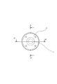
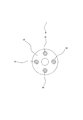
- It is a front schematic diagram of the assembly state of the shaft coupling assembly 1 which is one Embodiment of the shaft coupling assembly which concerns on this invention.
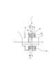
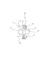
- It is a vertical longitudinal cross-sectional schematic diagram of the assembly state of the shaft coupling assembly 1 which is one Embodiment of the shaft coupling assembly which concerns on this invention.
- It is a horizontal longitudinal cross-sectional schematic diagram of the assembly state of the shaft coupling assembly 1 which is one Embodiment of the shaft coupling assembly which concerns on this invention.
- 1 is a cross-sectional schematic diagram of a first hub 11 part in an assembled state of a shaft coupling assembly 1 which is an embodiment of a shaft coupling assembly according to the present invention. It is a 2nd hub 21 part cross-sectional schematic diagram of the assembly state of the shaft coupling assembly 1 which is one Embodiment of the shaft coupling assembly which concerns on this invention. 1 is a schematic cross-sectional view of a coupling disk 50 part in an assembled state of a shaft coupling assembly 1 which is an embodiment of a shaft coupling assembly according to the present invention. It is a disassembled perspective schematic diagram of the shaft coupling assembly 100 which is other embodiment of the shaft coupling assembly which concerns on this invention.
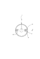
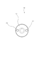
- FIG. 1 is a cross-sectional schematic diagram of a coupling disk 150 part in an assembled state of a shaft coupling assembly 100 which is an embodiment of a shaft coupling assembly according to the present invention.
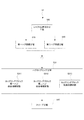
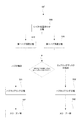
- 3 is a step basic flowchart S0 of a method for connecting two shafts by a shaft coupling assembly according to the present invention;
- 4 is a step flowchart S1 according to an embodiment of a method for connecting two shafts by a shaft coupling assembly according to the present invention.
- 6 is a step flowchart S2 according to another embodiment of a method for connecting two shafts by a shaft coupling assembly according to the present invention.
- 4 is a step integration flowchart S0 ′ of a method for connecting two shafts by a shaft coupling assembly according to the present invention;
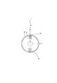
- FIG. 1 shows an exploded perspective schematic view of one embodiment of a shaft coupling assembly according to the present invention
- FIG. 2 shows a perspective schematic view of an assembled state of one embodiment of a shaft coupling assembly according to the present invention
- FIG. 3 is a schematic front view of an assembled state of an embodiment of a shaft coupling assembly according to the present invention
- FIG. 4 is a schematic vertical longitudinal sectional view of an assembled state of an embodiment of a shaft coupling assembly according to the present invention.
- FIG. 5 shows a schematic diagram of a horizontal longitudinal section of an embodiment of a shaft coupling assembly according to the present invention
- FIG. 6 shows an assembly of an embodiment of a shaft coupling assembly according to the present invention.
- FIG. 7 is a schematic cross-sectional view of the first hub portion in a state
- FIG. 8 is a schematic cross-sectional view
- FIG. 8 is a schematic cross-sectional view of a coupling disk 50 part in an assembled state of the shaft coupling assembly 1 which is an embodiment of the shaft coupling assembly according to the present invention.
- the schematic cross-sectional view only the cross section of the coupling block is hatched.
- FIG. 15 shows a basic step flow chart S0 of a method of connecting two shafts by a shaft coupling assembly according to the present invention
- FIG. 16 shows a method coupling by the shaft coupling assembly according to the present invention
- FIG. 17 shows a step flowchart S1 according to an embodiment of a method for connecting two shafts
- FIG. 17 shows a step flowchart S2 according to another embodiment of a method for connecting two shafts by a shaft coupling assembly according to the present invention
- FIG. 18 shows a step integration flow chart S0 ′ of a method for connecting two shafts by a shaft coupling assembly according to the present invention.
- the hub coupling process includes a coupling block engagement and connection stage (S301) and a coupling block restraint / continuation stage (S302).
- Sleeve process (S40) including.
- the shaft coupling assembly according to the embodiment of the present invention used in the step basic flowchart S0 will be outlined.
- a shaft coupling assembly includes: The following parts connecting the two torque transmission shafts: A first hub that is matable with the first shaft; A second hub that is matable with the second shaft; And a pair of notches along the axial direction AX across the outer periphery of any one of the two members of the hub or the coupling disc with the shaft core sandwiched 180 ° therebetween. Including a sleeve that covers the outer peripheral surface of the member including the notch, and can seal the notch from the open space on the outer peripheral side of the member.
- the other kind of member that does not have the notch is a shaft coupling assembly that is a member that has an insert hole along the axial direction with 180 degrees facing the shaft core.
- FIG. 1 is an exploded perspective schematic view of an embodiment of a shaft coupling assembly according to the present invention
- FIG. 2 is a schematic perspective view of an assembled state of an embodiment of a shaft coupling assembly according to the present invention
- FIG. 3 is according to the present invention.
- FIG. 4 is a schematic front view of an assembled state of an embodiment of a shaft coupling assembly
- FIG. 4 is a schematic vertical vertical sectional view of an assembled state of an embodiment of a shaft coupling assembly according to the present invention
- FIG. 5 is a shaft coupling assembly according to the present invention.
- FIG. 6 is a schematic diagram of a horizontal longitudinal section in an assembled state of an embodiment of the present invention
- FIG. 6 is a schematic diagram of a transverse section of a first hub portion in an assembled state of an embodiment of a shaft coupling assembly according to the present invention
- FIG. FIG. 8 is a schematic cross-sectional view of the second hub portion in an assembled state according to an embodiment of the assembly
- FIG. Referring to the coupling disc 50 parts cross-sectional schematic view of the assembled state of the shaft coupling assembly 1 according to an embodiment of Li, detailing an embodiment of a shaft coupling assembly 1 according to the present invention.
- a shaft coupling assembly 1 includes: The following members connecting the two torque transmission shafts 10, 20: A first hub 11 that can be fitted to the first shaft 10; A second hub 21 that can be fitted to the second shaft 20; The first shaft 10 is fitted into the inner hole of the first hub 11 by a key, and the second shaft 20 is fitted into the inner hole of the first hub 21 by, for example, a key.
- the torque transmission structure is as follows: A first hub 11 that has a pair of notches 12 and 13 along the axial direction AX and is opposed to the outer peripheral surface by sandwiching the shaft core 4 at 180 °; A second hub 21 that has a pair of notches 22 and 23 along the axial direction AX and that faces the outer circumferential surface with the shaft core 2 sandwiched by 180 ° and that can be fitted to the second shaft 20; Two pairs of insert discs with two pairs of insert holes along the axial direction AX across the disc center 3 with 180 ° facing each other, (30, 31) (40, 41); and two sets of two Coupling blocks (32, 33) (42, 43); In addition, the following: A first sleeve 15 covering the first hub 11 from the first shaft 10 side to cover the notches 12 and 13; and a second hub 21 from the second shaft 20 side to the notches 22 and 23.
- a second sleeve 25 covering A shaft coupling assembly 1 comprising: One end of a set of coupling blocks (32, 33) out of two sets of coupling blocks 32, 33, 42, 43 in which the notches 12 and 13 of the first hub 11 are the two sets.
- the first yoke 34 can be formed after assembly by engaging with the portion, and the coupling blocks 32 and 33 are connected at one end to the pair of insert holes 30 and 31 facing the coupling disk 50 at the other end. Joining from the disk surface 51 side, allowing misalignment as the first yoke 34 integrated, and The notches 22 and 23 of the second hub 21 are engaged with one end of the remaining coupling blocks (42, 43) of the two sets of coupling blocks (32, 33) (42, 43).
- the second yoke 44 can be formed after the assembly, and the second yoke 44 is connected to the pair of insert holes 40, 41 facing the coupling disk 50 at the other end to the disk surface 52 side at the other end.
- the second yoke 44 is allowed to be misaligned, and
- the coupling blocks 32, 33, 42, 43 are movable in the axial direction AX in the notches 12, 13, 22, 23,
- the first sleeve 15 is fastened integrally with the hub 11 by a bolt 16. After assembly, the first sleeve 15 is engaged with the notches 12, 13 of the first hub 11.
- the second sleeve 25 is capable of sealing the coupling blocks 42 and 43 to the notches 22 and 23 by being fastened together with the hub 21 by bolts 26.
- a shaft coupling assembly 1 is shown.
- the coupling disk 50 is disposed between the hubs 11 and 21, and the four insert holes 30, 31, 40, and 41 of the coupling disk 50 are formed.
- Two coupling blocks engaged with the same hub are joined to two insert holes that are 180 ° opposite each other across the center as a set (32, 33) (42, 43).
- the hubs 11 and 21 are engaged with coupling blocks 32 and 33 and 42 and 43 from opposite surfaces 51 and 52 of the coupling disk 50.
- the two coupling blocks 32 and 33 are arranged so as to engage with the hub 11 on one side to form the first yoke 34.
- “so” means that the sleeve 15 covering the hub 11 is assembled by fastening the bolt 16 and is surrounded by the sleeve 15 and the notches 12 and 13 of the hub 11.
- the coupling block 32 similarly has the end surface 51 of the coupling disk 50, the inner surface of the notch, and the sleeve 15.
- it is expressed as “like” in the sense that the yoke shape 34 is constructed only after assembly, and this yoke 34 is used as a yoke as an independent form joined as a substance. Since it does not exist, here it is expressed as forming a yoke, functionally equivalent to a yoke It is characterized by exhibiting the use effect.
- the second hub 21 is the same, and the notches 22 and 23 are engaged to form coupling blocks 42 and 43 like the second yoke 44.
- the coupling blocks 42 and 43 are formed of sleeves. 25 and the end face 52 of the coupling disk 50 are joined to a pair of insert holes 40 and 41 facing each other with the axis 3 of the coupling disk 50 interposed therebetween.
- the coupling block 42 is In the space surrounded by the end surface 52 of the coupling disk 50, the inner surface 24 of the notch and the inner surface 27 of the sleeve 25, the coupling block 43 similarly has the end surface 52 of the coupling disk 50, the inner surface of the notch and the sleeve.
- the yoke 44 is allowed to be misaligned, and the shaft outside the yoke surface It can is restrained.
- the allowable misalignment direction of one yoke 34 is the X-axis direction, and the other yoke 44 surface crosses the X-axis in accordance with one yoke 34 surface and the insert holes 40 and 41 of the coupling disk 50 after assembly. If one of them is in the Y-axis direction, the misalignment allowed by the other yoke surface 44 is also allowed in the Y-axis direction, and both yokes 34 and 44 are misaligned in the plane of the XY axis, that is, in any direction. Exhibits the effect that is allowed.
- the coupling blocks 32, 33, 42, 43 can move in the axial direction in the notches 12, 13, 21, 22, and end play misalignment is also coupled in the notches 12, 13, 22, 23. It is acceptable in relation to the block. Insertion into the insert holes 30, 31, 40, 41 may be connected by engagement, in which case the engagement between the insert holes 30, 31, 40, 41 and the coupling blocks 32, 33, 42, 43. Thus, the rotational motion is restricted and the transmission is exhibited, and at the same time, the end play misalignment is allowed even in the engagement.
- a torque transmission structure can be constructed.
- FIG. 9 An exploded perspective schematic view of a shaft coupling assembly 100, which is another embodiment of the shaft coupling assembly according to the present invention, and FIG. 10 according to the present invention.
- FIG. 11 is a schematic perspective view of an assembled state of a shaft coupling assembly 100 as another embodiment of the shaft coupling assembly
- FIG. 11 is a schematic front view of the assembled state of the shaft coupling assembly 100 according to the present invention
- FIG. 13 is a schematic vertical vertical sectional view of an assembled state of an embodiment of a shaft coupling assembly 100 according to the invention
- FIG. 13 is a schematic vertical vertical sectional view of an assembled state of an embodiment of the shaft coupling assembly 100 according to the present invention.
- 1 is an embodiment of a shaft coupling assembly according to the invention. Detail while showing the coupling disk 150 parts schematic cross-sectional view of the assembled state of the shaft coupling assembly 100.
- a shaft coupling assembly 100 includes: The torque transmission structure is as follows: A first hub 111 that can be fitted to the first shaft 10 having a pair of insert holes 116 and 117 that are 180 ° opposite to each other with the shaft core 101 sandwiched therebetween along the axial direction AX; A second hub 121 that can be fitted to the second shaft 20 having a pair of insert holes 226 and 227 that are opposed to each other by 180 ° along the axial direction with the shaft core 102 interposed therebetween; A coupling disk 150 having two pairs (112, 113) (122, 123) of a pair of notches along the axial direction AX with the disk center 103 sandwiched between the outer peripheral surfaces and 180 °; A sleeve 115 that covers the notches 112, 113, 122, 123 of the coupling disk 150; and two sets (132, 133) (142, 143) of coupling blocks, each of which includes two sets; A shaft coupling assembly 100 comprising: One set of coupling blocks 132, 133 out of two
- the first yoke 135 can be formed after assembly by screw fastening connection with one end and bolts 216, 217, and the coupling blocks 132, 133 are formed on the outer circumference of the pair of the cutting discs facing the coupling disk 150. Engaging the notches 112 and 113, allowing misalignment of the first yoke 135, and One end of the remaining pair of coupling blocks 142, 143 of the two sets of coupling blocks 132, 133, 142, 143 and bolts 126, 127 through the insert holes 226, 227 of the second hub 121.
- the second yoke 145 can be formed after assembly by screw fastening connection, and the coupling blocks 142 and 143 are formed on the pair of notches 123 and 124 facing the coupling disk 150 on the outer periphery thereof. Engaging and allowing misalignment of the second yoke 145; After the assembly, the sleeve 115 has the coupling blocks 132, 133, 142, and 143 in the notches 112, 113, 122, and 123, and the inner surfaces 114 and 124 of the end surfaces 151 and 152 of the coupling disk 150, respectively.
- the shaft coupling assembly 100 is sealed in a space surrounded by the inner surface 118 of the sleeve 115 and the like.
- the term “one set” means two, and each coupling block corresponds to one hub. That is, the coupling blocks (132, 133) correspond to the hubs 111, 121 as one set and the coupling blocks (142, 143) as another set, respectively.
- the hub that can be fitted to the first shaft 10 is the first hub 111, and the other is the second hub 121.
- the external shapes may be the same, and the diameters of the respective shafts are generally different. Therefore, the external appearance may be appropriately selected / designed in accordance with the shape of each drive shaft and the operation specification.
- a pair of insert holes (116, 117) (226, 227) along the axial direction AX are formed in the hubs 111, 121 so as to face each other by 180 ° with the shaft cores 101, 102 interposed therebetween.
- the coupling blocks 132, 133, 142, and 143 are fixedly connected by screw fastening with bolts 216, 217, 126, and 127 that pass through the insert holes (116, 117) (226 and 227).
- One coupling block 132, 133, 142, 143 is received in and engaged with one notch in each of them.
- the coupling disk 150 can be arranged between the hub 111 and the hub 121.
- the coupling disk 150 includes two sets of notches, and a total of four notches 112, 113, 122, 123 are formed, and are fastened to the same hub by a pair of notches (112, 1113) (122, 123) along the axial direction with the disc center 103 sandwiched on the outer peripheral surface and opposed to each other by 180 °.
- the coupling block of the first yoke 135 formed by the coupling blocks 132 and 133 that are screwed and connected through the insert holes 116 and 117 of the first hub 111 is a pair of notches facing the coupling disc 150.
- the sleeve 115 After assembling the sleeve 115 that engages with the portions 112 and 113 and covers the coupling disc 150, the sleeve 115 is sealed in a space formed by the inner surface 114 m 124 of the notches 112 and 113 and the opposing surface 151 of the sleeve 115. While misalignment of eccentricity, declination, and end play is allowed and the tilt and movement of the yoke 135 outside the notch depth direction are restricted, misalignment of one yoke 135 is performed in the X-axis direction (see FIG.
- the yoke surface of the other yoke 145 intersects with one yoke surface 135 in accordance with the phase difference around the disk center axis 103 of the notch of the coupling disk 150 after assembly.
- Misalignment in the Y-axis direction (the eccentricity in the north-south direction and the declination around the Y-axis with the Y axis in the vertical plane being north-south in the figure) is allowed.
- Both yokes allow the entire construction plane of the XY axis, that is, misalignment of eccentricity and declination in any direction.
- the coupling blocks 132, 133, 142, 143 engaged with the notches 112, 113, 122, 123 of the coupling disk 150 are allowed to move in the axial direction AX and end play, but the coupling disk Movement around the central axis 103 is constrained, one rotation constrains the other rotation, and both shafts are coupled for rotation and rotate together. That is, the rotation of the first hub 111 integrally coupled with the first shaft 10 is performed around the axial center 101 of the coupling blocks 132 and 133 engaged with the notches 112 and 113 of the coupling disk 150.
- the second hub 121 is rotated around the shaft center 102 as it is turned, and the first yoke 135 is allowed to be decentered in the notches 112 and 113 and misalignment of the declination and the second yoke 145 is in the notch 122.
- the above rigid member is a flexible member, especially a coupling block, a member made of a viscoelastic member having an intermediate property, which is an intermediate material with a flexible structure member such as a thin plate or a spring member, for example, engineering. It is also preferable to use plastic, and it provides an excellent effect that it is possible to achieve a high torque transmission to some extent and to make the engaging portion slippery and have a good sliding state.
- the notch may have any shape that allows the yoke to move in the radial direction. Even if the insert hole is allowed to move in the axial direction, the movement in the axial direction may be restricted as long as the notch is allowed to slide in the axial direction.
- the notches 12, 13, 22, and 23 are notches having a substantially rectangular cross section due to the combination of the coupling blocks 50, and the insert holes 30, 31, and 40 are arranged.
- 41 is a substantially circular hole
- the coupling blocks 32, 33, 42, 43 are a combination of coupling blocks having a shape in which a cylinder having a diameter smaller than the side length is combined with an honest rectangular body for the convenience of positioning. Is also advantageous and preferred. This configuration is simple and convenient for assembly and maintenance.
- a shaft coupling assembly having a novel structure that enables transmission of high torque and is easy to assemble and disassemble in a compact space. It provides substantially a shaft coupling assembly that can absorb all three misalignment elements that are inconvenient for the coupling. That is, (1) Capable of absorbing all three misalignment elements that are inconvenient for coupling, including eccentricity, declination, and end play. (2) Easy to attach and detach the coupling even when the shafts on both sides are installed and fixed. (3) A coupling with a large service torque can be provided (4) Provided is a shaft coupling assembly having a new structure that is easy to assemble and disassemble in a compact space.
- FIG. 16 depicts a step flow chart S1 including the steps constituting one embodiment of a method for connecting two shafts by a shaft coupling assembly according to the present invention.
- FIGS. 1 to 8 depict the shaft coupling assembly 1 in the form, it will be described in detail below.
- a method of connecting two shafts by a shaft coupling assembly includes: The following members connecting the two torque transmission shafts 10, 20: A first hub 11 that can be fitted to the first shaft 10; A second hub 21 that can be fitted to the second shaft 20; A coupling disc 50; A cup comprising a pair of coupling blocks (32, 33), a pair of (42, 43), each of which can be engaged with or connected to the hubs 11 and 21 and the coupling disk 50.
- a shaft coupling assembly comprising: A pair of notches (12, 13) and (22, 23) along the axial direction AX are arranged on the outer peripheral surface of each of the hubs 11 and 21 so as to be opposed to each other by 180 ° with the shaft core therebetween. There are two sets in total, and On the disk surface of the coupling disk 50, an insert hole, through which the coupling block 32, 33, 42, 43 paired with the notch can be inserted along the axial direction AX, is sandwiched by 180 °.
- Two sets (30, 31) (40, 41) are provided at opposite positions, A sleeve that covers the outer peripheral surface of the member including the notches 12 and 13, and can seal the notches 12 and 13 from the open space on the outer periphery side of the member, and the notch 22,
- the sleeve 25 covers the outer peripheral surface of a member including the sleeve 23 and can seal the notches 22 and 23 from the open space on the outer peripheral side of the member.
- a shaft alignment step S00 for roughly aligning the first shaft 10 and the second shaft 20 in advance;
- a first hub connection step S10 in which the first shaft 10 is inserted into the first hub 11 and the two members are coupled;
- a second hub connection step S20 in which the second shaft 20 is inserted into the second hub 21 and the two members are coupled; and the first hub 11 and the second hub 21 are connected by a coupling disk 50.
- the hub coupling step S31 includes the following steps:
- the coupling blocks (32, 33), (42, 43) have the notches (12, 13) (22, 23) and the hubs 11, 21 and the coupling disk 50 are connected to the notches (12, 12, 23).
- a coupling block first hub engagement connection step S311 and a coupling block second hub engagement connection step S312 which are engaged at (22, 23) and connect both members 11 and 21 via the coupling disk 50.
- the coupling blocks (32, 33), (42, 43) are coupled to the insert holes 30, 31, 40, 41 of the coupling disk member 50 in a coupling block restraining connection step S313;
- a hub coupling process comprising: afterwards, After assembly, the coupling block (32, 33) engaged with the notch (12, 13) is assembled with the notch (12, 13) by the sleeve 15 covering the notch (12, 13).
- Sleeve step S40 for sealing to the parts (22, 23); Further including After the sleeve step S40 and after assembling the sleeve, the notch is disposed in a region sealed from the outer peripheral side open space of the hub, and has the following configuration: A first yoke 34 substantially formed by the first hub 11 and the coupling block (32, 33), wherein the coupling block (32, 33) is movable in a radial direction within the notch.
- the coupling block can be tilted in the axial direction to allow misalignment of the deflection angle of the yoke 44, and the coupling block (42, 43) within the notch (22, 23).
- the first yoke 34 and the second yoke 44 are configured to allow misalignment of eccentricity and declination of each yoke, and in total, allow misalignment of decentering and declination in all directions.
- the two shafts are connected by a shaft coupling assembly, wherein the end play is also configured to be acceptable.
- the method S1 for connecting two shafts by the shaft coupling assembly of the present invention is easy to couple, and the shafts can be easily connected.
- the present invention allows for eccentricity, declination and end play. Even if the shaft coupling assembly 1 of the present invention is retrofitted after both shafts are installed, misalignment adjustment work is not necessarily required for connection with the shaft coupling assembly 1.
- the method S1 for connecting two shafts by the shaft coupling assembly of the present invention uses the hubs 11 and 21 provided with notches,
- the notch (12, 13) of the first hub 11 is engaged with one end of a pair of coupling blocks (32, 33) out of two sets of coupling blocks (32, 33) (42, 43).
- a virtual first yoke 34 is formed after assembly, and the coupling block (32, 33) is engaged or joined to the pair of insert holes 30, 31 opposed to the coupling disk 50 at the other end.
- a first hub 11 that can be fitted to a first shaft 10 that has a pair of left and right cutouts (12, 13) along the axial direction AX with the shaft core 4 sandwiched between the outer periphery and 180 °;
- a first sleeve 15 covering the hub 11 from the first shaft 10 side;
- a second hub 21 that can be fitted to a second shaft 20 having a pair of upper and lower notches (22, 23) that are opposed to each other by 180 ° along the axial direction AX with the shaft core 2 sandwiched between the outer peripheral surfaces;
- a second sleeve 25 covering the hub 21 from the second shaft 20 side;
- a coupling disk 50 having two pairs (30, 31) (40, 41) of a pair of insert holes along the axial direction AX across the disk center 103 and 180 ° opposite to each other; 32, 33) (42, 43) coupling blocks 32, 33, 42, 43;
- the first sleeve 15 seals the coupling block (32, 33) engaged with the notch (12, 13) of the first hub 11 in the notch, and the second sleeve 25 Coupling blocks (42, 43) engaged with the notches (22, 23) of the second hub 21 are sealed in the notches, and the coupling blocks 32, 33, 42, 43 are engaged with each other. Do not leave the state.
- the shaft coupling assembly 1 having a novel structure that allows easy transmission and assembly in a compact space while allowing transmission of high torque by these rigid members, is unavoidable for coupling of eccentricity, declination, and end play.
- a method for coupling two shafts by a shaft coupling assembly that is capable of absorbing all three misaligned elements is provided. That is, (1) It is possible to absorb all three misalignment elements that are inconvenient for coupling, including eccentricity, declination, and end play. (2) The coupling can be easily attached and detached even when the shafts on both sides are installed and fixed. 3) Capable of providing a coupling with a large ordinary torque
- the notch used in this method is an open notch, and an open space is formed in the radial direction of the member having the notch, and can be taken in and out for engagement from the open part to the notch.
- the shaft coupling assembly 1 used in the present method uses sleeve members 15 and 25 that cover members having notches, and the coupling blocks 32, 33, 42, and 43 are connected to the sleeve 15, 25, the notch and the coupling block are sandwiched between the coupling disc 50 and the hubs 11 and 21, and the shaft coupling assembly as a whole is dust-tight. It is shielded from the external environment such as moisture and salt.
- a method can also be provided.
- the sleeves 15 and 25 are disassembled and the coupling blocks 32, 33, 42, and 43 that slide and swing on the groove-shaped wall surfaces such as the bottom and side surfaces of the notch portions and the notch wall surfaces 14 and 24 are obtained.
- the shaft can be inspected for wear and the like, and the coupling blocks 32, 33, 42, and 43 can be exchanged, and can transmit high torque while being easily assembled and disassembled in a compact space.
- a method of connecting two shafts by a coupling assembly which is inconvenient for eccentricity, declination, and end play coupling, and a method of connecting two shafts that can absorb all the inevitable misalignment elements.
- the two shafts are connected by a shaft coupling assembly that provides the effect of providing them.
- the coupling disk 50 is preferably formed by stacking a plurality of disks. In this case, since each of the stacked disks may be inserted between the hubs, the coupling between the first shaft and the second shaft. It is possible to provide an apparatus or method that makes it easier to assemble / maintain the shaft coupling assembly compared to a single-plate configuration even when the separation distance is smaller, and facilitates assembly and disassembly in a compact space. And a method of connecting two shafts by the shaft coupling assembly.
- FIG. 9 is an exploded perspective schematic view of a shaft coupling assembly 100 which is another embodiment of the shaft coupling assembly according to the present invention
- FIG. 10 is another diagram of the shaft coupling assembly according to the present invention
- FIG. 11 is a schematic perspective view of the assembled state of the shaft coupling assembly 100 according to the embodiment
- FIG. 11 is a schematic front view of the assembled state of the shaft coupling assembly 100 according to one embodiment of the present invention.
- FIG. 13 depicts a vertical vertical cross-sectional schematic view of an assembled state of an embodiment of a shaft coupling assembly 100 according to the present invention, and FIG. 13 shows an assembled state of an embodiment of the shaft coupling assembly 100 according to the present invention.
- FIG. 14 is a schematic diagram of a horizontal longitudinal section, and FIG. 14 shows a shaft coupling assembly according to the present invention.
- a coupling disc 150 parts schematic cross-sectional view of the assembled state of the shaft coupling assembly 100 which is an embodiment of Nburi.
- the method of connecting two shafts by the shaft coupling assembly according to the present invention is as follows (FIG. 17).
- the following members connecting the two torque transmission shafts 10, 20 A first hub 111 that can be fitted to the first shaft 10; A second hub 121, which can be fitted to the second shaft 20; A coupling disc 150; A cup comprising a pair of two coupling blocks (132, 133) and a pair (142, 413), each of which can be engaged with or connected to the hub 111, 121 and the coupling disk 150.
- a shaft coupling assembly comprising:
- the coupling disc 150 is provided with two sets of notches (112, 113) and (122, 123) along the axial direction AX across the disc central axis on the outer peripheral surface facing 180 °, and
- the first hub 111 is provided with a set of insert holes (116, 117) into which the coupling blocks (132, 133) can be inserted along the axial direction at positions opposed to each other by 180 ° with the shaft core in between.
- the second hub 121 is provided with a set of insert holes (226, 227) into which the coupling blocks (142, 143) can be inserted along the axial direction at positions facing each other by 180 ° with the shaft core therebetween.
- a sleeve that covers the outer peripheral surface of the coupling disk 150 which is a member including the notches (112, 113) and (122, 123), and the notches (112, 113) and (122, 123).
- the hub coupling step S32 includes the following steps: Coupling block engaging connection for engaging the side surfaces of the two sets of the coupling blocks (132, 133) (142, 143) with the notches (112, 113) (122, 123) to the coupling disk 150. Step S323; A coupling block first hub restraint connection step S321 in which one surface of the coupling block (132, 133) is screwed to the first hub 111 with bolts 216, 217 penetrating the insert hole (116, 117). And a coupling block second hub restraint connection stage in which one surface of the coupling block (142, 143) is screwed to the second hub 121 with bolts 126, 127 penetrating the insert hole (226, 227).
- a coupling step S32 including:
- the sleeve 115 is a sleeve that covers the outer periphery of the coupling disk 150, and after the assembly by the sleeve 115 that covers the notches 112, 113, 122, 123, the notches 112, 113, 122, 123 is arranged in a region sealed against the outer circumferential side open space of the coupling disk 150, and has the following configuration: A first yoke 135 substantially formed by the first hub 111 and the coupling block (132, 133), wherein the coupling blocks 132, 133 are arranged in a radial direction in the notches 112, 113.
- the misalignment of the eccentricity of the yoke 135 is allowed to be movable, and the coupling blocks 132, 133 can be inclined and moved in the axial direction in the notches 112, 113.
- the first yoke configuration 135 in which the misalignment of the end play is allowed and the coupling blocks 132 and 133 are movable in the axial direction in the notches 112 and 113, and the misalignment of the end play is also allowed.
- the second hub 121 and the coupling blocks 142 and 143 are substantially formed.
- a second yoke 145 wherein the coupling blocks 142, 143 are movable in the radial direction in the notches 122, 123, and the misalignment of the eccentricity of the yoke 145 is allowed, and
- the coupling blocks 142 and 143 can be tilted in the axial direction in the notches 122 and 123 to allow misalignment of the deflection angle of the yoke 145, and in the notches 122 and 123.
- a second yoke configuration 145 in which the coupling blocks 142, 143 are movable in the axial direction and allow misalignment of the end play;
- the first yoke 135 and the second yoke 145 are configured so that each yoke can integrally accept eccentricity and declination misalignment, and as a whole, decentering and declination misalignment in all directions can be performed.
- the coupling can be easily assembled and the shafts can be easily connected.
- the present invention allows for eccentricity, declination and end play. Even if the shaft coupling assembly of the present invention is retrofitted after both shafts are installed, misalignment adjustment work is not necessarily required for connection with the shaft coupling assembly.
- the pair of couplings on the first hub 111 is used.
- One end face of each of the blocks 132 and 133 is screwed with a bolt penetrating the insert hole to form a first yoke 135, and the coupling blocks 132 and 133 are paired with a pair of cuts facing the coupling disk 150 on the side faces.
- the sleeve seals the coupling block engaged with the notch of the coupling disk in the notch, and the second sleeve is the cup engaged with the notch of the second hub.
- the ring block is sealed in the notch, and the coupling block is not separated from these engaged states.
- the surface is provided with a total of two pairs of notches that are opposed to each other by 180 ° along the axial direction with the shaft core interposed therebetween, and covers the outer peripheral surface of the member including the notches.
- a sleeve capable of sealing the notch with respect to the open space on the outer peripheral side of the member;
- a shaft coupling assembly comprising: The notch is a pair of notches along the axial direction facing the outer periphery of only one of the two components of the hub or the coupling disk, with the shaft core sandwiched by 180 °.
- the remaining two types of members that do not have the notch portion are shaft couplings that are 180 ° opposite each other and have an insert hole along the axial direction.
- the method of connecting two shafts by an assembly includes the following steps: A shaft alignment step S00 for roughly aligning the first shaft and the second shaft in advance; A first hub connection step S10 in which the first shaft is inserted into the first hub and the two members are coupled; A second hub connection step S20 in which the second shaft is inserted into the second hub and the two members are coupled; Coupling the first hub and the second hub, the following steps: The coupling block is engaged with a member having the cutout portion at the cutout portion, and a coupling block engaging / connecting step S301 for connecting both members; and the coupling block does not have the cutout portion.
- a hub coupling step S30 including: and a sleeve step S40 for sealing the coupling block engaged with the notch after the assembly by the sleeve covering the notch to the notch.
- a method of connecting two shafts by a shaft coupling assembly comprising: (I) when any one of the members provided with the notch is the hub; and (ii) when any one of the members provided with the notch is the coupling disk;
- the means used in is different, the contents of the coupling block engagement connection step S301 and the coupling block restraint connection step S302 are different, (I)
- the coupling step comprises the connecting means (1) and (2) shown in FIG. (1)
- the notch portions 12 and 13 that can engage the coupling blocks 32, 33, 42, and 43 along the axial direction AX are connected to the first hub 11, and 23 and 24 are connected to the second hub 21.
- a hub coupling comprising the steps S321, S322, and S323 included in the description of the flowchart S1 described above, using a pair of connecting means (3) and (4) on the disk surfaces that are 180 ° opposite to each other with the shaft core 103 interposed therebetween. Including step S32 and sleeve step 42; A method for connecting two shafts by a shaft coupling assembly.
- the shaft coupling assembly 100 removes the sleeve 115 from the coupling disk 150 in the reverse order of the assembly. Removing the fastening screws (not shown) between the coupling disk 150 and the sleeve 115) and sliding in the axial direction to expose the notches 112, 113, 122, 123; After the, The shaft coupling includes the steps of loosening the bolts 216, 217, 126, 127 and replacing the coupling blocks 132, 133, 142, 143 without disassembling each component of the shaft coupling assembly 1 other than the sleeve 115.
- a maintenance method is provided in which the coupling member can be replaced without removing both shafts by the maintenance method of the assembly.
- the sleeves 15 and 25 are removed from the hub (with the coupling disk 150). Removing a fastening screw (not shown) of the sleeve 115), exposing the notches 12, 13, 23, 24; After the, The components of the shaft coupling assembly 1 other than the sleeves 15 and 25 are not disassembled, and both shafts are installed by a maintenance method of the shaft coupling assembly including the step of replacing the coupling blocks 32, 33, 42 and 43.
- a maintenance method is provided that allows the coupling member to be exchanged without solving the problem. However, even when the coupling member is a consumable part due to wear, such as an engineered plastic, if the sleeve alone is removed, Even when the shafts on both sides are installed and fixed, the coupling can be easily attached and detached.
- the embodiments according to the present invention have been described above, the embodiments described herein are described in considerable detail. However, the applicant does not intend to limit or limit the appended claims to such detailed description in any way.
- the present invention is not limited to such an embodiment, and the part of the configuration of the invention expressed in one embodiment can be adopted in other embodiments, and Various modifications can be made without departing from the spirit of the invention.
- the shape of the engaging portion of the coupling block is preferably rectangular, but is not limited thereto, and the coupling disk is a single disk.
- the rigid member refers to a structural member made of a material suitable for transmitting high torque, and is not necessarily limited to metal, and may be engineering plastic, depending on circumstances. Is a member that is sufficient to achieve the object of the present invention even with a hard rubber having a thickness, and that does not have a special flexible structure component. To meet the God and scope. The effects of the invention taken up here are not limited to appearing in one embodiment at the same time, and it is sufficient that a part of them achieves the object of the invention even if only one part is expressed. It would be easy to judge. Accordingly, the invention is broadly limited to specific details, each device and method disclosed and described herein, or combinations thereof, examples, and the spirit of Applicant's general inventive concept. It is possible to deviate from these details without departing from the scope.
- the present invention can be used for a shaft coupling assembly for connecting two shafts, and can be used for any rotary power machine such as a vehicle, a ship, a device installed in a building, a factory power device, a power generation device, etc.
- the present invention can be used for a general-purpose shaft coupling assembly that can be used for a coupling for connecting a plurality of shafts.
Landscapes
- Engineering & Computer Science (AREA)
- General Engineering & Computer Science (AREA)
- Mechanical Engineering (AREA)
- Shafts, Cranks, Connecting Bars, And Related Bearings (AREA)
Abstract
【課題】高トルクの伝達を可能としつつ、コンパクトなスペースで組立及び分解が容易であるシャフトカップリングアセンブリであって、偏芯、偏角、エンドプレイの、カップリングにとって不可避なミスアライメント三要素全てを吸収可能であるシャフトカップリングアセンブリを実質的に提供する。
Description
本発明は、ミスアライメントに対応可能であるシャフトカップリングアセンブリ並びにシャフトカップリングアセンブリによって二つのシャフトを連結する方法及び保守方法に関するものである。
動力伝達機構を用い、単に動力を伝達するとき、例えば、エンジンやモーターの動力源の出力回転軸とポンプの入力回転軸の場合、両回転軸は離隔配置されカップリングにより接続される。この場合、エンジンやモーターの出力回転軸とポンプの入力回転軸の二軸間には、偏芯、偏角及びエンドプレイに分類されるミスアライメントが通常発生する。このミスアライメントは、剛な構造機器/構造体に配置固定されて機器の回転軸同士の接続が精密に調整され得たとしても、支持構造の経年変形、構成機器の摩耗や部材の損耗により、あるいは、柔構造とならざるを得ない船舶のようなシェル構造体上に回転機械が配置固定される場合等、設置後に周囲からの力学的作用により動的に発生し得るものである。
その結果、常用で高トルクの伝動能力を提供するためにトルク伝動部にリジッド構造を採用するものとしても、構造の一部にミスアライメントを吸収し得る柔構造を含む場合がほとんどである。
特許文献1は、リジッドカップリング装置を開示するが、軸に垂直なスリットを入れるという柔構造を含ませている(特許文献1、請求の範囲及び図1)。
特許文献2は、ねじれ剛性を有し芯ずれを許容するシャフトカップリングを開示するが、一部にねじりばね機構という柔構造を含む。ねじりばね機構は、『枢動でき、・・・軸方向に移動して軽度の芯ずれを吸収でき』(特許文献2の段落0048、1行~4行目)、『予荷重が加えられ』る(特許文献2の段落0050、3行目)ために導入されたという。
特許文献3は、スリーブを含むリジッド部材(特許文献3の図1)から成るシャフトカップリングアセンブリによって二つのシャフトを連結する方法を提供するが、これらリジッド部材から成る構成はミスアライメントを吸収し得る二つのシャフトを連結する方法を提供していない。
こうして、ミスアライメントの吸収を考えると完全に剛構造のみからなる、組立及び回転機械の据付及び保守が容易なカップリング構成の実現は現状難しいことが理解される。リジッドな構造のみから構成され柔構造を含まないカップリングの発明は、例えば、特許文献4(特公2006-3779918)に開示されている。この発明は、リジッドな構造のみから構成され柔構造を含まない発明であるが、ミスアライメントの調整が据付初期に調整できても、特に、支持構造の経年変形や摩耗による芯ずれ、あるいは、比較的柔構造下に置かれる船舶への搭載等の場合に、経常的な支持構造の動的変形から生じるミスアライメントを吸収することは難しい。そのためにも、特許文献4は経年変化を観測可能できるように、別途、摩耗検出手段を設けているものと思われる(特許文献4の請求項1)。このことは、リジッドな構造のみから構成され柔構造を含まないカップリングの組立及び回転機械の据付及び容易な保守の実現には、困難が伴うことを間接的にも理解させる。本願発明者は、完全に剛構造のみからなるカップリング構成とミスアライメントの吸収を両立させたいという、この課題に正面から取り組んだ。
そして、リジッドな構造のみから構成され柔構造を含まないカップリングの組立及び据付及び保守には、カップリングされる回転機械シャフトのミスアライメントを現場で精密に測定し、偏芯、偏角、エンドプレイ等のアライメント調整を据付の工夫し解決する必要がある。シャフトのミスアライメントの精密測定には、現在では、例えば、レーザー測定機器を利用し、非接触測定でき、さらに、非特許文献1は、レーザー測定機器とコンピュータ支援ソフトウェアを協働させミスアライメント量を精密にデジタル測定する技術を開示する。しかしながら、非特許文献1に例示されるように、近代化技術によってミスアライメントが測定されたとしてもこのミスアライメントの修正には、据付台座の位置、傾きの調整、台座へのスペーサの挿入による高さ調整等の物理的、機械的手当てをなすしかないのが通常であり、手間を掛けざるを得ない。驚くべきことに、多くの場合には、アライメント調整方法は、据付台座の位置調整、台座へのスペーサの挿入等の原始的な人的機械作業、経験と手作業の勘に依らざるを得ないのである。
このように、リジッドな構造のみから構成され柔構造を含まないカップリング及びシャフトカップリングアセンブリによって二つのシャフトを連結する容易な方法及び容易な保守方法は、開示されていないのである。
上記のように、従来例では、リジッドな構造をとるアプローチを採用しても、結局、いずれかの部材を柔構造とせざるを得なかった。柔構造の一アプローチは、スリットのように一部に薄肉構造部をもたせ柔構造を含ませたり、一部にばね構造部をもたせ柔構造を含ませたり、あるいは、フレキシブルカップリングのように、ベローズ状の形状を含ませたり、接続部の材料を弾性材、ゴム等のフレキシブルな部材を用い、柔構造を含ませるのが一般である。
しかしながら、フレキシブルな部材は一般に、薄肉の弾性材では疲労の問題が起こり耐久性が乏しく、ゴム等の柔軟な材質のカップリング部材は高温/油に弱く、所定のサイクルで交換保守する必要性が生ずるし、そもそも高トルクの伝達には不向きである。
そして、保守するとなれば、カップリングは実質上着脱可能であることが好ましく、そうなれば構成はより複雑になる。この点、特許文献5は、着脱可能なカップリングであって「本発明は・・・、軸方向の長さを可及的に短縮できるとともに、偏芯、偏角、エンドプレイの、継手にとって不都合なミスアライメント三要素全てを吸収でき、さらに、入出力軸に対して着脱が容易で、組立性及びメンテナンス性の良いプロペラシャフト構造を提供する」(特許文献5の明細書段落0004)、とするが、いわゆるユニバーサルジョイントの構成のように、X、Y軸と互いに直交するヨークにポケットホールを持たせ(特許文献5の請求項1)偏芯、偏角を吸収し、スプライン嵌合(特許文献5の請求項5)により軸方向のずれであるエンドプレイを吸収するというものであり、構成が複雑であるし、結局のところユニバーサルジョイントにスプラインを縦列配置するに等しく、接続対象の二軸の離隔距離をある程度確保せざるを得ない構成であり、好ましくないと本発明者は考えた。
そこで、本発明の主たる課題は、高トルクの伝達を可能としつつ、コンパクトなスペースで組立及び分解が容易である新規構造のシャフトカップリングアセンブリであって、偏芯、偏角及びエンドプレイのカップリングにとって不可避なミスアライメント三要素全てを吸収可能であるシャフトカップリングアセンブリを実質的に提供することにある。すなわち、
(1)偏芯、偏角、エンドプレイの、カップリングにとって不都合で、一般に不可避なミスアライメント三要素全てを吸収可能である
(2)両側のシャフトが設置固定された状態でもカップリングの着脱が容易である
(3)常用トルクの大きなカップリングを提供可能である
シャフトカップリングアセンブリ並びにシャフトカップリングアセンブリによって二つのシャフトを連結する方法及び保守方法を提供することが本発明の目的である。
(1)偏芯、偏角、エンドプレイの、カップリングにとって不都合で、一般に不可避なミスアライメント三要素全てを吸収可能である
(2)両側のシャフトが設置固定された状態でもカップリングの着脱が容易である
(3)常用トルクの大きなカップリングを提供可能である
シャフトカップリングアセンブリ並びにシャフトカップリングアセンブリによって二つのシャフトを連結する方法及び保守方法を提供することが本発明の目的である。
上記課題を解決した本発明は次記のとおりである。
<請求項1記載の発明>
二つのトルク伝達シャフトを連結する、以下の部材:
第一のシャフトに嵌合可能である第一のハブと;
第二のシャフトに嵌合可能である第二のハブと;
カップリングディスクと;
前記ハブ及び前記カップリングディスクに係合又は接続可能である二個を一組とする二組のカップリングブロックと;そして
前記ハブ又は前記カップリングディスクの二種の部材いずれか一種の部材の外周面には、軸芯を挟み180°対向して軸方向に沿う一対の切欠き部が当該一対を一組として合計二組設けられており、前記切欠き部を含む部材の外周面を覆うスリーブであって前記切欠き部を前記部材の外周側開放空間に対して封鎖可能であるスリーブ;
を備えるシャフトカップリングアセンブリであって、
前記切欠き部が前記ハブ又は前記カップリングディスクの二種の構成部材のうちいずれか一種の部材にのみその外周面に、軸芯を挟み180°対向して軸方向に沿う一対の切欠き部を一組として合計二組設けられており、当該切欠き部を有さない残りの一種の部材は軸芯を挟み180°対向して軸方向に沿ってインサートホールを有する部材であるシャフトカップリングアセンブリによって二つのシャフトを連結する方法は、以下の各工程:
予め前記第一のシャフトと前記第二のシャフトの大凡の位置合わせをするシャフト位置合わせ工程と;
前記第一のシャフトを前記第一のハブに挿入し、両部材を結合する第一ハブ接続工程と;
前記第二のシャフトを前記第二のハブに挿入し、両部材を結合する第二ハブ接続工程と;
前記第一のハブと前記第二のハブをカップリングする工程であって、以下の段階:
前記カップリングブロックは前記切欠き部を有する部材と前記切欠き部で係合され、両部材を接続するカップリングブロック係合接続段階;及び
前記カップリングブロックは前記切欠き部を有さない前記部材のインサートホールに接続され拘束されるカップリングブロック拘束接続段階;
を含むカップリング工程;そして
前記切欠き部を覆う前記スリーブによって、組立後には、前記切欠き部に係合される前記カップリングブロックを前記切欠き部に封鎖するスリーブ工程;
を含む、シャフトカップリングアセンブリによって二つのシャフトを連結する方法。
(作用効果)
本項は、本発明概念の最上位概念を開示する。高トルクの伝達を可能としつつ、コンパクトなスペースで組立及び分解が容易であるシャフトカップリングアセンブリを使用し、カップリングブロックが所定の部材の切欠き部にシャフト軸まわりの旋回方向へのみフィット係合され、他の方向、深さ方向すなわち半径方向又は軸方向にもスライド可能に、かつ、軸方向に対して偏角可能に係合接続され、切欠き部内でのカップリングブロックの切欠き部内面の壁面との相対的位置変更により偏芯、偏角、エンドプレイの、カップリングにとって不都合なミスアライメント三要素全てを吸収可能であるシャフトカップリングアセンブリによって二つのシャフトを連結する方法を実質的に提供している。
本項は、本発明概念の最上位概念を開示する。高トルクの伝達を可能としつつ、コンパクトなスペースで組立及び分解が容易であるシャフトカップリングアセンブリを使用し、カップリングブロックが所定の部材の切欠き部にシャフト軸まわりの旋回方向へのみフィット係合され、他の方向、深さ方向すなわち半径方向又は軸方向にもスライド可能に、かつ、軸方向に対して偏角可能に係合接続され、切欠き部内でのカップリングブロックの切欠き部内面の壁面との相対的位置変更により偏芯、偏角、エンドプレイの、カップリングにとって不都合なミスアライメント三要素全てを吸収可能であるシャフトカップリングアセンブリによって二つのシャフトを連結する方法を実質的に提供している。
本発明で使用する切欠き部は、開放切欠きであり、切欠きを有する部材の半径方向に向けて開放空間を形成し、開放部から切欠き部へ係合のために出し入れ可能であるが、本方法で使用するシャフトカップリングアセンブリは、切欠き部を有する部材を覆うスリーブ部材を使用し、前記カップリングブロックは、組立時にはスリーブで覆われる切欠き部内に封鎖可能であり、切欠き部とカップリングブロックは軸側両端がカップリングディスク面とハブのフランジ端面に挟まれ、シャフトカップリングアセンブリ組立後には全体として、塵合、水分、塩分等の外部環境から遮蔽されている。保守時にはスリーブのみを分解し切欠き部の底部、側面等の溝形壁面としゅう動、揺動するカップリングブロック、切欠き壁面表面の損耗を点検可能であり、カップリングブロックの交換も可能であるという、高トルクの伝達を可能としつつ、コンパクトなスペースで組立及び分解が容易である新規構造のシャフトカップリングアセンブリであって、偏芯、偏角及びエンドプレイのカップリングにとって不可避なミスアライメント三要素全てを吸収可能であるシャフトカップリングアセンブリを実質的に提供するシャフトカップリングアセンブリによって二つのシャフトを連結する方法である。
<請求項2記載の発明>
本請求項記載の発明は、以下のとおりである。
前記切欠き部が備わる前記いずれか一種の部材が前記ハブである場合には、前記カップリング工程は以下に記述する連結手段(1)及び(2),
(1)前記カップリングブロックを軸方向に沿って係合可能である切欠き部を第一のハブ及び第二のハブ各々に軸芯を挟み180°対向する外周面に一組ずつ
(2)前記カップリングブロックを軸方向に沿って挿入可能であるインサートホールをカップリングディスクのディスク中心を挟み180°対向するディスク面に二組
の連結手段を用い、以下の各段階:
前記第一ハブに一組の前記カップリングブロックの一端部を前記切欠き部に係合するカップリングブロック第一ハブ係合接続段階と;
前記第二ハブに残余の一組の前記カップリングブロックの一端部を前記切欠き部に係合するカップリングブロック第二ハブ係合接続段階と;そして
前記カップリングディスクに前記カップリングブロックの他端部を前記インサートホールに挿入するカップリングブロック拘束接続段階;
を含むカップリング工程であって、
前記スリーブは前記第一ハブと前記第二ハブの外周を覆う別個のスリーブであって、 前記切欠き部を覆う前記スリーブによって、スリーブ組立後には、前記切欠き部は前記ハブの外周側開放空間に対して封鎖される領域に配置されて、以下の構成:
前記第一ハブとこれに係合する前記カップリングブロックが実質的に形成する第一のヨークであって、前記切欠き部内で前記カップリングブロックはラジアル方向に移動可能に当該ヨークの偏芯のミスアライメントを許容可能とされ、かつ、前記切欠き部内で前記カップリングブロックは軸方向に傾斜移動可能に当該ヨークの偏角のミスアライメントを許容可能とされ、かつ、前記切欠き部内で前記カップリングブロックは軸方向に移動可能にエンドプレイのミスアライメントも許容可能とされる第一ヨーク構成;及び
前記第二ハブとこれに係合する前記カップリングブロックが実質的に形成する第二のヨークであって、前記切欠き部内で前記カップリングブロックはラジアル方向移動可能に、かつ、当該ヨークの偏芯のミスアライメントを許容可能とされ、かつ、前記切欠き部内で前記カップリングブロックは軸方向に傾斜移動可能に当該ヨークの偏角のミスアライメントを許容可能とされ、かつ、前記切欠き部内で前記カップリングブロックは軸方向に移動可能にエンドプレイのミスアライメントも許容可能とされる第二ヨーク構成;
を含み、前記第一ヨーク及び前記第二ヨークによって各ヨークの偏芯及び偏角のミスアライメントを許容可能と構成され、総合して、全方向の偏芯及び偏角のミスアライメントを許容可能に、エンドプレイも許容可能に構成されることを特徴とするシャフトカップリングアセンブリによって二つのシャフトを連結する請求項1記載の方法。
(作用効果)
請求項2記載の本発明のシャフトカップリングアセンブリによって二つのシャフトを連結する方法はカップリングが容易であり、容易にシャフトを連結可能である。本発明は、偏芯、偏角及びエンドプレイを許容する。両軸を据え付けた後に、本発明のシャフトカップリングアセンブリを後付けしても、当該シャフトカップリングアセンブリとの連結においては、ミスアライメント調整作業を必ずしも必要としない。
請求項2記載の本発明のシャフトカップリングアセンブリによって二つのシャフトを連結する方法はカップリングが容易であり、容易にシャフトを連結可能である。本発明は、偏芯、偏角及びエンドプレイを許容する。両軸を据え付けた後に、本発明のシャフトカップリングアセンブリを後付けしても、当該シャフトカップリングアセンブリとの連結においては、ミスアライメント調整作業を必ずしも必要としない。
すなわち、本発明のシャフトカップリングアセンブリによって二つのシャフトを連結する方法は、切欠き部が備わる部材がハブである場合には
第一ハブの切欠き部が前記二組のカップリングブロックのうちの一組のカップリングブロックの一端部に係合して組立後に仮想的な第一のヨークを形成し、当該カップリングブロックは他端部で前記カップリングディスクの対向する一対のインサートホールに係合し、前記仮想的なヨーク一体としてのミスアライメントを許容し、かつ、
第二のハブの切欠き部が前記二組のカップリングブロックのうちの残余の組のカップリングブロックの一端部に係合して組立後に第二の仮想的なヨークを形成し、当該第二のヨークは他端部で前記カップリングディスクの対向する一対のインサートホールに接続され、前記仮想的なヨーク一体としてのミスアライメントを許容するシャフトカップリングアセンブリによって二つのシャフトを連結する方法である。
このように本発明に用いる、以下の:
外周面に軸芯を挟み180°対向して軸方向に沿う一対の切欠き部を有する第一のシャフトに嵌合可能である第一ハブと;
前記ハブを第一のシャフト側から覆う第一スリーブと;
外周面に軸芯を挟み180°対向して軸方向に沿う一対の切欠き部を有する第二のシャフトに嵌合可能である第二ハブと;
前記ハブを第二のシャフト側から覆う第二スリーブと;
ディスク中心を挟み180°対向して軸方向に沿う一対のインサートホールを二組有するカップリングディスクと;そして
二個を一組とする二組のカップリングブロックと;
を備える各部材を用いる上記請求項に記載される各工程を含むシャフトカップリングアセンブリによって二つのシャフトを連結する方法により、シャフトを連結する際には、本発明が内包する、偏芯、偏角及びエンドプレイ許容機能により、ミスアライメント調整作業を必須の工程として含む必要がなく、コンパクトなスペースで組立が容易であるという効果が得られる。
そして、第一スリーブは、前記第一ハブの切欠き部に係合されるカップリングブロックを前記切欠き部内に封鎖し、前記第二スリーブは前記第二ハブの切欠き部に係合されるカップリングブロックを前記切欠き部内に封鎖し、カップリングブロックはこれら係合状態から離反しない。
<請求項3記載の発明>
前記切欠き部が備わる前記いずれか一種の部材が前記カップリングディスクである場合には、前記カップリング工程は以下に記述する連結手段(3)及び(4)、
(3)前記カップリングブロックを軸方向に沿って係合可能である切欠き部をカップリングディスクのディスク中心軸を挟み180°対向する外周面に二組
(4)前記カップリングブロックを軸方向に沿って挿入可能であるインサートホールを第一のハブ及び第二のハブ各々の軸芯を挟み180°対向するハブフランジ面に一組ずつ
の連結手段を使用し、前記カップリング工程は以下の各段階:
前記カップリングディスクに二組の前記カップリングブロックの外面を前記切欠き部に係合するカップリングブロック係合接続段階と;
前記第一ハブに一組の前記カップリングブロックの端面を前記インサートホールに挿入するボルトでねじ締結するカップリングブロック第一ハブ拘束接続段階と;そして
前記第二のハブに残余の一組の前記カップリングブロックの端面を前記インサートホールに挿入するボルトでねじ締結するカップリングブロック第二ハブ拘束接続段階;
を含むカップリング工程であって、
前記スリーブは前記カップリングディスクの外周を覆うスリーブであって、 前記切欠き部を覆う当該スリーブによって、組立後には、前記切欠き部は前記カップリングディスクの外周側開放空間に対して封鎖される領域に配置されて、以下の構成:
前記第一のハブと前記カップリングブロックが実質的に形成する第一のヨークであって、前記切欠き部内で前記カップリングブロックはラジアル方向に移動可能に当該ヨークの偏芯のミスアライメントを許容可能とされ、かつ、前記切欠き部内で前記カップリングブロックは軸方向に傾斜移動可能に当該ヨークの偏角のミスアライメントを許容可能とされ、かつ、前記切欠き部内で前記カップリングブロックは軸方向に移動可能にエンドプレイのミスアライメントも許容可能とされる第一ヨーク構成;及び
前記第二のハブと前記カップリングブロックが実質的に形成する第二のヨークであって、前記切欠き部内で前記カップリングブロックはラジアル方向移動可能とされ、かつ、当該ヨークの偏芯のミスアライメントを許容可能とされ、かつ、前記切欠き部内で前記カップリングブロックは軸方向に傾斜移動可能に当該ヨークの偏角のミスアライメントを許容可能に、かつ、前記切欠き部内で前記カップリングブロックは軸方向に移動可能にエンドプレイのミスアライメントも許容可能とされる第二ヨーク構成;
を含み、前記第一ヨーク及び前記第二ヨークによって各ヨークは一体として偏芯及び偏角のミスアライメントを許容可能と構成され、総合して、全方向の偏芯及び偏角のミスアライメントを許容可能に、エンドプレイも許容可能に構成されることを特徴とするシャフトカップリングアセンブリによって二つのシャフトを連結する請求項1記載の方法。
(作用効果)
本発明のシャフトカップリングアセンブリはカップリングを容易にアセンブリ可能であり、容易にシャフトを連結可能である。本発明は、偏芯、偏角及びエンドプレイを許容する。両軸を据え付けた後に、本発明のシャフトカップリングアセンブリを後付けしても、当該シャフトカップリングアセンブリとの連結においては、ミスアライメント調整作業を必ずしも必要としない。
本発明のシャフトカップリングアセンブリはカップリングを容易にアセンブリ可能であり、容易にシャフトを連結可能である。本発明は、偏芯、偏角及びエンドプレイを許容する。両軸を据え付けた後に、本発明のシャフトカップリングアセンブリを後付けしても、当該シャフトカップリングアセンブリとの連結においては、ミスアライメント調整作業を必ずしも必要としない。
すなわち、本発明のシャフトカップリングアセンブリによって二つのシャフトを連結する方法は、切欠き部が備わる前部材がカップリングディスクである場合には
前記第一のハブに一組の前記カップリングブロックの端面を前記インサートホールに挿入するボルトでねじ締結し、第一のヨークを形成し、当該カップリングブロックは側面部で前記カップリングディスクの対向する一対の切欠き部に係合し、前記仮想的なヨークのミスアライメントを許容し、かつ、
第二のハブに残余の一組の前記カップリングブロックの端面を前記インサートホールに挿入するボルトでねじ締結し、第二の仮想的なヨークを形成し、当該第二のヨークは側面部で前記カップリングディスクの対向する一対の切欠き部に係合し、前記仮想的なヨークのミスアライメントを許容するシャフトカップリングアセンブリによって二つのシャフトを連結する方法である。
このように本発明に用いる、以下の:
外周面に軸芯を挟み180°対向して軸方向に沿う一対の切欠き部を二組有するカップリングディスクと;
前記カップリングディスクを覆うスリーブと;
外周面に軸芯を挟み180°対向して軸方向に沿う一対のインサートホールを有する第一のシャフトに嵌合可能である第一ハブと;
外周面に軸芯を挟み180°対向して軸方向に沿う一対のインサートホールを有する第二のシャフトに嵌合可能である第二ハブと;
ディスク中心を挟み180°対向して軸方向に沿う一対のインサートホールを二組有するカップリングディスクと;そして
二個を一組とする二組のカップリングブロックと;
を備える各部材を用いる上記請求項に記載される各工程を含むシャフトカップリングアセンブリによって二つのシャフトを連結する方法により、シャフトを連結する際には、本発明が内包する、偏芯、偏角及びエンドプレイ許容機能により、ミスアライメント調整作業を必須の工程として含む必要がなく、コンパクトなスペースで組立が容易であるという効果が得られる。
そして、スリーブは、前記カップリングディスクの切欠き部に係合されるカップリングブロックを前記切欠き部内に封鎖し、前記第二スリーブは前記第二のハブの切欠き部に係合されるカップリングブロックを前記切欠き部内に封鎖し、カップリングブロックはこれら係合状態から離反しない。
<請求項4記載の発明>
トルク伝達構造体として、以下の:
外周面に軸芯を挟み180°対向して軸方向に沿う一対の切欠き部を有する第一のシャフトに嵌合可能である第一ハブと;
外周面に軸芯を挟み180°対向して軸方向に沿う一対の切欠き部を有する第二のシャフトに嵌合可能である第二ハブと;
ディスク中心を挟み180°対向して軸方向に沿う一対のインサートホールを二組有するカップリングディスクと;そして
二個を一組とする二組のカップリングブロック;
を備え、さらに、以下の:
前記第一のハブを第一のシャフト側から前記切欠き部を覆う第一スリーブ;及び
前記第二のハブを第二のシャフト側から前記切欠き部を覆う第二スリーブ;
を備えるシャフトカップリングアセンブリであって、
前記第一ハブの切欠き部が前記二個を一組とする二組のカップリングブロックのうちの一組のカップリングブロックの一端部に係合して組立後に第一のヨークを形成可能とされ、当該カップリングブロックは他端部で前記カップリングディスクの対向する一組のインサートホールに一端のディスク面側から係合し、前記第一ヨーク一体としてミスアライメントを許容可能であり、かつ、
前記第二ハブの切欠き部が前記二組のカップリングブロックのうちの残余の組のカップリングブロックの一端部に係合して組立後に第二のヨークを形成可能とされ、当該第二ヨークは他端部で前記カップリングディスクの対向する一組のインサートホールに他端のディスク面側から係合し、前記第二ヨークのミスアライメントを許容可能であり、 かつ、
前記切欠き部内で前記カップリングブロックは軸方向に移動可能であり、
組立後には、前記第一スリーブは前記第一ハブの切欠き部に係合されるカップリングブロックを前記切欠き部内に封鎖し、前記第二スリーブは前記カップリングブロックを前記切欠き部に封鎖する、シャフトカップリングアセンブリ。
(作用効果)
本発明では、一組は二個と定義し、カップリングブロックが一組毎に一つのハブに対応する。第一のシャフトに嵌合可能であるハブを第一のハブとし、他方は第二のハブとされるが、外観形状は互いに同一でもよい。ハブには、外周面に軸芯を挟み180°対向して軸方向に沿う一対の切欠き部が形成されている。切欠き部にはカップリングブロックが係合される。一つの切欠き部には一つのカップリングブロックの一端が収まる。ハブ間にはカップリングディスクが配置されるが、カップリングディスクには4つのインサートホールが形成されており、ディスク中心を挟み180°対向する二つのインサートホールに同一のハブに係合される二つのカップリングブロックが係合される。各ハブは、互いに対向する側の面からカップリングブロックに係合される。二つのカップリングブロックは片側でハブと係合し、第一のヨーク、第二のヨークのように配設される。ここで「ように」というのは、ハブを覆うスリーブを組立し、スリーブ、ハブの切欠き部に囲まれることによって、封鎖され、組立後にはじめてヨークが構成されるという意味で「ように」と表現している。
本発明では、一組は二個と定義し、カップリングブロックが一組毎に一つのハブに対応する。第一のシャフトに嵌合可能であるハブを第一のハブとし、他方は第二のハブとされるが、外観形状は互いに同一でもよい。ハブには、外周面に軸芯を挟み180°対向して軸方向に沿う一対の切欠き部が形成されている。切欠き部にはカップリングブロックが係合される。一つの切欠き部には一つのカップリングブロックの一端が収まる。ハブ間にはカップリングディスクが配置されるが、カップリングディスクには4つのインサートホールが形成されており、ディスク中心を挟み180°対向する二つのインサートホールに同一のハブに係合される二つのカップリングブロックが係合される。各ハブは、互いに対向する側の面からカップリングブロックに係合される。二つのカップリングブロックは片側でハブと係合し、第一のヨーク、第二のヨークのように配設される。ここで「ように」というのは、ハブを覆うスリーブを組立し、スリーブ、ハブの切欠き部に囲まれることによって、封鎖され、組立後にはじめてヨークが構成されるという意味で「ように」と表現している。
第一のハブの切欠き部が係合してカップリングブロックを第一のヨークのように形成し、当該カップリングブロックは、スリーブとカップリングディスク端部で前記カップリングディスクの軸心を挟み対向する一組のインサートホールに接続し、ハブを覆うスリーブの組立後にはカップリングブロックは切欠き部内にスリーブによって封鎖され、前記ヨークのミスアライメントを許容し、ヨーク面外の軸の傾きは拘束されている。片方のヨークの許容されるミスアライメント方向をX軸方向とし、他方のヨーク面は一方のヨーク面と組立後にはカップリングディスクのインサートホールに合わせてX軸と交叉し、その一方をY軸方向とすればもう片方のヨーク面の許容するミスアライメントもY軸方向で許容され、両ヨークによってX-Y軸の構成平面、すなわち任意の方向のミスアライメントが許容される。
カップリングディスクのインサートホールに挿入接続されているカップリングブロックの軸方向の移動、エンドプレイは前記接続を係合とすれば許容され、それ以外の運動は拘束されている。したがって、第一のシャフトと一体に結合されている第一ハブの回転はカップリングディスクのインサートホールに挿入係合されているカップリングブロックの軸中心まわりの旋回に伴い対向する第二ハブを軸中心に回転させる。
また、切欠き部内で前記カップリングブロックは軸方向に移動可能であり、エンドプレイのミスアライメントは切欠き部内でもカップリングブロックとの関係で許容可能とされている。
このように、第一ヨークで許容されるミスアライメントと第二ヨークで許容されるミスアライメント及びエンドプレイと、インサートホール内でのカップリングブロックのしゅう動によってもエンドプレイは許容され、すべての類型のミスアライメント、偏芯、偏角及びエンドプレイが許容可能とされる。
これらの構成には、必ずしもフレキシブルな部材、薄板、ばね部材等の柔構造部材は必要とされず、リジッドな部材のみによってシャフトカップリングアセンブリを構成可能である。
<請求項5記載の発明>
トルク伝達構造体として、以下の:
軸芯を挟み180°対向して軸方向に沿う一対のインサートホールを有する第一のシャフトに嵌合可能である第一のハブと;
軸芯を挟み180°対向して軸方向に沿う一対のインサートホールを有する第二のシャフトに嵌合可能である第二のハブと;
外周面にディスク中心を挟み180°対向して軸方向に沿う一対の切欠き部を二組有するカップリングディスクと;
前記カップリングディスクの前記切欠き部を覆うスリーブと;そして
二個を一組とする二組のカップリングブロック;
を備えるシャフトカップリングアセンブリであって、
前記第一のハブの前記インサートホールを貫通して前記二個を一組とする二組の前記カップリングブロックのうちの一組のカップリングブロックの端面とボルトによりねじ締結接続されて組立後に第一のヨークを形成可能とされ、当該カップリングブロックは外面で前記カップリングディスクの対向する一組の前記切欠き部に係合し、前記第一ヨークのミスアライメントを許容可能とされ、かつ、
前記第二のハブのインサートホールを貫通して前記二組のカップリングブロックのうちの残余の組のカップリングブロックの端面とボルトによりねじ締結接続されて組立後に第二のヨークを形成可能とされ、当該カップリングブロックは外面で前記カップリングディスクの対向する一組の前記切欠き部に係合し、前記第二ヨークのミスアライメントを許容可能であり、
組立後には、前記スリーブは前記カップリングブロックを前記切欠き部に封鎖するシャフトカップリングアセンブリ。
(作用効果)
本発明では、一組は二個と定義し、カップリングブロックが一組毎に一つのハブに対応する。第一のシャフトに嵌合可能であるハブを第一ハブとし、他方は第二ハブとされるが、外観形状は互いに同一でよい。ハブには、軸芯を挟み180°対向して軸方向に沿う一対のインサートホールが形成されている。インサートホールを貫通するボルトによってカップリングブロックがねじ締結で固定接続される。第一ハブにカップリングブロックが締結されると第一ヨークが形成される。カップリングディスクの外周面にディスク中心を挟み180°対向して軸方向に沿って形成されている一対の切欠き部の一つの切欠きには一つのカップリングブロックが収まり係合される。ハブ間にはカップリングディスクが配置可能とされるが、カップリングディスクには2つを一組とする二組の切欠き部で、合計で4つの切欠き部が形成されており、外周面にディスク中心を挟み180°対向して軸方向に沿う一対の切欠き部に同一のハブに締結されている二つのカップリングブロックが係合される。組立後には、各ハブは、互いに対向する側のフランジ面でカップリングディスクに係合される。組立後には二つのカップリングブロックは片側面でハブのフランジ面とフランジ孔を貫通するボルトでねじ締結され、第一ヨーク、第二ヨークが形成される。第一ハブのインサートホールを貫通してねじ締結接続されるカップリングブロックが形成する第一ヨークのカップリングブロックは、カップリングディスクの軸心を挟んで対向する一組の切欠き部に係合し、カップリングディスクを覆うスリーブの組立後には切欠き部とスリーブが形成する空間内に封鎖され、前記ヨークの偏芯と偏角及びエンドプレイのミスアライメントを許容し、切欠き部深さ方向外の前記ヨークの傾き及び移動は拘束されているが、片方のヨークのミスアライメント許容方向をX軸方向のミスアライメント許容方向とすれば、他方のヨーク面は組立後にはカップリングディスクのインサートホールに合わせて一方のヨーク面と交叉するから、結局、X軸と交差するY軸方向のミスアライメントを許容する。両ヨークによってX-Y軸の構成平面全体、すなわち任意の方向の偏芯、偏角のミスアライメントが許容されることとなる。
本発明では、一組は二個と定義し、カップリングブロックが一組毎に一つのハブに対応する。第一のシャフトに嵌合可能であるハブを第一ハブとし、他方は第二ハブとされるが、外観形状は互いに同一でよい。ハブには、軸芯を挟み180°対向して軸方向に沿う一対のインサートホールが形成されている。インサートホールを貫通するボルトによってカップリングブロックがねじ締結で固定接続される。第一ハブにカップリングブロックが締結されると第一ヨークが形成される。カップリングディスクの外周面にディスク中心を挟み180°対向して軸方向に沿って形成されている一対の切欠き部の一つの切欠きには一つのカップリングブロックが収まり係合される。ハブ間にはカップリングディスクが配置可能とされるが、カップリングディスクには2つを一組とする二組の切欠き部で、合計で4つの切欠き部が形成されており、外周面にディスク中心を挟み180°対向して軸方向に沿う一対の切欠き部に同一のハブに締結されている二つのカップリングブロックが係合される。組立後には、各ハブは、互いに対向する側のフランジ面でカップリングディスクに係合される。組立後には二つのカップリングブロックは片側面でハブのフランジ面とフランジ孔を貫通するボルトでねじ締結され、第一ヨーク、第二ヨークが形成される。第一ハブのインサートホールを貫通してねじ締結接続されるカップリングブロックが形成する第一ヨークのカップリングブロックは、カップリングディスクの軸心を挟んで対向する一組の切欠き部に係合し、カップリングディスクを覆うスリーブの組立後には切欠き部とスリーブが形成する空間内に封鎖され、前記ヨークの偏芯と偏角及びエンドプレイのミスアライメントを許容し、切欠き部深さ方向外の前記ヨークの傾き及び移動は拘束されているが、片方のヨークのミスアライメント許容方向をX軸方向のミスアライメント許容方向とすれば、他方のヨーク面は組立後にはカップリングディスクのインサートホールに合わせて一方のヨーク面と交叉するから、結局、X軸と交差するY軸方向のミスアライメントを許容する。両ヨークによってX-Y軸の構成平面全体、すなわち任意の方向の偏芯、偏角のミスアライメントが許容されることとなる。
カップリングディスクの切欠き部に係合されているカップリングブロックの軸方向の移動、エンドプレイは許容され、軸回転向きの軸まわりの旋回運動は拘束されている。したがって、第一のシャフトと一体に結合されている第一のハブの軸中心まわりの回転はカップリングディスクの切欠き部に係合されているカップリングブロックの軸中心まわりの旋回に伴い第二ハブを軸中心に回転させ、第一ヨークで許容されるミスアライメントと第二ヨークで許容される偏芯、偏角のミスアライメントと、切欠き部内でのカップリングブロックのしゅう動によって、エンドプレイミスアライメントも許容可能とされ、すべての類型のミスアライメント、偏芯、偏角及びエンドプレイが許容可能とされつつ、これらの構成には、必ずしもフレキシブルな部材、薄板、ばね部材等の柔構造部材は必要とされず、リジッドな部材のみによってシャフトカップリングアセンブリが構成可能とされている。
<請求項6記載の発明>
前記ミスアライメントは偏芯、偏角及びエンドプレイである請求項4又は5いずれか1項記載のシャフトカップリングアセンブリ。
前記ミスアライメントは偏芯、偏角及びエンドプレイである請求項4又は5いずれか1項記載のシャフトカップリングアセンブリ。
(作用効果)
本発明は、第一ヨークで許容されるミスアライメントと第二ヨークで許容されるミスアライメントと、インサートホール内でのカップリングブロックのしゅう動によって、すべての類型のミスアライメント、偏芯、偏角及びエンドプレイが許容されるシャフトカップリングアセンブリである。ユニバーサルジョイントに比して軸方向のミスアライメント、エンドプレイも上記構成で実現されており、省スペース、よりシンプルな構成、低コストを提供するシャフトカップリングアセンブリである。
本発明は、第一ヨークで許容されるミスアライメントと第二ヨークで許容されるミスアライメントと、インサートホール内でのカップリングブロックのしゅう動によって、すべての類型のミスアライメント、偏芯、偏角及びエンドプレイが許容されるシャフトカップリングアセンブリである。ユニバーサルジョイントに比して軸方向のミスアライメント、エンドプレイも上記構成で実現されており、省スペース、よりシンプルな構成、低コストを提供するシャフトカップリングアセンブリである。
<請求項7記載の発明>
前記トルク伝達構造体がリジッドな部材のみから成る請求項4又は5記載のシャフトカップリングアセンブリ。
前記トルク伝達構造体がリジッドな部材のみから成る請求項4又は5記載のシャフトカップリングアセンブリ。
(作用効果)
フレキシブルな部材、薄板、ばね部材等の柔構造部材は必要とせず、リジッドなトルク伝達構造の構成部材のみから成るシャフトカップリングアセンブリであり、高トルク機能を提供可能である。
フレキシブルな部材、薄板、ばね部材等の柔構造部材は必要とせず、リジッドなトルク伝達構造の構成部材のみから成るシャフトカップリングアセンブリであり、高トルク機能を提供可能である。
<請求項8記載の発明>
前記カップリングブロックに粘弾性部材から成る部材を使用する請求項4又は5記載のシャフトカップリングアセンブリ。
前記カップリングブロックに粘弾性部材から成る部材を使用する請求項4又は5記載のシャフトカップリングアセンブリ。
(作用効果)
フレキシブルな部材、薄板、ばね部材等の柔構造部材は必要としないがある程度剛性を有する粘弾性部材、エンジニアリングプラスチックを使用しても、ある程度高トルク伝達を実現可能である。
フレキシブルな部材、薄板、ばね部材等の柔構造部材は必要としないがある程度剛性を有する粘弾性部材、エンジニアリングプラスチックを使用しても、ある程度高トルク伝達を実現可能である。
<請求項9記載の発明>
前記切欠き部にはほぼ矩形断面の切欠きを使用し、前記インサートホールにはほぼ円孔を使用する請求項4又は5記載のシャフトカップリングアセンブリ。
前記切欠き部にはほぼ矩形断面の切欠きを使用し、前記インサートホールにはほぼ円孔を使用する請求項4又は5記載のシャフトカップリングアセンブリ。
(作用効果)
前記切欠き部はヨークの半径方向の運動が許容される形状であればよく、インサートホールも軸方向の運動が許容されればよい。カップリングブロックの形状のコンビネーションによって切欠き部は、ほぼ矩形断面の切欠きであって、前記インサートホールはほぼ円孔であれば、カップリングブロックは正直方体にその辺長よりも直径が小さい円柱を組み合わせた形状のカップリングブロックのコンビネーションで位置決めの便宜、加工上も有利であり、好適である。この構成は、シンプルであり、組立保守にも便宜である。
前記切欠き部はヨークの半径方向の運動が許容される形状であればよく、インサートホールも軸方向の運動が許容されればよい。カップリングブロックの形状のコンビネーションによって切欠き部は、ほぼ矩形断面の切欠きであって、前記インサートホールはほぼ円孔であれば、カップリングブロックは正直方体にその辺長よりも直径が小さい円柱を組み合わせた形状のカップリングブロックのコンビネーションで位置決めの便宜、加工上も有利であり、好適である。この構成は、シンプルであり、組立保守にも便宜である。
<請求項10記載の発明>
請求項2記載のシャフトカップリングアセンブリによって二つのシャフトを連結する方法で連結された二つのシャフトを含むシャフトカップリングアセンブリを保守する方法は、以下の工程:
前記スリーブをハブから外し前記切欠き部を露出させる工程;
の後に、
前記スリーブ以外のシャフトカップリングアセンブリ部材を分解せず、前記カップリングブロックを交換する工程を含むシャフトカップリングアセンブリの保守方法。
請求項2記載のシャフトカップリングアセンブリによって二つのシャフトを連結する方法で連結された二つのシャフトを含むシャフトカップリングアセンブリを保守する方法は、以下の工程:
前記スリーブをハブから外し前記切欠き部を露出させる工程;
の後に、
前記スリーブ以外のシャフトカップリングアセンブリ部材を分解せず、前記カップリングブロックを交換する工程を含むシャフトカップリングアセンブリの保守方法。
<請求項11記載の発明>
請求項3記載のシャフトカップリングアセンブリによって二つのシャフトを連結する方法で連結された二つのシャフトを含むシャフトカップリングアセンブリを保守する方法は、以下の工程:
前記スリーブを前記カップリングディスクから外し前記切欠き部を露出させる工程;
の後に、
前記スリーブ以外のシャフトカップリングアセンブリ部材を分解せず、前記カップリングブロックを交換する工程を含むシャフトカップリングアセンブリの保守方法。
請求項3記載のシャフトカップリングアセンブリによって二つのシャフトを連結する方法で連結された二つのシャフトを含むシャフトカップリングアセンブリを保守する方法は、以下の工程:
前記スリーブを前記カップリングディスクから外し前記切欠き部を露出させる工程;
の後に、
前記スリーブ以外のシャフトカップリングアセンブリ部材を分解せず、前記カップリングブロックを交換する工程を含むシャフトカップリングアセンブリの保守方法。
(作用効果)
本発明のシャフトカップリングアセンブリ方法は、カップリングを容易に保守する方法を提供する。本発明の構成手段である、各部材はアセンブリされると偏芯、偏角及びエンドプレイを許容するカップリングを提供するからである。両軸を据え付けた後に、本発明のシャフトカップリングアセンブリを後付けしても、当該シャフトカップリングアセンブリとの連結においては、ミスアライメント調整作業を必ずしも必要としない。
本発明のシャフトカップリングアセンブリ方法は、カップリングを容易に保守する方法を提供する。本発明の構成手段である、各部材はアセンブリされると偏芯、偏角及びエンドプレイを許容するカップリングを提供するからである。両軸を据え付けた後に、本発明のシャフトカップリングアセンブリを後付けしても、当該シャフトカップリングアセンブリとの連結においては、ミスアライメント調整作業を必ずしも必要としない。
<請求項12記載の発明>
前記カップリングディスクは複数のディスクで積層構成されている請求項1~3又は10又は11のいずれか1項記載の方法。
(作用効果)
本発明は、第一のシャフトと第二のシャフト間の離隔距離がより小さい場合でもシャフトカップリングアセンブリの組立/保守をより容易にする方法を提供する。
<請求項13記載の発明>
前記カップリングディスクは複数のディスクで積層構成されている請求項4又は5記載のシャフトカップリングアセンブリ。
前記カップリングディスクは複数のディスクで積層構成されている請求項1~3又は10又は11のいずれか1項記載の方法。
(作用効果)
本発明は、第一のシャフトと第二のシャフト間の離隔距離がより小さい場合でもシャフトカップリングアセンブリの組立/保守をより容易にする方法を提供する。
<請求項13記載の発明>
前記カップリングディスクは複数のディスクで積層構成されている請求項4又は5記載のシャフトカップリングアセンブリ。
(作用効果)
本発明は、第一のシャフトと第二のシャフト間の離隔距離がより小さい場合でもシャフトカップリングアセンブリの組立をより容易にする。
本発明は、第一のシャフトと第二のシャフト間の離隔距離がより小さい場合でもシャフトカップリングアセンブリの組立をより容易にする。
以上のとおり、本発明によれば、高トルクの伝達を可能としつつ、コンパクトなスペースで組立及び分解が容易である新規構造のシャフトカップリングアセンブリであって、偏芯、偏角、エンドプレイの、カップリングにとって不都合、不可避なミスアライメント三要素全てを吸収可能であるシャフトカップリングアセンブリ及びそのアセンブリ方法、保守方法を実質的に提供することにある。すなわち、
(1)偏芯、偏角、エンドプレイの、カップリングにとって不都合なミスアライメント三要素全てを吸収可能である
(2)両側のシャフトが設置固定された状態でもカップリングの着脱が容易な構成を提供可能である
(3)常用トルクの大きなカップリングを提供可能である
(4)コンパクトなスペースで組立及び分解が容易である
新規構造のシャフトカップリングアセンブリを提供する。
(1)偏芯、偏角、エンドプレイの、カップリングにとって不都合なミスアライメント三要素全てを吸収可能である
(2)両側のシャフトが設置固定された状態でもカップリングの着脱が容易な構成を提供可能である
(3)常用トルクの大きなカップリングを提供可能である
(4)コンパクトなスペースで組立及び分解が容易である
新規構造のシャフトカップリングアセンブリを提供する。
以下、本発明の一実施形態について添付図面を参照しながら詳説する。
図1は、本発明に係るシャフトカップリングアセンブリの一実施形態の分解斜視模式図を示し、図2は、本発明に係るシャフトカップリングアセンブリの一実施形態の組立て状態の斜視模式図を示し、図3は、本発明に係るシャフトカップリングアセンブリの一実施形態の組立て状態の正面模式図を示し、図4は、本発明に係るシャフトカップリングアセンブリの一実施形態の組立て状態の垂直縦断面模式図を示し、図5は、本発明に係るシャフトカップリングアセンブリの一実施形態の組立て状態の水平縦断面模式図を示し、図6は、本発明に係るシャフトカップリングアセンブリの一実施形態の組立て状態の第一ハブ部横断面模式図であり、図7は、本発明に係るシャフトカップリングアセンブリの一実施形態の組立て状態の第二ハブ部横断面模式図であり、図8は、本発明に係るシャフトカップリングアセンブリの一実施形態であるシャフトカップリングアセンブリ1の組立て状態のカップリングディスク50部横断面模式図であり、これらの模式図のうち、断面模式図では、カップリングブロック断面にのみハッチングを施している。
図1は、本発明に係るシャフトカップリングアセンブリの一実施形態の分解斜視模式図を示し、図2は、本発明に係るシャフトカップリングアセンブリの一実施形態の組立て状態の斜視模式図を示し、図3は、本発明に係るシャフトカップリングアセンブリの一実施形態の組立て状態の正面模式図を示し、図4は、本発明に係るシャフトカップリングアセンブリの一実施形態の組立て状態の垂直縦断面模式図を示し、図5は、本発明に係るシャフトカップリングアセンブリの一実施形態の組立て状態の水平縦断面模式図を示し、図6は、本発明に係るシャフトカップリングアセンブリの一実施形態の組立て状態の第一ハブ部横断面模式図であり、図7は、本発明に係るシャフトカップリングアセンブリの一実施形態の組立て状態の第二ハブ部横断面模式図であり、図8は、本発明に係るシャフトカップリングアセンブリの一実施形態であるシャフトカップリングアセンブリ1の組立て状態のカップリングディスク50部横断面模式図であり、これらの模式図のうち、断面模式図では、カップリングブロック断面にのみハッチングを施している。
発明のカテゴリを方法の発明とし、図15は、本発明に係るシャフトカップリングアセンブリによって二つのシャフトを連結する方法のステップ基本フローチャートS0を示し、図16は、本発明に係るシャフトカップリングアセンブリによって二つのシャフトを連結する方法の一実施形態に係るステップフローチャートS1を示し、図17は、本発明に係るシャフトカップリングアセンブリによって二つのシャフトを連結する方法の他の実施形態に係るステップフローチャートS2を示し、図18は、本発明に係るシャフトカップリングアセンブリによって二つのシャフトを連結する方法のステップ統合フローチャートS0'を示す。
<本発明に係るシャフトカップリングアセンブリの一実施形態>
本発明に係るシャフトカップリングアセンブリによって二つのシャフトを連結する方法のステップ基本フローチャートS0は、図15に描かれているように、
概して、以下の(1)~(5)の工程、
(1)シャフト位置合わせ工程(S00)
に順不同の
(2)第一ハブ接続工程(S10)
(3)第二ハブ接続工程(S20)
(4)ハブカップリング工程(S30)
ハブカップリング工程は、順不同のサブ工程として
カップリングブロック係合接続段階(S301) 及び
カップリングブロック拘束続段階(S302)
を含む
(5)スリーブ工程(S40)
を含む。以下、ステップ基本フローチャートS0に使用する本発明の一実施形態に係るシャフトカップリングアセンブリを、概説する。
本発明に係るシャフトカップリングアセンブリは、
二つのトルク伝達シャフトを連結する、以下の部材:
第一のシャフトに嵌合可能である第一のハブと;
第二のシャフトに嵌合可能である第二のハブと;
カップリングディスクと;そして
前記ハブ又は前記カップリングディスクの二種の部材いずれか一種の部材の外周面に、軸芯を挟み180°対向して軸方向AXに沿う一対の切欠き部が当該一対を一組として合計二組設けられており、前記切欠き部を含む部材の外周面を覆うスリーブであって前記切欠き部を前記部材の外周側開放空間に対して封鎖可能であるスリーブを含み、当該切欠き部を有さない残りの一種の部材は軸芯を挟み180°対向して軸方向に沿ってインサートホールを有する部材であるシャフトカップリングアセンブリである。
以下の図1本発明に係るシャフトカップリングアセンブリの一実施形態の分解斜視模式図、図2本発明に係るシャフトカップリングアセンブリの一実施形態の組立て状態の斜視模式図、図3本発明に係るシャフトカップリングアセンブリの一実施形態の組立て状態の正面模式図、図4本発明に係るシャフトカップリングアセンブリの一実施形態の組立て状態の垂直縦断面模式図、図5本発明に係るシャフトカップリングアセンブリの一実施形態の組立て状態の水平縦断面模式図、図6本発明に係るシャフトカップリングアセンブリの一実施形態の組立て状態の第一ハブ部横断面模式図、図7本発明に係るシャフトカップリングアセンブリの一実施形態の組立て状態の第二ハブ部横断面模式図、図8本発明に係るシャフトカップリングアセンブリの一実施形態であるシャフトカップリングアセンブリ1の組立て状態のカップリングディスク50部横断面模式図を参照し、本発明に係るシャフトカップリングアセンブリ1の一実施形態を詳説する。
本発明に係るシャフトカップリングアセンブリ1は、
二つのトルク伝達シャフト10,20を連結する、以下の部材:
第一のシャフト10に嵌合可能である第一のハブ11と;
第二のシャフト20に嵌合可能である第二のハブ21と;
を含み、第一のシャフト10は第一のハブ11の内穴にキーによって嵌合されており、第二のシャフト20は第一のハブ21の内穴に例えば、キーによって嵌合され、
トルク伝達構造体として、以下の:
外周面に軸芯4を挟み180°対向して軸方向AXに沿う一対の切欠き部12,13を有する、第一のシャフト10に嵌合可能である第一ハブ11と;
外周面に軸芯2を挟み180°対向して軸方向AXに沿う一対の切欠き部22,23を有する、第二のシャフト20に嵌合可能である第二ハブ21と;
ディスク中心3を挟み180°対向して軸方向AXに沿う一対のインサートホールを二組、(30,31)(40,41)有するカップリングディスク50と;そして
二個を一組とする二組のカップリングブロック(32,33)(42,43);
を備え、さらに、以下の:
前記第一のハブ11を第一のシャフト10側から前記切欠き部12,13を覆う第一スリーブ15;及び
前記第二のハブ21を第二のシャフト20側から前記切欠き部22,23を覆う第二スリーブ25;
を備えるシャフトカップリングアセンブリ1であって、
前記第一ハブ11の切欠き部12,13が前記二個を一組とする二組のカップリングブロック32,33、42,43のうちの一組のカップリングブロック(32,33)の一端部に係合して組立後に第一のヨーク34を形成可能とされ、当該カップリングブロック32,33は他端部で前記カップリングディスク50の対向する一組のインサートホール30,31に一端のディスク面51側から接合し、前記第一ヨーク34一体としてミスアライメントを許容可能であり、かつ、
前記第二ハブ21の切欠き部22,23が前記二組のカップリングブロック(32,33)(42,43)のうちの残余の組のカップリングブロック(42,43)の一端部に係合して組立後に第二のヨーク44を形成可能とされ、当該第二ヨーク44は他端部で前記カップリングディスク50の対向する一組のインサートホール40,41に他端のディスク面52側から接合し、前記第二ヨーク44のミスアライメントを許容可能であり、かつ、
前記切欠き部内12,13,22,23で前記カップリングブロック32,33,42,43は軸方向AXに移動可能であり、
前記第一スリーブ15をボルト16によってハブ11と一体に締結され、組立後には、前記第一スリーブ15は前記第一ハブ11の切欠き部12,13に係合されるカップリングブロック32,33を前記切欠き部内12,13に封鎖し、ボルト26によってハブ21と一体に締結されて前記第二スリーブ25は前記カップリングブロック42,43を前記切欠き部22,23に封鎖可能である、シャフトカップリングアセンブリ1である。
<同実施形態に示される本発明の作用効果>
このように構成されたシャフトカップリングアセンブリ1は、ハブ11,21間にカップリングディスク50が配置され、カップリングディスク50の4つのインサートホール30,31,40,41は形成されており、ディスク中心を挟み180°対向する二つのインサートホールに同一のハブに係合される二つのカップリングブロックが組として(32,33)(42,43)接合される。各ハブ11,21は、カップリングディスク50の互いに反対側の面51,52からカップリングブロック32,33及び42,43に係合されている。このように二つのカップリングブロック32,33は片側でハブ11と係合し、第一のヨーク34を形成するように配されている。ここで「ように」というのは、ハブ11を覆うスリーブ15がボルト16を締結され組立てられ、スリーブ15、ハブ11の切欠き部12,13に囲まれることによって、カップリングブロック33は,カップリングディスク50の端面51、切欠き部の内面14及びスリーブ15の内面17に囲まれる空間内に、カップリングブロック32も同様にカップリングディスク50の端面51、切欠き部の内面及びスリーブ15の内面に囲まれる空間内に封鎖されるという具合に、組立後にはじめてヨーク形34が構成されるという意味で「ように」と表現し、このヨーク34は実体として接合された独立する形態としてヨークとして存するものではないから、ここでは、ヨークを形成するようにと表現しているおり、機能的には、ヨーク同然の作用効果を呈することを特徴としている。
このように構成されたシャフトカップリングアセンブリ1は、ハブ11,21間にカップリングディスク50が配置され、カップリングディスク50の4つのインサートホール30,31,40,41は形成されており、ディスク中心を挟み180°対向する二つのインサートホールに同一のハブに係合される二つのカップリングブロックが組として(32,33)(42,43)接合される。各ハブ11,21は、カップリングディスク50の互いに反対側の面51,52からカップリングブロック32,33及び42,43に係合されている。このように二つのカップリングブロック32,33は片側でハブ11と係合し、第一のヨーク34を形成するように配されている。ここで「ように」というのは、ハブ11を覆うスリーブ15がボルト16を締結され組立てられ、スリーブ15、ハブ11の切欠き部12,13に囲まれることによって、カップリングブロック33は,カップリングディスク50の端面51、切欠き部の内面14及びスリーブ15の内面17に囲まれる空間内に、カップリングブロック32も同様にカップリングディスク50の端面51、切欠き部の内面及びスリーブ15の内面に囲まれる空間内に封鎖されるという具合に、組立後にはじめてヨーク形34が構成されるという意味で「ように」と表現し、このヨーク34は実体として接合された独立する形態としてヨークとして存するものではないから、ここでは、ヨークを形成するようにと表現しているおり、機能的には、ヨーク同然の作用効果を呈することを特徴としている。
第二のハブ21も同様であり、その切欠き部22,23が係合してカップリングブロック42,43を第二のヨーク44のように形成し、当該カップリングブロック42,43は、スリーブ25とカップリングディスク50の端面52で前記カップリングディスク50の軸心3を挟み対向する一組のインサートホール40,41に接合し、ハブ21を覆うスリーブ25の組立後にはカップリングブロック42は、カップリングディスク50の端面52、切欠き部の内面24及びスリーブ25の内面27に囲まれる空間内に、カップリングブロック43も同様にカップリングディスク50の端面52、切欠き部の内面及びスリーブ25の内面に囲まれる空間内に封鎖されると、前記ヨーク44のミスアライメントを許容し、ヨーク面外の軸の傾きは拘束されている。片方のヨーク34の許容されるミスアライメント方向をX軸方向とし、他方のヨーク44面は一方のヨーク34面と組立後にはカップリングディスク50のインサートホール40,41に合わせてX軸と交叉し、その一方をY軸方向とすればもう片方のヨーク面44の許容するミスアライメントもY軸方向で許容され、両ヨーク34,44によってX-Y軸の構成平面、すなわち任意の方向のミスアライメントが許容されるという作用を呈する。
カップリングディスク50のインサートホール30,31,40,41に挿入接合されているカップリングブロック32,33,42,43の軸方向の移動、エンドプレイは前記切欠き部内12,13,22,23で許容され、インサートホール30,31,40,41は回転運動を拘束している。第一のヨーク34の回転は、第一ハブ11の回転方向に切欠き部の内壁面に拘束されおり、第一のシャフト11と結合されている第一ハブ11の回転はヨーク34の構成要素であるカップリングブロック32,33によって、インサートホール30,31の内壁を通してカップリングディスク50はカップリングブロック42,43の軸中心まわりの旋回に伴い対向する第二ハブ21も同様に軸中心に回転される。
切欠き部内12,13,21,22で前記カップリングブロック32,33,42,43は軸方向に移動可能であり、エンドプレイのミスアライメントは切欠き部内12,13,22,23でもカップリングブロックとの関係で許容可能とされている。インサートホール30,31,40,41に挿入は係合による接続でもよく、その場合には、インサートホール30,31,40,41とカップリングブロック32,33,42,43との間の係合により、回転運動拘束されて伝動作用が呈されると同時に、当該係合でもエンドプレイのミスアライメントが許容される。
このように、第一ヨークで許容されるミスアライメントと第二ヨークで許容されるミスアライメント及びエンドプレイと、構成によっては、インサートホール内でのカップリングブロックのしゅう動によって、すべての類型のミスアライメント、偏芯、偏角及びエンドプレイが許容可能とされる。
これらの構成には、必ずしもフレキシブルな部材、薄板、ばね部材等の柔構造部材は必要とされず、リジッドな部材11、12、32,33,42,43、50のみによってシャフトカップリングアセンブリ1のトルク伝達構造体を構成可能である。
<本発明に係るシャフトカップリングアセンブリの他の実施形態>
本発明に係るシャフトカップリングアセンブリの他実施形態を、以下の図9本発明に係るシャフトカップリングアセンブリの他の実施形態であるシャフトカップリングアセンブリ100の分解斜視模式図、図10本発明に係るシャフトカップリングアセンブリの他の実施形態であるシャフトカップリングアセンブリ100の組立て状態の斜視模式図、図11本発明に係るシャフトカップリングアセンブリ100の一実施形態の組立て状態の正面模式図、図12本発明に係るシャフトカップリングアセンブリ100の一実施形態の組立て状態の垂直縦断面模式図、図13本発明に係るシャフトカップリングアセンブリ100の一実施形態の組立て状態の水平縦断面模式図、図14本発明に係るシャフトカップリングアセンブリの一実施形態であるシャフトカップリングアセンブリ100の組立て状態のカップリングディスク150部横断面模式図を示しながら詳述する。
本発明に係るシャフトカップリングアセンブリの他実施形態を、以下の図9本発明に係るシャフトカップリングアセンブリの他の実施形態であるシャフトカップリングアセンブリ100の分解斜視模式図、図10本発明に係るシャフトカップリングアセンブリの他の実施形態であるシャフトカップリングアセンブリ100の組立て状態の斜視模式図、図11本発明に係るシャフトカップリングアセンブリ100の一実施形態の組立て状態の正面模式図、図12本発明に係るシャフトカップリングアセンブリ100の一実施形態の組立て状態の垂直縦断面模式図、図13本発明に係るシャフトカップリングアセンブリ100の一実施形態の組立て状態の水平縦断面模式図、図14本発明に係るシャフトカップリングアセンブリの一実施形態であるシャフトカップリングアセンブリ100の組立て状態のカップリングディスク150部横断面模式図を示しながら詳述する。
本発明に係るシャフトカップリングアセンブリ100は、
トルク伝達構造体として、以下の:
軸芯101を挟み180°対向して軸方向AXに沿う一対のインサートホール116,117を有する第一のシャフト10に嵌合可能である第一のハブ111と;
軸芯102を挟み180°対向して軸方向に沿う一対のインサートホール226,227を有する第二のシャフト20に嵌合可能である第二のハブ121と;
外周面にディスク中心103を挟み180°対向して軸方向AXに沿う一対の切欠き部を二組(112,113)(122,123)有するカップリングディスク150と;
前記カップリングディスク150の前記切欠き部112,113、122,123を覆うスリーブ115と;そして
二個を一組とする二組(132,133)(142,143)のカップリングブロック;
を備えるシャフトカップリングアセンブリ100であって、
前記第一のハブ11のインサートホール116,117を貫通して前記二個を一組とする二組のカップリングブロック132,133,142,143のうちの一組のカップリングブロック132,133の一端とボルト216,217によりねじ締結接続されて組立後に第一のヨーク135を形成可能とされ、当該カップリングブロック132,133はその外側周で前記カップリングディスク150の対向する一組の前記切欠き部112,113に係合し、前記第一ヨーク135のミスアライメントを許容可能とされ、かつ、
前記第二のハブ121のインサートホール226,227を貫通して前記二組のカップリングブロック132,133、142,143のうちの残余の組のカップリングブロック142,143の一端とボルト126,127によりねじ締結接続されて組立後に第二のヨーク145を形成可能とされ、当該カップリングブロック142,143はその外側周で前記カップリングディスク150の対向する一組の前記切欠き部123,124に係合し、前記第二ヨーク145のミスアライメントを許容可能であり、
組立後には、前記スリーブ115は前記カップリングブロック132,133、142,143を前記切欠き部112,113、122,123に、カップリングディスク150の端面151、152切欠き部の内面114,124等及びスリーブ115の内面118に囲まれる空間内に封鎖するシャフトカップリングアセンブリ100である。
<同実施形態に示される本発明の作用効果>
同実施形態に示される本発明では、『一組』の用語は二個を意味し、カップリングブロックが一組毎に一つのハブに対応する。すなわち、カップリングブロック(132,133)が一組として、また、カップリングブロック(142,143)もう一つの組として、各々ハブ111,121に対応する。第一のシャフト10に嵌合可能であるハブを第一ハブ111とし、他方は第二ハブ121とされるが、外観形状は互いに同一でもよいし、各軸の径は一般には異なるものであるから、各駆動軸等の形状、運転特定に合わせ外観を適宜選択/設計してよい。ハブ111,121には、軸芯101、102を挟み180°対向して軸方向AXに沿う一対のインサートホール(116,117)(226,227)が形成されている。インサートホール(116,117)(226,227)を貫通するボルト216,217,126,127によってカップリングブロック132,133,142,143がねじ締結で固定接続される。第一ハブ111にカップリングブロック132,133がねじ締結されると第一ヨーク135が形成される。カップリングディスク150の外周面にディスク中心103を挟み180°対向して軸方向AXに沿って形成されている一対の切欠き部(112,113)及びもう一つの対の(122,123)のうちの各々の一つの切欠きには一つのカップリングブロック132,133,142,143が収まり係合される。ハブ111、ハブ121間にはカップリングディスク150が配置可能とされるが、カップリングディスク150には2つを一組とする二組の切欠き部で、合計で4つの切欠き部112,113,122,123が形成されており、外周面にディスク中心103を挟み180°対向して軸方向に沿う一対の切欠き部(112,1113)(122,123)に同一のハブに締結されている二つのカップリングブロックが係合される。組立後には、各ハブ111,121は、互いに反対側の面、151,152からカップリングディスク150に係合される。組立後には二つのカップリングブロック(132,133)(142,143)の各組のカップリングブロックは片側でハブ111,121とねじ締結され、第一ヨーク135、第二ヨーク145が形成される。第一ハブ111のインサートホール116,117を貫通してねじ締結接続されるカップリングブロック132,133が形成する第一ヨーク135のカップリングブロックは、カップリングディスク150の対向する一組の切欠き部112,113に係合し、カップリングディスク150を覆うスリーブ115の組立後には切欠き部112,113の内面114m124とスリーブ115の対向面151が形成する空間内に封鎖され、前記ヨーク135の偏芯と偏角及びエンドプレイのミスアライメントを許容し、切欠き部深さ方向外の前記ヨーク135の傾き及び移動は拘束されているが、片方のヨーク135のミスアライメントをX軸方向(図で水平面内、X軸を東西として東西方向の偏芯及びX軸まわりの偏角)のミスアライメント許容方向とすれば、他方のヨーク145のヨーク面は組立後にはカップリングディスク150の切欠き部のディスク中心軸103まわり位相差に合わせて一方のヨーク面135と交叉するから、結局、X軸方向と交差するY軸方向(図で垂直面内Y軸を南北として南北方向の偏芯及びY軸まわりの偏角)のミスアライメントを許容する。両ヨークによってX-Y軸の構成平面全体、すなわち任意の方向の偏芯、偏角のミスアライメントが許容されることとなる。
同実施形態に示される本発明では、『一組』の用語は二個を意味し、カップリングブロックが一組毎に一つのハブに対応する。すなわち、カップリングブロック(132,133)が一組として、また、カップリングブロック(142,143)もう一つの組として、各々ハブ111,121に対応する。第一のシャフト10に嵌合可能であるハブを第一ハブ111とし、他方は第二ハブ121とされるが、外観形状は互いに同一でもよいし、各軸の径は一般には異なるものであるから、各駆動軸等の形状、運転特定に合わせ外観を適宜選択/設計してよい。ハブ111,121には、軸芯101、102を挟み180°対向して軸方向AXに沿う一対のインサートホール(116,117)(226,227)が形成されている。インサートホール(116,117)(226,227)を貫通するボルト216,217,126,127によってカップリングブロック132,133,142,143がねじ締結で固定接続される。第一ハブ111にカップリングブロック132,133がねじ締結されると第一ヨーク135が形成される。カップリングディスク150の外周面にディスク中心103を挟み180°対向して軸方向AXに沿って形成されている一対の切欠き部(112,113)及びもう一つの対の(122,123)のうちの各々の一つの切欠きには一つのカップリングブロック132,133,142,143が収まり係合される。ハブ111、ハブ121間にはカップリングディスク150が配置可能とされるが、カップリングディスク150には2つを一組とする二組の切欠き部で、合計で4つの切欠き部112,113,122,123が形成されており、外周面にディスク中心103を挟み180°対向して軸方向に沿う一対の切欠き部(112,1113)(122,123)に同一のハブに締結されている二つのカップリングブロックが係合される。組立後には、各ハブ111,121は、互いに反対側の面、151,152からカップリングディスク150に係合される。組立後には二つのカップリングブロック(132,133)(142,143)の各組のカップリングブロックは片側でハブ111,121とねじ締結され、第一ヨーク135、第二ヨーク145が形成される。第一ハブ111のインサートホール116,117を貫通してねじ締結接続されるカップリングブロック132,133が形成する第一ヨーク135のカップリングブロックは、カップリングディスク150の対向する一組の切欠き部112,113に係合し、カップリングディスク150を覆うスリーブ115の組立後には切欠き部112,113の内面114m124とスリーブ115の対向面151が形成する空間内に封鎖され、前記ヨーク135の偏芯と偏角及びエンドプレイのミスアライメントを許容し、切欠き部深さ方向外の前記ヨーク135の傾き及び移動は拘束されているが、片方のヨーク135のミスアライメントをX軸方向(図で水平面内、X軸を東西として東西方向の偏芯及びX軸まわりの偏角)のミスアライメント許容方向とすれば、他方のヨーク145のヨーク面は組立後にはカップリングディスク150の切欠き部のディスク中心軸103まわり位相差に合わせて一方のヨーク面135と交叉するから、結局、X軸方向と交差するY軸方向(図で垂直面内Y軸を南北として南北方向の偏芯及びY軸まわりの偏角)のミスアライメントを許容する。両ヨークによってX-Y軸の構成平面全体、すなわち任意の方向の偏芯、偏角のミスアライメントが許容されることとなる。
カップリングディスク150の切欠き部112,113、122,123に係合されているカップリングブロック132,133,142,143の軸方向AX向きの移動、エンドプレイは許容されるが、カップリングディスク中心軸103回りの運動は拘束され、一方の回転は他方の回転を拘束し、両軸は回転についてはカップリングされて一体に回転運動する。すなわち、第一のシャフト10と一体に結合されている第一ハブ111の回転はカップリングディスク150の切欠き部112,113に係合されているカップリングブロック132,133の軸中心101まわりの旋回に伴い第二ハブ121を軸中心102まわりに回転させ、第一ヨーク135が切欠き部内112,113で許容される偏芯、偏角のミスアライメントと第二ヨーク145が切欠き部内122,123で許容される偏芯、偏角のミスアライメントと、切欠き部内(112,113),(122,123)でのカップリングブロック(132,133)、(142,143)のしゅう動によって、エンドプレイミスアライメントも許容可能とされ、すべての類型のミスアライメント、偏芯、偏角及びエンドプレイが許容可能とされつつ、これらの構成には、必ずしもフレキシブルな部材、薄板、ばね部材等の柔構造部材は必要とされず、以下の部材:111,216,217,132,133,150、142,143,121,126,127等のリジッドな部材のみによってシャフトカップリングアセンブリ100が構成可能であり、上述の作用により高トルク機能を提供可能であるという効果を与える。
上記のリジッドな部材は、フレキシブルな部材、特にカップリングブロックには、薄板、ばね部材等の柔構造部材との中間素材である、中間的な性質を持つ粘弾性部材から成る部材、例えば、エンジニアリングプラスチックを使用するのも好適であり、ある程度高トルク伝達を実現可能としつつ、係合部の滑りよくし良好なしゅう動状態を形成可能であるという優れた効果を与える。
前記切欠き部はヨークの半径方向の運動が許容される形状であればよい。インサートホールも軸方向の運動が許容されても切欠き部の軸方向の滑りを許容すれば、軸方向への運動が拘束されるものでもよい。例えば、シャフトカップリングアセンブリ1の一実施形態では、カップリングブロック50のコンビネーションによって切欠き部12,13,22,23は、ほぼ矩形断面の切欠きであって、前記インサートホール30,31,40,41はほぼ円孔であれば、カップリングブロック32,33,42,43は正直方体にその辺長よりも直径が小さい円柱を組み合わせた形状のカップリングブロックのコンビネーションで位置決めの便宜、加工上も有利であり、好適である。この構成は、シンプルであり、組立保守にも便宜である。
以上のとおり、本発明によれば、高トルクの伝達を可能としつつ、コンパクトなスペースで組立及び分解が容易である新規構造のシャフトカップリングアセンブリであって、偏芯、偏角、エンドプレイの、カップリングにとって不都合なミスアライメント三要素全てを吸収可能であるシャフトカップリングアセンブリを実質的に提供する。すなわち、
(1)偏芯、偏角、エンドプレイの、カップリングにとって不都合なミスアライメント三要素全てを吸収可能である
(2)両側のシャフトが設置固定された状態でもカップリングの着脱が容易な構成を提供可能である
(3)常用トルクの大きなカップリングを提供可能である
(4)コンパクトなスペースで組立及び分解が容易である
新規構造のシャフトカップリングアセンブリを提供する。
(1)偏芯、偏角、エンドプレイの、カップリングにとって不都合なミスアライメント三要素全てを吸収可能である
(2)両側のシャフトが設置固定された状態でもカップリングの着脱が容易な構成を提供可能である
(3)常用トルクの大きなカップリングを提供可能である
(4)コンパクトなスペースで組立及び分解が容易である
新規構造のシャフトカップリングアセンブリを提供する。
本発明に係るシャフトカップリングアセンブリによって二つのシャフトを連結する方法の一実施形態を構成する各工程を含むステップフローチャートS1を描く図16を参照し、本方法で使用する手段として当該手段の一実施形態であるシャフトカップリングアセンブリ1を描く図1~図8に示す符号を参照し、以下に詳述する。
<本発明に係るシャフトカップリングアセンブリによって二つのシャフトを連結する方法の一実施形態>
本発明に係るシャフトカップリングアセンブリによって二つのシャフトを連結する方法は、一実施形態では、
二つのトルク伝達シャフト10,20を連結する、以下の部材:
第一のシャフト10に嵌合可能である第一のハブ11と;
第二のシャフト20に嵌合可能である第二のハブ21と;
カップリングディスク50と;
前記ハブ11,21及び前記カップリングディスク50に係合又は接続可能である二個を一組とする二組のカップリングブロック(32,33)の組、(42,43)の組から成るカップリングブロック32,33,42,43と;
を備えるシャフトカップリングアセンブリであって、
前記ハブ11,21の各々の外周面には、軸芯を挟み180°対向して軸方向AXに沿う一対の切欠き部(12,13)及び(22,23)が当該一対を一組として合計二組設けられており、かつ、
前記カップリングディスク50のディスク面には、前記切欠き部と対になる前記カップリングブロック32,33,42,43を軸方向AXに沿って挿入可能であるインサートホールをディスク中心を挟み180°対向する位置に二組(30,31)(40,41)設けられ、
前記切欠き部12,13を含む部材の外周面を覆うスリーブであって前記切欠き部12,13を前記部材の外周側開放空間に対して封鎖可能であるスリーブ15及び記切欠き部22,23を含む部材の外周面を覆うスリーブであって前記切欠き部22,23を前記部材の外周側開放空間に対して封鎖可能であるスリーブ25
をさらに備えるシャフトカップリングアセンブリによって二つのシャフトを連結する図16のフローチャートに示される方法S1は、以下の各工程:
予め前記第一のシャフト10と前記第二のシャフト20の大凡の位置合わせをする、シャフト位置合わせ工程S00と;
前記第一のシャフト10を前記第一のハブ11に挿入し、両部材を結合する第一ハブ接続工程S10と;
前記第二のシャフト20を前記第二のハブ21に挿入し、両部材を結合する第二ハブ接続工程S20と;そして
前記第一のハブ11と前記第二のハブ21をカップリングディスク50によってカップリングする、ハブカップリング工程S31;
を含み、前記ハブカップリング工程S31は以下の段階:
前記カップリングブロック(32,33)、(42,43)が前記切欠き部(12,13)(22,23)を有する前記ハブ11,21とカップリングディスク50が前記切欠き部(12,13)(22,23)で係合され、カップリングディスク50を媒介に両部材11,21を接続するカップリングブロック第一ハブ係合接続段階S311、カップリングブロック第二ハブ係合接続段階S312;及び
前記カップリングブロック(32,33)、(42,43)は、カップリングディスク部材50のインサートホール30,31,40,41に拘束されるカップリングブロック拘束接続段階S313;
を含むハブカップリング工程であり;
その後、
前記切欠き部(12,13)を覆うスリーブ15によって、組立後には、前記切欠き部(12,13)に係合されるカップリングブロック(32,33)を前記切欠き部(12,13)に封鎖し、前記切欠き部(22,23)を覆うスリーブ25によって、組立後には、前記切欠き部(22,23)に係合されるカップリングブロック(42,43)を前記切欠き部(22,23)に封鎖するスリーブ工程S40;
をさらに含み、
前記スリーブ工程S40の後、スリーブ組立後には、前記切欠き部は前記ハブの外周側開放空間に対して封鎖される領域に配置されて、以下の構成:
前記第一ハブ11と前記カップリングブロック(32,33)が実質的に形成する第一のヨーク34であって、前記切欠き部内で前記カップリングブロック(32,33)はラジアル方向に移動可能に当該ヨークの偏芯のミスアライメントを許容可能とされ、かつ、前記切欠き部(12,13)内で前記カップリングブロック(32,33)は軸方向に傾斜移動可能に当該ヨーク34の偏角のミスアライメントを許容可能とされ、かつ、前記切欠き部(12,13)内で前記カップリングブロック(32,33)は軸方向に移動可能にエンドプレイのミスアライメントも許容可能とされる第一ヨーク構成34;及び
前記第二ハブ21と前記カップリングブロック(42,43)が実質的に形成する第二のヨーク44であって、前記切欠き部(22,23)内で前記カップリングブロック(42,43)はラジアル方向移動可能に、かつ、当該ヨーク44の偏芯のミスアライメントを許容可能とされ、かつ、前記切欠き部(22,23)内で前記カップリングブロックは軸方向に傾斜移動可能に当該ヨーク44の偏角のミスアライメントを許容可能とされ、かつ、前記切欠き部(22,23)内で前記カップリングブロック(42,43)は軸方向に移動可能にエンドプレイのミスアライメントも許容可能とされる第二ヨーク構成44;
を含み、前記第一ヨーク34及び前記第二ヨーク44によって各ヨークの偏芯及び偏角のミスアライメントを許容可能と構成され、総合して、全方向の偏芯及び偏角のミスアライメントを許容可能に、エンドプレイも許容可能に構成されることを特徴とするシャフトカップリングアセンブリによって二つのシャフトを連結する方法である。
<本方法の作用及び効果>
本発明のシャフトカップリングアセンブリによって二つのシャフトを連結する方法S1はカップリングが容易であり、容易にシャフトを連結可能である。本発明は、偏芯、偏角及びエンドプレイを許容する。両軸を据え付けた後に、本発明のシャフトカップリングアセンブリ1を後付けしても、当該シャフトカップリングアセンブリ1との連結においては、ミスアライメント調整作業を必ずしも必要としない。
本発明のシャフトカップリングアセンブリによって二つのシャフトを連結する方法S1はカップリングが容易であり、容易にシャフトを連結可能である。本発明は、偏芯、偏角及びエンドプレイを許容する。両軸を据え付けた後に、本発明のシャフトカップリングアセンブリ1を後付けしても、当該シャフトカップリングアセンブリ1との連結においては、ミスアライメント調整作業を必ずしも必要としない。
すなわち、本発明のシャフトカップリングアセンブリによって二つのシャフトを連結する方法S1は、切欠き部が備わるハブ11,21を用い、
第一ハブ11の切欠き部(12,13)が二組のカップリングブロック(32,33)(42,43)のうちの一組のカップリングブロック(32,33)の一端部に係合して組立後に仮想的な第一のヨーク34を形成し、当該カップリングブロック(32,33)は他端部で前記カップリングディスク50の対向する一対のインサートホール30,31に係合又は接合され、前記仮想的なヨーク34一体としてミスアライメントを許容し、かつ、
第二のハブ21の切欠き部22,23が前記二組のカップリングブロック(32,33),(42,43)のうちの残余の組のカップリングブロック(42,43)の一端部に係合して組立後に第二の仮想的なヨーク44を形成し、当該第二のヨーク44は他端部で前記カップリングディスク50の対向する一対のインサートホール40,41に係合又は接合し、前記仮想的なヨーク一体としてのミスアライメントを許容するシャフトカップリングアセンブリによって二つのシャフトを連結する方法S1である。
このように本発明に用いる、以下の:
外周面に軸芯4を挟み180°対向して軸方向AXに沿う左右一対の切欠き部(12,13)を有する第一のシャフト10に嵌合可能である第一ハブ11と;
前記ハブ11を第一のシャフト10側から覆う第一スリーブ15と;
外周面に軸芯2を挟み180°対向して軸方向AXに沿う上下一対の切欠き部(22,23)を有する第二のシャフト20に嵌合可能である第二ハブ21と;
前記ハブ21を第二のシャフト20側から覆う第二スリーブ25と;
ディスク中心103を挟み180°対向して軸方AXに沿う一対のインサートホールを二組(30,31)(40,41)有するカップリングディスク50と;そして
二個を一組とする二組(32,33)(42,43)のカップリングブロック32,33,42,43と;
を備える各部材を用いる、シャフト位置合わせ工程S00、第一ハブ接続工程S10、第二ハブ接続工程S20(S10,S20は順不同)、ハブカップリング工程S30、スリーブ工程40を含むシャフトカップリングアセンブリによって二つのシャフトを連結する方法S1により、シャフトを連結する際には、本発明が内包する、偏芯、偏角及びエンドプレイ許容機能により、ミスアライメント調整作業を必須の工程として含む必要がなく、コンパクトなスペースで組立が容易であるという効果が得られる。
そして、第一スリーブ15は、前記第一ハブ11の切欠き部(12,13)に係合されるカップリングブロック(32,33)を前記切欠き部内に封鎖し、前記第二スリーブ25は前記第二ハブ21の切欠き部(22,23)に係合されるカップリングブロック(42,43)を前記切欠き部内に封鎖し、カップリングブロック32,33,42,43はこれら係合状態から離反しない。
これらリジッドな部材によって高トルクの伝達を可能としつつ、コンパクトなスペースで組立及び分解が容易である新規構造のシャフトカップリングアセンブリ1を用い、偏芯、偏角及びエンドプレイのカップリングにとって不可避なミスアライメント三要素全てを吸収可能であるシャフトカップリングアセンブリによって二つのシャフトを連結する方法を実質的に提供する。すなわち、
(1)偏芯、偏角、エンドプレイの、カップリングにとって不都合なミスアライメント三要素全てを吸収可能である
(2)両側のシャフトが設置固定された状態でもカップリングの着脱が容易である
(3)常用トルクの大きなカップリングを提供可能である
(1)偏芯、偏角、エンドプレイの、カップリングにとって不都合なミスアライメント三要素全てを吸収可能である
(2)両側のシャフトが設置固定された状態でもカップリングの着脱が容易である
(3)常用トルクの大きなカップリングを提供可能である
そして、本方法で使用する切欠き部は、開放切欠きであり、切欠きを有する部材の半径方向に向けて開放空間を形成し、開放部から切欠き部へ係合のために出し入れ可能であるが、本方法で使用するシャフトカップリングアセンブリ1は、切欠き部を有する部材を覆うスリーブ部材15,25を使用し、前記カップリングブロック32,33,42,43は、組立時にはスリーブ15,25で覆われる切欠き部内に封鎖可能であり、切欠き部とカップリングブロックは軸側両端がカップリングディスク50とハブ11,21に挟まれ、シャフトカップリングアセンブリ組立後には全体として、塵合、水分、塩分等の外部環境から遮蔽されている。保守時には、以下の工程:
前記スリーブ11,21をハブ50から外し前記切欠き部12,13,22,23を露出させるスリーブ保守工程;
の後に、
前記スリーブ15,25以外のシャフトカップリングアセンブリ部材を分解せず、前記カップリングブロック32,33,42,43の交換が必要な部材を交換するカップリングブロック保守工程を含むシャフトカップリングアセンブリの保守方法も提供可能である。
前記スリーブ11,21をハブ50から外し前記切欠き部12,13,22,23を露出させるスリーブ保守工程;
の後に、
前記スリーブ15,25以外のシャフトカップリングアセンブリ部材を分解せず、前記カップリングブロック32,33,42,43の交換が必要な部材を交換するカップリングブロック保守工程を含むシャフトカップリングアセンブリの保守方法も提供可能である。
当該保守方法は、スリーブ15,25のみを分解し切欠き部の底部、側面等の溝形壁面としゅう動、揺動するカップリングブロック32,33,42,43、切欠き部壁面14,24等の表面の損耗を点検可能であり、カップリングブロック32,33,42,43の交換も可能であるという、高トルクの伝達を可能としつつ、コンパクトなスペースで組立及び分解が容易であるシャフトカップリングアセンブリによって二つのシャフトを連結する方法であって、偏芯、偏角及びエンドプレイのカップリングにとって不都合、不可避なミスアライメント三要素全てを吸収可能である二つのシャフトを連結する方法を実質的に提供する効果を与えるシャフトカップリングアセンブリによって二つのシャフトを連結する方法である。
前記カップリングディスク50は複数のディスクで積層構成されているのも好ましく、この場合には、積層ディスクの1枚ずつをハブ間に挿入すればよいから、第一のシャフトと第二のシャフト間の離隔距離がより小さい場合でも、単板ディスクの構成に比してシャフトカップリングアセンブリの組立/保守をより容易にする装置又は方法を提供可能であり、コンパクトなスペースで組立及び分解を容易とするシャフトカップリングアセンブリ及びシャフトカップリングアセンブリによって二つのシャフトを連結する方法を提供する。
本発明に係るシャフトカップリングアセンブリによって二つのシャフトを連結する方法の他の実施形態を構成する各工程を図17に描くステップフローチャートS2を参照し、本方法で使用する手段として当該手段の一実施形態であるシャフトカップリングアセンブリ100を用い詳述する。ここで、図9は、本発明に係るシャフトカップリングアセンブリの他の実施形態であるシャフトカップリングアセンブリ100の分解斜視模式図であり、図10は、本発明に係るシャフトカップリングアセンブリの他の実施形態であるシャフトカップリングアセンブリ100の組立て状態の斜視模式図であり、図11は本発明に係るシャフトカップリングアセンブリ100の一実施形態の組立て状態の正面模式図を描くものであり、図12は、本発明に係るシャフトカップリングアセンブリ100の一実施形態の組立て状態の垂直縦断面模式図を描くものであり、図13は本発明に係るシャフトカップリングアセンブリ100の一実施形態の組立て状態の水平縦断面模式図を描くものであり、図14は、本発明に係るシャフトカップリングアセンブリの一実施形態であるシャフトカップリングアセンブリ100の組立て状態のカップリングディスク150部横断面模式図である。
<本発明に係るシャフトカップリングアセンブリによって二つのシャフトを連結する方法の他の実施形態>
本発明に係るシャフトカップリングアセンブリによって二つのシャフトを連結する方法は、他の実施形態では、以下となる(図17)。
二つのトルク伝達シャフト10,20を連結する、以下の部材:
第一のシャフト10に嵌合可能である第一のハブ111と;
第二のシャフト20に嵌合可能である第二のハブ121と;
カップリングディスク150と;
前記ハブ111,121及び前記カップリングディスク150に係合又は接続可能である二個を一組とする二組のカップリングブロック(132,133)の組、(142,413)の組から成るカップリングブロック132,133,142,143と;
を備えるシャフトカップリングアセンブリであって、
前記カップリングディスク150には、ディスク中心軸を挟み軸方向AXに沿う切欠き部(112,113)及び(122,123)が180°対向する外周面に二組設けられており、 かつ、
前記第一のハブ111には、軸芯を挟み180°対向する位置に前記カップリングブロック(132,133)を軸方向に沿って挿入可能であるインサートホール(116,117)が一組設けられており、かつ、
前記第二のハブ121には、軸芯を挟み180°対向する位置に前記カップリングブロック(142,143)を軸方向に沿って挿入可能であるインサートホール(226,227)が一組設けられており
前記切欠き部(112,113)及び(122,123)を含む部材であるカップリングディスク150の外周面を覆うスリーブであって前記切欠き部(112,113)及び(122,123)を前記部材の外周側開放空間に対して封鎖可能であるスリーブ115、をさらに備えるシャフトカップリングアセンブリによって二つのシャフトを連結する図17のフローチャートに示される方法S2は、以下の各工程:
予め前記第一のシャフト10と前記第二のシャフト20の大凡の位置合わせをする位置合わせする、シャフト位置合わせ工程S00と;
前記第一のシャフト10を前記第一のハブ111の内孔97に挿入し、両部材を結合する第一ハブ接続工程S10と;
前記第二のシャフト20を前記第二のハブ121内孔98に挿入し、両部材を結合する第二ハブ接続工程S20と;そして
前記第一のハブ111と前記第二のハブ121をカップリングする、ハブカップリング工程S32;
を含み、前記ハブカップリング工程S32は以下の各段階:
前記カップリングディスク150に二組の前記カップリングブロック(132,133)(142,143)の側面を前記切欠き部(112,113)(122,123)に係合するカップリングブロック係合接続段階S323と;
前記第一ハブ111に一組の前記カップリングブロック(132,133)の一面を前記インサートホール(116,117)に貫通するボルト216,217でねじ締結するカップリングブロック第一ハブ拘束接続段階S321と;そして
前記第二のハブ121に前記カップリングブロック(142,143)の一面を前記インサートホール(226,227)に貫通するボルト126,127でねじ締結するカップリングブロック第二ハブ拘束接続段階S322;
を含むカップリング工程S32であって、
前記スリーブ115は前記カップリングディスク150の外周を覆うスリーブであって、 前記切欠き部112,113、122,123を覆う当該スリーブ115によって、組立後には、前記切欠き部112,113、122,123は前記カップリングディスク150の外周側開放空間に対して封鎖される領域に配置されて、以下の構成:
前記第一のハブ111と前記カップリングブロック(132,133)が実質的に形成する第一のヨーク135であって、前記切欠き部内112,113で前記カップリングブロック132,133はラジアル方向に移動可能に当該ヨーク135の偏芯のミスアライメントを許容可能とされ、かつ、前記切欠き部112,113内で前記カップリングブロック132,133は軸方向に傾斜移動可能に当該ヨーク135の偏角のミスアライメントを許容可能とされ、かつ、前記切欠き部112,113内で前記カップリングブロック132,133は軸方向に移動可能にエンドプレイのミスアライメントも許容可能とされる第一ヨーク構成135;及び
前記第二のハブ121と前記カップリングブロック142,143が実質的に形成する第二のヨーク145であって、前記切欠き部122,123内で前記カップリングブロック142,143はラジアル方向移動可能とされ、かつ、当該ヨーク145の偏芯のミスアライメントを許容可能とされ、かつ、前記切欠き部122,123内で前記カップリングブロック142,143は軸方向に傾斜移動可能に当該ヨーク145の偏角のミスアライメントを許容可能に、かつ、前記切欠き部122,123内で前記カップリングブロック142,143は軸方向に移動可能にエンドプレイのミスアライメントも許容可能とされる第二ヨーク構成145;
を含み、前記第一ヨーク135及び第二ヨーク145によって各ヨークは一体として偏芯及び偏角のミスアライメントを許容可能と構成され、総合して、全方向の偏芯及び偏角のミスアライメントを許容可能に、エンドプレイも許容可能に構成されることを特徴とするシャフトカップリングアセンブリによって二つのシャフトを連結する方法である。
(作用効果)
本発明のシャフトカップリングアセンブリによって二つのシャフトを連結する方法S2はカップリングが容易にアセンブリ可能であり、容易にシャフトを連結可能である。本発明は、偏芯、偏角及びエンドプレイを許容する。両軸を据え付けた後に、本発明のシャフトカップリングアセンブリを後付けしても、当該シャフトカップリングアセンブリとの連結においては、ミスアライメント調整作業を必ずしも必要としない。
本発明のシャフトカップリングアセンブリによって二つのシャフトを連結する方法S2はカップリングが容易にアセンブリ可能であり、容易にシャフトを連結可能である。本発明は、偏芯、偏角及びエンドプレイを許容する。両軸を据え付けた後に、本発明のシャフトカップリングアセンブリを後付けしても、当該シャフトカップリングアセンブリとの連結においては、ミスアライメント調整作業を必ずしも必要としない。
すなわち、本発明のシャフトカップリングアセンブリによって二つのシャフトを連結する方法S2は、切欠き部が備わる前部材がカップリングディスク150である場合には
前記第一のハブ111に一組の前記カップリングブロック132,133の一端面を前記インサートホールに貫通するボルトでねじ締結し、第一のヨーク135を形成し、当該カップリングブロック132,133は側面で前記カップリングディスク150の対向する一対の切欠き部112,113に係合し、前記ヨーク135のミスアライメントを許容し、かつ、
第二のハブ121には、一組の前記カップリングブロック142,143の一端面を前記インサートホール226,227に挿入するボルト126,127でねじ締結し、第二のヨーク145を形成し、当該第二のヨーク145は側面で前記カップリングディスク150の対向する一対の切欠き部122,123に係合し、前記ヨーク145のミスアライメントを許容するシャフトカップリングアセンブリによって二つのシャフトを連結する方法である。
このように本発明のシャフトカップリングアセンブリによって二つのシャフトを連結する方法により、シャフトを連結する際には、本発明が内包する、偏芯、偏角及びエンドプレイ許容機能により、ミスアライメント調整作業を必須の工程として含む必要がなく、コンパクトなスペースで組立が容易であるという効果が得られる。
そして、スリーブは、前記カップリングディスクの切欠き部に係合されるカップリングブロックを前記切欠き部内に封鎖し、前記第二スリーブは前記第二のハブの切欠き部に係合されるカップリングブロックを前記切欠き部内に封鎖し、カップリングブロックはこれら係合状態から離反しないことを特徴とする。
<本発明に係るシャフトカップリングアセンブリによって二つのシャフトを連結する方法の統合フローチャート>
本発明に係るシャフトカップリングアセンブリによって二つのシャフトを連結する方法を図18に統合して描くフローチャートS0'を用い、図15に示すステップ基本フローチャートS0も参照しつつ、本発明の全体像を以下説明する。
本発明に係るシャフトカップリングアセンブリによって二つのシャフトを連結する方法を図18に統合して描くフローチャートS0'を用い、図15に示すステップ基本フローチャートS0も参照しつつ、本発明の全体像を以下説明する。
二つのトルク伝達シャフトを連結する、以下の部材:
第一のシャフトに嵌合可能である第一のハブと;
第二のシャフトに嵌合可能である第二のハブと;
カップリングディスクと;
前記ハブ及び前記カップリングディスクに係合又は接続可能である二個を一組とする二組のカップリングブロックと;そして
前記ハブ又は前記カップリングディスクの二種の部材いずれか一種の部材の外周面には、軸芯を挟み180°対向して軸方向に沿う一対の切欠き部が当該一対を一組として合計二組設けられており、前記切欠き部を含む部材の外周面を覆うスリーブであって前記切欠き部を前記部材の外周側開放空間に対して封鎖可能であるスリーブ;
を備えるシャフトカップリングアセンブリであって、
前記切欠き部が前記ハブ又は前記カップリングディスクの二種の構成部材のうちいずれか一種の部材にのみその外周面に、軸芯を挟み180°対向して軸方向に沿う一対の切欠き部を一組として合計二組設けられており、当該切欠き部を有さない残りの一種の部材は軸芯を挟み180°対向して軸方向に沿ってインサートホールを有する部材であるシャフトカップリングアセンブリによって二つのシャフトを連結する方法は、以下の各工程:
予め前記第一のシャフトと前記第二のシャフトの大凡の位置合わせをするシャフト位置合わせ工程S00と;
前記第一のシャフトを前記第一のハブに挿入し、両部材を結合する第一ハブ接続工程S10と;
前記第二のシャフトを前記第二のハブに挿入し、両部材を結合する第二ハブ接続工程S20と;
前記第一のハブと前記第二のハブをカップリングする工程であって、以下の段階:
前記カップリングブロックは前記切欠き部を有する部材と前記切欠き部で係合され、両部材を接続するカップリングブロック係合接続段階S301;及び
前記カップリングブロックは前記切欠き部を有さない前記部材のインサートホールに接続され拘束されるカップリングブロック拘束接続段階S302;
を含むハブカップリング工程S30;そして
前記切欠き部を覆うスリーブによって、組立後には、前記切欠き部に係合されるカップリングブロックを前記切欠き部に封鎖するスリーブ工程S40;
を含む、シャフトカップリングアセンブリによって二つのシャフトを連結する方法は、
(i)前記切欠き部が備わる前記いずれか一種の部材が前記ハブである場合と
(ii)前記切欠き部が備わる前記いずれか一種の部材が前記カップリングディスクである場合と、
で使用する手段を異にし、前記カップリングブロック係合接続段階S301、カップリングブロック拘束接続段階S302の内容を異にし、
(i)前記切欠き部が前記ハブに備わる場合:
前記カップリング工程は、一実施形態では、以下に記述する図1に示されている連結手段(1)及び(2),
(1)カップリングブロック32,33,42,43を軸方向AXに沿って係合可能である切欠き部12,13を第一のハブ11に及び23,24を第二のハブ21に軸芯4,2を挟み180°対向する外周面に一組ずつ
(2)前記カップリングブロック32,33,42,43を軸方向AXに沿って挿入可能であるインサートホール30,31,40,41をカップリングディスク50のディスク中心3を挟み180°対向する位置に二組
の各連結手段(1)(2)を用い、前述のフローチャートS1の説明に含まれるS311,S312,S313の各段階から成るハブカップリング工程S31、スリーブ工程41を含み、
(ii)前記切欠き部が備わる前記いずれか一種の部材が前記カップリングディスクである場合:
前記カップリング工程は以下に記述する図9に示されている連結手段(3)及び(4)、
(3)カップリングブロック132,133,142,143を軸方向AXに沿って係合可能である切欠き部112,113,122,123をカップリングディスクのディスク中心軸を挟み180°対向する外周面に二組
(4)前記カップリングブロック132,133,142,143を軸方向AXに沿って挿入可能であるインサートホール116,117を第一のハブに及び226,227を第二のハブに軸芯103を挟み180°対向するディスク面に一組ずつ
の連結手段(3)(4)を使用し、前述のフローチャートS1の説明に含まれるS321,S322,S323の各段階から成るハブカップリング工程S32、スリーブ工程42を含む、
シャフトカップリングアセンブリによって二つのシャフトを連結する方法である。
本発明が提供するシャフトカップリングアセンブリを連結する方法で用いるシャフトカップリングアセンブリは、保守をする場合、シャフトカップリングアセンブリ100では、上記アセンブリ時と逆順にスリーブ115を前記カップリングディスク150から外し(カップリングディスク150とスリーブ115の締結ねじ(図示しない)を外す)、軸方向にスライドさせ前記切欠き部112,113,122,123を露出させる工程;
の後に、
前記スリーブ115以外のシャフトカップリングアセンブリ1の各構成部材を分解せず、ボルト216,217,126,127を緩め、前記カップリングブロック132,133,142,143を交換する工程を含むシャフトカップリングアセンブリの保守方法によって両シャフトの据付を解かずともカップリング部材を交換可能とする保守方法が提供され、また、シャフトカップリングアセンブリ1では、スリーブ15,25をハブから外し(カップリングディスク150とスリーブ115の締結ねじ(図示しない)を外す)、前記切欠き部12,13,23,24を露出させる工程;
の後に、
前記スリーブ15,25以外のシャフトカップリングアセンブリ1の各構成部材を分解せず、前記カップリングブロック32,33,42,43を交換する工程を含むシャフトカップリングアセンブリの保守方法によって両シャフトの据付を解かずともカップリング部材を交換可能とする保守方法が提供されるが、これらは、カップリング部材がエンジニエプラスチックのように摩耗により消耗品となる構成の場合でも、スリーブのみを外せば、両側のシャフトが設置固定された状態でもカップリングの着脱が容易であるという効果を与える。
の後に、
前記スリーブ115以外のシャフトカップリングアセンブリ1の各構成部材を分解せず、ボルト216,217,126,127を緩め、前記カップリングブロック132,133,142,143を交換する工程を含むシャフトカップリングアセンブリの保守方法によって両シャフトの据付を解かずともカップリング部材を交換可能とする保守方法が提供され、また、シャフトカップリングアセンブリ1では、スリーブ15,25をハブから外し(カップリングディスク150とスリーブ115の締結ねじ(図示しない)を外す)、前記切欠き部12,13,23,24を露出させる工程;
の後に、
前記スリーブ15,25以外のシャフトカップリングアセンブリ1の各構成部材を分解せず、前記カップリングブロック32,33,42,43を交換する工程を含むシャフトカップリングアセンブリの保守方法によって両シャフトの据付を解かずともカップリング部材を交換可能とする保守方法が提供されるが、これらは、カップリング部材がエンジニエプラスチックのように摩耗により消耗品となる構成の場合でも、スリーブのみを外せば、両側のシャフトが設置固定された状態でもカップリングの着脱が容易であるという効果を与える。
以上、本発明に係る実施の形態を説明したが、ここに記載された実施形態は、かなり詳細に記載されている。しかしながら、出願人は、添付する特許請求の範囲をこのような詳細な記載にいかようにも制限、限定する意図はない。また、本発明は係る実施の形態に限定されるものではなく、一つの実施形態に記載に発現された発明の構成の部分は、他の実施形態にも採用可能であり、さらに、本発明の趣旨を逸脱しない範囲で種々変形して実施することができ、例えば、カップリングブロックの係合部の形状は矩形が好ましいがこれに限られるものではないし、カップリングディスクは1枚ディスクのものに限られず、むしろ、積層板に構成されるのが好ましい場合もあり、リジッドな部材とは高トルクを伝達するに相応しい材質からなる構造部材を指し必ずしも金属に限られず、エンジニアリングプラスチックでもよく、場合によっては、厚みをある硬質ゴムでも本発明の目的を達成するに十分な部材であって、特段の柔構造構成部を有さないものであれば、本発明の精神とスコープに合致する。そして、ここに取り上げた発明の効果はすべてが同時に一つの実施形態に現れるものと限定されず、その一部が一つでも発現して発明の目的を達成すれば十分であり、当業者であれば、容易に判断できることであろう。したがって、発明は、広い面で、特定の詳細事項、ここに開示され、記載された各々の機器及び方法又はこれらの組み合わせ、実施例に限定はされず、出願人の一般的発明概念の精神とスコープから乖離しないで、これらの詳細から離れることもあり得る。
本発明は、二つのシャフトを連結するシャフトカップリングアセンブリに利用でき、車両用にも、舶用にも、建築物内に設置される機器にも、工場動力機器、発電機器等、あらゆる回転動力機械のシャフトを連結するカップリングに利用可能な汎用のシャフトカップリングアセンブリに利用可能である。
1 シャフトカップリングアセンブリ
2,3,4 軸芯
10,20 シャフト
11、21 ハブ
12,13、22,23 切欠き部
16,26 ボルト
14 ,24切欠き部内面
15,25 スリーブ
17,27 スリーブ内面
28 スリーブフランジ内面
30,31,40,41 インサートホール
32,33,42,43 カップリングブロック
34,44 ヨーク
50 カップリングディスク
51,52 カップリングディスク面
97,98 ハブ孔
100 シャフトカップリングアセンブリ
101,102,103 軸芯
111,121 ハブ
114 切欠き部内面
115 スリーブ
124 切欠き部内面
118 スリーブ内面
112,113,122,123 切欠き部
116,117,226,227 インサートホール
132,133,142,143 カップリングブロック
135,145 ヨーク
150 カップリングディスク
151,152 カップリングディスク面
316,317 ねじ孔
126,127,216,217 ボルト
S0 ステップ基本フローチャート
S1,S2 ステップフローチャート
S0'ステップ統合フローチャート
S00 シャフト位置合わせ工程
S10 第一ハブ接続工程
S20 第二ハブ接続工程
S30,S31,S32 ハブカップリング工程
S40,S41,S42 スリーブ工程
S301 カップリングブロック係合接続段階
S302 カップリングブロック拘束続段階
S311 カップリングブロック第一ハブ係合接続段階
S312 カップリングブロック第二ハブ係合接続段階
S313 カップリングブロック拘束接続段階
S321 カップリングブロック第一ハブ拘束接続段階
S322 カップリングブロック第二ハブ拘束接続段階
S323 カップリングブロック係合接続段階
AX 軸方向
G1-G1' カップリングアセンブリ1垂直断面
B1-B1' カップリングアセンブリ1水平断面
E-D カップリングアセンブリ1横断面(第一のハブ側)
A-F カップリングアセンブリ1横断面(第二のハブ側)
G2-G2' カップリングアセンブリ100垂直断面
K-K' カップリングアセンブリ100水平断面
A2-A2' カップリングアセンブリ100横断面
Claims (13)
- 二つのトルク伝達シャフトを連結する、以下の部材:
第一のシャフトに嵌合可能である第一のハブと;
第二のシャフトに嵌合可能である第二のハブと;
カップリングディスクと;
前記ハブ及び前記カップリングディスクに係合又は接続可能である二個を一組とする二組のカップリングブロックと;そして
前記ハブ又は前記カップリングディスクの二種の部材いずれか一種の部材の外周面には、軸芯を挟み180°対向して軸方向に沿う一対の切欠き部が当該一対を一組として合計二組設けられており、前記切欠き部を含む部材の外周面を覆うスリーブであって前記切欠き部を前記部材の外周側開放空間に対して封鎖可能であるスリーブ;
を備えるシャフトカップリングアセンブリであって、
前記切欠き部が前記ハブ又は前記カップリングディスクの二種の構成部材のうちいずれか一種の部材にのみその外周面に、軸芯を挟み180°対向して軸方向に沿う一対の切欠き部を一組として合計二組設けられており、当該切欠き部を有さない残りの一種の部材は軸芯を挟み180°対向して軸方向に沿ってインサートホールを有する部材であるシャフトカップリングアセンブリによって二つのシャフトを連結する方法は、以下の各工程:
予め前記第一のシャフトと前記第二のシャフトの大凡の位置合わせをするシャフト位置合わせ工程と;
前記第一のシャフトを前記第一のハブに挿入し、両部材を結合する第一ハブ接続工程と;
前記第二のシャフトを前記第二のハブに挿入し、両部材を結合する第二ハブ接続工程と;
前記第一のハブと前記第二のハブをカップリングする工程であって、以下の段階:
前記カップリングブロックは前記切欠き部を有する部材と前記切欠き部で係合され、両部材を接続するカップリングブロック係合接続段階;及び
前記カップリングブロックは前記切欠き部を有さない前記部材のインサートホールに接続され拘束されるカップリングブロック拘束接続段階;
を含むカップリング工程;そして
前記切欠き部を覆う前記スリーブによって、組立後には、前記切欠き部に係合される前記カップリングブロックを前記切欠き部に封鎖するスリーブ工程;
を含む、シャフトカップリングアセンブリによって二つのシャフトを連結する方法。 - 前記切欠き部が備わる前記いずれか一種の部材が前記ハブである場合には、前記カップリング工程は以下に記述する連結手段(1)及び(2),
(1)前記カップリングブロックを軸方向に沿って係合可能である切欠き部を第一のハブ及び第二のハブ各々に軸芯を挟み180°対向する外周面に一組ずつ
(2)前記カップリングブロックを軸方向に沿って挿入可能であるインサートホールをカップリングディスクのディスク中心を挟み180°対向するディスク面に二組
の連結手段を用い、以下の各段階:
前記第一ハブに一組の前記カップリングブロックの一端部を前記切欠き部に係合するカップリングブロック第一ハブ係合接続段階と;
前記第二ハブに残余の一組の前記カップリングブロックの一端部を前記切欠き部に係合するカップリングブロック第二ハブ係合接続段階と;そして
前記カップリングディスクに前記カップリングブロックの他端部を前記インサートホールに挿入するカップリングブロック拘束接続段階;
を含むカップリング工程であって、
前記スリーブは前記第一ハブと前記第二ハブの外周を覆う別個のスリーブであって、 前記切欠き部を覆う前記スリーブによって、スリーブ組立後には、前記切欠き部は前記ハブの外周側開放空間に対して封鎖される領域に配置されて、以下の構成:
前記第一ハブと前記カップリングブロックが実質的に形成する第一のヨークであって、前記切欠き部内で前記カップリングブロックはラジアル方向に移動可能に当該ヨークの偏芯のミスアライメントを許容可能とされ、かつ、前記切欠き部内で前記カップリングブロックは軸方向に傾斜移動可能に当該ヨークの偏角のミスアライメントを許容可能とされ、かつ、前記切欠き部内で前記カップリングブロックは軸方向に移動可能にエンドプレイのミスアライメントも許容可能とされる第一ヨーク構成;及び
前記第二ハブと前記カップリングブロックが実質的に形成する第二のヨークであって、前記切欠き部内で前記カップリングブロックはラジアル方向移動可能に、かつ、当該ヨークの偏芯のミスアライメントを許容可能とされ、かつ、前記切欠き部内で前記カップリングブロックは軸方向に傾斜移動可能に当該ヨークの偏角のミスアライメントを許容可能とされ、かつ、前記切欠き部内で前記カップリングブロックは軸方向に移動可能にエンドプレイのミスアライメントも許容可能とされる第二ヨーク構成;
を含み、前記第一ヨーク及び前記第二ヨークによって各ヨークの偏芯及び偏角のミスアライメントを許容可能と構成され、総合して、全方向の偏芯及び偏角のミスアライメントを許容可能に、エンドプレイも許容可能に構成されることを特徴とするシャフトカップリングアセンブリによって二つのシャフトを連結する請求項1記載の方法。 - 前記切欠き部が備わる前記いずれか一種の部材が前記カップリングディスクである場合には、前記カップリング工程は以下に記述する連結手段(3)及び(4)、
(3)前記カップリングブロックを軸方向に沿って係合可能である切欠き部をカップリングディスクのディスク中心軸を挟み180°対向する外周面に二組
(4)前記カップリングブロックを軸方向に沿って挿入可能であるインサートホールを第一のハブ及び第二のハブ各々の軸芯を挟み180°対向するハブフランジ面に一組ずつ
の連結手段を使用し、前記カップリング工程は以下の各段階:
前記カップリングディスクに二組の前記カップリングブロックの外面を前記切欠き部に係合するカップリングブロック係合接続段階と;
前記第一ハブに一組の前記カップリングブロックの端面を前記インサートホールに挿入するボルトでねじ締結するカップリングブロック第一ハブ拘束接続段階と;そして
前記第二のハブに残余の一組の前記カップリングブロックの端面を前記インサートホールに挿入するボルトでねじ締結するカップリングブロック第二ハブ拘束接続段階;
を含むカップリング工程であって、
前記スリーブは前記カップリングディスクの外周を覆うスリーブであって、 前記切欠き部を覆う当該スリーブによって、組立後には、前記切欠き部は前記カップリングディスクの外周側開放空間に対して封鎖される領域に配置されて、以下の構成:
前記第一のハブと前記カップリングブロックが実質的に形成する第一のヨークであって、前記切欠き部内で前記カップリングブロックはラジアル方向に移動可能に当該ヨークの偏芯のミスアライメントを許容可能とされ、かつ、前記切欠き部内で前記カップリングブロックは軸方向に傾斜移動可能に当該ヨークの偏角のミスアライメントを許容可能とされ、かつ、前記切欠き部内で前記カップリングブロックは軸方向に移動可能にエンドプレイのミスアライメントも許容可能とされる第一ヨーク構成;及び
前記第二のハブと前記カップリングブロックが実質的に形成する第二のヨークであって、前記切欠き部内で前記カップリングブロックはラジアル方向移動可能とされ、かつ、当該ヨークの偏芯のミスアライメントを許容可能とされ、かつ、前記切欠き部内で前記カップリングブロックは軸方向に傾斜移動可能に当該ヨークの偏角のミスアライメントを許容可能に、かつ、前記切欠き部内で前記カップリングブロックは軸方向に移動可能にエンドプレイのミスアライメントも許容可能とされる第二ヨーク構成;
を含み、前記第一ヨーク及び前記第二ヨークによって各ヨークは一体として偏芯及び偏角のミスアライメントを許容可能と構成され、総合して、全方向の偏芯及び偏角のミスアライメントを許容可能に、エンドプレイも許容可能に構成されることを特徴とするシャフトカップリングアセンブリによって二つのシャフトを連結する請求項1記載の方法。 - トルク伝達構造体として、以下の:
外周面に軸芯を挟み180°対向して軸方向に沿う一対の切欠き部を有する第一のシャフトに嵌合可能である第一ハブと;
外周面に軸芯を挟み180°対向して軸方向に沿う一対の切欠き部を有する第二のシャフトに嵌合可能である第二ハブと;
ディスク中心を挟み180°対向して軸方向に沿う一対のインサートホールを二組有するカップリングディスクと;そして
二個を一組とする二組のカップリングブロック;
を備え、さらに、以下の:
前記第一のハブを第一のシャフト側から前記切欠き部を覆う第一スリーブ;及び
前記第二のハブを第二のシャフト側から前記切欠き部を覆う第二スリーブ;
を備えるシャフトカップリングアセンブリであって、
前記第一ハブの切欠き部が前記二個を一組とする二組のカップリングブロックのうちの一組のカップリングブロックの一端部に係合して組立後に第一のヨークを形成可能とされ、当該カップリングブロックは他端部で前記カップリングディスクの対向する一組のインサートホールに一端のディスク面側から係合し、前記第一ヨーク一体としてミスアライメントを許容可能であり、かつ、
前記第二ハブの切欠き部が前記二組のカップリングブロックのうちの残余の組のカップリングブロックの一端部に係合して組立後に第二のヨークを形成可能とされ、当該第二ヨークは他端部で前記カップリングディスクの対向する一組のインサートホールに他端のディスク面側から係合し、前記第二ヨークのミスアライメントを許容可能であり、 かつ、
前記切欠き部内で前記カップリングブロックは軸方向に移動可能であり、
組立後には、前記第一スリーブは前記第一ハブの切欠き部に係合されるカップリングブロックを前記切欠き部内に封鎖し、前記第二スリーブは前記カップリングブロックを前記切欠き部に封鎖する、シャフトカップリングアセンブリ。 - トルク伝達構造体として、以下の:
軸芯を挟み180°対向して軸方向に沿う一対のインサートホールを有する第一のシャフトに嵌合可能である第一のハブと;
軸芯を挟み180°対向して軸方向に沿う一対のインサートホールを有する第二のシャフトに嵌合可能である第二のハブと;
外周面にディスク中心を挟み180°対向して軸方向に沿う一対の切欠き部を二組有するカップリングディスクと;
前記カップリングディスクの前記切欠き部を覆うスリーブと;そして
二個を一組とする二組のカップリングブロック;
を備えるシャフトカップリングアセンブリであって、
前記第一のハブの前記インサートホールを貫通して前記二個を一組とする二組の前記カップリングブロックのうちの一組のカップリングブロックの端面とボルトによりねじ締結接続されて組立後に第一のヨークを形成可能とされ、当該カップリングブロックは外面で前記カップリングディスクの対向する一組の前記切欠き部に係合し、前記第一ヨークのミスアライメントを許容可能とされ、かつ、
前記第二のハブのインサートホールを貫通して前記二組のカップリングブロックのうちの残余の組のカップリングブロックの端面とボルトによりねじ締結接続されて組立後に第二のヨークを形成可能とされ、当該カップリングブロックは外面で前記カップリングディスクの対向する一組の前記切欠き部に係合し、前記第二ヨークのミスアライメントを許容可能であり、
組立後には、前記スリーブは前記カップリングブロックを前記切欠き部に封鎖するシャフトカップリングアセンブリ。 - 前記ミスアライメントは偏芯、偏角及びエンドプレイである請求項4~5いずれか1項記載のシャフトカップリングアセンブリ。
- 前記トルク伝達構造体がリジッドな部材のみから成る請求項4又は5記載のシャフトカップリングアセンブリ。
- 前記カップリングブロックに粘弾性部材から成る部材を使用する請求項4又は5記載のシャフトカップリングアセンブリ
- 前記切欠き部にはほぼ矩形断面の切欠きを使用し、前記インサートホールにはほぼ円孔を使用する請求項4又は5記載のシャフトカップリングアセンブリ。
- 請求項2記載のシャフトカップリングアセンブリによって二つのシャフトを連結する方法で連結された二つのシャフトを含むシャフトカップリングアセンブリを保守する方法は、以下の工程:
前記スリーブをハブから外し前記切欠き部を露出させる工程;
の後に、
前記スリーブ以外のシャフトカップリングアセンブリ部材を分解せず、前記カップリングブロックを交換する工程を含むシャフトカップリングアセンブリの保守方法。 - 請求項3記載のシャフトカップリングアセンブリによって二つのシャフトを連結する方法で連結された二つのシャフトを含むシャフトカップリングアセンブリを保守する方法は、以下の工程:
前記スリーブを前記カップリングディスクから外し前記切欠き部を露出させる工程;
の後に、
前記スリーブ以外のシャフトカップリングアセンブリ部材を分解せず、前記カップリングブロックを交換する工程を含むシャフトカップリングアセンブリの保守方法。 - 前記カップリングディスクは複数のディスクで積層構成されている請求項1~3又は10又は11のいずれか1項記載の方法。
- 前記カップリングディスクは複数のディスクで積層構成されている請求項4又は5記載のシャフトカップリングアセンブリ。
Priority Applications (2)
| Application Number | Priority Date | Filing Date | Title |
|---|---|---|---|
| PCT/JP2016/061075 WO2017175293A1 (ja) | 2016-04-05 | 2016-04-05 | シャフトカップリングアセンブリ並びにシャフトカップリングアセンブリによって二つのシャフトを連結する方法及び保守方法 |
| JP2016103698A JP6216410B2 (ja) | 2016-04-05 | 2016-05-24 | シャフトカップリングアセンブリ並びにシャフトカップリングアセンブリによって二つのシャフトを連結する方法及び保守方法 |
Applications Claiming Priority (1)
| Application Number | Priority Date | Filing Date | Title |
|---|---|---|---|
| PCT/JP2016/061075 WO2017175293A1 (ja) | 2016-04-05 | 2016-04-05 | シャフトカップリングアセンブリ並びにシャフトカップリングアセンブリによって二つのシャフトを連結する方法及び保守方法 |
Publications (1)
| Publication Number | Publication Date |
|---|---|
| WO2017175293A1 true WO2017175293A1 (ja) | 2017-10-12 |
Family
ID=60000923
Family Applications (1)
| Application Number | Title | Priority Date | Filing Date |
|---|---|---|---|
| PCT/JP2016/061075 WO2017175293A1 (ja) | 2016-04-05 | 2016-04-05 | シャフトカップリングアセンブリ並びにシャフトカップリングアセンブリによって二つのシャフトを連結する方法及び保守方法 |
Country Status (2)
| Country | Link |
|---|---|
| JP (1) | JP6216410B2 (ja) |
| WO (1) | WO2017175293A1 (ja) |
Cited By (3)
| Publication number | Priority date | Publication date | Assignee | Title |
|---|---|---|---|---|
| CN109737146A (zh) * | 2019-02-25 | 2019-05-10 | 上海埃依斯航天科技有限公司 | 一种长转轴偏心调节机构 |
| CN114060420A (zh) * | 2022-01-11 | 2022-02-18 | 南通启重润滑设备有限公司 | 一种联轴器润滑装置 |
| CN117537005A (zh) * | 2024-01-09 | 2024-02-09 | 大同市巴什卡机械制造有限公司 | 一种具有保护套结构的联轴器 |
Citations (5)
| Publication number | Priority date | Publication date | Assignee | Title |
|---|---|---|---|---|
| JPH034031A (ja) * | 1989-05-30 | 1991-01-10 | Nippon Seiko Kk | ステアリングシャフト用弾性継手 |
| JPH07127654A (ja) * | 1993-10-28 | 1995-05-16 | Nippon Piston Ring Co Ltd | 軸継手 |
| JPH11315846A (ja) * | 1998-03-02 | 1999-11-16 | Asa Denshi Kogyo Kk | 偏心軸継手 |
| JP2004060878A (ja) * | 2002-07-31 | 2004-02-26 | Yamada Seisakusho Co Ltd | 弾性軸継手装置 |
| JP2005147325A (ja) * | 2003-11-18 | 2005-06-09 | Kayseven Co Ltd | 軸継手 |
Family Cites Families (2)
| Publication number | Priority date | Publication date | Assignee | Title |
|---|---|---|---|---|
| JPS62194216U (ja) * | 1986-05-30 | 1987-12-10 | ||
| JPH0253528U (ja) * | 1988-10-12 | 1990-04-18 |
-
2016
- 2016-04-05 WO PCT/JP2016/061075 patent/WO2017175293A1/ja active Application Filing
- 2016-05-24 JP JP2016103698A patent/JP6216410B2/ja active Active
Patent Citations (5)
| Publication number | Priority date | Publication date | Assignee | Title |
|---|---|---|---|---|
| JPH034031A (ja) * | 1989-05-30 | 1991-01-10 | Nippon Seiko Kk | ステアリングシャフト用弾性継手 |
| JPH07127654A (ja) * | 1993-10-28 | 1995-05-16 | Nippon Piston Ring Co Ltd | 軸継手 |
| JPH11315846A (ja) * | 1998-03-02 | 1999-11-16 | Asa Denshi Kogyo Kk | 偏心軸継手 |
| JP2004060878A (ja) * | 2002-07-31 | 2004-02-26 | Yamada Seisakusho Co Ltd | 弾性軸継手装置 |
| JP2005147325A (ja) * | 2003-11-18 | 2005-06-09 | Kayseven Co Ltd | 軸継手 |
Cited By (5)
| Publication number | Priority date | Publication date | Assignee | Title |
|---|---|---|---|---|
| CN109737146A (zh) * | 2019-02-25 | 2019-05-10 | 上海埃依斯航天科技有限公司 | 一种长转轴偏心调节机构 |
| CN114060420A (zh) * | 2022-01-11 | 2022-02-18 | 南通启重润滑设备有限公司 | 一种联轴器润滑装置 |
| CN114060420B (zh) * | 2022-01-11 | 2022-03-22 | 南通启重润滑设备有限公司 | 一种联轴器润滑装置 |
| CN117537005A (zh) * | 2024-01-09 | 2024-02-09 | 大同市巴什卡机械制造有限公司 | 一种具有保护套结构的联轴器 |
| CN117537005B (zh) * | 2024-01-09 | 2024-04-02 | 大同市巴什卡机械制造有限公司 | 一种具有保护套结构的联轴器 |
Also Published As
| Publication number | Publication date |
|---|---|
| JP6216410B2 (ja) | 2017-10-18 |
| JP2017187159A (ja) | 2017-10-12 |
Similar Documents
| Publication | Publication Date | Title |
|---|---|---|
| WO2017175293A1 (ja) | シャフトカップリングアセンブリ並びにシャフトカップリングアセンブリによって二つのシャフトを連結する方法及び保守方法 | |
| JP4918052B2 (ja) | 偏心揺動型歯車装置 | |
| WO2018034296A1 (ja) | 両回転スクロール型圧縮機 | |
| KR101922557B1 (ko) | 통합구동장치 | |
| JP4783668B2 (ja) | 内接噛合遊星歯車装置 | |
| CA3017864C (en) | Tube pump, rotation restricting part, shaft, and shaft connection structure | |
| JP2010203469A (ja) | 撓み軸継手 | |
| JP2014119101A (ja) | 偏心揺動型歯車装置 | |
| JP6007024B2 (ja) | 回転伝達装置 | |
| JP2020169683A (ja) | トルクリミッタ付きダンパ装置 | |
| JP2018071645A (ja) | 軸継手機構 | |
| JP2006348992A (ja) | 撓み軸継手 | |
| JP2008005576A (ja) | ギヤドモータ及びロボット用ギヤドモータ | |
| JP6059922B2 (ja) | カップリング | |
| JP3994654B2 (ja) | ラックピニオン式油圧パワーステアリング装置 | |
| KR20150024995A (ko) | 전동식 파워스티어링 시스템용 모터 샤프트와 웜 샤프트를 연결하기 위한 커플러 | |
| JP4746958B2 (ja) | 作業工具 | |
| WO2022137831A1 (ja) | トロイダル無段変速機 | |
| JP2011027128A (ja) | トーショナルダンパおよびそれの製造方法 | |
| JPS6017569Y2 (ja) | 自動車用歯車変速機 | |
| JP2003113857A (ja) | 軸継手 | |
| JP2006143094A (ja) | パワーステアリング装置 | |
| JP6897515B2 (ja) | 駆動力伝達装置 | |
| JPH07248063A (ja) | アウトサイド型メカニカルシール装置 | |
| KR20200138881A (ko) | 자동차의 스티어링 시스템의 스티어링 인텀샤프트에 사용되는 베어링 어셈블리 |
Legal Events
| Date | Code | Title | Description |
|---|---|---|---|
| NENP | Non-entry into the national phase |
Ref country code: DE |
|
| 121 | Ep: the epo has been informed by wipo that ep was designated in this application |
Ref document number: 16897852 Country of ref document: EP Kind code of ref document: A1 |
|
| 122 | Ep: pct application non-entry in european phase |
Ref document number: 16897852 Country of ref document: EP Kind code of ref document: A1 |
|
| NENP | Non-entry into the national phase |
Ref country code: JP |