WO2017171089A1 - 作業車両の制御システム、作業車両、及び作業車両の制御方法 - Google Patents
作業車両の制御システム、作業車両、及び作業車両の制御方法 Download PDFInfo
- Publication number
- WO2017171089A1 WO2017171089A1 PCT/JP2017/013859 JP2017013859W WO2017171089A1 WO 2017171089 A1 WO2017171089 A1 WO 2017171089A1 JP 2017013859 W JP2017013859 W JP 2017013859W WO 2017171089 A1 WO2017171089 A1 WO 2017171089A1
- Authority
- WO
- WIPO (PCT)
- Prior art keywords
- area
- work vehicle
- dump truck
- operation area
- update data
- Prior art date
- Legal status (The legal status is an assumption and is not a legal conclusion. Google has not performed a legal analysis and makes no representation as to the accuracy of the status listed.)
- Ceased
Links
Images


Classifications
-
- G—PHYSICS
- G05—CONTROLLING; REGULATING
- G05D—SYSTEMS FOR CONTROLLING OR REGULATING NON-ELECTRIC VARIABLES
- G05D1/00—Control of position, course, altitude or attitude of land, water, air or space vehicles, e.g. using automatic pilots
- G05D1/02—Control of position or course in two dimensions
- G05D1/021—Control of position or course in two dimensions specially adapted to land vehicles
- G05D1/0212—Control of position or course in two dimensions specially adapted to land vehicles with means for defining a desired trajectory
-
- G—PHYSICS
- G05—CONTROLLING; REGULATING
- G05D—SYSTEMS FOR CONTROLLING OR REGULATING NON-ELECTRIC VARIABLES
- G05D1/00—Control of position, course, altitude or attitude of land, water, air or space vehicles, e.g. using automatic pilots
- G05D1/02—Control of position or course in two dimensions
- G05D1/021—Control of position or course in two dimensions specially adapted to land vehicles
- G05D1/0268—Control of position or course in two dimensions specially adapted to land vehicles using internal positioning means
- G05D1/0274—Control of position or course in two dimensions specially adapted to land vehicles using internal positioning means using mapping information stored in a memory device
-
- E—FIXED CONSTRUCTIONS
- E02—HYDRAULIC ENGINEERING; FOUNDATIONS; SOIL SHIFTING
- E02F—DREDGING; SOIL-SHIFTING
- E02F9/00—Component parts of dredgers or soil-shifting machines, not restricted to one of the kinds covered by groups E02F3/00 - E02F7/00
- E02F9/20—Drives; Control devices
- E02F9/2025—Particular purposes of control systems not otherwise provided for
- E02F9/2045—Guiding machines along a predetermined path
-
- G—PHYSICS
- G05—CONTROLLING; REGULATING
- G05D—SYSTEMS FOR CONTROLLING OR REGULATING NON-ELECTRIC VARIABLES
- G05D1/00—Control of position, course, altitude or attitude of land, water, air or space vehicles, e.g. using automatic pilots
- G05D1/02—Control of position or course in two dimensions
- G05D1/021—Control of position or course in two dimensions specially adapted to land vehicles
- G05D1/0287—Control of position or course in two dimensions specially adapted to land vehicles involving a plurality of land vehicles, e.g. fleet or convoy travelling
- G05D1/0291—Fleet control
- G05D1/0297—Fleet control by controlling means in a control room
-
- G—PHYSICS
- G08—SIGNALLING
- G08G—TRAFFIC CONTROL SYSTEMS
- G08G1/00—Traffic control systems for road vehicles
- G08G1/09—Arrangements for giving variable traffic instructions
- G08G1/0962—Arrangements for giving variable traffic instructions having an indicator mounted inside the vehicle, e.g. giving voice messages
- G08G1/0968—Systems involving transmission of navigation instructions to the vehicle
- G08G1/096805—Systems involving transmission of navigation instructions to the vehicle where the transmitted instructions are used to compute a route
- G08G1/096811—Systems involving transmission of navigation instructions to the vehicle where the transmitted instructions are used to compute a route where the route is computed offboard
- G08G1/096822—Systems involving transmission of navigation instructions to the vehicle where the transmitted instructions are used to compute a route where the route is computed offboard where the segments of the route are transmitted to the vehicle at different locations and times
-
- G—PHYSICS
- G05—CONTROLLING; REGULATING
- G05D—SYSTEMS FOR CONTROLLING OR REGULATING NON-ELECTRIC VARIABLES
- G05D1/00—Control of position, course, altitude or attitude of land, water, air or space vehicles, e.g. using automatic pilots
- G05D1/02—Control of position or course in two dimensions
- G05D1/021—Control of position or course in two dimensions specially adapted to land vehicles
- G05D1/0276—Control of position or course in two dimensions specially adapted to land vehicles using signals provided by a source external to the vehicle
- G05D1/0278—Control of position or course in two dimensions specially adapted to land vehicles using signals provided by a source external to the vehicle using satellite positioning signals, e.g. GPS
Definitions
- the present invention relates to a work vehicle control system, a work vehicle, and a work vehicle control method.
- unmanned work vehicles are used for transportation work. After the work vehicle is loaded with a loader at the loading site, the work vehicle travels on the conveyance path to the earth discharging site, and discharges the load at the earth discharging site.
- the landform of the loading site may change, and the area where the work vehicle can operate may change.
- the area that can be operated by the surveying vehicle is measured again, the operation of the loader and the work vehicle is stopped during that time, so that it is required to suppress the decrease in productivity at the work site.
- the present invention has been made in view of the above, and an object thereof is to suppress a decrease in productivity at a work site.
- a course data generating unit that generates a traveling condition including a traveling route of a work vehicle in a work place, an operation region setting unit that sets an operation region that is an operable region of the work vehicle, A traffic area setting unit that sets a traffic area having a predetermined width along the travel route generated by the course data generation unit, and the operation in which the operation area is expanded when the traffic area exists outside the operation area
- a work vehicle control system includes an update data generation unit that generates update data of region data.
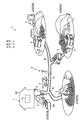
- FIG. 1 is a diagram schematically illustrating an example of a work vehicle management system according to the present embodiment.
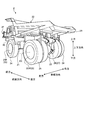
- FIG. 2 is a perspective view of the dump truck according to the present embodiment as viewed from the rear.
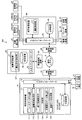
- FIG. 3 is a functional block diagram illustrating an example of a management device and a control device according to the present embodiment.
- FIG. 4 is a diagram schematically illustrating an example of an operation area in the loading field according to the present embodiment.
- FIG. 5 is a diagram schematically illustrating an example of an operation area in the loading field according to the present embodiment.
- FIG. 6 is a flowchart illustrating an example of a dump truck control method according to the present embodiment.
- FIG. 7 is a diagram schematically illustrating another example of the operation area in the loading area.
- FIG. 1 is a diagram schematically illustrating an example of a management system 1 for a work vehicle 2 according to the present embodiment.
- the management system 1 performs operation management of the work vehicle 2.
- the work vehicle 2 is a dump truck 2 that is a transport vehicle capable of traveling in a mine.
- the dump truck 2 travels at least a part of the mine work area PA and the conveyance path HL leading to the work place PA.
- the work place PA includes at least one of a loading place LPA and a dumping place DPA.
- the conveyance path HL includes an intersection IS.
- the dump truck 2 travels according to a travel route TR (see FIG. 4 and the like) set in the transport path HL and the work place PA.
- the loading area LPA is an area where loading work for loading a load onto the dump truck 2 is performed.
- a loading machine 3 such as a hydraulic excavator is operated.
- the loader 3 includes a control device 60 (see FIG. 3) described later.
- the earth removal site DPA is an area where a discharging operation for discharging the load from the dump truck 2 is performed.
- a crusher CR is provided in the earth removal site DPA.
- the management system 1 includes a management device 10 and a communication system 9.
- the management apparatus 10 includes a computer system and is installed in a control facility 7 provided in the mine.
- the communication system 9 performs data communication and signal communication between the management device 10 and the dump truck 2.
- the communication system 9 includes a plurality of repeaters 6 that relay data and signals.
- the management device 10 and the dump truck 2 communicate wirelessly via the communication system 9.
- the dump truck 2 is an unmanned dump truck that travels unattended without being operated by the driver.
- the dump truck 2 travels in the mine based on a command signal from the management device 10.
- the position of the dump truck 2 is detected using GNSS (Global Navigation Satellite System).
- the global navigation satellite system includes GPS (Global Positioning System).
- the GNSS has a plurality of positioning satellites 5.
- the GNSS detects a position defined by latitude, longitude, and altitude coordinate data.
- the position detected by GNSS is an absolute position defined in the global coordinate system.
- the absolute position of the dump truck 2 in the mine is detected by GNSS.
- FIG. 2 is a perspective view of the dump truck 2 according to the present embodiment as viewed from the rear.
- the dump truck 2 includes a vehicle body frame 21, a dump body 22 supported by the vehicle body frame 21, a travel device 23 that travels while supporting the vehicle body frame 21, and a control device 40.
- the traveling device 23 has wheels 25 on which tires 24 are mounted.
- the wheel 25 includes a front wheel 25F and a rear wheel 25R.
- the front wheels 25F are steered by a steering device 33 (see FIG. 3).
- the rear wheel 25R is not steered.
- the wheel 25 rotates about the rotation axis AX.
- a direction parallel to the rotation axis AX of the rear wheel 25R is appropriately referred to as a vehicle width direction
- a traveling direction of the dump truck 2 is appropriately referred to as a front-rear direction
- each of the vehicle width direction and the front-rear direction is appropriately referred to as the vertical direction.
- the front wheel 25F is disposed in front of the rear wheel 25R.
- the front wheels 25F are arranged on both sides in the vehicle width direction.
- the rear wheels 25R are disposed on both sides in the vehicle width direction.
- the dump body 22 is disposed above the vehicle body frame 21.
- the vehicle body frame 21 supports a driving device 31 (see FIG. 3) that generates a driving force for driving the traveling device 23.
- the dump body 22 is a member on which a load is loaded.
- the traveling device 23 has a rear axle 26 that transmits the driving force generated by the driving device 31 to the rear wheel 25R.
- the rear axle 26 includes an axle 27 that supports the rear wheel 25R.
- the rear axle 26 transmits the driving force generated by the driving device 31 to the rear wheel 25R.
- the rear wheel 25R rotates around the rotation axis AX by the driving force supplied from the rear axle 26. Thereby, the traveling device 23 travels.
- the dump truck 2 can move forward and backward.
- Advancing means driving
- Reverse travel means traveling with the rear portion 2R of the dump truck 2 facing the traveling direction.
- the control device 40 controls the dump truck 2.
- the control device 40 can control the dump truck 2 based on a command signal transmitted from the management device 10.
- the control system 100 includes a management device 10, a control device 40 for the dump truck 2, and a control device 60 for the loader 3.
- FIG. 3 is a functional block diagram illustrating an example of the management device 10, the control device 40, and the control device 60 according to the present embodiment.
- the management device 10 is installed in the control facility 7.
- the control device 40 is mounted on the dump truck 2.
- the management device 10 and the control device 40 communicate wirelessly via the communication system 9.
- the management device 10 includes a computer system.
- the management device 10 includes an arithmetic processing device 11 including a processor such as a CPU (Central Processing Unit), a storage device 12 including a memory and storage such as a ROM (Read Only Memory) or a RAM (Random Access Memory), and an input device. And an output interface 13.
- arithmetic processing device 11 including a processor such as a CPU (Central Processing Unit), a storage device 12 including a memory and storage such as a ROM (Read Only Memory) or a RAM (Random Access Memory), and an input device.
- ROM Read Only Memory
- RAM Random Access Memory
- the management device 10 is connected to the wireless communication device 14.
- the wireless communication device 14 is disposed in the control facility 7.
- the management device 10 communicates with the dump truck 2 via the wireless communication device 14 and the communication system 9.
- the management device 10 is connected to the input device 15 and the output device 16.
- the input device 15 and the output device 16 are installed in the control facility 7.
- the input device 15 includes, for example, at least one of a keyboard for a computer, a mouse, and a touch panel.
- Input data generated by operating the input device 15 is output to the management device 10.
- the output device 16 includes a display device.
- the display device includes a flat panel display such as a liquid crystal display (LCD) or an organic EL display (OELD).
- the output device 16 operates based on display data output from the management device 10.
- the output device 16 may be a printing device, for example.
- the arithmetic processing unit 11 includes a course data generation unit 111, an operation area setting unit 112, a traffic area setting unit 113, a determination unit 114, an outer partial data calculation unit 115, and an update data generation unit 116.
- the course data generation unit 111 generates course data CD indicating the traveling conditions of the dump truck 2 traveling in the mine.
- the traveling condition of the dump truck 2 includes at least one of a traveling route TR (see FIG. 4), a traveling speed, an acceleration, a deceleration, and a traveling direction of the dump truck 2. Further, the traveling condition of the dump truck 2 includes at least one of a stop position and a departure position of the dump truck 2.
- the course data generation unit 111 stores the generated course data CD in the storage device 12.
- the operation area setting unit 112 sets the operation area 50 (see FIG. 4).
- the operation area 50 is an area where the dump truck 2 can operate in the work area PA and the conveyance path HL.
- the operation area 50 is set based on position data acquired by, for example, a measurement vehicle equipped with GPS traveling in the work area PA.
- the outside of the operation area 50 is an area in which the dump truck 2 cannot be operated, and includes, for example, a wall portion W (see FIG. 4) and a bank.
- the operating area setting unit 112 generates operating area data 50 ⁇ / b> D indicating the range of the operating area 50 and stores it in the storage device 12.
- the traffic area setting unit 113 sets the traffic area 80 of the dump truck 2, and calculates traffic area data 80D indicating the range of the traffic area 80.
- the traffic area setting unit 113 can set an area having a predetermined width as the traffic area 80 along the travel route TR generated by the course data generation unit 111.
- the traffic region setting unit 113 extends in the traveling direction along the traveling route TR with the traveling route TR as a center, for example, and the width direction (direction orthogonal to the traveling direction) has a predetermined width than the vehicle width of the dump truck 2.
- a wide band-like region can be set as the passing region 80.
- the traffic area setting unit 113 can variably set the dimension in the width direction of the traffic area 80.
- the traffic area setting unit 113 stores the calculated traffic area data 80 ⁇ / b> D in the storage device 12.
- the determining unit 114 Based on the operating area data 50 ⁇ / b> D set by the operating area setting unit 112 and the traffic area data 80 ⁇ / b> D calculated by the traffic area setting unit 113, the determining unit 114 has the traffic area 80 outside the operating area 50. It is determined whether or not.
- the outer part data calculation unit 115 When the traffic area 80 exists outside the operation area 50, the outer part data calculation unit 115 indicates the outer part data indicating the range of the outer part 81 (see FIG. 5) existing outside the operation area 50 in the traffic area 80. 81D is calculated. The outer portion data calculation unit 115 stores the calculated outer portion data 81D in the storage device 12.
- the update data generation unit 116 generates update data 90D in which the operation area 50 is extended so as to extend outward of the traffic area 80.
- the update data 90D is data for updating the operation area data 50D.
- the update data generation unit 116 stores the generated update data 90D in the storage device 12.
- the input / output interface 13 receives the operation area data 50D set by the operation area setting unit 112, the course data CD generated by the course data generation unit 111, and the traffic area data 80D set by the traffic area setting unit 113, respectively. Output to the dump truck 2.
- the operation area data 50D, the course data CD, and the traffic area data 80D generated by the arithmetic processing device 11 are output to the dump truck 2 via the input / output interface 13 and the communication system 9.
- the control device 40 includes a computer system.
- the control device 40 includes an arithmetic processing device 41 including a processor such as a CPU (Central Processing Unit), a storage device 42 including a memory and storage such as a ROM (Read Only Memory) or a RAM (Random Access Memory), and an input device. And an output interface 43.
- arithmetic processing device 41 including a processor such as a CPU (Central Processing Unit), a storage device 42 including a memory and storage such as a ROM (Read Only Memory) or a RAM (Random Access Memory), and an input device.
- ROM Read Only Memory
- RAM Random Access Memory
- the control device 40 is connected to the wireless communication device 44.
- the wireless communication device 44 is disposed on the dump truck 2.
- the control device 40 communicates with the management device 10 via the wireless communication device 44 and the communication system 9.
- the control device 40 is connected to the drive device 31, the brake device 32, and the steering device 33.
- the control device 40 is connected to the position detector 34 and the detection device 35.
- the drive device 31, the brake device 32, the steering device 33, the position detector 34, and the detection device 35 are mounted on the dump truck 2.
- the driving device 31 operates to drive the traveling device 23 of the dump truck 2.
- the driving device 31 generates a driving force for driving the traveling device 23.
- the driving device 31 generates a driving force for rotating the rear wheel 25R.
- the drive device 31 includes an internal combustion engine such as a diesel engine.
- the drive device 31 may include a generator that generates electric power by the operation of the internal combustion engine and an electric motor that operates based on the electric power generated by the generator.
- the brake device 32 operates to brake the traveling device 23. By the operation of the brake device 32, the travel of the travel device 23 is decelerated or stopped.
- the steering device 33 operates to steer the traveling device 23 of the dump truck 2.
- the dump truck 2 is steered by the steering device 33.
- the steering device 33 steers the front wheel 25F.
- the position detector 34 detects the absolute position of the dump truck 2.
- the position detector 34 includes a GPS antenna that receives a GPS signal from the positioning satellite 5 and a GPS calculator that calculates the absolute position of the dump truck 2 based on the GPS signal received by the GPS antenna.
- the detection device 35 detects the traveling direction of the dump truck 2.
- the detection device 35 includes a steering angle sensor 35A that detects the steering angle of the dump truck 2 by the steering device 33, and an azimuth angle sensor 35B that detects the azimuth angle of the dump truck 2.
- the steering angle sensor 35A includes, for example, a rotary encoder provided in the steering device 33.
- the azimuth sensor 35B includes, for example, a gyro sensor provided on the vehicle body frame 21.
- the control device 40 is connected to the obstacle sensor 36.
- the obstacle sensor 36 is disposed, for example, at the lower part of the front portion of the vehicle body frame 21.
- the obstacle sensor 36 detects an obstacle in front of the dump truck 2 in a non-contact manner.
- the obstacle sensor 36 includes a plurality of radars and a laser sensor that is a non-contact sensor.
- the radar emits a radio wave, irradiates the radio wave on an obstacle, and receives the radio wave reflected by the obstacle. Thereby, the radar can detect the direction and distance of the obstacle with respect to the radar.
- the laser sensor detects the position of an object around the dump truck 2, emits a laser beam, irradiates the obstacle that is the object, and receives the laser beam reflected by the obstacle. Thereby, the laser sensor can detect the direction and distance of the obstacle with respect to the laser sensor. Since the laser sensor emits a laser beam and receives the reflected laser beam, the resolution is higher than that of the radar.
- the arithmetic processing unit 41 has an operation control unit 411.
- the driving control unit 411 outputs a driving control signal for controlling at least one of the driving device 31, the brake device 32, and the steering device 33 of the dump truck 2 based on the course data CD generated by the course data generating unit 111.
- the driving control signal includes an accelerator signal output to the drive device 31, a brake command signal output to the brake device 32, and a steering command signal output to the steering device 33.
- the arithmetic processing device 41 transmits the position data of the dump truck 2 detected by the position detector 34 to the management device 10 by the wireless communication device 44.
- the control device 60 includes a computer system.
- the control device 60 includes an arithmetic processing device 61 including a processor such as a CPU (Central Processing Unit), a storage device 62 including a memory and storage such as a ROM (Read Only Memory) or a RAM (Random Access Memory), and an input device. And an output interface 63.
- arithmetic processing device 61 including a processor such as a CPU (Central Processing Unit), a storage device 62 including a memory and storage such as a ROM (Read Only Memory) or a RAM (Random Access Memory), and an input device.
- ROM Read Only Memory
- RAM Random Access Memory
- the control device 60 is connected to the wireless communication device 64.
- the wireless communication device 64 is disposed in the loader 3.
- the control device 60 communicates with the management device 10 via the wireless communication device 64 and the communication system 9.
- the arithmetic processing unit 61 has a loading instruction control unit 611.
- the loading instruction control unit 611 is configured such that the dump truck 2 approaches the position of the loading point LPP (see FIG. 4) of the loading by the loading machine 3, the type of the course passing through the loading point LPP, and the loading point LPP. The direction and the direction of the dump truck 2 at the loading point LPP are set.
- the loading instruction control unit 611 transmits the set setting items to the management device 10 by the wireless communication device 44.
- a type of the course which passes the loading point LPP a drive-by type and a switchback type are mentioned, for example. As shown in FIG.
- the drive-by type course is a course in which the dump truck 2 reaches the loading point LPP by advancing and loads and then starts moving forward.
- the switchback type course is a course in which the dump truck 2 moving forward changes its traveling direction at an acute angle, reaches the LPP in the reverse direction, loads the load, and then starts moving forward as shown in FIG.
- FIGS. 4 and 5 are diagrams schematically showing an example of the operation area 50 in the loading site LPA according to the present embodiment.
- the operating area setting unit 112 sets the operating area 50.
- the operating area 50 has a boundary line 51.
- the boundary line 51 is set along the wall portion W, for example.
- the travel route TR includes an aggregate of a plurality of course points set at regular intervals.
- Each of the plurality of course points includes the absolute position data of the dump truck 2, the traveling speed data of the dump truck 2 at the position where the course point is set, and the traveling direction data of the dump truck 2 at the position where the course point is set. including.
- the travel route TR of the dump truck 2 is defined by a trajectory passing through a plurality of course points.
- the travel route TR is set linearly. Based on the traveling speed data, the traveling speed of the dump truck 2 at the position where the course point is set is defined. Based on the traveling direction data, the traveling direction of the dump truck 2 at the position where the course point is set is defined.
- the travel route TR defined by the course point is a target travel route.
- the traveling speed of the dump truck 2 defined by the course point is a target traveling speed.
- the traveling direction of the dump truck 2 defined by the course point is the target traveling direction. Even if the loading point LPP is set outside the operation area 50, the course data generation unit 111 generates the travel route TR within the predetermined distance from the boundary line 51.
- the dump truck 2 travels the loading site LPA according to the travel route TR after acquiring the generated travel route TR.
- the traffic area setting unit 114 sets the traffic area 80 in front of the traveling direction of the dump truck 2. Accordingly, the dump truck 2 travels in a state in which the traffic area 80 is set in front of the traveling direction.
- the course defined by the travel route TR is, for example, a course in which the dump truck 2 arrives forward with respect to the loading point LPP, loads the load, and starts forward (drive-by). is there.
- the dump truck 2 arrives forward from the position P1 in the loading site LPA to the position P2 where the loading point LPP is set, loads the load, and then starts moving forward. Passes through a predetermined position P3.
- the position P1, the position P2, and the position P3 are positions on the course defined by the travel route TR. Further, the position P3 can be set at a point away from the loading point LPP by a predetermined distance.
- a part of the wall W is mined by a loading machine 3 such as a hydraulic excavator.
- a loading machine 3 such as a hydraulic excavator.
- the operation area setting unit 112 needs to update the operation area 50 so as to correspond to the change in the shape of the wall W.
- the travel region setting unit 113 calculates the travel region data 80D indicating the range of the travel region 80 having a predetermined width along the travel route TR. To do.
- the determination unit 114 determines whether the traffic area 80 exists outside the operation area 50 based on the operation area data 50D and the traffic area data 80D. For example, as shown in FIG. 5, when there is an overlapping portion 51 a that overlaps the traffic area 80 in the boundary line 51 of the operation area 50, the determination unit 114 exists outside the operation area 50. It is determined that In addition, the determination unit 114 determines that the traffic area 80 does not exist outside the operation area 50 when there is no overlapping portion 51 a that overlaps the traffic area 80 in the boundary line 51 of the operation area 50.
- the traffic area 80 exists outside the operation area 50, that is, the traffic area 80 has an outer portion 81 outside the operation area 50 will be described as an example.
- the outer part data calculation unit 115 calculates outer part data 81 ⁇ / b> D indicating the range of the outer part 81.
- the outer portion 81 is a boundary update scheduled area scheduled to update the boundary line 51 of the operating area 50.
- the update data generation unit 116 updates the operation area 50 according to the range of the outer part 81 of the passage area 80 (see FIG. 3). Is generated.
- the update data 90D is data for updating the operation area data 50D.
- the operating area 50 defined by the update data 90D has a shape in which the boundary line 51 has a protruding portion 51b.
- the protruding portion 51 b is disposed outside the passing area 80 and is disposed along the outline 82 of the outer portion 81.
- the updated boundary line 51 including the protruding portion 51 b is arranged along the outline of the passage area 80.
- the protruding portion 51b may be disposed at a position overlapping the outline of the outer portion 81. Further, the update data generation unit 116 may set at least a part of the protruding portion 51 b within the range of the offset portion of the outer portion 81.
- FIG. 6 is a flowchart showing an example of a method for controlling the dump truck 2 according to the present embodiment.
- the operation control unit 411 causes the dump truck 2 to travel along the travel route TR.
- the dump truck 2 moves forward from the position P1 and moves to the loading point LPP.
- the dump truck 2 starts moving forward, passes through the position P3, and moves to the outside from the loading field LPA.
- the operation control unit 411 transmits the position detected by the position detection unit 34 to the management device 10 via the communication system 9.
- the above loading operation may be performed by a plurality of dump trucks 2.
- the second and subsequent dump trucks 2 sequentially move to the loading point LPP for loading.
- the traffic area setting unit 113 calculates a traffic area 80 having a predetermined width along the travel route TR generated by the course data generation unit 111 (step S20).
- step S30 the arithmetic processing unit 11 calculates a boundary update scheduled area (step S30).
- the determination unit 114 determines whether or not the traffic area 80 exists outside the operation area 50, based on the operation area data 50D and the traffic area data 80D.
- the outer part data calculation unit 115 calculates outer part data 81D indicating the range of the outer part 81 (boundary update scheduled area). On the other hand, if it is determined that the traffic area 80 does not exist outside the operation area 50, the process is terminated.
- the determination unit 114 determines whether or not the dump truck 2 has passed the predetermined position P3 (step S40). In step S ⁇ b> 40, the determination unit 114 performs determination based on the position transmitted from the dump truck 2. When it is determined that the dump truck 2 does not pass the predetermined position P3 (No in step S40), the determination in step S40 is repeated until the dump truck 2 passes the predetermined position P3.
- Step S50 the determination unit 114 determines whether or not the operating area data 50D has already been updated. In step S50, the determination unit 114 determines that the operation area data 50D is not updated when the dump truck 2 first passes through the course passing through the loading point LPP (No in step S50). Further, the determination unit 114 determines that the operation area data 50D has been updated when the dump truck 2 passes through the course passing through the loading point LPP after the second unit (Yes in step S50).
- the update data generation unit 116 expands the operation area 50 according to the range of the outer portion 81 of the traffic area 80.
- Update data 90D is generated (step S60).
- the operating area setting unit 112 reflects the generated update data 90D in the operating area data 50D (step S70). As a result, the operating area 50 is deformed into a shape corresponding to the outer portion 81.
- step S50 If the determination unit 114 determines that the operating area data 50D has been updated (Yes in step S50), the process ends without performing steps S60 and S70.
- the work vehicle control system 100 includes the course data generation unit 111 that generates the travel condition including the travel route TR of the dump truck 2 in the work area PA, and the area in which the dump truck 2 can operate.
- An operation area setting unit 112 that sets an operation area 50
- a traffic area setting unit 113 that sets a traffic area 80 having a predetermined width along the travel route TR generated by the course data generation unit 111, and a traffic area 80.
- an update data generation unit 116 that generates update data 90D of the operation area data 50D obtained by expanding the operation area 50 is provided.
- the operation area 50 when the traffic area 80 exists outside the operation area 50, the operation area 50 is expanded in accordance with the range of the outer portion 81. Can be extended. Thereby, since the dump truck 2 can be operated according to the change of the area
- the update data generation unit 116 generates update data 90D in which the operation area 50 is extended so as to extend in the outward direction of the traffic area 80.
- the operation area 50 can be expanded to an area wider than the area through which the dump truck 2 has actually passed.
- the update data generation unit 116 generates update data 90D in which the operation area 50 is extended so that the boundary line 51 of the operation area 50 is along the outline 82 of the outer portion 81. Therefore, it is possible to prevent the operation area 50 from being excessively expanded.
- the update data generation unit 116 generates update data 90D that is deformed so that the boundary line 51 of the operating region 50 overlaps the outline 82 of the outer portion 81. Thereby, it can suppress more reliably that the operation area
- the dump truck 2 has been described as an example of a so-called drive-by type course in which the dump truck 2 arrives forward with respect to the loading point LPP. is not.
- the course may be a switchback type course in which the dump truck 2 switches back and reaches the loading point LPP.
- FIG. 7 is a diagram schematically showing another example of the operation area 50 in the loading area LPA.
- the operating area setting unit 112 sets the operating area 55.
- the boundary line 56 of the operation area 55 is set along the wall portion W, for example.
- the course data generating unit 111 travels along the loading point LPP. Generate TR.
- the course defined by the travel route TR is, for example, a course in which the dump truck 2 arrives in reverse by switching back to the loading point LPP. In this case, the dump truck 2 moves backward to reach the loading point LPP, and after loading by the loader 3 at the loading point LPP, the dump truck 2 travels forward from the loading point LPP.
- the traffic area setting unit 113 calculates traffic area data indicating the range of the traffic area 85 of the dump truck 2.
- the rear end of the dump body 22 is disposed so as to protrude rearward from the rear wheel 25R, and a space is provided between the dump body 22 and the ground. For this reason, the rear end of the dump body 22 can pass even above the protrusion that protrudes to a predetermined height from the ground. On the other hand, it may be difficult for the rear wheel 25R to pass above such a protrusion. Thus, even if the rear end of the dump body 22 can pass, the rear wheel 25R is not necessarily allowed to pass. Therefore, the traffic area setting unit 114 does not set the traffic area 80 behind the rotational axis AX of the rear wheel 25R of the dump truck 2.
- the determination unit 114 determines whether or not the traffic area 85 exists outside the operation area 55 based on the operation area data and the traffic area data.
- the case where the traffic area 85 has the outer portion 86 outside the operation area 55 will be described as an example.
- the outer part data calculation unit 115 calculates outer part data indicating the range of the outer part 86.
- the update data generation unit 116 When the outer part data is calculated, the update data generation unit 116 generates update data in which the operation area 55 is expanded according to the range of the outer part 86 of the traffic area 85.
- the update data is data for updating the operation area data.
- the operating area 55 defined by the update data has a shape in which the boundary line 56 has a protruding portion 56b.
- the protruding portion 56 b is disposed outside the passage area 85 and is disposed along the outline 87 of the outer portion 86.
- the updated boundary line 56 is arranged along the outline of the passage area 85 including the protruding portion 56b.
- the protruding portion 56b may be disposed at a position overlapping the outer periphery of the outer portion 86.
- the management system 1 of the work vehicle 2 extends the operation area 55 to include at least a part of the outer portion 86 of the passage area 85 even when reaching the loading point LPP by switchback,
- the operation area 55 can be expanded to an area where the dump truck 2 can travel. Thereby, since the dump truck 2 can be operated according to the change of the area
- the dump truck 2 is an unmanned dump truck.
- the dump truck 2 may be a manned dump truck that travels according to an operation of a driver who has boarded the dump truck 2.
- the work vehicle used in the mine has been described as an example.
- the component demonstrated by the above-mentioned embodiment may be applied to the work vehicle used in the work site different from a mine.
- the work vehicle may not be the dump truck 2, and may be a work vehicle capable of performing a loading operation such as a wheel loader.
- the course data generation unit 111 the operation area data acquisition unit 112, the traffic area setting unit 113, the determination unit 114, the outer partial data calculation unit 115, and the update data generation unit 116 are provided in the management apparatus 10.
- the present invention is not limited to this, and at least one of the above may be provided in the control device 40 of the dump truck 2.
- the travel route TR has been described as an example in which data is handled as an aggregate of a plurality of course points.
- the present invention is not limited to this.
- the data may be handled as a curve.
- CD Course data
- W Wall part
- PA Work place
- HL Conveyance path
- CR Crusher
- AX ... Rotating shaft, IS ... Intersection, LPA ... Loading place, LPP ... Loading point, TR ... Traveling route, DESCRIPTION OF SYMBOLS 1 ... Management system, 2 ... Dump truck, 2F ... Front part, 2R ... Rear part, 3 ... Loading machine, 5 ... Positioning satellite, 6 ... Repeater, 7 ... Control facility, 9 ... Communication system, 10 ... Management device, DESCRIPTION OF SYMBOLS 11, 41, 61 ... Arithmetic processing unit, 12, 42, 62 ... Storage device, 13, 43, 63 ...
Landscapes
- Engineering & Computer Science (AREA)
- Radar, Positioning & Navigation (AREA)
- Remote Sensing (AREA)
- Physics & Mathematics (AREA)
- General Physics & Mathematics (AREA)
- Aviation & Aerospace Engineering (AREA)
- Automation & Control Theory (AREA)
- Civil Engineering (AREA)
- General Engineering & Computer Science (AREA)
- Structural Engineering (AREA)
- Mining & Mineral Resources (AREA)
- Control Of Position, Course, Altitude, Or Attitude Of Moving Bodies (AREA)
- Traffic Control Systems (AREA)
Abstract
Description
本実施形態に係る作業車両2の管理システム1について説明する。図1は、本実施形態に係る作業車両2の管理システム1の一例を模式的に示す図である。管理システム1は、作業車両2の運行管理を実施する。本実施形態において、作業車両2は、鉱山を走行可能な運搬車両であるダンプトラック2である。
次に、本実施形態に係るダンプトラック2について説明する。図2は、本実施形態に係るダンプトラック2を後方から見た斜視図である。図2に示すように、ダンプトラック2は、車体フレーム21と、車体フレーム21に支持されるダンプボディ22と、車体フレーム21を支持して走行する走行装置23と、制御装置40とを備える。
次に、本実施形態に係る作業車両の制御システム100について説明する。制御システム100は、管理装置10と、ダンプトラック2の制御装置40と、積込機3の制御装置60とを有する。図3は、本実施形態に係る管理装置10、制御装置40及び制御装置60の一例を示す機能ブロック図である。管理装置10は、管制施設7に設置される。制御装置40は、ダンプトラック2に搭載される。管理装置10と制御装置40とは、通信システム9を介して無線通信する。
次に、本実施形態に係るダンプトラック2の制御方法の一例について説明する。図6は、本実施形態に係るダンプトラック2の制御方法の一例を示すフローチャートである。積込機3の積込指示制御部611で積込点LPPの位置が指定され、通信システム9を介して管理装置10に送信された場合、管理装置10のコースデータ生成部111は、積込点LPPの位置に基づいて、ダンプトラック2の走行条件を示す走行経路TRを生成する(ステップS10)。コースデータ生成部111は、通信システム9を介して、生成した走行経路TRをダンプトラック2に送信する。
Claims (7)
- 作業場における作業車両の走行経路を含む走行条件を生成するコースデータ生成部と、
前記作業車両の稼働可能な領域である稼働領域を設定する稼動領域設定部と、
前記コースデータ生成部が生成した前記走行経路に沿って所定幅を有する通行領域を設定する通行領域設定部と、
前記通行領域が前記稼動領域の外側に存在する場合、前記稼動領域を拡張した前記稼動領域データの更新データを生成する更新データ生成部と
を備える作業車両の制御システム。 - 前記更新データ生成部は、前記通行領域の外側方向に拡がるように前記稼動領域を拡張した前記更新データを生成する
請求項1に記載の作業車両の制御システム。 - 前記更新データ生成部は、前記稼動領域の境界線が前記外側部分の外郭線に沿うように前記稼動領域を拡張した前記更新データを生成する
請求項1又は請求項2に記載の作業車両の制御システム。 - 前記更新データ生成部は、前記稼動領域の境界線が前記外側部分の外郭線に重なるように前記稼動領域を拡張した前記更新データを生成する
請求項1から請求項3のいずれか一項に記載の作業車両の制御システム。 - 前記更新データ生成部は、前記作業車両が前記走行経路の所定の地点を通過した場合に前記更新データを生成する
請求項1から請求項4のいずれか一項に記載の作業車両の制御システム。 - 請求項1から請求項5のいずれか一項に記載の作業車両の制御システムを備える作業車両。
- 作業場における作業車両の走行経路を含む走行条件を生成することと、
前記作業車両の稼働可能な領域である稼働領域を設定することと、
生成された前記走行経路に沿って所定幅を有する通行領域を設定することと、
前記通行領域が前記稼動領域の外側に存在する場合、前記稼動領域を拡張した前記稼動領域データの更新データを生成することと
を含む作業車両の制御方法。
Priority Applications (6)
| Application Number | Priority Date | Filing Date | Title |
|---|---|---|---|
| CA2992244A CA2992244C (en) | 2017-03-31 | 2017-03-31 | Control system for work vehicle, work vehicle, and control method for work vehicle |
| AU2017241973A AU2017241973B2 (en) | 2017-03-31 | 2017-03-31 | Control system for work vehicle, work vehicle, and control method for work vehicle |
| CN201780002060.9A CN107710097A (zh) | 2017-03-31 | 2017-03-31 | 作业车辆的控制系统、作业车辆及作业车辆的控制方法 |
| JP2017539387A JP6297228B2 (ja) | 2017-03-31 | 2017-03-31 | 作業車両の制御システム、作業車両、及び作業車両の制御方法 |
| PCT/JP2017/013859 WO2017171089A1 (ja) | 2017-03-31 | 2017-03-31 | 作業車両の制御システム、作業車両、及び作業車両の制御方法 |
| US15/735,735 US10635112B2 (en) | 2017-03-31 | 2017-03-31 | Control system for work vehicle, work vehicle, and control method for work vehicle |
Applications Claiming Priority (1)
| Application Number | Priority Date | Filing Date | Title |
|---|---|---|---|
| PCT/JP2017/013859 WO2017171089A1 (ja) | 2017-03-31 | 2017-03-31 | 作業車両の制御システム、作業車両、及び作業車両の制御方法 |
Publications (1)
| Publication Number | Publication Date |
|---|---|
| WO2017171089A1 true WO2017171089A1 (ja) | 2017-10-05 |
Family
ID=59965995
Family Applications (1)
| Application Number | Title | Priority Date | Filing Date |
|---|---|---|---|
| PCT/JP2017/013859 Ceased WO2017171089A1 (ja) | 2017-03-31 | 2017-03-31 | 作業車両の制御システム、作業車両、及び作業車両の制御方法 |
Country Status (6)
| Country | Link |
|---|---|
| US (1) | US10635112B2 (ja) |
| JP (1) | JP6297228B2 (ja) |
| CN (1) | CN107710097A (ja) |
| AU (1) | AU2017241973B2 (ja) |
| CA (1) | CA2992244C (ja) |
| WO (1) | WO2017171089A1 (ja) |
Families Citing this family (7)
| Publication number | Priority date | Publication date | Assignee | Title |
|---|---|---|---|---|
| WO2017163790A1 (ja) * | 2017-02-28 | 2017-09-28 | 株式会社小松製作所 | 作業車両の制御装置、作業車両、及び作業車両の制御方法 |
| JP7303027B2 (ja) * | 2019-06-03 | 2023-07-04 | 株式会社小松製作所 | 作業機械を制御するためのシステムおよび方法 |
| JP7352911B2 (ja) * | 2020-03-10 | 2023-09-29 | 株式会社小松製作所 | 運搬車両を制御するためのシステム及び方法 |
| JP7137605B2 (ja) * | 2020-11-06 | 2022-09-14 | 日立建機株式会社 | 車両管理システム |
| JP7637539B2 (ja) * | 2021-03-16 | 2025-02-28 | 株式会社小松製作所 | 無人車両の管理システム及び無人車両の管理方法 |
| CN114895707B (zh) * | 2022-05-13 | 2023-06-30 | 华南农业大学 | 基于变频蝙蝠算法的农业无人机路径规划方法及系统 |
| US20250188708A1 (en) * | 2023-12-12 | 2025-06-12 | Caterpillar Inc. | System and method for delivering beams to predetermined locations of worksite |
Citations (4)
| Publication number | Priority date | Publication date | Assignee | Title |
|---|---|---|---|---|
| JP2005069714A (ja) * | 2003-08-27 | 2005-03-17 | Fujitsu Ten Ltd | ナビゲーション装置およびこれを用いた地図情報配信システム |
| WO2014097445A1 (ja) * | 2012-12-20 | 2014-06-26 | パイオニア株式会社 | 地図情報生成装置及び地図情報生成方法 |
| JP2016090864A (ja) * | 2014-11-06 | 2016-05-23 | 日立建機株式会社 | 地図生成装置 |
| JP2017049172A (ja) * | 2015-09-03 | 2017-03-09 | 日立建機株式会社 | 作業機械の地図作成装置及び方法 |
Family Cites Families (2)
| Publication number | Priority date | Publication date | Assignee | Title |
|---|---|---|---|---|
| JP5140864B2 (ja) | 2010-11-22 | 2013-02-13 | 株式会社小松製作所 | 無人車両の走行システムおよび走行経路生成方法 |
| US20150310674A1 (en) * | 2014-04-29 | 2015-10-29 | Caterpillar Inc. | System for providing on-site service for industrial equipment |
-
2017
- 2017-03-31 US US15/735,735 patent/US10635112B2/en active Active
- 2017-03-31 WO PCT/JP2017/013859 patent/WO2017171089A1/ja not_active Ceased
- 2017-03-31 CA CA2992244A patent/CA2992244C/en active Active
- 2017-03-31 AU AU2017241973A patent/AU2017241973B2/en active Active
- 2017-03-31 CN CN201780002060.9A patent/CN107710097A/zh active Pending
- 2017-03-31 JP JP2017539387A patent/JP6297228B2/ja active Active
Patent Citations (4)
| Publication number | Priority date | Publication date | Assignee | Title |
|---|---|---|---|---|
| JP2005069714A (ja) * | 2003-08-27 | 2005-03-17 | Fujitsu Ten Ltd | ナビゲーション装置およびこれを用いた地図情報配信システム |
| WO2014097445A1 (ja) * | 2012-12-20 | 2014-06-26 | パイオニア株式会社 | 地図情報生成装置及び地図情報生成方法 |
| JP2016090864A (ja) * | 2014-11-06 | 2016-05-23 | 日立建機株式会社 | 地図生成装置 |
| JP2017049172A (ja) * | 2015-09-03 | 2017-03-09 | 日立建機株式会社 | 作業機械の地図作成装置及び方法 |
Also Published As
| Publication number | Publication date |
|---|---|
| JP6297228B2 (ja) | 2018-03-20 |
| CN107710097A (zh) | 2018-02-16 |
| US20180284784A1 (en) | 2018-10-04 |
| CA2992244A1 (en) | 2017-10-05 |
| AU2017241973B2 (en) | 2019-01-03 |
| AU2017241973A1 (en) | 2018-10-18 |
| CA2992244C (en) | 2020-06-30 |
| US10635112B2 (en) | 2020-04-28 |
| JPWO2017171089A1 (ja) | 2018-04-05 |
Similar Documents
| Publication | Publication Date | Title |
|---|---|---|
| JP6297228B2 (ja) | 作業車両の制御システム、作業車両、及び作業車両の制御方法 | |
| JP6529595B2 (ja) | 運搬車両の制御システム、運搬車両、及び運搬車両の制御方法 | |
| US11327505B2 (en) | Control apparatus of work vehicle, work vehicle, and control method of work vehicle | |
| JP5997364B2 (ja) | 鉱山機械、鉱山機械の管理システム、及び鉱山機械の管理方法 | |
| US11650589B2 (en) | Management system for work vehicle and management method for work vehicle | |
| US11835643B2 (en) | Work machine control system, work machine, and work machine control method | |
| CN109478067B (zh) | 作业车辆的管理系统及作业车辆的管理方法 | |
| JP6761845B2 (ja) | ダンプトラックの制御システム、及びダンプトラック | |
| JP2020074248A (ja) | 運搬車両の管理システム |
Legal Events
| Date | Code | Title | Description |
|---|---|---|---|
| ENP | Entry into the national phase |
Ref document number: 2017539387 Country of ref document: JP Kind code of ref document: A |
|
| WWE | Wipo information: entry into national phase |
Ref document number: 15735735 Country of ref document: US |
|
| ENP | Entry into the national phase |
Ref document number: 2992244 Country of ref document: CA |
|
| ENP | Entry into the national phase |
Ref document number: 2017241973 Country of ref document: AU Date of ref document: 20170331 Kind code of ref document: A |
|
| 121 | Ep: the epo has been informed by wipo that ep was designated in this application |
Ref document number: 17775620 Country of ref document: EP Kind code of ref document: A1 |
|
| NENP | Non-entry into the national phase |
Ref country code: DE |
|
| 122 | Ep: pct application non-entry in european phase |
Ref document number: 17775620 Country of ref document: EP Kind code of ref document: A1 |