WO2017171075A1 - 眼鏡レンズおよび眼鏡 - Google Patents
眼鏡レンズおよび眼鏡 Download PDFInfo
- Publication number
- WO2017171075A1 WO2017171075A1 PCT/JP2017/013803 JP2017013803W WO2017171075A1 WO 2017171075 A1 WO2017171075 A1 WO 2017171075A1 JP 2017013803 W JP2017013803 W JP 2017013803W WO 2017171075 A1 WO2017171075 A1 WO 2017171075A1
- Authority
- WO
- WIPO (PCT)
- Prior art keywords
- spectacle lens
- lens
- blue light
- eyeball
- object side
- Prior art date
Links
Images


Classifications
-
- G—PHYSICS
- G02—OPTICS
- G02C—SPECTACLES; SUNGLASSES OR GOGGLES INSOFAR AS THEY HAVE THE SAME FEATURES AS SPECTACLES; CONTACT LENSES
- G02C7/00—Optical parts
- G02C7/10—Filters, e.g. for facilitating adaptation of the eyes to the dark; Sunglasses
-
- G—PHYSICS
- G02—OPTICS
- G02B—OPTICAL ELEMENTS, SYSTEMS OR APPARATUS
- G02B5/00—Optical elements other than lenses
- G02B5/20—Filters
- G02B5/22—Absorbing filters
- G02B5/223—Absorbing filters containing organic substances, e.g. dyes, inks or pigments
-
- G—PHYSICS
- G02—OPTICS
- G02B—OPTICAL ELEMENTS, SYSTEMS OR APPARATUS
- G02B5/00—Optical elements other than lenses
- G02B5/20—Filters
- G02B5/26—Reflecting filters
-
- G—PHYSICS
- G02—OPTICS
- G02B—OPTICAL ELEMENTS, SYSTEMS OR APPARATUS
- G02B5/00—Optical elements other than lenses
- G02B5/20—Filters
- G02B5/28—Interference filters
- G02B5/283—Interference filters designed for the ultraviolet
-
- G—PHYSICS
- G02—OPTICS
- G02B—OPTICAL ELEMENTS, SYSTEMS OR APPARATUS
- G02B5/00—Optical elements other than lenses
- G02B5/20—Filters
- G02B5/28—Interference filters
- G02B5/285—Interference filters comprising deposited thin solid films
-
- G—PHYSICS
- G02—OPTICS
- G02C—SPECTACLES; SUNGLASSES OR GOGGLES INSOFAR AS THEY HAVE THE SAME FEATURES AS SPECTACLES; CONTACT LENSES
- G02C7/00—Optical parts
- G02C7/10—Filters, e.g. for facilitating adaptation of the eyes to the dark; Sunglasses
- G02C7/104—Filters, e.g. for facilitating adaptation of the eyes to the dark; Sunglasses having spectral characteristics for purposes other than sun-protection
-
- G—PHYSICS
- G02—OPTICS
- G02C—SPECTACLES; SUNGLASSES OR GOGGLES INSOFAR AS THEY HAVE THE SAME FEATURES AS SPECTACLES; CONTACT LENSES
- G02C7/00—Optical parts
- G02C7/10—Filters, e.g. for facilitating adaptation of the eyes to the dark; Sunglasses
- G02C7/107—Interference colour filters
-
- G—PHYSICS
- G02—OPTICS
- G02C—SPECTACLES; SUNGLASSES OR GOGGLES INSOFAR AS THEY HAVE THE SAME FEATURES AS SPECTACLES; CONTACT LENSES
- G02C7/00—Optical parts
- G02C7/10—Filters, e.g. for facilitating adaptation of the eyes to the dark; Sunglasses
- G02C7/108—Colouring materials
Definitions
- the present invention relates to a spectacle lens and spectacles provided with the spectacle lens.
- JP 2013-8052 A proposes an optical article having a multilayer film having a property of reflecting light having a wavelength of 400 to 450 nm on a convex surface and a concave surface of a plastic substrate. .
- a multilayer lens having a property of reflecting blue light on both surfaces of a lens substrate is used.
- a film may be provided.
- the spectacle lens can be used by a spectacle wearer with a good wearing feeling and has a good appearance.
- the reflectance of blue light on both sides of the spectacle lens is increased, the amount of blue light incident on the wearer's eye through the spectacle lens can be reduced, but the wearing feeling and appearance of the spectacle lens tend to deteriorate.
- One embodiment of the present invention provides a spectacle lens that can reduce the burden on the eye caused by blue light and has a good wearing feeling and appearance.
- a spectacle lens comprising a lens substrate, a multilayer film located on the object side surface of the lens substrate, and a multilayer film located on the eyeball side surface of the lens substrate, Blue light absorption is 10.0% or more,
- the lens substrate includes a blue light absorbing compound,
- the average reflectance in the wavelength region of 400 to 500 nm measured on the object side surface and the eyeball side surface of the spectacle lens is in the range of 10.0 to 20.0%, and the object side surface and the eyeball side surface of the spectacle lens Eyeglass lenses each having a luminous reflectance measured less than 2.0%, About.
- the spectacle lens has a multilayer film on the object-side surface and the eyeball-side surface of the lens substrate. That is, it has a multilayer film on both surfaces of the spectacle lens.
- the average reflectance in the wavelength region of 400 to 500 nm (hereinafter also referred to as “blue light reflectance”) measured on the object side surface and the eyeball side surface of the spectacle lens is 10.0 to 20.0%. Range. Thereby, the spectacle lens can reflect blue light with high reflectivity on both surfaces thereof.
- the obtained spectacle lens tends to be inferior in wearing feeling and appearance. This is because a double image called a ghost is generated and glare is generated on both sides of the spectacle lens.
- the spectacle lens includes a blue light-absorbing compound in the lens base material, and the blue light absorption rate of the spectacle lens is 10.0% or more. Thereby, it becomes possible to suppress the occurrence of ghost. Details will be described later. Further, with regard to the feeling of wearing and the appearance, the occurrence of glare on the object-side surface of the spectacle lens causes a decrease in the appearance quality of the spectacle lens.
- the spectacle lens has high blue light reflectance on both sides of the spectacle lens, the luminous reflectance measured on both sides is less than 2.0%. Thereby, it is possible to suppress the occurrence of glare on the object side surface of the spectacle lens and the glare on the eyeball side surface, respectively.
- a further aspect of the present invention relates to spectacles having the spectacle lens and a frame to which the spectacle lens is attached.
- a spectacle lens that can reduce the burden on the eyes caused by blue light and that has a good wearing feeling and appearance, and spectacles including the spectacle lens.
- the reflection spectrum and transmission spectrum of the spectacle lens of Example 1 are shown.
- the reflection spectrum and transmission spectrum of the spectacle lens of Reference Example 1 are shown.
- the reflection spectrum and transmission spectrum of the spectacle lens of the comparative example 1 are shown.
- the reflection spectrum and transmission spectrum of the spectacle lens of Example 2 are shown.
- the reflection spectrum and transmission spectrum of the spectacle lens of the comparative example 2 are shown.
- the reflection spectrum and transmission spectrum of the spectacle lens of Example 3 are shown.
- the reflection spectrum and transmission spectrum of the spectacle lens of the comparative example 3 are shown.
- the reflection spectrum and transmission spectrum of the spectacle lens of the comparative example 4 are shown.
- the reflection spectrum and transmission spectrum of the spectacle lens of Example 4 are shown.
- the reflection spectrum and transmission spectrum of the spectacle lens of Example 5 are shown.
- the reflection spectrum and transmission spectrum of the spectacle lens of Example 6 are shown.
- the reflection spectrum and transmission spectrum of the spectacle lens of Example 7 are shown.
- the reflection spectrum and transmission spectrum of the spectacle lens of Example 8 are shown.
- An eyeglass lens according to one aspect of the present invention includes a lens base material, a multilayer film positioned on an eyeball side surface of the lens base material, and a multilayer film positioned on an object side surface of the lens base material.
- the blue light absorption is 10.0% or more
- the lens base material contains a blue light absorbing compound, and has a wavelength of 400 to 500 nm measured on the object side surface and the eyeball side surface of the spectacle lens, respectively.
- the average reflectance in the wavelength region is in the range of 10.0 to 20.0%, and the luminous reflectance measured on the object side surface and the eyeball side surface of the spectacle lens is less than 2.0%.
- the “object side surface” is a surface located on the object side when the spectacles equipped with spectacle lenses are worn by the wearer, and the “eye side surface” is the opposite, that is, spectacles equipped with spectacle lenses. Is a surface located on the eyeball side when worn by the wearer.
- Bluetooth light absorptance refers to spectacle lenses and is determined by the following method.
- the transmittance and reflectance in the wavelength range of 380 nm to 500 nm are measured with a spectrophotometer.
- measurement light for which reflection, transmission, or absorption is to be obtained shall mean normal incidence light. Therefore, the transmittance and reflectance described above are the transmittance and reflectance with respect to the direct incident light. Measurement is performed at the optical center.
- the measurement wavelength interval (pitch) can be arbitrarily set for measurement. For example, it can be arbitrarily set within the range of 1 to 5 nm.
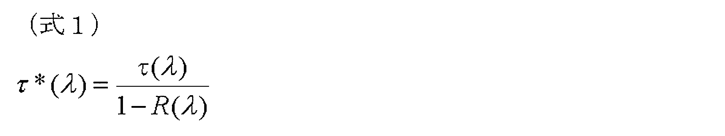
- the transmittance measured by the spectrophotometer does not take into account the component reflected on the surface of the spectacle lens in the incident light. Therefore, similarly to the light absorbed by the spectacle lens, the light that is reflected by the spectacle lens surface and is not incident on the lens is also observed as a decrease in the transmission amount in the spectrophotometer measurement. Therefore, the transmittance ⁇ * ( ⁇ ) at the wavelength ⁇ nm after subtracting the influence of reflection is calculated by the following equation 1.
- ⁇ ( ⁇ ) is the transmittance at the wavelength ⁇ nm measured by the spectrophotometer
- R ( ⁇ ) is the reflectance at the wavelength ⁇ nm measured by the spectrophotometer.
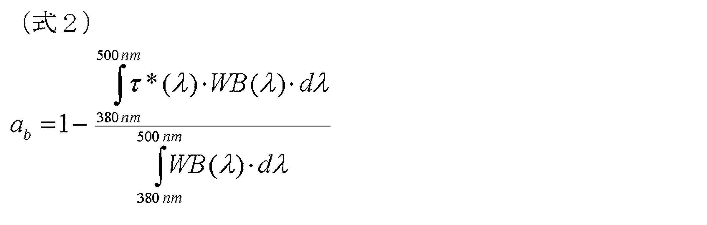
- the blue light absorption rate ab of the spectacle lens is calculated according to the following equation 2.
- WB ( ⁇ ) is a weighting function and is calculated by Equation 3 below.
- E s ⁇ ( ⁇ ) is the spectral irradiance of sunlight
- B ( ⁇ ) is the blue light hazard function.
- E s ⁇ ( ⁇ ), B ( ⁇ ) and WB ( ⁇ ) are described in Appendix C of JIS T 7333.
- the spectrophotometer measures at least from 380 nm to 500 nm at 380 nm, 385 nm, 390 nm... It shall be performed to 500 nm.
- the blue light absorption rate ab of the spectacle lens is obtained by the above formula using the values thus measured at a pitch of 5 nm.
- Bluetooth light absorbing compound refers to a compound having absorption in a wavelength region of 400 to 500 nm.
- the average reflectance in the wavelength range of 400 to 500 nm measured on the eyeball side surface of the spectacle lens and the average reflectance in the wavelength range of 400 to 500 nm measured on the eyeball side surface of the spectacle lens are spectroscopic on each surface. It is an arithmetic average of reflectance measured using a photometer in a wavelength range of 400 to 50 nm.
- the measurement wavelength interval (pitch) can be arbitrarily set. For example, it can be arbitrarily set within the range of 1 to 5 nm.
- the “luminous reflectance” is measured in accordance with JIS T 7334: 2011, and the “luminous transmittance” described later is measured in accordance with JIS T 7333: 2005.
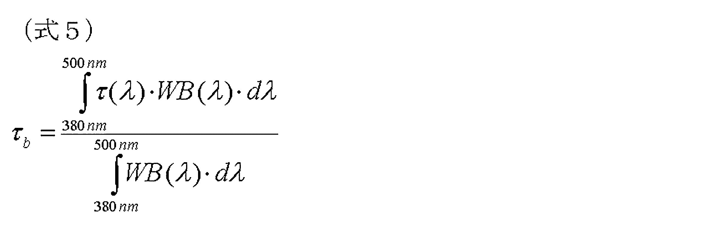
- ⁇ b is a weighted transmittance of blue light harmful to the eyes defined in the standards of the Japan Medical Optical Equipment Manufacturers Association, and is calculated by Expression 5 below.
- WB ( ⁇ ) is calculated by Equation 3 above.
- ⁇ ( ⁇ ) is a transmittance at a wavelength ⁇ nm measured by a spectrophotometer.
- the spectacle lens has an average reflectance in the wavelength range of 400 to 500 nm measured on the object side surface of the spectacle lens in the range of 10.0 to 20.0%, and is measured on the eyeball side surface of the spectacle lens.
- the average reflectance in the wavelength range of 400 to 500 nm is in the range of 10.0 to 20.0%.
- the spectacle lens having a blue light reflectance of 10.0% or more on both sides of the spectacle lens the influence of blue light on the eyes can be effectively reduced.
- the conventional spectacle lens when the reflectance of blue light is increased on both sides of the spectacle lens, the wearing feeling and the appearance of the spectacle lens tend to deteriorate.
- the spectacle lens has a high blue light reflectance of 10.0 to 20.0% on both sides of the spectacle lens, and can realize a good wearing feeling and appearance.
- the average reflectance in the wavelength region of 400 to 500 nm measured on the object side surface of the spectacle lens may be more than 10.0%.
- it is 11.0% or more, more preferably more than 11.0%, still more preferably 12.0% or more, still more preferably more than 12.0%.
- 13.0% or more is even more preferable, 14.0% or more is even more preferable, and 15.0% or more is even more preferable.
- the average reflectance in the wavelength region of 400 to 500 nm measured on the eyeball side surface of the spectacle lens is also more than 10.0%.
- it is 11.0% or more, more preferably more than 11.0%, still more preferably 12.0% or more, still more preferably more than 12.0%.
- 13.0% or more is even more preferable, 14.0% or more is even more preferable, and 15.0% or more is even more preferable.
- the average reflectance in the wavelength region of 400 to 500 nm measured on the object side surface of the spectacle lens is 20.0% or less.
- the average reflectance in the wavelength region of 400 to 500 nm measured on the side surface is also 20.0% or less.
- an average reflectance in a wavelength region of 400 to 500 nm measured on an object side surface of the spectacle lens is 19.5% or less. Is preferably 19.0% or less, more preferably 18.0% or less, still more preferably 17.5% or less, and even more preferably 17.0% or less. Preferably, it is 16.0% or less, still more preferably 15.0% or less, still more preferably 14.0% or less.
- the average reflectance in the wavelength region of 400 to 500 nm measured on the eyeball side surface of the spectacle lens is preferably 19.5% or less. It is more preferably 0% or less, further preferably 18.0% or less, still more preferably 17.5% or less, still more preferably 17.0% or less, and 16.0%. % Or less is even more preferable, 15.0% or less is even more preferable, and 14.0% or less is even more preferable.
- the average reflectance in the wavelength region of 400 to 500 nm measured on the object side surface of the spectacle lens and the average reflectance in the wavelength region of 400 to 500 nm measured on the eyeball side surface may be the same value or different. It may be a value. When the values are different, the average reflectance in the wavelength region of 400 to 500 nm measured on the object side surface of the spectacle lens may be larger than the average reflectance in the wavelength region of 400 to 500 nm measured on the eyeball side surface. It can be small.
- the spectacle lens exhibits high blue light reflectance on both sides of the spectacle lens. Thereby, the influence which blue light has on eyes can be reduced effectively.
- the reason why the glare that causes the wearing feeling and the appearance quality deterioration becomes more noticeable as the blue light reflectance is increased.
- the reason is that the reflectance of so-called green light in the wavelength region adjacent to the wavelength region on the long wavelength side increases.
- the occurrence of glare on the object-side surface exhibiting blue light reflectance in the range of 10.0 to 20.0% and the eyeball-side surface exhibiting blue light reflectance in the range of 10.0 to 20.0% It has become possible to suppress the occurrence of glare in. In this way, by suppressing the occurrence of glare that causes a decrease in wearing comfort and appearance quality, according to the spectacle lens, it is possible to effectively reduce the burden on the eyes caused by blue light, and to provide a good wearing feeling and appearance. Can be realized.
- the luminous reflectance measured on the object side surface of the spectacle lens is preferably 1.8% or less, and 1.5% or less.
- the luminous reflectance measured on the eyeball side surface of the spectacle lens is preferably 1.8% or less, and 1.5% Or less, more preferably 1.3% or less.
- the luminous reflectance measured on the object side surface of the spectacle lens and the luminous reflectance measured on the eyeball side surface are, for example, 0.1% or more, 0.2% or more, 0.3% or more, 0, respectively. Although it can be 4% or more, or 0.5% or more, the above value is an example and is not limited thereto.
- the spectacle lens is a spectacle lens having the reflection characteristics described above and having a blue light absorption rate of 10.0% or more.
- Generation of a double image called a ghost can be suppressed by having a high blue light reflectance on both surfaces of the spectacle lens and a blue light of the spectacle lens being 10.0% or more.
- simply increasing the blue light reflectance on both surfaces of the spectacle lens reduces the feeling of wearing due to the occurrence of ghosts.
- the main cause of the ghost is that blue light incident on the lens without being reflected by the object-side surface of the spectacle lens is multiplexed between the eyeball-side surface and the object-side surface having high blue light reflectance inside the spectacle lens. It is thought to occur due to reflection.
- the blue light absorptivity of the spectacle lens is 10.0% or more, it is possible to suppress the occurrence of ghost in the spectacle lens having an increased blue light reflectance on both sides. This is because the blue light that causes multiple reflection is absorbed much inside the spectacle lens, so that the intensity at which a double image formed by multiple reflection is visually recognized can be lowered, or the intensity is lowered so that it is not visually recognized.
- the blue light absorption rate of the spectacle lens is preferably 12.0% or more, more preferably 13.0% or more, and 14.0% or more. Is more preferably 15.0% or more, and further preferably 15.5% or more. Further, the blue light absorption rate of the spectacle lens can be, for example, 40.0% or less, 30.0% or less, 28.0% or less, or 25.0% or less, but these are merely examples. . From the viewpoint of further suppressing the generation of ghosts, the blue light absorption rate of the spectacle lens is preferably as high as possible. Therefore, it may exceed the value exemplified above.
- the spectacle lens includes a blue light absorbing compound in a lens substrate. This contributes to the spectacle lens exhibiting a high blue light absorption rate of 10.0% or more. Details of the blue light absorbing compound will be described later.
- the spectacle lens includes a multilayer film positioned on the object-side surface of the lens substrate and a multilayer film positioned on the eyeball-side surface of the lens substrate.
- the multilayer film may be directly positioned on the surface of the lens substrate, or may be indirectly positioned on the surface of the lens substrate through one or more other layers.
- Examples of the layer that can be formed between the lens substrate and the multilayer film include a polarizing layer, a light control layer, a hard coat layer (hereinafter also referred to as “hard coat”), and the like. By providing the hard coat layer, the durability (strength) of the spectacle lens can be enhanced.
- the multilayer film provided on the eyeball-side surface and the object-side surface of the lens substrate is not particularly limited as long as the above-described reflection characteristics can be imparted to the spectacle lens surface having the multilayer film.
- Such a multilayer film can be preferably formed by sequentially laminating a high refractive index layer and a low refractive index layer. More specifically, the refractive index of the film material for forming the high refractive index layer and the low refractive index layer and the reflection characteristics (blue light reflectance and luminous reflectance) to be provided to the spectacle lens by providing a multilayer film.
- a multilayer film can be formed.
- a film design that increases the reflectance of blue light and suppresses an increase in the reflectance of green light in a wavelength region adjacent to the wavelength region of blue light (for example, a wavelength region of more than 500 nm and not more than 580 nm) is performed.
- a blue light reflectance in the range of 10.0 to 20.0 nm and a luminous reflectance of less than 2.0% can be provided on each surface of the spectacle lens.
- the film-forming material may be an inorganic material, an organic material, or an organic-inorganic composite material, and an inorganic material is preferable from the viewpoint of film formation and availability.
- the blue light reflectance and luminous reflectance can be controlled by adjusting the kind of film forming material, film thickness, stacking order, and the like.
- Examples of the high refractive index material for forming the high refractive index layer include zirconium oxide (for example, ZrO 2 ), tantalum oxide (Ta 2 O 5 ), titanium oxide (for example, TiO 2 ), and aluminum oxide (Al 2 One or more oxides selected from the group consisting of O 3 ), yttrium oxide (eg, Y 2 O 3 ), hafnium oxide (eg, HfO 2 ), and niobium oxide (eg, Nb 2 O 5 ). Mention may be made of mixtures.
- the low refractive index material for forming the low refractive index layer is an oxide selected from the group consisting of silicon oxide (eg, SiO 2 ), magnesium fluoride (eg, MgF 2 ), and barium fluoride (eg, BaF 2 ). Or a mixture of two or more kinds of fluorides or fluorides.
- oxides and fluorides are shown in stoichiometric composition, but those having oxygen deficient or excessive oxygen or fluorine in the stoichiometric composition are also used for high refractive index materials or low refractive index. It can be used as a material.
- the film thickness of each layer included in the multilayer film can be determined by optical simulation.
- the layer configuration of the multilayer film for example, from the lens substrate side toward the lens outermost surface side, First layer (low refractive index layer) / second layer (high refractive index layer) / third layer (low refractive index layer) / fourth layer (high refractive index layer) / fifth layer (low refractive index layer) / A structure in which the sixth layer (high refractive index layer) / seventh layer (low refractive index layer) are laminated in this order; First layer (high refractive index layer) / second layer (low refractive index layer) / third layer (high refractive index layer) / fourth layer (low refractive index layer) / fifth layer (high refractive index layer) / A structure in which the sixth layer (low refractive index layer) is laminated in this order; First layer (low refractive index layer) / second layer (high refractive index layer) / third layer (low refractive index layer
- a film mainly composed of silicon oxide (low refractive index layer) and a film mainly composed of zirconium oxide (high refractive index layer) Combinations can be mentioned.
- the combination of the film (low refractive index layer) which has silicon oxide as a main component and the film (high refractive index layer) which has niobium oxide as a main component can also be mentioned.
- a multilayer film including at least one laminated structure in which the two-layer coating film of the above combination is adjacent can be exemplified as a preferable example of the multilayer film.
- each of the above layers is a film mainly composed of the above-described high refractive index material or low refractive index material.
- the main component is a component that occupies the most in the coating film, and is usually a component that occupies about 50% by mass to 100% by mass, and further about 90% by mass to 100% by mass.
- Such a film can be formed by performing film formation using a film formation material (for example, an evaporation source) containing the above material as a main component.
- the main components related to the film forming material are the same as described above.
- the coating film and the film forming material may contain a small amount of impurities that are inevitably mixed, and assist other components such as other inorganic substances and film formation as long as the function of the main component is not impaired.
- a known additive component that plays a role may be included.
- the film formation can be performed by a known film formation method, and it is preferably performed by vapor deposition from the viewpoint of easiness of film formation.
- the vapor deposition in the present invention includes a dry method such as a vacuum vapor deposition method, an ion plating method, and a sputtering method.
- a dry method such as a vacuum vapor deposition method, an ion plating method, and a sputtering method.
- an ion beam assist method in which an ion beam is simultaneously irradiated during deposition may be used.
- the above multilayer film is formed by vapor deposition using a coating mainly composed of a conductive oxide, preferably a deposition source mainly composed of a conductive oxide.
- a conductive oxide is generally known as a transparent conductive oxide such as indium oxide, tin oxide, zinc oxide, titanium oxide, and composite oxides thereof from the viewpoint of the transparency of the spectacle lens. It is preferable to use various conductive oxides. Particularly preferable conductive oxides from the viewpoints of transparency and conductivity include tin oxide and indium-tin oxide (ITO).
- a further functional film on the multilayer film.
- a functional film examples include various functional films such as a water-repellent or hydrophilic antifouling film and an antifogging film.
- any known technique can be applied without any limitation.
- the lens substrate on which the multilayer film is provided on the object-side surface and the eyeball-side surface is not particularly limited as long as it includes a blue light absorbing compound.
- the lens substrate can be a plastic lens substrate or a glass lens substrate.
- the glass lens substrate can be, for example, a lens substrate made of inorganic glass.
- the lens base material is preferably a plastic lens base material from the viewpoint that it is lightweight and difficult to break, and that the blue light absorbing compound can be easily introduced.
- Plastic lens base materials include (meth) acrylic resins and other styrene resins, polycarbonate resins, allyl resins, allyl carbonate resins such as diethylene glycol bisallyl carbonate resin (CR-39), vinyl resins, polyester resins, and polyether resins.
- examples thereof include a cured product (generally called a transparent resin) obtained by curing the polymerizable composition contained therein.
- the unstained thing may be used, and the dyed thing (stained lens) may be used.
- the refractive index of the lens substrate is, for example, about 1.60 to 1.75. However, the refractive index of the lens substrate is not limited to this, and may be within the above range or vertically away from the above range.
- the refractive index means a refractive index ne for e-line (wavelength 546.07 nm).
- the spectacle lens may be various lenses such as a single focus lens, a multifocal lens, and a progressive power lens.
- the type of lens is determined by the surface shape of both surfaces of the lens substrate.
- the lens substrate surface may be a convex surface, a concave surface, or a flat surface.
- the object-side surface is convex and the eyeball-side surface is concave.
- the present invention is not limited to this.
- the lens substrate includes a blue light absorbing compound. This contributes to providing the spectacle lens with blue light absorption of 10.0% or more.
- the blue light absorbing compound include various compounds having absorption in the wavelength range of blue light such as a benzotriazole compound, a benzophenone compound, a triazine compound, and an indole compound.
- Preferred blue light absorbing compounds include benzotriazole compounds and Indole compounds can be exemplified, and more preferable blue light absorbing compounds include benzotriazole compounds.
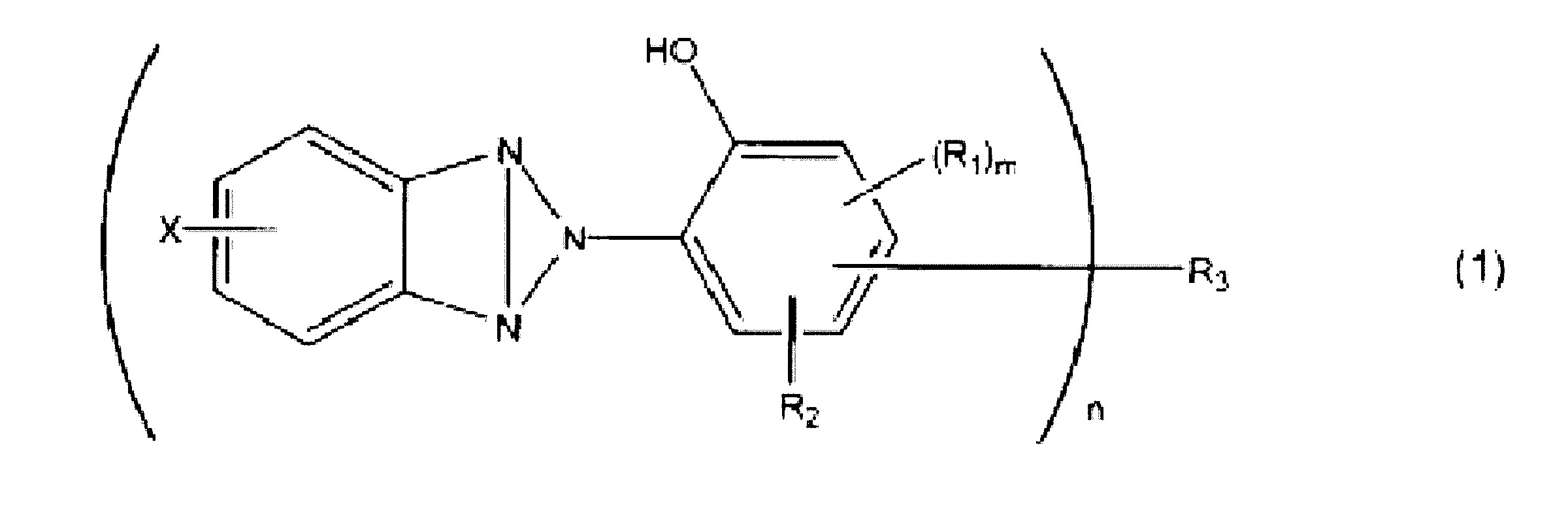
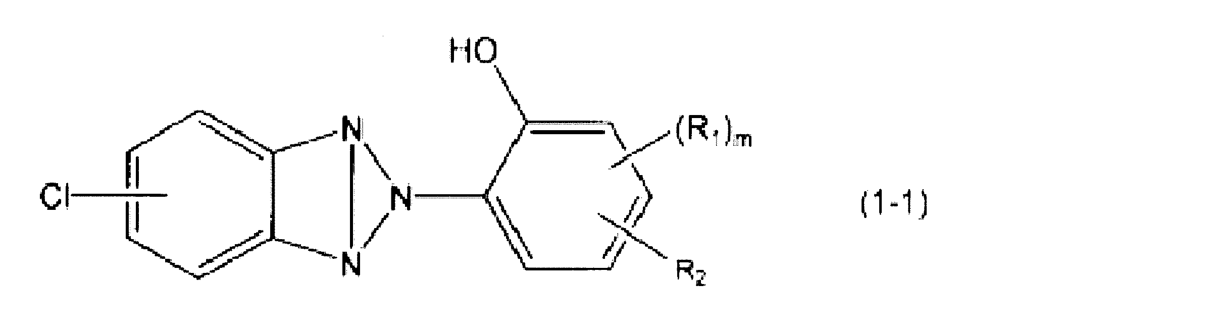
- a benzotriazole compound represented by the following formula (1) is preferable.
- X represents a group imparting a resonance effect.
- the substitution position of X is preferably the 5-position of the triazole ring.
- Examples of X include chlorine atom, bromine atom, fluorine atom, iodine atom, sulfo group, carboxy group, nitrile group, alkoxy group, hydroxy group, amino group. Among these, chlorine atom, bromine atom, fluorine An atom is preferable and a chlorine atom is more preferable.
- R 2 represents an alkyl group having 1 to 12 carbon atoms or an alkoxy group having 1 to 12 carbon atoms, and each of the alkyl group and the alkoxy group preferably has 1 to 8 carbon atoms, and has 2 carbon atoms. To 8 is more preferable, and 4 to 8 carbon atoms are still more preferable.
- the alkyl group and alkoxy group may be branched or linear. Of the alkyl group and alkoxy group, an alkyl group is preferred.
- alkyl groups include methyl, ethyl, n-propyl, iso-propyl, n-butyl, sec-butyl, tert-butyl, pentyl, hexyl, heptyl, n- Examples include octyl group, 1,1,3,3-tetramethylbutyl group, nonyl group, decyl group, undecyl group, dodecyl group and the like.
- n-propyl group, iso-propyl group, n-butyl group , Sec-butyl group, tert-butyl group, and 1,1,3,3-tetramethylbutyl group are preferable, n-butyl group, sec-butyl group, tert-butyl group, and 1 1,3,3-tetramethylbutyl group is more preferable, and tert-butyl group is more preferable.
- alkoxy groups include methoxy, ethoxy, propoxy, butoxy, pentyloxy, hexyloxy, heptyloxy, octyloxy, nonyloxy, decyloxy, undecyloxy, and dodecyloxy groups.
- a butoxy group or an ethoxy group is preferable.
- the substitution position of R 2 is preferably the 3-position, 4-position or 5-position based on the substitution position of the benzotriazolyl group.
- R 1 represents an alkyl group having 1 to 3 carbon atoms or an alkoxy group having 1 to 3 carbon atoms, and specific examples thereof include those in which the number of carbon atoms in the above examples given for R 2 is suitable. To do. Among these, a methyl group or an ethyl group is preferable.
- m represents an integer of 0 or 1.
- the substitution position of R 2 is preferably the 5-position based on the substitution position of the benzotriazolyl group.
- n represents the valence of R 3 and is 1 or 2.
- R 3 represents a hydrogen atom or a divalent hydrocarbon group having 1 to 8 carbon atoms.
- n represents 1, R 3 represents a hydrogen atom, and when n is 2, it represents a divalent hydrocarbon group having 1 to 8 carbon atoms.
- Examples of the hydrocarbon group represented by R 3 include an aliphatic hydrocarbon group and an aromatic hydrocarbon group.
- the hydrocarbon group represented by R 3 has 1 to 8 carbon atoms, preferably 1 to 3 carbon atoms.
- Examples of the divalent hydrocarbon group represented by R 3 include a methanediyl group, an ethanediyl group, a propanediyl group, a benzenediyl group, and a toluenediyl group. Among these, a methanediyl group is preferable.
- the substitution position of R 3 is preferably the 3-position based on the substitution position of the benzotriazolyl group.
- R 3 is preferably a hydrogen atom, and n is 1 in this case.
- the benzotriazole compound is preferably a benzotriazole compound represented by the following formula (1-1).
- R 1 , R 2 and m are as defined above, and examples and preferred embodiments are also the same as above.
- benzotriazole compound represented by the formula (1) examples include methylenebis [3- (5-chloro-2-benzotriazolyl) -5- (1,1,3,3-tetramethylbutyl)- 2-hydroxyphenyl], methylenebis [3- (5-chloro-2-benzotriazolyl) -5- (tert-butyl) -2-hydroxyphenyl], methylenebis [3- (5-chloro-2-benzotria] Zolyl) -5-tert-butyl-2-hydroxyphenyl], methylenebis [3- (5-chloro-2-benzotriazolyl) -5-tert-butyl-2-hydroxyphenyl], methylenebis [3- ( 5-chloro-2-benzotriazolyl) -5-ethoxy-2-hydroxyphenyl], phenylenebis [3- (5-chloro-2-benzotriazolyl) 5- (1,1,3,3-tetramethylbutyl) -2-hydroxyphenyl],
- benzotriazole compound represented by the formula (1-1) examples include 2- (3-tert-butyl-2-hydroxy-5-methylphenyl) -5-chloro-2H-benzotriazole, 2- ( 3-tert-butyl-2-hydroxy-5-ethylphenyl) -5-chloro-2H-benzotriazole, 5-chloro-2- (3,5-dimethyl-2-hydroxyphenyl) -2H-benzotriazole, 5 -Chloro-2- (3,5-diethyl-2-hydroxyphenyl) -2H-benzotriazole, 5-chloro-2- (2-hydroxy-4-methoxyphenyl) -2H-benzotriazole, 5-chloro-2 -(4-Ethoxy-2-hydroxyphenyl) -2H-benzotriazole, 2- (4-butoxy-2-hydroxyphenyl) -5 Chloro 2H-benzotriazole, and 5-chloro-2- (2-hydroxy-4-octyloxy-
- the lens base material contains, for example, 0.05 to 3.00 parts by mass of a blue light absorbing compound with respect to 100 parts by mass of the resin (or polymerizable compound for obtaining the resin) constituting the lens base material. It is preferably 0.05 to 2.50 parts by mass, more preferably 0.10 to 2.00 parts by mass, and still more preferably 0.30 to 2.00 parts by mass. However, since it is sufficient that the blue light absorption rate of the spectacle lens can be 10.0% or more, the content is not limited to the above range.
- a known method can be used as a method for producing a lens substrate containing a blue light absorbing compound.
- a lens substrate containing a blue light absorbing compound by adding a blue light absorbing compound to the polymerizable composition can be obtained.
- the blue light-absorbing dye can be introduced into the lens base material by various wet or dry methods generally used as a dyeing method for the lens base material.
- a dipping method dipping method
- a sublimation dyeing method can be given as an example of a dry method.
- the lens base material may contain various additives that may be generally contained in the lens base material of the spectacle lens.
- the polymerizable composition may be formed, for example, in JP-A-7-063902 and JP-A-7. Described in JP-A-10104101, JP-A-9-208621, JP-A-9-255781, etc., JP-A-1-163012, JP-A-3-281313, etc.
- One or more additives such as an internal mold release agent, antioxidant, fluorescent whitening agent, and bluing agent may be added.
- known techniques can be applied without any limitation.
- the above spectacle lens has a multilayer film having high blue light reflectance on both surfaces, and the blue light absorption rate of the spectacle lens is 10.0% or more, thereby realizing a high blue light cut rate as a spectacle lens. can do.
- the blue light cut rate is preferably 30.0% or more, more preferably 33.0% or more, still more preferably 35.0% or more, and even more preferably 36.0% or more. More preferably, it is 38.0% or more.
- the blue light cut rate can be, for example, 50.0% or less. However, from the viewpoint of reducing the amount of blue light incident on the wearer's eyes, the higher the blue light cut rate, the better.
- the spectacle lens can be a spectacle lens having high luminous transmittance and excellent transparency.
- the luminous transmittance of the spectacle lens is preferably 90.0% or more, more preferably 92.0% or more, and further preferably in the range of 92.5 to 99.0%.
- the further aspect of this invention can also provide the spectacles which have the spectacle lens concerning one aspect
- the spectacle lens is as detailed above.
- the refractive index is a refractive index at a wavelength of 500 nm.
- ⁇ 500 nm.
- the unit of physical film thickness is nm.
- Example 1 Molding of lens base material (lens base material made of thiourethane resin) by cast polymerization 100.00 parts by mass of bis- ( ⁇ -epithiopropyl) sulfide, 2- (3-tert) which is a blue light absorbing compound After stirring 0.40 parts by mass of butyl-2-hydroxy-5-methylphenyl) -5-chloro-2H-benzotriazole, 0.05 part by mass of tetra-n-butylphosphonium bromide was added as a catalyst. The mixture was stirred and mixed for 3 minutes under a reduced pressure of 10 mmHg to prepare a lens monomer composition (polymerizable composition).
- this lens monomer composition was poured into a lens molding mold (0.00D, set to a wall thickness of 1.6 mm) composed of a glass mold and a resin gasket prepared in advance. Polymerization was carried out in an electric furnace at 20 ° C. to 100 ° C. over 20 hours. After completion of the polymerization, the gasket and the mold were removed, and heat treatment was performed at 110 ° C. for 1 hour to obtain a plastic lens (lens substrate). The obtained lens substrate had a convex surface on the object side, a concave surface on the eyeball side, and a refractive index of 1.60.
- the concave side (eyeball side) hard coat surface On the concave side (eyeball side) hard coat surface, a total of seven multilayer deposited films were laminated by ion-assisted deposition under the same conditions to obtain a spectacle lens.
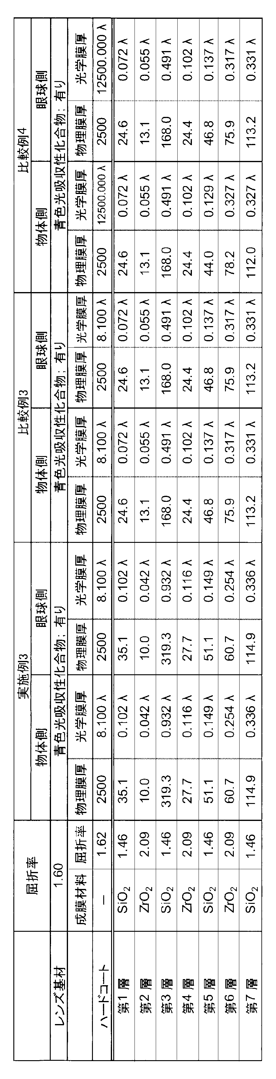
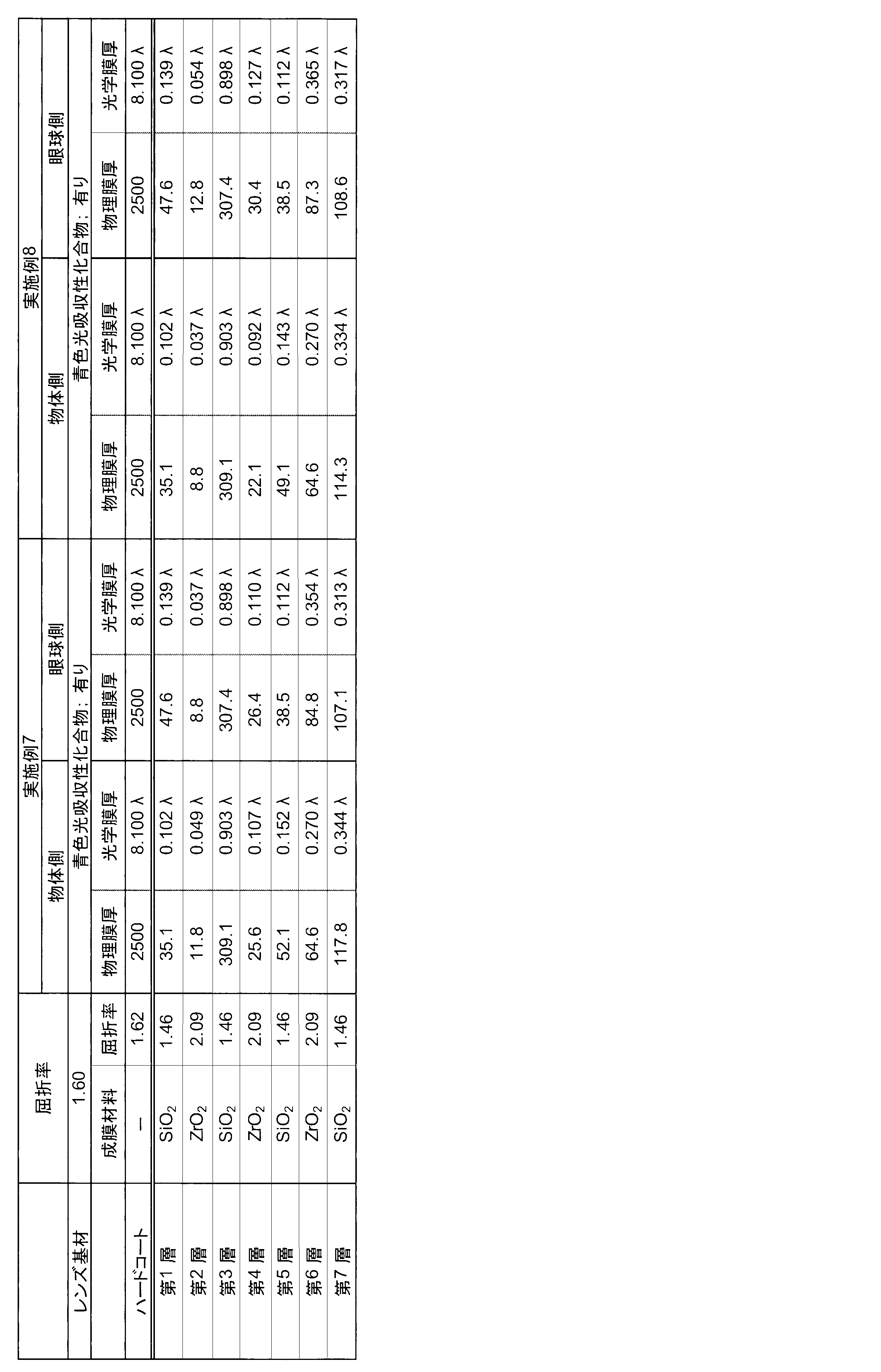
- the multilayer vapor deposition film On both the convex and concave sides, the multilayer vapor deposition film is laminated in the order of the first layer, the second layer, etc., using the vapor deposition source shown in Table 1 from the lens substrate side (hard coat side) to the spectacle lens surface. The outermost layer on the surface side of the spectacle lens was formed to be the seventh layer.
- an evaporation source (film forming material) made of an oxide shown in Table 1 was used except for impurities that could inevitably be mixed. Table 1 shows the refractive index of each oxide and the film thickness of each layer.
- Example 2 (1) Molding of lens substrate (thiourethane resin lens substrate) by cast polymerization Instead of 100.00 parts by mass of bis- ( ⁇ -epithiopropyl) sulfide, 100.00 parts by mass of n-butylthioglycolate A plastic lens (lens substrate) was obtained in the same manner as in Example 1 except that the part was used.
- the obtained lens substrate had a convex surface on the object side, a concave surface on the eyeball side, and a refractive index of 1.67.
- the concave side (eyeball side) hard coat surface On the concave side (eyeball side) hard coat surface, a total of seven multilayer deposited films were laminated by ion-assisted deposition under the same conditions to obtain a spectacle lens.
- the multilayer vapor deposition film On both the convex and concave sides, the multilayer vapor deposition film is laminated in the order of the first layer, the second layer, etc., using the vapor deposition source shown in Table 1 from the lens substrate side (hard coat side) to the spectacle lens surface. The outermost layer on the surface side of the spectacle lens was formed to be the seventh layer.
- lens base material (lens base material made of thiourethane resin) by cast polymerization 100.00 parts by mass of bis- ( ⁇ -epithiopropyl) sulfide, 2- (3-tert) which is a blue light absorbing compound
- 0.05 parts by mass of tetra-n-butylphosphonium bromide was added as a catalyst. The mixture was stirred and mixed for 3 minutes under a reduced pressure of 10 mmHg to prepare a lens monomer composition (polymerizable composition).
- this lens monomer composition was poured into a lens molding mold (0.00D, set to a wall thickness of 1.6 mm) composed of a glass mold and a resin gasket prepared in advance. Polymerization was carried out in an electric furnace at 20 ° C. to 100 ° C. over 20 hours. After completion of the polymerization, the gasket and the mold were removed, and heat treatment was performed at 110 ° C. for 1 hour to obtain a plastic lens (lens substrate). The obtained lens substrate had a convex surface on the object side, a concave surface on the eyeball side, and a refractive index of 1.60.
- the concave side (eyeball side) hard coat surface On the concave side (eyeball side) hard coat surface, a total of seven multilayer deposited films were laminated by ion-assisted deposition under the same conditions to obtain a spectacle lens.
- the multilayer vapor deposition film On both the convex and concave sides, the multilayer vapor deposition film is laminated in the order of the first layer, the second layer, etc., using the vapor deposition source shown in Table 1 from the lens substrate side (hard coat side) to the spectacle lens surface. The outermost layer on the surface side of the spectacle lens was formed to be the seventh layer.
- lens base material (lens base material made of thiourethane resin) by cast polymerization
- tetra-n-butylphosphonium bromide 0 as a catalyst 0.05 parts by mass was added, and the mixture was stirred and mixed for 3 minutes under a reduced pressure of 10 mmHg to prepare a lens monomer composition (polymerizable composition).
- this lens monomer composition was poured into a lens molding mold (0.00D, set to a wall thickness of 1.6 mm) composed of a glass mold and a resin gasket prepared in advance.
- the lens substrate had a convex surface on the object side, a concave surface on the eyeball side, and a refractive index of 1.60.
- the lens base material molded here is a lens base material that does not contain a blue light absorbing compound.
- the concave side (eyeball side) hard coat surface On the concave side (eyeball side) hard coat surface, a total of seven multilayer deposited films were laminated by ion-assisted deposition under the same conditions to obtain a spectacle lens.
- the multilayer vapor deposition film On both the convex and concave sides, the multilayer vapor deposition film is laminated in the order of the first layer, the second layer, etc., using the vapor deposition source shown in Table 1 from the lens substrate side (hard coat side) to the spectacle lens surface. The outermost layer on the surface side of the spectacle lens was formed to be the seventh layer.
- [Comparative Example 2] (1) Molding of lens substrate (thiourethane resin lens substrate) by cast polymerization Instead of 100.00 parts by mass of bis- ( ⁇ -epithiopropyl) sulfide, 100.00 parts by mass of n-butylthioglycolate A plastic lens (lens substrate) was obtained in the same manner as in Comparative Example 1 except that the part was used.
- the obtained lens substrate had a convex surface on the object side, a concave surface on the eyeball side, and a refractive index of 1.67.
- the lens base material molded here is a lens base material that does not contain a blue light absorbing compound.
- the concave side (eyeball side) hard coat surface On the concave side (eyeball side) hard coat surface, a total of seven multilayer deposited films were laminated by ion-assisted deposition under the same conditions to obtain a spectacle lens.
- the multilayer vapor deposition film On both the convex and concave sides, the multilayer vapor deposition film is laminated in the order of the first layer, the second layer, etc., using the vapor deposition source shown in Table 1 from the lens substrate side (hard coat side) to the spectacle lens surface. The outermost layer on the surface side of the spectacle lens was formed to be the seventh layer.
- Example 4 to 8 Comparative Examples 3 and 4
- Molding of lens substrate (thiourethane resin lens substrate) by cast polymerization A plastic lens (lens substrate) was obtained in the same manner as in Example 1.
- the obtained lens substrate had a convex surface on the object side, a concave surface on the eyeball side, and a refractive index of 1.60.
- the concave side (eyeball side) hard coat surface On the concave side (eyeball side) hard coat surface, a total of seven multilayer deposited films were laminated by ion-assisted deposition under the same conditions to obtain a spectacle lens.
- the multilayer vapor deposition film On both the convex and concave sides, the multilayer vapor deposition film is laminated in the order of the first layer, the second layer, etc., using the vapor deposition source shown in Table 1 from the lens substrate side (hard coat side) to the spectacle lens surface. The outermost layer on the surface side of the spectacle lens was formed to be the seventh layer.
- Example 9 Molding of lens substrate (thiourethane resin lens substrate) by cast polymerization A plastic lens (lens substrate) was obtained in the same manner as in Example 2. The obtained lens substrate had a convex surface on the object side, a concave surface on the eyeball side, and a refractive index of 1.67.
- the concave surface (eyeball side) hard coat surface On the concave surface (eyeball side) hard coat surface, a total of five multilayer deposited films were laminated by ion-assisted deposition under the same conditions to obtain a spectacle lens.
- the multilayer vapor deposition film On both the convex and concave sides, the multilayer vapor deposition film is laminated in the order of the first layer, the second layer, etc., using the vapor deposition source shown in Table 1 from the lens substrate side (hard coat side) to the spectacle lens surface. The outermost layer on the spectacle lens surface side was formed to be the fifth layer.
- the multilayer vapor deposition film is formed by using the vapor deposition sources shown in Table 1 (Table 1-1 to Table 1-6) from the lens substrate side (hard coat side) toward the spectacle lens surface.
- the first layer, the second layer, ... were laminated in this order, and the spectacle lens surface outermost layer was formed to be the fifth layer.
- the multilayer deposited film formed in Reference Example 1 is usually a multilayer film formed on a spectacle lens as an antireflection film.
- FIG. 1 shows the reflection spectrum and transmission spectrum of the eyeglass lens of Example 1.
- FIG. 2 shows a reflection spectrum and a transmission spectrum of the spectacle lens of Reference Example 1.
- FIG. 3 shows a reflection spectrum and a transmission spectrum of the eyeglass lens of Comparative Example 1.
- FIG. 4 shows the reflection spectrum and transmission spectrum of the eyeglass lens of Example 2.
- FIG. 5 shows the reflection spectrum and transmission spectrum of the spectacle lens of Comparative Example 2.
- FIG. 6 shows the reflection spectrum and transmission spectrum of the eyeglass lens of Example 3.
- FIG. 7 shows the reflection spectrum and transmission spectrum of the spectacle lens of Comparative Example 3.
- FIG. 8 shows the reflection spectrum and transmission spectrum of the spectacle lens of Comparative Example 4.
- FIG. 9 shows the reflection spectrum and transmission spectrum of the spectacle lens of Example 4.
- FIG. 10 shows the reflection spectrum and transmission spectrum of the eyeglass lens of Example 5.
- FIG. 11 shows the reflection spectrum and transmission spectrum of the spectacle lens of Example 6.
- FIG. 12 shows the reflection spectrum and transmission spectrum of the spectacle lens of Example 7.
- FIG. 13 shows the reflection spectrum and transmission spectrum of the spectacle lens of Example 8.
- FIG. 14 shows the reflection spectrum and transmission spectrum of the eyeglass lens of Example 9. From the comparison of the reflection spectrum and the transmission spectrum of the examples, comparative examples, and reference examples shown in the figure, the spectacle lens of the example has a high blue light reflectance, but the wavelength of the green light adjacent to the blue light wavelength range. It can be confirmed that it has a characteristic reflection spectral characteristic in which the reflectance rapidly decreases in the region.
- Glare evaluation object side
- the eyeglass lenses of Examples, Comparative Examples, and Reference Examples are observed from the object side in a room with normal brightness, and the intensity of glare (light reflected from the object side surface) of the eyeglass lenses of Examples and Comparative Examples is observed by the observer.
- Sensory evaluation was performed with the eyes based on the following evaluation criteria.
- Glare evaluation eyeball side
- the eyeglass lenses of Examples, Comparative Examples, and Reference Examples are observed from the eyeball side in a room with normal brightness, and the intensity of glare (light reflected from the side of the eyeball) of the eyeglass lenses of Examples and Comparative Examples is observed by the observer.
- Sensory evaluation was performed with the eyes based on the following evaluation criteria.
- B Compared with the eyeglass lens of Comparative Example 1, the glare is clearly felt.
- the spectacle lens of the example has a high blue light reflectance of 10.0 to 20.0% on the object side surface and the eyeball side surface, but the occurrence of ghost and glare is suppressed. Can be confirmed. It can also be confirmed that the spectacle lens of the example has a high blue light cut rate, and is a spectacle lens with high luminous transmittance and excellent transparency.
- a spectacle lens including a lens base material, a multilayer film located on an object side surface of the lens base material, and a multilayer film located on an eyeball side surface of the lens base material,
- the light absorptance is 10.0% or more
- the lens substrate contains a blue light absorbing compound, and the average reflection in the wavelength range of 400 to 500 nm measured on the object side surface and the eyeball side surface of the spectacle lens, respectively.
- a spectacle lens is provided in which the rate is in the range of 10.0 to 20.0%, and the luminous reflectance measured on the object side surface and the eyeball side surface of the spectacle lens, respectively, is less than 2.0%.
- the spectacle lens has high blue light reflectance on the object side surface and eyeball side surface of the spectacle lens, it is possible to suppress the occurrence of ghost and glare. Thereby, a good wearing feeling and appearance can be realized.
- the blue light cut rate of the spectacle lens is 30.0% or more.
- the blue light cut rate of the spectacle lens is 36.0% or more.
- the luminous reflectance measured on the object side surface and the eyeball side surface of the spectacle lens is 1.8% or less.
- the average reflectance in the wavelength region of 400 to 500 nm measured on the object side surface and the eyeball side surface of the spectacle lens is in the range of 15.0 to 20.0%.
- the average reflectance in the wavelength region of 400 to 500 nm measured on at least one of the object side surface and the eyeball side surface of the spectacle lens is more than 10.0% and not more than 19.0%.
- the average reflectance in the wavelength region of 400 to 500 nm measured on the object side surface and the eyeball side surface of the spectacle lens is more than 10.0% and not more than 19.0%.
- the average reflectance in the wavelength region of 400 to 500 nm measured on at least one of the object side surface and the eyeball side surface of the spectacle lens is more than 10.0% and not more than 18.0%.
- the average reflectance in the wavelength region of 400 to 500 nm measured on the object side surface and the eyeball side surface of the spectacle lens is more than 10.0% and not more than 18.0%.
- the average reflectance in the wavelength region of 400 to 500 nm measured on at least one of the object side surface and the eyeball side surface of the spectacle lens is more than 10.0% and not more than 17.5%.
- the average reflectance in the wavelength region of 400 to 500 nm measured on the object side surface and the eyeball side surface of the spectacle lens is more than 10.0% and not more than 17.5%.
- the average reflectance in the wavelength region of 400 to 500 nm measured on at least one of the object side surface and the eyeball side surface of the spectacle lens is more than 10.0% and not more than 17.0%.
- the average reflectance in the wavelength region of 400 to 500 nm measured on the object side surface and the eyeball side surface of the spectacle lens is more than 10.0% and not more than 17.0%.
- the average reflectance in the wavelength region of 400 to 500 nm measured on at least one of the object-side surface and the eyeball-side surface of the spectacle lens is more than 10.0% and not more than 16.0%.
- the average reflectance in the wavelength region of 400 to 500 nm measured on the object side surface and the eyeball side surface of the spectacle lens is more than 10.0% and not more than 16.0%.
- the average reflectance in the wavelength region of 400 to 500 nm measured on at least one of the object side surface and the eyeball side surface of the spectacle lens is more than 11.0% and not more than 16.0%.
- the average reflectance in the wavelength region of 400 to 500 nm measured on the object side surface and the eyeball side surface of the spectacle lens is more than 11.0% and not more than 16.0%.
- the average reflectance in the wavelength region of 400 to 500 nm measured on at least one of the object side surface and the eyeball side surface of the spectacle lens is more than 12.0% and not more than 16.0%.
- the average reflectance in the wavelength region of 400 to 500 nm measured on the object side surface and the eyeball side surface of the spectacle lens is more than 12.0% and not more than 16.0%.
- the blue light absorbing compound is a benzotriazole compound.
- the multilayer film located on the object side surface of the lens base material and the multilayer film located on the eyeball side surface of the lens base material are multilayer films having a plurality of coatings containing an inorganic material as a main component. .
- the multilayer film located on the object-side surface of the lens base material and the multilayer film located on the eyeball-side surface of the lens base material mainly comprise a coating containing silicon oxide as a main component and zirconium oxide. It has at least one laminated structure adjacent to the coating film contained as a component.
- the luminous transmittance of the spectacle lens is 90.0% or more.
- spectacles having the spectacle lens and a frame to which the spectacle lens is attached.
- the present invention is useful in the field of manufacturing eyeglass lenses and eyeglasses.
Landscapes
- Physics & Mathematics (AREA)
- General Physics & Mathematics (AREA)
- Optics & Photonics (AREA)
- Health & Medical Sciences (AREA)
- Ophthalmology & Optometry (AREA)
- General Health & Medical Sciences (AREA)
- Spectroscopy & Molecular Physics (AREA)
- Eyeglasses (AREA)
- Optical Filters (AREA)
- Surface Treatment Of Optical Elements (AREA)
Abstract
Description
一方で、眼鏡レンズには、眼鏡装用者が良好な装用感をもって使用可能であること、および外観が良好であることも望まれる。しかるに、眼鏡レンズ両面における青色光の反射率を高めるほど、眼鏡レンズを介して装用者の眼に入射する青色光の光量を低減できるものの、眼鏡レンズの装用感および外観は劣化する傾向がある。
レンズ基材と、レンズ基材の物体側表面上に位置する多層膜と、レンズ基材の眼球側表面上に位置する多層膜と、を含む眼鏡レンズであって、
青色光吸収率が10.0%以上であり、
上記レンズ基材は、青色光吸収性化合物を含み、
眼鏡レンズの物体側表面および眼球側表面においてそれぞれ測定される400~500nmの波長域における平均反射率は10.0~20.0%の範囲であり、かつ眼鏡レンズの物体側表面および眼球側表面においてそれぞれ測定される視感反射率は2.0%未満である眼鏡レンズ、
に関する。
上記眼鏡レンズは、レンズ基材の物体側表面上および眼球側表面上に、それぞれ多層膜を有する。即ち、眼鏡レンズの両面に多層膜を有する。そして、眼鏡レンズの物体側表面および眼球側表面においてそれぞれ測定される400~500nmの波長域における平均反射率(以下、「青色光反射率」ともいう。)が、10.0~20.0%の範囲である。これにより、上記眼鏡レンズは、その両面においてそれぞれ青色光を高い反射率で反射することができる。しかし従来、眼鏡レンズの両面に多層膜を設けて高い青色光反射率を達成しようとすると、得られる眼鏡レンズは、装用感および外観に劣るものとなる傾向があった。これは、ゴーストと呼ばれる二重像が発生すること、および眼鏡レンズの両面にギラツキが発生することが理由であった。
これに対し上記眼鏡レンズは、レンズ基材に青色光吸収性化合物を含み、かつ眼鏡レンズの青色光吸収率が10.0%以上である。これによりゴーストの発生を抑制することが可能になる。詳細は更に後述する。
また、装用感および外観に関しては、眼鏡レンズの物体側表面におけるギラツキの発生は、眼鏡レンズの外観品質低下の原因となる。眼鏡装用者に対向した第三者が眼鏡装用者の外観に違和感(不自然な反射)を感じることにつながるからである。また、眼鏡レンズの眼球側表面におけるギラツキの発生は、眼鏡装用者が感じる装用感が低下する(不自然な反射を感じる)原因になる。これに対し、上記眼鏡レンズは、眼鏡レンズ両面で高い青色光反射率を有するにもかかわらず、両面で測定される視感反射率が、それぞれ2.0%未満である。これにより、眼鏡レンズの物体側表面におけるギラツキおよび眼球側表面におけるギラツキの発生を、それぞれ抑制することが可能となる。
本発明の一態様にかかる眼鏡レンズは、レンズ基材と、レンズ基材の眼球側表面上に位置する多層膜と、レンズ基材の物体側表面上に位置する多層膜と、を含む眼鏡レンズであって、青色光吸収率が10.0%以上であり、上記レンズ基材は、青色光吸収性化合物を含み、眼鏡レンズの物体側表面および眼球側表面においてそれぞれ測定される400~500nmの波長域における平均反射率は10.0~20.0%の範囲であり、かつ眼鏡レンズの物体側表面および眼球側表面においてそれぞれ測定される視感反射率は2.0%未満である。
分光光度計によって波長380nm~500nmの波長域における透過率および反射率を測定する。本発明および本明細書において、反射、透過または吸収を求める測定光は直入射光をいうものとする。したがって、上記の透過率および反射率は、直入射光に対する透過率および反射率である。また、測定は光学中心において行う。特記しない限り、測定にあたり、測定波長間隔(ピッチ)は任意に設定可能である。例えば、1~5nmの範囲で任意に設定可能である。分光光度計により測定される透過率には、入射光の中で、眼鏡レンズの表面において反射される成分は考慮されていない。したがって、眼鏡レンズが吸収した光と同様に、眼鏡レンズ表面で反射されレンズ内に入射していない光も、分光光度計による測定では、透過量の減少として観測される。そこで、反射の影響を差し引いた波長λnmにおける透過率τ*(λ)を、下記式1により算出する。

(式4)
青色光カット率Cb=1-τb
(400~500nmの波長域における平均反射率(青色光反射率))
上記眼鏡レンズは、眼鏡レンズの物体側表面において測定される400~500nmの波長域における平均反射率が10.0~20.0%の範囲であり、かつ眼鏡レンズの眼球側表面において測定される400~500nmの波長域における平均反射率が10.0~20.0%の範囲である。眼鏡レンズの両面において、それぞれ10.0%以上の青色光反射率を有する眼鏡レンズによれば、青色光が眼に与える影響を効果的に軽減することができる。しかるに従来の眼鏡レンズでは、眼鏡レンズ両面において青色光の反射率を高めようとすると、眼鏡レンズの装用感および外観が劣化する傾向があった。これに対し上記眼鏡レンズは、眼鏡レンズ両面における青色光反射率がそれぞれ10.0~20.0%と高く、かつ良好な装用感および外観を実現することができる。高い青色光反射率と良好な装用感および外観を共に実現できる理由について、詳細は後述する。
一態様では、青色光が眼に与える影響をより一層低減する観点から、眼鏡レンズの物体側表面において測定される400~500nmの波長域における平均反射率は、10.0%超であることが好ましく、11.0%以上であることがより好ましく、11.0%超であることが更に好ましく、12.0%以上であることが一層好ましく、12.0%超であることがより一層好ましく、13.0%以上であることが更に一層好ましく、14.0%以上であることがなおより一層好ましく、15.0%以上であることが更により一層好ましい。
一態様では、青色光が眼に与える影響をより一層低減する観点から、眼鏡レンズの眼球側表面において測定される400~500nmの波長域における平均反射率も、10.0%超であることが好ましく、11.0%以上であることがより好ましく、11.0%超であることが更に好ましく、12.0%以上であることが一層好ましく、12.0%超であることがより一層好ましく、13.0%以上であることが更に一層好ましく、14.0%以上であることがなおより一層好ましく、15.0%以上であることが更により一層好ましい。
一方、良好な装用感を実現するために、上記眼鏡レンズにおいて、眼鏡レンズの物体側表面において測定される400~500nmの波長域における平均反射率は20.0%以下であり、眼鏡レンズの眼球側表面において測定される400~500nmの波長域における平均反射率も20.0%以下である。一態様では、より良好な装用感を実現する観点から、上記眼鏡レンズにおいて、眼鏡レンズの物体側表面において測定される400~500nmの波長域における平均反射率は、19.5%以下であることが好ましく、19.0%以下であることがより好ましく、18.0%以下であることが更に好ましく、17.5%以下であることが一層好ましく、17.0%以下であることがより一層好ましく、16.0%以下であることが更に一層好ましく、15.0%以下であることがなおより一層好ましく、14.0%以下であることが更により一層好ましい。一態様では、より良好な装用感を実現する観点から、眼鏡レンズの眼球側表面において測定される400~500nmの波長域における平均反射率は、19.5%以下であることが好ましく、19.0%以下であることがより好ましく、18.0%以下であることが更に好ましく、17.5%以下であることが一層好ましく、17.0%以下であることがより一層好ましく、16.0%以下であることが更に一層好ましく、15.0%以下であることがなおより一層好ましく、14.0%以下であることが更により一層好ましい。
眼鏡レンズの物体側表面において測定される400~500nmの波長域における平均反射率と眼球側表面において測定される400~500nmの波長域における平均反射率とは、同じ値であってもよく、異なる値であってもよい。異なる値である場合、眼鏡レンズの物体側表面において測定される400~500nmの波長域における平均反射率が、眼球側表面において測定される400~500nmの波長域における平均反射率より大きくてもよく、小さくてもよい。
上記眼鏡レンズは、眼鏡レンズの両面において、それぞれ高い青色光反射率を示す。これにより青色光が眼に与える影響を効果的に低減することができる。この点に関して本発明者らは検討を重ねる中で、従来の多層膜の膜設計では、青色光反射率を高めるほど装用感および外観品質低下の原因となるギラツキが顕著になる理由は、青色光の波長域に長波長側で隣接する波長域にある所謂緑色光の反射率が上昇することが原因と考えるに至った。そして、青色光反射率が10.0~20.0%の範囲で緑色光の反射率上昇を抑制するという、従来とは異なる膜設計を行うことにより、視感反射率を低く抑えることが可能となった。そしてこれにより、10.0~20.0%の範囲の青色光反射率を示す物体側表面におけるギラツキの発生、および10.0~20.0%の範囲の青色光反射率を示す眼球側表面におけるギラツキの発生を、共に抑制することが可能になった。こうして装用感および外観品質の低下の原因となるギラツキの発生を抑制することにより、上記眼鏡レンズによれば、青色光による眼への負担を効果的に軽減できるとともに、良好な装用感および外観を実現することができる。
外観品質低下につながる物体側表面におけるギラツキの更なる抑制の観点から、眼鏡レンズの物体側表面において測定される視感反射率は1.8%以下であることが好ましく、1.5%以下であることがより好ましく、1.3%以下であることがより好ましい。一方、装用感低下につながる眼球側表面におけるギラツキの更なる抑制の観点から、眼鏡レンズの眼球側表面において測定される視感反射率は1.8%以下であることが好ましく、1.5%以下であることがより好ましく、1.3%以下であることがより好ましい。
眼鏡レンズの物体側表面において測定される視感反射率および眼球側表面において測定される視感反射率は、それぞれ、例えば0.1%以上、0.2%以上、0.3%以上、0.4%以上、または0.5%以上であることができるが、上記値は例示であって、これらに限定されるものではない。
上記眼鏡レンズは、以上説明した反射特性を有し、かつ青色光吸収率が10.0%以上の眼鏡レンズである。眼鏡レンズ両面で高い青色光反射率を有するとともに、眼鏡レンズの青色光が10.0%以上であることによって、ゴーストと呼ばれる二重像の発生を抑制することができる。これに対し、単に眼鏡レンズ両面で青色光反射率を高めるのみでは、ゴーストの発生によって装用感が低下してしまう。
上記眼鏡レンズは、レンズ基材の物体側表面上に位置する多層膜およびレンズ基材の眼球側表面上に位置する多層膜を含む。上記多層膜は、レンズ基材の表面上に直接位置してもよく、一層以上の他の層を介して間接的にレンズ基材の表面上に位置してもよい。レンズ基材と上記多層膜との間に形成され得る層としては、例えば、偏光層、調光層、ハードコート層(以下、「ハードコート」とも記載する。)等を挙げることができる。ハードコート層を設けることにより眼鏡レンズの耐久性(強度)を高めることもできる。ハードコート層の詳細については、例えば特開2012-128135号公報の段落0025~0028、0030を参照できる。また、レンズ基材と上記多層膜との間には、密着性向上のためのプライマー層を形成してもよい。プライマー層の詳細については、例えば特開2012-128135号公報の段落0029~0030を参照できる。
第一層(低屈折率層)/第二層(高屈折率層)/第三層(低屈折率層)/第四層(高屈折率層)/第五層(低屈折率層)/第六層(高屈折率層)/第七層(低屈折率層)の順に積層された構成;
第一層(高屈折率層)/第二層(低屈折率層)/第三層(高屈折率層)/第四層(低屈折率層)/第五層(高屈折率層)/第六層(低屈折率層)の順に積層された構成;
第一層(低屈折率層)/第二層(高屈折率層)/第三層(低屈折率層)/第四層(高屈折率層)/第五層(低屈折率層)の順に積層された構成;
等を挙げることができる。好ましい低屈折率層と高屈折率層の組み合わせの一例としては、ケイ素酸化物を主成分とする被膜(低屈折率層)とジルコニウム酸化物を主成分とする被膜(高屈折率層)との組み合わせを挙げることができる。また、ケイ素酸化物を主成分とする被膜(低屈折率層)とニオブ酸化物を主成分とする被膜(高屈折率層)との組み合わせを挙げることもできる。上記組み合わせの二層の被膜が隣接する積層構造を少なくとも1つ含む多層膜を、多層膜の好ましい一例として例示することができる。
上記多層膜が物体側表面上および眼球側表面上にそれぞれ設けられるレンズ基材は、青色光吸収性化合物を含むものである限り、特に限定されない。レンズ基材は、プラスチックレンズ基材またはガラスレンズ基材であることができる。ガラスレンズ基材は、例えば無機ガラス製のレンズ基材であることができる。レンズ基材は、軽量で割れ難く、かつ青色光吸収性化合物の導入が容易であるという観点から、プラスチックレンズ基材が好ましい。プラスチックレンズ基材としては、(メタ)アクリル樹脂をはじめとするスチレン樹脂、ポリカーボネート樹脂、アリル樹脂、ジエチレングリコールビスアリルカーボネート樹脂(CR-39)等のアリルカーボネート樹脂、ビニル樹脂、ポリエステル樹脂、ポリエーテル樹脂、イソシアネート化合物とジエチレングリコールなどのヒドロキシ化合物との反応で得られたウレタン樹脂、イソシアネート化合物とポリチオール化合物とを反応させたチオウレタン樹脂、分子内に1つ以上のジスルフィド結合を有する(チオ)エポキシ化合物を含有する重合性組成物を硬化した硬化物(一般に透明樹脂と呼ばれる。)を挙げることができる。なおレンズ基材としては、染色されていないもの(無色レンズ)を用いてもよく、染色されているもの(染色レンズ)を用いてもよい。レンズ基材の屈折率は、例えば、1.60~1.75程度である。ただしレンズ基材の屈折率は、これに限定されるものではなく、上記の範囲内でも、上記の範囲から上下に離れていてもよい。なお屈折率とは、e線(波長546.07nm)に対する屈折率neをいうものとする。
上記レンズ基材は、青色光吸収性化合物を含む。このことが、上記眼鏡レンズに10.0%以上の青色光吸収率をもたらすことに寄与する。青色光吸収性化合物は、ベンゾトリアゾール化合物、ベンゾフェノン化合物、トリアジン化合物、インドール化合物等の青色光の波長域に吸収を有する各種化合物を挙げることができ、好ましい青色光吸収性化合物としてはベンゾトリアゾール化合物およびインドール化合物を挙げることができ、より好ましい青色光吸収性化合物としてはベンゾトリアゾール化合物を挙げることができる。ベンゾトリアゾール化合物としては、下記式(1)で表されるベンゾトリアゾール化合物が好ましい。
Xの例としては、塩素原子、臭素原子、フッ素原子、ヨウ素原子、スルホ基、カルボキシ基、ニトリル基、アルコキシ基、ヒドロキシ基、アミノ基が挙げられ、これらの中でも、塩素原子、臭素原子、フッ素原子が好ましく、塩素原子がより好ましい。
アルキル基およびアルコキシ基は、分岐であっても直鎖であってもよい。アルキル基およびアルコキシ基の中でも、アルキル基が好ましい。
式(1)において、R2の置換位置は、ベンゾトリアゾリル基の置換位置を基準として、3位,4位または5位が好ましい。
R3で表される2価の炭化水素基の例としては、メタンジイル基、エタンジイル基、プロパンジイル基、ベンゼンジイル基、トルエンジイル基等が挙げられ、これらの中でもメタンジイル基が好ましい。
更に上記眼鏡レンズは、一態様では、高い視感透過率を有する透明性に優れた眼鏡レンズであることができる。上記眼鏡レンズの視感透過率は、好ましくは90.0%以上であり、より好ましくは92.0%以上であり、更に好ましくは92.5~99.0%の範囲である。
本発明の更なる態様は、上記の本発明の一態様にかかる眼鏡レンズと、この眼鏡レンズを取り付けたフレームとを有する眼鏡を提供することもできる。眼鏡レンズについては、先に詳述した通りである。かかる眼鏡レンズを備えることにより、上記眼鏡によって、青色光が装用者の眼に与える影響を効果的に軽減することができる。その他の眼鏡の構成については、特に制限はなく、公知技術を適用することができる。
(1)注型重合によるレンズ基材(チオウレタン樹脂製レンズ基材)の成形
ビス-(β-エピチオプロピル)スルフィド100.00質量部、青色光吸収性化合物である2-(3-tertブチル-2-ヒドロキシ-5-メチルフェニル)-5-クロロ-2H-ベンゾトリアゾール0.40質量部を攪拌混合した後、触媒としてテトラ-n-ブチルホスホニュウムブロマイド0.05質量部を添加し、10mmHgの減圧下で3分間攪拌混合し、レンズ用モノマー組成物(重合性組成物)を調製した。次いで、このレンズ用モノマー組成物を、予め準備したガラス製モールドと樹脂製ガスケットから構成されるレンズ成型用鋳型(0.00D、肉厚1.6mmに設定)の中に注入し、炉内温度20℃~100℃の電気炉中で20時間かけて重合を行った。重合終了後、ガスケットおよびモールドを取り外した後、110℃で1時間熱処理してプラスチックレンズ(レンズ基材)を得た。得られたレンズ基材は、物体側表面が凸面、眼球側表面が凹面、屈折率は1.60であった。
上記レンズ基材の両面を光学面に加工(研磨)した後に、ハードコートを形成した。ハードコート層は、表1に示す厚みを有し、屈折率は1.62であった。
こうして得られた両面が光学的に仕上げられ予めハードコートが施された、物体側表面が凸面、眼球側表面が凹面であるレンズ基材の凸面側(物体側)のハードコート表面に、アシストガスとして酸素ガスおよび窒素ガスを用いて、イオンアシスト蒸着に合計7層の多層蒸着膜を順次形成した。
凹面側(眼球側)のハードコート表面にも同様の条件でイオンアシスト蒸着により合計7層の多層蒸着膜を積層して眼鏡レンズを得た。
凸面側、凹面側とも、多層蒸着膜は、レンズ基材側(ハードコート側)から眼鏡レンズ表面に向かって、表1に示す蒸着源を用いて第1層、第2層…の順に積層し、眼鏡レンズ表面側最外層が第7層となるように形成した。
本実施例では、不可避的に混入する可能性のある不純物を除けば表1に示す酸化物からなる蒸着源(成膜材料)を使用した。各酸化物の屈折率および各層の膜厚を表1に示す。これらの点は、後述の実施例および比較例についても、同様である。
(1)注型重合によるレンズ基材(チオウレタン樹脂製レンズ基材)の成形
ビス-(β-エピチオプロピル)スルフィド100.00質量部に代えて、n-ブチルチオグリコレート100.00質量部を用いた点以外、実施例1と同様の方法でプラスチックレンズ(レンズ基材)を得た。得られたレンズ基材は、物体側表面が凸面、眼球側表面が凹面、屈折率は1.67であった。
上記レンズ基材の両面を光学面に加工(研磨)した後に、ハードコートを形成した。ハードコート層は、表1に示す厚みを有し、屈折率は1.68であった。
こうして得られた両面が光学的に仕上げられ予めハードコートが施された、物体側表面が凸面、眼球側表面が凹面であるレンズ基材の凸面側(物体側)のハードコート表面に、アシストガスとして酸素ガスおよび窒素ガスを用いて、イオンアシスト蒸着に合計7層の多層蒸着膜を順次形成した。
凹面側(眼球側)のハードコート表面にも同様の条件でイオンアシスト蒸着により合計7層の多層蒸着膜を積層して眼鏡レンズを得た。
凸面側、凹面側とも、多層蒸着膜は、レンズ基材側(ハードコート側)から眼鏡レンズ表面に向かって、表1に示す蒸着源を用いて第1層、第2層…の順に積層し、眼鏡レンズ表面側最外層が第7層となるように形成した。
(1)注型重合によるレンズ基材(チオウレタン樹脂製レンズ基材)の成形
ビス-(β-エピチオプロピル)スルフィド100.00質量部、青色光吸収性化合物である2-(3-tertブチル-2-ヒドロキシ-5-メチルフェニル)-5-クロロ-2H-ベンゾトリアゾール0.10質量部を攪拌混合した後、触媒としてテトラ-n-ブチルホスホニュウムブロマイド0.05質量部を添加し、10mmHgの減圧下で3分間攪拌混合し、レンズ用モノマー組成物(重合性組成物)を調製した。次いで、このレンズ用モノマー組成物を、予め準備したガラス製モールドと樹脂製ガスケットから構成されるレンズ成型用鋳型(0.00D、肉厚1.6mmに設定)の中に注入し、炉内温度20℃~100℃の電気炉中で20時間かけて重合を行った。重合終了後、ガスケットおよびモールドを取り外した後、110℃で1時間熱処理してプラスチックレンズ(レンズ基材)を得た。得られたレンズ基材は、物体側表面が凸面、眼球側表面が凹面、屈折率は1.60であった。
上記レンズ基材の両面を光学面に加工(研磨)した後に、ハードコートを形成した。ハードコート層は、表1に示す厚みを有し、屈折率は1.62であった。
こうして得られた両面が光学的に仕上げられ予めハードコートが施された、物体側表面が凸面、眼球側表面が凹面であるレンズ基材の凸面側(物体側)のハードコート表面に、アシストガスとして酸素ガスおよび窒素ガスを用いて、イオンアシスト蒸着に合計7層の多層蒸着膜を順次形成した。
凹面側(眼球側)のハードコート表面にも同様の条件でイオンアシスト蒸着により合計7層の多層蒸着膜を積層して眼鏡レンズを得た。
凸面側、凹面側とも、多層蒸着膜は、レンズ基材側(ハードコート側)から眼鏡レンズ表面に向かって、表1に示す蒸着源を用いて第1層、第2層…の順に積層し、眼鏡レンズ表面側最外層が第7層となるように形成した。
(1)注型重合によるレンズ基材(チオウレタン樹脂製レンズ基材)の成形
ビス-(β-エピチオプロピル)スルフィド100.00質量部に、触媒としてテトラ-n-ブチルホスホニュウムブロマイド0.05質量部を添加し、10mmHgの減圧下で3分間攪拌混合し、レンズ用モノマー組成物(重合性組成物)を調製した。次いで、このレンズ用モノマー組成物を、予め準備したガラス製モールドと樹脂製ガスケットから構成されるレンズ成型用鋳型(0.00D、肉厚1.6mmに設定)の中に注入し、炉内温度20℃~100℃の電気炉中で20時間かけて重合を行った。重合終了後、ガスケットおよびモールドを取り外した後、110℃で1時間熱処理してプラスチックレンズ(レンズ基材)を得た。得られたレンズ基材は、物体側表面が凸面、眼球側表面が凹面、屈折率は1.60であった。ここで成形されたレンズ基材は、青色光吸収性化合物を含まないレンズ基材である。
上記レンズ基材の両面を光学面に加工(研磨)した後に、ハードコートを形成した。ハードコート層は、表1に示す厚みを有し、屈折率は1.62であった。
こうして得られた両面が光学的に仕上げられ予めハードコートが施された、物体側表面が凸面、眼球側表面が凹面であるレンズ基材の凸面側(物体側)のハードコート表面に、アシストガスとして酸素ガスおよび窒素ガスを用いて、イオンアシスト蒸着に合計7層の多層蒸着膜を順次形成した。
凹面側(眼球側)のハードコート表面にも同様の条件でイオンアシスト蒸着により合計7層の多層蒸着膜を積層して眼鏡レンズを得た。
凸面側、凹面側とも、多層蒸着膜は、レンズ基材側(ハードコート側)から眼鏡レンズ表面に向かって、表1に示す蒸着源を用いて第1層、第2層…の順に積層し、眼鏡レンズ表面側最外層が第7層となるように形成した。
(1)注型重合によるレンズ基材(チオウレタン樹脂製レンズ基材)の成形
ビス-(β-エピチオプロピル)スルフィド100.00質量部に代えて、n-ブチルチオグリコレート100.00質量部を用いた点以外、比較例1と同様の方法でプラスチックレンズ(レンズ基材)を得た。得られたレンズ基材は、物体側表面が凸面、眼球側表面が凹面、屈折率は1.67であった。ここで成形されたレンズ基材は、青色光吸収性化合物を含まないレンズ基材である。
上記レンズ基材の両面を光学面に加工(研磨)した後に、ハードコートを形成した。ハードコート層は、表1に示す厚みを有し、屈折率は1.68であった。
こうして得られた両面が光学的に仕上げられ予めハードコートが施された、物体側表面が凸面、眼球側表面が凹面であるレンズ基材の凸面側(物体側)のハードコート表面に、アシストガスとして酸素ガスおよび窒素ガスを用いて、イオンアシスト蒸着に合計7層の多層蒸着膜を順次形成した。
凹面側(眼球側)のハードコート表面にも同様の条件でイオンアシスト蒸着により合計7層の多層蒸着膜を積層して眼鏡レンズを得た。
凸面側、凹面側とも、多層蒸着膜は、レンズ基材側(ハードコート側)から眼鏡レンズ表面に向かって、表1に示す蒸着源を用いて第1層、第2層…の順に積層し、眼鏡レンズ表面側最外層が第7層となるように形成した。
(1)注型重合によるレンズ基材(チオウレタン樹脂製レンズ基材)の成形
実施例1と同様の方法で、プラスチックレンズ(レンズ基材)を得た。得られたレンズ基材は、物体側表面が凸面、眼球側表面が凹面、屈折率は1.60であった。
上記レンズ基材の両面を光学面に加工(研磨)した後に、ハードコートを形成した。ハードコート層は、表1に示す厚みを有し、屈折率は1.62であった。
こうして得られた両面が光学的に仕上げられ予めハードコートが施された、物体側表面が凸面、眼球側表面が凹面であるレンズ基材の凸面側(物体側)のハードコート表面に、アシストガスとして酸素ガスおよび窒素ガスを用いて、イオンアシスト蒸着に合計7層の多層蒸着膜を順次形成した。
凹面側(眼球側)のハードコート表面にも同様の条件でイオンアシスト蒸着により合計7層の多層蒸着膜を積層して眼鏡レンズを得た。
凸面側、凹面側とも、多層蒸着膜は、レンズ基材側(ハードコート側)から眼鏡レンズ表面に向かって、表1に示す蒸着源を用いて第1層、第2層…の順に積層し、眼鏡レンズ表面側最外層が第7層となるように形成した。
(1)注型重合によるレンズ基材(チオウレタン樹脂製レンズ基材)の成形
実施例2と同様の方法で、プラスチックレンズ(レンズ基材)を得た。得られたレンズ基材は、物体側表面が凸面、眼球側表面が凹面、屈折率は1.67であった。
上記レンズ基材の両面を光学面に加工(研磨)した後に、ハードコートを形成した。ハードコート層は、表1に示す厚みを有し、屈折率は1.68であった。
こうして得られた両面が光学的に仕上げられ予めハードコートが施された、物体側表面が凸面、眼球側表面が凹面であるレンズ基材の凸面側(物体側)のハードコート表面に、アシストガスとして酸素ガスおよび窒素ガスを用いて、イオンアシスト蒸着に合計5層の多層蒸着膜を順次形成した。
凹面側(眼球側)のハードコート表面にも同様の条件でイオンアシスト蒸着により合計5層の多層蒸着膜を積層して眼鏡レンズを得た。
凸面側、凹面側とも、多層蒸着膜は、レンズ基材側(ハードコート側)から眼鏡レンズ表面に向かって、表1に示す蒸着源を用いて第1層、第2層…の順に積層し、眼鏡レンズ表面側最外層が第5層となるように形成した。
(1)注型重合によるレンズ基材(チオウレタン樹脂製レンズ基材)の成形
実施例1と同様の方法で、プラスチックレンズ(レンズ基材)を得た。得られたレンズ基材は、物体側表面が凸面、眼球側表面が凹面、屈折率は1.60であった。
上記レンズ基材の両面を光学面に加工(研磨)した後に、ハードコートを形成した。ハードコート層は、表1に示す厚みを有し、屈折率は1.62であった。
こうして得られた両面が光学的に仕上げられ予めハードコートが施された、物体側表面が凸面、眼球側表面が凹面であるレンズ基材の凸面側(物体側)のハードコート表面に、アシストガスとして酸素ガスおよび窒素ガスを用いて、イオンアシスト蒸着に合計5層の多層蒸着膜を順次形成した。
凹面側(眼球側)のハードコート表面にも同様の条件でイオンアシスト蒸着により合計5層の多層蒸着膜を積層して眼鏡レンズを得た。
凸面側、凹面側とも、多層蒸着膜は、レンズ基材側(ハードコート側)から眼鏡レンズ表面に向かって、表1(表1-1~表1-6)に示す蒸着源を用いて第1層、第2層…の順に積層し、眼鏡レンズ表面側最外層が第5層となるように形成した。
参考例1で成膜した多層蒸着膜は、通常、反射防止膜として眼鏡レンズに形成される多層膜である。


(1)眼鏡レンズの物体側表面および眼球側表面における青色光反射率および視感反射率の測定
実施例、比較例、参考例の眼鏡レンズの物体側表面(凸面側)、眼球側表面(凹面側)の光学中心において、日立製作所製分光光度計U4100を用いて直入射反射分光特性を測定した(測定ピッチ:1nm)。非測定面からの反射を抑えるため、JIS T 7334の5.2節の通り、非測定面は光沢のない黒色で塗装した。
測定結果を用いて、先に記載した方法により400~500nmの波長域における平均反射率、視感反射率を、それぞれ求めた。
実施例、比較例、参考例の眼鏡レンズの直入射反射分光特性を、眼鏡レンズの物体側の表面側(凸面側)から日立製作所製分光光度計U4100を用いて、波長380nmから500nmまで1nmピッチで測定した。
測定結果を用いて、先に記載した方法により、眼鏡レンズの青色光吸収率、青色光カット率および視感透過率を求めた。
こうして得られた実施例、比較例、参考例の眼鏡レンズの反射スペクトルおよび透過スペクトルを、図1~図14に示す。図中、実線のスペクトルは反射(R)スペクトルであり、破線のスペクトルは透過(T)スペクトルである。図1~図14は、詳しくは、以下の通りである。
図1に、実施例1の眼鏡レンズの反射スペクトルおよび透過スペクトルを示す。
図2に、参考例1の眼鏡レンズの反射スペクトルおよび透過スペクトルを示す。
図3に、比較例1の眼鏡レンズの反射スペクトルおよび透過スペクトルを示す。
図4に、実施例2の眼鏡レンズの反射スペクトルおよび透過スペクトルを示す。
図5に、比較例2の眼鏡レンズの反射スペクトルおよび透過スペクトルを示す。
図6に、実施例3の眼鏡レンズの反射スペクトルおよび透過スペクトルを示す。
図7に、比較例3の眼鏡レンズの反射スペクトルおよび透過スペクトルを示す。
図8に、比較例4の眼鏡レンズの反射スペクトルおよび透過スペクトルを示す。
図9に、実施例4の眼鏡レンズの反射スペクトルおよび透過スペクトルを示す。
図10に、実施例5の眼鏡レンズの反射スペクトルおよび透過スペクトルを示す。
図11に、実施例6の眼鏡レンズの反射スペクトルおよび透過スペクトルを示す。
図12に、実施例7の眼鏡レンズの反射スペクトルおよび透過スペクトルを示す。
図13に、実施例8の眼鏡レンズの反射スペクトルおよび透過スペクトルを示す。
図14に、実施例9の眼鏡レンズの反射スペクトルおよび透過スペクトルを示す。
図中に示す実施例、比較例、参考例の反射スペクトルおよび透過スペクトルの対比から、実施例の眼鏡レンズが、青色光の反射率は高いものの、青色光の波長域に隣接する緑色光の波長域において反射率が急激に低下する特徴的な反射分光特性を有することが確認できる。
実施例、比較例の眼鏡レンズを、暗室において蛍光灯下30cmの位置で眼球側から観察し、ゴースト(二重像)の発生の有無および程度を、以下の評価基準に基づき官能評価した。
B:明瞭なゴーストが観察される。
A:明瞭なゴーストは観察されない。薄いゴーストが観察される。
A+:薄いゴーストが観察されるが、Aより軽度。
A++:薄いゴーストが観察されるが、A+より軽度。
A+++:薄いゴーストが観察されるがA++より軽度であるか、またはゴーストが観察されない。
実施例、比較例、参考例の眼鏡レンズを通常の明るさの室内において物体側から観察し、実施例および比較例の眼鏡レンズのギラツキ(物体側面が反射する光)の強さを観察者の眼により、以下の評価基準に基づき官能評価した。
B:比較例1の眼鏡レンズと比べて明らかにギラツキが感じられる。
A:ギラツキが感じられないか、またはわずかなギラツキが感じられるがBより軽度。
実施例、比較例、参考例の眼鏡レンズを通常の明るさの室内において眼球側から観察し、実施例および比較例の眼鏡レンズのギラツキ(眼球側面が反射する光)の強さを観察者の眼により、以下の評価基準に基づき官能評価した。
B:比較例1の眼鏡レンズと比べて明らかにギラツキが感じられる。
A:ギラツキが感じられないか、またはわずかなギラツキが感じられるがBより軽度。

また、実施例の眼鏡レンズが、高い青色光カット率を有すること、および視感透過率が高く透明性に優れた眼鏡レンズであることも確認できる。
Claims (12)
- レンズ基材と、前記レンズ基材の物体側表面上に位置する多層膜と、前記レンズ基材の眼球側表面上に位置する多層膜と、を含む眼鏡レンズであって、
青色光吸収率が10.0%以上であり、
前記レンズ基材は、青色光吸収性化合物を含み、
前記眼鏡レンズの物体側表面および眼球側表面においてそれぞれ測定される400~500nmの波長域における平均反射率は10.0~20.0%の範囲であり、かつ前記眼鏡レンズの物体側表面および眼球側表面においてそれぞれ測定される視感反射率は2.0%未満である眼鏡レンズ。 - 青色光カット率が30.0%以上である請求項1に記載の眼鏡レンズ。
- 青色光カット率が36.0%以上である請求項1または2に記載の眼鏡レンズ。
- 前記眼鏡レンズの物体側表面および眼球側表面においてそれぞれ測定される視感反射率は1.8%以下である請求項1~3のいずれか1項に記載の眼鏡レンズ。
- 前記眼鏡レンズの物体側表面および眼球側表面においてそれぞれ測定される400~500nmの波長域における平均反射率は、15.0~20.0%の範囲である請求項1~4のいずれか1項に記載の眼鏡レンズ。
- 前記眼鏡レンズの物体側表面および眼球側表面の少なくとも一方において測定される400~500nmの波長域における平均反射率は、10.0%超かつ16.0%以下である請求項1~4のいずれか1項に記載の眼鏡レンズ。
- 前記眼鏡レンズの物体側表面および眼球側表面においてそれぞれ測定される400~500nmの波長域における平均反射率は、10.0%超かつ16.0%以下である請求項6に記載の眼鏡レンズ。
- 前記青色光吸収性化合物は、ベンゾトリアゾール化合物である請求項1~7のいずれか1項に記載の眼鏡レンズ。
- 前記レンズ基材の物体側表面上に位置する多層膜および前記レンズ基材の眼球側表面上に位置する多層膜は、無機材料を主成分として含む被膜を複数有する多層膜である請求項1~8のいずれか1項に記載の眼鏡レンズ。
- 前記レンズ基材の物体側表面上に位置する多層膜および前記レンズ基材の眼球側表面上に位置する多層膜は、ケイ素酸化物を主成分として含む被膜とジルコニウム酸化物を主成分として含む被膜とが隣接する積層構造を少なくとも1つ有する請求項1~9のいずれか1項に記載の眼鏡レンズ。
- 視感透過率が90.0%以上である請求項1~10のいずれか1項に記載の眼鏡レンズ。
- 請求項1~11のいずれか1項に記載の眼鏡レンズと、該眼鏡レンズを取り付けたフレームと、を有する眼鏡。
Priority Applications (6)
| Application Number | Priority Date | Filing Date | Title |
|---|---|---|---|
| KR1020187018017A KR102148582B1 (ko) | 2016-03-31 | 2017-03-31 | 안경 렌즈 및 안경 |
| ES17775606T ES2964693T3 (es) | 2016-03-31 | 2017-03-31 | Lente de gafas y gafas |
| JP2018509701A JP6974305B2 (ja) | 2016-03-31 | 2017-03-31 | 眼鏡レンズおよび眼鏡 |
| EP17775606.1A EP3438729B1 (en) | 2016-03-31 | 2017-03-31 | Spectacles lens and spectacles |
| CN201780005136.3A CN108474966A (zh) | 2016-03-31 | 2017-03-31 | 眼镜镜片及眼镜 |
| US16/018,785 US11002991B2 (en) | 2016-03-31 | 2018-06-26 | Spectacle lens and spectacles |
Applications Claiming Priority (2)
| Application Number | Priority Date | Filing Date | Title |
|---|---|---|---|
| JP2016-072764 | 2016-03-31 | ||
| JP2016072764 | 2016-03-31 |
Related Child Applications (1)
| Application Number | Title | Priority Date | Filing Date |
|---|---|---|---|
| US16/018,785 Continuation US11002991B2 (en) | 2016-03-31 | 2018-06-26 | Spectacle lens and spectacles |
Publications (1)
| Publication Number | Publication Date |
|---|---|
| WO2017171075A1 true WO2017171075A1 (ja) | 2017-10-05 |
Family
ID=59964746
Family Applications (1)
| Application Number | Title | Priority Date | Filing Date |
|---|---|---|---|
| PCT/JP2017/013803 WO2017171075A1 (ja) | 2016-03-31 | 2017-03-31 | 眼鏡レンズおよび眼鏡 |
Country Status (7)
| Country | Link |
|---|---|
| US (1) | US11002991B2 (ja) |
| EP (1) | EP3438729B1 (ja) |
| JP (1) | JP6974305B2 (ja) |
| KR (1) | KR102148582B1 (ja) |
| CN (1) | CN108474966A (ja) |
| ES (1) | ES2964693T3 (ja) |
| WO (1) | WO2017171075A1 (ja) |
Cited By (4)
| Publication number | Priority date | Publication date | Assignee | Title |
|---|---|---|---|---|
| WO2019103105A1 (ja) * | 2017-11-24 | 2019-05-31 | ホヤ レンズ タイランド リミテッド | 眼鏡レンズおよび眼鏡 |
| WO2020031469A1 (ja) * | 2018-08-10 | 2020-02-13 | 株式会社ニデック | 機能樹脂体の製造方法 |
| JPWO2020067408A1 (ja) * | 2018-09-28 | 2021-08-30 | ホヤ レンズ タイランド リミテッドHOYA Lens Thailand Ltd | 眼鏡レンズ |
| EP3859436A4 (en) * | 2018-09-28 | 2022-08-03 | Hoya Lens Thailand Ltd. | GLASSES |
Families Citing this family (3)
| Publication number | Priority date | Publication date | Assignee | Title |
|---|---|---|---|---|
| CN109143600A (zh) * | 2018-09-04 | 2019-01-04 | 长春理工大学光电信息学院 | 一种3d镜片及其制备方法 |
| JP2020052135A (ja) * | 2018-09-25 | 2020-04-02 | 東海光学株式会社 | 眼鏡レンズ及び眼鏡 |
| CN109298545A (zh) * | 2018-11-20 | 2019-02-01 | 江苏淘镜有限公司 | 一种适于夜晚驾驶用镜片的制备方法 |
Citations (4)
| Publication number | Priority date | Publication date | Assignee | Title |
|---|---|---|---|---|
| JP2010507108A (ja) * | 2006-10-13 | 2010-03-04 | アルコン,インコーポレイテッド | 特有の青−紫カットオフおよび青色光透過特徴を備えた眼内レンズ |
| JP2012173704A (ja) * | 2011-02-24 | 2012-09-10 | Ito Kogaku Kogyo Kk | 防眩光学要素 |
| JP2014199327A (ja) * | 2013-03-29 | 2014-10-23 | Hoya株式会社 | 眼鏡レンズ |
| JP2015203856A (ja) * | 2014-04-16 | 2015-11-16 | 東海光学株式会社 | 光学製品及び眼鏡レンズ |
Family Cites Families (17)
| Publication number | Priority date | Publication date | Assignee | Title |
|---|---|---|---|---|
| JPH09265059A (ja) * | 1996-03-28 | 1997-10-07 | Asahi Optical Co Ltd | 眼鏡レンズ |
| EP1928353B1 (en) * | 2005-09-08 | 2016-10-26 | Calhoun Vision Inc. | Novel adjustable optical elements with enhanced ultraviolet protection |
| KR101589454B1 (ko) * | 2006-06-12 | 2016-01-28 | 하이 퍼포먼스 옵틱스 인코퍼레이티드 | 선택적 광 억제를 지닌 색상 균형화 안과 시스템 |
| AU2010229849B2 (en) * | 2009-03-25 | 2015-06-11 | High Performance Optics, Inc. | Photochromic ophthalmic systems that selectively filter specific blue light wavelengths |
| JP5173076B2 (ja) | 2010-09-29 | 2013-03-27 | 株式会社ニコン・エシロール | 光学部品およびその製造方法 |
| JP5749683B2 (ja) * | 2012-05-11 | 2015-07-15 | 伊藤光学工業株式会社 | 防眩光学要素 |
| RU2627954C2 (ru) * | 2012-05-16 | 2017-08-14 | Эссилор Энтернасьональ (Компани Женераль Д'Оптик) | Офтальмологическая линза |
| CA2886332C (en) * | 2012-09-28 | 2018-04-17 | Nikon-Essilor Co., Ltd. | Optical component and method of manufacturing the same |
| JPWO2014103921A1 (ja) | 2012-12-27 | 2017-01-12 | コニカミノルタ株式会社 | Irカットフィルターおよびそれを備えた撮像装置 |
| CN106977900A (zh) * | 2013-09-30 | 2017-07-25 | 豪雅镜片泰国有限公司 | 塑料透镜 |
| JP6195194B2 (ja) | 2013-12-16 | 2017-09-13 | 東海光学株式会社 | レンズの評価方法 |
| JP2015118122A (ja) * | 2013-12-16 | 2015-06-25 | 東海光学株式会社 | 眼鏡レンズ及び眼鏡 |
| EP2887129B1 (en) * | 2013-12-23 | 2020-04-22 | Essilor International | Transparent optical article having a colorless appearance |
| CN103984120B (zh) * | 2014-05-30 | 2015-06-10 | 奥特路(漳州)光学科技有限公司 | 一种防蓝光光学镜片的制造方法 |
| CN104327230A (zh) * | 2014-10-16 | 2015-02-04 | 浙江海洋学院 | 一种折射率为1.60的防蓝光树脂镜片及其制造方法 |
| CN107430291A (zh) * | 2015-03-11 | 2017-12-01 | 豪雅镜片泰国有限公司 | 塑料光学构件 |
| US20170097521A1 (en) * | 2015-10-01 | 2017-04-06 | Tokai Optical Co., Ltd. | Optical product and spectacle lens |
-
2017
- 2017-03-31 EP EP17775606.1A patent/EP3438729B1/en active Active
- 2017-03-31 KR KR1020187018017A patent/KR102148582B1/ko active IP Right Grant
- 2017-03-31 JP JP2018509701A patent/JP6974305B2/ja active Active
- 2017-03-31 CN CN201780005136.3A patent/CN108474966A/zh active Pending
- 2017-03-31 ES ES17775606T patent/ES2964693T3/es active Active
- 2017-03-31 WO PCT/JP2017/013803 patent/WO2017171075A1/ja active Application Filing
-
2018
- 2018-06-26 US US16/018,785 patent/US11002991B2/en active Active
Patent Citations (4)
| Publication number | Priority date | Publication date | Assignee | Title |
|---|---|---|---|---|
| JP2010507108A (ja) * | 2006-10-13 | 2010-03-04 | アルコン,インコーポレイテッド | 特有の青−紫カットオフおよび青色光透過特徴を備えた眼内レンズ |
| JP2012173704A (ja) * | 2011-02-24 | 2012-09-10 | Ito Kogaku Kogyo Kk | 防眩光学要素 |
| JP2014199327A (ja) * | 2013-03-29 | 2014-10-23 | Hoya株式会社 | 眼鏡レンズ |
| JP2015203856A (ja) * | 2014-04-16 | 2015-11-16 | 東海光学株式会社 | 光学製品及び眼鏡レンズ |
Cited By (13)
| Publication number | Priority date | Publication date | Assignee | Title |
|---|---|---|---|---|
| WO2019103105A1 (ja) * | 2017-11-24 | 2019-05-31 | ホヤ レンズ タイランド リミテッド | 眼鏡レンズおよび眼鏡 |
| CN110140079A (zh) * | 2017-11-24 | 2019-08-16 | 豪雅镜片泰国有限公司 | 眼镜镜片及眼镜 |
| EP3514612A4 (en) * | 2017-11-24 | 2020-06-03 | Hoya Lens Thailand Ltd. | EYEWEAR AND GLASSES |
| CN110140079B (zh) * | 2017-11-24 | 2021-02-26 | 豪雅镜片泰国有限公司 | 眼镜镜片及眼镜 |
| US11526030B2 (en) | 2017-11-24 | 2022-12-13 | Hoya Lens Thailand Ltd. | Spectacle lens and spectacles |
| WO2020031469A1 (ja) * | 2018-08-10 | 2020-02-13 | 株式会社ニデック | 機能樹脂体の製造方法 |
| US20210397021A1 (en) * | 2018-09-28 | 2021-12-23 | Hoya Lens Thailand Ltd. | Spectacle lens |
| EP3859435A4 (en) * | 2018-09-28 | 2022-06-29 | Hoya Lens Thailand Ltd. | Spectacle lens |
| EP3859436A4 (en) * | 2018-09-28 | 2022-08-03 | Hoya Lens Thailand Ltd. | GLASSES |
| JP7136908B2 (ja) | 2018-09-28 | 2022-09-13 | ホヤ レンズ タイランド リミテッド | 眼鏡レンズ |
| JPWO2020067408A1 (ja) * | 2018-09-28 | 2021-08-30 | ホヤ レンズ タイランド リミテッドHOYA Lens Thailand Ltd | 眼鏡レンズ |
| US11835800B2 (en) | 2018-09-28 | 2023-12-05 | Hoya Lens Thailand Ltd. | Spectacle lens |
| US11988902B2 (en) | 2018-09-28 | 2024-05-21 | Hoya Lens Thailand Ltd. | Spectacle lens |
Also Published As
| Publication number | Publication date |
|---|---|
| EP3438729A1 (en) | 2019-02-06 |
| KR20180088683A (ko) | 2018-08-06 |
| CN108474966A (zh) | 2018-08-31 |
| EP3438729A4 (en) | 2019-11-13 |
| US20180373062A1 (en) | 2018-12-27 |
| KR102148582B1 (ko) | 2020-08-27 |
| JP6974305B2 (ja) | 2021-12-01 |
| EP3438729B1 (en) | 2023-11-22 |
| ES2964693T3 (es) | 2024-04-09 |
| EP3438729C0 (en) | 2023-11-22 |
| US11002991B2 (en) | 2021-05-11 |
| JPWO2017171075A1 (ja) | 2018-08-30 |
Similar Documents
| Publication | Publication Date | Title |
|---|---|---|
| JP6974305B2 (ja) | 眼鏡レンズおよび眼鏡 | |
| JP7274874B2 (ja) | 眼鏡レンズおよび眼鏡 | |
| JP2023052795A (ja) | 眼鏡レンズおよび眼鏡 | |
| JP7274875B2 (ja) | 眼鏡レンズおよび眼鏡 | |
| JP6473281B1 (ja) | 眼鏡レンズおよび眼鏡 | |
| JP6473282B1 (ja) | 眼鏡レンズおよび眼鏡 | |
| JP6873880B2 (ja) | 眼鏡レンズおよび眼鏡 |
Legal Events
| Date | Code | Title | Description |
|---|---|---|---|
| ENP | Entry into the national phase |
Ref document number: 2018509701 Country of ref document: JP Kind code of ref document: A |
|
| ENP | Entry into the national phase |
Ref document number: 20187018017 Country of ref document: KR Kind code of ref document: A |
|
| NENP | Non-entry into the national phase |
Ref country code: DE |
|
| WWE | Wipo information: entry into national phase |
Ref document number: 2017775606 Country of ref document: EP |
|
| ENP | Entry into the national phase |
Ref document number: 2017775606 Country of ref document: EP Effective date: 20181031 |
|
| 121 | Ep: the epo has been informed by wipo that ep was designated in this application |
Ref document number: 17775606 Country of ref document: EP Kind code of ref document: A1 |