WO2017170358A1 - 車両用メンバの補強構造 - Google Patents
車両用メンバの補強構造 Download PDFInfo
- Publication number
- WO2017170358A1 WO2017170358A1 PCT/JP2017/012313 JP2017012313W WO2017170358A1 WO 2017170358 A1 WO2017170358 A1 WO 2017170358A1 JP 2017012313 W JP2017012313 W JP 2017012313W WO 2017170358 A1 WO2017170358 A1 WO 2017170358A1
- Authority
- WO
- WIPO (PCT)
- Prior art keywords
- plate
- reinforcing
- predetermined direction
- front plate
- plate portion
- Prior art date
- Legal status (The legal status is an assumption and is not a legal conclusion. Google has not performed a legal analysis and makes no representation as to the accuracy of the status listed.)
- Ceased
Links
Images




Classifications
-
- B—PERFORMING OPERATIONS; TRANSPORTING
- B62—LAND VEHICLES FOR TRAVELLING OTHERWISE THAN ON RAILS
- B62D—MOTOR VEHICLES; TRAILERS
- B62D21/00—Understructures, i.e. chassis frame on which a vehicle body may be mounted
-
- B—PERFORMING OPERATIONS; TRANSPORTING
- B62—LAND VEHICLES FOR TRAVELLING OTHERWISE THAN ON RAILS
- B62D—MOTOR VEHICLES; TRAILERS
- B62D33/00—Superstructures for load-carrying vehicles
- B62D33/06—Drivers' cabs
- B62D33/063—Drivers' cabs movable from one position into at least one other position, e.g. tiltable, pivotable about a vertical axis, displaceable from one side of the vehicle to the other
- B62D33/067—Drivers' cabs movable from one position into at least one other position, e.g. tiltable, pivotable about a vertical axis, displaceable from one side of the vehicle to the other tiltable
Definitions
- the present disclosure relates to a vehicle member reinforcement structure.
- Patent Document 1 describes a rear cab mount bracket attached to a side frame via left and right lower brackets.
- the rear cab mount bracket is made of a channel material having a U-shaped cross section, and the web portion faces the upper surface, and flange portions are formed on both sides.
- the rear cab mount bracket is composed of both side portions and a central portion that is located between them and bulges upward. Both side portions of the rear cab mount bracket each have a horizontal portion extending outward of the vehicle, and an inner portion inclined upward is formed inside the horizontal portion.
- the central portion of the rear cab mount bracket is composed of a central portion extending horizontally at the center and inclined end portions inclined downward from both sides of the central portion.
- the inclined portions are bolts and inner portions of the rear cab mount bracket, respectively. It is tightened.
- An engine, an engine head cover, and the like are disposed below the center portion of the rear cab mount bracket.
- an object of the present disclosure is to provide a vehicle member reinforcing structure capable of ensuring the strength of the vehicle member by cutting away an interference portion with another on-vehicle component.
- the vehicle member reinforcement structure of the present disclosure includes a vehicle member and a reinforcement plate.
- the vehicle member has a flat plate-like plate-like portion extending along a predetermined direction, and a cut-out edge portion that defines a cut-out portion that cuts off one end edge portion along the predetermined direction of the plate-like portion is a plate-like portion.
- the plate-like portion is supported on the vehicle body side on at least one side in the predetermined direction.
- the reinforcing plate is disposed at a predetermined attachment position that covers at least a part of the notch, and is joined to the plate-like portion by welding at the attachment position.
- a welding region between the plate-like portion and the reinforcing plate includes a first welding region, a second welding region, a third welding region, and a fourth welding region.
- the notch end edge of the part overlaps the surface of the reinforcing plate, the one end edge of the reinforcing plate along the predetermined direction crosses the notch part along the predetermined direction, and both ends of the one end edge of the reinforcing plate
- the part overlaps one surface of the plate-like part.
- region joins the notch edge part of a plate-shaped part, and the surface of a reinforcement board linearly.
- region joins the one edge of the said predetermined direction and one surface of a plate-shaped part linearly among the said both-ends edge part of a reinforcement board.
- region joins linearly the edge part of the other side of the said predetermined direction among the said both-ends edge part of a reinforcement board, and one surface of a plate-shaped part.
- region joins the edge part of one side of the said predetermined direction among the both ends of the one end edge part of a reinforcement board, and one surface of a plate-shaped part linearly.
- one surface of the plate-like portion and the surface of the reinforcement plate are in surface contact with the reinforcing plate arranged at the attachment position, and both end edges of the reinforcing plate in the predetermined direction are on one surface of the plate-like portion.
- the cut-out edge of the plate-like portion overlaps the surface of the reinforcing plate, the one end edge along the predetermined direction of the reinforcing plate crosses the cut-out portion along the predetermined direction, and the one end of the reinforcing plate Both end portions of the edge portion overlap one surface of the plate-like portion.
- the reinforcing plate overlaps with one surface of the plate-like portion in the area around the notch, even if the vehicle member is provided with the notch, the plate-like portion around the notch can be reinforced with the reinforcing plate, The strength of the vehicle member can be ensured.
- the second welding region is an edge and a plate on one side in the predetermined direction of the both end edges of the reinforcing plate.
- the first welded surface is joined linearly
- the fourth welded region joins one end of the predetermined direction and one face of the plate-like portion linearly among both ends of one end edge of the reinforcing plate To do.
- the reinforcing plate is joined to the plate-like portion in the second welding region and the fourth welding region, so that the reinforcing plate is made into the plate-like portion only in the second welding region.
- the corner of the reinforcing plate (the corner between the edge of one side of the reinforcing plate in the predetermined direction and the edge of one end of the reinforcing plate) of the plate-like portion on the one side of the predetermined direction.
- the strength of a nearby region (hereinafter referred to as a corner region of the plate-like portion) can be improved. That is, the strength of the region near the corner of the plate-like portion on the side supported by the vehicle body (one side in the predetermined direction) can be improved.
- FIG. 1 is a side view of a vehicle to which a vehicle member reinforcing structure according to the present disclosure is applied.
- 2 is a schematic rear view of the cab of the vehicle of FIG.
- FIG. 3 is a perspective view from the front upper side of the rear cab mount bracket.
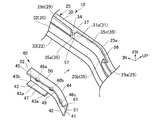
- FIG. 4 is an exploded perspective view of the rear cab mount bracket and the reinforcing member from the front lower side.
- FIG. 5 is a perspective view from the front lower side of the rear cab mount bracket and the reinforcing member.
- FIG. 6 is a front view seen from the VI direction of FIG. 7 is a cross-sectional view taken along arrow VII-VII in FIG.
- FR indicates the front of the vehicle
- UP indicates the upper side
- IN indicates the inner side in the vehicle width direction.
- the left-right direction means the left-right direction with the vehicle facing forward.
- the vehicle member reinforcing structure includes a rear cab mount of a cab-over type truck (vehicle) 1 in which a cab 2 is disposed generally above an engine 3 (see FIG. 2). 6 is applied to the reinforcing structure of the rear cab mount bracket (vehicle member) 10 (see FIG. 2).
- the cab 2 has a front end lower portion supported rotatably around a front cab mount 5 provided at a front end portion of the vehicle body frame 4 and a rear cab mount 6 fixed to the vehicle body frame 4 on a rear end lower portion of the cab 2.
- a normal position where the cab 2 is supported from below (the position of the cab 2 shown in FIG. 1), and a tilt position (not shown) where the rear end lower part of the cab 2 is rotated forward and upward with the front cab mount 5 as a rotation axis. It is possible to move between.
- the vehicle body frame 4 is arranged between a pair of left and right side members 7 disposed on both sides in the vehicle width direction below the track 1 and extending along the front-rear direction, and the left and right side members 7. And a plurality of cross members 8 (only one cross member 8 is shown in FIG. 2) extending in the vehicle width direction and connecting the left and right side members 7 to each other.
- Left and right front wheels 9 that are rotatably supported on the vehicle body frame 4 side via travel axles (not shown) are provided at both ends in the vehicle width direction below the cab 2.
- the engine 3 is mounted on the left and right side members 7 below the cab 2 via an engine mount (not shown).
- the engine 3 includes an air supply duct (not shown), an exhaust duct (not shown), and an EGR for recirculating a part of the exhaust gas from the exhaust duct side to the air supply duct side as EGR (Exhaust Gas Recirculation) gas.
- EGR exhaust Gas Recirculation
- Various on-vehicle components such as the duct 70 are fixed.
- the rear cab mount 6 includes an arch-shaped cab rear member 11 fixed to the left and right side members 7, and a pair of left and right air suspensions fixed to the left and right sides above the cab rear member 11. 12, a floating member 13 extending in the vehicle width direction and elastically supported by the cab rear member 11 via the left and right air suspensions 12, and a pair of left and right strikers 14 fixed to both left and right ends of the floating member 13.
- the left and right strikers 14 are locked by a locking device (not shown) in a pair of left and right cab block brackets 16 fixed to a cab mount rail 15 extending in the vehicle width direction at the lower rear end of the cab 2.
- the cab 2 is held in the normal position.
- the rear cab mount 6 elastically supports the rear end lower portion of the cab 2 at the normal position from below via the left and right air suspensions 12 and the like.
- other elastic support members for example, coil springs may be provided.
- the cab rear member 11 is fixed to the upper end portions of a pair of left and right vertical brackets 17L and 17R which are fixed to the left and right side members 7 at the lower end and rise up along a substantially vertical direction, and the left and right vertical brackets 17L and 17R. And a rear cab mount bracket 10 that connects the upper end portions to each other, and is formed in an arch shape.
- the engine 3 is disposed between the left and right vertical brackets 17L and 17R and below the rear cab mount bracket 10.
- the left and right vertical brackets 17 ⁇ / b> L and 17 ⁇ / b> R are fixed at the lower ends along the vehicle lateral direction outer surfaces of the left and right side members 7, and the upper ends are disposed above the left and right side members 7.
- the rear cab mount bracket 10 has a cross-sectional hat composed of a flat plate-like upper plate portion 18, flat plate-like longitudinal plate portions 19, 20, and plate-like front and rear flange portions 21, 22. It is a metal member formed in a shape and extends in the vehicle width direction above the engine 3 in a long shape.
- the upper plate portion 18 crosses the vertical direction.
- the front and rear vertical plate portions 19 and 20 are bent from the front and rear end edges of the upper plate portion 18 and extend downward to intersect the front-rear direction.
- the front flange portion 21 extends forward from the lower end edge of the front vertical plate portion 19 and intersects the vertical direction
- the rear flange portion 22 extends forward from the lower end edge of the rear vertical plate portion 20. Crosses with the vertical direction.
- the rear cab mount bracket 10 extends substantially horizontally in the vehicle width direction at both ends in the vehicle width direction, and each of the left and right support end portions 23 and 24 and the left and right support end portions 23 and 24.
- Left and right inclined portions 25, 26 extending from the inner end in the vehicle width direction so as to incline upward inward in the vehicle width direction, and extending substantially horizontally in the vehicle width direction at the center portion in the vehicle width direction, 26 and a central connecting portion 27 that connects the inner ends in the vehicle width direction.
- the upper ends of the left and right vertical brackets 17L, 17R are fixed to the lower surfaces of the left and right support ends 23, 24, and the left and right air suspensions 12 are fixed to the upper surfaces of the left and right support ends 23, 24.
- the left and right support ends 23 and 24 of the rear cab mount bracket 10 are supported on the vehicle body frame 4 side (vehicle body side) via the left and right vertical brackets 17L and 17R.
- the front lower portion of the left inclined portion 25 has a notch portion to avoid interference with the EGR duct 70 (see FIG. 2) fixed to the upper left portion of the engine 3 (see FIG. 2). 28 is provided.
- a reinforcing member 40 for reinforcing the notch portion 28 is joined to the rear cab mount bracket 10 by welding.
- the left inclined portion 25 includes an inclined front flange portion 29 that is an area located in the left inclined portion 25 of the front flange portion 21 and the front vertical plate portion 19.
- An inclined front plate portion (plate-like portion) 30 which is a region located in the left inclined portion 25 of the above, and an inclined upper plate portion 31 which is a region located in the left inclined portion 25 of the upper plate portion 18;
- the flange portion 33 is formed.
- Each plate portion 29, 30, 31, 32, 33 of the left inclined portion 25 is from the lower side outside the vehicle width direction to the upper side inside the vehicle width direction (or from the upper side inside the vehicle width direction to the lower side outside the vehicle width direction). It extends along a predetermined direction inclined toward the vehicle width direction.
- a curved portion 25a that is slightly curved downward is provided on one side of the left inclined portion 25 in the predetermined direction with respect to the central portion in the predetermined direction (in this embodiment, on the lower side outside in the vehicle width direction). .
- the inclined portion 25 on the other side in the predetermined direction with respect to the curved portion 25a (in the present embodiment, the upper side on the inner side in the vehicle width direction) extends substantially linearly along the predetermined direction.
- the left inclined portion 25 may not be provided with the curved portion 25a, and may be the left inclined portion 25 that extends substantially linearly along the predetermined direction as a whole.
- the notched portion 28 includes a one-side region 29a on one side in the predetermined direction above the notched portion 28 and a second region 29b on the other side in the predetermined direction from the notched portion 28. And split into The notch 28 cuts the lower edge (one edge along the predetermined direction) 34 of the upper and lower end edges 37 and 34 extending along the predetermined direction of the inclined front plate part 30 into a concave shape. Lack.
- One end of the notch 28 in the predetermined direction is disposed in the vicinity of one end of the left inclined portion 25 in the predetermined direction, and the other end of the notch 28 in the predetermined direction is Further, it is arranged on the other side of the predetermined direction with respect to the bending portion 25a.
- the one side region 29a and the other side region 29b of the front flange portion 29 are separated from each other by the length L1 of the cutout portion 28 along the predetermined direction.
- the inclined front plate portion 30 of the left inclined portion 25 has a notched edge portion 35 that is formed on the lower end edge portion 34 of the inclined front plate portion 30 and divides the notched portion 28. It extends along a predetermined direction.
- the notch edge 35 extends continuously from the edge of the other side region 29b of the front flange portion 29 and extends to the other end edge of the notched portion 28 of the front plate portion 30 in the predetermined direction.
- a portion 35a and a side edge 35b that continuously extends from the edge of the one side region 29a of the front flange portion 29 and defines one side in the predetermined direction of the cutout portion 28 of the front plate portion 30.
- the upper end edge 35c that connects the upper ends of the other end edge 35a and the one end edge 35b.
- the upper end edge 35c of the notch end edge 35 is disposed between the upper and lower end edges 37, 34 extending along the predetermined direction of the inclined front plate part 30, and extends along the predetermined direction.
- One side of the inclined front plate portion 30 in the predetermined direction is supported on the vehicle body frame 4 side via the left support end 23 and the left vertical bracket 17L, and the other side of the inclined front plate portion 30 in the predetermined direction is The vehicle body 4 is supported on the side of the vehicle body frame 4 via the central connecting portion 27, the right support end 24, and the right vertical bracket 17R (see FIG. 2).
- the reinforcing member 40 includes a reinforcing upper plate portion 41 formed in a shape along the lower surface 31a of the inclined upper plate portion 31 of the left inclined portion 25, and a rear portion of the reinforcing upper plate portion 41.
- the reinforcing rear plate portion 43 that is bent from the other side region 42a on the other side in the predetermined direction of the end edge 42 and extends downward, and the reinforcing front plate 41 that is bent from the entire area of the front end edge 44 of the reinforcing upper plate portion 41 and extends downward.
- a plate portion (reinforcing plate) 45 is integrally provided.
- the reinforcing member 40 has a predetermined mounting position in the internal space 36 of the left inclined portion 25 defined by the inclined upper plate portion 31, the inclined rear plate portion 32, and the inclined front plate portion 30 of the left inclined portion 25 (FIG. 5). And is joined to the left inclined portion 25 by welding.
- the reinforcing upper plate portion 41 of the reinforcing member 40 has a plurality of (three in this embodiment) through-holes 46a, 46b, and 46c that are spaced apart from each other along the predetermined direction, and the left inclined portion.
- the one side in the predetermined direction is formed in a state curved downward along the 25 curved portions 25a.
- the length L2 of the reinforcing upper plate portion 41 in the predetermined direction is formed longer than the length L1 of the notch portion 28.
- the upper surface of the reinforcing upper plate portion 41 is in surface contact with the lower surface 31a of the inclined upper plate portion 31 of the left inclined portion 25. With the reinforcing member 40 disposed at the predetermined mounting position, the reinforcing upper plate portion 41 is joined to the lower surface 31a of the inclined upper plate portion 31 by plug welding so as to close the three through holes 46a, 46b, 46c.
- the reinforcing rear plate portion 43 of the reinforcing member 40 extends along the rear end edge 42 of the reinforcing upper plate portion 41 from the other end portion of the reinforcing upper plate portion 41 in the predetermined direction to one side in the predetermined direction.
- the lower end edge 47 along the predetermined direction of the rear reinforcing plate portion 43 is disposed above the lower end edge along the predetermined direction of the inclined rear plate portion 32, and after reinforcement.
- One end of the plate portion 43 in the predetermined direction is disposed in the vicinity of the other side of the bending portion 25a in the predetermined direction.
- the rear surface of the reinforced rear plate portion 43 is in surface contact with the front surface 32a of the inclined rear plate portion 32 of the left inclined portion 25, and the other side of the reinforced rear plate portion 43 on the other side in the predetermined direction.
- the end edge portion overlaps the front surface 32a of the inclined rear plate portion 32 from the front, and the lower end edge portion 47 of the reinforcing rear plate portion 43 overlaps the front surface 32a of the inclined rear plate portion 32 from the front.
- the lower end surface 43a of the reinforced rear plate portion 43 and the front surface 32a of the inclined rear plate portion 32 are welded, and the reinforced rear plate portion 43 in the predetermined direction is welded.
- the other end face 43b and the front surface 32a of the inclined rear plate portion 32 are welded.
- the welding region 48a between the lower end surface 43a of the reinforced rear plate portion 43 and the front surface 32a of the inclined rear plate portion 32 extends from the end portion on one side of the reinforced rear plate portion 43 in the predetermined direction along the lower end surface 43a.
- the lower end surface 43a of the reinforced rear plate portion 43 and the front surface 32a of the inclined rear plate portion 32 are joined in a linear shape.
- a welding region 48b between the end surface 43b on the other side in the predetermined direction of the reinforced rear plate portion 43 and the front surface 32a of the inclined rear plate portion 32 is continuously reinforced from the end portion on the other side in the predetermined direction of the welding region 48a.
- the rear plate portion 43 extends along the other end surface 43b in the predetermined direction, and the end surface 43b and the front surface 32a of the inclined rear plate portion 32 are joined linearly.
- “joining linearly” means joining not by spot welding such as spot welding but by welding continuously along a predetermined direction.
- the reinforcing front plate portion 45 of the reinforcing member 40 is formed in a substantially rectangular shape, bends from the entire area of the front end edge 44 of the reinforcing upper plate portion 41, and extends downward. A part of the other side of the direction faces the rear reinforcing plate portion 43 at a position spaced forward from the rear reinforcing plate portion 43.
- the distance from the reinforcing upper plate portion 41 to the lower end edge portion (one end edge portion in the predetermined direction) 49 of the reinforcing front plate portion 45 is from the reinforcing upper plate portion 41 to the lower end edge portion 47 of the reinforcing rear plate portion 43.
- the distance is set to be approximately the same as the distance.
- the front surface (front surface) 50 of the reinforcing front plate portion 45 is in surface contact with the rear surface (one surface of the plate-like portion) 30a of the inclined front plate portion 30 of the left inclined portion 25 (reinforcing front plate portion).
- a portion of the front surface 50 of 45 that is in surface contact with the rear surface 30a of the inclined front plate portion 30 is also referred to as a first portion).
- the notched edge 35 of the inclined front plate 30 is overlapped with the front surface 50 of the reinforcing front plate 45 from the front, and the reinforcing front plate 45 is notched.
- the upper region (inclined upper plate portion 31 side) of the portion 28 is covered from the rear side (internal space 36 side), and a portion of the front surface 50 of the reinforcing front plate portion 45 is forward from the notch portion 28. It becomes an exposed surface 50a (second portion) exposed to the surface. As shown in FIG.
- both end edges of the reinforcing front plate portion 45 in the predetermined direction are disposed above the lower end edge portion 34 of the inclined front plate portion 30 and cross the cutout portion 28 of the inclined front plate portion 30 along the predetermined direction.
- One end edge portion, the other end edge portion 51 and 52 are disposed on both sides of the notch portion 28 in the predetermined direction and overlap the rear surface 30a of the inclined front plate portion 30 from the rear, and the lower end edge portion of the reinforcing front plate portion 45 49, both end portions (one end portion, the other end portion) 53 and 54 in the predetermined direction overlap the rear surface 30a of the inclined front plate portion 30 from the rear.
- the surface means not the surface opposite to the rear surface but the outer surface of the object.
- the exposed surface 50 a of the reinforcing front plate portion 45 and the notched edge portion 35 of the inclined front plate portion 30 are welded in a state where the reinforcing member 40 is disposed at the predetermined mounting position. Is done.
- a welding region (first welding region) 55 between the exposed surface 50 a of the reinforcing front plate portion 45 and the cut-out edge portion 35 of the inclined front plate portion 30 is formed with a lower end surface 56 of the upper edge portion 35 c of the cut-out edge portion 35.
- the welding region 55a extends in the predetermined direction along the upper edge 35c of the notch edge 35, and the lower end surface 56 of the upper edge 35c of the notch edge 35 and the exposed surface 50a of the reinforcing front plate 45.
- the weld region 55b extends continuously from the other end portion in the predetermined direction of the weld region 55a along the end surface 57 of the other end edge portion 35a of the notch end edge portion 35, and the other side of the notch end edge portion 35.
- the end surface 57 of the end edge portion 35a and the exposed surface 50a of the front reinforcing plate portion 45 are joined in a linear shape.
- the welding region 55c extends from the end of one side in the predetermined direction of the welding region 55a continuously along the end surface of the one end edge 35b of the notch end edge 35, and is one end of the notch end edge 35.
- the end surface on the other side in the predetermined direction of the edge portion 35b and the exposed surface 50a of the reinforcing front plate portion 45 are joined in a linear shape.
- the rear surface 30a of the inclined front plate portion 30 and the one end edge 51 in the predetermined direction of the reinforcing front plate portion 45 are arranged.
- the end surface 61 is welded, and the rear surface 30a of the inclined front plate portion 30 and the end surface 62 of the one end portion 53 in the predetermined direction of the lower end edge portion 49 of the reinforcing front plate portion 45 are welded.
- a welding region (second welding region) 59 between the rear surface 30 a of the inclined front plate portion 30 and the end surface 61 of the one end edge portion 51 of the reinforcing front plate portion 45 is an inclined upper plate of the one end edge portion 51 of the reinforcing front plate portion 45. Extending along the one end edge 51 from a position spaced downward from the lower surface 31a of the part 31 to the lower end of the one end edge 51, the rear surface 30a of the inclined front plate part 30 and the one end edge 51 of the reinforcing front plate part 45 Join linearly.
- the welding region (fourth welding region) 60 between the rear surface 30a of the inclined front plate portion 30 and the end surface 62 of the one end portion 53 of the lower end edge portion 49 of the reinforcing front plate portion 45 is the lower end of the welding region 59 (of the one end edge portion 51).
- the rear surface 30a of the inclined front plate portion 30 and the one end portion 53 of the lower end edge portion 49 of the reinforcing front plate portion 45 are joined linearly.
- the other end of the welding region 60 in the predetermined direction is disposed at a position spaced from one end edge 35b of the notched end edge 35 of the inclined front plate 30 to the one side in the predetermined direction.
- a welding region (fifth welding region) 66 between the rear surface 30a of the inclined front plate portion 30 and the other end portion 54 in the predetermined direction of the lower end edge portion 49 of the reinforcing front plate portion 45 is a lower end (other end edge) of the welding region 65.
- One end portion of the welding region 66 in the predetermined direction is disposed at a position spaced from the other end edge portion 35a of the notched end edge portion 35 of the inclined front plate portion 30 to the other side in the predetermined direction.
- each of the analysis models A and B includes a rear cab mount bracket 10 and a reinforcing member 40, and the analysis model A reinforces the rear surface 30 a of the inclined front plate portion 30 of the rear cab mount bracket 10 and the reinforcing member 40.
- An analysis model (an analysis model to which the reinforcing structure according to the present embodiment is applied) in which one end portion 53 of the lower end edge portion 49 of the front plate portion 45 is joined (having a welding region 60), while an analysis model B is In the analysis model, the rear surface 30a of the inclined front plate portion 30 of the rear cab mount bracket 10 and the one end portion 53 of the lower end edge portion 49 of the reinforcing front plate portion 45 of the reinforcing member 40 are not joined (there is no welding region 60). is there.
- the central connecting portion 27 of each of the analysis models A and B is supported with the support end 23 on the left side of the rear cab mount bracket 10 of the two analysis models A and B being supported.
- the same load in the vehicle width direction is input to the predetermined area 69 on one side in the predetermined direction with respect to the notch portion 28 of the front inclined plate portion 30 of the left inclined portion 25 (see FIG. 7).
- Compare the stresses acting on The predetermined region 69 is located in the vicinity of the corner 67 (see FIG. 7) between the one end edge portion 51 and the lower end edge portion 49 of the reinforcing front plate portion 45 of the reinforcing member 40 in the rear surface 30 a of the inclined front plate portion 30.
- the stress acting on the predetermined region is derived by measuring stresses at a plurality of locations (eight locations in this simulation) in the corner vicinity region 69 of the inclined front plate portion 30 and calculating an average value thereof. .
- the strength of the rear cab mount bracket 10 is higher as the stress acting on the corner vicinity region 69 of the inclined front plate portion 30 is smaller.
- the stress acting on the corner vicinity region 69 of the inclined front plate portion 30 was lower by about 23.4% in the analysis model A than in the analysis model B.
- the upper end edge portion 68 of the reinforcing front plate portion 45 of the reinforcing member 40 contacts the lower surface 31 a of the inclined upper surface portion 31 at the predetermined mounting position.
- the lower end edge portion 49 of the reinforcing front plate portion 45 is disposed above the lower end edge portion 34 of the inclined front plate portion 30 and crosses the notch portion 28 of the inclined front plate portion 30 along the predetermined direction, thereby reinforcing the reinforcement.
- Both end edges (one end edge part, the other end edge part) 51, 52 of the front plate part 45 in the predetermined direction are arranged on both sides of the notch part 28 in the predetermined direction, and are rearward of the rear surface 30a of the inclined front plate part 30.
- the two end portions (one end portion, the other end portion) 53 and 54 in the predetermined direction of the lower end edge portion 49 of the reinforcing front plate portion 45 overlap the rear surface 30a of the inclined front plate portion 30 from the rear. That is, the reinforcing front plate portion 45 of the reinforcing member 40 is joined in a state of being overlapped with a region around the notch portion 28 in the inclined front plate portion 30 of the rear cab mount bracket 10.
- the one end portion 53 of the lower end edge portion 49 of the portion 51 and the reinforcing front plate portion 45 is joined linearly.
- the one end edge portion 51 of the reinforcing front plate portion 45 of the reinforcing member 40 and the reinforcing front plate portion 45 of the reinforcing member 40 with respect to the rear surface 30 a of the inclined front plate portion 30 are described above, on one side of the inclined front plate portion 30 in the predetermined direction, the one end edge portion 51 of the reinforcing front plate portion 45 of the reinforcing member 40 and the reinforcing front plate portion 45 of the reinforcing member 40 with respect to the rear surface 30 a of the inclined front plate portion 30.
- the strength of the corner vicinity region 69 of the inclined front plate portion 30 is improved as compared with the case where the one end portion 53 of the lower end edge portion 49 of the reinforcing front plate portion 45 is not joined. Can be made. Therefore, as can be seen from the simulation results, the other side of the inclined front plate portion 30 of the rear cab mount bracket 10 is substantially flush with the inclined front plate portion 30 and in the predetermined direction. When a force in the direction crossing the vehicle (in this embodiment, the vehicle width direction) is input, it is possible to reduce the stress acting on the corner vicinity region 69 on one side of the predetermined direction of the inclined front plate portion 30. The rear cab mount bracket 10 can be prevented from being damaged.
- the reinforcing member 40 is disposed in the inner space 36 of the left inclined portion 25, and the notched end edge portion 35 of the inclined front plate portion 30 overlaps the front surface 50 of the reinforcing front plate portion 45 from the front, A welding region 55 between the exposed surface 50 a of 45 and the notched end edge portion 35 of the inclined front plate portion 30 is exposed in front of the rear cab mount bracket 10.
- the reinforcing front plate portion 45 is disposed on the front side of the inclined front plate portion 30, and the welding region 55 between the reinforcing front plate portion 45 and the notched end edge portion 35 of the inclined front plate portion 30 is a rear cab mount.
- bracket 10 is provided on the inner space 36 side, during welding, interference between the welding rod and other portions of the rear cab mount bracket 10 (for example, the inclined rear plate portion 32) is avoided. It is possible to perform welding easily by bringing the welding rod into contact with the welding region 55 easily.
- the notch portion 28 is provided in the left inclined portion 25 of the rear cab mount bracket 10 and the reinforcing member 40 is joined to the left inclined portion 25.
- the present invention is not limited to this.
- a cutout portion 28 may be provided in the right inclined portion 26, and the reinforcing member 40 may be joined to the right inclined portion 26.
- the lower end of the welding region 59 (the lower end of the one end edge portion 51) that joins the rear surface 30 a of the inclined front plate portion 30 and the one end edge portion 51 of the reinforcing front plate portion 45, and the inclined front plate portion 30.
- the rear surface 30a and the end portion on one side in the predetermined direction of the welding region 60 that joins the end surface 62 of the one end portion 53 of the lower end edge portion 49 of the reinforcing front plate portion 45 are made continuous, it is limited to this. It is not a thing.
- the lower end of the welding region 59 (the lower end of the one end edge portion 51) and the end portion on the one side in the predetermined direction of the welding region 60 may not be continuous (separated from each other).
- the rear surface 30a of the inclined front plate portion 30 and the both end portions 53 and 54 of the lower end edge portion 49 of the reinforcing front plate portion 45 are joined linearly, but the present invention is not limited to this.
- the rear surface 30 a of the inclined front plate portion 30 on one side in the predetermined direction with respect to the notch portion 28 is joined to the one end portion 53 of the lower end edge portion 49 of the reinforcing front plate portion 45.
- the rear surface 30a of the inclined front plate portion 30 on the other side in the predetermined direction than the notch portion 28 may not be joined to the other end portion 54 of the lower end edge portion 49 of the reinforcing front plate portion 45.
- this indication was demonstrated based on the said embodiment, this indication is not limited to the content of the said embodiment, Of course, it can change suitably in the range which does not deviate from this indication. That is, it is needless to say that other embodiments, examples, operational techniques, and the like made by those skilled in the art based on this embodiment are all included in the scope of the present disclosure.
- the vehicle member reinforcement structure according to the present disclosure is applied to the rear cab mount bracket 10, but may be applied to other vehicle members (for example, the floating member 13 and the like).
- the vehicle member reinforcing structure according to the present disclosure is applied to the vehicle member (rear cab mount bracket 10) having a cross-sectional hat shape, but other cross-sectional shapes (for example, an L-shaped cross-section, You may apply to the member for vehicles of flat form.
- the predetermined direction in which the plate-like portion (the inclined front plate portion 30) extends is from the lower side outside the vehicle width direction to the upper side inside the vehicle width direction (or the upper side inside the vehicle width direction to the outer side in the vehicle width direction.
- the predetermined direction in which the plate-like portion extends is not limited to the above direction.
- the reinforcement structure of the member for vehicles which concerns on this indication has a plate-shaped part (inclined front board part 30) extended along a predetermined direction, and the both sides of the said predetermined direction are supported by the vehicle body side.
- the present invention can be applied to a vehicle member having a plate-like portion in which at least one side in the predetermined direction is supported on the vehicle body side. Even in this case, when a force in a direction substantially intersecting the plate-like portion and crossing the predetermined direction is input to the other side of the plate-like portion in the predetermined direction, The stress acting on one side in the predetermined direction can be reduced, and the vehicle member can be prevented from being damaged.
- the reinforcement structure of the vehicle member which concerns on this indication was applied to the vehicle member which has a plate-shaped part (tilt front board part 30) extended along a predetermined direction and crossing the front-back direction.
- the present invention is applied to a vehicle member having a plate-like portion extending along a predetermined direction and intersecting with the vertical direction, or a vehicle member having a plate-like portion extending along a predetermined direction and intersecting with the vehicle width direction. Also good.
- the present invention has an effect that the strength of the vehicle member in which the interference part with other in-vehicle parts is cut out can be ensured, and is useful for the reinforcement structure of the vehicle member.
Landscapes
- Engineering & Computer Science (AREA)
- Chemical & Material Sciences (AREA)
- Combustion & Propulsion (AREA)
- Transportation (AREA)
- Mechanical Engineering (AREA)
- Body Structure For Vehicles (AREA)
Abstract
リアキャブマウントブラケット10の傾斜前板部30には、切欠部28を補強するための補強部材40の補強前板部45が切欠部28のうちの上側の領域を後側から覆う位置に配置されて接合される。溶接領域55aは、切欠端縁部35の上側端縁部35cと補強前板部45とを線状に接合する。溶接領域59は、補強前板部45の一端縁部51と傾斜前板部30の後面30aとを線状に接合する。溶接領域60は、溶接領域59の下端から連続して傾斜前板部30の後面30aと補強前板部45の下端縁部49の一端部53とを線状に接合する。溶接領域65は、補強前板部45の他端縁部52と傾斜前板部30の後面30aとを線状に接合する。
Description
本開示は、車両用メンバの補強構造に関する。
特許文献1には、サイドフレームに対して左右のロアブラケットを介して取り付けられたリアキャブマウントブラケットが記載されている。このリアキャブマウントブラケットは、断面コ字状のチャンネル材で構成されており、そのウエブ部分が上面を向いており、両側にフランジ部分が形成されている。リアキャブマウントブラケットは、両側部分と、その間に位置しており且つ上方にふくらんでいる中心部分とから構成されている。リアキャブマウントブラケットの両側部分は、いずれも車両の外方向に延びる水平部分を有しており、水平部分の内側には、上方に傾斜している内側部分が形成されている。リアキャブマウントブラケットの中心部分は、中心の水平に延びる中央部分と、その中央部分の両側から下方に傾斜する傾斜端部分とで構成され、その傾斜部分がリアキャブマウントブラケットの内側部分とそれぞれボルト締めされている。リアキャブマウントブラケットの中心部分の下方には、エンジンやエンジンのヘッドカバー等が配置される。
特許文献1に記載の車両では、エンジン及びヘッドカバーの上方にリアキャブマウントブラケット(車両用メンバ)の中心部分が配置されているので、エンジンやヘッドカバーに対して他の車載部品(例えば、EGRダクト等)を固定すると、前記他の車載部品が、リアキャブマウントブラケットのフランジ部分等に干渉してしまうおそれがある。リアキャブマウントブラケットと前記他の車載部品との干渉を回避するために、リアキャブマウントブラケットのフランジ部分のうち前記他の車載部品との干渉部分を切り欠くと、リアキャブマウントブラケットの強度が低下してしまい、リアキャブマウントブラケットの所望の強度を確保できないおそれがある。
そこで、本開示は、他の車載部品との干渉部分を切り欠いた車両用メンバの強度を確保することが可能な車両用メンバの補強構造の提供を目的とする。
上記課題を解決するため、本開示の車両用メンバの補強構造は、車両用メンバと補強板とを備える。車両用メンバは、所定方向に沿って延びる平板状の板状部を有し、板状部の上記所定方向に沿った一端縁部を切り欠く切欠部を区画する切欠端縁部が板状部の上記一端縁部に形成され、上記所定方向の少なくとも一方側で板状部が車体側に支持される。補強板は、切欠部の少なくとも一部を覆う所定の取付位置に配置され、取付位置で板状部に溶接によって接合される。板状部と補強板との間の溶接領域は、第1溶接領域と第2溶接領域と第3溶接領域と第4溶接領域とを含む。補強板が取付位置に配置された状態で、板状部の一面と補強板の表面とが面接触し、補強板の上記所定方向の両端縁部は、板状部の一面に重なり、板状部の切欠端縁部は、補強板の表面に重なり、補強板の上記所定方向に沿った一端縁部は、上記所定方向に沿って切欠部を横断し、補強板の上記一端縁部の両端部は、板状部の一面に重なる。第1溶接領域は、板状部の切欠端縁部と補強板の表面とを線状に接合する。第2溶接領域は、補強板の上記両端縁部のうち上記所定方向の一方側の端縁部と板状部の一面とを線状に接合する。第3溶接領域は、補強板の上記両端縁部のうち上記所定方向の他方側の端縁部と板状部の一面とを線状に接合する。第4溶接領域は、補強板の一端縁部の両端部のうち上記所定方向の一方側の端部と板状部の一面とを線状に接合する。
上記構成では、補強板が取付位置に配置された状態で、板状部の一面と補強板の表面とが面接触し、補強板の上記所定方向の両端縁部は、板状部の一面に重なり、板状部の切欠端縁部は、補強板の表面に重なり、補強板の上記所定方向に沿った一端縁部は、上記所定方向に沿って切欠部を横断し、補強板の上記一端縁部の両端部は、板状部の一面に重なる。すなわち、切欠部の周辺の領域の板状部の一面に補強板が重なるので、車両用メンバに切欠部を設けても、切欠部の周辺の板状部を補強板によって補強することができ、車両用メンバの強度を確保することができる。
また、板状部の上記所定方向の一方側(車体側に支持される側)では、第2溶接領域が、補強板の上記両端縁部のうち上記所定方向の一方側の端縁部と板状部の一面とを線状に接合し、第4溶接領域が、補強板の一端縁部の両端部のうち上記所定方向の一方側の端部と板状部の一面とを線状に接合する。このように、板状部の上記所定方向の一方側では、第2溶接領域及び第4溶接領域で補強板を板状部に接合するので、第2溶接領域のみで補強板を板状部に接合する場合に比べ、上記所定方向の一方側の板状部のうち補強板の角部(補強板の上記所定方向の一方側の端縁部と補強板の一端縁部との角部)の近傍の領域(以下、板状部の角部近傍領域という)の強度を向上させることができる。すなわち、車体側に支持される側(上記所定方向の一方側)の板状部の角部近傍領域の強度を向上させることができるので、例えば、板状部の上記所定方向の他方側に対して、板状部が延びる同一平面上で且つ上記所定方向と交叉する方向の力が入力した際に、車体側に支持される側の板状部の角部近傍領域に作用する応力を低減することができ、車両用メンバの破損を防止することができる。
本開示によれば、他の車載部品との干渉部分を切り欠いた車両用メンバの強度を確保することができる。
以下、本開示の一実施形態を図面に基づいて説明する。なお、各図において、FRは車両の前方を、UPは上方を、INは車幅方向内側をそれぞれ示す。また、以下の説明において、左右方向は車両前方を向いた状態での左右方向を意味する。
図1に示すように、本実施形態に係る車両用メンバの補強構造は、キャブ2が概ねエンジン3(図2参照)の上方に配置されるキャブオーバー型のトラック(車両)1のリアキャブマウント6のリアキャブマウントブラケット(車両用メンバ)10(図2参照)の補強構造に適用される。キャブ2は、その前端下部が車体フレーム4の前端部に設けられたフロントキャブマウント5を回転軸として回転自在に支持され、車体フレーム4に固定されたリアキャブマウント6にキャブ2の後端下部が下方から支持された通常位置(図1に図示されたキャブ2の位置)と、フロントキャブマウント5を回転軸としてキャブ2の後端下部が前上方に回転移動したチルト位置(図示省略)との間を移動可能である。
図1及び図2に示すように、車体フレーム4は、トラック1の下方の車幅方向両側に配置されて前後方向に沿って延びる左右1対のサイドメンバ7と、左右のサイドメンバ7の間で車幅方向に延びて左右のサイドメンバ7同士を相互に連結する複数のクロスメンバ8(図2には、1つのクロスメンバ8のみが図示されている)とを有する。キャブ2の下方の車幅方向両端部には、走行車軸(図示省略)を介して車体フレーム4側に回転自在に支持される左右の前輪9が設けられる。キャブ2の下方の左右のサイドメンバ7の上方には、エンジン3がエンジンマウント(図示省略)を介して搭載される。エンジン3には、給気ダクト(図示省略)や、排気ダクト(図示省略)や、排気ダクト側から給気ダクト側へ排気ガスの一部をEGR(Exhaust Gas Recirculation)ガスとして還流させるためのEGRダクト70などの、様々な車載部品が固定される。
図2に示すように、リアキャブマウント6は、左右のサイドメンバ7に固定されるアーチ状のキャブリアメンバ11と、キャブリアメンバ11の上方の左右両側に固定される左右1対のエアサスペンション12と、車幅方向に延びて左右のエアサスペンション12を介してキャブリアメンバ11に弾性支持されるフローティングメンバ13と、フローティングメンバ13の左右両端部に固定される左右1対のストライカ14とを有する。左右のストライカ14は、キャブ2の後端下部で車幅方向に延びるキャブマウントレール15に固定される左右1対のキャブロックブラケット16内のロック装置(図示省略)に係止されてロック状態となり、キャブ2を通常位置に保持する。リアキャブマウント6は、通常位置のキャブ2の後端下部を、左右のエアサスペンション12等を介して下方から弾性支持する。なお、左右のエアサスペンション12に換えて他の弾性支持部材(例えば、コイルスプリング等)を設けてもよい。
キャブリアメンバ11は、下端部が左右のサイドメンバ7に固定されて略鉛直方向に沿って起立する左右1対の縦ブラケット17L,17Rと、左右の縦ブラケット17L,17Rの上端部に固定されて該上端部同士を連結するリアキャブマウントブラケット10とを有し、アーチ状に形成される。左右の縦ブラケット17L,17Rの間であって、且つリアキャブマウントブラケット10の下方には、エンジン3が配置される。左右の縦ブラケット17L,17Rは、その下端部が左右のサイドメンバ7の車幅方向外側面に沿って固定され、上端部が左右のサイドメンバ7よりも上方に配置される。
図3に示すように、リアキャブマウントブラケット10は、平板状の上板部18と、平板状の前後の縦板部19,20と、平板状の前後のフランジ部21,22とによって断面ハット状に形成された金属製の部材であって、エンジン3の上方で車幅方向に長尺状に延びる。上板部18は、上下方向と交叉する。前後の縦板部19,20は、上板部18の前後の端縁から曲折して下方へそれぞれ延びて前後方向と交叉する。前側のフランジ部21は、前側の縦板部19の下端縁から前方へ延びて上下方向と交叉し、後側のフランジ部22は、後側の縦板部20の下端縁から前方へ延びて上下方向と交叉する。
図2に示すように、リアキャブマウントブラケット10は、車幅方向両端部で車幅方向に略水平に延びて左右の支持端部23,24と、左右の支持端部23,24の各々の車幅方向内端から連続して車幅方向内側の上方へ傾斜して延びる左右の傾斜部25,26と、車幅方向中央部で車幅方向に略水平に延びて左右の傾斜部25,26の車幅方向内端同士を連結する中央連結部27とを有する。左右の支持端部23,24の下面側には、左右の縦ブラケット17L,17Rの上端部が固定され、左右の支持端部23,24の上面側には、左右のエアサスペンション12が固定される。すなわち、リアキャブマウントブラケット10の左右の支持端部23,24は、左右の縦ブラケット17L,17Rを介して車体フレーム4側(車体側)に支持される。
図3に示すように、左側の傾斜部25の前下部には、エンジン3(図2参照)の左上部に固定されたEGRダクト70(図2参照)との干渉を避けるために、切欠部28が設けられる。リアキャブマウントブラケット10には、切欠部28を補強するための補強部材40が溶接によって接合される。
図3~図5に示すように、左側の傾斜部25は、前側のフランジ部21のうちの左側の傾斜部25に位置する領域である傾斜前フランジ部29と、前側の縦板部19のうちの左側の傾斜部25に位置する領域である傾斜前板部(板状部)30と、上板部18のうちの左側の傾斜部25に位置する領域である傾斜上板部31と、後側の縦板部20のうちの左側の傾斜部25に位置する領域である傾斜後板部32と、後側のフランジ部22のうちの左側の傾斜部25に位置する領域である傾斜後フランジ部33とによって形成される。左側の傾斜部25の各板部29,30,31,32,33は、車幅方向外側の下方から車幅方向内側の上方(又は、車幅方向内側の上方から車幅方向外側の下方)へ向かって車幅方向に対して傾斜する所定方向に沿って延びる。左側の傾斜部25のうち上記所定方向の中央部よりも上記所定方向の一方側(本実施形態では、車幅方向外側の下方側)には、僅かに下方へ湾曲する湾曲部25aが設けられる。湾曲部25aよりも上記所定方向の他方側(本実施形態では、車幅方向内側の上方側)の傾斜部25は、上記所定方向に沿って略直線状に延びる。なお、左側の傾斜部25に湾曲部25aを設けなくてもよく、全体的に上記所定方向に沿って略直線状に延びる左側の傾斜部25であってもよい。
切欠部28は、左側の傾斜部25の傾斜前フランジ部29を切欠部28よりも上記所定方向の一方側の一側領域29aと切欠部28よりも上記所定方向の他方側の他側領域29bとに分割する。また、切欠部28は、傾斜前板部30の上記所定方向に沿って延びる上下の端縁部37,34のうちの下端縁部(上記所定方向に沿った一端縁部)34を凹状に切り欠く。切欠部28の上記所定方向の一方側の端部は、左側の傾斜部25の上記所定方向の一方側の端部の近傍に配置され、切欠部28の上記所定方向の他方側の端部は、湾曲部25aよりも上記所定方向の他方側に配置される。傾斜前フランジ部29の一側領域29aと他側領域29bとは、上記所定方向に沿って切欠部28の長さL1分だけ離間している。
図4に示すように、左側の傾斜部25の傾斜前板部30は、傾斜前板部30の下端縁部34に形成されて切欠部28を区画する切欠端縁部35を有し、上記所定方向に沿って延びる。切欠端縁部35は、傾斜前フランジ部29の他側領域29bの端縁部から連続して延びて傾斜前板部30の切欠部28の上記所定方向の他方側を区画する他側端縁部35aと、傾斜前フランジ部29の一側領域29aの端縁部から連続して延びて傾斜前板部30の切欠部28の上記所定方向の一方側を区画する一側端縁部35bと、他側端縁部35aと一側端縁部35bの上端部同士を連結する上側端縁部35cとを有する。切欠端縁部35の上側端縁部35cは、傾斜前板部30の上記所定方向に沿って延びる上下の端縁部37,34の間に配置されて上記所定方向に沿って延びる。傾斜前板部30の上記所定方向の一方側は、左側の支持端部23及び左側の縦ブラケット17Lを介して車体フレーム4側に支持され、傾斜前板部30の上記所定方向の他方側は、中央連結部27、右側の支持端部24、及び右側の縦ブラケット17Rを介して車体フレーム4側に支持される(図2参照)。
図3~図5に示すように、補強部材40は、左側の傾斜部25の傾斜上板部31の下面31aに沿う形状に形成された補強上板部41と、補強上板部41の後端縁42のうち上記所定方向の他方側の他側領域42aから曲折して下方へ延びる補強後板部43と、補強上板部41の前端縁44の全域から曲折して下方へ延びる補強前板部(補強板)45とを一体的に有する。補強部材40は、左側の傾斜部25の傾斜上板部31と傾斜後板部32と傾斜前板部30とによって区画される左側の傾斜部25の内部空間36の所定の取付位置(図5に図示された位置)に配置され、左側の傾斜部25に溶接によって接合される。
補強部材40の補強上板部41は、上記所定方向に沿って互いに離間して配置される複数(本実施形態では、3つ)の貫通孔46a,46b,46cを有し、左側の傾斜部25の湾曲部25aに沿うように、上記所定方向の一方側が下方へ湾曲した状態に形成される。補強上板部41の上記所定方向の長さL2は、切欠部28の長さL1よりも長く形成される。上記所定の取付位置では、補強上板部41の上面が、左側の傾斜部25の傾斜上板部31の下面31aに面接触する。補強部材40が上記所定の取付位置に配置された状態で、補強上板部41は、3つの貫通孔46a,46b,46cを塞ぐように栓溶接によって傾斜上板部31の下面31aに接合される。
補強部材40の補強後板部43は、補強上板部41の上記所定方向の他方側の端部から上記所定方向の一方側へ、補強上板部41の後端縁42に沿って延びる。上記所定の取付位置では、補強後板部43の上記所定方向に沿った下端縁部47が、傾斜後板部32の上記所定方向に沿った下端縁部よりも上方に配置され、且つ補強後板部43の上記所定方向の一方側の端部が、湾曲部25aの上記所定方向の他方側の近傍に配置される。また、上記所定の取付位置では、補強後板部43の後面が、左側の傾斜部25の傾斜後板部32の前面32aに面接触し、補強後板部43の上記所定方向の他方側の端縁部が、傾斜後板部32の前面32aに前方から重なり、補強後板部43の下端縁部47が、傾斜後板部32の前面32aに前方から重なる。
補強部材40が上記所定の取付位置に配置された状態で、補強後板部43の下端面43aと傾斜後板部32の前面32aとが溶接され、且つ補強後板部43の上記所定方向の他方側の端面43bと傾斜後板部32の前面32aとが溶接される。補強後板部43の下端面43aと傾斜後板部32の前面32aとの溶接領域48aは、補強後板部43の上記所定方向の一方側の端部からその下端面43aに沿って上記所定方向の他方側の端部まで延びて、補強後板部43の下端面43aと傾斜後板部32の前面32aとを線状に接合する。補強後板部43の上記所定方向の他方側の端面43bと傾斜後板部32の前面32aとの溶接領域48bは、溶接領域48aの上記所定方向の他方側の端部から連続して、補強後板部43の上記所定方向の他方側の端面43bに沿って延び、該端面43bと傾斜後板部32の前面32aとを線状に接合する。なお、本開示において線状に接合するとは、スポット溶接等のような点状の溶接による接合ではなく、所定の方向に沿って連続した溶接による接合のことである。
図4~図7に示すように、補強部材40の補強前板部45は、略矩形状に形成され、補強上板部41の前端縁44の全域から曲折して下方へ延び、その上記所定方向の他方側の一部が補強後板部43から前方に離間した位置で補強後板部43に対向する。補強上板部41から補強前板部45の下端縁部(上記所定方向に沿った一端縁部)49までの距離は、補強上板部41から補強後板部43の下端縁部47までの距離と略同じ距離に設定される。上記所定の取付位置では、補強前板部45の前面(表面)50が、左側の傾斜部25の傾斜前板部30の後面(板状部の一面)30aと面接触する(補強前板部45の前面50のうち傾斜前板部30の後面30aと面接触する部分を第1部分とも呼ぶ)。また、図6に示すように、上記所定の取付位置では、補強前板部45の前面50に傾斜前板部30の切欠端縁部35が、前方から重なり、補強前板部45が、切欠部28のうちの上側(傾斜上板部31側)の領域を後側(内部空間36側)から覆い、補強前板部45の前面50のうちの一部の領域が、切欠部28から前方へ露出する露出面50a(第2部分)となる。また、図7に示すように、上記所定の取付位置では、補強前板部45の上端縁部68が、傾斜上面部31の下面31aに当接し、補強前板部45の下端縁部49が、傾斜前板部30の下端縁部34よりも上方に配置されて傾斜前板部30の切欠部28を上記所定方向に沿って横断し、補強前板部45の上記所定方向の両端縁部(一端縁部,他端縁部)51,52が、切欠部28の上記所定方向の両側に配置されて傾斜前板部30の後面30aに後方から重なり、補強前板部45の下端縁部49の上記所定方向の両端部(一端部,他端部)53,54が、傾斜前板部30の後面30aに後方から重なる。なお、本開示において表面とは、裏面の反対側の表面という意味ではなく、物の外面の意味で使用している。
図5及び図6に示すように、補強部材40が上記所定の取付位置に配置された状態で、補強前板部45の露出面50aと傾斜前板部30の切欠端縁部35とが溶接される。補強前板部45の露出面50aと傾斜前板部30の切欠端縁部35との溶接領域(第1溶接領域)55は、切欠端縁部35の上側端縁部35cの下端面56と補強前板部45の露出面50aとの溶接領域55aと、切欠端縁部35の他側端縁部35aの上記所定方向の一方側の端面57と補強前板部45の露出面50aとの溶接領域55bと、切欠端縁部35の一側端縁部35bの上記所定方向の他方側の端面(図示省略)と補強前板部45の露出面50aとの溶接領域55cとを有する。溶接領域55aは、切欠端縁部35の上側端縁部35cに沿って上記所定方向に延び、切欠端縁部35の上側端縁部35cの下端面56と補強前板部45の露出面50aとを線状に接合する。溶接領域55bは、溶接領域55aの上記所定方向の他方側の端部から連続して切欠端縁部35の他側端縁部35aの端面57に沿って延び、切欠端縁部35の他側端縁部35aの端面57と補強前板部45の露出面50aとを線状に接合する。溶接領域55cは、溶接領域55aの上記所定方向の一方側の端部から連続して切欠端縁部35の一側端縁部35bの端面に沿って延び、切欠端縁部35の一側端縁部35bの上記所定方向の他方側の端面と補強前板部45の露出面50aとを線状に接合する。
図5及び図7に示すように、補強部材40が上記所定の取付位置に配置された状態で、傾斜前板部30の後面30aと補強前板部45の上記所定方向の一端縁部51の端面61とが溶接され、傾斜前板部30の後面30aと補強前板部45の下端縁部49の上記所定方向の一端部53の端面62とが溶接される。傾斜前板部30の後面30aと補強前板部45の一端縁部51の端面61との溶接領域(第2溶接領域)59は、補強前板部45の一端縁部51のうち傾斜上板部31の下面31aから下方へ離間した位置から一端縁部51の下端まで、一端縁部51に沿って延び、傾斜前板部30の後面30aと補強前板部45の一端縁部51とを線状に接合する。傾斜前板部30の後面30aと補強前板部45の下端縁部49の一端部53の端面62との溶接領域(第4溶接領域)60は、溶接領域59の下端(一端縁部51の下端)から連続して上記所定方向の他方側へ向かって延び、傾斜前板部30の後面30aと補強前板部45の下端縁部49の一端部53とを線状に接合する。溶接領域60の上記所定方向の他方側の端部は、傾斜前板部30の切欠端縁部35の一側端縁部35bから上記所定方向の一方側へ離間した位置に配置される。
図5及び図7に示すように、補強部材40が上記所定の取付位置に配置された状態で、傾斜前板部30の後面30aと補強前板部45の上記所定方向の他端縁部52の端面(図示省略)とが溶接され、傾斜前板部30の後面30aと補強前板部45の下端縁部49の上記所定方向の他端部54の端面64とが溶接される。傾斜前板部30の後面30aと補強前板部45の他端縁部52の端面(図示省略)との溶接領域(第3溶接領域)65は、補強前板部45の他端縁部52のうち傾斜上板部31の下面31aから下方へ離間した位置から他端縁部52の下端まで、他端縁部52に沿って延び、傾斜前板部30の後面30aと補強前板部45の他端縁部52とを線状に接合する。傾斜前板部30の後面30aと補強前板部45の下端縁部49の上記所定方向の他端部54との溶接領域(第5溶接領域)66は、溶接領域65の下端(他端縁部52の下端)から連続して上記所定方向の一方側へ向かって延び、傾斜前板部30の後面30aと補強前板部45の下端縁部49の他端部54とを線状に接合する。溶接領域66の上記所定方向の一方側の端部は、傾斜前板部30の切欠端縁部35の他側端縁部35aから上記所定方向の他方側へ離間した位置に配置される。
次に、2つのリアキャブマウントブラケット10の解析モデルA,Bをコンピュータ上に構成し、解析モデルA,Bを用いてリアキャブマウントブラケット10に作用する応力に関するシミュレーションを行なった結果について説明する。なお、解析モデルA,Bの各々は、リアキャブマウントブラケット10及び補強部材40を備えており、解析モデルAは、リアキャブマウントブラケット10の傾斜前板部30の後面30aと補強部材40の補強前板部45の下端縁部49の一端部53とが接合された(溶接領域60を有する)解析モデル(本実施形態に係る補強構造を適用した解析モデル)であり、一方、解析モデルBは、リアキャブマウントブラケット10の傾斜前板部30の後面30aと補強部材40の補強前板部45の下端縁部49の一端部53とが接合されない(溶接領域60を有さない)解析モデルである。
リアキャブマウントブラケットに作用する応力に関するシミュレーションでは、2つの解析モデルA,Bのリアキャブマウントブラケット10の左側の支持端部23を支持した状態で、解析モデルA,Bのそれぞれの中央連結部27に対して車幅方向に同一の大きさの荷重を入力し、左側の傾斜部25の傾斜前板部30の切欠部28よりも上記所定方向の一方側の所定の領域69(図7参照)に作用する応力を比較する。上記所定の領域69は、傾斜前板部30の後面30aのうち、補強部材40の補強前板部45の一端縁部51と下端縁部49との角部67(図7参照)の近傍の領域69(以下、角部近傍領域69と称する)である。上記所定の領域に作用する応力は、傾斜前板部30の角部近傍領域69のうちの複数個所(本シミュレーションでは、8カ所)の応力を測定し、それらの平均値を算出することによって導き出す。この場合、傾斜前板部30の角部近傍領域69に作用する応力が小さいほどリアキャブマウントブラケット10の強度が高い。その結果、傾斜前板部30の角部近傍領域69に作用する応力は、解析モデルBに対して解析モデルAの方が、約23.4%低いことが確認された。
上記のように構成されたリアキャブマウントブラケット10の補強構造では、上記所定の取付位置で、補強部材40の補強前板部45の上端縁部68が、傾斜上面部31の下面31aに当接し、補強前板部45の下端縁部49が、傾斜前板部30の下端縁部34よりも上方に配置されて傾斜前板部30の切欠部28を上記所定方向に沿って横断し、補強前板部45の上記所定方向の両端縁部(一端縁部,他端縁部)51,52が、切欠部28の上記所定方向の両側に配置されて傾斜前板部30の後面30aに後方から重なり、補強前板部45の下端縁部49の上記所定方向の両端部(一端部,他端部)53,54が、傾斜前板部30の後面30aに後方から重なる。すなわち、補強部材40の補強前板部45が、リアキャブマウントブラケット10の傾斜前板部30のうちの切欠部28の周辺の領域に重なった状態で接合されるので、補強前板部45の分だけ切欠部28の周辺の前記領域の板厚を増大させて傾斜前板部30を補強することができ、リアキャブマウントブラケット10の強度を確保することができる。
また、リアキャブマウントブラケット10の傾斜前板部30の切欠部28よりも上記所定方向の一方側では、傾斜前板部30の後面30aに対し、補強部材40の補強前板部45の一端縁部51及び補強前板部45の下端縁部49の一端部53が線状に接合される。このように、傾斜前板部30の上記所定方向の一方側では、傾斜前板部30の後面30aに対し、補強部材40の補強前板部45の一端縁部51及び補強前板部45の下端縁部49の一端部53が接合されるので、補強前板部45の下端縁部49の一端部53を接合しない場合に比べ、傾斜前板部30の角部近傍領域69の強度を向上させることができる。このため、上記シミュレーションの結果からも判るように、リアキャブマウントブラケット10の傾斜前板部30の上記所定方向の他方側に対して、傾斜前板部30と略同一平面上で且つ上記所定方向と交叉する方向(本実施形態では、車幅方向)の力が入力した際に、傾斜前板部30の上記所定方向の一方側の角部近傍領域69に作用する応力を低減することができ、リアキャブマウントブラケット10の破損を防止することができる。
従って、本実施形態によれば、他の車載部品(EGRダクト70)との干渉部分を切り欠いたリアキャブマウントブラケット10の強度を確保することができる。
また、補強部材40は、左側の傾斜部25の内部空間36に配置され、傾斜前板部30の切欠端縁部35が、補強前板部45の前面50に前方から重なり、補強前板部45の露出面50aと傾斜前板部30の切欠端縁部35との溶接領域55がリアキャブマウントブラケット10の前方に露出している。このため、例えば、傾斜前板部30の前面側に補強前板部45が配置されて、補強前板部45と傾斜前板部30の切欠端縁部35との溶接領域55がリアキャブマウントブラケット10の内部空間36側に設けられている場合とは異なり、溶接する際に、溶接棒とリアキャブマウントブラケット10の他の部分(例えば、傾斜後板部32等)との干渉を回避することができ、溶接棒を容易に溶接領域55に当接させて、容易に溶接を行うことができる。
なお、本実施形態では、リアキャブマウントブラケット10の左側の傾斜部25に切欠部28を設け、左側の傾斜部25に補強部材40を接合したが、これに限定されるものではなく、例えば、右側の傾斜部26に切欠部28を設け、右側の傾斜部26に補強部材40を接合してもよい。
また、本実施形態では、傾斜前板部30の後面30aと補強前板部45の一端縁部51とを接合する溶接領域59の下端(一端縁部51の下端)と、傾斜前板部30の後面30aと補強前板部45の下端縁部49の一端部53の端面62とを接合する溶接領域60の上記所定方向の一方側の端部とを連続させたが、これに限定されるものではない。溶接領域59の下端(一端縁部51の下端)と、溶接領域60の上記所定方向の一方側の端部とを連続させなくても(互いに離間させても)よい。
また、本実施形態では、傾斜前板部30の後面30aと補強前板部45の下端縁部49の両端部53,54とを線状に接合したが、これに限定されるものではない。例えば、本実施形態のように、左側の支持端部23が支持された状態で中央連結部27に車幅方向に入力する荷重に対し、切欠部28よりも上記所定方向の一方側の傾斜前板部30の強度を確保したい場合には、切欠部28よりも上記所定方向の一方側の傾斜前板部30の後面30aと補強前板部45の下端縁部49の一端部53とを接合すればよく、切欠部28よりも上記所定方向の他方側の傾斜前板部30の後面30aと補強前板部45の下端縁部49の他端部54とを接合しなくてもよい。
以上、本開示について、上記実施形態に基づいて説明を行ったが、本開示は上記実施形態の内容に限定されるものではなく、当然に本開示を逸脱しない範囲で適宜変更が可能である。すなわち、この実施形態に基づいて当業者等によりなされる他の実施形態、実施例および運用技術等は全て本開示の範疇に含まれることは勿論である。
例えば、上記実施形態では、本開示に係る車両用メンバの補強構造を、リアキャブマウントブラケット10に適用したが、他の車両用メンバ(例えば、フローティングメンバ13等)に適用してもよい。
また、上記実施形態では、本開示に係る車両用メンバの補強構造を、断面ハット状の車両用メンバ(リアキャブマウントブラケット10)に適用したが、他の断面形状(例えば、断面L字状や平板状)の車両用メンバに適用してもよい。
また、上記実施形態では、板状部(傾斜前板部30)が延びる所定方向を、車幅方向外側の下方から車幅方向内側の上方(又は、車幅方向内側の上方から車幅方向外側の下方)へ向かって車幅方向に対して傾斜する方向としたが、板状部が延びる所定方向は、上記方向に限定されない。
また、上記実施形態では、本開示に係る車両用メンバの補強構造を、所定方向に沿って延びて上記所定方向の両側が車体側に支持される板状部(傾斜前板部30)を有する車両用メンバに適用したが、少なくとも上記所定方向の一方側が車体側に支持される板状部を有する車両用メンバに適用することができる。この場合であっても、板状部の上記所定方向の他方側に対して、板状部と略同一平面上で且つ上記所定方向と交叉する方向の力が入力した際に、板状部の上記所定方向の一方側に作用する応力を低減することができ、車両用メンバの破損を防止することができる。
また、上記実施形態では、本開示に係る車両用メンバの補強構造を、所定方向に沿って延びて前後方向と交叉する板状部(傾斜前板部30)を有する車両用メンバに適用したが、例えば、所定方向に沿って延びて上下方向と交叉する板状部を有する車両用メンバや、所定方向に沿って延びて車幅方向と交叉する板状部を有する車両用メンバに適用してもよい。この場合であっても、板状部の上記所定方向の他方側に対して、板状部と略同一平面上で且つ上記所定方向と交叉する方向の力が入力した際に、板状部の上記所定方向の一方側(車体側に支持される側)に作用する応力を低減することができ、車両用メンバの破損を防止することができる。
本出願は、2016年3月30日付で出願された日本国特許出願(特願2016-068898)に基づくものであり、その内容はここに参照として取り込まれる。
本発明は、他の車載部品との干渉部分を切り欠いた車両用メンバの強度を確保することができるという効果を有し、車両用メンバの補強構造等に有用である。
3:エンジン
4:車体フレーム
6:リアキャブマウント
10:リアキャブマウントブラケット(車両用メンバ)
11:キャブリアメンバ
19:リアキャブマウントブラケットの前側の縦板部
25:左側の傾斜部
28:切欠部
30:傾斜前板部(板状部)
30a:傾斜前板部の後面(板状部の一面)
34:傾斜前板部の下端縁部(板状部の所定方向に沿った一端縁部)
35:切欠端縁部
40:補強部材
45:補強前板部(補強板)
49:補強前板部の下端縁部(補強板の所定方向に沿った一端縁部)
50:補強前板部の前面(補強板の表面)
51:補強前板部の所定方向の一端縁部
52:補強前板部の所定方向の他端縁部
53:補強前板部の下端縁部の所定方向の一端部
54:補強前板部の下端縁部の所定方向の他端部
55:溶接領域(第1溶接領域)
59:溶接領域(第2溶接領域)
60:溶接領域(第4溶接領域)
65:溶接領域(第3溶接領域)
4:車体フレーム
6:リアキャブマウント
10:リアキャブマウントブラケット(車両用メンバ)
11:キャブリアメンバ
19:リアキャブマウントブラケットの前側の縦板部
25:左側の傾斜部
28:切欠部
30:傾斜前板部(板状部)
30a:傾斜前板部の後面(板状部の一面)
34:傾斜前板部の下端縁部(板状部の所定方向に沿った一端縁部)
35:切欠端縁部
40:補強部材
45:補強前板部(補強板)
49:補強前板部の下端縁部(補強板の所定方向に沿った一端縁部)
50:補強前板部の前面(補強板の表面)
51:補強前板部の所定方向の一端縁部
52:補強前板部の所定方向の他端縁部
53:補強前板部の下端縁部の所定方向の一端部
54:補強前板部の下端縁部の所定方向の他端部
55:溶接領域(第1溶接領域)
59:溶接領域(第2溶接領域)
60:溶接領域(第4溶接領域)
65:溶接領域(第3溶接領域)
Claims (4)
- 所定方向に沿って延びる平板状の板状部を有し、前記板状部の前記所定方向に沿った一端縁部を切り欠く切欠部を区画する切欠端縁部が前記板状部の前記一端縁部に形成され、前記所定方向の少なくとも一方側で前記板状部が車体側に支持される車両用メンバと、
前記切欠部の少なくとも一部を覆う所定の取付位置に配置され、前記取付位置で前記板状部に溶接によって接合される補強板と、を備え、
前記板状部と前記補強板との間の溶接領域は、第1溶接領域と第2溶接領域と第3溶接領域と第4溶接領域とを含み、
前記補強板が前記取付位置に配置された状態で、前記板状部の一面と前記補強板の表面とが面接触し、前記補強板の前記所定方向の両端縁部は、前記板状部の前記一面に重なり、前記板状部の前記切欠端縁部は、前記補強板の前記表面に重なり、前記補強板の前記所定方向に沿った一端縁部は、前記所定方向に沿って前記切欠部を横断し、前記補強板の前記一端縁部の両端部は、前記板状部の前記一面に重なり、
前記第1溶接領域は、前記板状部の前記切欠端縁部と前記補強板の前記表面とを線状に接合し、
前記第2溶接領域は、前記補強板の前記両端縁部のうち前記所定方向の前記一方側の端縁部と前記板状部の前記一面とを線状に接合し、
前記第3溶接領域は、前記補強板の前記両端縁部のうち前記所定方向の他方側の端縁部と前記板状部の前記一面とを線状に接合し、
前記第4溶接領域は、前記補強板の前記一端縁部の前記両端部のうち前記所定方向の前記一方側の端部と前記板状部の前記一面とを線状に接合する
ことを特徴とする車両用メンバの補強構造。 - 前記補強板の前記表面は、前記補強板が前記取付位置に配置された状態で、前記板状部の前記一面と面接触する第1部分と、前記板状部から露出する第2部分と、を有する、
ことを特徴とする、請求項1記載の車両用メンバの補強構造。 - 前記第1溶接領域は、前記補強板の前記表面の前記第2部分と前記板状部の前記切欠端縁部とを接合する、
ことを特徴とする、請求項2記載の車両用メンバの補強構造。 - 前記補強板の前記一端縁部のうち、前記両端部以外の部分は前記板状部から露出する、
ことを特徴とする、請求項1記載の車両用メンバの補強構造。
Priority Applications (1)
| Application Number | Priority Date | Filing Date | Title |
|---|---|---|---|
| CN201780018260.3A CN108778906B (zh) | 2016-03-30 | 2017-03-27 | 车辆用构件的加强结构 |
Applications Claiming Priority (2)
| Application Number | Priority Date | Filing Date | Title |
|---|---|---|---|
| JP2016068898A JP6663590B2 (ja) | 2016-03-30 | 2016-03-30 | 車両用メンバの補強構造 |
| JP2016-068898 | 2016-03-30 |
Publications (1)
| Publication Number | Publication Date |
|---|---|
| WO2017170358A1 true WO2017170358A1 (ja) | 2017-10-05 |
Family
ID=59965577
Family Applications (1)
| Application Number | Title | Priority Date | Filing Date |
|---|---|---|---|
| PCT/JP2017/012313 Ceased WO2017170358A1 (ja) | 2016-03-30 | 2017-03-27 | 車両用メンバの補強構造 |
Country Status (3)
| Country | Link |
|---|---|
| JP (1) | JP6663590B2 (ja) |
| CN (1) | CN108778906B (ja) |
| WO (1) | WO2017170358A1 (ja) |
Families Citing this family (2)
| Publication number | Priority date | Publication date | Assignee | Title |
|---|---|---|---|---|
| JP7323469B2 (ja) * | 2020-01-22 | 2023-08-08 | 日野自動車株式会社 | 車両のフレーム構造 |
| JP7219421B2 (ja) * | 2020-02-05 | 2023-02-08 | いすゞ自動車株式会社 | キャブサスペンション支持構造 |
Citations (2)
| Publication number | Priority date | Publication date | Assignee | Title |
|---|---|---|---|---|
| JPS5769771U (ja) * | 1980-10-16 | 1982-04-27 | ||
| JPS63142275U (ja) * | 1987-03-11 | 1988-09-20 |
Family Cites Families (3)
| Publication number | Priority date | Publication date | Assignee | Title |
|---|---|---|---|---|
| JP4539480B2 (ja) * | 2005-08-01 | 2010-09-08 | マツダ株式会社 | 自動車の上部車体構造 |
| DE102011113675A1 (de) * | 2011-09-20 | 2013-03-21 | GM Global Technology Operations LLC (n. d. Gesetzen des Staates Delaware) | Verstärkungsstruktur zum Verstärken einer Seitenwandstruktur für ein Kraftfahrzeug im Bereich eines Türausschnittes |
| CN203186422U (zh) * | 2013-03-20 | 2013-09-11 | 上海同捷科技股份有限公司 | 一种轿车车身纵梁局部加强结构 |
-
2016
- 2016-03-30 JP JP2016068898A patent/JP6663590B2/ja active Active
-
2017
- 2017-03-27 WO PCT/JP2017/012313 patent/WO2017170358A1/ja not_active Ceased
- 2017-03-27 CN CN201780018260.3A patent/CN108778906B/zh active Active
Patent Citations (2)
| Publication number | Priority date | Publication date | Assignee | Title |
|---|---|---|---|---|
| JPS5769771U (ja) * | 1980-10-16 | 1982-04-27 | ||
| JPS63142275U (ja) * | 1987-03-11 | 1988-09-20 |
Also Published As
| Publication number | Publication date |
|---|---|
| CN108778906B (zh) | 2021-04-23 |
| JP2017178067A (ja) | 2017-10-05 |
| CN108778906A (zh) | 2018-11-09 |
| JP6663590B2 (ja) | 2020-03-13 |
Similar Documents
| Publication | Publication Date | Title |
|---|---|---|
| CN103129620B (zh) | 车辆前部的下部车身构造 | |
| CN109664943B (zh) | 纵梁和用于纵梁的制造方法 | |
| JP5075949B2 (ja) | 車体前部構造 | |
| JP6649794B2 (ja) | 車体構造 | |
| JP2008279956A (ja) | 車両用デッキ構造 | |
| JPWO2016129065A1 (ja) | 車体後部構造 | |
| WO2018008467A1 (ja) | キャブの底面部構造 | |
| JP7095430B2 (ja) | 車両の後部車体構造 | |
| WO2017170358A1 (ja) | 車両用メンバの補強構造 | |
| CN110949517B (zh) | 后副车架结构 | |
| JP6907997B2 (ja) | 車両の車体構造 | |
| JP2009202619A (ja) | 車体フレーム補強構造 | |
| JP2022043805A (ja) | 車両 | |
| JP7332061B2 (ja) | 車両のフレーム構造 | |
| JP7158519B2 (ja) | 車体後部構造 | |
| CN108502024B (zh) | 车辆车顶结构 | |
| JP7052653B2 (ja) | 車両後部構造 | |
| JP7750726B2 (ja) | 車両及び車両の製造方法 | |
| JP2016150702A (ja) | 車両の上部車体構造 | |
| JP7501424B2 (ja) | 車両構造 | |
| CN221541721U (zh) | 后纵梁组件及车辆 | |
| JPH0558343A (ja) | 自動車の前部車体構造 | |
| JP3951663B2 (ja) | ブラケット取付構造 | |
| JP2019137170A (ja) | 車両後部構造 | |
| JP2004142683A (ja) | 片側センターピラーレス車両のボディーシェル結合部構造 |
Legal Events
| Date | Code | Title | Description |
|---|---|---|---|
| NENP | Non-entry into the national phase |
Ref country code: DE |
|
| 121 | Ep: the epo has been informed by wipo that ep was designated in this application |
Ref document number: 17774895 Country of ref document: EP Kind code of ref document: A1 |
|
| 122 | Ep: pct application non-entry in european phase |
Ref document number: 17774895 Country of ref document: EP Kind code of ref document: A1 |