WO2017170165A1 - 撮像装置、作動方法、画像処理装置及び画像処理方法 - Google Patents
撮像装置、作動方法、画像処理装置及び画像処理方法 Download PDFInfo
- Publication number
- WO2017170165A1 WO2017170165A1 PCT/JP2017/011820 JP2017011820W WO2017170165A1 WO 2017170165 A1 WO2017170165 A1 WO 2017170165A1 JP 2017011820 W JP2017011820 W JP 2017011820W WO 2017170165 A1 WO2017170165 A1 WO 2017170165A1
- Authority
- WO
- WIPO (PCT)
- Prior art keywords
- reset
- imaging
- unit
- correction
- optical
- Prior art date
- Legal status (The legal status is an assumption and is not a legal conclusion. Google has not performed a legal analysis and makes no representation as to the accuracy of the status listed.)
- Ceased
Links
Images





Classifications
-
- G—PHYSICS
- G03—PHOTOGRAPHY; CINEMATOGRAPHY; ANALOGOUS TECHNIQUES USING WAVES OTHER THAN OPTICAL WAVES; ELECTROGRAPHY; HOLOGRAPHY
- G03B—APPARATUS OR ARRANGEMENTS FOR TAKING PHOTOGRAPHS OR FOR PROJECTING OR VIEWING THEM; APPARATUS OR ARRANGEMENTS EMPLOYING ANALOGOUS TECHNIQUES USING WAVES OTHER THAN OPTICAL WAVES; ACCESSORIES THEREFOR
- G03B5/00—Adjustment of optical system relative to image or object surface other than for focusing
-
- H—ELECTRICITY
- H04—ELECTRIC COMMUNICATION TECHNIQUE
- H04N—PICTORIAL COMMUNICATION, e.g. TELEVISION
- H04N23/00—Cameras or camera modules comprising electronic image sensors; Control thereof
- H04N23/60—Control of cameras or camera modules
- H04N23/68—Control of cameras or camera modules for stable pick-up of the scene, e.g. compensating for camera body vibrations
- H04N23/682—Vibration or motion blur correction
-
- G—PHYSICS
- G02—OPTICS
- G02B—OPTICAL ELEMENTS, SYSTEMS OR APPARATUS
- G02B27/00—Optical systems or apparatus not provided for by any of the groups G02B1/00 - G02B26/00, G02B30/00
- G02B27/0025—Optical systems or apparatus not provided for by any of the groups G02B1/00 - G02B26/00, G02B30/00 for optical correction, e.g. distorsion, aberration
-
- G—PHYSICS
- G02—OPTICS
- G02B—OPTICAL ELEMENTS, SYSTEMS OR APPARATUS
- G02B27/00—Optical systems or apparatus not provided for by any of the groups G02B1/00 - G02B26/00, G02B30/00
- G02B27/64—Imaging systems using optical elements for stabilisation of the lateral and angular position of the image
- G02B27/646—Imaging systems using optical elements for stabilisation of the lateral and angular position of the image compensating for small deviations, e.g. due to vibration or shake
-
- G—PHYSICS
- G06—COMPUTING OR CALCULATING; COUNTING
- G06T—IMAGE DATA PROCESSING OR GENERATION, IN GENERAL
- G06T7/00—Image analysis
- G06T7/70—Determining position or orientation of objects or cameras
-
- H—ELECTRICITY
- H04—ELECTRIC COMMUNICATION TECHNIQUE
- H04N—PICTORIAL COMMUNICATION, e.g. TELEVISION
- H04N23/00—Cameras or camera modules comprising electronic image sensors; Control thereof
- H04N23/50—Constructional details
- H04N23/55—Optical parts specially adapted for electronic image sensors; Mounting thereof
-
- H—ELECTRICITY
- H04—ELECTRIC COMMUNICATION TECHNIQUE
- H04N—PICTORIAL COMMUNICATION, e.g. TELEVISION
- H04N23/00—Cameras or camera modules comprising electronic image sensors; Control thereof
- H04N23/60—Control of cameras or camera modules
-
- H—ELECTRICITY
- H04—ELECTRIC COMMUNICATION TECHNIQUE
- H04N—PICTORIAL COMMUNICATION, e.g. TELEVISION
- H04N23/00—Cameras or camera modules comprising electronic image sensors; Control thereof
- H04N23/60—Control of cameras or camera modules
- H04N23/68—Control of cameras or camera modules for stable pick-up of the scene, e.g. compensating for camera body vibrations
- H04N23/681—Motion detection
- H04N23/6812—Motion detection based on additional sensors, e.g. acceleration sensors
-
- H—ELECTRICITY
- H04—ELECTRIC COMMUNICATION TECHNIQUE
- H04N—PICTORIAL COMMUNICATION, e.g. TELEVISION
- H04N23/00—Cameras or camera modules comprising electronic image sensors; Control thereof
- H04N23/60—Control of cameras or camera modules
- H04N23/68—Control of cameras or camera modules for stable pick-up of the scene, e.g. compensating for camera body vibrations
- H04N23/682—Vibration or motion blur correction
- H04N23/685—Vibration or motion blur correction performed by mechanical compensation
- H04N23/687—Vibration or motion blur correction performed by mechanical compensation by shifting the lens or sensor position
-
- G—PHYSICS
- G03—PHOTOGRAPHY; CINEMATOGRAPHY; ANALOGOUS TECHNIQUES USING WAVES OTHER THAN OPTICAL WAVES; ELECTROGRAPHY; HOLOGRAPHY
- G03B—APPARATUS OR ARRANGEMENTS FOR TAKING PHOTOGRAPHS OR FOR PROJECTING OR VIEWING THEM; APPARATUS OR ARRANGEMENTS EMPLOYING ANALOGOUS TECHNIQUES USING WAVES OTHER THAN OPTICAL WAVES; ACCESSORIES THEREFOR
- G03B2205/00—Adjustment of optical system relative to image or object surface other than for focusing
- G03B2205/0007—Movement of one or more optical elements for control of motion blur
Definitions
- the present invention relates to an image pickup apparatus, an operation method, an image processing apparatus, and an image processing method, and more particularly, an image pickup apparatus, an operation method, an image processing apparatus, and an image processing apparatus that can alleviate shaking in an image caused by a reset operation of an optical correction unit.
- the present invention relates to an image processing method.
- an image pickup apparatus such as a digital camera
- the optical axis of the taking lens is moved relative to the subject due to vibration generated in the image pickup apparatus, and the subject image is shaken in the shot image. So-called camera shake may occur.
- imaging apparatuses having a camera shake correction function have become widespread.
- a camera shake correction function an electronic correction unit that corrects camera shake by performing image processing on captured image data and a camera that integrates at least a part of an imaging optical system or an image sensor, or an imaging optical system and an image sensor
- a camera shake correction unit that combines an electronic correction unit and an optical correction unit has also been proposed.
- Patent Document 1 discloses a high pass when a drive unit limit signal that is a signal indicating that the correction range of the optical correction system is exceeded is detected. It has been disclosed that by making the cut-off frequency of the filter sufficiently low, the amount that cannot be followed by optical correction is supplemented by electronic correction. Further, Patent Document 2 describes that when the optical image shake correction amount reaches the limit, the remaining correction amount obtained by subtracting the limit amount of the optical image shake correction amount from the total image shake correction amount is performed by electronic correction. Yes.
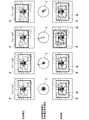
- FIG. 2 shows the movement of the optical correction system during photographing in a state where camera shake correction is being performed, and the change in the angle of view accompanying the movement of the optical correction system.
- frames 1 to 3 are frames in the order of shooting, and represent the flow of moving images.
- the thick frame in each frame is the angle of view F taken in the state where the optical camera shake correction is executed
- the circle L in the center of the figure is the optical correction range of the optical correction system, that is, the correctable range
- the locus in the circle L is The locus of camera shake and the stars in the figure indicate the current position of the optical correction system.
- the angle of view during shooting is fixed with a thick frame. Even in the frame 2, since the position of the optical correction system is within the optical correction range, the angle of view is the same as that in the frame 1. However, in frame 2, since the optical correction system is located at the end of the optical correction range, it is determined that camera shake correction has reached the limit of the optical correction range, and reset operation of the optical correction system is started. That is, the operation of returning the optical correction system to the centering position is started.
- the position of the optical correction system is forced to return to the center, so that the optical correction system moves in a direction unrelated to camera shake.
- the angle of view changes from the frame 2. This change in the angle of view may cause a change in the position of the subject unintended by the user in the moving image, so-called image shake.
- the present invention has been made in view of such circumstances, and provides an imaging apparatus, an operation method, an image processing apparatus, and an image processing method that can alleviate image shaking caused by a reset operation by an optical correction unit. It is intended.
- the imaging apparatus of the present invention includes an imaging optical system having one or more lenses, An imaging unit that has an imaging element and captures a subject image through an imaging optical system to capture a moving image; Camera shake detection means for detecting camera shake; An optical correction unit that optically corrects the camera shake detected by the camera shake detection unit in response to ON by changing the position of the imaging optical system or the image sensor, and stops the correction in response to OFF; Reset judgment means for judging whether or not to reset the position of the imaging optical system or the imaging device, The optical correction means resets the position of the imaging optical system or the imaging element in response to the determination that the reset determination means resets, In response to the start of resetting by the optical correction unit, the electronic correction unit further electronically corrects a change in the position of the subject based on the resetting operation by the optical correction unit in the image captured by the imaging unit. It will be.
- the operating method of the present invention includes an imaging optical system having one or more lenses, An imaging unit having an imaging element and capturing a moving image by capturing a subject image through the imaging optical system; Camera shake detection means for detecting camera shake; Optical correction means for optically correcting camera shake by changing the position of the imaging optical system or imaging device; Reset judging means for judging whether or not to reset the position of the imaging optical system or imaging device; An operation method of an imaging apparatus comprising: an electronic correction unit that electronically corrects a change in the position of a subject in an image captured by an imaging unit, In response to turning on the optical correction means, the camera shake detection means detects camera shake, and optically corrects the camera shake detected by the optical correction means, The reset determining means determines whether or not to reset the position of the imaging optical system or imaging element; In response to the determination of resetting, the optical correction unit stops the correction and starts resetting the position of the imaging optical system or the imaging element, and the electronic correction unit is an optical type in the image captured by the imaging unit. A change in
- “resetting the position of the image pickup optical system or image pickup device” means an operation of returning to the normal centering position, that is, the center position when the optical correction unit is not turned on
- the “change in the position of the subject based on the reset operation by the optical correction unit” means the image shake caused by the reset operation of the optical correction unit.
- the optical correction unit may be turned on, for example, when the camera shake correction mode is turned on by the user, or may be automatically performed when camera shake is detected by the camera shake detection unit.
- the optical correction unit may be turned off, for example, when the camera shake correction mode is turned off by the user, or when the camera shake is not detected by the camera shake detection unit and a certain time has elapsed. May be.
- the electronic correction unit changes the position of the subject in the image based on the reset operation of the position of the imaging optical system or the imaging element during the reset operation by the optical correction unit. Correction to cancel can be performed.
- correction for canceling the change in the position of the subject means that the subject in the image is moved by performing the reset operation of the optical correction means, that is, the operation of returning the position of the imaging optical system or imaging device to the centering position. This means correction for moving the subject in the direction opposite to the direction of movement.
- the electronic correction unit can perform correction to restore the canceled subject position in response to the optical correction unit being turned on again.
- “in response to the optical correction unit being turned on again” means that the optical correction unit is turned on after the optical correction unit is turned off and the reset operation is performed.
- ⁇ Correction that restores the canceled subject position '' means that the subject position is moved in the direction opposite to the direction in which the subject was corrected by the electronic correction means during the reset operation. To do.
- the reset determining means resets in response to the correction of the image pickup optical system or the image pickup element by the correction by the optical correction means.
- the correction limit has been reached means a case where the position of the imaging optical system or the imaging element moved by the optical correction means is located at the end of the correctable range.
- the imaging optical system or the imaging element in response to the reset determination unit being positioned within the end region of the range that can be corrected by the optical correction unit, the imaging optical system or the imaging element is positioned for a predetermined time or more. , Can be determined to reset.
- within the end region of the correctable range means the inside of the preset end side region within the correctable range.
- the reset determination unit resets in response to the start of panning imaging in a state where the optical correction unit is turned on.
- panning shooting means a method of shooting while moving the camera in the horizontal direction or the vertical direction.
- the imaging apparatus of the present invention includes a shake detection means for detecting a shake of the imaging apparatus body, It can be determined that the reset determining means resets in response to the integral value of the value detected by the shake detecting means exceeding a set threshold value.
- the imaging apparatus of the present invention includes a shake detection means for detecting a shake of the imaging apparatus body, It can be determined that the reset determining means resets in response to the state in which the value detected by the shake detecting means is smaller than the set threshold value continuing for a set period of time.
- the operating method of the present invention is an operating method of an imaging apparatus further comprising a shake detection means for detecting a shake of the imaging apparatus body, It can be determined that the reset determination means resets in response to the integral value of the value detected by the shake detection means exceeding a set threshold value.
- the operating method of the present invention is an operating method of an imaging apparatus further comprising a shake detection means for detecting a shake of the imaging apparatus body, It can be determined that the reset determining means resets in response to the state in which the value detected by the shake detecting means is smaller than the set threshold value continuing for a set period of time.
- An image processing apparatus includes an imaging optical system having one or more lenses, an imaging unit that has an imaging element and images a subject image through the imaging optical system, and a camera shake detection unit that detects camera shake. And an optical correction unit that optically corrects the camera shake detected by the camera shake detection unit in response to ON by changing the position of the imaging optical system or image sensor, and stops the correction in response to OFF.
- a reset determination unit that determines whether or not to reset the position of the optical system or the image sensor, and the position of the image pickup optical system or the image sensor in response to the optical correction unit determining that the reset determination unit resets.
- Input means for inputting image data of a moving image taken by an imaging device that resets the image and data indicating the start timing of resetting of the optical correction means; Based on the reset operation by the optical correction means in the image data in response to the fact that the data indicating the reset start timing of the optical correction means in the image data input by the input means indicates the start of reset.
- Electronic correction means for electronically correcting changes in the position of the subject.
- the image processing method of the present invention also includes an image pickup optical system having one or more lenses, an image pickup unit having an image pickup element to pick up a subject image through the image pickup optical system, and a camera shake detection for detecting a camera shake. And an optical correction unit that optically corrects the camera shake detected by the camera shake detection unit in response to ON by changing the position of the imaging optical system or the imaging element, and stops the correction in response to OFF.
- a reset determining unit that determines whether or not to reset the position of the imaging optical system or the imaging element, and in response to the determination by the optical correction unit that the reset determining unit resets, the imaging optical system or the imaging element Input the image data of the moving image taken by the imaging device that resets the position and the data indicating the start timing of resetting the optical correction means, In the input image data, in response to the data indicating the reset start timing of the optical correction unit indicating the start of reset, the position of the subject based on the reset operation by the optical correction unit in the image data Electronically correct for any changes.
- the “data indicating the reset start timing” may be flag data set based on the determination result of the reset determination means, or when the optical correction means starts resetting. It may be flag data that has been set. Further, for example, it may be data obtained from a difference between a motion amount obtained from a gyro sensor and a motion amount obtained from image analysis. For example, when a value indicating that the gyro sensor is rotated 5 degrees to the right is obtained and a value indicating that it is rotated 6 degrees to the right is obtained by image analysis, the image is obtained from the information of the gyro sensor. Since the analysis result is rotated once more, it can be determined that the imaging optical system has moved, that is, the reset has started.
- the camera shake detection unit detects the camera shake, optically corrects the camera shake detected by the optical correction unit, and performs a reset determination.
- the means determines whether or not to reset the position of the imaging optical system or the image sensor, and in response to the determination to reset, the optical correction means stops the correction and resets the position of the imaging optical system or the image sensor
- the electronic correction means electronically corrects the change in the position of the subject based on the reset operation by the optical correction means in the image taken by the photographing means, so that the reset operation by the optical correction means is performed.
- the resulting image shake that is, the change in the position of the subject unintended by the user in the moving image can be alleviated.
- an imaging optical system having one or more lenses, an imaging unit that has an imaging element and images a subject image through the imaging optical system, and a camera shake And an optical device that optically corrects the camera shake detected by the camera shake detecting unit in response to ON by changing the position of the imaging optical system or the image sensor, and stops the correction in response to OFF.
- a reset determining unit that determines whether or not to reset the position of the imaging optical system or the imaging element, and the optical correction unit is responsive to the determination that the reset determining unit resets.
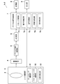
- FIG. 1 is a block diagram of a digital camera 1 according to a first embodiment of the present invention.
- the figure which shows another example of the change of the angle of view accompanying the motion of the optical correction lens during photography in the state where camera shake correction is performed, and the movement of the optical correction lens The flowchart for demonstrating the flow of imaging
- a digital camera will be described as an example of the imaging apparatus of the first embodiment of the present invention.
- the scope of the present invention is not limited to this, and for example, a digital video camera and a camera are included.
- the present invention is also applicable to other electronic devices having an imaging function having an optical correction means, such as a mobile information terminal (PDA; Personal Data Assistant) with a camera such as a mobile phone, a media player, a tablet terminal, and a smartphone.
- PDA mobile information terminal
- a camera such as a mobile phone, a media player, a tablet terminal, and a smartphone.
- FIG. 1 is a block diagram showing the functional configuration of the digital camera 1
- FIG. 2 shows the movement of the optical correction system during shooting and the change in the angle of view accompanying the movement of the optical correction system in a state where camera shake correction is performed.
- frames 1 to 3 are frames in the order of shooting, and represent the flow of moving images.
- the thick frame in each frame is the angle of view F taken in the state where the optical camera shake correction is executed
- the circle L in the center of the figure is the optical correction range of the optical correction system, that is, the correctable range
- the locus in the circle L is The locus of camera shake, the star in the figure, indicates the current position of the optical correction system.
- a dotted frame in the lower part of FIG. 2 indicates a cut-out angle of view G obtained by cutting out an area having the number of pixels set in advance with respect to the angle of view F by an electronic correction unit 72 described later and narrowing it to a certain size.
- the digital camera 1 includes an imaging optical system 2 including one or more photographing lenses, a lens driving unit 3 that drives various lenses of the imaging optical system 2, and the imaging optical system 2.
- An image sensor 4 that receives a subject image that has passed through, an analog signal processor 5 that performs various analog signal processing such as amplifying an output signal from the image sensor 4, and an analog image signal that has been subjected to signal processing by the analog signal processor 5
- An A / D (Analog-to-Digital) converter 6 for converting into digital image data
- a digital signal processor 7 for performing various signal processing on the digital image data converted by the A / D converter 6, and various digital A storage unit 8 that stores information associated with signal processing and an output unit 9 that outputs an image subjected to the digital signal to the storage unit 8 or a display unit (not shown) are provided.
- the imaging optical system 2 is for imaging a subject image on a predetermined imaging plane (the imaging element 4 inside the camera body).
- the imaging optical system 2 includes a focus lens, a zoom lens, and a zoom lens.
- An optical correction lens or the like is provided.
- Each of these lenses is step-driven by a lens driving unit 3 including a zoom lens driving unit 31 including a motor and a motor driver, a focus lens driving unit 32, and an optical correction unit 33.
- the zoom lens driving unit 31 steps drives the zoom lens in the optical axis direction based on operation amount data of an operation unit such as a zoom / up / down arrow button (not shown) provided in the digital camera 1.
- the focus lens driving unit 32 step-drives the focus lens in the optical axis direction based on focus drive amount data output from a signal processing unit 73 having an AF processing unit (not shown).
- the optical correction unit (optical correction means) 33 moves the optical correction lens in a direction perpendicular to the optical axis, and will be described later when camera shake (angle blur and shift blur) occurs in the digital camera 1. Based on the movement amount data calculated by the electronic correction unit 72, the camera shake correction is performed by moving the optical correction lens in a direction to cancel the camera shake. This suppresses the movement of light reaching the image sensor 4 to optically reduce camera shake.
- the optical correction unit 33 performs the camera shake correction when the user operates the operation unit (not shown) provided in the digital camera 1 and the camera shake correction mode is turned on, and the camera shake correction mode is turned off. And stop camera shake correction.
- the optical correction unit 33 responds to a determination result by a reset determination unit 71 described later, that is, in response to a determination that the optical correction lens 33 is reset, that is, a normal centering position when the camera shake correction mode is off, Move to the center position that matches the optical axis.
- the reset operation for moving the optical correction lens to the center position is simply referred to as reset.
- the optical correction unit 33 of the present embodiment moves the optical correction lens in a direction perpendicular to the optical axis
- the present invention is not limited to this, and the imaging device 4 is moved with respect to the optical axis. It may be moved in a vertical direction.
- the camera shake correction mode is turned on / off by the user.
- the present invention is not limited to this, and is automatically turned on when camera shake is detected by a camera shake detection unit 74 described later.
- it may be configured to be automatically turned off when a certain period of time has elapsed since the camera shake is not detected by the camera shake detection unit 74, and can be changed as appropriate.
- the image pickup device 4 is, for example, a CCD (Charge Coupled Device) type image pickup device, and is arranged with the image pickup surface facing the image pickup optical system 2 and picks up an image of the subject through the image pickup optical system 2.
- a plurality of pixels are provided in a predetermined arrangement on the imaging surface, and an image of the subject is captured by photoelectrically converting light incident from the subject for each pixel, and an imaging signal is output.
- the analog signal processing unit 5 includes a correlated double sampling circuit that removes noise from the analog image signal, and an auto gain controller that adjusts the gain of the analog image signal, and the analog output from the image sensor 4 as an image signal. Noise in the image signal is removed, and the analog image signal is amplified.
- the A / D converter 6 converts the analog image signal into digital image data. Hereinafter, this digital image data is simply referred to as image data.
- the image sensor 4, the analog signal processing unit 5, and the A / D conversion unit 6 function as a photographing unit that acquires image data.
- the digital signal processing unit 7 includes a reset determination unit (reset determination unit) 71, an electronic correction unit (electronic correction unit) 72, a signal processing unit 73, and a camera shake detection unit (hand shake detection unit) 74.
- reset determination unit reset determination unit
- electronic correction unit electronic correction unit
- signal processing unit 73 signal processing unit
- camera shake detection unit hand shake detection unit
- the reset determination unit 71 determines whether or not to reset the position of the optical correction lens.
- the position of the optical correction lens moved by the optical correction unit 33 (the position indicated by a star) is within the correctable range of the optical correction lens.
- the optical correction unit 33 starts resetting and moves the optical correction lens to the center position as shown in the right diagram in the middle of FIG.
- the electronic correction unit 72 In response to the start of resetting by the optical correction unit 33, the electronic correction unit 72 electronically corrects a change in the position of the subject based on the reset operation by the optical correction unit 33 in the captured image. As shown in the lower part of FIG. 2, an area with a preset number of pixels is cut out with respect to the angle of view F during shooting to generate a cut-out angle of view G that is narrowed to a certain size. Electronic correction is performed by adjusting the cut-out position of the cut-out angle of view G in at least one of the horizontal direction and the vertical direction in the image based on the change in the position of the subject based on the operation.
- the size of the cut-out angle of view G may be a size set in advance in the digital camera 1 or a size that can be changed by the user.
- the cut angle of view G is 3686 ⁇ 1944 pixels with respect to the angle of view F of 4096 ⁇ 2160 pixels. That is, the cut-out view angle G is set to a value of about 90% in the vertical and horizontal directions with respect to the view angle F.
- the center of the cut-out view angle G coincides with the center of the view angle F.
- the image data represented by the cut-out angle of view G is output to the output unit 9 and displayed, for example, on a display unit (not shown).
- the reset determination unit 71 determines that the correction limit has been reached and resets the optical correction lens.
- the optical correction lens is forced to return to the center, so that the optical correction lens moves in a direction unrelated to camera shake.
- the angle of view F changes from the position of the angle of view F of the frame 2. Due to the change in the angle of view F, there may be a change in the position of the subject unintended by the user in the moving image, so-called image shake.
- the amount of change in the angle of view F is calculated from the return amount of the optical correction lens moved toward the center by the reset operation, and the direction in which the angle of view F has changed by the calculated amount of change
- the electronic correction unit 72 performs electronic correction by adjusting the cut-out position of the cut-out angle of view G in a direction that cancels the change amount that is the opposite direction, that is, a direction that cancels the change in the position of the subject in the image.
- the electronic correction amount by the electronic correction unit 72 is obtained by converting the return amount of the optical correction lens into the number of pixels on the image in advance and storing it in the storage unit 8 and based on the detected return amount of the correction lens. This is determined by reading the number of pixels.
- the return amount of the optical correction lens is calculated from the value output from the camera shake detection unit 74 to the optical correction unit 33.
- the electronic correction amount is a value calculated from the difference between the value output from the camera shake detection unit 74 to the optical correction unit 33 and the motion amount of the subject obtained by image analysis, or the motion amount of the subject obtained by image analysis.
- a value processed by adding gain processing or the like may be used.
- the cutting position of the cutting angle of view G is adjusted in the direction of the arrow in the drawing as shown in the lower part of FIG. Therefore, since the cut-out angle of view G can be located at the same position as that of the frame 2 in the frame 3, the image shake due to the reset operation by the optical correction unit 33, that is, the position of the subject unintended by the user in the moving image. Can be mitigated.
- the optical correction is immediately resumed by the optical correction unit 33 while the position after the position adjustment, that is, the cut-out angle of view G is fixed at the position after the electronic correction.
- the optical correction is restarted while the position of the cut-out view angle G is fixed.
- the current reset operation is performed at the next reset operation. Even if an attempt is made to adjust the cutout position in the same direction as shown in FIG. 2, there is no area for adjusting the position of the cutout view angle G in the view angle F as shown in the lower part of FIG. I can't.
- FIG. 3 shows another example of the movement of the optical correction lens during photographing and the change in the angle of view accompanying the movement of the optical correction lens in a state where camera shake correction is being performed. 3 are the same as the frames 1 to 3 in FIG. 2, and thus detailed description thereof will be omitted, and only the frame 4 will be described.
- the optical correction unit 33 does not immediately restart the optical correction.
- the electronic correction unit 72 performs camera shake correction for correcting the camera shake for a predetermined time, and the optical correction unit 33 performs optical correction at the timing when the center of the cut-out view angle G reaches the vicinity of the center of the view angle F. Switch to.
- the timing when the center of the view angle G reaches the vicinity of the center of the view angle F is the timing when the center of the view angle G is located in a predetermined region including the center of the view angle F. Can do.
- the area can be appropriately changed depending on the performance of the digital camera 1 and the like.
- the center of the cut-out angle of view G is positioned near the center of the angle of view F as shown in the lower frame of FIG. Therefore, the correction shown in the frames 1 to 4 can be repeated by returning to the frame 1.
- the signal processing unit 73 performs an image quality correction processing circuit that performs signal processing such as gradation correction processing and gamma correction processing on the input image data, and a still image for image data that has undergone processing such as image quality correction. It sometimes functions as a compression / decompression processing circuit that compresses / decompresses in a predetermined format such as JPEG (Joint / Photographic / Experts / Group) and MPEG (Moving / Photographic / Experts / Group). Also, the focus position is detected based on the image data to determine the focus setting value (focus drive amount), the AF processing unit that outputs the focus drive amount data, and the subject brightness (photometric value) is measured based on the image data.
- JPEG Joint / Photographic / Experts / Group
- MPEG Motion / Photographic / Experts / Group
- exposure setting values such as an aperture value, shutter speed, and exposure time are determined, and an AE processing unit that performs AE processing for outputting aperture value data and shutter speed data, and automatic white balance during imaging It also functions as an AWB processing unit that performs AWB processing to be adjusted.
- the camera shake detection unit 74 detects the vibration of the digital camera 1 main body caused by the user's camera shake, and can be composed of a gyro sensor, an acceleration sensor, or the like. Then, the detected vibration is converted into an electric signal and output to the optical correction unit 33 as an amount of camera shake.
- the storage unit 8 stores various information used in the digital signal processing unit 7 and various digital signal processed images as necessary, and a volatile memory such as a DRAM (Dynamic Random Access Memory) and a flash.
- a volatile memory such as a DRAM (Dynamic Random Access Memory) and a flash.
- a non-volatile memory such as a memory is included.
- the storage unit 8 is provided separately from the digital signal processing unit 7, but the present invention is not limited to this, and the storage unit 8 is provided in the digital signal processing unit 7. Also good.
- the output unit 9 outputs an image subjected to various digital signal processing to the storage unit 8, a display unit (not shown), or a storage unit outside the apparatus by wireless or wired communication.
- each part of the main body is controlled by a CPU (not shown) in accordance with an operation by the operation part and a signal from each functional block.
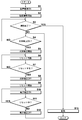
- FIG. 4 shows a flowchart for explaining the flow of shooting by the digital camera 1.
- step S1 when the power of the digital camera 1 is turned on (step S1), the digital camera 1 starts shooting a moving image (step S2).
- step S3 determines whether or not shooting has ended (step S3). For example, if shooting has been ended by a user operation, it is determined that shooting has ended (step S3; YES), and the digital camera 1 1 stores the captured moving image in the storage unit 8 (step S13), and ends a series of shooting processes.
- step S4 it is determined whether or not camera shake correction is turned on, that is, whether or not optical correction by the optical correction unit 33 is turned on (step S4). If the optical correction is not turned on (step S4; NO), the process proceeds to step S3, and the subsequent processes are repeated. If the optical correction is on (step S4; YES), the optical correction by the optical correction unit 33 is started (step S5).
- step S5 When optical correction by the optical correction unit 33 is started (step S5), the reset determination unit 71 starts determining whether or not to reset (step S6), and when it is determined not to reset (step S6). S7; NO), the process proceeds to step S6, and the subsequent processes are repeated. If it is determined to reset (step S7; YES), the optical correction by the optical correction unit 33 is turned off (step S8), and the optical correction lens 33 starts the reset operation of the optical correction lens (step S9). ).
- step S10 the electronic correction unit 72 turns on the electronic correction and executes the electronic correction described above.
- step S11 the reset determination by the reset determination unit 71 is continuously performed to determine whether or not the reset is being performed.
- step S11; YES the process proceeds to step S10, and the electronic correction unit 72 continues the electronic correction.
- step S12 the electronic correction unit 72 ends the electronic correction (step S12), shifts the process to step S4, and performs the subsequent processes. Repeat.
- the processes in steps S8 to S10 are performed in the above order.
- the present invention is not limited to this, and when it is determined in step S7 that resetting is performed (step S7; YES), the electronic correction unit 72 first turns on the electronic correction and executes the electronic correction described above (step S10), and then turns off the optical correction by the optical correction unit 33 (step S8).
- the optical correction unit 33 may start the reset operation of the optical correction lens (step S9).
- step S13 the shot moving image is stored in the storage unit 8 (step S13), and the series of shooting processes ends.
- the optical correction unit 33 stops the correction and starts the reset, and Since the electronic correction unit 72 electronically corrects the change in the position of the subject based on the reset operation in the image, the image shake caused by the reset operation by the optical correction unit 33, that is, the subject unintended by the user in the moving image The change in the position of can be mitigated.
- the reset determination by the reset determination unit 71 is performed when the position of the optical correction lens moved by the optical correction unit 33 is positioned at the end of the optical correction range that is the correctable range of the optical correction lens.
- the reset is determined, but the present invention is not limited to this.
- FIG. 5 is a diagram for explaining the correction range of the optical correction lens.
- an end region M composed of a constant region from the periphery to the center is set within the optical correction range L, that is, within the correctable range, and the optical correction lens is preliminarily set in the end region M.
- the position is set for a predetermined time or longer, there is a possibility that sufficient correction cannot be performed near the end of the optical correction range L. Therefore, it may be determined that the reset is reached because the correction limit is reached.
- the end region M can be configured to be changeable by the user.
- FIG. 6 is a diagram for explaining optical correction at the time of panning shooting
- FIG. 7 is a diagram showing an example of the reset operation of the optical correction system at panning shooting and an example of a change in angle of view
- FIG. It is a figure which shows the relationship between the reset operation
- Panning shooting is one of the techniques for shooting movies.
- Panning shooting refers to a method of shooting while moving the direction of the digital camera 1 in the left-right direction or the up-down direction, and includes shooting such as panning shot while shooting the subject.
- the digital camera 1 when panning shooting is performed, the digital camera 1 is shot while intentionally moving, so depending on the magnitude and speed of vibration detected by the camera shake detection unit 74, that is, the amount of camera shake, for example,
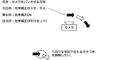
- the shake width is a size that cannot be corrected even when the optical correction lens is moved to the end of the optical correction range, as shown in FIG. 6, optical correction is turned on (black in FIG. 6). If the optical correction is turned off (white arrow in FIG. 6), the optical correction state changes.
- the control for resetting the position of the optical correction lens is performed at the timing when the optical correction is turned off as in the above-described embodiment, when the reset operation of the optical correction lens is started, the position of the optical correction lens is changed. Because the optical correction lens is forced to return to the center, it moves in a direction that is not related to camera shake, and the optical correction changes from the on state to the off state. In some cases, so-called image shaking may occur.
- the reset determination unit 71 determines whether panning shooting is started in a state where the optical correction by the optical correction unit 33 is turned on, and resets when panning shooting is started. to decide. Whether or not panning shooting has been started is determined by, for example, turning on / off the panning shooting mode by a user operating an operation unit (not shown) provided in the digital camera 1, and making a determination based on the on / off signal. . Note that the determination of whether panning shooting has been started is not limited to this, and the position of the optical correction lens moved by the optical correction unit 33 is corrected by the optical correction lens, as in the above-described embodiment.
- the optical correction range which is a possible range
- the optical correction lens is positioned within a set fixed time within the end area of the range that can be corrected by the optical correction unit 33, it is determined that panning shooting for shooting while moving the digital camera 1 is started.
- the integral value of the value detected by the camera shake detection unit 74 exceeds a set threshold value, it may be determined that panning shooting for shooting while moving the digital camera 1 is started.
- the movement amount between the frame 2 and the frame 3, that is, the current movement amount is determined.
- the angle of view fluctuates by an amount that combines the return amount of the optical correction lens upon reset. Since the optical correction is also turned off in the frame 4 similarly to the frame 3, the movement amount in the frame 3, that is, the previous movement amount, the movement amount between the frame 3 and the frame 4, that is, the current movement amount, and the reset.
- the angle of view fluctuates by an amount that combines the return amount of the optical correction lens.
- the reset determination unit 71 determines that the reset is to be performed, that is, when the optical correction is turned off and the reset operation is started, correction by the electronic correction unit 72 is started. Then, as shown in frames 3 and 4, the view angle, that is, the cut-out view angle (displayed view angle) is moved in a direction in which the return amount of the optical correction lens is canceled.
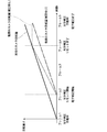
- the digital camera 1 The rotation amount ⁇ of the graph does not change in the inclination of the graph even after the time point of the frame 4. Therefore, even if the reset of the optical correction lens is started in the middle of panning shooting, a moving image in which panning shooting is smoothly performed can be shot.
- FIG. 9 shows a flowchart for explaining the flow of shooting by the digital camera 1.
- FIG. 9 is a flowchart in which processing for canceling electronic correction by the electronic correction unit 72 is added after the reset determination by the reset determination unit 71 in step S11 in the processing of steps S1 to S13 of FIG. A description of the steps performed will be omitted, and only different steps will be described in detail.
- step S30 While the electronic correction is performed by the electronic correction unit 72 (after step S30), the reset determination by the reset determination unit 71 is continuously performed to determine whether the reset is being performed. If it is determined that the reset is not being performed, that is, the reset is completed (step S31; NO), the electronic correction unit 72 cancels the electronic correction (step S32). That is, as described above, as shown in the frame 5 in FIG. 8, the cut angle of view is moved in the direction opposite to the direction moved in the frames 3 and 4, that is, the cut angle of view (the angle of view to be displayed). By moving the center back to the center of the full angle of view (the center of the image), a process for returning to the initial state shown in the frame 1 is performed.
- the electronic correction unit 72 ends the electronic correction (step S33), shifts the processing to step S24, and repeats the subsequent processing. Also in the present embodiment, in the middle of a series of processing, when shooting is ended by a user operation, for example, when the user turns off a shooting mode provided in the digital camera 1, the digital camera 1 Discriminates that the photographing has been completed, shifts the processing to step S34, stores the photographed moving image in the storage unit 8 (step S34), and terminates the series of photographing processing.
- the optical correction unit 33 stops the correction and starts the reset, and After the electronic correction unit 72 electronically corrects or cancels the change in the position of the subject based on the reset operation in the image, the electronic correction unit 72 returns the original position of the canceled subject in response to the optical correction unit 33 being turned on again. Therefore, the frame can be returned to the initial state before the electronic correction, and the electronic correction can be repeatedly performed. As a result, even if the reset of the optical correction lens is started during panning shooting, a moving image in which panning shooting is performed smoothly can be shot.
- FIG. 10 is a block diagram of the digital camera 1-2.
- FIG. 10 is obtained by adding a shake detection unit 75 to the digital signal processing unit 7 of the digital camera 1 of the above-described embodiment shown in FIG. Explained.
- the shake detection unit 75 detects vibration of the digital camera 1-2 main body, and can be configured by a gyro sensor, an acceleration sensor, or the like. The detected vibration is converted into an electrical signal and output to the reset determination unit 71. Note that the gyro sensor, the acceleration sensor, and the like that constitute the shake detection unit 75 can also be used as the gyro sensor, the acceleration sensor, and the like of the shake detection unit 74 described above.
- the reset determination unit 71 determines that the reset is performed in response to the integral value of the value detected and output by the shake detection unit 75 exceeding the set threshold value. That is, when the magnitude of the vibration of the digital camera 1-2 detected by the shake detection unit 75 is larger than a set value, the reset operation is performed in preparation for the next vibration without correcting the vibration. Like that.
- the integration is started when the optical correction unit 33 is turned on, and the value is reset at the timing when the reset is started.
- the reset determination unit 71 determines to reset in response to the state in which the value detected and output by the shake detection unit 75 is smaller than the set threshold value for a set period of time. May be. That is, when it is determined that the digital camera 1-2 is stationary, a reset operation is performed in preparation for the next vibration.
- the position of the optical correction lens by the reset determination unit 71 is reset, as in the digital camera 1 of the above embodiment.
- the optical correction unit 33 stops the correction and starts the reset, and the electronic correction unit 72 electronically corrects the change in the position of the subject based on the reset operation in the image. Further, it is possible to mitigate image fluctuations caused by the reset operation by the optical correction unit 33, that is, changes in the position of the subject unintended by the user in the moving image.
- the optical correction unit 33 stops the correction and starts the reset, and the electronic correction unit 72 resets the image in the image.
- the electronic correction unit 72 resets the image in the image.
- correction for returning the canceled subject position is performed. It is possible to return to the initial state before performing the expression correction, and it is possible to repeatedly perform the electronic correction. As a result, even if the reset of the optical correction lens is started during panning shooting, a moving image in which panning shooting is performed smoothly can be shot.
- the electronic correction unit 72 in FIGS. 1 and 10 can function as an image processing apparatus different from the digital cameras 1 and 1-2. That is, by inputting the image data captured by the digital cameras 1 and 1-2 without the electronic correction unit 72 and the data indicating the reset start timing of the optical correction unit 33 to the image processing apparatus, In response to the fact that the data indicating the reset start timing of the optical correction unit 33 indicates the start of reset, the image processing apparatus detects the position of the subject based on the reset operation by the optical correction unit 33 in the image data. Since the change in the image can be corrected electronically, the image shake caused by the reset operation by the optical correction unit 33, that is, the moving image can be obtained when the image data is reproduced or recorded later, not during real-time shooting. A change in the position of the subject that is not intended by the user can be mitigated.
- the “data indicating the reset start timing” may be flag data set based on the determination result of the reset determination unit 71, or the optical correction unit 33 starts resetting. It may be the flag data set at the time. Further, for example, it may be data obtained from a difference between a motion amount obtained from a gyro sensor and a motion amount obtained from image analysis. For example, when a value indicating that the gyro sensor is rotated 5 degrees to the right is obtained and a value indicating that it is rotated 6 degrees to the right is obtained by image analysis, the image is obtained from the information of the gyro sensor. Since the analysis result is rotated once more, it can be determined that the optical correction lens has moved, that is, resetting has started.
- the imaging apparatus of the present invention is not limited to the above embodiment, and can be changed as appropriate without departing from the spirit of the invention.
Landscapes
- Engineering & Computer Science (AREA)
- Physics & Mathematics (AREA)
- Multimedia (AREA)
- Signal Processing (AREA)
- General Physics & Mathematics (AREA)
- Optics & Photonics (AREA)
- Computer Vision & Pattern Recognition (AREA)
- Theoretical Computer Science (AREA)
- Studio Devices (AREA)
- Adjustment Of Camera Lenses (AREA)
Abstract
【課題】撮像装置において、光学式補正手段によるリセット動作に起因する画像の揺れを緩和する。【解決手段】撮像装置が、撮像光学系と、撮像素子を有し被写体像を撮像して動画像を撮影する撮影手段と、手振れを検出する手振れ検出手段と、検出された手振れを前記撮像光学系又は前記撮像素子の位置を変化させて光学的に補正する光学式補正手段と、前記撮像光学系又は前記撮像素子の位置をリセットするか否かを判断するリセット判断手段とを備え、前記光学式補正手段が前記リセット判断手段のリセットするとの判断に応答して前記撮像光学系又は前記撮像素子の位置をリセットするものであり、リセットの開始に応答して、前記撮影手段により撮影された画像中の前記光学式補正手段によるリセットの動作に基づく被写体の位置の変化を電子的に補正する電子式補正手段を備える。
Description
本発明は、撮像装置、作動方法、画像処理装置及び画像処理方法に関し、特に光学式補正手段のリセット動作に起因する画像中の揺れを緩和することができる撮像装置、作動方法、画像処理装置及び画像処理方法に関するものである。
従来、デジタルカメラなどの撮像装置において、手持ちで撮影をする際等に、撮像装置に生じた振動により撮影レンズの光軸が被写体に対して相対的に移動し、撮影した画像に被写体像の揺れ、いわゆる手振れが生じることがある。このような手振れを補正するために、手振れ補正機能を有する撮像装置が普及している。手振れ補正機能としては、撮影した画像のデータを画像処理して手振れを補正する電子式補正手段と、撮像光学系の少なくとも一部あるいはイメージセンサ、又は撮像光学系とイメージセンサとを一体化したカメラモジュール全体などを移動させて手振れを補正する光学式補正手段とがあり、近年では、電子式補正手段と光学式補正手段とを組み合わせた手振れ補正手段も提案されている。
電子式補正手段と光学式補正手段とを組み合わせた手振れ補正手段としては、特許文献1に、光学補正系の補正可能範囲を超えたことを示す信号である駆動手段リミット信号を検出したときにハイパスフィルタのカットオフ周波数を十分低くすることにより、光学式補正で追従しきれなかった分を電子式補正によって補充することが開示されている。また特許文献2に、光学像振れ補正量が限界になったときには、総合像振れ補正量から光学像振れ補正量の限界量を引いた残りの補正量を電子式補正によって行うことが記載されている。
一方、光学式補正手段においては、光学補正系の位置が光学補正範囲の限界に達した場合に、光学補正系の位置をセンタリング位置に戻す、いわゆるリセット動作を行うものがある。ここで図2に、手振れ補正が実行されている状態での撮影中の光学補正系の動きと光学補正系の動きに伴う画角の変化を示す。なお図2において、フレーム1~3はそれぞれ撮影された順番のフレームであり、動画の流れが表されている。各フレーム中の太枠は光学式手振れ補正が実行されている状態での撮影した画角F、図の中央の円Lは光学補正系の光学補正範囲すなわち補正可能範囲、円L内の軌跡は手振れの軌跡、図中の星は光学補正系の現在の位置をそれぞれ示している。
図2に示すように、フレーム1では、光学補正系の位置が光学補正範囲内に収まっているので、撮影中の画角は太枠で固定される。フレーム2でも、光学補正系の位置は光学補正範囲内に収まっているため、画角はフレーム1と同じとなる。しかしながら、フレーム2では、光学補正系が光学補正範囲の端に位置しているので、手振れ補正は光学補正範囲の限界に達したと判断して、光学補正系のリセット動作を開始する。すなわち光学補正系をセンタリング位置に戻す動作が開始される。
光学補正系のリセット動作が開始されると、光学補正系の位置を強制的に中央に戻そうとするため、光学補正系は手振れとは関係のない方向に動くことになり、フレーム3に示されるように、画角がフレーム2から変化してしまう。この画角の変化により、動画にユーザが意図しない被写体の位置の変化いわゆる画像の揺れが生じてしまう場合がある。
本発明はかかる事情に鑑みてなされたものであり、光学式補正手段によるリセット動作に起因する画像の揺れを緩和することができる撮像装置、作動方法、画像処理装置及び画像処理方法を提供することを目的とするものである。
本発明の撮像装置は、1以上のレンズを有する撮像光学系と、
撮像素子を有し撮像光学系を通して被写体像を撮像して動画像を撮影する撮影手段と、
手振れを検出する手振れ検出手段と、
オンに応答して手振れ検出手段により検出された手振れを撮像光学系又は撮像素子の位置を変化させて光学的に補正し、オフに応答して補正を停止する光学式補正手段と、
撮像光学系又は撮像素子の位置をリセットするか否かを判断するリセット判断手段とを備え、
光学式補正手段が、リセット判断手段のリセットするとの判断に応答して撮像光学系又は撮像素子の位置をリセットするものであり、
光学式補正手段によるリセットの開始に応答して、撮影手段により撮影された画像中の光学式補正手段によるリセットの動作に基づく被写体の位置の変化を電子的に補正する電子式補正手段をさらに備えてなるものである。
撮像素子を有し撮像光学系を通して被写体像を撮像して動画像を撮影する撮影手段と、
手振れを検出する手振れ検出手段と、
オンに応答して手振れ検出手段により検出された手振れを撮像光学系又は撮像素子の位置を変化させて光学的に補正し、オフに応答して補正を停止する光学式補正手段と、
撮像光学系又は撮像素子の位置をリセットするか否かを判断するリセット判断手段とを備え、
光学式補正手段が、リセット判断手段のリセットするとの判断に応答して撮像光学系又は撮像素子の位置をリセットするものであり、
光学式補正手段によるリセットの開始に応答して、撮影手段により撮影された画像中の光学式補正手段によるリセットの動作に基づく被写体の位置の変化を電子的に補正する電子式補正手段をさらに備えてなるものである。
また本発明の作動方法は、1以上のレンズを有する撮像光学系と、
撮像素子を有し前記撮像光学系を通して被写体像を撮像して動画像を撮影する撮影手段と、
手振れを検出する手振れ検出手段と、
手振れを撮像光学系又は撮像素子の位置を変化させて光学的に補正する光学式補正手段と、
撮像光学系又は撮像素子の位置をリセットするか否かを判断するリセット判断手段と、
撮影手段により撮影された画像中の被写体の位置の変化を電子的に補正する電子式補正手段とを備えてなる撮像装置の作動方法であって、
光学式補正手段のオンに応答して、手振れ検出手段が手振れを検出して、光学式補正手段が検出した手振れを光学的に補正し、
リセット判断手段が、撮像光学系又は撮像素子の位置をリセットするか否かを判断し、
リセットするとの判断に応答して、光学式補正手段が補正を停止して撮像光学系又は撮像素子の位置のリセットを開始し、かつ電子式補正手段が撮影手段により撮影された画像中の光学式補正手段によるリセットの動作に基づく被写体の位置の変化を電子的に補正する。
撮像素子を有し前記撮像光学系を通して被写体像を撮像して動画像を撮影する撮影手段と、
手振れを検出する手振れ検出手段と、
手振れを撮像光学系又は撮像素子の位置を変化させて光学的に補正する光学式補正手段と、
撮像光学系又は撮像素子の位置をリセットするか否かを判断するリセット判断手段と、
撮影手段により撮影された画像中の被写体の位置の変化を電子的に補正する電子式補正手段とを備えてなる撮像装置の作動方法であって、
光学式補正手段のオンに応答して、手振れ検出手段が手振れを検出して、光学式補正手段が検出した手振れを光学的に補正し、
リセット判断手段が、撮像光学系又は撮像素子の位置をリセットするか否かを判断し、
リセットするとの判断に応答して、光学式補正手段が補正を停止して撮像光学系又は撮像素子の位置のリセットを開始し、かつ電子式補正手段が撮影手段により撮影された画像中の光学式補正手段によるリセットの動作に基づく被写体の位置の変化を電子的に補正する。
ここで本発明において、「撮像光学系又は撮像素子の位置をリセットする」が、光学式補正手段がオンされていない場合の通常時のセンタリング位置すなわち中央位置に戻す動作を意味し、「画像中の光学式補正手段によるリセットの動作に基づく被写体の位置の変化」は、光学式補正手段のリセット動作に起因する画像の揺れを意味する。また光学式補正手段のオンは、例えばユーザによって手振れ補正モードがオンにされたときに行われても良いし、手振れ検出手段によって手振れが検出されたときに自動的に行われても良い。また光学式補正手段のオフは、例えばユーザによって手振れ補正モードがオフにされたときに行われても良いし、手振れ検出手段によって手振れが検出されなくなって一定の時間が経過したとき等に行われても良い。
本発明の撮像装置及び作動方法は、電子式補正手段が、光学式補正手段によるリセットの動作中に、撮像光学系又は撮像素子の位置のリセットの動作に基づく画像中の被写体の位置の変化をキャンセルする補正を行うことができる。
なお本発明において「被写体の位置の変化をキャンセルする補正」は、光学式補正手段のリセット動作すなわち撮像光学系又は撮像素子の位置をセンタリング位置に戻す動作が行われることによって画像中の被写体が移動した分だけ、この移動の方向とは逆の方向に被写体を移動させる補正を意味する。
また本発明の撮像装置及び作動方法は、電子式補正手段が、光学式補正手段の再度のオンに応答して、キャンセルした被写体の位置を元に戻す補正を行うことができる。
なお本発明において、「光学式補正手段の再度のオンに応答して」は、光学式補正手段がオフされてリセット動作が行われた後に光学式補正手段がオンされた場合を意味し、「キャンセルした被写体の位置を元に戻す補正」は、リセット動作中に電子式補正手段によって補正された画像中の被写体の補正量だけ移動させた向きと逆向きに被写体の位置を移動させることを意味する。
本発明の撮像装置及び作動方法は、リセット判断手段が、光学式補正手段による補正により撮像光学系又は撮像素子が補正限界に達したことに応答して、リセットすると判断することができる。
ここで「補正限界に達した」は、光学式補正手段により移動される撮像光学系又は撮像素子の位置が補正可能範囲の端に位置した場合を意味する。
本発明の撮像装置及び作動方法は、リセット判断手段が、光学式補正手段による補正可能範囲の端部領域内に、撮像光学系又は撮像素子が設定された一定時間以上位置したことに応答して、リセットすると判断することができる。
ここで「補正可能範囲の端部領域内」は、補正可能範囲内の予め設定された端部側の領域内を意味する。
本発明の撮像装置及び作動方法は、リセット判断手段が、光学式補正手段がオンされた状態でのパニング撮影の開始に応答して、リセットすると判断することができる。
なお本発明において「パニング撮影」は、カメラの向きを左右方向又は上下方向に動かしながら撮影する手法を意味する。
また本発明の撮像装置は、撮像装置本体の揺れを検出する揺れ検出手段を備え、
リセット判断手段が、揺れ検出手段により検出された値の積分値が、設定された閾値を超えたことに応答して、リセットすると判断することができる。
リセット判断手段が、揺れ検出手段により検出された値の積分値が、設定された閾値を超えたことに応答して、リセットすると判断することができる。
また本発明の撮像装置は、撮像装置本体の揺れを検出する揺れ検出手段を備え、
リセット判断手段が、揺れ検出手段により検出される値が設定された閾値よりも小さい値である状態が、設定された一定時間継続したことに応答して、リセットすると判断することができる。
リセット判断手段が、揺れ検出手段により検出される値が設定された閾値よりも小さい値である状態が、設定された一定時間継続したことに応答して、リセットすると判断することができる。
また本発明の作動方法は、撮像装置本体の揺れを検出する揺れ検出手段をさらに備えてなる撮像装置の作動方法であって、
リセット判断手段が、揺れ検出手段により検出される値の積分値が、設定された閾値を超えたことに応答して、リセットすると判断することができる。
リセット判断手段が、揺れ検出手段により検出される値の積分値が、設定された閾値を超えたことに応答して、リセットすると判断することができる。
また本発明の作動方法は、撮像装置本体の揺れを検出する揺れ検出手段をさらに備えてなる撮像装置の作動方法であって、
リセット判断手段が、揺れ検出手段により検出される値が設定された閾値よりも小さい値である状態が、設定された一定時間継続したことに応答して、リセットすると判断することができる。
リセット判断手段が、揺れ検出手段により検出される値が設定された閾値よりも小さい値である状態が、設定された一定時間継続したことに応答して、リセットすると判断することができる。
本発明の画像処理装置は、1以上のレンズを有する撮像光学系と、撮像素子を有し撮像光学系を通して被写体像を撮像して動画像を撮影する撮影手段と、手振れを検出する手振れ検出手段と、オンに応答して手振れ検出手段により検出された手振れを撮像光学系又は撮像素子の位置を変化させて光学的に補正し、オフに応答して補正を停止する光学式補正手段と、撮像光学系又は撮像素子の位置をリセットするか否かを判断するリセット判断手段とを備え、光学式補正手段が、リセット判断手段がリセットすると判断したことに応答して撮像光学系又は撮像素子の位置をリセットする撮像装置で撮影された動画像の画像データ及び光学式補正手段のリセットの開始のタイミングを示すデータを入力する入力手段と、
入力手段により入力された画像データにおいて、光学式補正手段のリセットの開始のタイミングを示すデータがリセットの開始を示したことに応答して、画像データ中の光学式補正手段によるリセットの動作に基づく被写体の位置の変化を電子的に補正する電子式補正手段とを備えてなるものである。
入力手段により入力された画像データにおいて、光学式補正手段のリセットの開始のタイミングを示すデータがリセットの開始を示したことに応答して、画像データ中の光学式補正手段によるリセットの動作に基づく被写体の位置の変化を電子的に補正する電子式補正手段とを備えてなるものである。
また本発明の画像処理方法は、1以上のレンズを有する撮像光学系と、撮像素子を有し撮像光学系を通して被写体像を撮像して動画像を撮影する撮影手段と、手振れを検出する手振れ検出手段と、オンに応答して手振れ検出手段により検出された手振れを撮像光学系又は撮像素子の位置を変化させて光学的に補正し、オフに応答して補正を停止する光学式補正手段と、撮像光学系又は撮像素子の位置をリセットするか否かを判断するリセット判断手段とを備え、光学式補正手段が、リセット判断手段がリセットすると判断したことに応答して撮像光学系又は撮像素子の位置をリセットする撮像装置で撮影された動画像の画像データ及び光学式補正手段のリセットの開始のタイミングを示すデータを入力し、
入力された画像データにおいて、光学式補正手段のリセットの開始のタイミングを示すデータがリセットの開始を示したことに応答して、画像データ中の光学式補正手段によるリセットの動作に基づく被写体の位置の変化を電子的に補正する。
入力された画像データにおいて、光学式補正手段のリセットの開始のタイミングを示すデータがリセットの開始を示したことに応答して、画像データ中の光学式補正手段によるリセットの動作に基づく被写体の位置の変化を電子的に補正する。
なお本発明において、「リセットの開始のタイミングを示すデータ」はリセット判断手段の判断結果に基づいてたてられたフラグのデータであってもよいし、光学式補正手段がリセットを開始したときにたてられたフラグのデータであってもよい。また例えばジャイロセンサから得た動き量と画像解析から得た動き量の差分から求められたデータであってもよい。例えば、ジャイロセンサにより右に5度回転していることを示す値が得られ、画像解析により右に6度回転していることを示す値が得られた場合には、ジャイロセンサの情報より画像解析の結果の方が1度余計に回転していることから撮像光学系が動いた、つまりリセットが開始したと判断することができる。
本発明の撮像装置及び作動方法によれば、光学式補正手段のオンに応答して、手振れ検出手段が手振れを検出して、光学式補正手段が検出した手振れを光学的に補正し、リセット判断手段が、撮像光学系又は撮像素子の位置をリセットするか否かを判断し、リセットするとの判断に応答して、光学式補正手段が補正を停止して撮像光学系又は撮像素子の位置のリセットを開始し、かつ電子式補正手段が撮影手段により撮影された画像中の光学式補正手段によるリセットの動作に基づく被写体の位置の変化を電子的に補正するので、光学式補正手段によるリセット動作に起因する画像の揺れ、すなわち動画おけるユーザが意図しない被写体の位置の変化を緩和することができる。
本発明の画像処理装置及び画像処理方法によれば、1以上のレンズを有する撮像光学系と、撮像素子を有し撮像光学系を通して被写体像を撮像して動画像を撮影する撮影手段と、手振れを検出する手振れ検出手段と、オンに応答して手振れ検出手段により検出された手振れを撮像光学系又は撮像素子の位置を変化させて光学的に補正し、オフに応答して補正を停止する光学式補正手段と、撮像光学系又は撮像素子の位置をリセットするか否かを判断するリセット判断手段とを備え、光学式補正手段が、リセット判断手段がリセットすると判断したことに応答して撮像光学系又は撮像素子の位置をリセットする撮像装置で撮影された動画像の画像データ及び光学式補正手段のリセットの開始のタイミングを示すデータとが入力されると、入力された画像データにおいて、光学式補正手段のリセットの開始のタイミングを示すデータがリセットの開始を示したことに応答して、画像データ中の光学式補正手段によるリセットの動作に基づく被写体の位置の変化を電子的に補正するので、リアルタイムでの撮影時ではなく、後で画像データを再生や記録するときに光学式補正手段によるリセット動作に起因する画像の揺れ、すなわち動画おけるユーザが意図しない被写体の位置の変化を緩和することができる。
以下、図面を参照して本発明の実施の形態を説明する。なお、以下の実施の形態では、本発明における第1の実施形態の撮像装置としてデジタルカメラを例に説明するが、本発明の適用範囲はこれに限定されず、例えば、デジタルビデオカメラ、カメラ付き携帯電話、メディアプレーヤ、タブレット端末及びスマートフォン等のカメラ付き携帯情報端末(PDA;Personal Data Assistant)等、光学式補正手段を有する撮像機能を備えた他の電子機器に対しても適用可能である。
ここで図1にデジタルカメラ1の機能構成を示すブロック図、図2に手振れ補正が実行されている状態で撮影中の光学補正系の動きと光学補正系の動きに伴う画角の変化を示す。なお図2において、フレーム1~3はそれぞれ撮影された順番のフレームであり、動画の流れが表されている。各フレーム中の太枠は光学式手振れ補正が実行されている状態での撮影した画角F、図の中央の円Lは光学補正系の光学補正範囲すなわち補正可能範囲、円L内の軌跡は手振れの軌跡、図中の星は光学補正系の現在の位置を示している。また図2の下段の点線枠は後述する電子式補正部72により画角Fに対して予め設定された画素数の領域を切り出して一定のサイズに狭めた切出画角Gを示す。
本実施形態のデジタルカメラ1は、図1に示す如く、1以上の撮影レンズを備えた撮像光学系2と、撮像光学系2の各種レンズを駆動するレンズ駆動部3と、撮像光学系2を通った被写体像を受光する撮像素子4と、撮像素子4からの出力信号を増幅する等各種アナログ信号処理を行うアナログ信号処理部5と、アナログ信号処理部5で信号処理されたアナログ画像信号をデジタル画像データに変換するA/D(Analog to Digital)変換部6と、A/D変換部6で変換されたデジタル画像データに対して各種信号処理を行うデジタル信号処理部7と、各種のデジタル信号処理に伴う情報を記憶する記憶部8と、デジタル信号が施された画像を記憶部8や図示しない表示部に出力する出力部9とを備えている。
撮像光学系2は被写体像を所定の結像面上(カメラ本体内部にある撮像素子4)に結像させるためのものであり、撮像光学系2を構成するものとして、フォーカスレンズ、ズームレンズ及び光学補正レンズ等が設けられている。これらの各レンズは、モータとモータドライバからなるズームレンズ駆動部31、フォーカスレンズ駆動部32及び光学式補正部33からなるレンズ駆動部3によってステップ駆動される。ズームレンズ駆動部31は、デジタルカメラ1に設けられた図示しないズーム/上下矢印ボタン等の操作部の操作量データに基づいてズームレンズを光軸方向にステップ駆動する。フォーカスレンズ駆動部32は、AF処理部(図示しない)を有する信号処理部73から出力されるフォーカス駆動量データに基づいてフォーカスレンズを光軸方向にステップ駆動する。
光学式補正部(光学式補正手段)33は、光学補正レンズを光軸に対して垂直な方向に移動させるものであり、デジタルカメラ1に手振れ(角度ブレ及びシフトブレ)が発生したときに、後述する電子式補正部72によって算出された移動量データに基づいて手振れを打ち消す向きに光学補正レンズを移動することにより手振れ補正を行う。これにより撮像素子4に到達する光の動きを抑えることで、光学的に手振れを軽減させる。
なお本実施形態の光学式補正部33は、デジタルカメラ1に設けられた図示しない操作部をユーザが操作することによって手振れ補正モードがオンされると手振れ補正を行い、手振れ補正モードがオフされると手振れ補正を停止する。また光学式補正部33は、後述するリセット判断部71による判断結果に応答して、すなわちリセットするとの判断に応答して、光学補正レンズを手振れ補正モードがオフの場合の通常時のセンタリング位置つまり光軸と一致する中央位置に移動させる。以降、光学補正レンズを中央位置に移動させるリセット動作を単にリセットという。
本実施形態の光学式補正部33は光学補正レンズを光軸に対して垂直な方向に移動させるものとしたが、本発明はこれに限られるものではなく、撮像素子4を光軸に対して垂直な方向に移動させるものであってもよい。また本実施形態においては、ユーザによって手振れ補正モードがオンオフされる構成としたが、本発明はこれに限られるものではなく、後述する手振れ検出部74によって手振れが検出されたときに自動的にオンし、手振れ検出部74によって手振れが検出されなくなって一定の時間が経過したときに自動的にオフされる構成としてもよいし、適宜変更することができる。
撮像素子4は、例えばCCD(Charge Coupled Device)型撮像素子であり、撮像光学系2に撮像面を向けて配置され、撮像光学系2を通して被写体を撮像する。撮像面には、複数の画素が所定の配列で設けられており、画素毎に被写体から入射した光を光電変換することにより、被写体の像を撮像して、撮像信号を出力する。
アナログ信号処理部5は、アナログ画像信号のノイズ除去を行う相関2重サンプリング回路と、アナログ画像信号のゲイン調整を行うオートゲインコントローラとを有しており、撮像素子4が撮像信号として出力するアナログ画像信号におけるノイズを除去し、アナログ画像信号を増幅する。また、A/D変換部6は、アナログ画像信号をデジタル画像データに変換する。なおこのデジタル画像データを以降、単に画像データという。本実施形態においては撮像素子4、アナログ信号処理部5及びA/D変換部6が、画像データを取得する撮影手段として機能する。
デジタル信号処理部7は、リセット判断部(リセット判断手段)71、電子式補正部(電子式補正手段)72、信号処理部73及び手振れ検出部(手振れ検出手段)74を備えている。
リセット判断部71は、光学補正レンズの位置をリセットするか否かを判断するものである。本実施形態においては、図2の中段の中央図に示すように、光学式補正部33により移動される光学補正レンズの位置(星で示された位置)が、光学補正レンズの補正可能範囲である光学補正範囲の端に位置した場合に、中央からこの端へ向かう方向への補正ができなくなるために補正限界に達したとしてリセットすると判断する。リセット判断部71によりリセットすると判断されると、光学式補正部33がリセットを開始して、図2の中段の右図に示すように、光学補正レンズを中央位置に移動させる。
電子式補正部72は、光学式補正部33によるリセットの開始に応答して、撮影された画像中の光学式補正部33によるリセットの動作に基づく被写体の位置の変化を電子式に補正するものであり、図2の下段に示すように、撮影中の画角Fに対して予め設定された画素数の領域を切り出して一定のサイズに狭めた切出画角Gを生成し、上記リセットの動作に基づく被写体の位置の変化に基づいて、画像における水平方向及び垂直方向の少なくとも一方の方向に切出画角Gの切出位置を調整することにより電子補正を行う。なお切出画角Gのサイズは、予めデジタルカメラ1に設定されたサイズであってもよいし、ユーザによって設定変更可能にされたサイズであってもよい。また本実施形態においては4096×2160ピクセルの画角Fに対して3686×1944ピクセルの切出画角Gとする。すなわち切出画角Gは、画角Fに対して縦、横それぞれ約90%の値とする。
例えば図2に示すように、デジタルカメラ1によって静止している被写体を撮影中に、光学式補正部33により手振れ補正が行われている状態においては、図2に示すように、フレーム1では光学式補正部33により補正される手振れが、光学補正範囲に収まっているため、切出画角Gの中心は画角Fの中心と一致する。なお本実施形態においては、この切出画角Gで表される画像データが出力部9に出力され、例えば図示しない表示部に表示される。
次に、フレーム2でも手振れは光学補正範囲に収まっているため、画角F及び切出画角Gはフレーム1と同じ位置に位置する。しかしながら、フレーム2では、光学補正レンズが光学補正範囲の端に位置しているので、上述したリセット判断部71により補正限界に達したとしてリセットすると判断されて、光学補正レンズのリセット動作が開始される。光学補正レンズのリセット動作が開始されると、光学補正レンズの位置を強制的に中央に戻そうとするため、光学補正レンズは手振れとは関係のない方向に動くことになり、フレーム3に示されるように、画角Fがフレーム2の画角Fの位置から変化してしまう。この画角Fの変化により、動画にユーザが意図しない被写体の位置の変化いわゆる画像の揺れが生じてしまう場合がある。
そこで本実施形態においては、リセット動作により、光学補正レンズが中央に向けて移動した戻り量から画角Fの変化量を算出し、算出した変化量の分だけ、画角Fが変化した方向とは反対の方向である変化量を打ち消す方向、すなわち画像中の被写体の位置の変化をキャンセルする方向に、切出画角Gの切出位置を調整することにより電子式補正部72が電子補正を行う。なお電子式補正部72による電子補正量は、予め光学補正レンズの戻り量を画像上の画素数に換算して、記憶部8に記憶しておき、検出された補正レンズの戻り量に基づいて上記画素数を読み出すことにより決定する。光学補正レンズの戻り量は、手振れ検出部74が光学式補正部33に出力した値から算出されるものとする。また電子補正量は、手振れ検出部74が光学式補正部33に出力した値と画像解析によって得られた被写体の動き量の差分から算出した値や、画像解析で得られた被写体の動き量にゲイン処理等を加えて加工した値等を使用してもよい。
上記のようにして、電子式補正部72が電子補正を行うことにより、図2の下段、右図に示すように、切出画角Gは図中矢印の方向に切出位置が調整されるので、フレーム3においても切出画角Gをフレーム2と同じ位置に位置させることができるので、光学式補正部33によるリセット動作に起因する画像の揺れ、すなわち動画おけるユーザが意図しない被写体の位置の変化を緩和することができる。
なお、電子式補正部72により上記の電子補正が行われた後は、すなわち図2のフレーム3において光学補正レンズが中央に戻った後は、切出画角Gはフレーム3に示される切出位置が調整された後の位置つまり切出画角Gは電子式補正後の位置に固定したままで、すぐに光学式補正部33により光学式補正が再開される。なお本実施形態においては、切出画角Gの位置を固定したままで光学式補正を再開するものとしたが、切出画角Gの位置を固定してしまうと、次回のリセット動作時に今回と同じ方向に切出位置を調整しようとしても、図2の下段、右図に示すように、画角Fにおいて切出画角Gの位置を調整する領域がないため、電子式補正を行うことができない。
そこで電子式補正部72による他の補正方法について以下に説明する。ここで図3に手振れ補正が実行されている状態で撮影中の光学補正レンズの動きと光学補正レンズの動きに伴う画角の変化を示す他の例を示す。なお図3のフレーム1~3は、図2のフレーム1~3と同じ状態を示しているため、ここでの詳細な説明は省略し、フレーム4についてのみ説明する。
本実施形態においては、図3の下段のフレーム3に示すように、画角Fにおいて切出画角Gの位置を調整する領域がないことにより電子式補正を行えなくなることを防ぐために、電子式補正部72により上記の電子補正が行われた後は、すなわち図2のフレーム3において光学補正レンズが中央に戻った後、すぐに光学式補正部33により光学式補正を再開するのではなく、予め定められた一定時間、電子式補正部72により手振れを補正する手振れ補正を行い、切出画角Gの中心が画角Fの中心付近に達したタイミングで光学式補正部33による光学式補正に切替えを行う。なお切出画角Gの中心が画角Fの中心付近に達したタイミングとは、画角Fの中心を含む予め定められた領域内に切出画角Gの中心が位置したタイミングとすることができる。上記領域は、デジタルカメラ1の性能等により適宜変更可能とすることができる。
上記のようにして電子式補正から光学式補正への切替えを行うことにより、図3の下段、フレーム4に示すように、切出画角Gの中心を画角Fの中心付近に位置させることができるので、フレーム1に戻って、フレーム1~4に示す補正を繰り返し行うことができる。
信号処理部73は、入力された画像データに階調補正処理やガンマ補正処理等の信号処理を施す画質補正処理回路や、画質補正等の処理が行われた画像データに対して、静止画像のときにはJPEG(Joint Photographic Experts Group)、動画像のときにはMPEG(Moving Photographic Experts Group)等の所定形式で圧縮/伸張する圧縮伸張処理回路として機能する。また画像データに基づいて焦点位置を検出して合焦設定値(フォーカス駆動量)を決定し、フォーカス駆動量データを出力するAF処理部、画像データに基づいて被写体輝度(測光値)を測定し、測定した被写体輝度に基づいて絞り値、シャッタスピード及び露光時間等の露出設定値を決定し、絞り値データ及びシャッタスピードデータを出力するAE処理を行うAE処理部及び撮像時のホワイトバランスを自動調整するAWB処理を行うAWB処理部としても機能する。
手振れ検出部74は、ユーザの手振れによって生じたデジタルカメラ1本体の振動を検出するものであり、ジャイロセンサや加速度センサ等で構成することができる。そして検出した振動を電気信号に変換し、手振れ量として光学式補正部33へ出力する。
記憶部8は、デジタル信号処理部7に使用される各種の情報、各種デジタル信号処理が施された画像などを必要に応じて記憶する、DRAM(Dynamic Random Access Memory)などの揮発性メモリとフラッシュメモリなどの不揮発性メモリを含んで構成される。なお本実施形態においては、デジタル信号処理部7とは別に記憶部8を設けているが、本発明はこれに限られるものではなく、デジタル信号処理部7に、記憶部8を設けるようにしてもよい。
出力部9は、無線又は有線通信によって、各種のデジタル信号処理が施された画像を記憶部8や不図示の表示部や装置外部の記憶部に出力する。
なおデジタルカメラ1は図示しないCPUにより、操作部による操作や各機能ブロックからの信号に応じて、本体各部が制御される。
以上のように構成されたデジタルカメラ1の作動方法について、図面を参照して詳細に説明する。ここで図4にデジタルカメラ1の撮影の流れを説明するためのフローチャートを示す。
まず、デジタルカメラ1の電源がオンされると(ステップS1)、デジタルカメラ1は動画の撮影を開始する(ステップS2)。デジタルカメラ1は、撮影が終了したか否かを判別し(ステップS3)、例えばユーザの操作により撮影が終了された場合には撮影が終了されたと判別して(ステップS3;YES)、デジタルカメラ1は、撮影した動画を記憶部8に記憶して(ステップS13)、一連の撮影処理を終了する。
一方、撮影が終了していない場合には(ステップS3;NO)、手振れ補正がオンされたか否か、すなわち光学式補正部33による光学補正がオンされたか否かを判別し(ステップS4)、光学補正がオンされていない場合には(ステップS4;NO)、ステップS3へ処理を移行して、以降の処理を繰り返し行う。光学補正がオンされている場合には(ステップS4;YES)、光学式補正部33による光学補正が開始される(ステップS5)。
光学式補正部33による光学補正が開始されると(ステップS5)、リセット判断部71によりリセットをするか否かの判断が開始され(ステップS6)、リセットしないと判断された場合には(ステップS7;NO)、ステップS6へ処理を移行して、以降の処理を繰り返し行う。リセットすると判断された場合には(ステップS7;YES)、光学式補正部33による光学補正をオフにして(ステップS8)、光学式補正部33により光学補正レンズのリセット動作を開始する(ステップS9)。
次に電子式補正部72が電子式補正をオンにして上述した電子式補正を実行する(ステップS10)。電子式補正部72により電子式補正が実行されている間、リセット判断部71によるリセット判断は継続して行われ、リセット中であるか否かを判別し、リセット中である場合には(ステップS11;YES)、ステップS10へ処理を移行して電子式補正部72が電子式補正を引き続き行う。リセット中ではない、すなわちリセットが完了した場合には(ステップS11;NO)、電子式補正部72が電子式補正を終了して(ステップS12)、ステップS4へ処理を移行し、以降の処理を繰り返し行う。
なお、本実施形態においては、ステップS8~S10の処理を上記の順番で行うものとしたが、本発明はこれに限られるものではなく、ステップS7においてリセットすると判断された場合に(ステップS7;YES)、先に電子式補正部72が電子式補正をオンにして上述した電子式補正を実行し(ステップS10)、その後で、光学式補正部33による光学補正をオフにして(ステップS8)、光学式補正部33により光学補正レンズのリセット動作を開始する(ステップS9)ようにしてもよい。また、一連の処理の途中で、例えばデジタルカメラ1に設けられている撮影モードをユーザがオフした場合等、ユーザの操作により撮影が終了された場合には、デジタルカメラ1は撮影が終了されたと判別して処理をステップS13に移行し、撮影した動画を記憶部8に記憶して(ステップS13)、一連の撮影処理を終了する。
以上のようにデジタルカメラ1を作動することにより、リセット判断部71による光学補正レンズの位置をリセットするとの判断に応答して、光学式補正部33が補正を停止してリセットを開始し、かつ電子式補正部72が画像中のリセットの動作に基づく被写体の位置の変化を電子的に補正するので、光学式補正部33によるリセット動作に起因する画像の揺れ、すなわち動画おけるユーザが意図しない被写体の位置の変化を緩和することができる。
なお本実施形態においては、リセット判断部71によるリセット判断は、光学式補正部33により移動される光学補正レンズの位置が、光学補正レンズの補正可能範囲である光学補正範囲の端に位置した場合に、補正限界に達したとしてリセットすると判断するものとしたが、本発明はこれに限られるものではない。ここで図5に光学補正レンズの補正範囲を説明するための図を示す。
図5に示すように、光学補正範囲L内すなわち補正可能範囲内に、周縁から中央に向かう一定の領域で構成された端部領域Mを設定し、この端部領域Mに光学補正レンズが予め設定された一定時間以上位置した場合に、光学補正範囲Lの端付近では十分な補正ができない恐れがあるので、補正限界に達したとしてリセットすると判断するようにしてもよい。なお端部領域Mはユーザによって設定変更可能に構成することができる。
また、光学式補正部33による光学式補正がオンされた状態において、パニング撮影が開始されたか否かを判断し、パニング撮影が開始された場合にリセットすると判断するようにしてもよい。以下、パニング撮影時の補正について説明する。図6は、パニング撮影時の光学式補正について説明するための図、図7はパニング撮影時の光学式補正系のリセット動作と画角の変化の一例を示す図、図8はパニング撮影時の光学式補正系のリセット動作とカメラの回転量と関係を示す図である。
動画を撮影する技法の1つにパニング撮影がある。パニング撮影とは、デジタルカメラ1の向きを左右方向又は上下方向に動かしながら撮影する手法を意味し、被写体を追いながら撮影する流し撮り等の撮影も含まれる。上述したデジタルカメラ1において、パニング撮影を行う場合に、デジタルカメラ1を意図的に大きく動かしながら撮影するため、手振れ検出部74により検出される振動の大きさや速度すなわち手振れ量によっては、例えば手振れの振れ幅が、光学補正レンズを光学補正範囲の端まで移動させても補正できない大きさである場合には、図6に示すように、光学式補正がオン状態になったり(図6中の黒矢印)、光学補正がオフ状態になったり(図6中の白矢印)と、光学式補正の状態が変化してしまう。
上述した実施形態のように、光学式補正がオフ状態になったタイミングで光学補正レンズの位置をリセットする制御を行うと、光学補正レンズのリセット動作が開始されると、光学補正レンズの位置を強制的に中央に戻そうとするため、光学補正レンズは手振れとは関係のない方向に動くことになり、光学式補正がオン状態からオフ状態に変化により、動画にユーザが意図しない被写体の位置の変化いわゆる画像の揺れが生じてしまう場合がある。
そこで本実施形態において、リセット判断部71は、光学式補正部33による光学式補正がオンされた状態において、パニング撮影が開始されたか否かを判断し、パニング撮影が開始された場合にリセットすると判断する。なおパニング撮影が開始されたか否かの判断は、例えばデジタルカメラ1に設けられた図示しない操作部をユーザが操作することにより、パニング撮影モードをオンオフし、このオンオフの信号に基づいて判断を行う。なおパニング撮影が開始されたか否かの判断は、これに限れるものではなく、上述した実施形態と同様に、光学式補正部33により移動される光学補正レンズの位置が、光学補正レンズの補正可能範囲である光学補正範囲の端に位置した場合に、デジタルカメラ1を動かしながら撮影するパニング撮影が開始されたと判断し、リセットすると判断するようにしてもよい。また、光学式補正部33による補正可能範囲の端部領域内に、光学補正レンズが設定された一定時間以上位置した場合に、デジタルカメラ1を動かしながら撮影するパニング撮影が開始されたと判断してもよし、手振れ検出部74により検出される値の積分値が、設定された閾値を超えた場合に、デジタルカメラ1を動かしながら撮影するパニング撮影が開始されたと判断してもよい。
図7の上段の図に示すように、電子式補正部72による電子式補正がなく、光学式補正部33による光学式補正のみ動作する場合には、初期状態を示すフレーム1の後で、パニング撮影が始まると、フレーム2においては光学式補正がオンとなっているため、パニング撮影による動き(図中、本当の移動量)は光学式補正部33による光学式補正により補正されて、画角はフレーム1から変化しない。すなわち、図中の補正によりキャンセルされた移動量が光学式補正部33により補正される。ここで補正によりキャンセルされた移動量と本当の移動量とは同じ値になる。
次にリセット判断部71によりリセットすると判断されて、光学式補正部33による光学式補正がオフになりリセットが開始されると、フレーム2とフレーム3との間の移動量すなわち今回の移動量とリセットによる光学補正レンズの戻り量とを合わせた量だけ画角が変動する。フレーム4においてもフレーム3と同様に光学式補正はオフされているので、フレーム3での移動量すなわち前回の移動量、フレーム3とフレーム4との間の移動量すなわち今回の移動量、及びリセットによる光学補正レンズの戻り量とを合わせた量だけ画角が変動する。
次にフレーム5では、リセット判断部71によりリセットしないと判断されて、光学式補正部33による光学式補正が再度オンされる。そのため、フレーム4とフレーム5との間の動き、すなわちパニング撮影による動きは光学式補正部33による光学式補正により補正されて、画角はフレーム4から変化しない。このようにデジタルカメラ1は動き続けているのに、画角が変動しなかったり、意図せず画角が変動したりするため、非常に撮影しにくく、また撮影された画像の見栄えもよくないものになってしまう。
そこで、図7の下段に示す図のように、リセット判断部71によりリセットすると判断された場合、すなわち光学補正がオフされてリセット動作が開始された場合に、電子式補正部72による補正を開始して、フレーム3とフレーム4に示すように、光学補正レンズの戻り量をキャンセルさせる方向へ画角つまり切出画角(表示する画角)を移動させる。
その後、光学式補正部33による光学式補正が再度オンされたら、フレーム5に示すように、今度はフレーム3及びフレーム4で移動した方向とは逆方向へ切出画角を移動させる。つまり切出画角(表示する画角)の中心をフル画角の中心(画像の中心)へ戻すように移動させることにより、フレーム1に示す初期状態に戻すことができるので、フレーム1~5の電子補正を繰り返し行うことができる。以上により、図8に示すように、図中、点線で示される電子式補正部72による電子式補正がなく、光学式補正部33による光学式補正のみ動作する場合には、デジタルカメラ1の回転量θは、フレーム4の時点から一定の回転量θになるので、グラフの傾きに変化が生じるが、本実施形態の電子式補正部72による電子式補正を動作させる場合には、デジタルカメラ1の回転量θは、フレーム4の時点を過ぎてもグラフの傾きに変化は生じない。従って、パニング撮影の途中で光学補正レンズのリセットが開始されても、滑らかにパニング撮影を行っている動画を撮影することができる。
以上のように構成された本実施形態のデジタルカメラ1の作動方法について、図面を参照して詳細に説明する。ここで図9にデジタルカメラ1の撮影の流れを説明するためのフローチャートを示す。図9は、図4のステップS1~S13の処理においてステップS11のリセット判断部71によるリセット判断の次に、電子式補正部72による電子式補正をキャンセルする処理を追加したフローチャートであるため、重複したステップについては説明を省略し、異なるステップについてのみ詳細に説明する。
図9に示すように、電子式補正部72により電子式補正が実行されている間(ステップS30以降)、リセット判断部71によるリセット判断は継続して行われ、リセット中であるか否かを判別し、リセット中ではない、すなわちリセットが完了した場合には(ステップS31;NO)、電子式補正部72が電子式補正をキャンセルする(ステップS32)。つまり上述したように、図8のフレーム5に示すように、フレーム3及びフレーム4で移動した方向とは逆方向へ切出画角を移動させる、すなわち切出画角(表示する画角)の中心をフル画角の中心(画像の中心)へ戻すように移動させることにより、フレーム1に示す初期状態に戻す処理を行う。次に、電子式補正部72が電子式補正を終了して(ステップS33)、ステップS24へ処理を移行し、以降の処理を繰り返し行う。なお、本実施形態においても、一連の処理の途中で、例えばデジタルカメラ1に設けられている撮影モードをユーザがオフした場合等、ユーザの操作により撮影が終了された場合には、デジタルカメラ1は撮影が終了されたと判別して処理をステップS34に移行し、撮影した動画を記憶部8に記憶して(ステップS34)、一連の撮影処理を終了する。
以上のようにデジタルカメラ1を作動することにより、リセット判断部71による光学補正レンズの位置をリセットするとの判断に応答して、光学式補正部33が補正を停止してリセットを開始し、かつ電子式補正部72が画像中のリセットの動作に基づく被写体の位置の変化を電子的に補正つまりキャンセルした後、光学式補正部33の再度のオンに応答して、キャンセルした被写体の位置を元に戻す補正を行うので、フレームを、電子式補正を行う前の初期状態に戻すことができ、電子補正を繰り返し行うことが可能になる。これによりパニング撮影の途中で光学補正レンズのリセットが開始されても、滑らかにパニング撮影を行っている動画を撮影することができる。
次に本発明にかかる第2の実施形態のデジタルカメラ1-2について、以下、図面を参照して詳細に説明する。図10はデジタルカメラ1-2のブロック図である。図10は図1に示す上記実施形態のデジタルカメラ1のデジタル信号処理部7に、振れ検出部75を追加したものであるため、重複する箇所については、説明を省略し、異なる箇所についてのみ詳細に説明する。
振れ検出部75は、デジタルカメラ1-2本体の振動を検出するものであり、ジャイロセンサや加速度センサ等で構成することができる。そして検出した振動を電気信号に変換し、リセット判断部71へ出力する。なお振れ検出部75を構成するジャイロセンサや加速度センサ等は上述した手振れ検出部74のジャイロセンサや加速度センサ等と兼用することができる。
デジタルカメラ1-2において、リセット判断部71は、振れ検出部75により検出されて出力された値の積分値が、設定された閾値を超えたことに応答して、リセットすると判断する。すなわち、振れ検出部75により検出されるデジタルカメラ1-2本体の振動の大きさが設定された値よりも大きくなったら、その振動を補正せずに、次の振動に備えてリセット動作を行うようにする。ここで上記積分は、光学式補正部33がオンされた時点から開始され、リセットが開始されるタイミングで値がリセットされる。
またリセット判断部71は、振れ検出部75により検出されて出力された値が、設定された閾値よりも小さい値である状態が、設定された一定時間継続したことに応答して、リセットすると判断してもよい。すなわち、デジタルカメラ1-2が静止していると判断したら、次の振動に備えてリセット動作を行うようにする。
以上のように構成されたデジタルカメラ1-2においても、上記実施形態のデジタルカメラ1と同様に、デジタルカメラ1-2を作動することにより、リセット判断部71による光学補正レンズの位置をリセットするとの判断に応答して、光学式補正部33が補正を停止してリセットを開始し、かつ電子式補正部72が画像中のリセットの動作に基づく被写体の位置の変化を電子的に補正するので、光学式補正部33によるリセット動作に起因する画像の揺れ、すなわち動画おけるユーザが意図しない被写体の位置の変化を緩和することができる。
また、リセット判断部71による光学補正レンズの位置をリセットするとの判断に応答して、光学式補正部33が補正を停止してリセットを開始し、かつ電子式補正部72が画像中のリセットの動作に基づく被写体の位置の変化を電子的に補正つまりキャンセルした後、光学式補正部33の再度のオンに応答して、キャンセルした被写体の位置を元に戻す補正を行うので、フレームを、電子式補正を行う前の初期状態に戻すことができ、電子補正を繰り返し行うことが可能になる。これによりパニング撮影の途中で光学補正レンズのリセットが開始されても、滑らかにパニング撮影を行っている動画を撮影することができる。
なお本発明においては、図1及び図10における、電子式補正部72をデジタルカメラ1、1-2とは別の画像処理装置として機能させることができる。すなわち電子式補正部72を備えていないデジタルカメラ1、1-2において撮像された画像データと光学式補正部33のリセットの開始のタイミングを示すデータとを上記画像処理装置に入力することにより、画像処理装置は、光学式補正部33のリセットの開始のタイミングを示すデータがリセットの開始を示したことに応答して、画像データ中の光学式補正部33によるリセットの動作に基づく被写体の位置の変化を電子的に補正することができるので、リアルタイムでの撮影時ではなく、後で画像データを再生や記録するときに光学式補正部33によるリセット動作に起因する画像の揺れ、すなわち動画おけるユーザが意図しない被写体の位置の変化を緩和することができる。
なお本実施形態において、「リセットの開始のタイミングを示すデータ」はリセット判断部71の判断結果に基づいてたてられたフラグのデータであってもよいし、光学式補正部33がリセットを開始したときにたてられたフラグのデータであってもよい。また例えばジャイロセンサから得た動き量と画像解析から得た動き量の差分から求められたデータであってもよい。例えば、ジャイロセンサにより右に5度回転していることを示す値が得られ、画像解析により右に6度回転していることを示す値が得られた場合には、ジャイロセンサの情報より画像解析の結果の方が1度余計に回転していることから光学補正レンズが動いた、つまりリセットが開始したと判断することができる。
本発明の撮像装置は、上記実施形態に限られるものではなく、発明の趣旨を逸脱しない限りにおいて適宜変更することができる。
1、1-2 デジタルカメラ
2 光学補正レンズ
3 レンズ駆動部
31 ズームレンズ駆動部
32 フォーカスレンズ駆動部
33 光学式補正部
4 撮像素子
5 アナログ信号処理部
6 A/D変換部
7 デジタル信号処理部
71 リセット判断部
72 電子式補正部
73 信号処理部
74 手振れ検出部
75 振れ検出部
8 記憶部
9 出力部
2 光学補正レンズ
3 レンズ駆動部
31 ズームレンズ駆動部
32 フォーカスレンズ駆動部
33 光学式補正部
4 撮像素子
5 アナログ信号処理部
6 A/D変換部
7 デジタル信号処理部
71 リセット判断部
72 電子式補正部
73 信号処理部
74 手振れ検出部
75 振れ検出部
8 記憶部
9 出力部
Claims (18)
- 1以上のレンズを有する撮像光学系と、
撮像素子を有し前記撮像光学系を通して被写体像を撮像して動画像を撮影する撮影手段と、
手振れを検出する手振れ検出手段と、
オンに応答して前記手振れ検出手段により検出された前記手振れを前記撮像光学系又は前記撮像素子の位置を変化させて光学的に補正し、オフに応答して前記補正を停止する光学式補正手段と、
前記撮像光学系又は前記撮像素子の位置をリセットするか否かを判断するリセット判断手段とを備え、
前記光学式補正手段が、前記リセット判断手段のリセットするとの判断に応答して前記撮像光学系又は前記撮像素子の位置をリセットするものであり、
前記光学式補正手段による前記リセットの開始に応答して、前記撮影手段により撮影された画像中の前記光学式補正手段による前記リセットの動作に基づく被写体の位置の変化を電子的に補正する電子式補正手段をさらに備えてなることを特徴とする撮像装置。 - 前記電子式補正手段が、前記光学式補正手段による前記リセットの動作中に、前記撮像光学系又は前記撮像素子の位置の前記リセットの動作に基づく画像中の被写体の位置の変化をキャンセルする補正を行うものである請求項1に記載の撮像装置。
- 前記電子式補正手段が、前記光学式補正手段の再度のオンに応答して、前記キャンセルした被写体の位置を元に戻す補正を行うものである請求項2に記載の撮像装置。
- 前記リセット判断手段が、前記光学式補正手段による補正により前記撮像光学系又は前記撮像素子が補正限界に達したことに応答して、前記リセットすると判断するものである請求項1~3いずれか1項に記載の撮像装置。
- 前記リセット判断手段が、前記光学式補正手段による補正可能範囲の端部領域内に、前記撮像光学系又は前記撮像素子が設定された一定時間以上位置したことに応答して、前記リセットすると判断するものである請求項1~3いずれか1項に記載の撮像装置。
- 前記リセット判断手段が、前記光学式補正手段がオンされた状態でのパニング撮影の開始に応答して、前記リセットすると判断するものである請求項1~3いずれか1項に記載の撮像装置。
- 撮像装置本体の揺れを検出する揺れ検出手段を備え、
前記リセット判断手段が、前記揺れ検出手段により検出された値の積分値が、設定された閾値を超えたことに応答して、前記リセットすると判断するものである請求項1~3いずれか1項に記載の撮像装置。 - 撮像装置本体の揺れを検出する揺れ検出手段を備え、
前記リセット判断手段が、前記揺れ検出手段により検出される値が設定された閾値よりも小さい値である状態が、設定された一定時間継続したことに応答して、前記リセットすると判断するものである請求項1~3いずれか1項に記載の撮像装置。 - 1以上のレンズを有する撮像光学系と、
撮像素子を有し前記撮像光学系を通して被写体像を撮像して動画像を撮影する撮影手段と、
手振れを検出する手振れ検出手段と、
前記手振れを前記撮像光学系又は前記撮像素子の位置を変化させて光学的に補正する光学式補正手段と、
前記撮像光学系又は前記撮像素子の位置をリセットするか否かを判断するリセット判断手段と、
前記撮影手段により撮影された画像中の被写体の位置の変化を電子的に補正する電子式補正手段とを備えてなる撮像装置の作動方法であって、
前記光学式補正手段のオンに応答して、前記手振れ検出手段が手振れを検出して、前記光学式補正手段が前記検出した手振れを光学的に補正し、
前記リセット判断手段が、前記撮像光学系又は前記撮像素子の位置をリセットするか否かを判断し、
リセットするとの判断に応答して、前記光学式補正手段が補正を停止して前記撮像光学系又は前記撮像素子の位置のリセットを開始し、かつ前記電子式補正手段が前記撮影手段により撮影された画像中の前記光学式補正手段による前記リセットの動作に基づく被写体の位置の変化を電子的に補正することを特徴とする作動方法。 - 前記電子式補正手段が、前記光学式補正手段による前記リセットの動作中に、前記撮像光学系又は前記撮像素子の位置の前記リセットに基づく画像中の被写体の位置の変化をキャンセルする補正を行う請求項9に記載の作動方法。
- 前記電子式補正手段が、前記光学式補正手段の再度のオンに応答して、前記キャンセルした被写体の位置を元に戻す補正を行う請求項10に記載の作動方法。
- 前記リセット判断手段が、前記光学式補正手段による補正により前記撮像光学系又は前記撮像素子が補正限界に達したことに応答して、前記リセットすると判断する請求項9~11いずれか1項に記載の作動方法。
- 前記リセット判断手段が、前記撮像光学系又は前記撮像素子が、前記光学式補正手段による補正可能範囲の端部領域内に、設定された一定時間以上位置したことに応答して、前記リセットすると判断する請求項9~11いずれか1項に記載の作動方法。
- 前記リセット判断手段が、前記光学式補正手段がオンされた状態でのパニング撮影の開始に応答して、前記リセットすると判断する請求項9~11いずれか1項に記載の作動方法。
- 撮像装置本体の揺れを検出する揺れ検出手段をさらに備えてなる撮像装置の作動方法であって、
前記リセット判断手段が、前記揺れ検出手段により検出される値の積分値が、設定された閾値を超えたことに応答して、前記リセットすると判断する請求項9~11いずれか1項に記載の作動方法。 - 撮像装置本体の揺れを検出する揺れ検出手段をさらに備えてなる撮像装置の作動方法であって、
前記リセット判断手段が、前記揺れ検出手段により検出される値が設定された閾値よりも小さい値である状態が、設定された一定時間継続したことに応答して、前記リセットすると判断する請求項9~11いずれか1項に記載の作動方法。 - 1以上のレンズを有する撮像光学系と、撮像素子を有し前記撮像光学系を通して被写体像を撮像して動画像を撮影する撮影手段と、手振れを検出する手振れ検出手段と、オンに応答して前記手振れ検出手段により検出された前記手振れを前記撮像光学系又は前記撮像素子の位置を変化させて光学的に補正し、オフに応答して前記補正を停止する光学式補正手段と、前記撮像光学系又は前記撮像素子の位置をリセットするか否かを判断するリセット判断手段とを備え、前記光学式補正手段が、前記リセット判断手段がリセットすると判断したことに応答して前記撮像光学系又は前記撮像素子の位置をリセットする撮像装置で撮影された前記動画像の画像データ及び前記光学式補正手段の前記リセットの開始のタイミングを示すデータを入力する入力手段と、
前記入力手段により入力された前記画像データにおいて、前記光学式補正手段の前記リセットの開始のタイミングを示すデータが前記リセットの開始を示したことに応答して、前記画像データ中の前記光学式補正手段による前記リセットの動作に基づく被写体の位置の変化を電子的に補正する電子式補正手段とを備えてなることを特徴とする画像処理装置。 - 1以上のレンズを有する撮像光学系と、撮像素子を有し前記撮像光学系を通して被写体像を撮像して動画像を撮影する撮影手段と、手振れを検出する手振れ検出手段と、オンに応答して前記手振れ検出手段により検出された前記手振れを前記撮像光学系又は前記撮像素子の位置を変化させて光学的に補正し、オフに応答して前記補正を停止する光学式補正手段と、前記撮像光学系又は前記撮像素子の位置をリセットするか否かを判断するリセット判断手段とを備え、前記光学式補正手段が、前記リセット判断手段がリセットすると判断したことに応答して前記撮像光学系又は前記撮像素子の位置をリセットする撮像装置で撮影された前記動画像の画像データ及び前記光学式補正手段の前記リセットの開始のタイミングを示すデータを入力し、
入力された前記画像データにおいて、前記光学式補正手段の前記リセットの開始のタイミングを示すデータが前記リセットの開始を示したことに応答して、前記画像データ中の前記光学式補正手段による前記リセットの動作に基づく被写体の位置の変化を電子的に補正することを特徴とする画像処理方法。
Priority Applications (3)
| Application Number | Priority Date | Filing Date | Title |
|---|---|---|---|
| JP2018509205A JP6594524B2 (ja) | 2016-03-30 | 2017-03-23 | 撮像装置、作動方法、画像処理装置及び画像処理方法 |
| CN201780017843.4A CN109417593B (zh) | 2016-03-30 | 2017-03-23 | 摄像装置、工作方法、图像处理装置以及图像处理方法 |
| US16/127,245 US10536640B2 (en) | 2016-03-30 | 2018-09-11 | Imaging device, operation method, image processing device, and image processing method |
Applications Claiming Priority (2)
| Application Number | Priority Date | Filing Date | Title |
|---|---|---|---|
| JP2016-069139 | 2016-03-30 | ||
| JP2016069139 | 2016-03-30 |
Related Child Applications (1)
| Application Number | Title | Priority Date | Filing Date |
|---|---|---|---|
| US16/127,245 Continuation US10536640B2 (en) | 2016-03-30 | 2018-09-11 | Imaging device, operation method, image processing device, and image processing method |
Publications (1)
| Publication Number | Publication Date |
|---|---|
| WO2017170165A1 true WO2017170165A1 (ja) | 2017-10-05 |
Family
ID=59965556
Family Applications (1)
| Application Number | Title | Priority Date | Filing Date |
|---|---|---|---|
| PCT/JP2017/011820 Ceased WO2017170165A1 (ja) | 2016-03-30 | 2017-03-23 | 撮像装置、作動方法、画像処理装置及び画像処理方法 |
Country Status (4)
| Country | Link |
|---|---|
| US (1) | US10536640B2 (ja) |
| JP (1) | JP6594524B2 (ja) |
| CN (1) | CN109417593B (ja) |
| WO (1) | WO2017170165A1 (ja) |
Cited By (3)
| Publication number | Priority date | Publication date | Assignee | Title |
|---|---|---|---|---|
| JP2018180101A (ja) * | 2017-04-05 | 2018-11-15 | ローム株式会社 | アクチュエータドライバ、およびこれを用いた撮像装置、ならびに撮像方法 |
| JP2022125144A (ja) * | 2021-03-08 | 2022-08-26 | ローム株式会社 | アクチュエータドライバ、およびこれを用いた撮像装置、ならびに撮像方法 |
| JP2023548104A (ja) * | 2020-10-27 | 2023-11-15 | 維沃移動通信有限公司 | 画像収集方法、装置及び移動端末、記憶媒体 |
Families Citing this family (9)
| Publication number | Priority date | Publication date | Assignee | Title |
|---|---|---|---|---|
| CN113170039B (zh) * | 2018-11-29 | 2022-12-16 | 富士胶片株式会社 | 抖动校正控制装置及摄像装置 |
| JP7301531B2 (ja) * | 2018-12-04 | 2023-07-03 | キヤノン株式会社 | 制御装置、撮像装置、レンズ装置および制御方法 |
| CN113574856B (zh) * | 2019-03-28 | 2024-09-24 | 索尼集团公司 | 图像处理设备、图像处理方法和程序产品 |
| CN110719403A (zh) * | 2019-09-27 | 2020-01-21 | 北京小米移动软件有限公司 | 图像处理方法、装置及存储介质 |
| JP7397626B2 (ja) * | 2019-10-30 | 2023-12-13 | キヤノン株式会社 | 撮像装置及びその制御方法 |
| JP7362440B2 (ja) * | 2019-11-18 | 2023-10-17 | キヤノン株式会社 | 駆動装置、撮像装置、駆動装置の制御方法、および、プログラム |
| CN111050075B (zh) * | 2019-12-26 | 2021-06-04 | 维沃移动通信有限公司 | 图像处理方法及电子设备 |
| CN111781656B (zh) * | 2020-07-30 | 2023-09-15 | 广州市南方人力资源评价中心有限公司 | 头戴式显示设备的佩戴状态检测方法、装置、设备和介质 |
| CN120769167A (zh) * | 2024-03-30 | 2025-10-10 | 荣耀终端股份有限公司 | 拍摄防抖方法、电子设备及存储介质 |
Citations (3)
| Publication number | Priority date | Publication date | Assignee | Title |
|---|---|---|---|---|
| JPH09139881A (ja) * | 1995-11-16 | 1997-05-27 | Sony Corp | 手振れ補正装置 |
| JP2001154226A (ja) * | 1999-11-30 | 2001-06-08 | Olympus Optical Co Ltd | 電子カメラ装置 |
| JP2005077886A (ja) * | 2003-09-02 | 2005-03-24 | Canon Inc | 撮影装置 |
Family Cites Families (8)
| Publication number | Priority date | Publication date | Assignee | Title |
|---|---|---|---|---|
| JP2006301098A (ja) * | 2005-04-18 | 2006-11-02 | Sony Corp | 光学装置、レンズユニット及び撮像装置 |
| JP4530961B2 (ja) * | 2005-06-30 | 2010-08-25 | オリンパスイメージング株式会社 | 電子的ぶれ補正装置 |
| US8019209B2 (en) * | 2005-09-30 | 2011-09-13 | Hoya Corporation | Optical axis correction apparatus of an imaging device, and optical axis correction method for an imaging device |
| JP4900939B2 (ja) | 2006-11-28 | 2012-03-21 | キヤノン株式会社 | 撮像装置の制御方法 |
| JP4518197B2 (ja) | 2008-06-20 | 2010-08-04 | ソニー株式会社 | 撮像装置、及び像振れ補正方法並びにプログラム |
| JP5521518B2 (ja) * | 2009-12-01 | 2014-06-18 | ソニー株式会社 | 撮像装置、撮像方法、およびプログラム |
| JP5468404B2 (ja) * | 2010-02-02 | 2014-04-09 | パナソニック株式会社 | 撮像装置および撮像方法、ならびに前記撮像装置のための画像処理方法 |
| JP6302341B2 (ja) * | 2014-04-23 | 2018-03-28 | キヤノン株式会社 | 撮像装置及びその制御方法、プログラム、記憶媒体 |
-
2017
- 2017-03-23 CN CN201780017843.4A patent/CN109417593B/zh active Active
- 2017-03-23 JP JP2018509205A patent/JP6594524B2/ja active Active
- 2017-03-23 WO PCT/JP2017/011820 patent/WO2017170165A1/ja not_active Ceased
-
2018
- 2018-09-11 US US16/127,245 patent/US10536640B2/en active Active
Patent Citations (3)
| Publication number | Priority date | Publication date | Assignee | Title |
|---|---|---|---|---|
| JPH09139881A (ja) * | 1995-11-16 | 1997-05-27 | Sony Corp | 手振れ補正装置 |
| JP2001154226A (ja) * | 1999-11-30 | 2001-06-08 | Olympus Optical Co Ltd | 電子カメラ装置 |
| JP2005077886A (ja) * | 2003-09-02 | 2005-03-24 | Canon Inc | 撮影装置 |
Cited By (6)
| Publication number | Priority date | Publication date | Assignee | Title |
|---|---|---|---|---|
| JP2018180101A (ja) * | 2017-04-05 | 2018-11-15 | ローム株式会社 | アクチュエータドライバ、およびこれを用いた撮像装置、ならびに撮像方法 |
| JP2023548104A (ja) * | 2020-10-27 | 2023-11-15 | 維沃移動通信有限公司 | 画像収集方法、装置及び移動端末、記憶媒体 |
| JP7590566B2 (ja) | 2020-10-27 | 2024-11-26 | 維沃移動通信有限公司 | 画像収集方法、装置及び移動端末、記憶媒体 |
| US12425734B2 (en) | 2020-10-27 | 2025-09-23 | Vivo Mobile Communication Co., Ltd. | Image capture method, image capture apparatus, readable storage medium |
| JP2022125144A (ja) * | 2021-03-08 | 2022-08-26 | ローム株式会社 | アクチュエータドライバ、およびこれを用いた撮像装置、ならびに撮像方法 |
| JP7299385B2 (ja) | 2021-03-08 | 2023-06-27 | ローム株式会社 | アクチュエータドライバ、およびこれを用いた撮像装置、ならびに撮像方法 |
Also Published As
| Publication number | Publication date |
|---|---|
| JP6594524B2 (ja) | 2019-10-23 |
| JPWO2017170165A1 (ja) | 2019-01-17 |
| US10536640B2 (en) | 2020-01-14 |
| CN109417593A (zh) | 2019-03-01 |
| US20190007617A1 (en) | 2019-01-03 |
| CN109417593B (zh) | 2021-01-08 |
Similar Documents
| Publication | Publication Date | Title |
|---|---|---|
| JP6594524B2 (ja) | 撮像装置、作動方法、画像処理装置及び画像処理方法 | |
| US7853134B2 (en) | Imaging device with image blurring reduction function | |
| US8736691B2 (en) | Image pickup apparatus to control an exposure time based on motion of a detected optical image | |
| JP5563163B2 (ja) | 撮像装置および撮像方法 | |
| JP4441919B2 (ja) | 撮像装置及びそのプログラム | |
| JP4594257B2 (ja) | ディジタル撮像装置 | |
| JP5888348B2 (ja) | 撮像装置、撮像制御方法、及びプログラム | |
| JP4341613B2 (ja) | 制御装置、撮影装置、撮影装置の制御方法、および、制御プログラム | |
| JP2006310969A (ja) | 撮像装置 | |
| JP2013110754A (ja) | カメラ装置、及びその撮影方法とプログラム | |
| JP5618765B2 (ja) | 撮像装置及びその制御方法 | |
| JP5436116B2 (ja) | 画像処理装置、撮像装置、及び制御方法 | |
| WO2017104102A1 (ja) | 撮像装置 | |
| JP2010193324A (ja) | カメラ装置、及びその撮影方法とプログラム | |
| JP6377286B2 (ja) | 撮影装置及びその制御方法、並びに作動プログラム | |
| JP2008206021A (ja) | 撮像装置及びレンズ鏡筒 | |
| KR20110051877A (ko) | 흔들림 방지 기능을 갖는 카메라 및 그 촬영 방법 | |
| JP6294607B2 (ja) | 撮像装置およびその制御方法、プログラム並びに記憶媒体 | |
| JP2006245815A (ja) | 撮像装置 | |
| JP4844220B2 (ja) | 露出補正装置、撮影装置、露出値設定装置、露出補正値算出方法および制御プログラム | |
| JP2006279291A (ja) | 撮影装置 | |
| JP2018007003A (ja) | 映像処理装置、撮像装置および映像処理プログラム | |
| KR101825147B1 (ko) | 디지털 촬영이미지의 흔들림 보정 촬영방법 | |
| JP2006197198A (ja) | 手振れ補正機能付き撮像装置および携帯電子機器 | |
| JP6148575B2 (ja) | 撮像装置およびその制御方法、プログラム並びに記憶媒体 |
Legal Events
| Date | Code | Title | Description |
|---|---|---|---|
| WWE | Wipo information: entry into national phase |
Ref document number: 2018509205 Country of ref document: JP |
|
| NENP | Non-entry into the national phase |
Ref country code: DE |
|
| 121 | Ep: the epo has been informed by wipo that ep was designated in this application |
Ref document number: 17774703 Country of ref document: EP Kind code of ref document: A1 |
|
| 122 | Ep: pct application non-entry in european phase |
Ref document number: 17774703 Country of ref document: EP Kind code of ref document: A1 |