WO2017169798A1 - 絶縁電線 - Google Patents
絶縁電線 Download PDFInfo
- Publication number
- WO2017169798A1 WO2017169798A1 PCT/JP2017/010472 JP2017010472W WO2017169798A1 WO 2017169798 A1 WO2017169798 A1 WO 2017169798A1 JP 2017010472 W JP2017010472 W JP 2017010472W WO 2017169798 A1 WO2017169798 A1 WO 2017169798A1
- Authority
- WO
- WIPO (PCT)
- Prior art keywords
- fluid
- wire
- insulated wire
- conductor
- insulator
- Prior art date
- Legal status (The legal status is an assumption and is not a legal conclusion. Google has not performed a legal analysis and makes no representation as to the accuracy of the status listed.)
- Ceased
Links
Images
Classifications
-
- H—ELECTRICITY
- H01—ELECTRIC ELEMENTS
- H01B—CABLES; CONDUCTORS; INSULATORS; SELECTION OF MATERIALS FOR THEIR CONDUCTIVE, INSULATING OR DIELECTRIC PROPERTIES
- H01B7/00—Insulated conductors or cables characterised by their form
- H01B7/02—Disposition of insulation
-
- H—ELECTRICITY
- H01—ELECTRIC ELEMENTS
- H01B—CABLES; CONDUCTORS; INSULATORS; SELECTION OF MATERIALS FOR THEIR CONDUCTIVE, INSULATING OR DIELECTRIC PROPERTIES
- H01B3/00—Insulators or insulating bodies characterised by the insulating materials; Selection of materials for their insulating or dielectric properties
- H01B3/18—Insulators or insulating bodies characterised by the insulating materials; Selection of materials for their insulating or dielectric properties mainly consisting of organic substances
- H01B3/28—Insulators or insulating bodies characterised by the insulating materials; Selection of materials for their insulating or dielectric properties mainly consisting of organic substances natural or synthetic rubbers
-
- H—ELECTRICITY
- H01—ELECTRIC ELEMENTS
- H01B—CABLES; CONDUCTORS; INSULATORS; SELECTION OF MATERIALS FOR THEIR CONDUCTIVE, INSULATING OR DIELECTRIC PROPERTIES
- H01B3/00—Insulators or insulating bodies characterised by the insulating materials; Selection of materials for their insulating or dielectric properties
- H01B3/18—Insulators or insulating bodies characterised by the insulating materials; Selection of materials for their insulating or dielectric properties mainly consisting of organic substances
- H01B3/30—Insulators or insulating bodies characterised by the insulating materials; Selection of materials for their insulating or dielectric properties mainly consisting of organic substances plastics; resins; waxes
- H01B3/301—Macromolecular compounds obtained by reactions forming a linkage containing sulfur with or without nitrogen, oxygen or carbon in the main chain of the macromolecule, not provided for in group H01B3/302
-
- H—ELECTRICITY
- H01—ELECTRIC ELEMENTS
- H01B—CABLES; CONDUCTORS; INSULATORS; SELECTION OF MATERIALS FOR THEIR CONDUCTIVE, INSULATING OR DIELECTRIC PROPERTIES
- H01B3/00—Insulators or insulating bodies characterised by the insulating materials; Selection of materials for their insulating or dielectric properties
- H01B3/18—Insulators or insulating bodies characterised by the insulating materials; Selection of materials for their insulating or dielectric properties mainly consisting of organic substances
- H01B3/30—Insulators or insulating bodies characterised by the insulating materials; Selection of materials for their insulating or dielectric properties mainly consisting of organic substances plastics; resins; waxes
- H01B3/44—Insulators or insulating bodies characterised by the insulating materials; Selection of materials for their insulating or dielectric properties mainly consisting of organic substances plastics; resins; waxes vinyl resins; acrylic resins
- H01B3/443—Insulators or insulating bodies characterised by the insulating materials; Selection of materials for their insulating or dielectric properties mainly consisting of organic substances plastics; resins; waxes vinyl resins; acrylic resins from vinylhalogenides or other halogenoethylenic compounds
- H01B3/445—Insulators or insulating bodies characterised by the insulating materials; Selection of materials for their insulating or dielectric properties mainly consisting of organic substances plastics; resins; waxes vinyl resins; acrylic resins from vinylhalogenides or other halogenoethylenic compounds from vinylfluorides or other fluoroethylenic compounds
-
- H—ELECTRICITY
- H01—ELECTRIC ELEMENTS
- H01B—CABLES; CONDUCTORS; INSULATORS; SELECTION OF MATERIALS FOR THEIR CONDUCTIVE, INSULATING OR DIELECTRIC PROPERTIES
- H01B7/00—Insulated conductors or cables characterised by their form
- H01B7/17—Protection against damage caused by external factors, e.g. sheaths or armouring
- H01B7/28—Protection against damage caused by moisture, corrosion, chemical attack or weather
- H01B7/282—Preventing penetration of fluid, e.g. water or humidity, into conductor or cable
-
- Y—GENERAL TAGGING OF NEW TECHNOLOGICAL DEVELOPMENTS; GENERAL TAGGING OF CROSS-SECTIONAL TECHNOLOGIES SPANNING OVER SEVERAL SECTIONS OF THE IPC; TECHNICAL SUBJECTS COVERED BY FORMER USPC CROSS-REFERENCE ART COLLECTIONS [XRACs] AND DIGESTS
- Y02—TECHNOLOGIES OR APPLICATIONS FOR MITIGATION OR ADAPTATION AGAINST CLIMATE CHANGE
- Y02A—TECHNOLOGIES FOR ADAPTATION TO CLIMATE CHANGE
- Y02A30/00—Adapting or protecting infrastructure or their operation
- Y02A30/14—Extreme weather resilient electric power supply systems, e.g. strengthening power lines or underground power cables
Definitions
- the present invention relates to an insulated wire.
- an insulated wire routed in AT (Automatic Transmission) or CVT (Continuously Variable Transmission) for example, it has a conductor and an insulator coated on the outer periphery of the conductor.
- the insulator is made of a resin composition containing at least a sulfonyl group-containing resin having a sulfonyl group in a repeating unit (patent) Reference 1).
- the space for routing insulated wires is narrow in the AT and CVT. Therefore, it is desired to reduce the diameter of the insulated wire arranged in the AT or CVT.
- the conductor cross-sectional area of the insulated wire actually used is 0.5 mm 2 or more. In the future, as the number of circuits in the wire harness increases, it is considered that further reduction in the diameter of the insulated wire is required.
- AT and CVT AT fluid and CVT fluid are shaken by the shaking and vibration of the running vehicle, and the fluid level rises and falls.
- the AT fluid and CVT fluid are circulated in the AT and CVT, and the fluid level also rises and falls. If the diameter of the insulated wire arranged in the AT or CVT is reduced, the rigidity of the insulated wire is lowered. Therefore, the insulated wire immersed in the AT fluid or CVT fluid is more likely to be shaken when the fluid level rises and falls. As a result, the insulated wire is bent in the AT or CVT, and the wire fatigue is likely to proceed.
- the insulated wires are not shaken by the AT fluid or CVT fluid when the insulated wires are arranged in the AT or CVT.
- Examples of the routing method include arranging the insulated wires so as not to contact the AT fluid or the CVT fluid, or increasing the number of fixing points of the insulated wires.
- such a method is not desirable because it limits the degree of freedom of the route and form of the insulated wire.
- the present invention has been made in view of the above background, and intends to provide an insulated wire capable of suppressing wire fatigue even when it is routed in an AT or CVT and shaken by an AT fluid or CVT fluid. Is.
- One aspect of the present invention is an insulated wire having a conductor and an insulator covering the outer periphery of the conductor,
- the cross-sectional area of the conductor is 0.4 mm 2 or less
- the insulator includes a polymer having S or F in the main chain, and has a thickness of 0.05 mm or more.
- the insulated wire has a wire density of 3.1 g / cm 3 or more.
- the insulated wire has the specific configuration described above. Therefore, even if the insulated wire is reduced in diameter and arranged in the AT or CVT and shaken by the AT fluid or CVT fluid, the wire fatigue can be suppressed. In addition, the insulated wire is not easily eroded by high temperature AT fluid or CVT fluid in AT or CVT, and is excellent in high temperature fluid resistance. Moreover, the said insulated wire does not produce the dielectric breakdown in a spark test easily.
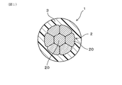
- FIG. 1 is a cross-sectional view of an insulated wire of Example 1.
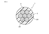
- FIG. It is sectional drawing which showed the modification of the insulated wire of Example 1.
- FIG. 1 is a cross-sectional view of an insulated wire of Example 1.
- the cross-sectional area of the conductor is 0.4 mm 2 or less.
- the cross-sectional area of the conductor is preferably 0.3 mm 2 or less, more preferably 0.25 mm 2 or less, still more preferably 0.2 mm 2 or less, from the viewpoint of ensuring the diameter reduction of the insulated wire. Even more preferably, it can be 0.18 mm 2 or less.
- the cross-sectional area of the conductor is secured in a suitable allowable current in automotive applications, in view of handling property during harnessed, preferably, 0.01 mm 2 or more, more preferably, 0.03 mm 2 or more, more preferably Can be 0.05 mm 2 or more.
- the conductor can be composed of a single metal wire or a plurality of metal wires. In the latter case, the conductor can be configured to have a plurality of twisted metal wires.
- the conductor can also have a circular outer shape when viewed from the conductor cross section. Such a circular shape can be formed by circularly compressing the conductor in the conductor radial direction.
- the conductor may have surface irregularities along the outer shape of the metal strand. From the viewpoint of reducing the diameter of the insulated wire and the appearance, the conductor may have a circular outer shape when viewed from the conductor cross section.
- Examples of the conductor material include Cu, Cu alloy, Al, and Al alloy.
- the conductor can have a plating layer formed of Ni plating, Ni alloy plating, or the like on the surface from the viewpoint of improving high-temperature fluid resistance.
- the insulator includes a polymer having S or F in the main chain. This makes it difficult for the insulator to be attacked by the high-temperature AT fluid or CVT fluid in the AT or CVT, and an insulated wire excellent in high-temperature fluid resistance can be obtained.
- the insulator may include a polymer having S in the main chain or a polymer having F in the main chain.
- the insulator preferably contains a polymer having F in the main chain from the viewpoint of easily exhibiting high-temperature fluid resistance and ensuring the electric wire density.
- polysulfone resin examples include polysulfone (PSU), polyethersulfone (PES), polyphenylsulfone (PPSU), and the like. These can be used alone or in combination of two or more.
- polysulfone resin examples include polysulfone (PSU), polyethersulfone (PES), polyphenylsulfone (PPSU), and the like. These can be used alone or in combination of two or more.
- polymer having F in the main chain include fluororesins and fluororubbers (including elastomers). These can be used alone or in combination of two or more.
- fluororesin examples include ethylene-tetrafluoroethylene copolymer (ETFE), polytetrafluoroethylene (PTFE), tetrafluoroethylene-perfluoroalkyl vinyl ether copolymer (PFA), tetrafluoroethylene-hexa.
- ETFE ethylene-tetrafluoroethylene copolymer
- PTFE polytetrafluoroethylene
- PFA tetrafluoroethylene-perfluoroalkyl vinyl ether copolymer
- FEP fluoropropylene copolymer
- PVDF vinylidene fluoride resin
- fluororubber examples include vinylidene fluoride rubber (FKM), tetrafluoroethylene-propylene rubber (FEPM), tetrafluoroethylene-perfluoromethyl vinyl ether rubber (FFKM), and the like. . These can be used alone or in combination of two or more.
- FKM vinylidene fluoride rubber
- FEPM tetrafluoroethylene-propylene rubber
- FFKM tetrafluoroethylene-perfluoromethyl vinyl ether rubber
- the insulator may include a resin having a melting point of 200 ° C. or higher.
- the wear resistance of the insulator is improved by the resin having a melting point of 200 ° C. or higher. Therefore, an insulated wire having excellent wear resistance can be obtained.
- the melting point is preferably 250 ° C. or higher, more preferably 275 ° C. or higher, and still more preferably 300 ° C. or higher from the viewpoint of improving wear resistance.
- Specific examples of the resin having a melting point of 200 ° C. or higher include a resin having F in the main chain and a melting point of 200 ° C. or higher. More specifically, the resin having a melting point of 200 ° C.
- F in the main chain includes ETFE (melting point: 270 ° C.), PTFE (melting point: 327 ° C.), PFA (melting point: 310 ° C.), FEP ( Fluorine resin such as melting point: 260 ° C. can be exemplified. These can be used alone or in combination of two or more.
- examples of the resin having S in the main chain and having a melting point of 200 ° C. or higher include PPS (melting point: 278 ° C.).
- PPS melting point: 278 ° C.
- the insulator may contain one or more of various additives usually used for insulators of insulated wires.
- the additive include fillers, flame retardants, antioxidants, anti-aging agents, lubricants, plasticizers, copper damage inhibitors, pigments and the like.
- the thickness of the insulator is 0.05 mm or more.
- the thickness of the insulator is preferably 0.07 mm or more, more preferably 0.1 mm or more, and further preferably 0.15 mm or more from the viewpoint of suppressing dielectric breakdown.
- the thickness of the insulator is preferably 0.35 mm or less, more preferably 0.33 mm or less, and still more preferably 0.3 mm or less, from the viewpoint of promoting the reduction of the diameter of the insulated wire and ensuring the wire density. It can be.
- the density of the insulator can be 1.5 g / cm 3 or more. In this case, the electric wire density is easily set to 3.1 g / cm 3 or more.
- the density of the insulator is a value calculated from the mass of the insulator (g) / the volume of the insulator (cm 3 ).
- the density of the insulator is preferably 1.55 g / cm 3 or more, more preferably 1.6 g / cm 3 or more, and still more preferably 1.65 g / cm from the viewpoint of facilitating securing the electric wire density. It can be 3 or more, and even more preferably 1.7 g / cm 3 or more.
- the density of the insulator can be set to, for example, 2.5 g / cm 3 or less from the viewpoint of availability.
- the wire density is 3.1 g / cm 3 or more.
- the electric wire density is an index related to electric wire fatigue when a thin insulated wire is arranged in an AT or CVT and is shaken by an AT fluid or a CVT fluid.
- the wire density ⁇ s is preferably as large as possible from the viewpoint of reducing fluctuations due to fluid. However, if the wire density ⁇ s becomes excessively large, it will hinder weight reduction of the wire harness. Therefore, the wire density ⁇ s can be preferably 8 g / cm 3 or less, more preferably 7.5 g / cm 3 or less, and even more preferably 7 g / cm 3 or less.
- the electric wire density ⁇ s is a value calculated from mass (g) per 1 m of insulated wire / volume (cm 3 ) per 1 m of insulated wire.
- Example 1 The insulated wire of Example 1 is demonstrated using FIG.
- the insulated wire 1 of this example includes a conductor 2 and an insulator 3 that covers the outer periphery of the conductor 2.
- the cross-sectional area of the conductor 2 is 0.4 mm 2 or less.
- the insulator 3 includes a polymer having S or F in the main chain and has a thickness of 0.05 mm or more.
- the electric wire density is 3.1 g / cm 3 or more.
- the density of the insulator 3 is 1.5 g / cm 3 or more.
- the insulator 3 is composed of a polysulfone resin as a polymer having S in the main chain, or a fluororesin or fluororubber as a polymer having F in the main chain.
- the insulated wire 1 is used in the state immersed in AT fluid or CVT fluid.
- the conductor 2 is comprised from the several metal strand 20 twisted together.
- FIG. 1 shows an example in which the conductor 2 has a circular outer shape by twisting a plurality of metal strands 20 and compressing them circularly.
- the conductor 2 does not need to be circularly compressed as illustrated in FIG.
- An insulated wire of each sample was produced by extruding and coating a predetermined insulator material at a predetermined thickness (center value) on the outer periphery of a conductor having a predetermined cross-sectional area shown in Table 1 described later.
- the wire weight (g / m), the wire outer diameter (mm), the wire density (g / cm 3 ), the density of the insulator (g / cm 3 ), the gravity that the wire receives (N / m), The buoyancy (N / m) in the fluid and the weight / buoyancy ratio were determined.
- AT fluid (ATF) having a density of 0.85 (g / cm 3 ) was used.
- the weight / buoyancy value which is the ratio between the gravity received by each insulated wire and the buoyancy in the fluid, is used as an index of wire fatigue when each insulated wire is routed in an AT or CVT. Used as.
- the case where the ratio of weight / buoyancy was 3.65 or more was regarded as acceptable as it could suppress electric wire fatigue even when it was shaken by fluid.
- the case where the weight / buoyancy ratio was less than 3.65 was rejected as being unable to suppress wire fatigue when shaken by fluid.
- spark test In accordance with JASO D618: (2008), a spark test (applied voltage: 3 kV (rms)) was performed on each insulated wire. The case where dielectric breakdown did not occur was accepted and the case where dielectric breakdown occurred was rejected.
- Table 1 summarizes the configuration and evaluation results of each insulated wire.
- the insulated wires of Sample 1C and Sample 2C have a wire density of less than 3.1 g / cm 3 . Therefore, in the insulated wires of Sample 1C and Sample 2C, the weight / buoyancy ratio was lower than the specified value, and the wire fatigue resistance in the fluid was poor.
- the insulator is made of polypropylene, and is not made of a polymer having S or F in the main chain. Therefore, the insulated wire of Sample 3C was damaged by the high temperature AT fluid, and the high temperature fluid resistance was poor.
- the insulated wire of sample 4C has an insulator thickness of less than 0.05 mm. For this reason, dielectric breakdown occurred in the insulated wire of Sample 4C in the spark test.
- the insulated wires of Samples 1 to 4 have the specific configuration described above. Therefore, it can be said that the insulated wires of Samples 1 to 4 can suppress the wire fatigue even when the diameter is reduced and the wires are arranged in the AT or CVT and shaken by the AT fluid or the CVT fluid. In addition, it can be said that the insulated wires of Samples 1 to 4 are excellent in high temperature fluid resistance because the insulator is not easily eroded by high temperature AT fluid or CVT fluid in AT or CVT. In addition, it can be said that the insulated wires of Samples 1 to 4 hardly cause dielectric breakdown in the spark test.
Landscapes
- Physics & Mathematics (AREA)
- Spectroscopy & Molecular Physics (AREA)
- Chemical & Material Sciences (AREA)
- Chemical Kinetics & Catalysis (AREA)
- Insulated Conductors (AREA)
- Organic Insulating Materials (AREA)
Abstract
AT内やCVT内に配策されてATフルードやCVTフルードによって揺らされた場合でも、電線疲労を抑制可能な絶縁電線(1)を提供する。絶縁電線(1)は、導体(2)と、導体(2)の外周を覆う絶縁体(3)とを有している。導体(2)の断面積は、0.4mm2以下である。絶縁体(3)は、SまたはFを主鎖に有するポリマーを含み、厚みが0.05mm以上である。絶縁電線(1)の電線密度は、3.1g/cm3以上である。絶縁体(3)の密度は、1.5g/cm3以上であるとよい。
Description
本発明は、絶縁電線に関する。
従来、AT(Automatic Transmission)内やCVT(Continuously Variable Transmission)内に配策される絶縁電線としては、例えば、導体と、導体の外周に押出被覆された絶縁体とを有しており、導体には、NiめっきまたはNi合金めっきが施されており、絶縁体が、繰り返し単位内にスルホニル基を有するスルホニル基含有樹脂を少なくとも含有する樹脂組成物より構成されている絶縁電線が公知である(特許文献1参照)。
AT内やCVT内は、絶縁電線を配策するためのスペースが狭い。そのため、AT内やCVT内に配策される絶縁電線は、細径化が望まれている。しかしながら、実際に使用されている絶縁電線の導体断面積は0.5mm2以上である。今後、ワイヤーハーネスにおける回路数の増加に伴い、さらなる絶縁電線の細径化が要求されると考えられる。
ところで、AT内やCVT内では、走行中の車両の揺れや振動により、ATフルードやCVTフルードが揺らされ、フルード液面が上下する。また、ATフルードやCVTフルードは、AT内やCVT内にて循環されており、これによってもフルード液面が上下する。AT内やCVT内に配策される絶縁電線の細径化が進むと、絶縁電線の剛性が低下する。そのため、ATフルードやCVTフルードに浸かった絶縁電線は、フルード液面が上下することによってさらに揺らされやすくなる。その結果、AT内やCVT内にて絶縁電線が屈曲され、電線疲労が進みやすくなる。
上記問題を防ぐため、AT内やCVT内に絶縁電線を配策する際に、ATフルードやCVTフルードによって絶縁電線が揺らされないように配策することが考えられる。上記配策方法としては、例えば、絶縁電線をATフルードやCVTフルードと接触しないように配置したり、絶縁電線の固定箇所を増やしたりすることなどが挙げられる。しかしながら、このような手法は、絶縁電線の配策経路や配策形態の自由度を制限することになるため、望ましくない。
本発明は、上記背景に鑑みてなされたものであり、AT内やCVT内に配策されてATフルードやCVTフルードによって揺らされた場合でも、電線疲労を抑制可能な絶縁電線を提供しようとするものである。
本発明の一態様は、導体と、該導体の外周を覆う絶縁体と、を有する絶縁電線であって、
上記導体の断面積が0.4mm2以下であり、
上記絶縁体は、SまたはFを主鎖に有するポリマーを含み、厚みが0.05mm以上であり、
電線密度が3.1g/cm3以上である、絶縁電線にある。
上記導体の断面積が0.4mm2以下であり、
上記絶縁体は、SまたはFを主鎖に有するポリマーを含み、厚みが0.05mm以上であり、
電線密度が3.1g/cm3以上である、絶縁電線にある。
上記絶縁電線は、上記特定の構成を有している。そのため、上記絶縁電線は、細径化され、AT内やCVT内に配策されてATフルードやCVTフルードによって揺らされた場合でも、電線疲労を抑制することができる。また、上記絶縁電線は、AT内やCVT内で高温のATフルードやCVTフルードによって絶縁体が侵され難く、高温耐フルード性に優れる。また、上記絶縁電線は、スパーク試験での絶縁破壊も生じ難い。
上記絶縁電線において、導体の断面積は、0.4mm2以下である。導体の断面積が0.4mm2を超えると、ワイヤーハーネスにおける回路数の増加に伴う絶縁電線の細径化の要請に対応することができない。導体の断面積は、絶縁電線の細径化を確実なものとする観点から、好ましくは、0.3mm2以下、より好ましくは、0.25mm2以下、さらに好ましくは、0.2mm2以下、さらにより好ましくは、0.18mm2以下とすることができる。なお、導体の断面積は、自動車用途に好適な許容電流の確保、ハーネス加工時の取扱い性などの観点から、好ましくは、0.01mm2以上、より好ましくは、0.03mm2以上、さらに好ましくは、0.05mm2以上とすることができる。
導体は、単線の金属素線、あるいは、複数本の金属素線より構成することができる。後者の場合、導体は、撚り合わされた複数本の金属素線を有する構成とすることができる。また、導体は、導体断面で見て、外形が円形状の形状を呈することもできる。このような円形状の形状は、導体を、導体径方向で円形圧縮することにより形成することができる。他にも、導体は、金属素線の外形に沿った表面凹凸を有することもできる。導体は、絶縁電線の細径化、外観などの観点から、導体断面で見て、外形が円形状の形状を呈しているとよい。
導体の材料としては、例えば、Cu、Cu合金、Al、Al合金などを例示することができる。導体は、高温耐フルード性の向上などの観点から、Niめっき、Ni合金めっき等より構成されるめっき層を表面に有することができる。
上記絶縁電線において、絶縁体は、SまたはFを主鎖に有するポリマーを含んでいる。これにより、AT内やCVT内で高温のATフルードやCVTフルードによって絶縁体が侵され難くなり、高温耐フルード性に優れた絶縁電線が得られる。
絶縁体は、Sを主鎖に有するポリマーを含んでいてもよいし、Fを主鎖に有するポリマーを含んでいてもよい。絶縁体は、高温耐フルード性を発揮させやすく、電線密度を確保しやすいなどの観点から、好ましくは、Fを主鎖に有するポリマーを含んでいるとよい。
Sを主鎖に有するポリマーとしては、具体的には、例えば、ポリフェニレンサルファイド(PPS)やポリスルホン系樹脂などを例示することができる。ポリスルホン系樹脂としては、具体的には、ポリスルホン(PSU)、ポリエーテルスルホン(PES)、ポリフェニルスルホン(PPSU)などを例示することができる。これらは1種または2種以上併用することができる。また、Fを主鎖に有するポリマーとしては、具体的には、例えば、フッ素樹脂、フッ素ゴム(エラストマー含む)などを例示することができる。これらは1種または2種以上併用することができる。フッ素樹脂としては、具体的には、エチレン-テトラフルオロエチレン共重合体(ETFE)、ポリテトラフルオロエチレン(PTFE)、テトラフルオロエチレン-パーフルオロアルキルビニルエーテル共重合体(PFA)、テトラフルオロエチレン-ヘキサフルオロプロピレン共重合体(FEP)、フッ化ビニリデン樹脂(PVDF)などを例示することができる。これらは1種または2種以上併用することができる。フッ素ゴムとしては、具体的には、例えば、フッ化ビニリデン系ゴム(FKM)、テトラフルオロエチレン-プロピレンゴム(FEPM)、テトラフルオロエチレン-パーフルオロメチルビニルエーテルゴム(FFKM)などを例示することができる。これらは1種または2種以上併用することができる。
絶縁体は、融点が200℃以上の樹脂を含む構成とすることができる。この場合には、融点が200℃以上の樹脂により、絶縁体の耐摩耗性が向上する。そのため、耐摩耗性に優れた絶縁電線が得られる。上記融点は、耐摩耗性向上などの観点から、好ましくは、250℃以上、より好ましくは、275℃以上、さらに好ましくは、300℃以上とすることができる。融点が200℃以上の樹脂としては、具体的には、融点が200℃以上である、Fを主鎖に有する樹脂などを例示することができる。融点が200℃以上である、Fを主鎖に有する樹脂としては、より具体的には、ETFE(融点:270℃)、PTFE(融点:327℃)、PFA(融点:310℃)、FEP(融点:260℃)などのフッ素樹脂を例示することができる。これらは1種または2種以上併用することができる。また、融点が200℃以上である、Sを主鎖に有する樹脂としては、より具体的には、PPS(融点:278℃)などを例示することができる。これは1種または分子量等が異なるグレード違いの2種以上を併用することができる。
絶縁体は、SまたはFを主鎖に有する樹脂以外にも、絶縁電線の絶縁体に通常用いられる各種の添加剤を1種または2種以上含むことができる。添加剤としては、例えば、充填剤、難燃剤、酸化防止剤、老化防止剤、滑剤、可塑剤、銅害防止剤、顔料などを例示することができる。
上記絶縁電線において、絶縁体の厚みは、0.05mm以上である。絶縁体の厚みが0.05mm未満になると、JASO D618:2008に準拠してスパーク試験(印加電圧:3kV(rms))を実施した際に、絶縁破壊が発生する。そのため、絶縁電線としての使用が困難になる。絶縁体の厚みは、絶縁破壊の抑制などの観点から、好ましくは、0.07mm以上、より好ましくは、0.1mm以上、さらに好ましくは、0.15mm以上とすることができる。なお、絶縁体の厚みは、絶縁電線の細径化促進、電線密度の確保などの観点から、好ましくは、0.35mm以下、より好ましくは、0.33mm以下、さらに好ましくは、0.3mm以下とすることができる。
上記絶縁電線において、絶縁体の密度は、1.5g/cm3以上とすることができる。この場合には、電線密度を3.1g/cm3以上としやすくなる。なお、絶縁体の密度は、絶縁体の質量(g)/絶縁体の体積(cm3)より算出される値である。絶縁体の密度は、電線密度を確保しやすくなるなどの観点から、好ましくは、1.55g/cm3以上、より好ましくは、1.6g/cm3以上、さらに好ましくは、1.65g/cm3以上、さらにより好ましくは、1.7g/cm3以上とすることができる。なお、絶縁体の密度は、入手容易性などの観点から、例えば、2.5g/cm3以下とすることができる。
上記絶縁電線において、電線密度は、3.1g/cm3以上である。電線密度は、細径化された絶縁電線がAT内やCVT内に配策されてATフルードやCVTフルードによって揺らされた場合における電線疲労と関係のある指標である。
すなわち、絶縁電線がATフルードまたはCVTフルード(以下、単にフルードということがある。)に浸かった場合、絶縁電線は、フルードから浮力を受ける。フルードの密度をρf、フルードに浸かった部分の絶縁電線の体積をV、重力加速度をgとすると、浮力Fbは、以下の式1で表される。
Fb=ρf×V×g・・・式1
絶縁電線が受ける浮力が大きいほど、フルードの液面の動きによって絶縁電線が揺らされ、電線疲労が進むことになる。絶縁電線は、電線密度に比例した重力を受ける。この重力が大きいほど、浮力の影響が打ち消され、絶縁電線がフルードによって揺らされる度合が小さくなり、電線疲労が生じ難くなる。絶縁電線の電線密度をρs、フルードに浸かった部分の絶縁電線の体積をV、重力加速度をgとすると、絶縁電線が受ける重力Fは、以下の式2で表される。
F=ρs×V×g・・・式2
上記式1、式2より、絶縁電線が受ける重力Fとフルードに浸かった絶縁電線が受ける浮力Fbとの比率F/Fbは、以下の式3で表される。
F/Fb=ρs/ρf・・・式3
この比率が大きいほど、フルードの液面の動きによる電線疲労への影響が小さくなる。ATフルードおよびCVTフルードの密度は、同等であり一定値であるとみなせる。したがって、電線密度ρsを選ぶことで、絶縁電線がフルードによって揺らされた場合でも、電線疲労を抑制することが可能となるのである。後述する実験例に示されるように、電線密度ρsが3.1g/cm3以上であると、電線疲労の抑制効果を得ることができる。一方、電線密度ρsが3.1g/cm3未満になると、フルードによって絶縁電線が揺らされやすく、電線疲労を抑制することが困難になる。電線密度ρsは、フルードによる揺れを少なくする観点から大きいほど好ましい。しかし、電線密度ρsが過度に大きくなると、ワイヤーハーネスの軽量化の妨げになる。そのため、電線密度ρsは、好ましくは、8g/cm3以下、より好ましくは、7.5g/cm3以下、さらに好ましくは、7g/cm3以下とすることができる。なお、電線密度ρsは、絶縁電線1m当たりの質量(g)/絶縁電線1m当たりの体積(cm3)より算出される値である。
Fb=ρf×V×g・・・式1
絶縁電線が受ける浮力が大きいほど、フルードの液面の動きによって絶縁電線が揺らされ、電線疲労が進むことになる。絶縁電線は、電線密度に比例した重力を受ける。この重力が大きいほど、浮力の影響が打ち消され、絶縁電線がフルードによって揺らされる度合が小さくなり、電線疲労が生じ難くなる。絶縁電線の電線密度をρs、フルードに浸かった部分の絶縁電線の体積をV、重力加速度をgとすると、絶縁電線が受ける重力Fは、以下の式2で表される。
F=ρs×V×g・・・式2
上記式1、式2より、絶縁電線が受ける重力Fとフルードに浸かった絶縁電線が受ける浮力Fbとの比率F/Fbは、以下の式3で表される。
F/Fb=ρs/ρf・・・式3
この比率が大きいほど、フルードの液面の動きによる電線疲労への影響が小さくなる。ATフルードおよびCVTフルードの密度は、同等であり一定値であるとみなせる。したがって、電線密度ρsを選ぶことで、絶縁電線がフルードによって揺らされた場合でも、電線疲労を抑制することが可能となるのである。後述する実験例に示されるように、電線密度ρsが3.1g/cm3以上であると、電線疲労の抑制効果を得ることができる。一方、電線密度ρsが3.1g/cm3未満になると、フルードによって絶縁電線が揺らされやすく、電線疲労を抑制することが困難になる。電線密度ρsは、フルードによる揺れを少なくする観点から大きいほど好ましい。しかし、電線密度ρsが過度に大きくなると、ワイヤーハーネスの軽量化の妨げになる。そのため、電線密度ρsは、好ましくは、8g/cm3以下、より好ましくは、7.5g/cm3以下、さらに好ましくは、7g/cm3以下とすることができる。なお、電線密度ρsは、絶縁電線1m当たりの質量(g)/絶縁電線1m当たりの体積(cm3)より算出される値である。
なお、上述した各構成は、上述した各作用効果等を得るなどのために必要に応じて任意に組み合わせることができる。
以下、実施例の絶縁電線について、図面を用いて説明する。
(実施例1)
実施例1の絶縁電線について、図1を用いて説明する。図1に示されるように、本例の絶縁電線1は、導体2と、導体2の外周を覆う絶縁体3とを有している。導体2の断面積は、0.4mm2以下である。絶縁体3は、SまたはFを主鎖に有するポリマーを含み、厚みが0.05mm以上である。電線密度は、3.1g/cm3以上である。
実施例1の絶縁電線について、図1を用いて説明する。図1に示されるように、本例の絶縁電線1は、導体2と、導体2の外周を覆う絶縁体3とを有している。導体2の断面積は、0.4mm2以下である。絶縁体3は、SまたはFを主鎖に有するポリマーを含み、厚みが0.05mm以上である。電線密度は、3.1g/cm3以上である。
本例では、絶縁体3の密度は、1.5g/cm3以上である。絶縁体3は、Sを主鎖に有するポリマーとしてのポリスルホン系樹脂、または、Fを主鎖に有するポリマーとしてのフッ素樹脂またはフッ素ゴムより構成されている。絶縁電線1は、ATフルードまたはCVTフルードに浸漬した状態で使用されるものである。
なお、導体2は、撚り合わされた複数本の金属素線20より構成されている。図1では、導体2は、複数本の金属素線20が撚り合わされて円形圧縮されることにより、外形が円形状の形状を呈している例が示されている。なお、導体2は、図2に例示されるように、円形圧縮されていなくてもよい。
<実験例>
以下、実験例を用いてより具体的に説明する。
<絶縁電線の作製>
直径0.15mmの軟銅線を9本撚り合わせた後、円形圧縮することにより、断面積0.16mm2の導体を準備した。同様に、直径0.13mmの軟銅線を19本撚り合わせることにより、断面積0.24mm2の導体を準備した。直径0.16mmの軟銅線を19本撚り合わせることにより、断面積0.38mm2の導体を準備した。
以下、実験例を用いてより具体的に説明する。
<絶縁電線の作製>
直径0.15mmの軟銅線を9本撚り合わせた後、円形圧縮することにより、断面積0.16mm2の導体を準備した。同様に、直径0.13mmの軟銅線を19本撚り合わせることにより、断面積0.24mm2の導体を準備した。直径0.16mmの軟銅線を19本撚り合わせることにより、断面積0.38mm2の導体を準備した。
後述の表1に示される所定の断面積を有する導体の外周に、所定の絶縁体材料を所定の厚み(中心値)にて押し出し被覆することにより、各試料の絶縁電線を作製した。各絶縁電線について、電線重量(g/m)、電線外径(mm)、電線密度(g/cm3)、絶縁体の密度(g/cm3)、電線が受ける重力(N/m)、フルード中での浮力(N/m)、重量/浮力の比率を求めた。なお、本実験例では、密度0.85(g/cm3)のATフルード(ATF)を用いた。
(フルード中での耐電線疲労性)
本実験例では、各絶縁電線が受ける重力と上記フルード中での浮力との比率である重量/浮力の値を、各絶縁電線がAT内やCVT内に配策された状態における電線疲労の指標として用いた。この重量/浮力の比率が、3.65以上であった場合を、フルードによって揺らされた場合でも、電線疲労を抑制することができるとして合格とした。重量/浮力の比率が、3.65未満であった場合を、フルードによって揺らされた場合に、電線疲労を抑制することができないとして不合格とした。
本実験例では、各絶縁電線が受ける重力と上記フルード中での浮力との比率である重量/浮力の値を、各絶縁電線がAT内やCVT内に配策された状態における電線疲労の指標として用いた。この重量/浮力の比率が、3.65以上であった場合を、フルードによって揺らされた場合でも、電線疲労を抑制することができるとして合格とした。重量/浮力の比率が、3.65未満であった場合を、フルードによって揺らされた場合に、電線疲労を抑制することができないとして不合格とした。
(高温耐フルード性)
JASO D618:(2008)に準拠し、各絶縁電線について、上記ATフルードによる耐液性試験を実施した。但し、ATフルードの試験温度は、160℃とした。上記耐液性試験に合格したものを高温耐フルード性に優れるとした。上記耐液性試験に不合格であったものを高温耐フルード性がないとした。
JASO D618:(2008)に準拠し、各絶縁電線について、上記ATフルードによる耐液性試験を実施した。但し、ATフルードの試験温度は、160℃とした。上記耐液性試験に合格したものを高温耐フルード性に優れるとした。上記耐液性試験に不合格であったものを高温耐フルード性がないとした。
(スパーク試験)
JASO D618:(2008)に準拠し、各絶縁電線について、スパーク試験(印加電圧:3kV(rms))を実施した。絶縁破壊が発生しなかった場合を合格、絶縁破壊が発生した場合を不合格とした。
JASO D618:(2008)に準拠し、各絶縁電線について、スパーク試験(印加電圧:3kV(rms))を実施した。絶縁破壊が発生しなかった場合を合格、絶縁破壊が発生した場合を不合格とした。
各絶縁電線の構成、評価結果をまとめて表1に示す。
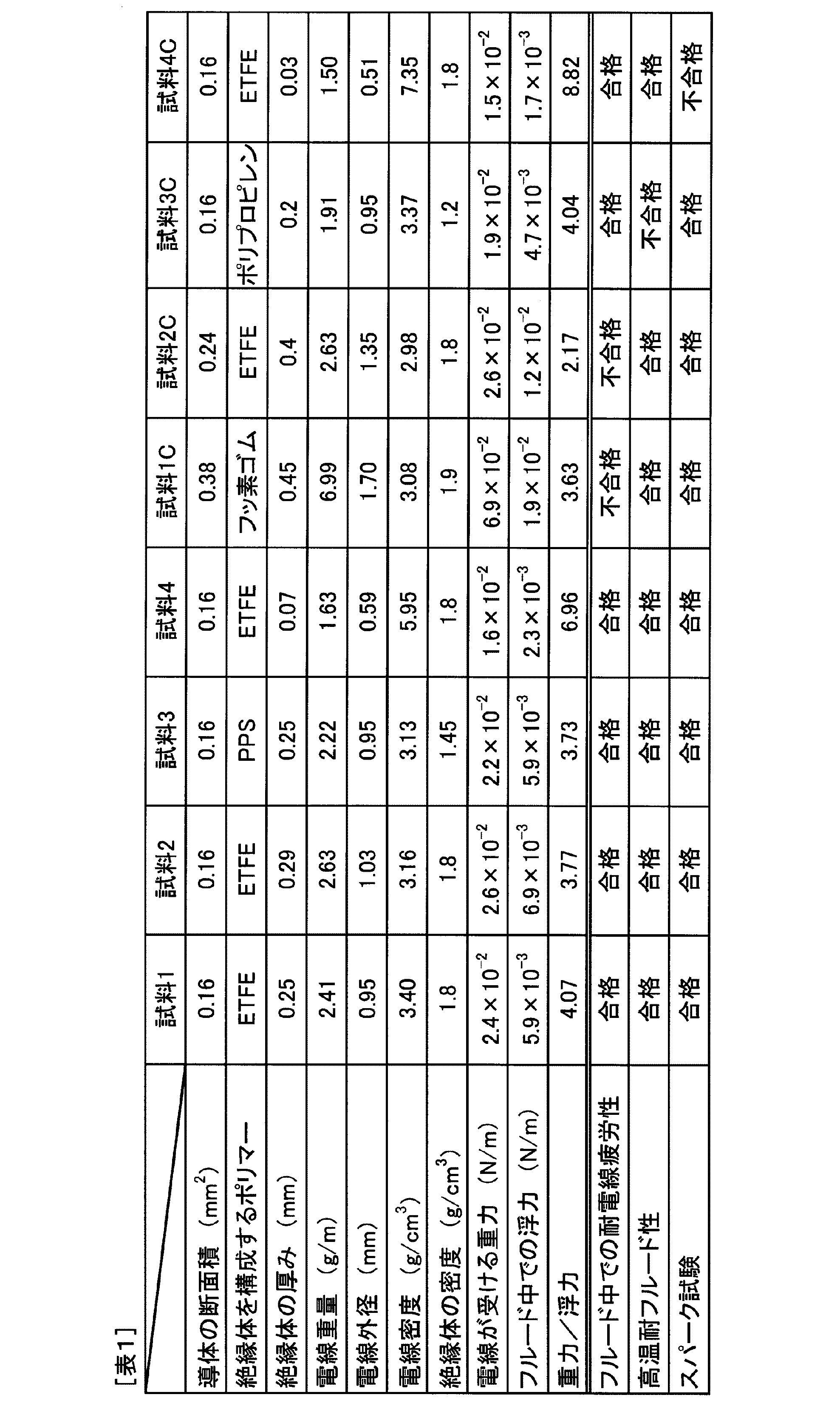
表1によれば、以下のことがわかる。試料1Cおよび試料2Cの絶縁電線は、電線密度が3.1g/cm3未満である。そのため、試料1Cおよび試料2Cの絶縁電線は、重量/浮力の比率が規定値を下回り、フルード中での耐電線疲労性が悪かった。
試料3Cの絶縁電線は、絶縁体がポリプロピレンより構成されており、SまたはFを主鎖に有するポリマーより構成されていない。そのため、試料3Cの絶縁電線は、高温のATフルードによって絶縁体が侵され、高温耐フルード性が悪かった。
試料4Cの絶縁電線は、絶縁体の厚みが0.05mm未満である。そのため、試料4Cの絶縁電線は、スパーク試験で絶縁破壊が発生した。
これらに対し、試料1~4の絶縁電線は、上述した特定の構成を有している。そのため、試料1~4の絶縁電線は、細径化され、AT内やCVT内に配策されてATフルードやCVTフルードによって揺らされた場合でも、電線疲労を抑制することができるといえる。また、試料1~4の絶縁電線は、AT内やCVT内で高温のATフルードやCVTフルードによって絶縁体が侵され難く、高温耐フルード性に優れるといえる。また、試料1~4の絶縁電線は、スパーク試験での絶縁破壊も生じ難いといえる。
以上、本発明の実施例について詳細に説明したが、本発明は上記実施例、実験例に限定されるものではなく、本発明の趣旨を損なわない範囲内で種々の変更が可能である。
Claims (3)
- 導体と、該導体の外周を覆う絶縁体と、を有する絶縁電線であって、
上記導体の断面積が0.4mm2以下であり、
上記絶縁体は、SまたはFを主鎖に有するポリマーを含み、厚みが0.05mm以上であり、
電線密度が3.1g/cm3以上である、絶縁電線。 - 上記絶縁体の密度が1.5g/cm3以上である、請求項1に記載の絶縁電線。
- 上記絶縁体は、融点が200℃以上の樹脂を含む、請求項1または2に記載の絶縁電線。
Priority Applications (3)
| Application Number | Priority Date | Filing Date | Title |
|---|---|---|---|
| DE112017001743.2T DE112017001743T5 (de) | 2016-03-31 | 2017-03-15 | lsolierter Draht |
| CN201780001672.6A CN107615405A (zh) | 2016-03-31 | 2017-03-15 | 绝缘电线 |
| US15/768,639 US20180301239A1 (en) | 2016-03-31 | 2017-03-15 | Insulated wire |
Applications Claiming Priority (2)
| Application Number | Priority Date | Filing Date | Title |
|---|---|---|---|
| JP2016-071149 | 2016-03-31 | ||
| JP2016071149A JP6194976B1 (ja) | 2016-03-31 | 2016-03-31 | 絶縁電線 |
Publications (1)
| Publication Number | Publication Date |
|---|---|
| WO2017169798A1 true WO2017169798A1 (ja) | 2017-10-05 |
Family
ID=59854902
Family Applications (1)
| Application Number | Title | Priority Date | Filing Date |
|---|---|---|---|
| PCT/JP2017/010472 Ceased WO2017169798A1 (ja) | 2016-03-31 | 2017-03-15 | 絶縁電線 |
Country Status (5)
| Country | Link |
|---|---|
| US (1) | US20180301239A1 (ja) |
| JP (1) | JP6194976B1 (ja) |
| CN (1) | CN107615405A (ja) |
| DE (1) | DE112017001743T5 (ja) |
| WO (1) | WO2017169798A1 (ja) |
Families Citing this family (4)
| Publication number | Priority date | Publication date | Assignee | Title |
|---|---|---|---|---|
| WO2021039222A1 (ja) | 2019-08-30 | 2021-03-04 | 住友電気工業株式会社 | 多芯ケーブル、ハーネス |
| WO2024048189A1 (ja) * | 2022-08-29 | 2024-03-07 | ダイキン工業株式会社 | 被覆電線および被覆電線の製造方法 |
| JP7534686B2 (ja) * | 2022-08-29 | 2024-08-15 | ダイキン工業株式会社 | 被覆電線および被覆電線の製造方法 |
| WO2025019772A1 (en) * | 2023-07-19 | 2025-01-23 | Team Industries, Inc. | A continuously variable transmission with a select revolutions per minute output |
Citations (3)
| Publication number | Priority date | Publication date | Assignee | Title |
|---|---|---|---|---|
| WO2011118717A1 (ja) * | 2010-03-25 | 2011-09-29 | 古河電気工業株式会社 | 発泡電線及びその製造方法 |
| JP2012230847A (ja) * | 2011-04-27 | 2012-11-22 | Auto Network Gijutsu Kenkyusho:Kk | 絶縁電線 |
| JP2013161572A (ja) * | 2012-02-02 | 2013-08-19 | Swcc Showa Cable Systems Co Ltd | 耐熱電線 |
Family Cites Families (5)
| Publication number | Priority date | Publication date | Assignee | Title |
|---|---|---|---|---|
| CN201084491Y (zh) * | 2007-10-12 | 2008-07-09 | 中利科技集团股份有限公司 | 海洋作业用的浮力信号电缆 |
| CN202384030U (zh) * | 2011-11-10 | 2012-08-15 | 天津德芃科技集团有限公司 | 一种绝缘建筑用线 |
| JP2015141820A (ja) | 2014-01-29 | 2015-08-03 | 株式会社オートネットワーク技術研究所 | 絶縁電線 |
| CN203941710U (zh) * | 2014-03-04 | 2014-11-12 | 上海福尔欣线缆有限公司 | 汽车发动机氮氧化物传感器连接超高耐温氟绝缘电线 |
| CN204390779U (zh) * | 2015-02-15 | 2015-06-10 | 马秀芬 | 一种耐高压零浮力水下电缆 |
-
2016
- 2016-03-31 JP JP2016071149A patent/JP6194976B1/ja active Active
-
2017
- 2017-03-15 DE DE112017001743.2T patent/DE112017001743T5/de active Pending
- 2017-03-15 CN CN201780001672.6A patent/CN107615405A/zh active Pending
- 2017-03-15 US US15/768,639 patent/US20180301239A1/en not_active Abandoned
- 2017-03-15 WO PCT/JP2017/010472 patent/WO2017169798A1/ja not_active Ceased
Patent Citations (3)
| Publication number | Priority date | Publication date | Assignee | Title |
|---|---|---|---|---|
| WO2011118717A1 (ja) * | 2010-03-25 | 2011-09-29 | 古河電気工業株式会社 | 発泡電線及びその製造方法 |
| JP2012230847A (ja) * | 2011-04-27 | 2012-11-22 | Auto Network Gijutsu Kenkyusho:Kk | 絶縁電線 |
| JP2013161572A (ja) * | 2012-02-02 | 2013-08-19 | Swcc Showa Cable Systems Co Ltd | 耐熱電線 |
Also Published As
| Publication number | Publication date |
|---|---|
| JP6194976B1 (ja) | 2017-09-13 |
| CN107615405A (zh) | 2018-01-19 |
| DE112017001743T5 (de) | 2018-12-27 |
| US20180301239A1 (en) | 2018-10-18 |
| JP2017183173A (ja) | 2017-10-05 |
Similar Documents
| Publication | Publication Date | Title |
|---|---|---|
| JP6194976B1 (ja) | 絶縁電線 | |
| JP6207252B2 (ja) | 高屈曲電線 | |
| JP2005203334A (ja) | 絶縁ワイヤおよびその製造方法 | |
| KR20170080632A (ko) | 절연 와이어 및 회전 전기 | |
| JP2008251295A (ja) | 絶縁電線 | |
| JP2019091562A (ja) | ツイストペアケーブル | |
| JP6406098B2 (ja) | 絶縁電線 | |
| US11037702B2 (en) | High frequency cable comprising a center conductor having a first wire stranded by plural second wires that provide corners free of gaps | |
| EP3113190B1 (en) | Stranded conductor and insulated wire | |
| KR20110122205A (ko) | 가교 외부 층이 있는 다층 절연된 도체 | |
| JP2007519180A (ja) | ヒドロフルオロカーボンポリマー組成物 | |
| JP6645350B2 (ja) | 低エアリーク電線 | |
| CN111492445B (zh) | 电缆 | |
| KR20210083186A (ko) | 전기 절연 케이블 | |
| JP4601915B2 (ja) | 接続用リード線 | |
| WO2015115157A1 (ja) | 絶縁電線 | |
| JP2015167092A (ja) | 絶縁電線 | |
| JP7622633B2 (ja) | 多芯ケーブル、ハーネス | |
| JP2011249268A (ja) | 含フッ素エラストマ被覆電線、及び含フッ素エラストマ被覆電線の製造方法 | |
| JP2025021061A (ja) | 耐熱電線 | |
| JP2015115142A (ja) | 絶縁電線 | |
| WO2019124455A1 (ja) | ケーブル | |
| JPH07272542A (ja) | フッ素樹脂絶縁電線 | |
| JP2016054049A (ja) | 電線及びその製造方法 | |
| JP2015191773A (ja) | 絶縁電線およびワイヤーハーネス |
Legal Events
| Date | Code | Title | Description |
|---|---|---|---|
| WWE | Wipo information: entry into national phase |
Ref document number: 15768639 Country of ref document: US |
|
| 121 | Ep: the epo has been informed by wipo that ep was designated in this application |
Ref document number: 17774342 Country of ref document: EP Kind code of ref document: A1 |
|
| 122 | Ep: pct application non-entry in european phase |
Ref document number: 17774342 Country of ref document: EP Kind code of ref document: A1 |