WO2017169537A1 - タービン翼の脱水素処理方法 - Google Patents
タービン翼の脱水素処理方法 Download PDFInfo
- Publication number
- WO2017169537A1 WO2017169537A1 PCT/JP2017/008808 JP2017008808W WO2017169537A1 WO 2017169537 A1 WO2017169537 A1 WO 2017169537A1 JP 2017008808 W JP2017008808 W JP 2017008808W WO 2017169537 A1 WO2017169537 A1 WO 2017169537A1
- Authority
- WO
- WIPO (PCT)
- Prior art keywords
- steam
- ground
- turbine
- turbine blade
- temperature
- Prior art date
- Legal status (The legal status is an assumption and is not a legal conclusion. Google has not performed a legal analysis and makes no representation as to the accuracy of the status listed.)
- Ceased
Links
Images


Classifications
-
- C—CHEMISTRY; METALLURGY
- C21—METALLURGY OF IRON
- C21D—MODIFYING THE PHYSICAL STRUCTURE OF FERROUS METALS; GENERAL DEVICES FOR HEAT TREATMENT OF FERROUS OR NON-FERROUS METALS OR ALLOYS; MAKING METAL MALLEABLE, e.g. BY DECARBURISATION OR TEMPERING
- C21D1/00—General methods or devices for heat treatment, e.g. annealing, hardening, quenching or tempering
- C21D1/34—Methods of heating
-
- C—CHEMISTRY; METALLURGY
- C21—METALLURGY OF IRON
- C21D—MODIFYING THE PHYSICAL STRUCTURE OF FERROUS METALS; GENERAL DEVICES FOR HEAT TREATMENT OF FERROUS OR NON-FERROUS METALS OR ALLOYS; MAKING METAL MALLEABLE, e.g. BY DECARBURISATION OR TEMPERING
- C21D3/00—Diffusion processes for extraction of non-metals; Furnaces therefor
- C21D3/02—Extraction of non-metals
- C21D3/06—Extraction of hydrogen
-
- C—CHEMISTRY; METALLURGY
- C21—METALLURGY OF IRON
- C21D—MODIFYING THE PHYSICAL STRUCTURE OF FERROUS METALS; GENERAL DEVICES FOR HEAT TREATMENT OF FERROUS OR NON-FERROUS METALS OR ALLOYS; MAKING METAL MALLEABLE, e.g. BY DECARBURISATION OR TEMPERING
- C21D9/00—Heat treatment, e.g. annealing, hardening, quenching or tempering, adapted for particular articles; Furnaces therefor
-
- C—CHEMISTRY; METALLURGY
- C21—METALLURGY OF IRON
- C21D—MODIFYING THE PHYSICAL STRUCTURE OF FERROUS METALS; GENERAL DEVICES FOR HEAT TREATMENT OF FERROUS OR NON-FERROUS METALS OR ALLOYS; MAKING METAL MALLEABLE, e.g. BY DECARBURISATION OR TEMPERING
- C21D9/00—Heat treatment, e.g. annealing, hardening, quenching or tempering, adapted for particular articles; Furnaces therefor
- C21D9/0068—Heat treatment, e.g. annealing, hardening, quenching or tempering, adapted for particular articles; Furnaces therefor for particular articles not mentioned below
-
- F—MECHANICAL ENGINEERING; LIGHTING; HEATING; WEAPONS; BLASTING
- F01—MACHINES OR ENGINES IN GENERAL; ENGINE PLANTS IN GENERAL; STEAM ENGINES
- F01D—NON-POSITIVE DISPLACEMENT MACHINES OR ENGINES, e.g. STEAM TURBINES
- F01D25/00—Component parts, details, or accessories, not provided for in, or of interest apart from, other groups
-
- F—MECHANICAL ENGINEERING; LIGHTING; HEATING; WEAPONS; BLASTING
- F01—MACHINES OR ENGINES IN GENERAL; ENGINE PLANTS IN GENERAL; STEAM ENGINES
- F01D—NON-POSITIVE DISPLACEMENT MACHINES OR ENGINES, e.g. STEAM TURBINES
- F01D25/00—Component parts, details, or accessories, not provided for in, or of interest apart from, other groups
- F01D25/08—Cooling; Heating; Heat-insulation
- F01D25/10—Heating, e.g. warming-up before starting
-
- F—MECHANICAL ENGINEERING; LIGHTING; HEATING; WEAPONS; BLASTING
- F01—MACHINES OR ENGINES IN GENERAL; ENGINE PLANTS IN GENERAL; STEAM ENGINES
- F01D—NON-POSITIVE DISPLACEMENT MACHINES OR ENGINES, e.g. STEAM TURBINES
- F01D5/00—Blades; Blade-carrying members; Heating, heat-insulating, cooling or antivibration means on the blades or the members
- F01D5/12—Blades
-
- F—MECHANICAL ENGINEERING; LIGHTING; HEATING; WEAPONS; BLASTING
- F01—MACHINES OR ENGINES IN GENERAL; ENGINE PLANTS IN GENERAL; STEAM ENGINES
- F01D—NON-POSITIVE DISPLACEMENT MACHINES OR ENGINES, e.g. STEAM TURBINES
- F01D9/00—Stators
- F01D9/02—Nozzles; Nozzle boxes; Stator blades; Guide conduits, e.g. individual nozzles
-
- F—MECHANICAL ENGINEERING; LIGHTING; HEATING; WEAPONS; BLASTING
- F01—MACHINES OR ENGINES IN GENERAL; ENGINE PLANTS IN GENERAL; STEAM ENGINES
- F01K—STEAM ENGINE PLANTS; STEAM ACCUMULATORS; ENGINE PLANTS NOT OTHERWISE PROVIDED FOR; ENGINES USING SPECIAL WORKING FLUIDS OR CYCLES
- F01K13/00—General layout or general methods of operation of complete plants
- F01K13/02—Controlling, e.g. stopping or starting
-
- F—MECHANICAL ENGINEERING; LIGHTING; HEATING; WEAPONS; BLASTING
- F01—MACHINES OR ENGINES IN GENERAL; ENGINE PLANTS IN GENERAL; STEAM ENGINES
- F01K—STEAM ENGINE PLANTS; STEAM ACCUMULATORS; ENGINE PLANTS NOT OTHERWISE PROVIDED FOR; ENGINES USING SPECIAL WORKING FLUIDS OR CYCLES
- F01K21/00—Steam engine plants not otherwise provided for
- F01K21/06—Treating live steam, other than thermodynamically, e.g. for fighting deposits in engine
-
- F—MECHANICAL ENGINEERING; LIGHTING; HEATING; WEAPONS; BLASTING
- F01—MACHINES OR ENGINES IN GENERAL; ENGINE PLANTS IN GENERAL; STEAM ENGINES
- F01K—STEAM ENGINE PLANTS; STEAM ACCUMULATORS; ENGINE PLANTS NOT OTHERWISE PROVIDED FOR; ENGINES USING SPECIAL WORKING FLUIDS OR CYCLES
- F01K23/00—Plants characterised by more than one engine delivering power external to the plant, the engines being driven by different fluids
- F01K23/02—Plants characterised by more than one engine delivering power external to the plant, the engines being driven by different fluids the engine cycles being thermally coupled
- F01K23/06—Plants characterised by more than one engine delivering power external to the plant, the engines being driven by different fluids the engine cycles being thermally coupled combustion heat from one cycle heating the fluid in another cycle
-
- C—CHEMISTRY; METALLURGY
- C21—METALLURGY OF IRON
- C21D—MODIFYING THE PHYSICAL STRUCTURE OF FERROUS METALS; GENERAL DEVICES FOR HEAT TREATMENT OF FERROUS OR NON-FERROUS METALS OR ALLOYS; MAKING METAL MALLEABLE, e.g. BY DECARBURISATION OR TEMPERING
- C21D2211/00—Microstructure comprising significant phases
- C21D2211/008—Martensite
-
- F—MECHANICAL ENGINEERING; LIGHTING; HEATING; WEAPONS; BLASTING
- F05—INDEXING SCHEMES RELATING TO ENGINES OR PUMPS IN VARIOUS SUBCLASSES OF CLASSES F01-F04
- F05D—INDEXING SCHEME FOR ASPECTS RELATING TO NON-POSITIVE-DISPLACEMENT MACHINES OR ENGINES, GAS-TURBINES OR JET-PROPULSION PLANTS
- F05D2230/00—Manufacture
- F05D2230/40—Heat treatment
-
- F—MECHANICAL ENGINEERING; LIGHTING; HEATING; WEAPONS; BLASTING
- F05—INDEXING SCHEMES RELATING TO ENGINES OR PUMPS IN VARIOUS SUBCLASSES OF CLASSES F01-F04
- F05D—INDEXING SCHEME FOR ASPECTS RELATING TO NON-POSITIVE-DISPLACEMENT MACHINES OR ENGINES, GAS-TURBINES OR JET-PROPULSION PLANTS
- F05D2240/00—Components
- F05D2240/20—Rotors
- F05D2240/30—Characteristics of rotor blades, i.e. of any element transforming dynamic fluid energy to or from rotational energy and being attached to a rotor
-
- F—MECHANICAL ENGINEERING; LIGHTING; HEATING; WEAPONS; BLASTING
- F05—INDEXING SCHEMES RELATING TO ENGINES OR PUMPS IN VARIOUS SUBCLASSES OF CLASSES F01-F04
- F05D—INDEXING SCHEME FOR ASPECTS RELATING TO NON-POSITIVE-DISPLACEMENT MACHINES OR ENGINES, GAS-TURBINES OR JET-PROPULSION PLANTS
- F05D2300/00—Materials; Properties thereof
- F05D2300/10—Metals, alloys or intermetallic compounds
- F05D2300/17—Alloys
- F05D2300/171—Steel alloys
-
- F—MECHANICAL ENGINEERING; LIGHTING; HEATING; WEAPONS; BLASTING
- F05—INDEXING SCHEMES RELATING TO ENGINES OR PUMPS IN VARIOUS SUBCLASSES OF CLASSES F01-F04
- F05D—INDEXING SCHEME FOR ASPECTS RELATING TO NON-POSITIVE-DISPLACEMENT MACHINES OR ENGINES, GAS-TURBINES OR JET-PROPULSION PLANTS
- F05D2300/00—Materials; Properties thereof
- F05D2300/70—Treatment or modification of materials
- F05D2300/701—Heat treatment
Definitions
- the present disclosure relates to a method for dehydrogenating a turbine blade of a steam turbine.
- Patent Document 1 describes a turbine blade using martensitic stainless steel.
- hydrogen may be occluded in the steel material by a process during processing.
- the influence of hydrogen may cause embrittlement of the turbine blade.
- An object of at least some embodiments of the present invention is to provide a turbine blade dehydrogenation processing method capable of suppressing hydrogen embrittlement of a turbine blade without performing complicated operations.
- a method for dehydrogenating a turbine blade of a steam turbine includes: When the steam turbine plant is started or stopped, a heating steam is supplied into a cabin of the steam turbine to heat the turbine blades.
- the steam temperature at each position in the passenger compartment is generally determined. For this reason, depending on the position in the passenger compartment, the steam acting on the turbine blades is at a relatively low temperature, and hydrogen cannot be expected to be released from the turbine blades during the operation of the steam turbine plant.
- the heated steam is supplied into the vehicle compartment when the steam turbine plant is started or stopped. Therefore, unlike during the operation of the steam turbine plant, the temperature is suitable for the dehydrogenation process. Heated steam can be used. Therefore, even for turbine blades that cannot be expected to be dehydrogenated during operation of the steam turbine plant, dehydrogenation processing can be performed by bringing the turbine blade into contact with heated steam when the steam turbine plant is started or stopped. Thus, hydrogen embrittlement of the turbine blades can be suppressed without performing complicated operations such as removing the turbine blades.
- the heated steam is hotter than steam (working steam) passing through the turbine blades during operation of the steam turbine.
- the operating steam that passes through the turbine blades to be dehydrogenated (heated) during the operation of the steam turbine plant that is, the working steam temperature at the position of the turbine blade to be dehydrogenated.
- the turbine blades can be easily heated to promote dehydrogenation of the turbine blades.
- the turbine blades in one or more stages including the final stage (the lowest pressure side stage) are to be dehydrogenated (heating targets), and the heating target stage
- the temperature of the heating steam may be set higher than the working steam temperature at the position of the turbine blade. In this case, the heating steam temperature may be lower than the temperature of the working steam passing through the upstream stage from the heating target stage.
- ground steam as the heating steam is supplied into the vehicle interior via a ground seal portion of the steam turbine.
- a typical steam turbine by supplying ground steam to the ground seal portion, steam leaks from the vehicle interior space to the outside of the vehicle interior via the gap between the vehicle interior and the rotor, or from outside the vehicle interior. Air is prevented from flowing into the vehicle interior space.
- the ground seal part and the ground steam system of a typical steam turbine facility are used, so that when the steam turbine plant is started or stopped, the pressure in the passenger compartment decreases. Ground steam (heated steam) can be easily introduced into the passenger compartment through the seal portion. Therefore, the dehydrogenation processing of the turbine blades can be performed without providing special equipment for supplying heated steam into the passenger compartment.
- the temperature of the ground steam is set higher than that during the operation of the steam turbine.
- the temperature of the ground steam is adjusted by a temperature controller provided in a ground steam line for supplying the ground steam to the ground seal portion.
- the temperature of the turbine blade during the dehydrogenation process is controlled by adjusting the temperature of the ground steam supplied to the ground seal portion by the temperature controller provided in the ground steam line. And dehydrogenation treatment can be performed effectively. Further, an excessive increase in the temperature of the ground steam can be suppressed, and for example, an interlock operation related to the ground steam temperature can be prevented.
- the temperature controller is a superheat reducer provided in the ground steam line between a ground steam header and the ground seal part, The temperature reduction amount of the ground steam is adjusted by the overheat reducer.
- the temperature of ground steam from the ground steam header to the ground seal part can be appropriately adjusted by the overheat reducer, so that the dehydrogenation process is promoted and the interlock operation relating to the ground steam temperature is performed. It is possible to achieve both of prevention.
- the temperature setting value of the ground steam in the superheat reducer is increased as compared with the operation of the steam turbine.
- the ground steam can be easily introduced into the vehicle interior by supplying the ground steam to the ground seal portion while maintaining the pressure in the vehicle interior below atmospheric pressure. Therefore, the vehicle interior can be filled with high-temperature ground steam, and the turbine blade can be effectively heated by the ground steam.
- the turbine blade In the step of heating the turbine blade, the turbine blade is heated to a temperature of 120 ° C. or higher.
- the hydrogen content in the turbine blade is significantly reduced by heating the turbine blade to a temperature of 120 ° C. or higher. Therefore, according to the method (9), the turbine blades can be effectively dehydrogenated by raising the temperature of the turbine blades to 120 ° C. or higher.
- the hydrogen content in the turbine blade is greatly reduced by repeating the heat treatment of the turbine blade a plurality of times.
- the turbine blade dehydrogenation treatment can be effectively performed by repeating the heat treatment of the turbine blade a plurality of times.
- the turbine blade dehydrogenation treatment can be effectively performed by repeating until the cumulative number of times of heat treatment of the turbine blade reaches the specified number.
- the “specified number” is typically two or more times, and may be set individually according to, for example, the type of steam turbine, the ground steam temperature, and the like.
- the turbine blade to be heated includes a final stage blade of a low-pressure steam turbine.
- the last stage blade of the low-pressure steam turbine is hardly expected to release hydrogen from the turbine blade during operation of the steam turbine because steam at a low temperature of, for example, about 50 ° C. acts during operation of the steam turbine.
- steam at a low temperature of, for example, about 50 ° C. acts during operation of the steam turbine.
- by supplying heated steam into the vehicle compartment when the steam turbine plant is started or stopped it is possible to remove turbine blades and the like. Hydrogen embrittlement of the final stage blade of the low-pressure turbine can be suppressed without performing complicated work.
- the turbine blade is martensitic stainless steel.
- martensitic stainless steel used as a turbine blade material is likely to be embrittled when the hydrogen content is high.
- the method of (13) above by supplying heated steam into the vehicle compartment when the steam turbine plant is started or stopped, the turbine blade removal work, etc. It is possible to prevent damage due to hydrogen embrittlement of the turbine blade of the martensitic stainless steel without performing complicated work.
- the dehydrogenation process is performed by bringing the turbine blade into contact with heated steam when the steam turbine plant is started or stopped. be able to. Therefore, hydrogen embrittlement of the turbine blade can be suppressed without performing a complicated operation such as a removal operation of the turbine blade.
- FIG. 1 is a cross-sectional view of a steam turbine 1 according to an embodiment.
- the steam turbine 1 is provided in a plant such as a thermal power plant.
- the steam turbine 1 includes a casing 2, a rotor 5 provided so as to penetrate the casing 2, a turbine blade 10 including a plurality of moving blades 8 and a plurality of stationary blades 9; And ground seal portions 22a and 22b for suppressing steam leakage from the vehicle interior space 3.
- the vehicle compartment (casing) 2 is provided with a vehicle compartment entrance 2 a for introducing steam into the vehicle compartment 2 on one side in the axial direction of the rotor 5, and discharges the steam after work on the other side.
- a vehicle compartment outlet 2b is provided.
- the rotor 5 is supported by bearings 7a and 7b so as to be rotatable about the axis O.
- the plurality of moving blades 8 are attached to the rotor 5 via the turbine disk 6 so as to be arranged in the circumferential direction of the rotor 5.
- the plurality of moving blades 8 are provided in a plurality of stages in the axial direction of the rotor 5 to form a moving blade row.
- the plurality of stationary blades 9 are attached to the inner wall surface of the passenger compartment 2 so as to be arranged in the circumferential direction of the passenger compartment 2.
- the plurality of stationary blades 9 are provided in a plurality of stages alternately with the moving blade rows in the axial direction of the rotor 5 to form a stationary blade row.
- the passenger compartment outlet 2b of the steam turbine 1 may communicate with a condenser (not shown).
- the ground seal portions 22a and 22b allow steam to leak from the vehicle interior space 3 to the vehicle exterior 4 through the gap between the vehicle interior 2 and the rotor 5, or from the vehicle exterior 4 to the vehicle interior space 3 Is provided for the purpose of suppressing the intrusion.
- the ground seal portions 22a and 22b are respectively arranged on one side (vehicle compartment entrance 2a side) and the other side (vehicle compartment outlet 2b side) of the vehicle compartment 2 in the axial direction of the rotor 5.
- These ground seal portions 22a and 22b are respectively provided in ground cases 23a and 23b disposed between the rotor through hole of the passenger compartment 2 and the outer peripheral surface of the rotor 5.
- a high-pressure side ground seal portion 22a is provided on the high-pressure side (vehicle compartment entrance 2a side) of the vehicle interior space 3, and a low-pressure side ground seal is provided on the low-pressure side (vehicle compartment outlet 2b side) of the vehicle interior space 3.
- the portion 22b is provided.
- the steam introduced into the vehicle interior space 3 from the vehicle interior entrance 2a passes through the plurality of turbine blades (the moving blades 8 and the stationary blades 9) 10 while moving through the vehicle.
- a rotational force is generated in the rotor 5 by flowing through the indoor space 3.
- steam after work is discharged
- the ground steam is supplied to the ground seal portions 22a and 22b.
- the sealing property of the gap between the vehicle compartment 2 and the rotor 5 is ensured, and steam leaks from the vehicle interior space 3 to the vehicle exterior 4 or air enters the vehicle interior space 3 from the vehicle interior 4. It is supposed to suppress that.
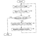
- FIG. 2 is a flowchart showing a turbine blade dehydrogenation processing method according to an embodiment.
- the turbine blade 10 is heated when the steam turbine 1 is stopped as one embodiment.
- the turbine blade 10 is heated when the steam turbine 1 is started. May be.
- the heating steam supplied into the casing 2 of the steam turbine 1 may be at a higher temperature than the steam (working steam) passing through the turbine blade 10 during operation of the steam turbine 1. More specifically, the heating steam may have a temperature higher than the temperature of the working steam at the site to which the heating steam is supplied.
- the heating steam supplied into the casing 2 of the steam turbine 1 is not particularly limited.
- ground steam described later may be used, or any steam generated in a plant in which the steam turbine 1 is provided.
- the optional steam include steam extracted from the auxiliary steam system of the plant, steam extracted from an intermediate pressure turbine, a high pressure turbine, and the like.
- the heating time of the turbine blade 10 that is, the time for supplying the heating steam into the vehicle interior 3 may be longer than the case where the dehydrogenation processing of the turbine blade 10 is not performed.
- the heating time of the turbine blade 10 may be set based on at least one of the hydrogen concentration contained in the turbine blade 10, the thickness of the turbine blade 10, the temperature of the heating steam, or the flow rate.
- the heating time of the turbine blade 10 may be 12 hours or more and within 24 hours.
- the steam temperature at each position in the passenger compartment 2 is generally determined. For this reason, depending on the position in the casing 2, the steam acting on the turbine blade 10 is relatively low temperature, and it is not possible to expect the release of hydrogen from the turbine blade 10 during operation of the steam turbine 1.
- the heating steam since the heating steam is supplied into the passenger compartment 2 when the steam turbine 1 is started or stopped, unlike the operation of the steam turbine 1, the heating steam having a temperature suitable for the dehydrogenation process. Can be used. Therefore, even for the turbine blade 10 that cannot be expected to be dehydrogenated during the operation of the steam turbine 1, the dehydrogenation process can be performed by bringing it into contact with the heated steam when the steam turbine 1 is started or stopped.
- the moving blade 8 can effectively remove hydrogen from the moving blade 8 by the above method due to the property that hydrogen is easily occluded during manufacture.
- hydrogen embrittlement of the turbine blade 10 can be suppressed without performing a complicated operation such as a removal operation of the turbine blade 10.
- heated steam having a temperature higher than that of the working steam the temperature of the turbine blade 10 can be easily increased, and dehydrogenation of the turbine blade 10 can be promoted.
- the turbine blade 10 in the step of heating the turbine blade 10 (S4), the turbine blade 10 may be heated to a temperature of 120 ° C. or higher (see FIGS. 3 to 5).
- a temperature of 120 ° C. or higher see FIGS. 3 to 5.
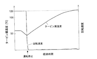
- FIG. 3 is a graph showing an example of changes over time in the turbine blade temperature and the rotational speed of the steam turbine.
- the hydrogen content in the turbine blade 10 is significantly reduced by heating the turbine blade 10 to a temperature of 120 ° C. or higher. Therefore, according to the said method, the dehydrogenation process of the turbine blade 10 can be effectively performed by heating up the turbine blade 10 to 120 degreeC or more.
- the heating steam may be supplied so that the temperature of the turbine blade 10 is 180 ° C. or less.
- the process of supplying the heating steam into the passenger compartment 3 may be repeated a plurality of times.
- the process of supplying the heated steam into the passenger compartment 2 is repeatedly performed when the steam turbine 1 is started or stopped until the cumulative number of times of heat treatment (S4) of the turbine blade 10 reaches the specified number. Also good.
- the cumulative number of executions of the heat treatment (S ⁇ b> 4) of the turbine blade 10 from the initial state of the steam turbine 1 has reached the specified number. It is determined whether or not (S3).
- the heat treatment (S4) of the turbine blade 10 is not performed.
- heating steam is supplied into the passenger compartment 2 to heat the turbine blades 10 (S4).
- the vacuum break or the supply of heated steam is stopped (S5). Thereafter, the operation of the steam turbine 1 is restarted as appropriate (S1), and when the steam turbine 1 is stopped (S2), it is determined again whether or not the cumulative number of times of heat treatment of the turbine blades 10 has reached the specified number. (S3). These steps are continued until the cumulative number of times of heat treatment of the turbine blade 10 reaches a specified number.
- the “specified number” is typically two or more times, and may be set individually according to, for example, the type of steam turbine, the ground steam temperature, and the like.
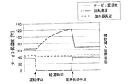
- FIG. 4 is a graph showing changes over time in the turbine blade temperature, the rotational speed of the steam turbine, and the casing vacuum according to an embodiment (when supply of heated steam is stopped).
- FIG. 5 is a graph showing changes over time in the turbine blade temperature, the rotation speed of the steam turbine, and the degree of vacuum in the passenger compartment (when vacuum breaks) according to another embodiment.
- the heating steam is supplied into the passenger compartment 2, and the supply of the heating steam is stopped after a predetermined time has elapsed.
- the turbine blade temperature gradually increases, and when the supply of the heating steam is stopped, the turbine blade temperature decreases.
- FIG. 4 shows changes over time in the turbine blade temperature, the rotational speed of the steam turbine, and the casing vacuum according to an embodiment (when supply of heated steam is stopped).
- FIG. 5 is a graph showing changes over time in the turbine blade temperature, the rotation speed of the steam turbine, and the degree of vacuum in the passenger compartment (when vacuum breaks) according to another embodiment.
- the vacuum break is an operation of opening the vacuum break valve of the condenser and bringing the pressure in the passenger compartment 2 close to the atmospheric pressure when a condenser (not shown) is provided at the rear stage of the steam turbine 1.
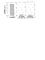
- FIG. 6 shows the hydrogen concentration when stainless steel in which 4.3 ppm of hydrogen is occluded is heated to over 120 ° C. As shown in the graph, when the heat treatment was performed only once, the hydrogen concentration decreased to 0.24 ppm, and when the heat treatment was repeated five times, the hydrogen concentration decreased to 0.03 ppm.
- the dehydrogenation process of the turbine blade 10 can be effectively performed by repeating the heat processing of the turbine blade 10 several times. Moreover, the dehydrogenation process of the turbine blade 10 can be effectively performed by repeating until the cumulative number of times the heat treatment of the turbine blade 10 reaches the specified number. In addition, when the hydrogen concentration of the turbine blade 10 in an initial state is low, or when the thickness of the turbine blade 10 is relatively thin, the number of heat treatments may be small.
- the turbine blade 10 to be heated may include the final stage blade (for example, the final stage moving blade 8a shown in FIG. 1) of the low-pressure steam turbine.
- the last stage blade of the low-pressure steam turbine is hardly expected to release hydrogen from the turbine blade 10 during operation of the steam turbine 1 because steam at a low temperature of, for example, about 50 ° C. acts during operation of the steam turbine 1.
- the heating steam is supplied into the passenger compartment 2 to perform complicated operations such as the removal operation of the turbine blades 10.
- hydrogen embrittlement of the last stage blade of the low-pressure steam turbine can be suppressed.
- the turbine blade 10 may be martensitic stainless steel.
- martensitic stainless steel examples include PH13-8Mo steel, 17-4PH steel, 12Cr steel, and the like.
- martensitic stainless steel used as a material for the turbine blade 10 is likely to be embrittled when the hydrogen content is increased.
- the steam turbine 1 when the steam turbine 1 is started or stopped, the heated steam is supplied into the vehicle compartment, so that the martensitic stainless steel is made without performing complicated operations such as the operation of removing the turbine blades 10. Damage due to hydrogen embrittlement of the turbine blade 10 can be prevented.
- ground steam as heated steam is passed through the ground seal portions 22a and 22b of the steam turbine 1 into the vehicle compartment 2. You may supply.
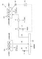
- FIG. 7 is a diagram illustrating a schematic configuration of a ground system (during high load operation) 20 according to an embodiment.
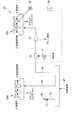
- FIG. 8 is a diagram illustrating a schematic configuration of a ground system (at the time of turbine blade heating) 20 according to an embodiment.
- each part of the steam turbine 1 will be described with reference numerals appropriately shown in FIG.
- the ground system 20 stores the ground seal portions 22a and 22b and the ground vapor supplied to the ground seal portions 22a and 22b.
- the ground steam refers to steam having an action of ensuring a sealing property between the vehicle interior space 3 and the vehicle exterior 4 by flowing through the ground seal portions 22a and 22b. That is, the ground steam includes steam flowing from the vehicle interior space 3 toward the exterior 4 through the ground seal portions 22a and 22b.
- the ground steam header 24 is configured to store the ground steam supplied to the ground seal portions 22a and 22b.
- the ground steam stored in the ground steam header 24 may be steam extracted from an auxiliary steam system of the plant, steam extracted from an intermediate pressure turbine, a high pressure turbine, or the like, or a turbine inlet Steam obtained by reducing the pressure of the steam may be used.
- the ground steam may include steam collected from the high-pressure side ground seal portion 22a at the time of high load.
- the ground steam may be a mixture of a plurality of kinds of steam having different generation sources as described above.
- the high-pressure side ground seal portion 22 a has steam (gland) from the vehicle interior space 3 toward the vehicle interior outside 4. Steam) flows out. At least a part of the ground steam is collected in the ground steam header 24 via the ground steam line 28. Further, at least a part of the ground steam may be led to a ground condenser to be condensed. For example, a part of the discharged ground vapor is collected from the vehicle compartment side portion X of the high-pressure side ground seal portion 22a to the ground steam header 24, and the remaining portion of the discharged ground vapor is guided from the atmosphere side portion Y to the ground condenser.
- ground steam is supplied from the ground steam header 24 to the low-pressure side ground seal portion 22b. Further, at least a part of the ground vapor flowing out from the low-pressure side ground seal portion 22b may be guided to the ground capacitor.
- the ground steam is supplied from the ground steam header 24 to the vehicle compartment side portion X of the low-pressure side ground seal portion 22b, and a part (including air) of the supplied ground steam is the atmosphere side of the low-pressure side ground seal portion 22b. It is led from the part Y to the ground capacitor.
- the ground steam is also supplied from the ground steam header 24 to the high-pressure side ground seal portion 22a.
- the ground steam from the ground steam header 24 is supplied to the ground seal portions 22 a and 22 b via the ground steam lines 28 and 29.
- the ground vapor is supplied into the vehicle interior 2 via the ground seal portions 22a and 22b.
- the ground steam is supplied from the ground steam header 24 to the vehicle compartment side portion X of the high pressure side ground seal portion 22a and the vehicle compartment side portion X of the low pressure side ground seal portion 22b. Further, part of the supplied ground vapor (including air) is led to the ground condenser from the atmosphere side portion Y of the high pressure side ground seal portion 22a and the atmosphere side portion Y of the low pressure side ground seal portion 22b.
- a discharge line 25 having a relief valve 26 may be connected to the ground steam header 24 for the purpose of preventing an excessive pressure rise in the ground steam header 24.
- the relief valve 26 is opened and the ground steam is discharged from the discharge line 25.
- the temperature of the ground steam may be set higher than that during the operation of the steam turbine 1. That is, the temperature of the ground steam when the turbine blade 10 is heat-treated is set higher than the temperature supplied to the ground seal portions 22 a and 22 b during the operation of the steam turbine 1.
- the steam supplied to the ground steam header 24 may be steam having a temperature higher than that during the operation of the steam turbine 1 or until the steam is supplied from the ground steam header 24 to the ground seal portions 22a and 22b as described later.
- the ground steam may be heated between.
- the turbine blade 10 can be heated to a higher temperature, and the dehydrogenation processing of the turbine blade 10 is effective. Can be done.
- the temperature controller is a superheat reducer (Deseater Heater) 30 provided in the ground steam line 29 between the ground steam header 24 and the ground seal portions 22a and 22b.
- the temperature reduction amount of the ground steam may be adjusted by the reducer 30.
- the overheat reducer 30 may cool the ground steam by indirectly exchanging heat with the ground water.
- the temperature of the turbine blade 10 is detected by the temperature sensor 36, and based on this temperature, the opening degree of the flow control valve 31 is controlled by the controller 35, and the flow rate of the cooling water for cooling the ground steam is adjusted. May be.
- the temperature controller may be a heater for heating the ground steam.
- the temperature of the turbine blade 10 during the dehydrogenation process is controlled by adjusting the temperature of the ground steam supplied to the ground seal portions 22a and 22b by the temperature controller provided in the ground steam line 29. And dehydrogenation treatment can be performed effectively. Further, an excessive increase in the temperature of the ground steam can be suppressed, and for example, an interlock operation related to the ground steam temperature can be prevented. Further, by using the overheat reducer 30 as a temperature adjuster, the temperature of the ground steam from the ground steam header 24 toward the ground seal portions 22a and 22b can be appropriately adjusted by the overheat reducer 30, so that dehydrogenation treatment is performed. And the prevention of the interlock operation related to the ground steam temperature can be achieved.
- the temperature setting value of the ground steam in the superheat reducer 30 may be made higher than that during the operation of the steam turbine 1. According to this, by setting the temperature setting value of the ground steam in the superheat reducer 30 to be higher than that during the operation of the steam turbine 1, the turbine blade 10 can be heated to a higher temperature, and the dehydrogenation process can be performed. Can be done effectively.
- a drain separator 32 may be provided on the ground steam line 29 on the low-pressure side ground seal portion 22 b side than the superheat reducer 30.
- the drain separator 32 is configured to separate the drain generated by the condensation of part of the ground vapor in the superheat reducer 30. In this way, the drain that is generated by condensing part of the ground vapor in the overheat reducer 30 is separated by the drain separator 32, thereby preventing the drain from flowing into the passenger compartment 2.
- the ground steam line 28 that supplies the ground steam to the high-pressure side ground seal portion 22a may be provided with the overheat reducer 30 and the drain separator 32.
- the ground steam is supplied to the ground seal portions 22a and 22b while maintaining the pressure in the passenger compartment 2 below atmospheric pressure, so that the ground steam flows into the passenger compartment 2 and the turbine blades.
- the pressure in the passenger compartment 2 may be increased to atmospheric pressure, or the supply of ground steam to the ground seal portions 22 a and 22 b may be stopped (see FIG. 5).
- the ground steam can be easily introduced into the passenger compartment 2 by supplying the ground steam to the ground seal portions 22a and 22b while maintaining the pressure in the passenger compartment 2 below atmospheric pressure. . Therefore, the cabin 2 can be filled with high-temperature ground steam, and the turbine blade 10 can be effectively heated by the ground steam.
- the turbine blade 10 that cannot be expected to be dehydrogenated during operation of the steam turbine 1 is also brought into contact with the heated steam when the steam turbine 1 is started or stopped.
- dehydrogenation treatment can be performed. Therefore, hydrogen embrittlement of the turbine blade 10 can be suppressed without performing a complicated operation such as a removal operation of the turbine blade 10.
- FIG. 1 shows a single flow type steam turbine in which the working steam flowing in from the passenger compartment entrance 2a flows in a single direction (the direction from the left to the right in the figure).
- the contents described above can also be applied to a double-flow type steam turbine in which working steam flowing in from the passenger compartment inlet flows on both sides.
- an expression indicating that things such as “identical”, “equal”, and “homogeneous” are in an equal state not only represents an exactly equal state, but also has a tolerance or a difference that can provide the same function. It also represents the existing state.
- the expression “comprising”, “including”, or “having” one constituent element is not an exclusive expression for excluding the existence of another constituent element.
Landscapes
- Engineering & Computer Science (AREA)
- Chemical & Material Sciences (AREA)
- Mechanical Engineering (AREA)
- General Engineering & Computer Science (AREA)
- Thermal Sciences (AREA)
- Physics & Mathematics (AREA)
- Crystallography & Structural Chemistry (AREA)
- Materials Engineering (AREA)
- Metallurgy (AREA)
- Organic Chemistry (AREA)
- Combustion & Propulsion (AREA)
- Turbine Rotor Nozzle Sealing (AREA)
- Heat Treatment Of Articles (AREA)
- Control Of Turbines (AREA)
Abstract
Description
このようなタービン翼では、加工時のプロセスにより鋼材中に水素が吸蔵される可能性がある。タービン翼として用いられる鋼材中に水素が吸蔵された場合、水素の影響によりタービン翼の脆化を招くおそれがある。
しかしながら、蒸気タービンの最終段付近の大型のタービン翼を熱処理する場合、熱処理装置が大型化し、また一度に処理できるタービン翼の本数が限られているために熱処理に多大な時間を要するといった問題がある。
そのため、煩雑な作業を行うことなく、タービン翼の水素脆化を抑制し得る方法が求められている。
蒸気タービンプラントの起動時又は停止時において、前記蒸気タービンの車室内に加熱蒸気を供給し、前記タービン翼を加熱するステップ
を備える。
上記(1)の方法によれば、蒸気タービンプラントの起動時又は停止時に車室内に加熱蒸気を供給するようにしたので、蒸気タービンプラントの運転中とは異なり、脱水素処理に適した温度の加熱蒸気を用いることができる。よって、蒸気タービンプラントの運転中に脱水素を期待できないタービン翼についても、蒸気タービンプラントの起動時又は停止時に加熱蒸気と接触させることで脱水素処理を行うことができる。
こうして、タービン翼の取り外し作業等の煩雑な作業を行うことなく、タービン翼の水素脆化を抑制することができる。
前記加熱蒸気は、前記蒸気タービンの運転中における前記タービン翼を通過する蒸気(作動蒸気)よりも高温である。
ここで、車室内に複数段のタービン翼が設けられている場合、最終段(最も低圧側の段)を含む1以上の段におけるタービン翼を脱水素対象(加熱対象)とし、加熱対象段のタービン翼の位置における作動蒸気温度よりも加熱蒸気の温度を高く設定してもよい。なお、この場合、加熱対象段よりも上流側の段を通過する作動蒸気の温度よりも加熱蒸気温度が低くてもよい。
前記タービン翼を加熱するステップでは、前記蒸気タービンのグランドシール部を介して、前記加熱蒸気としてのグランド蒸気を前記車室内に供給する。
上記(3)の方法によれば、典型的な蒸気タービン設備が有するグランドシール部及びグランド蒸気系統を利用することで、車室内の圧力が低くなる蒸気タービンプラントの起動時又は停止時において、グランドシール部を介してグランド蒸気(加熱蒸気)を車室内に容易に導入することができる。よって、加熱蒸気を車室内に供給するための特別な設備を設けることなく、タービン翼の脱水素処理を行うことができる。
前記タービン翼を加熱するステップでは、前記蒸気タービンの運転中に比べて前記グランド蒸気の温度を高く設定する。
前記グランド蒸気を前記グランドシール部に供給するためのグランド蒸気ラインに設けられた温度調節器により、前記グランド蒸気の温度を調節する。
前記温度調節器は、グランド蒸気ヘッダと前記グランドシール部との間において前記グランド蒸気ラインに設けられた過熱低減器(Desuper Heater)であり、
前記過熱低減器により、前記グランド蒸気の減温量を調節する。
前記タービン翼を加熱するステップでは、前記蒸気タービンの運転中に比べて、前記過熱低減器における前記グランド蒸気の温度設定値を高くする。
前記車室内の圧力を大気圧未満に維持しながら、前記グランドシール部に前記グランド蒸気を供給することで、前記車室内に前記グランド蒸気を流入させるとともに、
前記タービン翼の加熱後、前記車室内の前記圧力を大気圧まで上昇させる、または、前記グランドシール部への前記グランド蒸気の供給を停止する。
前記タービン翼を加熱するステップでは、前記タービン翼を120℃以上の温度まで加熱する。
よって、上記(9)の方法によれば、タービン翼を120℃以上まで昇温させることで、タービン翼の脱水素処理を効果的に行うことができる。
前記加熱蒸気を前記車室内に供給する処理を複数回繰り返す。
上記(10)の方法によれば、タービン翼の加熱処理を複数回繰り返すことで、タービン翼の脱水素処理を効果的に行うことができる。
前記処理の累積実施回数が規定回数に達するまで、前記蒸気タービンプラントの起動時又は停止時に、前記加熱蒸気を前記車室内に供給する前記処理を繰り返し行う。
なお、「規定回数」は、典型的には2回以上であり、例えば、蒸気タービンの種類、グランド蒸気温度等に応じて個別に設定されてもよい。
加熱対象の前記タービン翼は、低圧蒸気タービンの最終段翼を含む。
この点、上記(12)の方法によれば、上記(1)で述べたように、蒸気タービンプラントの起動時又は停止時に加熱蒸気を車室内に供給することで、タービン翼の取り外し作業等の煩雑な作業を行うことなく、低圧タービンの最終段翼の水素脆化を抑制することができる。
前記タービン翼は、マルテンサイト系ステンレス鋼である。
この点、上記(13)の方法によれば、上記(1)で述べたように、蒸気タービンプラントの起動時又は停止時に加熱蒸気を車室内に供給することで、タービン翼の取り外し作業等の煩雑な作業を行うことなく、マルテンサイト系ステンレス鋼のタービン翼の水素脆化に起因した損傷を防止することができる。
ロータ5は、軸受7a,7bによって、軸線Oを中心に回転自在に支持されている。
複数の動翼8は、ロータ5の周方向に配列されるように、タービンディスク6を介してロータ5に取り付けられている。これら複数の動翼8は、ロータ5の軸方向に複数段設けられて動翼列を形成している。
複数の静翼9は、車室2の周方向に配列されるように、車室2の内壁面に取り付けられている。これら複数の静翼9は、ロータ5の軸方向において動翼列と交互に複数段設けられて静翼列を形成している。
なお、蒸気タービン1の車室出口2bは復水器(不図示)に連通していてもよい。
この際、グランドシール部22a,22bには、グランド蒸気が供給される。これにより、車室2とロータ5との間の隙間のシール性を確保し、車室内空間3から車室外4へ蒸気が漏出すること、または、車室外4から車室内空間3に空気が侵入することを抑制するようになっている。
なお、図2に示す実施形態では、一実施形態として蒸気タービン1の停止時にタービン翼10を加熱する場合について示しているが、他の実施形態として蒸気タービン1の起動時にタービン翼10を加熱してもよい。
例えば、図2に示す実施形態では、蒸気タービン1を運転し(S1)、その後蒸気タービン1を停止する(S2)。そして、蒸気タービン1の停止後、蒸気タービン1の車室2内に加熱蒸気を供給し、タービン翼10を加熱する(S4)。
また、タービン翼10の加熱時間、すなわち加熱蒸気を車室3内に供給する時間は、タービン翼10の脱水素処理を行わない場合よりも長くてもよい。具体的には、タービン翼10の加熱時間は、タービン翼10に含有される水素濃度、タービン翼10の厚さ、加熱蒸気の温度又は流量の少なくとも一つに基づいて設定されてもよい。例えば、タービン翼10の加熱時間は、12時間以上且つ24時間以内であってもよい。
上記方法によれば、蒸気タービン1の起動時又は停止時に車室2内に加熱蒸気を供給するようにしたので、蒸気タービン1の運転中とは異なり、脱水素処理に適した温度の加熱蒸気を用いることができる。よって、蒸気タービン1の運転中に脱水素を期待できないタービン翼10についても、蒸気タービン1の起動時又は停止時に加熱蒸気と接触させることで脱水素処理を行うことができる。特に、動翼8は、製作時において水素が吸蔵されやすい性質上、上記方法によって効果的に動翼8から水素を除去することができる。
こうして、タービン翼10の取り外し作業等の煩雑な作業を行うことなく、タービン翼10の水素脆化を抑制することができる。
また、作動蒸気よりも高温の加熱蒸気を用いることによって、タービン翼10を高温化しやすくなり、タービン翼10の脱水素を促進することができる。
例えば、図3に示すように、蒸気タービン1への蒸気供給を停止すると、蒸気タービン1の回転速度は急激に低下し、その後車室2に加熱蒸気を供給すると、タービン翼温度は停止から時間が経過するにつれて徐々に上昇する。なお、図3は、タービン翼温度および蒸気タービンの回転速度の経時変化の一例を示すグラフである。
よって、上記方法によれば、タービン翼10を120℃以上まで昇温させることで、タービン翼10の脱水素処理を効果的に行うことができる。
なお、タービン翼10およびその他の車室内部材の耐熱性の観点から、タービン翼10の温度が180℃以下となるように加熱蒸気を供給してもよい。
この場合、タービン翼10の加熱処理(S4)の累積実施回数が規定回数に達するまで、蒸気タービン1の起動時又は停止時に、加熱蒸気を車室2内に供給する処理を繰り返し行うようにしてもよい。
その後、適宜蒸気タービン1の運転を再開し(S1)、蒸気タービン1を停止(S2)する際には、再度タービン翼10の加熱処理の累積実施回数が規定回数に達しているか否かを判断する(S3)。これらのステップを、タービン翼10の加熱処理の累積実施回数が規定回数に達するまで続ける。
なお、「規定回数」は、典型的には2回以上であり、例えば、蒸気タービンの種類、グランド蒸気温度等に応じて個別に設定されてもよい。
図4に示す実施形態では、蒸気タービン1の運転停止後、車室2内に加熱蒸気を供給し、所定時間経過したら加熱蒸気の供給を停止している。車室2内に加熱蒸気を供給することによって、タービン翼温度は徐々に上昇し、加熱蒸気の供給を停止したらタービン翼温度は低下する。
図5に示す実施形態では、蒸気タービン1の運転停止後、車室2内に加熱蒸気を供給し、所定時間経過したら真空破壊する。車室2内に加熱蒸気を供給することによって、タービン翼温度は徐々に上昇し、真空破壊後にタービン翼温度は低下する。この場合、真空破壊後に加熱蒸気の供給を停止してもよい。
なお、真空破壊とは、蒸気タービン1の後段に復水器(不図示)が設けられている場合に、復水器の真空破壊弁を開いて車室2内の圧力を大気圧力に近づける作業を言う。
ここで、図6に、上述したタービン翼10の加熱処理による脱水素効果の評価試験を行った結果を示す。図6は、4.3ppmの水素を吸蔵させたステンレス鋼を120℃超まで加熱処理したときの水素濃度を示している。同グラフに示すように、加熱処理が1回のみの場合には水素濃度が0.24ppmまで低下し、加熱処理を5回繰り返した場合には、水素濃度が0.03ppmまで低下した。
上記方法によれば、タービン翼10の加熱処理を複数回繰り返すことで、タービン翼10の脱水素処理を効果的に行うことができる。
また、タービン翼10の加熱処理の累積実施回数が規定回数に達するまで繰り返すことで、タービン翼10の脱水素処理を効果的に行うことができる。
なお、初期状態におけるタービン翼10の水素濃度が低い場合やタービン翼10の厚さが比較的薄い場合などには、加熱処理の回数は少なくてもよい。
低圧蒸気タービンの最終段翼は、蒸気タービン1の運転中において例えば50℃程度の低温の蒸気が作用するため、蒸気タービン1の運転中にタービン翼10からの水素の放出を殆ど期待できない。
この点、上記方法によれば、上述したように、蒸気タービン1の起動時又は停止時に加熱蒸気を車室2内に供給することで、タービン翼10の取り外し作業等の煩雑な作業を行うことなく、低圧蒸気タービンの最終段翼の水素脆化を抑制することができる。
本発明者らの知見によれば、タービン翼10の材料として用いられるマルテンサイト系ステンレス鋼は、水素含有量が高くなると、脆化を起こしやすい。
この点、上述したように、蒸気タービン1の起動時又は停止時に加熱蒸気を車室内に供給することで、タービン翼10の取り外し作業等の煩雑な作業を行うことなく、マルテンサイト系ステンレス鋼のタービン翼10の水素脆化に起因した損傷を防止することができる。
なお、以下、蒸気タービン1の各部位については、適宜図1に示した符号を付して説明する。
なお、本実施形態において、グランド蒸気とは、グランドシール部22a,22bを流れることによって車室内空間3と車室外4との間のシール性を確保する作用を有する蒸気を言う。すなわち、グランド蒸気は、グランドシール部22a,22bを介して、車室内空間3から車室外4へ向けて流れる蒸気を含む。
なお、蒸気タービン1の低負荷運転時または無負荷運転時は、高圧側グランドシール部22aにもグランド蒸気ヘッダ24からグランド蒸気が供給される。
この場合、図8に示すように温度調節器が、グランド蒸気ヘッダ24とグランドシール部22a,22bとの間においてグランド蒸気ライン29に設けられた過熱低減器(Desuper Heater)30であって、過熱低減器30によりグランド蒸気の減温量を調節するようにしてもよい。例えば、過熱低減器30は、グランド蒸気を冷却水と間接的に熱交換することによって冷却してもよい。この場合、タービン翼10の温度を温度センサ36によって検出し、この温度に基づいて、制御装置35により流量調節弁31の開度を制御し、グランド蒸気を冷却するための冷却水の流量を調節してもよい。
なお、不図示の他の実施形態では、温度調節器が、グランド蒸気を加熱するためのヒータであってもよい。
また、温度調節器として過熱低減器30を用いることによって、グランド蒸気ヘッダ24からグランドシール部22a,22bに向かうグランド蒸気を過熱低減器30により温度を適切に調節することができるので、脱水素処理の促進とグランド蒸気温度に関するインターロック作動の防止とを両立することができる。
これによれば、過熱低減器30におけるグランド蒸気の温度設定値を蒸気タービン1の運転中に比べて高く設定することで、タービン翼10をより高い温度まで加熱することができ、脱水素処理を効果的に行うことができる。
ドレン分離器32は、過熱低減器30においてグランド蒸気の一部が凝縮して発生したドレンを分離するように構成される。
このように、過熱低減器30においてグランド蒸気の一部が凝縮して発生したドレンをドレン分離器32で分離することによって、車室2内にドレンが流入することを防げる。
例えば、図1には、車室入口2aから流入した作動蒸気が単一方向(図中、左から右に向かう方向)に流れるシングルフロー型の蒸気タービンを示したが、上述した実施形態で説明した内容は、車室入口から流入した作動蒸気が両側に流れるダブルフロー型の蒸気タービンにも適用可能である。
また、一の構成要素を「備える」、「含む」、又は、「有する」という表現は、他の構成要素の存在を除外する排他的な表現ではない。
2 車室
5 ロータ
8 動翼
9 静翼
10 タービン翼
20 グランドシステム
22a 高圧側グランドシール部
22b 低圧側グランドシール部
23a,23b グランドケース
24 グランド蒸気ヘッダ
28,29 グランド蒸気ライン
30 過熱低減器
31 流量調節弁
32 ドレン分離器
Claims (13)
- 蒸気タービンのタービン翼の脱水素処理方法であって、
蒸気タービンプラントの起動時又は停止時において、前記蒸気タービンの車室内に加熱蒸気を供給し、前記タービン翼を加熱するステップ
を備えることを特徴とするタービン翼の脱水素処理方法。 - 前記加熱蒸気は、前記蒸気タービンの運転中における前記タービン翼を通過する蒸気よりも高温であることを特徴とする請求項1に記載のタービン翼の脱水素処理方法。
- 前記タービン翼を加熱するステップでは、前記蒸気タービンのグランドシール部を介して、前記加熱蒸気としてのグランド蒸気を前記車室内に供給することを特徴とする請求項1又は2に記載のタービン翼の脱水素処理方法。
- 前記タービン翼を加熱するステップでは、前記蒸気タービンの運転中のグランド蒸気に比べて、前記加熱蒸気としての前記グランド蒸気の温度を高く設定することを特徴とする請求項3に記載のタービン翼の脱水素処理方法。
- 前記グランド蒸気を前記グランドシール部に供給するためのグランド蒸気ラインに設けられた温度調節器により、前記グランド蒸気の温度を調節することを特徴とする請求項3又は4に記載のタービン翼の脱水素処理方法。
- 前記温度調節器は、グランド蒸気ヘッダと前記グランドシール部との間において前記グランド蒸気ラインに設けられた過熱低減器であり、
前記過熱低減器により、前記グランド蒸気の減温量を調節することを特徴とする請求項5に記載のタービン翼の脱水素処理方法。 - 前記タービン翼を加熱するステップでは、前記蒸気タービンの運転中に比べて、前記過熱低減器における前記グランド蒸気の温度設定値を高くすることを特徴とする請求項6に記載のタービン翼の脱水素処理方法。
- 前記車室内の圧力を大気圧未満に維持しながら、前記グランドシール部に前記グランド蒸気を供給することで、前記車室内に前記グランド蒸気を流入させるとともに、
前記タービン翼の加熱後、前記車室内の前記圧力を大気圧まで上昇させる、または、前記グランドシール部への前記グランド蒸気の供給を停止することを特徴とする請求項3乃至7の何れか一項に記載のタービン翼の脱水素処理方法。 - 前記タービン翼を加熱するステップでは、前記タービン翼を120℃以上の温度まで加熱することを特徴とする請求項1乃至8の何れか一項に記載のタービン翼の脱水素処理方法。
- 前記加熱蒸気を前記車室内に供給する処理を複数回繰り返すことを特徴とする請求項1乃至9の何れか一項に記載のタービン翼の脱水素処理方法。
- 前記処理の累積実施回数が規定回数に達するまで、前記蒸気タービンプラントの起動時又は停止時に、前記加熱蒸気を前記車室内に供給する前記処理を繰り返し行うことを特徴とする請求項10に記載のタービン翼の脱水素処理方法。
- 加熱対象の前記タービン翼は、低圧蒸気タービンの最終段翼を含むことを特徴とする請求項1乃至11の何れか一項に記載のタービン翼の脱水素処理方法。
- 前記タービン翼は、マルテンサイト系ステンレス鋼であることを特徴とする請求項1乃至12の何れか一項に記載のタービン翼の脱水素処理方法。
Priority Applications (4)
| Application Number | Priority Date | Filing Date | Title |
|---|---|---|---|
| CN201780020228.9A CN108884723B (zh) | 2016-03-31 | 2017-03-06 | 涡轮叶片的脱氢处理方法 |
| US16/086,705 US11066715B2 (en) | 2016-03-31 | 2017-03-06 | Dehydrogenation processing method for turbine blades |
| DE112017001657.6T DE112017001657T5 (de) | 2016-03-31 | 2017-03-06 | Verfahren zum durchführen einer wasserstoffentziehung für turbinenschaufeln |
| KR1020187027445A KR102111228B1 (ko) | 2016-03-31 | 2017-03-06 | 터빈 날개의 탈수소 처리 방법 |
Applications Claiming Priority (2)
| Application Number | Priority Date | Filing Date | Title |
|---|---|---|---|
| JP2016-071719 | 2016-03-31 | ||
| JP2016071719A JP6656992B2 (ja) | 2016-03-31 | 2016-03-31 | タービン翼の脱水素処理方法 |
Publications (1)
| Publication Number | Publication Date |
|---|---|
| WO2017169537A1 true WO2017169537A1 (ja) | 2017-10-05 |
Family
ID=59964111
Family Applications (1)
| Application Number | Title | Priority Date | Filing Date |
|---|---|---|---|
| PCT/JP2017/008808 Ceased WO2017169537A1 (ja) | 2016-03-31 | 2017-03-06 | タービン翼の脱水素処理方法 |
Country Status (6)
| Country | Link |
|---|---|
| US (1) | US11066715B2 (ja) |
| JP (1) | JP6656992B2 (ja) |
| KR (1) | KR102111228B1 (ja) |
| CN (1) | CN108884723B (ja) |
| DE (1) | DE112017001657T5 (ja) |
| WO (1) | WO2017169537A1 (ja) |
Families Citing this family (2)
| Publication number | Priority date | Publication date | Assignee | Title |
|---|---|---|---|---|
| JP6941587B2 (ja) * | 2018-04-27 | 2021-09-29 | 三菱パワー株式会社 | コンバインドサイクルプラント及びその運転方法 |
| IT202100002348A1 (it) * | 2021-02-03 | 2022-08-03 | Nuovo Pignone Tecnologie Srl | Gland condenser skid systems by shell & plates technology |
Citations (6)
| Publication number | Priority date | Publication date | Assignee | Title |
|---|---|---|---|---|
| JPS5392009A (en) * | 1977-01-21 | 1978-08-12 | Toshiba Corp | Control method for warming-up of turbine rotor |
| JPS62159704A (ja) * | 1986-01-09 | 1987-07-15 | Mitsubishi Heavy Ind Ltd | 蒸気タ−ビンの暖機方法 |
| JPH02308903A (ja) * | 1989-05-22 | 1990-12-21 | Toshiba Corp | 蒸気タービンのプレウォーミング装置 |
| JPH06306550A (ja) * | 1993-04-28 | 1994-11-01 | Toshiba Corp | 耐熱鋼及びその熱処理方法 |
| JPH06306551A (ja) * | 1993-04-28 | 1994-11-01 | Nippon Steel Corp | 高強度マルテンサイトステンレス鋼とその製造方法 |
| JPH0987739A (ja) * | 1995-09-26 | 1997-03-31 | Suzuki Kinzoku Kogyo Kk | 連続走行式鋼線の脱水素熱処理方法 |
Family Cites Families (5)
| Publication number | Priority date | Publication date | Assignee | Title |
|---|---|---|---|---|
| JPH08121112A (ja) | 1994-10-31 | 1996-05-14 | Toshiba Corp | 一軸型複合サイクル発電設備 |
| JP4982507B2 (ja) * | 2009-01-09 | 2012-07-25 | 株式会社日立製作所 | タービングランドシール蒸気減温制御装置および蒸気タービン発電設備におけるプラント制御方法 |
| JP5479192B2 (ja) | 2010-04-07 | 2014-04-23 | 株式会社東芝 | 蒸気タービンプラント |
| JP5762222B2 (ja) | 2011-09-05 | 2015-08-12 | 三菱重工業株式会社 | 蒸気タービン設備 |
| DE102014221563A1 (de) | 2014-10-23 | 2016-04-28 | Siemens Aktiengesellschaft | Verfahren zur Verkürzung des Anfahrvorgangs einer Dampfturbine |
-
2016
- 2016-03-31 JP JP2016071719A patent/JP6656992B2/ja active Active
-
2017
- 2017-03-06 US US16/086,705 patent/US11066715B2/en active Active
- 2017-03-06 WO PCT/JP2017/008808 patent/WO2017169537A1/ja not_active Ceased
- 2017-03-06 DE DE112017001657.6T patent/DE112017001657T5/de active Pending
- 2017-03-06 KR KR1020187027445A patent/KR102111228B1/ko active Active
- 2017-03-06 CN CN201780020228.9A patent/CN108884723B/zh active Active
Patent Citations (6)
| Publication number | Priority date | Publication date | Assignee | Title |
|---|---|---|---|---|
| JPS5392009A (en) * | 1977-01-21 | 1978-08-12 | Toshiba Corp | Control method for warming-up of turbine rotor |
| JPS62159704A (ja) * | 1986-01-09 | 1987-07-15 | Mitsubishi Heavy Ind Ltd | 蒸気タ−ビンの暖機方法 |
| JPH02308903A (ja) * | 1989-05-22 | 1990-12-21 | Toshiba Corp | 蒸気タービンのプレウォーミング装置 |
| JPH06306550A (ja) * | 1993-04-28 | 1994-11-01 | Toshiba Corp | 耐熱鋼及びその熱処理方法 |
| JPH06306551A (ja) * | 1993-04-28 | 1994-11-01 | Nippon Steel Corp | 高強度マルテンサイトステンレス鋼とその製造方法 |
| JPH0987739A (ja) * | 1995-09-26 | 1997-03-31 | Suzuki Kinzoku Kogyo Kk | 連続走行式鋼線の脱水素熱処理方法 |
Also Published As
| Publication number | Publication date |
|---|---|
| DE112017001657T5 (de) | 2018-12-20 |
| CN108884723A (zh) | 2018-11-23 |
| JP2017180396A (ja) | 2017-10-05 |
| JP6656992B2 (ja) | 2020-03-04 |
| KR20180110683A (ko) | 2018-10-10 |
| US20190100817A1 (en) | 2019-04-04 |
| CN108884723B (zh) | 2021-04-09 |
| KR102111228B1 (ko) | 2020-05-14 |
| US11066715B2 (en) | 2021-07-20 |
Similar Documents
| Publication | Publication Date | Title |
|---|---|---|
| US8210801B2 (en) | Systems and methods of reducing heat loss from a gas turbine during shutdown | |
| JP6589211B2 (ja) | ガスタービン、及びその部品温度調節方法 | |
| CA2625464C (en) | Method for warming-up a steam turbine | |
| EP3112607B1 (en) | Gas turbine cool-down phase operation methods | |
| US10082089B2 (en) | Systems and methods to improve shut-down purge flow in a gas turbine system | |
| US11473445B2 (en) | Steam turbine plant and cooling method for same | |
| CN103282606A (zh) | 低压蒸汽轮机 | |
| RU2667816C2 (ru) | Компрессор с тепловым экраном и способы работы | |
| WO2017169537A1 (ja) | タービン翼の脱水素処理方法 | |
| US20180058335A1 (en) | Systems and methods to improve shut-down purge flow in a gas turbine system | |
| US10082090B2 (en) | Systems and methods to improve shut-down purge flow in a gas turbine system | |
| CN104204422B (zh) | 蒸汽轮机系统和用于起动蒸汽轮机的方法 | |
| JP2017532503A (ja) | 主制御装置として熱応力制御装置を備えるタービン制御ユニット | |
| JP6282757B2 (ja) | 蒸気タービンの冷却方法 | |
| US20160326965A1 (en) | Method for controlling the temperature of a gas turbine during a shutdown | |
| US20160333743A1 (en) | Gas turbine operation method and operation control device | |
| US10082091B2 (en) | Systems and methods to improve shut-down purge flow in a gas turbine system | |
| US12025014B2 (en) | Pit initiation evaluation system, and, pit initiation evaluation method | |
| US11719121B2 (en) | Steam turbine | |
| KR20180019219A (ko) | 터보 기계 냉각용 방법 | |
| CN104989467B (zh) | 汽轮机停机冷却控制方法 | |
| CN103089435B (zh) | 包括热回收蒸汽发生器的联合循环发电设备 | |
| CN106460566A (zh) | 用于启动蒸汽轮机系统的方法 | |
| US20090288415A1 (en) | Method for Warming-Up a Steam Turbine | |
| JP2008075526A (ja) | 低圧蒸気タービンシステムおよび制御方法 |
Legal Events
| Date | Code | Title | Description |
|---|---|---|---|
| ENP | Entry into the national phase |
Ref document number: 20187027445 Country of ref document: KR Kind code of ref document: A |
|
| WWE | Wipo information: entry into national phase |
Ref document number: 1020187027445 Country of ref document: KR |
|
| 121 | Ep: the epo has been informed by wipo that ep was designated in this application |
Ref document number: 17774082 Country of ref document: EP Kind code of ref document: A1 |
|
| 122 | Ep: pct application non-entry in european phase |
Ref document number: 17774082 Country of ref document: EP Kind code of ref document: A1 |