WO2017169534A1 - 導電性接着剤 - Google Patents
導電性接着剤 Download PDFInfo
- Publication number
- WO2017169534A1 WO2017169534A1 PCT/JP2017/008729 JP2017008729W WO2017169534A1 WO 2017169534 A1 WO2017169534 A1 WO 2017169534A1 JP 2017008729 W JP2017008729 W JP 2017008729W WO 2017169534 A1 WO2017169534 A1 WO 2017169534A1
- Authority
- WO
- WIPO (PCT)
- Prior art keywords
- silver fine
- fine particles
- conductive adhesive
- protective layer
- acid
- Prior art date
- Legal status (The legal status is an assumption and is not a legal conclusion. Google has not performed a legal analysis and makes no representation as to the accuracy of the status listed.)
- Ceased
Links
Classifications
-
- C—CHEMISTRY; METALLURGY
- C09—DYES; PAINTS; POLISHES; NATURAL RESINS; ADHESIVES; COMPOSITIONS NOT OTHERWISE PROVIDED FOR; APPLICATIONS OF MATERIALS NOT OTHERWISE PROVIDED FOR
- C09J—ADHESIVES; NON-MECHANICAL ASPECTS OF ADHESIVE PROCESSES IN GENERAL; ADHESIVE PROCESSES NOT PROVIDED FOR ELSEWHERE; USE OF MATERIALS AS ADHESIVES
- C09J9/00—Adhesives characterised by their physical nature or the effects produced, e.g. glue sticks
- C09J9/02—Electrically-conducting adhesives
-
- B—PERFORMING OPERATIONS; TRANSPORTING
- B22—CASTING; POWDER METALLURGY
- B22F—WORKING METALLIC POWDER; MANUFACTURE OF ARTICLES FROM METALLIC POWDER; MAKING METALLIC POWDER; APPARATUS OR DEVICES SPECIALLY ADAPTED FOR METALLIC POWDER
- B22F1/00—Metallic powder; Treatment of metallic powder, e.g. to facilitate working or to improve properties
-
- B—PERFORMING OPERATIONS; TRANSPORTING
- B22—CASTING; POWDER METALLURGY
- B22F—WORKING METALLIC POWDER; MANUFACTURE OF ARTICLES FROM METALLIC POWDER; MAKING METALLIC POWDER; APPARATUS OR DEVICES SPECIALLY ADAPTED FOR METALLIC POWDER
- B22F1/00—Metallic powder; Treatment of metallic powder, e.g. to facilitate working or to improve properties
- B22F1/10—Metallic powder containing lubricating or binding agents; Metallic powder containing organic material
- B22F1/102—Metallic powder coated with organic material
-
- C—CHEMISTRY; METALLURGY
- C09—DYES; PAINTS; POLISHES; NATURAL RESINS; ADHESIVES; COMPOSITIONS NOT OTHERWISE PROVIDED FOR; APPLICATIONS OF MATERIALS NOT OTHERWISE PROVIDED FOR
- C09J—ADHESIVES; NON-MECHANICAL ASPECTS OF ADHESIVE PROCESSES IN GENERAL; ADHESIVE PROCESSES NOT PROVIDED FOR ELSEWHERE; USE OF MATERIALS AS ADHESIVES
- C09J1/00—Adhesives based on inorganic constituents
-
- H—ELECTRICITY
- H01—ELECTRIC ELEMENTS
- H01B—CABLES; CONDUCTORS; INSULATORS; SELECTION OF MATERIALS FOR THEIR CONDUCTIVE, INSULATING OR DIELECTRIC PROPERTIES
- H01B1/00—Conductors or conductive bodies characterised by the conductive materials; Selection of materials as conductors
-
- H—ELECTRICITY
- H01—ELECTRIC ELEMENTS
- H01B—CABLES; CONDUCTORS; INSULATORS; SELECTION OF MATERIALS FOR THEIR CONDUCTIVE, INSULATING OR DIELECTRIC PROPERTIES
- H01B1/00—Conductors or conductive bodies characterised by the conductive materials; Selection of materials as conductors
- H01B1/20—Conductive material dispersed in non-conductive organic material
- H01B1/22—Conductive material dispersed in non-conductive organic material the conductive material comprising metals or alloys
Definitions
- the present invention relates to a conductive adhesive, a method for producing the same, a sintered body of the conductive adhesive, and a circuit or an electrode including the sintered body between members.
- Conductive adhesives such as die bonds and die attach agents are bonding materials used for semiconductors, LEDs, power semiconductors and the like.
- a method it is generally known to join with a base material by joining by pressurization and heating or sintering by heating or the like without pressure.
- development of a non-pressurized bonding material has been advanced from the viewpoint of the simplicity and efficiency of the manufacturing process.
- Non-pressure bonding material is a conductive adhesive containing an epoxy resin.
- This bonding material is used by curing an epoxy resin by low-temperature treatment, and can suppress the generation of voids and improve the bonding strength with a base material (Patent Document 1).
- Patent Document 1 the epoxy resin itself becomes a resistor, the obtained conductivity is lowered.
- a bonding material that does not contain an epoxy resin a conductive adhesive made of only silver can be cited.
- This bonding material uses micro silver or sub-micron silver (particle diameter 300 to 900 nm) (Patent Document 2).
- silver nanoparticles have been developed, and silver nanoparticles are characterized by being easily sintered at a low temperature by a short heat treatment.
- silver nanoparticle having a particle diameter of about 20 nm it can be easily sintered at a relatively low temperature (200 ° C. or lower) to form a dense film.
- a relatively low temperature 200 ° C. or lower
- stress is generated in the coating film as the film thickness increases, resulting in cracks and chipping. For this reason, the development of a material that can suppress the generation of voids and has a low stress on the coating film is required.
- Patent Document 3 As a material that satisfies this requirement, a conductive adhesive containing nano-sized metal nanoparticles has been proposed (see, for example, Patent Document 3).
- the conductive adhesive containing nano-sized metal nanoparticles is placed between the members, and a sintered body heated and sintered at a high temperature (eg, 200 ° C. or higher) adheres between the members. High conductivity can be exhibited.
- a high temperature eg, 200 ° C. or higher
- the conventional sintered adhesive containing nano-sized silver fine particles causes cracking, chipping, etc. in the obtained sintered body, resulting in a decrease in mechanical strength. I found it.
- the heating time at the time of sintering is increased or the heating temperature is increased, the problem of cracking or chipping of the sintered body occurs remarkably.
- the main object of the present invention is to provide a conductive adhesive that is less susceptible to cracking or chipping due to sintering and that provides a sintered body having excellent mechanical strength. Furthermore, another object of the present invention is to provide a method for producing a conductive adhesive, a sintered body of a conductive adhesive, and a circuit or an electrode including the sintered body between members.
- the conductive adhesive has the first protective layer, the first silver fine particles A having an average particle diameter of 10 nm to 30 nm, the second protective layer containing hydroxy fatty acid, and the average particle
- the second silver fine particles B having a diameter of 50 nm to 100 nm are used, and the mass ratio (A: B) between the first silver fine particles A and the second silver fine particles B is 5:95 to 40
- a first silver fine particle A having a first protective layer and having an average particle diameter of 10 nm to 30 nm; Second silver fine particles B having a second protective layer and having an average particle diameter of 50 nm to 100 nm; Including The second protective layer comprises a hydroxy fatty acid; A conductive adhesive, wherein a mass ratio (A: B) between the first silver fine particles A and the second silver fine particles B is in a range of 5:95 to 40:60.
- Item 2. The conductive adhesive according to Item 1, wherein the first protective layer contains at least one of a fatty acid and an alkylamine.
- Item 4. Item 4. The conductive adhesive according to any one of Items 1 to 3, further comprising a solvent.
- Item 5. A first silver fine particle A having a first protective layer having an average particle diameter of 10 nm to 30 nm and a second protective layer containing a hydroxy fatty acid and having an average particle diameter of 50 nm to 100 nm.
- the silver fine particles B are mixed so that the mass ratio (A: B) of the first silver fine particles A and the second silver fine particles B is in the range of 5:95 to 40:60.
- the manufacturing method of a conductive adhesive provided with a process.
- Item 6. Item 5.
- Item 7. Item 7.
- a circuit or electrode comprising a portion where members are bonded by the sintered body according to Item 6.
- the manufacturing method of the said conductive adhesive, the sintered compact of the said conductive adhesive, and the circuit or electrode provided with the said sintered compact between members can be provided.
- the conductive adhesive of the present invention has a first protective layer having a first silver fine particle A having an average particle diameter of 10 nm to 30 nm and a second protective layer, and having an average particle diameter of 50 nm to A second silver fine particle B that is 100 nm, the second protective layer contains a hydroxy fatty acid, and a mass ratio (A: B) between the first silver fine particle A and the second silver fine particle B is It is in the range of 5:95 to 40:60.
- A: B mass ratio
- the conductive adhesive of the present invention is a generic term for the first silver fine particles A and the second silver fine particles B (hereinafter referred to as “first silver fine particles A and second silver fine particles B”). , Sometimes referred to as “silver fine particles”) at a predetermined ratio.
- the first silver fine particles A have a first protective layer on the surface layer of particles composed of silver (silver particles).
- a layer that can form a surface layer of silver particles and can function as a protective layer for example, a layer that suppresses aggregation of the first silver fine particles A and the second silver fine particles B
- fatty acids, alkylamines, hydroxy fatty acids and the like are preferable.
- the protective layer may be composed of one type of material, or may be composed of two or more types of materials.
- Fatty acids are not particularly limited, but preferably include fatty acids having 3 to 18 carbon atoms in the alkyl group, more preferably fatty acids having 4 to 18 carbon atoms in the alkyl group.
- Preferred examples of fatty acids include acetic acid, propionic acid, butyric acid, valeric acid, caproic acid, caprylic acid, 2-ethylhexanoic acid, capric acid, lauric acid, myristic acid, palmitic acid, stearic acid, oleic acid, linoleic acid , ⁇ -linolenic acid and the like.
- Specific examples of fatty acids include cyclic alkyl carboxylic acids such as cyclohexane carboxylic acid.
- caproic acid 2-ethylhexylic acid, oleic acid, linoleic acid, and ⁇ -linolenic acid are preferable from the viewpoint of effectively increasing the mechanical strength of the sintered body of the conductive adhesive.
- One type of fatty acid may be used alone, or two or more types may be used in combination.
- the alkylamine is not particularly limited, but preferably an alkylamine having 3 to 18 carbon atoms in the alkyl group, more preferably an alkylamine having 4 to 12 carbon atoms in the alkyl group.
- the alkyl in the first protective layer is used during sintering of the conductive adhesive. Since the amine is released from the surface of the silver fine particles A, the conductivity of the obtained sintered body is not substantially affected.
- alkylamine examples include ethylamine, n-propylamine, isopropylamine, 1,2-dimethylpropylamine, n-butylamine, isobutylamine, sec-butylamine, tert-butylamine, isoamylamine, tert-amylamine, 3 -Pentylamine, n-amylamine, n-hexylamine, n-heptylamine, n-octylamine, 2-octylamine, 2-ethylhexylamine, n-nonylamine, n-aminodecane, n-aminoundecane, n-dodecylamine , N-tridecylamine, 2-tridecylamine, n-tetradecylamine, n-pentadecylamine, n-hexadecylamine, n-heptadec
- secondary amines such as dibutylamine and cyclic alkylamines such as cyclopropylamine, cyclobutylamine, cyclopropylamine, cyclohexylamine, cycloheptylamine, and cyclooctylamine can be exemplified.
- the molar ratio of alkylamine to fatty acid is preferably about 90:10 to about 99.9: 0.1.
- Examples of the hydroxy fatty acid that can be contained in the first protective layer include the same hydroxy fatty acids as those contained in the second protective layer described later.
- the ratio (% by mass) of the first protective layer in the first silver fine particles A is not particularly limited, but the mechanical property of the sintered body of the conductive adhesive while protecting the surface of the first silver fine particles A is not limited. From the viewpoint of effectively increasing the strength, it is preferably about 0.1 to 10% by mass, more preferably about 1 to 8% by mass.
- the average particle diameter of the first silver fine particles A is in the range of 10 nm to 30 nm.
- the first silver fine particles A having such a specific particle diameter and the second silver fine particles A described later are used in combination at a specific blending ratio, whereby a sintered body of a conductive adhesive is used. It is possible to effectively increase the mechanical strength.
- the average particle diameter of the first silver fine particles A is preferably in the range of 15 to 25 nm.
- the average particle diameter of the first silver fine particles A is an average value of the lengths of the long sides of 30 or more particles included in an image observed with a scanning electron microscope.
- the average value of the long side lengths of any 30 or more particles included in the image can be used.
- the average particle diameter of the first silver fine particles A is determined for the conductive adhesive in which the first silver fine particles A and the second silver fine particles B described later are mixed, it is observed with a scanning electron microscope.
- 30 or more particles are selected in ascending order of the long side of the particles included in the image to be used, and the average value of the long side lengths of the 30 or more particles is selected.
- the second silver fine particles B have a second protective layer on the surface layer of particles composed of silver (silver particles).
- the second protective layer contains a hydroxy fatty acid.
- hydroxy fatty acid a compound having 3 to 24 carbon atoms and having one or more hydroxyl groups (for example, one) can be used.
- hydroxy fatty acids include 2-hydroxydecanoic acid, 2-hydroxydodecanoic acid, 2-hydroxytetradecanoic acid, 2-hydroxyhexadecanoic acid, 2-hydroxyoctadecanoic acid, 2-hydroxyeicosanoic acid, 2-hydroxydocosanoic acid, 2-hydroxytricosanoic acid, 2-hydroxytetracosanoic acid, 3-hydroxyhexanoic acid, 3-hydroxyoctanoic acid, 3-hydroxynonanoic acid, 3-hydroxydecanoic acid, 3-hydroxyundecanoic acid, 3-hydroxydodecanoic acid, 3-hydroxytridecanoic acid, 3-hydroxytetradecanoic acid, 3-hydroxyhexadecanoic acid, 3-hydroxyheptadecanoic acid, 3-hydroxyoctadecanoic acid, ⁇ -hydroxy-2-dece
- hydroxy fatty acids having 4 to 18 carbon atoms and having one hydroxyl group other than the ⁇ position (particularly the 12th position) are preferred, and ricinoleic acid and 12-hydroxystearic acid are more preferred.
- the hydroxy fatty acid contained in the second protective layer may be one type or two or more types.
- the second protective layer may further contain alkylamine, fatty acid and the like in addition to hydroxy fatty acid.
- alkylamine and a fatty acid the same thing as what was illustrated by the above-mentioned 1st protective layer can be illustrated.
- the molar ratio of alkylamine to hydroxy fatty acid is preferably about 90:10 to about 99.9: 0. In the range of about 95: 5 to about 99.8: 0.2.
- the ratio (% by mass) of the second protective layer in the second silver fine particles B is not particularly limited, but the mechanical property of the sintered body of the conductive adhesive while protecting the surface of the second silver fine particles B is not limited. From the viewpoint of effectively increasing the strength, it is preferably about 0.1 to 10% by mass, more preferably about 0.1 to 5% by mass.
- the average particle diameter of the second silver fine particles B is in the range of 50 nm to 100 nm. From the viewpoint of effectively increasing the mechanical strength of the sintered body of the conductive adhesive, the average particle diameter of the second silver fine particles B is preferably in the range of 65 nm to 90 nm.
- the average particle diameter of the second silver fine particles B is an average value of the lengths of the long sides of 30 or more particles included in an image observed with a scanning electron microscope.
- the average value of the long side lengths of arbitrary 30 or more particles included in the image can be used.
- the average particle diameter of the second silver fine particles B is determined for the conductive adhesive in which the second silver fine particles B and the first silver fine particles A are mixed, it is observed with a scanning electron microscope.
- 30 or more particles are selected in order from the longest side of the particles contained in the image to be used, and the average value of the lengths of the long sides of the 30 or more particles is selected.
- the mass ratio (A: B) between the first silver fine particles A and the second silver fine particles B is in the range of 5:95 to 40:60.
- the first silver fine particles A having a particle diameter in the predetermined range, and the second silver fine particles A having a particle diameter larger than that of the first silver fine particles A and having a specific protective layer By using together at such a mass ratio, it is possible to effectively increase the mechanical strength of the sintered body of the conductive adhesive.
- the details of this mechanism are not necessarily clear, but can be considered as follows, for example.
- the first silver fine particles A having a small average particle diameter fill the gaps between the second silver fine particles B, and the sintering proceeds in advance. Then, since the sintering of the second silver fine particles B having a large particle diameter protected with hydroxy fatty acid proceeds stably, cracking and chipping during the sintering are suppressed, resulting in excellent mechanical strength. It is considered that a sintered body can be obtained.
- the mass ratio of the first silver fine particles A to the second silver fine particles B is preferably about 10:90 to 40:60, about 20:80 to 40:60, about 5:95 to 30:70, about 10:90 to 30:70, 20:80 to 30: 70 or so.
- the total ratio of the first silver fine particles A and the second silver fine particles B is not particularly limited, but is preferably 80% by mass or more, more preferably 85% by mass to 95% by mass. %.
- the conductive adhesive of the present invention preferably further contains a solvent in addition to the first silver fine particles A and the second silver fine particles B.
- a solvent By containing a solvent, fluidity
- the solvent is not particularly limited as long as it can disperse the first silver fine particles A and the second silver fine particles B, but preferably contains a polar organic solvent.
- polar organic solvents include ketones such as acetone, acetylacetone and methyl ethyl ketone; ethers such as diethyl ether, dipropyl ether, dibutyl ether, tetrahydrofuran and 1,4-dioxane; 1,2-propanediol, 1,2-butane Diol, 1,3-butanediol, 1,4-butanediol, 2,3-butanediol, 1,2-hexanediol, 1,6-hexanediol, 1,2-pentanediol, 1,5-pentanediol Diols such as 2-methyl-2,4-pentanediol, 3-methyl-1,5-pentanediol, 1,2-oc
- a linear or branched alcohol having 3 to 5 carbon atoms, 3-methoxy-3-methyl-1- Butanol, 3-methoxy-1-butanol, diethylene glycol monobutyl ether, diethylene glycol monobutyl ether acetate, and terpineol are preferred.
- the solvent may further contain a nonpolar or hydrophobic solvent in addition to the polar organic solvent.
- Non-polar organic solvents include linear, branched, or cyclic saturated hydrocarbons such as hexane, heptane, octane, nonane, decane, 2-ethylhexane, and cyclohexane; linear or branched alcohols having 6 or more carbon atoms Alcohols such as benzene, toluene and benzonitrile; halogenated hydrocarbons such as dichloromethane, chloroform and dichloroethane; methyl-n-amyl ketone; methyl ethyl ketone oxime; and triacetin.
- saturated hydrocarbons and linear or branched alcohols having 6 or more carbon atoms are preferable, and hexane, octane, decane, octanol, decanol, and dodecanol are more preferable.
- a solvent can be used individually by 1 type or in mixture of 2 or more types.
- the ratio of the polar organic solvent is preferably 5% by volume or more, more preferably 10% by volume or more, and further preferably 15% by volume or more with respect to the total amount of the solvent. More preferred. Moreover, it can be 60 volume% or less, can also be 55 volume% or less, and can also be 50 volume% or less.
- the solvent may consist of only a polar organic solvent.
- the conductive adhesive of the present invention has good dispersibility of the first silver fine particles A and the second silver fine particles B even in the case of containing a large amount of polar organic solvent.
- the ratio of the solvent is not particularly limited, but is preferably 20% by mass or less, more preferably about 5% by mass to 15% by mass.
- an additive usually contained in the conductive adhesive may be added.
- the conductive adhesive of the present invention has a first protective layer, a first silver fine particle A having an average particle diameter of 10 nm to 30 nm, and a second protective containing a hydroxy fatty acid.
- a second silver fine particle B having a layer and an average particle diameter of 50 nm to 100 nm, and a mass ratio (A: B) between the first silver fine particle A and the second silver fine particle B of 5; : It can be easily produced by a method comprising a step of mixing so as to be in the range of 95 to 40:60.
- the details of the first silver fine particles A and the second silver fine particles B are as described in detail in the aforementioned “1.
- Conductive adhesive is as described in detail in the aforementioned “1.
- the mixing of the first silver fine particles A and the second silver fine particles B is performed by dispersing the first silver fine particles A and the second silver fine particles B. It is preferable to carry out by mixing the liquid.
- the average particle size of the first silver fine particles A is 10 nm to 30 nm
- the average particle size of the second silver fine particles B is 50 nm to 100 nm, and since both particles have nano-sized particle sizes, Unless mixed in a dispersed state, it is difficult to obtain a conductive adhesive in which these particles are uniformly dispersed.
- a solvent what was illustrated by the above-mentioned "1. conductive adhesive" is preferable.
- the method for producing the first silver fine particles A and the second silver fine particles B is not particularly limited, and each can be produced by a known method. Examples of these production methods include the method described in JP-A-2015-40319. An example of a method for producing the first silver fine particles A and the second silver fine particles B is shown below.
- a composition (a composition for preparing silver fine particles) for producing the first silver fine particles A or the second silver fine particles B is prepared.
- a silver compound (preferably silver oxalate or the like) that is a raw material of the silver fine particles and components constituting the first protective layer or the second protective layer (the above-described fatty acid, alkylamine, hydroxy fatty acid, etc.) And an organic solvent is prepared.
- these components are mixed to obtain a silver fine particle preparation composition. What is necessary is just to adjust suitably the ratio of each component in the said composition so that it may become the structure of the above-mentioned 1st silver fine particle A and 2nd silver fine particle B.
- the content of silver oxalate in the composition is preferably about 20 to 70% by mass relative to the total amount of the composition.
- the content of the fatty acid is preferably about 0.1% by mass to 20% by mass with respect to the total amount of the composition.
- the alkylamine content is preferably about 5% by mass to 55% by mass with respect to the total amount of the composition.
- the content of hydroxy fatty acid is preferably about 0.1% by mass to 15% by mass with respect to the total amount of the composition.
- the mixing means of each component is not particularly limited, and can be mixed by a general-purpose apparatus such as a mechanical stirrer, a magnetic stirrer, a vortex mixer, a planetary mill, a ball mill, a three roll, a line mixer, a planetary mixer, or a dissolver.
- a general-purpose apparatus such as a mechanical stirrer, a magnetic stirrer, a vortex mixer, a planetary mill, a ball mill, a three roll, a line mixer, a planetary mixer, or a dissolver.
- the temperature of the composition is, for example, 60 ° C. or less, particularly 40 ° C. It is preferable to mix while keeping below.
- the composition for preparing silver fine particles by subjecting the composition for preparing silver fine particles to a reaction in a reaction vessel, usually a reaction by heating, a thermal decomposition reaction of the silver compound occurs to produce silver fine particles.
- the composition may be introduced into a previously heated reaction vessel, or may be heated after the composition is introduced into the reaction vessel.
- the reaction temperature may be any temperature at which the thermal decomposition reaction proceeds and silver fine particles are generated, and it may be about 50 to 250 ° C., for example. Further, the reaction time may be appropriately selected according to the desired average particle size and the composition of the composition corresponding thereto. Examples of the reaction time include 1 minute to 100 hours.
- the silver fine particles produced by the thermal decomposition reaction are obtained as a mixture containing unreacted raw materials, it is preferable to purify the silver fine particles.
- the purification method include a solid-liquid separation method, a precipitation method using a specific gravity difference between silver fine particles and an unreacted raw material such as an organic solvent.
- the solid-liquid separation method include filter filtration, centrifugal separation, cyclone type, and decanter methods.
- the viscosity of the mixture may be adjusted by diluting a mixture containing silver fine particles with a low-boiling solvent such as acetone or methanol.
- the average particle diameter of the obtained silver fine particles can be adjusted.
- Sintered body of conductive adhesive The sintered body of the conductive adhesive of the present invention is obtained by sintering the conductive adhesive of the present invention described in detail in the above-mentioned "1. Conductive adhesive”. .
- the sintered body of the conductive adhesive of the present invention most of the components constituting the first protective layer and the second protective layer of the conductive adhesive are detached due to high heat during sintering.
- the sintered body is substantially composed of silver.
- the sintering temperature is not particularly limited, but is preferably about 150 ° C. to 200 ° C. from the viewpoint of effectively increasing the mechanical strength while the obtained sintered body exhibits high conductivity and high adhesive force.
- the temperature is about 150 ° C. to 185 ° C.
- the sintering time is preferably about 0.4 to 2.0 hours, more preferably about 0.5 to 1.2 hours.
- Sintering can be performed in an atmosphere such as air or an inert gas (nitrogen gas, argon gas).
- the sintering means is not particularly limited, and examples thereof include an oven, a hot air drying furnace, an infrared drying furnace, laser irradiation, flash lamp irradiation, and microwave.
- circuit or Electrode includes a portion where members are bonded by the sintered body of the present invention. That is, the circuit or electrode of the present invention is obtained by disposing the conductive adhesive of the present invention described in detail in “1. Conductive adhesive” between the members of the circuit or electrode, and sintering the conductive adhesive. And the members are bonded together.
- the sintered body of the present invention exhibits high electrical conductivity and high adhesive force, and the mechanical strength is effectively enhanced. Therefore, even in a circuit or an electrode including the sintered body, Excellent electrical conductivity and adhesion, and excellent mechanical strength.
- the mixture was stirred for 30 minutes in an oil bath at 0 ° C. After cooling, the magnetic stir bar was taken out, 1.5 g of methanol was added to each composition and stirred with a vortex mixer, and then for 1 minute at 3000 rpm (about 1600 ⁇ G) with a centrifuge (CF7D2 manufactured by Hitachi Koki). The supernatant was removed by tilting the centrifuge tube. The steps of adding 15 g of methanol, stirring, centrifuging, and removing the supernatant were repeated twice to recover the produced silver fine particles.
- these glass centrifuge tubes were set up on a hot stirrer (Hike-19G-U, manufactured by Koike Seimitsu Seisakusho) equipped with an aluminum block, and stirred for 30 minutes in a 40 ° C. hot water bath. The mixture was stirred for 30 minutes in an oil bath at 0 ° C. After standing to cool, the magnetic stir bar was taken out, 15 g of methanol was added to each composition, and the mixture was stirred with a vortex mixer, and then centrifuged at 3000 rpm (about 1600 ⁇ G) for 1 minute with a centrifuge (CF7D2 manufactured by Hitachi Koki). A sedimentation operation was performed, and the supernatant was removed by tilting the centrifuge tube. The steps of adding 15 g of methanol, stirring, centrifuging, and removing the supernatant were repeated twice to recover the produced silver fine particles.
- a hot stirrer Hike-19G-U, manufactured by Koike Seimitsu Seisakusho
- the mixture was stirred for 30 minutes in an oil bath at 0 ° C. After standing to cool, the magnetic stir bar was taken out, 15 g of methanol was added to each composition, and the mixture was stirred with a vortex mixer, and then centrifuged at 3000 rpm (about 1600 ⁇ G) for 1 minute with a centrifuge (CF7D2 manufactured by Hitachi Koki). A sedimentation operation was performed, and the supernatant was removed by tilting the centrifuge tube. The steps of adding 15 g of methanol, stirring, centrifuging, and removing the supernatant were repeated twice to recover the produced silver fine particles.
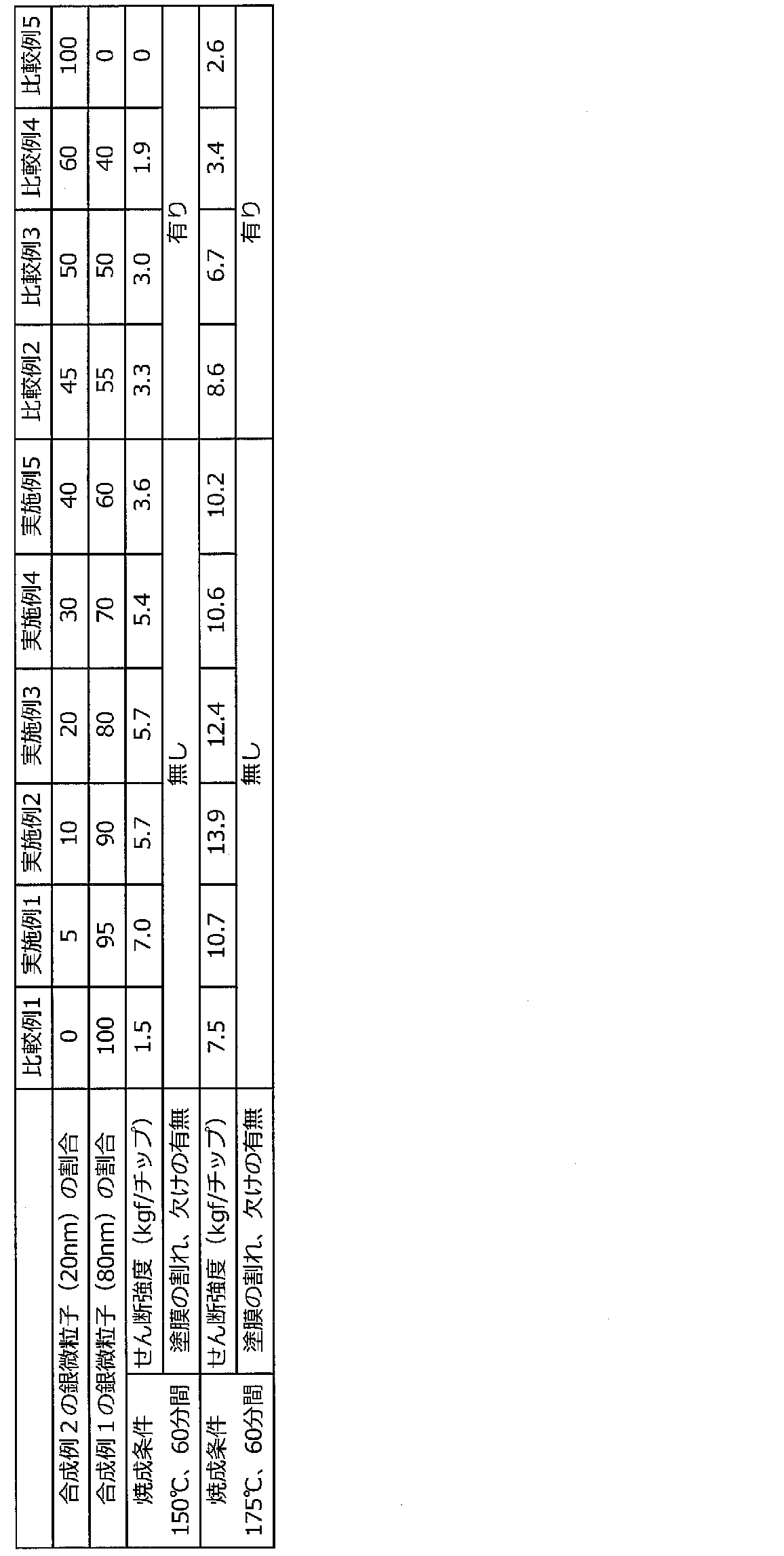
- Examples 1 to 5 and Comparative Examples 1 to 5 The silver fine particles obtained in Synthesis Example 1 and the silver fine particles obtained in Synthesis Example 2 were mixed at a predetermined ratio shown in Table 2, and terpineol corresponding to 10% of the total weight was added to obtain a dispersion. This solution was mixed twice in a stirring priority mode using a Mazerustar manufactured by Kurabo Industries, and each conductive adhesive was prepared.
- each conductive adhesive may have a film thickness of 50 micrometers
- a silicon wafer (size 2 mm ⁇ 2 mm) having a gold plating or gold sputtering process on the back surface (the surface in contact with the conductive adhesive) was placed on top. This was heated at a predetermined temperature (150 ° C., 175 ° C.) for 60 minutes with a dryer (circulation type) to obtain a coating film in which each conductive adhesive was sintered.
- each conductive adhesive may have a film thickness of 50 micrometers
- a silicon wafer (size 2 mm ⁇ 2 mm) having a gold plating or gold sputtering process on the back surface (the surface in contact with the conductive adhesive) was placed on top. This was heated with a dryer (circulation) at a predetermined temperature for 60 minutes to obtain a coating film in which each conductive adhesive was sintered.
- the obtained coating film was evaluated for mechanical strength and evaluation of cracking and chipping of the coating film in the same manner as in Examples 1 to 5 and Comparative Examples 1 to 5. The results are shown in Table 3.
- the shear strength of the coating film can be identified as any of the Examples, but there was a crack or chip in the coating film. It was. This is considered to be because stress is applied to the sintered film when the content of 20 nm particles increases.
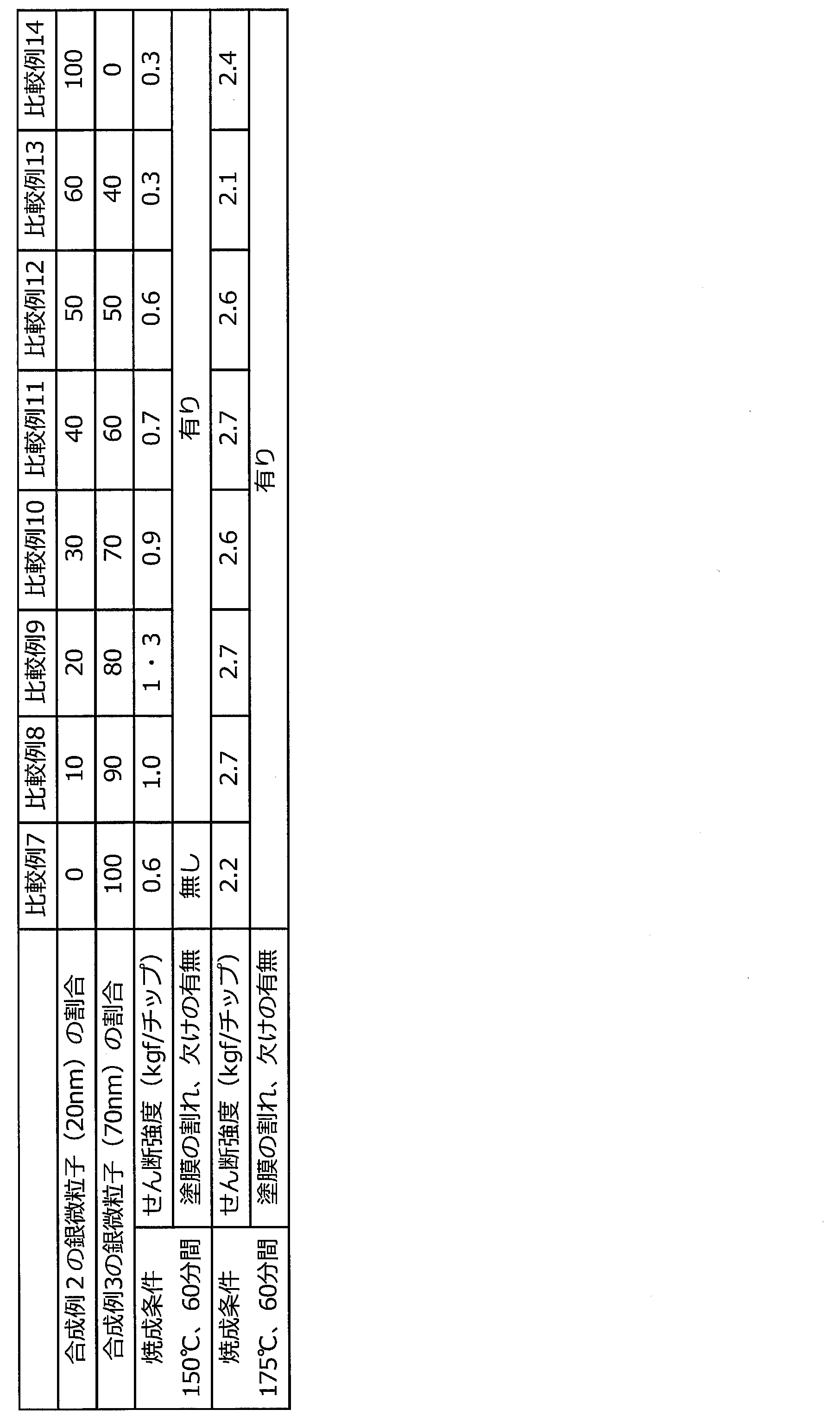
- silver fine particles (70 nm) using oleic acid in the protective layer and silver fine particles (80 nm) using ricinoleic acid in the protective layer are included in a mixing ratio of 70:30. Compared with 1 to 5, the shear strength of the coating film was low, and the coating film was cracked or chipped.
- each conductive adhesive may have a film thickness of 50 micrometers
- a silicon wafer (size 2 mm ⁇ 2 mm) having a gold plating or gold sputtering process on the back surface (the surface in contact with the conductive adhesive) was placed on top. This was heated at a predetermined temperature (150 ° C., 175 ° C.) for 60 minutes with a dryer (circulation type) to obtain a coating film in which each conductive adhesive was sintered.
- the obtained coating film was evaluated for mechanical strength and evaluation of cracking and chipping of the coating film in the same manner as in Examples 1 to 5 and Comparative Examples 1 to 5. The results are shown in Table 4.
Landscapes
- Chemical & Material Sciences (AREA)
- Organic Chemistry (AREA)
- Physics & Mathematics (AREA)
- Dispersion Chemistry (AREA)
- Spectroscopy & Molecular Physics (AREA)
- Inorganic Chemistry (AREA)
- Conductive Materials (AREA)
- Powder Metallurgy (AREA)
- Adhesives Or Adhesive Processes (AREA)
- Non-Insulated Conductors (AREA)
- Pigments, Carbon Blacks, Or Wood Stains (AREA)
- Manufacture Of Metal Powder And Suspensions Thereof (AREA)
Abstract
Description
項1. 第1の保護層を有し、平均粒子径が10nm~30nmである第1の銀微粒子Aと、
第2の保護層を有し、平均粒子径が50nm~100nmである第2の銀微粒子Bと、
を含み、
前記第2の保護層が、ヒドロキシ脂肪酸を含み、
前記第1の銀微粒子Aと、前記第2の銀微粒子Bとの質量比(A:B)が、5:95~40:60の範囲内にある、導電性接着剤。
項2. 前記第1の保護層が、脂肪酸及びアルキルアミンの少なくとも一方を含む、項1に記載の導電性接着剤。
項3. 前記第1の銀微粒子Aと前記第2の銀微粒子Bの合計割合が、80質量%以上である、項1または2に記載の導電性接着剤。
項4. 溶媒をさらに含む、項1~3のいずれかに記載の導電性接着剤。
項5. 第1の保護層を有し、平均粒子径が10nm~30nmである第1の銀微粒子Aと、ヒドロキシ脂肪酸を含む第2の保護層を有し、平均粒子径が50nm~100nmである第2の銀微粒子Bとを、前記第1の銀微粒子Aと、前記第2の銀微粒子Bとの質量比(A:B)が、5:95~40:60の範囲内となるように混合する工程を備える、導電性接着剤の製造方法。
項6. 項1~4のいずれかに記載の導電性接着剤の焼結体。
項7. 項6に記載の焼結体により部材間が接着された部分を備えている、回路または電極。
本発明の導電性接着剤は、前述の第1の銀微粒子A及び第2の銀微粒子B(以下、「第1の銀微粒子A及び第2の銀微粒子B」を総称して、「銀微粒子」ということがある)を所定の割合で含んでいる。
本発明の導電性接着剤は、第1の保護層を有し、平均粒子径が10nm~30nmである第1の銀微粒子Aと、ヒドロキシ脂肪酸を含む第2の保護層を有し、平均粒子径が50nm~100nmである第2の銀微粒子Bとを、前記第1の銀微粒子Aと、第2の銀微粒子Bとの質量比(A:B)が、5:95~40:60の範囲内となるように混合する工程を備える方法により、簡便に製造することができる。ここで、第1の銀微粒子A及び第2の銀微粒子Bの詳細については、前述の「1.導電性接着剤」において詳述した通りである。
本発明の導電性接着剤の焼結体は、前述の「1.導電性接着剤」で詳述した本発明の導電性接着剤を焼結することにより得られる。本発明の導電性接着剤の焼結体においては、導電性接着剤の第1の保護層及び第2の保護層を構成している成分が、焼結の際の高熱により、ほとんどが離脱しており、焼結体は、実質的に銀により構成されている。
本発明の回路または電極は、それぞれ、本発明の焼結体により部材間が接着された部分を備えている。すなわち、本発明の回路または電極は、前述の「1.導電性接着剤」で詳述した本発明の導電性接着剤を、回路または電極の部材間に配置し、導電性接着剤を焼結させて、部材間を接着したものである。
・シュウ酸銀((COOAg)2)特許文献1(特許第5574761号公報)に記載の方法で合成した。
・リシノール酸(東京化成工業株式会社製)
・オレイン酸(和光純薬工業株式会社製)
・N,N-ジメチル-1,3-ジアミノプロパン(和光純薬工業株式会社製)
・シクロヘキシルアミン(和光純薬工業株式会社製)
・n-ドデシルアミン(和光純薬工業株式会社製)
・n-ブチルアミン(和光純薬工業株式会社製)
・ブタノール(和光純薬工業株式会社製)
・n-オクチルアミン(和光純薬工業株式会社)
磁気撹拌子を入れた50mLガラス製遠沈管に、リシノール酸(0.03g)、N,N-ジメチル-1,3-ジアミノプロパン(2.6g)、及びブタノール(4.8g)を投入し、1分間程度攪拌したのち、シュウ酸銀(3.2g)を投入し、約10分間攪拌することで、銀微粒子調製用組成物を得た。その後、アルミブロックを備えたホットスターラー(小池精密機器製作所製HHE-19G-U)上に、これらのガラス製遠沈管を立てて設置し、40℃の湯浴で30分間攪拌し、さらに、90℃の油浴にて30分間攪拌した。放冷後、磁気撹拌子を取り出し、各組成物にメタノール1.5gを添加してボルテックスミキサーで攪拌した後、遠心分離機(日立工機製CF7D2)にて3000rpm(約1600×G)で1分間の遠沈操作を実施し、遠沈管を傾けることにより上澄みを除去した。メタノール15gの添加、撹拌、遠心分離、及び上澄み除去の工程を2回繰り返し、製造された銀微粒子を回収した。
磁気撹拌子を入れた50mLガラス製遠沈管に、オレイン酸(0.06g)、n-オクチルアミン(1.40g)、N,N-ジメチル-1,3-ジアミノプロパン(0.43g)、n-ドデシルアミン(0.16g)、シクロヘキシルアミン(0,12g)、n-ブチルアミン(0.64g)を投入し、1分間程度攪拌したのち、シュウ酸銀(3.2g)を投入し、約10分間攪拌することで、銀微粒子調製用組成物を得た。その後、アルミブロックを備えたホットスターラー(小池精密機器製作所製HHE-19G-U)上に、これらのガラス製遠沈管を立てて設置し、40℃の湯浴で30分間攪拌し、さらに、90℃の油浴にて30分間攪拌した。放冷後、磁気撹拌子を取り出し、各組成物にメタノール15gを添加してボルテックスミキサーで攪拌した後、遠心分離機(日立工機製CF7D2)にて3000rpm(約1600×G)で1分間の遠沈操作を実施し、遠沈管を傾けることにより上澄みを除去した。メタノール15gの添加、撹拌、遠心分離、及び上澄み除去の工程を2回繰り返し、製造された銀微粒子を回収した。
磁気撹拌子を入れた50mLガラス製遠沈管に、オレイン酸(0.1g)、N,N-ジメチル-1,3-ジアミノプロパン(3.25g)、及びブタノール(6.0g)を投入し、1分間程度攪拌したのち、シュウ酸銀(4.0g)を投入し、約10分間攪拌することで、銀微粒子調製用組成物を得た。その後、アルミブロックを備えたホットスターラー(小池精密機器製作所製HHE-19G-U)上に、これらのガラス製遠沈管を立てて設置し、40℃の湯浴で30分間攪拌し、さらに、90℃の油浴にて30分間攪拌した。放冷後、磁気撹拌子を取り出し、各組成物にメタノール15gを添加してボルテックスミキサーで攪拌した後、遠心分離機(日立工機製CF7D2)にて3000rpm(約1600×G)で1分間の遠沈操作を実施し、遠沈管を傾けることにより上澄みを除去した。メタノール15gの添加、撹拌、遠心分離、及び上澄み除去の工程を2回繰り返し、製造された銀微粒子を回収した。
合成例1~3で得られた各銀微粒子を、走査型電子顕微鏡(日立ハイテク製S-4500)にて観察し、画像に含まれる任意の30個の粒子の長辺の長さを測定して、平均値を求めた。結果を表1に示す。

合成例1で得られた銀微粒子並びに合成例2で得られた銀微粒子を表2に示す所定の割合で混合し、総重量の10%相当のテルピネオールを添加し、分散液を得た。この液をクラボウ社製のマゼルスターを用い、2回撹拌優先モードにて混合し、各導電性接着剤を調製した。
各実施例で得られた各塗膜のせん断強度は、ボンドテスター(西進商事製SS30-WD)を用いてダイシェアテストを実施して測定した。結果を表2に示す。
各実施例で得られた各塗膜の表面を目視で観察し、塗膜の割れや欠けの有無を評価した。結果を表2に示す。
合成例1で得られた銀微粒子並びに合成例3で得られた銀微粒子を銀微粒子の含有割合(重量)が、30:70となるように混合し、総重量の10%相当のテルピネオールを添加し、分散液を得た。この液をクラボウ社製のマゼルスターを用い、2回撹拌優先モードにて混合し、各導電性接着剤を調製した。

合成例2で得られた銀微粒子並びに合成例3で得られた銀微粒子を表4に示す所定の割合で混合し、総重量の10%相当のテルピネオールを添加し、分散液を得た。この液をクラボウ社製のマゼルスターを用い、2回撹拌優先モードにて混合し、各導電性接着剤を調製した。
Claims (7)
- 第1の保護層を有し、平均粒子径が10nm~30nmである第1の銀微粒子Aと、
第2の保護層を有し、平均粒子径が50nm~100nmである第2の銀微粒子Bと、
を含み、
前記第2の保護層が、ヒドロキシ脂肪酸を含み、
前記第1の銀微粒子Aと、前記第2の銀微粒子Bとの質量比(A:B)が、5:95~40:60の範囲内にある、導電性接着剤。 - 前記第1の保護層が、脂肪酸及びアルキルアミンの少なくとも一方を含む、請求項1に記載の導電性接着剤。
- 前記第1の銀微粒子Aと前記第2の銀微粒子Bの合計割合が、80質量%以上である、請求項1または2に記載の導電性接着剤。
- 溶媒をさらに含む、請求項1~3のいずれかに記載の導電性接着剤。
- 第1の保護層を有し、平均粒子径が10nm~30nmである第1の銀微粒子Aと、ヒドロキシ脂肪酸を含む第2の保護層を有し、平均粒子径が50nm~100nmである第2の銀微粒子Bとを、前記第1の銀微粒子Aと、前記第2の銀微粒子Bとの質量比(A:B)が、5:95~40:60の範囲内となるように混合する工程を備える、導電性接着剤の製造方法。
- 請求項1~4のいずれかに記載の導電性接着剤の焼結体。
- 請求項6に記載の焼結体により部材間が接着された部分を備えている、回路または電極。
Priority Applications (3)
| Application Number | Priority Date | Filing Date | Title |
|---|---|---|---|
| KR1020187021678A KR20180127313A (ko) | 2016-03-30 | 2017-03-06 | 도전성 접착제 |
| CN201780010239.9A CN108699397B (zh) | 2016-03-30 | 2017-03-06 | 导电性粘接剂 |
| JP2018508866A JP6962318B2 (ja) | 2016-03-30 | 2017-03-06 | 導電性接着剤 |
Applications Claiming Priority (2)
| Application Number | Priority Date | Filing Date | Title |
|---|---|---|---|
| JP2016-068996 | 2016-03-30 | ||
| JP2016068996 | 2016-03-30 |
Publications (1)
| Publication Number | Publication Date |
|---|---|
| WO2017169534A1 true WO2017169534A1 (ja) | 2017-10-05 |
Family
ID=59962964
Family Applications (1)
| Application Number | Title | Priority Date | Filing Date |
|---|---|---|---|
| PCT/JP2017/008729 Ceased WO2017169534A1 (ja) | 2016-03-30 | 2017-03-06 | 導電性接着剤 |
Country Status (5)
| Country | Link |
|---|---|
| JP (1) | JP6962318B2 (ja) |
| KR (1) | KR20180127313A (ja) |
| CN (1) | CN108699397B (ja) |
| TW (1) | TWI726071B (ja) |
| WO (1) | WO2017169534A1 (ja) |
Cited By (6)
| Publication number | Priority date | Publication date | Assignee | Title |
|---|---|---|---|---|
| JP2018154806A (ja) * | 2017-03-15 | 2018-10-04 | Dic株式会社 | 金属微粒子分散体、導電性インク、および電子デバイス |
| JP2019099900A (ja) * | 2017-11-28 | 2019-06-24 | 協立化学産業株式会社 | 被覆金属粒子、導電性組成物、導電体、接合用積層体、回路形成物及び焼結体の製造方法 |
| WO2022030089A1 (ja) | 2020-08-04 | 2022-02-10 | ナミックス株式会社 | 導電性組成物、ダイアタッチ材、加圧焼結型ダイアタッチ材及び電子部品 |
| JP2022067317A (ja) * | 2020-10-20 | 2022-05-06 | Tdk株式会社 | 複合粒子、導電性ペーストおよび電子部品 |
| WO2022176809A1 (ja) * | 2021-02-18 | 2022-08-25 | 学校法人 関西大学 | 導電性接着剤、導電性接着剤の焼結体、焼結体の製造方法、電子部品、及び電子部品の製造方法 |
| WO2025249276A1 (ja) * | 2024-05-31 | 2025-12-04 | 株式会社大阪ソーダ | 導電性接着剤 |
Families Citing this family (3)
| Publication number | Priority date | Publication date | Assignee | Title |
|---|---|---|---|---|
| KR102007862B1 (ko) * | 2017-10-31 | 2019-08-06 | 엘에스니꼬동제련 주식회사 | 태양전지 전극용 도전성 페이스트 및 이를 사용하여 제조된 태양전지 |
| JP7635712B2 (ja) * | 2019-09-02 | 2025-02-26 | 株式会社大阪ソーダ | 銀粒子 |
| JPWO2022045263A1 (ja) * | 2020-08-31 | 2022-03-03 |
Citations (5)
| Publication number | Priority date | Publication date | Assignee | Title |
|---|---|---|---|---|
| WO2011007442A1 (ja) * | 2009-07-16 | 2011-01-20 | 株式会社応用ナノ粒子研究所 | 2種金属成分型複合ナノ金属ペースト、接合方法及び電子部品 |
| WO2013108408A1 (ja) * | 2012-01-20 | 2013-07-25 | Dowaエレクトロニクス株式会社 | 接合材およびそれを用いた接合方法 |
| JP2014055332A (ja) * | 2012-09-13 | 2014-03-27 | Nippon Handa Kk | 加熱焼結性金属微粒子の製造方法、ペースト状金属微粒子組成物、固形状金属または固形状金属合金の製造方法、金属製部材の接合方法、プリント配線板の製造方法および電気回路接続用バンプの製造方法 |
| WO2014185073A1 (ja) * | 2013-05-16 | 2014-11-20 | バンドー化学株式会社 | 金属接合用組成物 |
| WO2016017599A1 (ja) * | 2014-07-31 | 2016-02-04 | Dowaエレクトロニクス株式会社 | 銀粉及びその製造方法、並びに導電性ペースト |
Family Cites Families (1)
| Publication number | Priority date | Publication date | Assignee | Title |
|---|---|---|---|---|
| WO2011155055A1 (ja) * | 2010-06-11 | 2011-12-15 | Dowaエレクトロニクス株式会社 | 低温焼結性接合材および該接合材を用いた接合方法 |
-
2017
- 2017-03-06 WO PCT/JP2017/008729 patent/WO2017169534A1/ja not_active Ceased
- 2017-03-06 CN CN201780010239.9A patent/CN108699397B/zh active Active
- 2017-03-06 KR KR1020187021678A patent/KR20180127313A/ko not_active Ceased
- 2017-03-06 JP JP2018508866A patent/JP6962318B2/ja active Active
- 2017-03-14 TW TW106108284A patent/TWI726071B/zh active
Patent Citations (5)
| Publication number | Priority date | Publication date | Assignee | Title |
|---|---|---|---|---|
| WO2011007442A1 (ja) * | 2009-07-16 | 2011-01-20 | 株式会社応用ナノ粒子研究所 | 2種金属成分型複合ナノ金属ペースト、接合方法及び電子部品 |
| WO2013108408A1 (ja) * | 2012-01-20 | 2013-07-25 | Dowaエレクトロニクス株式会社 | 接合材およびそれを用いた接合方法 |
| JP2014055332A (ja) * | 2012-09-13 | 2014-03-27 | Nippon Handa Kk | 加熱焼結性金属微粒子の製造方法、ペースト状金属微粒子組成物、固形状金属または固形状金属合金の製造方法、金属製部材の接合方法、プリント配線板の製造方法および電気回路接続用バンプの製造方法 |
| WO2014185073A1 (ja) * | 2013-05-16 | 2014-11-20 | バンドー化学株式会社 | 金属接合用組成物 |
| WO2016017599A1 (ja) * | 2014-07-31 | 2016-02-04 | Dowaエレクトロニクス株式会社 | 銀粉及びその製造方法、並びに導電性ペースト |
Cited By (10)
| Publication number | Priority date | Publication date | Assignee | Title |
|---|---|---|---|---|
| JP2018154806A (ja) * | 2017-03-15 | 2018-10-04 | Dic株式会社 | 金属微粒子分散体、導電性インク、および電子デバイス |
| JP2019099900A (ja) * | 2017-11-28 | 2019-06-24 | 協立化学産業株式会社 | 被覆金属粒子、導電性組成物、導電体、接合用積層体、回路形成物及び焼結体の製造方法 |
| WO2022030089A1 (ja) | 2020-08-04 | 2022-02-10 | ナミックス株式会社 | 導電性組成物、ダイアタッチ材、加圧焼結型ダイアタッチ材及び電子部品 |
| JP2022067317A (ja) * | 2020-10-20 | 2022-05-06 | Tdk株式会社 | 複合粒子、導電性ペーストおよび電子部品 |
| JP7767006B2 (ja) | 2020-10-20 | 2025-11-11 | Tdk株式会社 | 複合粒子、導電性ペーストおよび電子部品 |
| WO2022176809A1 (ja) * | 2021-02-18 | 2022-08-25 | 学校法人 関西大学 | 導電性接着剤、導電性接着剤の焼結体、焼結体の製造方法、電子部品、及び電子部品の製造方法 |
| US20240052213A1 (en) * | 2021-02-18 | 2024-02-15 | The School Corporation Kansai University | Electrically conductive adhesive, sintered body of electrically conductive adhesive, method for producing sintered body, electronic component, and method for producing electronic component |
| EP4296326A4 (en) * | 2021-02-18 | 2024-12-25 | The School Corporation Kansai University | ELECTROCONDUCTIVE ADHESIVE, ELECTROCONDUCTIVE ADHESIVE SINTERED BODY, METHOD FOR PRODUCING SINTERED BODY, ELECTRONIC COMPONENT, AND METHOD FOR PRODUCING ELECTRONIC COMPONENT |
| US12534651B2 (en) * | 2021-02-18 | 2026-01-27 | The School Corporation Kansai University | Electrically conductive adhesive, sintered body of electrically conductive adhesive, method for producing sintered body, electronic component, and method for producing electronic component |
| WO2025249276A1 (ja) * | 2024-05-31 | 2025-12-04 | 株式会社大阪ソーダ | 導電性接着剤 |
Also Published As
| Publication number | Publication date |
|---|---|
| KR20180127313A (ko) | 2018-11-28 |
| TWI726071B (zh) | 2021-05-01 |
| TW201736549A (zh) | 2017-10-16 |
| CN108699397A (zh) | 2018-10-23 |
| JPWO2017169534A1 (ja) | 2019-02-28 |
| JP6962318B2 (ja) | 2021-11-05 |
| CN108699397B (zh) | 2021-07-27 |
Similar Documents
| Publication | Publication Date | Title |
|---|---|---|
| JP6962318B2 (ja) | 導電性接着剤 | |
| KR102865439B1 (ko) | 은나노 입자 | |
| JP7635712B2 (ja) | 銀粒子 | |
| JP6962321B2 (ja) | 導電性接着剤 | |
| WO2016204105A1 (ja) | 金属ナノ微粒子製造用組成物 | |
| WO2022070778A1 (ja) | 導電性接着剤 | |
| CN116348562A (zh) | 导电性粘接剂 | |
| JP7706694B2 (ja) | 金属ナノ粒子の分散液の製造方法 | |
| JP7716173B2 (ja) | 銀粒子の焼結体 | |
| US12534651B2 (en) | Electrically conductive adhesive, sintered body of electrically conductive adhesive, method for producing sintered body, electronic component, and method for producing electronic component | |
| JP2025140578A (ja) | 金属ナノ粒子分散液の製造方法、焼結体の製造方法、及び電子部品の製造方法 | |
| WO2025249276A1 (ja) | 導電性接着剤 | |
| WO2025192271A1 (ja) | 銀粒子 | |
| CN121646516A (zh) | 银颗粒 |
Legal Events
| Date | Code | Title | Description |
|---|---|---|---|
| ENP | Entry into the national phase |
Ref document number: 20187021678 Country of ref document: KR Kind code of ref document: A |
|
| WWE | Wipo information: entry into national phase |
Ref document number: 2018508866 Country of ref document: JP |
|
| NENP | Non-entry into the national phase |
Ref country code: DE |
|
| 121 | Ep: the epo has been informed by wipo that ep was designated in this application |
Ref document number: 17774079 Country of ref document: EP Kind code of ref document: A1 |
|
| 122 | Ep: pct application non-entry in european phase |
Ref document number: 17774079 Country of ref document: EP Kind code of ref document: A1 |