WO2017169404A1 - ワーク搬送装置、光照射装置、ワーク搬送方法及び光照射方法 - Google Patents
ワーク搬送装置、光照射装置、ワーク搬送方法及び光照射方法 Download PDFInfo
- Publication number
- WO2017169404A1 WO2017169404A1 PCT/JP2017/007247 JP2017007247W WO2017169404A1 WO 2017169404 A1 WO2017169404 A1 WO 2017169404A1 JP 2017007247 W JP2017007247 W JP 2017007247W WO 2017169404 A1 WO2017169404 A1 WO 2017169404A1
- Authority
- WO
- WIPO (PCT)
- Prior art keywords
- stage
- time
- sequence
- speed
- unit
- Prior art date
- Legal status (The legal status is an assumption and is not a legal conclusion. Google has not performed a legal analysis and makes no representation as to the accuracy of the status listed.)
- Ceased
Links
Images





Classifications
-
- B—PERFORMING OPERATIONS; TRANSPORTING
- B23—MACHINE TOOLS; METAL-WORKING NOT OTHERWISE PROVIDED FOR
- B23Q—DETAILS, COMPONENTS, OR ACCESSORIES FOR MACHINE TOOLS, e.g. ARRANGEMENTS FOR COPYING OR CONTROLLING; MACHINE TOOLS IN GENERAL CHARACTERISED BY THE CONSTRUCTION OF PARTICULAR DETAILS OR COMPONENTS; COMBINATIONS OR ASSOCIATIONS OF METAL-WORKING MACHINES, NOT DIRECTED TO A PARTICULAR RESULT
- B23Q1/00—Members which are comprised in the general build-up of a form of machine, particularly relatively large fixed members
- B23Q1/25—Movable or adjustable work or tool supports
-
- G—PHYSICS
- G02—OPTICS
- G02F—OPTICAL DEVICES OR ARRANGEMENTS FOR THE CONTROL OF LIGHT BY MODIFICATION OF THE OPTICAL PROPERTIES OF THE MEDIA OF THE ELEMENTS INVOLVED THEREIN; NON-LINEAR OPTICS; FREQUENCY-CHANGING OF LIGHT; OPTICAL LOGIC ELEMENTS; OPTICAL ANALOGUE/DIGITAL CONVERTERS
- G02F1/00—Devices or arrangements for the control of the intensity, colour, phase, polarisation or direction of light arriving from an independent light source, e.g. switching, gating or modulating; Non-linear optics
- G02F1/01—Devices or arrangements for the control of the intensity, colour, phase, polarisation or direction of light arriving from an independent light source, e.g. switching, gating or modulating; Non-linear optics for the control of the intensity, phase, polarisation or colour
- G02F1/13—Devices or arrangements for the control of the intensity, colour, phase, polarisation or direction of light arriving from an independent light source, e.g. switching, gating or modulating; Non-linear optics for the control of the intensity, phase, polarisation or colour based on liquid crystals, e.g. single liquid crystal display cells
-
- G—PHYSICS
- G03—PHOTOGRAPHY; CINEMATOGRAPHY; ANALOGOUS TECHNIQUES USING WAVES OTHER THAN OPTICAL WAVES; ELECTROGRAPHY; HOLOGRAPHY
- G03F—PHOTOMECHANICAL PRODUCTION OF TEXTURED OR PATTERNED SURFACES, e.g. FOR PRINTING, FOR PROCESSING OF SEMICONDUCTOR DEVICES; MATERIALS THEREFOR; ORIGINALS THEREFOR; APPARATUS SPECIALLY ADAPTED THEREFOR
- G03F7/00—Photomechanical, e.g. photolithographic, production of textured or patterned surfaces, e.g. printing surfaces; Materials therefor, e.g. comprising photoresists; Apparatus specially adapted therefor
- G03F7/20—Exposure; Apparatus therefor
-
- G—PHYSICS
- G05—CONTROLLING; REGULATING
- G05D—SYSTEMS FOR CONTROLLING OR REGULATING NON-ELECTRIC VARIABLES
- G05D3/00—Control of position or direction
- G05D3/12—Control of position or direction using feedback
-
- H—ELECTRICITY
- H10—SEMICONDUCTOR DEVICES; ELECTRIC SOLID-STATE DEVICES NOT OTHERWISE PROVIDED FOR
- H10P—GENERIC PROCESSES OR APPARATUS FOR THE MANUFACTURE OR TREATMENT OF DEVICES COVERED BY CLASS H10
- H10P72/00—Handling or holding of wafers, substrates or devices during manufacture or treatment thereof
- H10P72/50—Handling or holding of wafers, substrates or devices during manufacture or treatment thereof for positioning, orientation or alignment
Definitions
- the invention of this application relates to a workpiece conveyance technique for conveying a workpiece with high stop position accuracy, such as alignment in an exposure apparatus.
- a work transfer apparatus that place an object to be processed (hereinafter referred to as a work) on a stage and transfer it to a predetermined position are widely used in various processing apparatuses.
- a work transfer apparatus is used to transfer a work to a predetermined position with respect to an optical system that performs exposure.
- a workpiece transfer apparatus of this type is required to have a very high stop position accuracy against the background of high performance and high functionality of products.
- the work is divided into segments by design, and it is necessary to process each segment with high positional accuracy. For this reason, this kind of work conveyance device is required to repeat the conveyance and stop at a predetermined position.
- One example of such an exposure apparatus is an apparatus (stepper) that performs an operation called “step-and-repeat”.
- a control system that detects the position of the stage and performs feedback control is employed, and therefore, reverse driving is performed so as to eliminate fine movement due to reaction, and as a result, the stage Will vibrate finely.
- This fine movement (vibration) is attenuated by a frictional force or the like, and the state where the fine movement is sufficiently small is strictly a “stop” state.
- such a state in which the fine movement of the stage is sufficiently small is referred to as “setting”.
- an active vibration eliminating technique such as a pneumatic type and a reaction force reducing technique such as a counter mass have been put into practical use, but there are disadvantages that the configuration is complicated and the cost tends to be high.
- the above problem is particularly remarkable in the case of an exposure apparatus that performs two-beam interference exposure, which has been studied recently.
- the two-beam interference exposure refers to a method in which laser light is divided into two light beams and the exposure is performed by causing interference on a workpiece.
- this two-beam interference exposure as disclosed in Patent Document 1, in order to transfer an undistorted image, it has been studied to limit the image to a small area near the optical axis for exposure. The light irradiation area in this exposure is very small. For this reason, it is necessary to repeat exposure, for example, as many as 352 times (Patent Document 1) for one workpiece, and thus it is required to move and stop a very large number of times with high accuracy.
- the invention of the present application has been made in order to solve such a problem, and is a work transfer device that is suitably used when an operation of repeating transfer and stop is required and high stop position accuracy is required. Therefore, an object of the present invention is to provide a work transfer device that can sufficiently satisfy the requirements without deteriorating productivity.
- the invention according to claim 1 of this application is A vibration isolation table having an elastic body for vibration isolation; A base board placed on a vibration isolation table; A stage placed on the base board and on which the workpiece is placed; A moving mechanism that transports the workpiece by moving the stage; A control unit for controlling the moving mechanism, The control unit implements a sequence of the stage moving speed by the moving mechanism, and sends a control signal for moving the stage in the mounted sequence to the moving mechanism.
- the moving speed sequence is a sequence having an accelerating unit that increases the speed from zero speed to the set conveying speed, a constant speed unit that maintains the set conveying speed, and a decelerating unit that decreases the speed from the setting conveying speed to zero speed.
- the time of the speed reduction part is a time when the first peak of the vibration of the base board due to the driving reaction force after the speed reduction part ends is less than half of the maximum value in relation to the natural vibration period of the vibration isolating elastic body.
- the invention according to claim 2 is the configuration according to claim 1, wherein the time of the acceleration portion is the first vibration of the base board due to the driving reaction force after the acceleration portion ends.
- the peak is a time that is half or less of the maximum value in relation to the natural vibration period of the vibration-proof elastic body.
- the invention according to claim 3 is the sequence according to claim 1 or 2, wherein the acceleration unit linearly increases the moving speed of the stage.
- the deceleration unit is a sequence for linearly reducing the moving speed of the stage, The time of the deceleration portion, the natural vibration period of the vibration isolating elastic body and T n, where n is a natural number, greater than 0 1 / 4T n or less, or ⁇ (n-1) +3/4 ⁇ T It has a configuration in which the time is not less than n and not more than (n + 1/4) T n .
- the invention according to claim 4 is the sequence according to claim 2, wherein the acceleration unit linearly increases the moving speed of the stage,
- the deceleration unit is a sequence for linearly reducing the moving speed of the stage,
- the invention according to claim 5 is the sequence according to claim 1 or 2, wherein the acceleration unit linearly increases the moving speed of the stage.
- the deceleration unit is a sequence for linearly reducing the moving speed of the stage,
- the time of the deceleration unit is configured to be nT n time.
- the invention according to claim 6 is the sequence according to claim 2, wherein the acceleration unit linearly increases the moving speed of the stage,
- the deceleration unit is a sequence for linearly reducing the moving speed of the stage,
- Time of the acceleration section has a configuration in which the time nT n.
- the invention according to claim 7 is the sequence according to claim 1 or 2, wherein the accelerating unit increases the moving speed of the stage non-linearly,
- the speed reduction unit is a sequence for nonlinearly reducing the moving speed of the stage, Time of the deceleration portion, the natural vibration period of the vibration isolating elastic body and T n, where n is a natural number, greater than 0 1 / 2T n or less, or ⁇ (2n-1) +1/2 ⁇ T or n (2n + 1/2) has a configuration that is T n less time.
- the invention according to claim 8 is the sequence according to claim 2, wherein the accelerating unit is a sequence for nonlinearly increasing the moving speed of the stage,
- the speed reduction unit is a sequence for nonlinearly reducing the moving speed of the stage,
- the acceleration portion of the time, the natural vibration period of the vibration isolating elastic body and T n, where n is a natural number, greater than 0 1 / 2T n or less, or ⁇ (2n-1) +1/2 ⁇ T or n (2n + 1/2) has a configuration that is T n less time.
- the invention according to claim 9 is the sequence according to claim 1 or 2, wherein the accelerating unit is a sequence for nonlinearly increasing the moving speed of the stage.
- the speed reduction unit is a sequence for nonlinearly reducing the moving speed of the stage, Time of the speed reduction unit has a configuration that it is time 2nT n.
- the invention according to claim 10 is the sequence according to claim 2, wherein the accelerating unit increases the moving speed of the stage non-linearly,
- the speed reduction unit is a sequence for nonlinearly reducing the moving speed of the stage, Time of the acceleration section has a configuration that it is time 2nT n.
- the invention according to claim 11 is the structure according to any one of claims 1 to 10, wherein the natural vibration period of the vibration-proof elastic body is 0.1 seconds or more. Have.
- invention of Claim 12 is a workpiece conveyance apparatus in any one of the said Claims 1 thru
- a light irradiation device including an irradiation optical system for irradiating a work placed on the stage with light from a light source;
- the irradiation optical system is an optical system that irradiates light with an irradiation pattern smaller than the workpiece,
- the moving distance by the moving mechanism is set as a distance where the region irradiated with light with the irradiation pattern is adjacent on the workpiece,
- the light source and the irradiation optical system are configured to irradiate the work with light while the stage is stopped.
- invention of Claim 13 is a workpiece conveyance apparatus in any one of Claims 1 thru
- invention of Claim 14 has the vibration isolator which has the elastic body for vibration isolation, A base board placed on a vibration isolation table; A stage placed on the base board, A moving mechanism that transports the workpiece by moving the stage; A workpiece transfer method for transferring a workpiece using a workpiece transfer device including a control unit that controls a moving mechanism, A placing step for placing the workpiece on the stage; A transport step for transporting the work by moving the stage on which the work is placed, The control unit implements a sequence of the stage moving speed by the moving mechanism, and the conveying step is a step in which the control unit sends a control signal for moving the stage in the mounted sequence to the conveying mechanism to convey the stage.
- the moving speed sequence is a sequence having an accelerating unit that increases the speed from zero speed to the set conveying speed, a constant speed unit that maintains the set conveying speed, and a decelerating unit that decreases the speed from the setting conveying speed to zero speed.
- the time of the deceleration unit is a time when the first peak of the vibration of the base board due to the driving reaction force after the termination of the deceleration unit is less than half of the maximum value in relation to the natural vibration period of the vibration isolating elastic body.
- the time of the accelerating unit is the first of the vibrations of the base board due to the driving reaction force after the accelerating unit ends. It has a configuration in which the peak is a time that is less than half of the maximum value in relation to the natural vibration period of the vibration-proof elastic body.
- the invention according to claim 16 is the sequence according to claim 14 or 15, wherein the accelerating unit linearly increases the moving speed of the stage.
- the deceleration unit is a sequence for linearly reducing the moving speed of the stage, The time of the deceleration portion, the natural vibration period of the vibration isolating elastic body and T n, where n is an natural number, greater than 0 1 / 4T n or less, or ⁇ (n-1) +3/4 ⁇ T It has a configuration in which the time is not less than n and not more than (n + 1/4) T n .
- the invention according to claim 17 is the sequence according to claim 15, wherein the accelerating unit linearly increases the moving speed of the stage,
- the deceleration unit is a sequence for linearly reducing the moving speed of the stage,
- the invention according to claim 18 is the sequence according to claim 14 or 15, wherein the accelerating unit linearly increases the moving speed of the stage,
- the deceleration unit is a sequence for linearly reducing the moving speed of the stage,
- the time of the deceleration unit is configured to be nT n time.
- the invention according to claim 19 is the sequence according to claim 15, wherein the accelerating unit linearly increases the moving speed of the stage,
- the deceleration unit is a sequence for linearly reducing the moving speed of the stage, Time of the acceleration section has a configuration in which the time nT n.
- the invention according to claim 20 is the sequence according to claim 14 or 15, wherein the accelerating unit is a sequence for nonlinearly increasing the moving speed of the stage.
- the speed reduction unit is a sequence for nonlinearly reducing the moving speed of the stage, Time of the deceleration portion, the natural vibration period of the vibration isolating elastic body and T n, where n is a natural number, greater than 0 1 / 2T n or less, or ⁇ (2n-1) +1/2 ⁇ T or n (2n + 1/2) has a configuration that is T n less time.
- the invention according to claim 21 is the sequence according to claim 15, wherein the accelerating unit is a sequence for nonlinearly increasing the moving speed of the stage,
- the speed reduction unit is a sequence for nonlinearly reducing the moving speed of the stage,
- the acceleration portion of the time, the natural vibration period of the vibration isolating elastic body and T n, where n is a natural number, greater than 0 1 / 2T n or less, or ⁇ (2n-1) +1/2 ⁇ T or n (2n + 1/2) has a configuration that is T n less time.
- the invention according to claim 22 is the sequence according to claim 14 or 15, wherein the accelerating unit increases the moving speed of the stage non-linearly,
- the speed reduction unit is a sequence for nonlinearly reducing the moving speed of the stage, Time of the speed reduction unit has a configuration that it is time 2nT n.
- the invention according to claim 23 is the sequence according to claim 14 or 15, wherein the accelerating unit increases the moving speed of the stage non-linearly,
- the speed reduction unit is a sequence for nonlinearly reducing the moving speed of the stage, Time of the acceleration section has a configuration that it is time 2nT n.
- the invention according to claim 24 has a structure in which the natural vibration period of the antivibration elastic body is 0.1 seconds or more in the structure of claims 14 to 23.
- invention of Claim 25 is the light irradiation method of irradiating light to a workpiece
- invention of Claim 26 is the light irradiation method of irradiating a workpiece
- the time of the decelerating portion is the natural vibration of the elastic body for vibration isolation. Since the residual vibration when the stage is stopped is selected to be small in relation to the cycle, the time until the settling at the stop is shortened. For this reason, the number of times of moving and stopping the stage is large, and the effect of improving the productivity is remarkable when applied to workpiece conveyance requiring high stop position accuracy.
- the stage of the acceleration portion is also related to the natural vibration period of the vibration isolating elastic body.
- the above effect is further enhanced.
- the natural vibration period of the vibration isolating elastic body is 0.1 second or more, the above effects can be obtained while obtaining a high vibration isolating effect by the vibration isolating table. Can do.
- the invention of claim 12, 13, 25 or 26, it is possible to accurately irradiate each region of the work with the above effect.
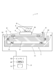
- FIG. 1 is a schematic front sectional view of a workpiece transfer device according to an embodiment.
- the workpiece transfer apparatus according to the embodiment is an apparatus that performs an operation of repeating transfer and stop, and that requires high stop position accuracy.
- the workpiece transfer apparatus according to the embodiment is mounted on a light irradiation apparatus.
- the light irradiation apparatus is an exposure apparatus, and irradiates a workpiece with a predetermined pattern of light.
- the light irradiation device includes a workpiece transfer device, a light source (not shown), and an irradiation optical system 7.
- the workpiece transfer device includes a vibration isolator 1 having vibration isolating elastic bodies 13 and 14, a base board 2 disposed on the vibration isolator 1, a base board 2, and a work W placed thereon.
- a stage 3 that is moved, a moving mechanism 4 that transports the workpiece W by moving the stage 3, and a control unit 5 that controls the moving mechanism 4.
- the exposure apparatus shown in FIG. 1 is installed in a clean room.
- the vibration isolator 1 is provided to prevent vibration from being transmitted to the stage 3 through the floor surface of the clean room.
- the moving mechanism 4 and the stage 3 are provided on the base board 2.
- the base plate 2 is a member for stably supporting the moving mechanism 4 and the stage 3 and is a so-called surface plate, and is a metal (for example, a cast metal) whose internal stress is sufficiently relaxed to prevent distortion and the like. ) Or stone.
- the vibration isolator 1 has vibration isolating elastic bodies 13 and 14.
- the vibration isolator 1 has a box shape and includes a bottom plate portion 11 and a side plate portion 12.
- a plurality of anti-vibration rubbers 13 are provided on the bottom plate 12 as anti-vibration elastic bodies that support the base board 2.
- Each side plate portion 12 is provided with a damper 14 as an anti-vibration elastic body in a state of being sandwiched between the side surfaces of the base board 2. Since each part is mounted on such an anti-vibration table 1, the surrounding vibration is not transmitted to the stage 3, and the deterioration of the stop position accuracy of the stage 3 during workpiece transfer is prevented.
- a robot may be arranged to place the workpiece W on the stage 3 or to remove the processed workpiece W from the stage 3. In this case, even if vibration is generated with the operation of the robot, it is canceled by the vibration isolation table 1 and is not transmitted to the stage 3.
- the moving mechanism 4 a mechanism that can move the stage 3 at least in the XY directions is employed.
- the XY directions are two directions parallel to the work placement surface of the stage 3 and perpendicular to each other.
- the optical axis A of the irradiation optical system 7 is perpendicular to the workpiece placement surface.
- an H type or a stack type is known, and an arbitrary one can be selected and used.
- the drive source 41 for linear movement a non-contact drive source using a magnet such as a linear motor is preferably used, but a mechanism using a ball screw may be used.
- a ⁇ -direction moving mechanism 4 that rotates the stage 3 around an axis perpendicular to the workpiece W placement surface may be added.
- the control unit 5 sends a control signal to the moving mechanism 4 so as to repeatedly move the stage 3 and stop at a predetermined position.
- the control unit 5 is a programmable control device such as a PLC, and includes a storage unit 51 such as a memory storing information for control, a processor 52, an I / O module 53, and the like.
- the workpiece transfer device includes a position sensor 6.
- a position sensor 6 As the position sensor 6, a laser interferometer is used to detect the position of the stage 3 with high accuracy.
- a reflection mirror 61 is attached to the stage 3, and the distance to the reflection mirror is measured by irradiating the reflection mirror 61 with laser light and interference between the reflection light and the reference light. Is detected.
- the position sensor 6 is connected to the control unit 5, and the detection result of the position of the stage 3 is sent to the control unit 5.
- the control unit 5 performs feedback control of the moving mechanism 4 according to the detection result of the position of the stage 3 and adjusts the stop position of the stage 3.
- a sequence program which is an important element of the workpiece transfer apparatus according to the embodiment, is installed in the storage unit 51 included in the control unit 5.
- the sequence program is a program that controls the operation of the moving mechanism 4 by sending a predetermined control signal to the moving mechanism 4 at a predetermined timing.
- the sequence control signal sent to the moving mechanism 4 includes information on how much distance stage 3 moves in which direction and information on how fast it moves. First, the former will be described.
- the light irradiation device is a device that irradiates light to a set region.
- this region is referred to as an irradiation region.
- the irradiation optical system 7 irradiates the irradiation area with a predetermined pattern of light.
- the irradiation area is indicated by an arrow R.
- the irradiation region R is often a square, but may be a circle or an ellipse.
- the irradiation area R is set as an area smaller than the workpiece W. Therefore, the irradiation pattern is also smaller than the workpiece W.
- the workpiece conveyance device of the embodiment conveys the workpiece W to the irradiation region R so that the irradiated region R ′ is adjacent on the workpiece W. “Adjacent” means that the irradiated regions R ′ are not separated from each other, and includes cases where they are in contact with each other (continuous) and partially overlapped.
- each irradiated region R 'should be positioned is designated in advance. That is, the surface of the workpiece W is divided into segments by design, and each segment is irradiated with light once to form each irradiated region R ′. Therefore, when the direction and distance of movement of the stage 3 in the workpiece transfer apparatus are indicated by an arrow T, the direction and distance of movement correspond to the length and direction of a vector connecting the centers of adjacent segments (X direction). Of course and the sum of the movements in the Y direction).
- a projection exposure apparatus such as a stepper
- one segment corresponds to one chip area.
- a two-beam interference exposure apparatus such as Patent Document 1 and Patent Document 2
- one segment is used. This corresponds to a region irradiated with interference light.
- control unit 5 causes the moving mechanism 4 to sequentially move in the distance and direction indicated by the arrow T in FIG. 1, and the time when the stage 3 is stopped (strictly settled) between the movements.
- the work W is irradiated with light in the belt.
- the control unit 5 sends a control signal including information on the moving speed to the moving mechanism 4.
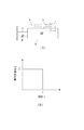
- the linear type and the non-linear type have the same meanings as differentiable and non-differentiable in calculus.
- a typical linear control pattern is the trapezoidal control shown in FIG.
- a typical non-linear control pattern, as shown in FIG. 2 (2), is a trapezoidal control in which the speed change is continuous (continuous in calculus) and is called S-shaped control.
- a set transport speed a portion that accelerates from zero speed to a set transport speed (hereinafter referred to as an acceleration section), and a set transport speed And a portion that decelerates to zero speed (hereinafter referred to as a deceleration portion).
- the portion that moves at the set conveyance speed is hereinafter referred to as a constant speed portion.
- the zero speed includes a state where the speed is substantially zero, that is, a state where the speed is set and can be regarded as substantially zero.
- the control pattern as shown in FIG. 2 is a sequence implemented in the control unit 5.
- the sequence is implemented as software, and is a sequence program implemented in the storage unit 51 included in the control unit 5. That is, the sequence program sends a control signal for accelerating at a constant speed part (a part that sends a control signal to move at a set conveyance speed) and an acceleration part (according to (1) or (2) in FIG. 2). And a deceleration part (a part that sends a control signal to decelerate at a deceleration as shown in (1) or (2) of FIG. 2).
- FIG. 2 can also be said to show the structure of such a sequence program.
- the workpiece transfer apparatus of the embodiment optimizes the time of the acceleration unit and the deceleration unit in the sequence program shown in FIG. 2 in order to shorten the time required for settling.
- the time of the acceleration unit and the deceleration unit (hereinafter referred to as acceleration time and deceleration time) is determined in relation to the natural vibration period of the vibration-proof elastic bodies 13 and 14.
- the determination of the acceleration time and the deceleration time in relation to the natural vibration period of the vibration-proof elastic bodies 13 and 14 is based on the results of inventor's earnest research on the technical configuration for shortening the settling time. .
- one having a low natural frequency (one having a small spring constant) is employed as the vibration isolating elastic bodies 13 and 14 in order to improve the vibration isolating performance.
- the base board 2 as a new problem caused by the lower natural frequency, the base board 2 as a whole sways greatly in a low cycle due to the driving reaction force (reaction force) when the stage 3 moves. I know that That is, since the base board 2 has a high rigidity and a large load, the entire structure including the moving mechanism 4 and the stage 3 on the base board 2 is likely to vibrate greatly on the vibration isolation table 1.
- a braking force in the direction opposite to the traveling direction acts on the stage.
- a reaction (driving reaction force) of the braking force acting on the stage acts in the direction of pushing out the base board 2.
- the base board 2 is completely fixed and does not move.
- the base board 2 is fixed to the vibration isolation table 1 via the vibration isolation rubber 13 and the damper 14,
- the drive reaction force causes itself to vibrate. Since the stage 3 is a part of the structure, the fact that the structure vibrates greatly means that the stage 3 vibrates.
- the workpiece transfer apparatus includes a position sensor 6 such as a laser interferometer for monitoring the stop position of the stage 3, and a position measurement signal from the position sensor 6 is sent to the control unit 5, and feedback control of the stop position is performed. Is done. In this case, if vibration due to the driving reaction force is generated in the base board 2 at the end of the speed reduction section, the stage 3 on the base board 2 is also vibrating. 5 gives feedback. In this case, the control target of the control unit 5 is the stage 3 and not the base board 2. Even if the control unit 5 sends a control signal to the moving mechanism 4 to operate the moving mechanism 4 in a direction to cancel the vibration, the vibration of the base board 2 is not directly affected, and the vibration is caused by the action of the damper 14 or the like.
- a position sensor 6 such as a laser interferometer for monitoring the stop position of the stage 3, and a position measurement signal from the position sensor 6 is sent to the control unit 5, and feedback control of the stop position is performed. Is done. In this case, if vibration due
- the inventor diligently studied a new problem caused by the interaction between the vibration of the base board 2 and the feedback control of the stop position of the stage 3.
- the magnitude of the vibration of the base board 2 is related to the length of the acceleration time and the deceleration time of the stage 3 on the base board 2. As this time is changed, the base board 2 periodically It has been found that there are acceleration times and deceleration times at which vibrations are minimized.
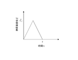
- FIG. 3 is a study diagram on the vibration of the structure.
- the structure includes the base board 2, the stage 3 on the base board 2, and the moving mechanism 4 thereof.
- the weight of the structure is M
- the spring constant between the structure and the vibration isolator 1 the whole spring of the anti-vibration rubber 13 and the damper 14 as an elastic body for vibration isolation. If the constant is k and the viscous friction coefficient is c, the vibration of the structure is given by the equation of motion of Equation 1 below.
- the external force F (t) here means a driving reaction force (F ′ in FIG. 3).
- Expression 3 is obtained.
- formula 4 is obtained.
- T n is the natural vibration period of the vibration isolating elastic bodies 13 and 14 (the total natural vibration period of the two elastic bodies 13 and 14), and ⁇ n is the angular frequency thereof.
- the external force F (t) is a driving reaction force against the braking force (brake) to the stage 3. Therefore, it becomes zero at time ⁇ from the time when the braking force starts to work.
- Time ⁇ is the time when the braking force to the stage 3 becomes zero, and is the end time of the deceleration unit in the sequence of FIG. That is, as shown in FIG. 3 (2), the static load displacement ⁇ (t) due to the driving reaction force F (t) has a value of ⁇ p when 0 ⁇ t ⁇ and a value of 0 when t ⁇ ⁇ .
- the Laplace inverse transform is performed by solving the equation 4, the following equation 5 is obtained.
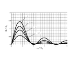
- FIG. 4 is a diagram illustrating an example of a vibration waveform of a structure due to a driving reaction force in the workpiece transfer apparatus according to the embodiment.
- ⁇ 0.2
- ⁇ n 31.4 rad / s
- T n 200 milliseconds.
- the horizontal axis in FIG. 4 is the time normalized by the deceleration time ⁇
- the vertical axis is the amplitude normalized by the static load displacement ⁇ p due to the drive reaction force.
- the value of the first peak of vibration after the end of deceleration (hereinafter referred to as initial vibration peak) varies depending on the deceleration time ⁇ .
- FIG. 5 is a diagram showing the above points, and is a diagram showing the result of further analysis of the example of FIG.
- the vertical axis in FIG. 5 is the initial peak normalized by the static load displacement ⁇ p
- the horizontal axis is the deceleration time ⁇ normalized by the natural vibration period T n of the vibration isolating elastic bodies 13 and 14.
- the deceleration time ⁇ is set to a natural number multiple of the natural vibration period T n of the vibration-proof elastic member 13, the initial vibrational peak has a minimum value.
- FIG. 6 is a diagram illustrating a braking force in the S-shaped control.
- FIG. 7 is a diagram similar to FIG. 5 and shows the relationship between the deceleration time ⁇ and the initial peak in the case of S-shaped control.
- the time of deceleration is similarly taken, and it is assumed that a braking force (so-called triangular wave) that peaks at an intermediate point in time during the deceleration time ⁇ is applied to the stage 3. Therefore, the conditions of the driving reaction force are the same, and a triangular waveform in which the static load displacement becomes the peak value ⁇ p at the intermediate point of the deceleration time ⁇ .
- FIG. 7 is a diagram showing a result of examining the dependency of the initial peak on the deceleration time by performing the same analysis under the above conditions.
- the horizontal axis is standardized by the natural vibration period T n of the vibration-proof elastic member 13, the vertical axis is normalized by the peak value xi] p static load displacement.
- the initial vibration peak has a minimum value when the deceleration time ⁇ is 2n times the natural vibration period T n of the vibration-proof elastic bodies 13 and 14 (n is a natural number). .
- the deceleration time ⁇ is n times the natural vibration period of the vibration isolating elastic bodies 13 and 14 in the case of trapezoidal control, and in the case of S-shaped control. Is 2n times, the initial vibration peak has a minimum value.
- the initial vibration peak is small, the time until the vibration is reduced is shortened. That is, the time required for settling is shortened.
- the acceleration time for acceleration is set to n times the natural vibration period of the anti-vibration elastic bodies 13 and 14 in the case of trapezoidal control, and 2n times in the case of S-shaped control. If this is done, the initial vibration peak becomes smaller and the time required for settling can be shortened.
- vibration due to the driving reaction force starts when the constant speed part (movement at the set conveyance speed) is reached, and the vibration is attenuated during operation of the constant speed part (moves in a state where the vibration is superimposed).
- the impact is not as serious as in the case of deceleration. That is, the vibration generated by the acceleration unit may be sufficiently damped when it reaches the deceleration unit. Nevertheless, when the time of the constant speed portion is short, there is a possibility that the influence is not a little, so it is preferable to do as described above.
- the workpiece transfer apparatus of this embodiment has a configuration in which the sequence in the control unit 5 is optimized based on the above examination and analysis.
- the sequence program stored in the storage unit 51 of the control unit 5 has an acceleration unit and a deceleration unit, and the time of the deceleration unit is the first peak of the vibration of the base board 2 after the termination of the deceleration unit. Is the time that is less than half of the maximum value.
- the time of the acceleration part in the said sequence is time when the first peak of the vibration of the base board 2 after completion
- the time of the deceleration unit and the time of the acceleration unit are set to a value that is n times the natural vibration period of the vibration isolating elastic bodies 13 and 14. It is set to a value 2n times the natural vibration period of the elastic elastic bodies 13 and 14 for use. From the viewpoint of increasing productivity, n is preferably as small as possible, and is preferably 1 or 2.
- Control unit 5 executes a sequence program when the transport of the workpiece W, to move the stage 3 in the acceleration time and deceleration time 2nT n or nT n. After the sequence of the deceleration unit is completed, the base board 2 vibrates due to the driving reaction force, and the stage 3 also vibrates integrally therewith, but the acceleration time and the deceleration time are optimized, so the vibration occurs within a short period of time. Converge and reach settling.
- FIG. 8 and FIG. 9 are diagrams showing the results of an experiment confirming the effect of the workpiece transfer device of the embodiment.
- FIG. 8 shows the result for the workpiece transfer apparatus of the embodiment
- FIG. 9 shows the result for the workpiece transfer apparatus of the reference example.
- the embodiment (FIG. 8) the natural period T n of the vibration-proof elastic member is 200 msec, the acceleration is trapezoidal control, the deceleration was set to S-control.
- FIG. 8 (1) shows the displacement (calculated value, actually measured value) of the base board 2 as the stage 3 moves, and also shows the speed command pattern of the stage 3. Further, FIG. 8 (2) shows a measured value of the displacement amount of the stage 3 when the displacement of the base board 2 shown in FIG. 8 (1) is measured.
- FIG. 9 shows the displacement amount (calculated value, actual measurement value) of the base board 2 as the stage 3 moves together with the speed command pattern of the stage 3 in the apparatus of the reference example.
- FIG. 9 (2) shows a measured value of the displacement amount of the stage 3 when the displacement of the base board 2 shown in FIG. 9 (1) is measured.
- the stage 3 when the stage 3 is moved in the Y direction, the stage 3 is also displaced in the X direction, and is also displaced in the ⁇ direction.
- the vibration of the base board 2 converges promptly after the speed reduction portion is finished. Then, as shown in FIG. 8 (2), it can be seen that the stage 3 has reached settling in a short time.
- the vibration of the base board 2 has a large amplitude and continues for a long time after the end of the deceleration portion. Then, as shown in FIG. 9 (2), the stage 3 vibrates violently not only in the Y direction but also in the X direction and the ⁇ direction after completion of the speed reduction portion, and it takes a long time to settle. I understand that.
- the overall operation of the light irradiation apparatus on which the workpiece transfer apparatus of such an embodiment is mounted will be schematically described below.
- the wafer as the workpiece W is transferred from the previous process to the light irradiation device by a transfer device such as an AGV (Automated Guided vehicle).
- the stage 3 is waiting in advance at a predetermined load position.
- a loading mechanism such as a robot operates at the loading position, and the workpiece W is placed on the stage 3.
- the moving mechanism 4 moves the stage 3 on the base board 2 and stops the stage 3 at a position where the first segment in the workpiece W coincides with the irradiation region R.
- the irradiation optical system 7 irradiates the irradiation area with light.
- the moving mechanism 4 is operated to move the stage 3 in the X direction and / or the Y direction so that the next segment is positioned in the irradiation region. And light irradiation is repeated similarly.
- the stage 3 repeats movement and stop many times in order to irradiate each segment of the workpiece W.
- the time to settling at the time of stop is short, Light irradiation can be started. For this reason, the entire processing time required for one work W can be significantly shortened.
- the light irradiation apparatus is a two-beam interference exposure apparatus that irradiates the light with the chip area divided into a number of segments, the number of times of movement and stop is very large, so the above effect is remarkable.
- the light irradiation may be performed on the entire surface of the workpiece (surface on the side of the irradiation optical system).
- a grid polarizing element which is a kind of polarizing plate, has been studied as an application of a two-beam interference exposure apparatus.
- the grid having a polarizing action is a line and space formed on the surface on one side of the substrate, and is formed over the entire surface. For this reason, light irradiation is performed to the whole area.
- the deceleration time and the acceleration time, nT n in the case of the trapezoid control was the 2nT n in the case of the S-shaped control, as seen from FIG. 5 and FIG. 7, the time length before and after It is effective even if it exists. That is, when the S-shaped control is greater 1 / 2T n less than 0, or ⁇ (2n-1) +1/2 ⁇ T n or (2n + 1/2) may be a T n less time, trapezoidal control more than 0 to 1 / 4T n or less in the case of, or ⁇ (n-1) +3/4 ⁇ T n or (n + 1/4) T n may be a less time.
- the use of the work transfer device is not limited to an exposure device or other light irradiation device, and may be used for a device that performs processing other than light irradiation, such as a wafer bonding device.
- the sequence is implemented by software. However, the sequence may be implemented by hardware.
- an elastic body for anti-vibration is an anti-vibration stand and a floor surface. It may be interposed between the two.
- the base board corresponds to the vibration isolator.
- the moving mechanism 4 moves the stage 3 in the XY directions, the stage 3 may be moved only in one direction when the present invention is implemented. In that case, the control unit may instruct the moving mechanism 4 only of the moving distance.
Landscapes
- Physics & Mathematics (AREA)
- General Physics & Mathematics (AREA)
- Nonlinear Science (AREA)
- Engineering & Computer Science (AREA)
- Automation & Control Theory (AREA)
- Crystallography & Structural Chemistry (AREA)
- Chemical & Material Sciences (AREA)
- Optics & Photonics (AREA)
- Mechanical Engineering (AREA)
- Exposure And Positioning Against Photoresist Photosensitive Materials (AREA)
- Liquid Crystal (AREA)
- Container, Conveyance, Adherence, Positioning, Of Wafer (AREA)
- Exposure Of Semiconductors, Excluding Electron Or Ion Beam Exposure (AREA)
Abstract
【課題】 高い停止位置精度で搬送と停止を繰り返すことができ、生産性を悪化させることのないワーク搬送装置を提供する。 【解決手段】 防振用弾性体13,14を介して防振台1上に配置されたベース盤2の上にステージ3が配置され、ステージ3を移動機構4が移動させることでステージ3上のワークWが搬送される。制御部5に実装されたステージの移動速度のシーケンスにおいて、加速時間及び減速時間は、加減速部の終了後の駆動反力によるベース盤2の振動の最初のピークが防振用弾性体13,14の固有振動周期との関係において最大値の半分以下となる時間である。
Description
この出願の発明は、露光装置におけるアライメントのように、ワークを高い停止位置精度で搬送するワーク搬送の技術に関する。
処理の対象物(以下、ワークという)をステージに載置して所定の位置に搬送するワーク搬送装置は、各種処理装置において盛んに使用されている。例えば、微細回路の形成等の目的で使用される露光装置では、露光を行う光学系に対して所定の位置にワークを搬送するため、ワーク搬送装置が使用されている。この種の用途のワーク搬送装置は、製品の高性能化、高機能化を背景として非常に高い停止位置精度が要求されている。その一方、多くの場合、ワークは設計上各セグメントに分割され、各セグメントに対して高い位置精度で処理を行う必要がある。このため、この種のワーク搬送装置は、搬送と所定位置での停止を繰り返す動作が要求される。上記露光装置のうちでもいわゆるステップアンドリピートと呼ばれる動作を行う装置(ステッパー)が、その一例である。
上記のように搬送と所定位置での停止を繰り返す動作を行うワーク搬送装置については、停止位置精度の向上とともに、そのように高い位置精度での停止が完了するまでの時間を短くすることが要求される。具体的に説明すると、ある位置からステージが移動してある位置に停止する際、ステージは、当該位置ですぐには停止できない。慣性により移動を続けようとする力に抗して作用する制動(ブレーキ)力が作用し、後者が前者を上回ることでステージが停止するが、反動(残留する制動力)の影響でステージは微動を続ける。即ち、ステージの位置を検出してフィードバック制御を行うような制御系(サーボ系)が採用されており、このため、反動による微動を解消するように逆向きの駆動が行われ、結果的にステージは細かく振動する状態となる。この微動(振動)は、摩擦力等により減衰し、微動が十分に小さくなった状態が厳密には“停止”という状態である。本明細書において、このようにステージの微動が十分に小さくなった状態を「整定」という。
搬送と所定位置での停止を繰り返す動作を行うワーク搬送装置の場合、整定に要する時間を短くすることが特に求められる。整定に長時間を要すると、全体の処理時間が長くなり、生産性が低下する。搬送速度を高くすることも考えられるが、搬送速度を高くすると反動や残留振動(フィードバック制御によるものも含む)が大きくなり、整定に長時間を要してしまう。どの程度まで反動や残留振動が小さくなったら整定したとして良いかは、用途(整定後に行われる処理)によって変わる。露光装置のような高精度の位置合わせが要求される装置では、反動や残留振動は特に小さくすることが求められ、このため整定に要する時間はどうしても長くなってしまう。この点は、生産性向上を阻害する要因となっている。また、残留振動を除去する技術として空圧式等のアクティブ除振動技術やカウンターマス等の反力低減技術が実用化されているが、構成が複雑であり、また高コストとなり易いという欠点がある。
上記問題は、最近検討されている二光束干渉露光を行う露光装置の場合、特に顕著である。二光束干渉露光とは、レーザー光を二つの光束に分け、ワーク上で干渉させて露光する方式を指す。この二光束干渉露光において、特許文献1に開示されているように、歪みのない像を転写するため、光軸付近の小さいエリアに像を制限して露光することが検討されており、1回の露光における光照射領域は非常に小さいものとなっている。このため、1つのワークについて例えば352回(特許文献1)もの露光を繰り返す必要があり、このように非常に多くの回数の移動と停止を高い精度で行うことが要求されている。したがって、上記整定に要する時間の長期化の問題は深刻である。
本願の発明は、このような課題を解決するために為されたものであり、搬送と停止を繰り返す動作が要求され且つ高い停止位置精度が要求される場合に好適に使用されるワーク搬送装置であって、生産性を悪化させることなく要求を十分に満足できるワーク搬送装置を提供することを目的としている。
本願の発明は、このような課題を解決するために為されたものであり、搬送と停止を繰り返す動作が要求され且つ高い停止位置精度が要求される場合に好適に使用されるワーク搬送装置であって、生産性を悪化させることなく要求を十分に満足できるワーク搬送装置を提供することを目的としている。
上記課題を解決するため、この出願の請求項1記載の発明は、
防振用弾性体を有する防振台と、
防振台の上に配置されたベース盤と、
ベース盤の上に配置され、ワークが載置されるステージと、
ステージを移動させることでワークを搬送する移動機構と、
移動機構を制御する制御部と
を備えており、
制御部は、移動機構によるステージの移動速度のシーケンスを実装しており、当該実装されたシーケンスでステージを移動させる制御信号を移動機構に送るものであり、
移動速度のシーケンスは、速度ゼロから設定搬送速度まで速度を上昇させる加速部と、設定搬送速度を維持する定速部と、設定搬送速度から速度ゼロまで速度を低下させる減速部とを有するシーケンスであり、
減速部の時間は、減速部の終了後の駆動反力によるベース盤の振動の最初のピークが防振用弾性体の固有振動周期との関係において最大値の半分以下となる時間であるという構成を有する。
また、上記課題を解決するため、請求項2記載の発明は、前記請求項1の構成において、前記加速部の時間は、前記加速部の終了後の駆動反力による前記ベース盤の振動の最初のピークが前記防振用弾性体の固有振動周期との関係において最大値の半分以下となる時間であるという構成を有する。
また、上記課題を解決するため、請求項3記載の発明は、前記請求項1又は2の構成において、前記加速部は、前記ステージの移動速度を線型的に上昇させるシーケンスであり、
前記減速部は、前記ステージの移動速度を線型的に低下させるシーケンスであり、
前記減速部の時間は、前記防振用弾性体の固有振動周期をTnとし、nを自然数としたとき、0より大きく1/4Tn以下、又は{(n-1)+3/4}Tn以上(n+1/4)Tn以下の時間であるという構成を有する。
また、上記課題を解決するため、請求項4記載の発明は、前記請求項2の構成において、前記加速部は、前記ステージの移動速度を線型的に上昇させるシーケンスであり、
前記減速部は、前記ステージの移動速度を線型的に低下させるシーケンスであり、
前記加速部の時間は、前記防振用弾性体の固有振動周期をTnとし、nを自然数としたとき、0より大きく1/4Tn以下、又は{(n-1)+3/4}Tn以上(n+1/4)Tn以下の時間である
という構成を有する。
また、上記課題を解決するため、請求項5記載の発明は、前記請求項1又は2の構成において、前記加速部は、前記ステージの移動速度を線型的に上昇させるシーケンスであり、
前記減速部は、前記ステージの移動速度を線型的に低下させるシーケンスであり、
前記減速部の時間は、nTnの時間であるという構成を有する。
また、上記課題を解決するため、請求項6記載の発明は、前記請求項2の構成において、前記加速部は、前記ステージの移動速度を線型的に上昇させるシーケンスであり、
前記減速部は、前記ステージの移動速度を線型的に低下させるシーケンスであり、
前記加速部の時間は、nTnの時間であるという構成を有する。
また、上記課題を解決するため、請求項7記載の発明は、前記請求項1又は2の構成において、前記加速部は、前記ステージの移動速度を非線型的に上昇させるシーケンスであり、
前記減速部は、前記ステージの移動速度を非線型的に低下させるシーケンスであり、
前記減速部の時間は、前記防振用弾性体の固有振動周期をTnとし、nを自然数としたとき、0より大きく1/2Tn以下、又は{(2n-1)+1/2}Tn以上(2n+1/2)Tn以下の時間であるという構成を有する。
また、上記課題を解決するため、請求項8記載の発明は、前記請求項2の構成において、前記加速部は、前記ステージの移動速度を非線型的に上昇させるシーケンスであり、
前記減速部は、前記ステージの移動速度を非線型的に低下させるシーケンスであり、
前記加速部の時間は、前記防振用弾性体の固有振動周期をTnとし、nを自然数としたとき、0より大きく1/2Tn以下、又は{(2n-1)+1/2}Tn以上(2n+1/2)Tn以下の時間であるという構成を有する。
また、上記課題を解決するため、請求項9記載の発明は、前記請求項1又は2の構成において、前記加速部は、前記ステージの移動速度を非線型的に上昇させるシーケンスであり、
前記減速部は、前記ステージの移動速度を非線型的に低下させるシーケンスであり、
前記減速部の時間は、2nTnの時間であるという構成を有する。
また、上記課題を解決するため、請求項10記載の発明は、前記請求項2の構成において、前記加速部は、前記ステージの移動速度を非線型的に上昇させるシーケンスであり、
前記減速部は、前記ステージの移動速度を非線型的に低下させるシーケンスであり、
前記加速部の時間は、2nTnの時間であるという構成を有する。
また、上記課題を解決するため、請求項11記載の発明は、前記請求項1乃至10いずれかの構成において、前記防振用弾性体の固有振動周期は0.1秒以上であるという構成を有する。
防振用弾性体を有する防振台と、
防振台の上に配置されたベース盤と、
ベース盤の上に配置され、ワークが載置されるステージと、
ステージを移動させることでワークを搬送する移動機構と、
移動機構を制御する制御部と
を備えており、
制御部は、移動機構によるステージの移動速度のシーケンスを実装しており、当該実装されたシーケンスでステージを移動させる制御信号を移動機構に送るものであり、
移動速度のシーケンスは、速度ゼロから設定搬送速度まで速度を上昇させる加速部と、設定搬送速度を維持する定速部と、設定搬送速度から速度ゼロまで速度を低下させる減速部とを有するシーケンスであり、
減速部の時間は、減速部の終了後の駆動反力によるベース盤の振動の最初のピークが防振用弾性体の固有振動周期との関係において最大値の半分以下となる時間であるという構成を有する。
また、上記課題を解決するため、請求項2記載の発明は、前記請求項1の構成において、前記加速部の時間は、前記加速部の終了後の駆動反力による前記ベース盤の振動の最初のピークが前記防振用弾性体の固有振動周期との関係において最大値の半分以下となる時間であるという構成を有する。
また、上記課題を解決するため、請求項3記載の発明は、前記請求項1又は2の構成において、前記加速部は、前記ステージの移動速度を線型的に上昇させるシーケンスであり、
前記減速部は、前記ステージの移動速度を線型的に低下させるシーケンスであり、
前記減速部の時間は、前記防振用弾性体の固有振動周期をTnとし、nを自然数としたとき、0より大きく1/4Tn以下、又は{(n-1)+3/4}Tn以上(n+1/4)Tn以下の時間であるという構成を有する。
また、上記課題を解決するため、請求項4記載の発明は、前記請求項2の構成において、前記加速部は、前記ステージの移動速度を線型的に上昇させるシーケンスであり、
前記減速部は、前記ステージの移動速度を線型的に低下させるシーケンスであり、
前記加速部の時間は、前記防振用弾性体の固有振動周期をTnとし、nを自然数としたとき、0より大きく1/4Tn以下、又は{(n-1)+3/4}Tn以上(n+1/4)Tn以下の時間である
という構成を有する。
また、上記課題を解決するため、請求項5記載の発明は、前記請求項1又は2の構成において、前記加速部は、前記ステージの移動速度を線型的に上昇させるシーケンスであり、
前記減速部は、前記ステージの移動速度を線型的に低下させるシーケンスであり、
前記減速部の時間は、nTnの時間であるという構成を有する。
また、上記課題を解決するため、請求項6記載の発明は、前記請求項2の構成において、前記加速部は、前記ステージの移動速度を線型的に上昇させるシーケンスであり、
前記減速部は、前記ステージの移動速度を線型的に低下させるシーケンスであり、
前記加速部の時間は、nTnの時間であるという構成を有する。
また、上記課題を解決するため、請求項7記載の発明は、前記請求項1又は2の構成において、前記加速部は、前記ステージの移動速度を非線型的に上昇させるシーケンスであり、
前記減速部は、前記ステージの移動速度を非線型的に低下させるシーケンスであり、
前記減速部の時間は、前記防振用弾性体の固有振動周期をTnとし、nを自然数としたとき、0より大きく1/2Tn以下、又は{(2n-1)+1/2}Tn以上(2n+1/2)Tn以下の時間であるという構成を有する。
また、上記課題を解決するため、請求項8記載の発明は、前記請求項2の構成において、前記加速部は、前記ステージの移動速度を非線型的に上昇させるシーケンスであり、
前記減速部は、前記ステージの移動速度を非線型的に低下させるシーケンスであり、
前記加速部の時間は、前記防振用弾性体の固有振動周期をTnとし、nを自然数としたとき、0より大きく1/2Tn以下、又は{(2n-1)+1/2}Tn以上(2n+1/2)Tn以下の時間であるという構成を有する。
また、上記課題を解決するため、請求項9記載の発明は、前記請求項1又は2の構成において、前記加速部は、前記ステージの移動速度を非線型的に上昇させるシーケンスであり、
前記減速部は、前記ステージの移動速度を非線型的に低下させるシーケンスであり、
前記減速部の時間は、2nTnの時間であるという構成を有する。
また、上記課題を解決するため、請求項10記載の発明は、前記請求項2の構成において、前記加速部は、前記ステージの移動速度を非線型的に上昇させるシーケンスであり、
前記減速部は、前記ステージの移動速度を非線型的に低下させるシーケンスであり、
前記加速部の時間は、2nTnの時間であるという構成を有する。
また、上記課題を解決するため、請求項11記載の発明は、前記請求項1乃至10いずれかの構成において、前記防振用弾性体の固有振動周期は0.1秒以上であるという構成を有する。
また、上記課題を解決するため、請求項12記載の発明は、前記請求項1乃至11いずれかに記載のワーク搬送装置と、
光源と、
光源からの光を前記ステージに載置されたワークに照射する照射光学系と
を備えた光照射装置であって、
照射光学系は、ワークよりも小さい照射パターンで光照射する光学系であり、
前記移動機構による移動距離は、当該照射パターンで光照射された領域がワーク上で隣接する距離として設定されており、
光源及び照射光学系は、前記ステージの停止中にワークに光照射するものであるという構成を有する。
また、上記課題を解決するため、請求項13記載の発明は、請求項1乃至11いずれかに記載のワーク搬送装置と、
光源と、
光源からの光を前記ステージに載置されたワークに照射する照射光学系と
を備えた光照射装置であって、
前記光源及び前記照射光学系は、前記移動機構による前記ステージの移動中にワークに光を照射するものであるという構成を有する。
光源と、
光源からの光を前記ステージに載置されたワークに照射する照射光学系と
を備えた光照射装置であって、
照射光学系は、ワークよりも小さい照射パターンで光照射する光学系であり、
前記移動機構による移動距離は、当該照射パターンで光照射された領域がワーク上で隣接する距離として設定されており、
光源及び照射光学系は、前記ステージの停止中にワークに光照射するものであるという構成を有する。
また、上記課題を解決するため、請求項13記載の発明は、請求項1乃至11いずれかに記載のワーク搬送装置と、
光源と、
光源からの光を前記ステージに載置されたワークに照射する照射光学系と
を備えた光照射装置であって、
前記光源及び前記照射光学系は、前記移動機構による前記ステージの移動中にワークに光を照射するものであるという構成を有する。
また、上記課題を解決するため、請求項14記載の発明は、防振用弾性体を有する防振台と、
防振台の上に配置されたベース盤と、
ベース盤の上に配置されたステージと、
ステージを移動させることでワークを搬送する移動機構と、
移動機構を制御する制御部と
を備えたワーク搬送装置を使用してワークを搬送するワーク搬送方法であって、
ワークをステージに載置する載置ステップと、
ワークが載置されたステージを移動させることでワークを搬送する搬送ステップと
を有しており、
制御部は、移動機構によるステージの移動速度のシーケンスを実装しており、搬送ステップは、当該実装されたシーケンスでステージを移動させる制御信号を制御部が移動機構に送ることで搬送を行うステップであり、
移動速度のシーケンスは、速度ゼロから設定搬送速度まで速度を上昇させる加速部と、設定搬送速度を維持する定速部と、設定搬送速度から速度ゼロまで速度を低下させる減速部とを有するシーケンスであり、
減速部の時間は、減速部の終了後の駆動反力によるベース盤の振動の最初のピークが防振用弾性体の固有振動周期との関係において最大値の半分以下になる時間であるという構成を有する。
また、上記課題を解決するため、請求項15記載の発明は、前記請求項14の構成において、前記加速部の時間は、前記加速部の終了後の駆動反力によるベース盤の振動の最初のピークが前記防振用弾性体の固有振動周期との関係において最大値の半分以下となる時間であるという構成を有する。
また、上記課題を解決するため、請求項16記載の発明は、前記請求項14又は15の構成において、前記加速部は、前記ステージの移動速度を線型的に上昇させるシーケンスであり、
前記減速部は、前記ステージの移動速度を線型的に低下させるシーケンスであり、
前記減速部の時間は、前記防振用弾性体の固有振動周期をTnとし、nを自然数としたとき、0より大きく1/4Tn以下、又は{(n-1)+3/4}Tn以上(n+1/4)Tn以下の時間であるという構成を有する。
また、上記課題を解決するため、請求項17記載の発明は、前記請求項15の構成において、前記加速部は、前記ステージの移動速度を線型的に上昇させるシーケンスであり、
前記減速部は、前記ステージの移動速度を線型的に低下させるシーケンスであり、
前記加速部の時間は、前記防振用弾性体の固有振動周期をTnとし、nを自然数としたとき、0より大きく1/4Tn以下、又は{(n-1)+3/4}Tn以上(n+1/4)Tn以下の時間であるという構成を有する。
また、上記課題を解決するため、請求項18記載の発明は、前記請求項14又は15の構成において、前記加速部は、前記ステージの移動速度を線型的に上昇させるシーケンスであり、
前記減速部は、前記ステージの移動速度を線型的に低下させるシーケンスであり、
前記減速部の時間は、nTnの時間であるという構成を有する。
また、上記課題を解決するため、請求項19記載の発明は、前記請求項15の構成において、前記加速部は、前記ステージの移動速度を線型的に上昇させるシーケンスであり、
前記減速部は、前記ステージの移動速度を線型的に低下させるシーケンスであり、
前記加速部の時間は、nTnの時間であるという構成を有する。
また、上記課題を解決するため、請求項20記載の発明は、前記請求項14又は15の構成において、前記加速部は、前記ステージの移動速度を非線型的に上昇させるシーケンスであり、
前記減速部は、前記ステージの移動速度を非線型的に低下させるシーケンスであり、
前記減速部の時間は、前記防振用弾性体の固有振動周期をTnとし、nを自然数としたとき、0より大きく1/2Tn以下、又は{(2n-1)+1/2}Tn以上(2n+1/2)Tn以下の時間であるという構成を有する。
また、上記課題を解決するため、請求項21記載の発明は、前記請求項15の構成において、前記加速部は、前記ステージの移動速度を非線型的に上昇させるシーケンスであり、
前記減速部は、前記ステージの移動速度を非線型的に低下させるシーケンスであり、
前記加速部の時間は、前記防振用弾性体の固有振動周期をTnとし、nを自然数としたとき、0より大きく1/2Tn以下、又は{(2n-1)+1/2}Tn以上(2n+1/2)Tn以下の時間であるという構成を有する。
また、上記課題を解決するため、請求項22記載の発明は、前記請求項14又は15の構成において、前記加速部は、前記ステージの移動速度を非線型的に上昇させるシーケンスであり、
前記減速部は、前記ステージの移動速度を非線型的に低下させるシーケンスであり、
前記減速部の時間は、2nTnの時間であるという構成を有する。
また、上記課題を解決するため、請求項23記載の発明は、前記請求項14又は15の構成において、前記加速部は、前記ステージの移動速度を非線型的に上昇させるシーケンスであり、
前記減速部は、前記ステージの移動速度を非線型的に低下させるシーケンスであり、
前記加速部の時間は、2nTnの時間であるという構成を有する。
また、上記課題を解決するため、請求項24記載の発明は、前記請求項14乃至23の構成において、前記防振用弾性体の固有振動周期は0.1秒以上であるという構成を有する。
防振台の上に配置されたベース盤と、
ベース盤の上に配置されたステージと、
ステージを移動させることでワークを搬送する移動機構と、
移動機構を制御する制御部と
を備えたワーク搬送装置を使用してワークを搬送するワーク搬送方法であって、
ワークをステージに載置する載置ステップと、
ワークが載置されたステージを移動させることでワークを搬送する搬送ステップと
を有しており、
制御部は、移動機構によるステージの移動速度のシーケンスを実装しており、搬送ステップは、当該実装されたシーケンスでステージを移動させる制御信号を制御部が移動機構に送ることで搬送を行うステップであり、
移動速度のシーケンスは、速度ゼロから設定搬送速度まで速度を上昇させる加速部と、設定搬送速度を維持する定速部と、設定搬送速度から速度ゼロまで速度を低下させる減速部とを有するシーケンスであり、
減速部の時間は、減速部の終了後の駆動反力によるベース盤の振動の最初のピークが防振用弾性体の固有振動周期との関係において最大値の半分以下になる時間であるという構成を有する。
また、上記課題を解決するため、請求項15記載の発明は、前記請求項14の構成において、前記加速部の時間は、前記加速部の終了後の駆動反力によるベース盤の振動の最初のピークが前記防振用弾性体の固有振動周期との関係において最大値の半分以下となる時間であるという構成を有する。
また、上記課題を解決するため、請求項16記載の発明は、前記請求項14又は15の構成において、前記加速部は、前記ステージの移動速度を線型的に上昇させるシーケンスであり、
前記減速部は、前記ステージの移動速度を線型的に低下させるシーケンスであり、
前記減速部の時間は、前記防振用弾性体の固有振動周期をTnとし、nを自然数としたとき、0より大きく1/4Tn以下、又は{(n-1)+3/4}Tn以上(n+1/4)Tn以下の時間であるという構成を有する。
また、上記課題を解決するため、請求項17記載の発明は、前記請求項15の構成において、前記加速部は、前記ステージの移動速度を線型的に上昇させるシーケンスであり、
前記減速部は、前記ステージの移動速度を線型的に低下させるシーケンスであり、
前記加速部の時間は、前記防振用弾性体の固有振動周期をTnとし、nを自然数としたとき、0より大きく1/4Tn以下、又は{(n-1)+3/4}Tn以上(n+1/4)Tn以下の時間であるという構成を有する。
また、上記課題を解決するため、請求項18記載の発明は、前記請求項14又は15の構成において、前記加速部は、前記ステージの移動速度を線型的に上昇させるシーケンスであり、
前記減速部は、前記ステージの移動速度を線型的に低下させるシーケンスであり、
前記減速部の時間は、nTnの時間であるという構成を有する。
また、上記課題を解決するため、請求項19記載の発明は、前記請求項15の構成において、前記加速部は、前記ステージの移動速度を線型的に上昇させるシーケンスであり、
前記減速部は、前記ステージの移動速度を線型的に低下させるシーケンスであり、
前記加速部の時間は、nTnの時間であるという構成を有する。
また、上記課題を解決するため、請求項20記載の発明は、前記請求項14又は15の構成において、前記加速部は、前記ステージの移動速度を非線型的に上昇させるシーケンスであり、
前記減速部は、前記ステージの移動速度を非線型的に低下させるシーケンスであり、
前記減速部の時間は、前記防振用弾性体の固有振動周期をTnとし、nを自然数としたとき、0より大きく1/2Tn以下、又は{(2n-1)+1/2}Tn以上(2n+1/2)Tn以下の時間であるという構成を有する。
また、上記課題を解決するため、請求項21記載の発明は、前記請求項15の構成において、前記加速部は、前記ステージの移動速度を非線型的に上昇させるシーケンスであり、
前記減速部は、前記ステージの移動速度を非線型的に低下させるシーケンスであり、
前記加速部の時間は、前記防振用弾性体の固有振動周期をTnとし、nを自然数としたとき、0より大きく1/2Tn以下、又は{(2n-1)+1/2}Tn以上(2n+1/2)Tn以下の時間であるという構成を有する。
また、上記課題を解決するため、請求項22記載の発明は、前記請求項14又は15の構成において、前記加速部は、前記ステージの移動速度を非線型的に上昇させるシーケンスであり、
前記減速部は、前記ステージの移動速度を非線型的に低下させるシーケンスであり、
前記減速部の時間は、2nTnの時間であるという構成を有する。
また、上記課題を解決するため、請求項23記載の発明は、前記請求項14又は15の構成において、前記加速部は、前記ステージの移動速度を非線型的に上昇させるシーケンスであり、
前記減速部は、前記ステージの移動速度を非線型的に低下させるシーケンスであり、
前記加速部の時間は、2nTnの時間であるという構成を有する。
また、上記課題を解決するため、請求項24記載の発明は、前記請求項14乃至23の構成において、前記防振用弾性体の固有振動周期は0.1秒以上であるという構成を有する。
また、上記課題を解決するため、請求項25記載の発明は、請求項1乃至11いずれかに記載のワーク搬送装置を使用してワークに光照射する光照射方法であって、
前記ステージ停止している際に前記ステージに載置されたワークに対し、光源からの光を当該ワークよりも小さい照射パターンで照射する照射ステップと、
前記移動機構を動作させてワークを搬送する搬送ステップとを繰り返す光照射方法であり、
各照射ステップで光照射された領域がワーク上で隣接するという構成を有する。
また、上記課題を解決するため、請求項26記載の発明は、請求項1乃至11いずれかに記載のワーク搬送装置を使用してワークに光照射する光照射方法であって、
前記ステージが前記移動機構により移動している際に前記ステージに載置されたワークに対して光源からの光を照射するという構成を有する。
前記ステージ停止している際に前記ステージに載置されたワークに対し、光源からの光を当該ワークよりも小さい照射パターンで照射する照射ステップと、
前記移動機構を動作させてワークを搬送する搬送ステップとを繰り返す光照射方法であり、
各照射ステップで光照射された領域がワーク上で隣接するという構成を有する。
また、上記課題を解決するため、請求項26記載の発明は、請求項1乃至11いずれかに記載のワーク搬送装置を使用してワークに光照射する光照射方法であって、
前記ステージが前記移動機構により移動している際に前記ステージに載置されたワークに対して光源からの光を照射するという構成を有する。
以下に説明する通り、この出願の請求項1乃至11、14乃至24いずれかの発明によれば、ステージの移動の際の速度のシーケンスにおいて、減速部の時間が防振用弾性体の固有振動周期との関係においてステージの停止時の残留振動が少なくなるように選択されているので、停止の際の整定に至るまでの時間が短くなる。このため、ステージの移動と停止を繰り返す回数が多く、高い停止位置精度が要求されるワーク搬送について適用されると生産性向上の効果が著しい。
また、請求項2、4、6、8、10、15、17、19、21又は23記載の発明によれば、加速部の時間についても防振用弾性体の固有振動周期との関係においてステージの停止時の残留振動が少なくなるように選択されているので、上記効果がより高くなる。
また、請求項11又は24記載の発明によれば、防振用弾性体の固有振動周期は0.1秒以上であるので、防振台による高い防振効果を得つつ上記各効果を得ることができる。
また、請求項12、13、25又は26記載の発明によれば、上記効果を得つつワークの各領域に精度良く光照射することができる。
また、請求項2、4、6、8、10、15、17、19、21又は23記載の発明によれば、加速部の時間についても防振用弾性体の固有振動周期との関係においてステージの停止時の残留振動が少なくなるように選択されているので、上記効果がより高くなる。
また、請求項11又は24記載の発明によれば、防振用弾性体の固有振動周期は0.1秒以上であるので、防振台による高い防振効果を得つつ上記各効果を得ることができる。
また、請求項12、13、25又は26記載の発明によれば、上記効果を得つつワークの各領域に精度良く光照射することができる。
次に、この出願発明を実施するための形態(以下、実施形態)について説明する。
図1は、実施形態のワーク搬送装置の正面断面概略図である。実施形態のワーク搬送装置は、搬送と停止を繰り返す動作を行う装置であって且つ高い停止位置精度が要求される装置である。このような装置の一例として、実施形態のワーク搬送装置は、光照射装置に搭載されたものとなっている。但し、本願発明のワーク搬送装置の用途はこれに限られるものではない。光照射装置は、具体的には露光装置となっており、所定のパターンの光をワークに照射するものなっている。
図1は、実施形態のワーク搬送装置の正面断面概略図である。実施形態のワーク搬送装置は、搬送と停止を繰り返す動作を行う装置であって且つ高い停止位置精度が要求される装置である。このような装置の一例として、実施形態のワーク搬送装置は、光照射装置に搭載されたものとなっている。但し、本願発明のワーク搬送装置の用途はこれに限られるものではない。光照射装置は、具体的には露光装置となっており、所定のパターンの光をワークに照射するものなっている。
図1において、光照射装置は、ワーク搬送装置と、不図示の光源と、照射光学系7とを備えている。ワーク搬送装置は、防振用弾性体13,14を有する防振台1と、防振台1の上に配置されたベース盤2と、ベース盤2の上に配置され、ワークWが載置されるステージ3と、ステージ3を移動させることでワークWを搬送する移動機構4と、移動機構4を制御する制御部5とを備えている。
図1に示す露光装置は、クリーンルーム内に設置される。防振台1は、クリーンルームの床面を介して振動がステージ3に伝わるのを防止するために設けられる。移動機構4やステージ3は、ベース盤2上に設けられている。ベース盤2は、移動機構4やステージ3を安定して支持するための部材であり、いわゆる定盤となっており、歪み等が生じないように内部応力を十分に緩和させた金属(例えば鋳物)又は石で形成されている。
図1に示す露光装置は、クリーンルーム内に設置される。防振台1は、クリーンルームの床面を介して振動がステージ3に伝わるのを防止するために設けられる。移動機構4やステージ3は、ベース盤2上に設けられている。ベース盤2は、移動機構4やステージ3を安定して支持するための部材であり、いわゆる定盤となっており、歪み等が生じないように内部応力を十分に緩和させた金属(例えば鋳物)又は石で形成されている。
防振台1は、防振用弾性体13,14を有している。防振台1はボックス状となっており、底板部11と側板部12とを有する。底板部12には、ベース盤2を支える防振用弾性体として防振ゴム13が複数設けられている。各側板部12には、ベース盤2の側面との間に挟まれた状態で防振用弾性体としてダンパー14が設けられている。このような防振台1上に各部が搭載されているため、周囲の振動がステージ3に伝わらず、ワーク搬送時のステージ3の停止位置精度の低下が防止される。例えば、ステージ3にワークWを載置したり、処理済みのワークWをステージ3から取り去ったりするためにロボットが配置されることがあり得る。この場合、ロボットの動作に伴って振動が発生したとしても、防振台1によってキャンセルされ、ステージ3には伝わらない。
移動機構4としては、少なくともXY方向にステージ3を移動させることができる機構が採用される。XY方向とは、ステージ3のワーク載置面に平行な方向であって互い垂直な二つの方向である。尚、照射光学系7の光軸Aは、ワーク載置面に対して垂直である。
このような移動機構4としては、H型やスタック型が知られており、任意のものを選択して使用し得る。直線移動の駆動源41としては、リニアモータのような磁石を利用した非接触の駆動源が好適に使用されるが、ボールネジを使用した機構であっても良い。また、XY方向の他、ワークW載置面に垂直な軸の周りにステージ3を回転させるθ方向移動機構4が追加される場合もあり得る。
このような移動機構4としては、H型やスタック型が知られており、任意のものを選択して使用し得る。直線移動の駆動源41としては、リニアモータのような磁石を利用した非接触の駆動源が好適に使用されるが、ボールネジを使用した機構であっても良い。また、XY方向の他、ワークW載置面に垂直な軸の周りにステージ3を回転させるθ方向移動機構4が追加される場合もあり得る。
制御部5は、移動機構4に対して制御信号を送り、ステージ3の移動と所定位置での停止の繰り返し動作を行わせるものである。制御部5は、PLCのようなプログラマブルな制御装置であり、制御のための情報を記憶したメモリ等の記憶部51、プロセッサ52、I/Oモジュール53等を含んでいる。
また、移動機構4による移動後のステージ3の位置を検出するため、ワーク搬送装置は位置センサ6を備えている。位置センサ6としては、高精度でステージ3の位置を検出するため、レーザー干渉計が使用されている。ステージ3には反射鏡61が取り付けられており、反射鏡61にレーザー光を照射してその反射光と参照光との干渉により反射鏡までの距離が計測され、その計測結果によりステージ3の位置が検出される。
位置センサ6は制御部5に接続されており、ステージ3の位置の検出結果は制御部5に送られる。制御部5は、ステージ3の位置の検出結果に従って移動機構4をフィードバック制御し、ステージ3の停止位置を調節する。
位置センサ6は制御部5に接続されており、ステージ3の位置の検出結果は制御部5に送られる。制御部5は、ステージ3の位置の検出結果に従って移動機構4をフィードバック制御し、ステージ3の停止位置を調節する。
制御部5が備える記憶部51には、実施形態のワーク搬送装置の重要な要素であるシーケンスプログラムが実装されている。シーケンスプログラムは、移動機構4に対して所定のタイミングで所定の制御信号を送って移動機構4の動作を制御するプログラムである。
移動機構4に送られるシーケンス制御信号は、どの向きにどれだけの距離ステージ3が移動するかという情報とともに、どれくらいの速度で移動するかという情報を含む。まず、前者について説明する。
移動機構4に送られるシーケンス制御信号は、どの向きにどれだけの距離ステージ3が移動するかという情報とともに、どれくらいの速度で移動するかという情報を含む。まず、前者について説明する。
光照射装置は、設定された領域に光を照射する装置である。以下、この領域を照射領域という。図1の装置は露光装置であるため、照射光学系7は、所定のパターンの光を照射領域に照射する。図1において、照射領域を矢印Rで示す。照射領域Rは、方形である場合が多いが、円形や楕円形等の場合もある。
図1に示すように、照射領域RはワークWよりも小さい領域として設定される。したがって、照射パターンもワークWよりも小さいサイズである。この照射パターンで照射された領域(以下、照射済み領域)を、図1中にR’で示す。実施形態のワーク搬送装置は、照射領域Rに対してワークWを搬送し、照射済み領域R’がワークW上で隣接するようにするものである。「隣接する」とは、照射済み領域R’が離間していないという意味であり、接触している(連続している)場合の他、一部が重なっている場合も含む。
図1に示すように、照射領域RはワークWよりも小さい領域として設定される。したがって、照射パターンもワークWよりも小さいサイズである。この照射パターンで照射された領域(以下、照射済み領域)を、図1中にR’で示す。実施形態のワーク搬送装置は、照射領域Rに対してワークWを搬送し、照射済み領域R’がワークW上で隣接するようにするものである。「隣接する」とは、照射済み領域R’が離間していないという意味であり、接触している(連続している)場合の他、一部が重なっている場合も含む。
ワークWの表面(厳密には、照射光学系7の側に向いている表面)の面内については、各照射済み領域R’が位置すべき位置が予め指定されている。つまり、ワークWの表面は、設計上、各セグメントに区分けされており、各セグメントに対して1回の光照射を行って各照射済み領域R’とする。したがって、ワーク搬送装置におけるステージ3の移動の向きと距離を矢印Tで示すと、移動の向きと距離は、隣接するセグメントの中心間を結んだベクトルの長さと向きに相当している(X方向の移動とY方向の移動の合計の場合も当然ある)。尚、ステッパーのような投影露光装置の場合、一つのセグメントは1個のチップ領域に相当しているし、特許文献1や特許文献2のような二光束干渉露光装置の場合には、一回に干渉光が照射される領域に相当している。
いずれにしても、制御部5は、図1中に矢印Tで示す距離と向きの移動を移動機構4に逐次行わせ、各移動の合間にステージ3が停止した(厳密には整定した)時間帯においてワークWに光照射がされる。そして、矢印Tの移動を行わせる際、制御部5は、その移動速度の情報を含む制御信号を移動機構4に送る。移動速度については、大きく分けて二つの制御パターンがある。この点について、図2を使用して説明する。図2は、移動速度の制御パターンについて示した図である。
移動速度の制御パターンについては、図2に示すように非線型の制御パターンと線型の制御パターンとがある。この場合の線型、非線型は、微積分学において微分可能、微分不可能というのと同じ意味である。線型の制御パターンの典型的なものは図2(1)に示す台形制御である。非線型の制御パターンの典型的なものは、図2(2)に示すように、台形制御において速度変化を連続(微積分学にいう連続)にしたものであり、S字制御と呼ばれる。
いずれの制御パターンにおいても、設定される一定の速度(以下、設定搬送速度という)で移動する部分と、速度ゼロから設定搬送速度に加速する部分(以下、加速部という)と、設定搬送速度から速度ゼロに減速する部分(以下、減速部)とを含む。設定搬送速度で移動する部分を、以下、定速部という。尚、速度ゼロとは、実質的に速度ゼロの状態、即ち整定した状態であって実質的に速度ゼロとみなせる状態を含む。
図2に示すような制御パターンは、制御部5において実装されるシーケンスである。この実施形態では、シーケンスはソフトウェア的に実装されており、制御部5が備える記憶部51に実装されたシーケンスプログラムである。つまり、シーケンスプログラムが、定速部(設定搬送速度で移動するよう制御信号を送る部分)と、加速部(図2の(1)又は(2)に示すような加速度で加速するよう制御信号を送る部分)と、減速部(図2の(1)又は(2)に示すような減速度で減速するよう制御信号を送る部分)とを含むということである。図2は、そのようなシーケンスプログラムの構成を示したものであるということもできる。
実施形態のワーク搬送装置は、整定に要する時間をより短くするため、図2に示すシーケンスプログラムにおいて、加速部や減速部の時間を最適化している。以下、この点について詳説する。
実施形態において、加速部や減速部の時間(以下、加速時間、減速時間という)は、防振用弾性体13,14の固有振動周期との関係において定められている。加速時間や減速時間を防振用弾性体13,14の固有振動周期との関係において定めることは、整定時間を短くするための技術構成について発明者が鋭意研究を行った成果に基づくものである。
実施形態において、加速部や減速部の時間(以下、加速時間、減速時間という)は、防振用弾性体13,14の固有振動周期との関係において定められている。加速時間や減速時間を防振用弾性体13,14の固有振動周期との関係において定めることは、整定時間を短くするための技術構成について発明者が鋭意研究を行った成果に基づくものである。
実施形態のような防振台1を採用したワーク搬送装置では、防振性能を高めるため、防振用弾性体13,14として固有振動数の低いもの(ばね定数が小さいもの)が採用される傾向にある。しかしながら、発明者の研究によると、低固有振動数化がもたらす新たな問題として、ステージ3の移動時の駆動反力(反作用の力)によりかえってベース盤2全体が低周期で大きく揺れる問題が発生することが判ってきた。つまり、ベース盤2は剛性の高い荷重の大きなものであるため、その上の移動機構4やステージ3も含めた構造体の全体が防振台1上で大きく振動してしまい易くなるのである。
もう少し詳しく説明すると、例えば減速時には、ステージには進行方向とは逆向きの制動力が作用する。そして、ステージに作用した制動力の反作用(駆動反力)がベース盤2を押し出す方向に作用する。この場合、ベース盤2が完全に固定されて動かないのであれば問題はないのであるが、ベース盤2は、防振ゴム13やダンパー14を介して防振台1に固定されているため、駆動反力によって自身が振動してしまう。ステージ3は、構造体の一部であるから、構造体が大きく振動するということは、ステージ3が振動することを意味する。
ワーク搬送装置は、ステージ3の停止位置の監視のためにレーザー干渉計のような位置センサ6を備えており、位置センサ6による位置の計測信号が制御部5に送られ、停止位置のフィードバック制御が行われる。この場合、減速部の終了時点でベース盤2に駆動反力による振動が発生していると、ベース盤2上のステージ3も振動していることになるから、この振動を無くすように制御部5がフィードバックをかける。この場合、制御部5の制御対象はステージ3であってベース盤2ではない。制御部5が移動機構4に制御信号を送って振動を打ち消す向きに移動機構4を動作させても、ベース盤2の振動には直接的には影響せず、ダンパー14等の作用で振動が収まるまで待つ必要がある。この際、ベース盤2の振動に追従しようとするステージ3の駆動反力は、振動を低減させる向きに働くものの、ベース盤2の振動の影響でステージ3が整定するまでの時間は非常に長い時間を要してしまう。
発明者は、このベース盤2の振動とステージ3の停止位置のフィードバック制御との相互作用によりもたらされる新たな問題を鋭意研究した。この過程で、ベース盤2の振動の大きさがベース盤2上のステージ3の加速時間や減速時間の長さに関係しており、この時間を変えていくと、周期的にベース盤2の振動が極小化する加速時間や減速時間があることが判ってきた。
図3は、構造体の振動についての検討図である。構造体は、前述したように、ベース盤2と、ベース盤2上のステージ3とその移動機構4とから成る。図3の(1)に示すように、構造体の重量をM、構造体と防振台1との間のバネ定数(防振用弾性体としての防振ゴム13及びダンバー14の全体のバネ定数)をk、粘性摩擦係数をcとすると、構造体の振動は、以下の式1の運動方程式により与えられる。外力F(t)は、ここでは駆動反力(図3におけるF’)を意味する。

式1に対し、以下の式2の各関係を適用すると、式3が得られる。式3をラプラス変換すると、式4が得られる。
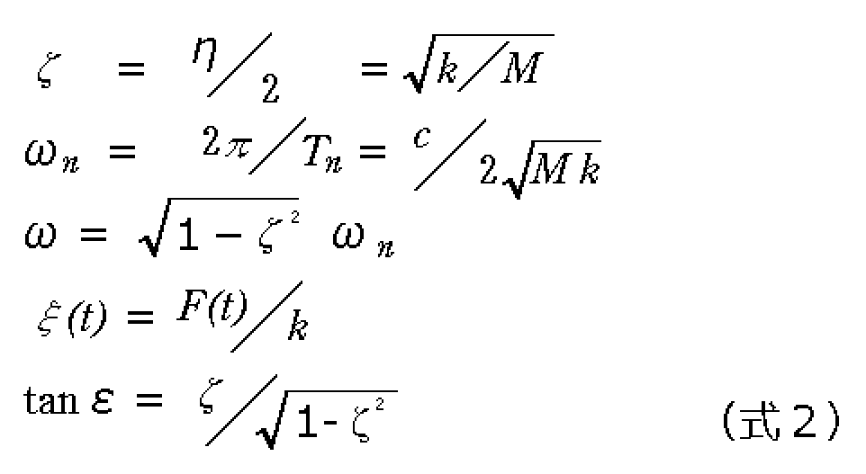


式2~式4において、Tnは防振用弾性体13,14の固有振動周期(二つの弾性体13,14の全体の固有振動周期)であり、ωnはその角振動数である。ここで、図3(2)に示すような台形制御のパターンを前提としてステージ3の停止を検討対象としてみると、外力F(t)はステージ3への制動力(ブレーキ)に対する駆動反力であるから、制動力が働き始めた時点から時刻τでゼロとなる。時刻τはステージ3への制動力がゼロになった時点であり、図2のシーケンスにおける減速部の終了時刻である。つまり、図3(2)に示すように、駆動反力F(t)による静荷重変位ξ(t)は、0≦t<τにおいてξpの値を有し、t≧τにおいて0の値を有する。この境界条件を前提にし、式4を解いてラプラス逆変換すると、以下の式5が得られる。
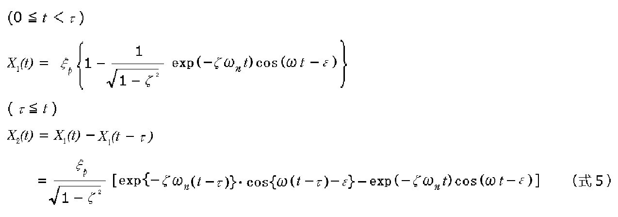
式2~式4において、Tnは防振用弾性体13,14の固有振動周期(二つの弾性体13,14の全体の固有振動周期)であり、ωnはその角振動数である。ここで、図3(2)に示すような台形制御のパターンを前提としてステージ3の停止を検討対象としてみると、外力F(t)はステージ3への制動力(ブレーキ)に対する駆動反力であるから、制動力が働き始めた時点から時刻τでゼロとなる。時刻τはステージ3への制動力がゼロになった時点であり、図2のシーケンスにおける減速部の終了時刻である。つまり、図3(2)に示すように、駆動反力F(t)による静荷重変位ξ(t)は、0≦t<τにおいてξpの値を有し、t≧τにおいて0の値を有する。この境界条件を前提にし、式4を解いてラプラス逆変換すると、以下の式5が得られる。
式5の運動方程式について、その一例をグラフ化したものが図4に示されている。図4は、実施形態のワーク搬送装置における駆動反力による構造体の振動波形の一例を示す図である。この例では、ζ=0.2、ωn=31.4rad/s、Tn=200ミリ秒とした。図4の横軸は、減速時間τで規格化した時間、縦軸は、駆動反力による静荷重変位ξpで規格した振幅である。図4には、τ=100ミリ秒、150ミリ秒、200ミリ秒の場合が示されている。
発明者は、この図4の解析結果をさらに検討した。図4において、t/τ=1の時点は、減速時間τが終了した時点である。したがって、その後の振動の最初のピーク(この例ではマイナス側に触れている)の大きさが問題となる。図4に示すように、この減速終了後の振動の最初のピークの値(以下、初期振動ピークという)は、減速時間τにより異なる。発明者は、初期振動ピークが減速時間τを変えていった場合にどのように異なるかを調べところ、周期的な変化をすることを見出した。そして、周期的な変化は、防振用弾性体13,14の固有振動周期Tnに依存することを突き止めた。
図5は、上記の点を示した図であり、図4の例をさらに解析した結果を示す図である。図5の縦軸は、静荷重変位ξpで規格化した初期ピークであり、横軸は防振用弾性体13,14の固有振動周期Tnで規格化した減速時間τである。図5に示すように、減速時間τが防振用弾性体13,14の固有振動周期Tnの自然数倍になっていると、初期振動ピークは極小値を持つ。
次に、S字制御を行う場合にどうなるかについて、発明者は解析を行ったので、その結果を説明する。図6は、S字制御における制動力を示す図である。また、図7は、図5と同様の図であり、S字制御の場合の減速時間τと初期ピークとの関係を示した図である。
図6に示すように、この解析では、同様に減速時を採り上げ、減速時間τにおいてちょうどの中間の時点でピークとなる制動力(いわゆる三角波)がステージ3に加わるとした。したがって、駆動反力の条件も同様であり、減速時間τの中間時点で静荷重変位がピーク値ξpとなる三角波形である。
図6に示すように、この解析では、同様に減速時を採り上げ、減速時間τにおいてちょうどの中間の時点でピークとなる制動力(いわゆる三角波)がステージ3に加わるとした。したがって、駆動反力の条件も同様であり、減速時間τの中間時点で静荷重変位がピーク値ξpとなる三角波形である。
図7は、以上を条件として同様の解析を行って初期ピークの減速時間依存性を調べた結果の図である。同様に、横軸は防振用弾性体13,14の固有振動周期Tnで規格化されており、縦軸は静荷重変位のピーク値ξpで規格化されている。図7に示すように、S字制御の場合、減速時間τが防振用弾性体13,14の固有振動周期Tnの2n倍(nは自然数)のとき、初期振動ピークは極小値を持つ。
以上の解析結果から判るように、実施形態のワーク搬送装置において、減速時間τが、台形制御の場合には防振用弾性体13,14の固有振動周期のn倍、S字制御の場合には2n倍であるとき、初期振動ピークは極小値となる。図4の解析結果から解る通り、初期振動ピークが小さい場合、振動が収まるまでの時間は短くなる。即ち、整定に要する時間が短くなる。
また、詳細な説明は割愛するが、加速についても加速時間を、台形制御の場合には防振用弾性体13,14の固有振動周期のn倍、S字制御の場合には2n倍にしておくと、初期振動ピークが小さくなり、整定に要する時間が短くできる。尚、加速については、定速部(設定搬送速度での移動)に達した時点から駆動反力による振動が始まり、定速部の動作中に振動が減衰する(振動が重畳した状態で移動する)ので、減速の場合ほどは影響が深刻ではない。即ち、減速部に達した時点では加速部により発生した振動は十分に減衰している場合もある。それでも、定速部の時間が短い場合には少なからず影響が出る可能性もあるので、上記のようにしておくことが好ましい。
この実施形態のワーク搬送装置は、以上の検討、解析を踏まえ、制御部5におけるシーケンスを最適化した構成となっている。具体的には、制御部5の記憶部51に記憶されたシーケンスプログラムは加速部と減速部とを有し、減速部の時間は、減速部の終了後のベース盤2の振動の最初のピークが最大値の半分以下となる時間となっている。また、当該シーケンスにおける加速部の時間は、加速部の終了後のベース盤2の振動の最初のピークが最大値の半分以下となる時間となっている。
より具体的には、台形制御の場合、減速部の時間及び加速部の時間は、防振用弾性体13,14の固有振動周期のn倍の値で設定され、S字制御の場合、防振用弾性体13,14の固有振動周期の2n倍の値で設定される。生産性を高くする観点から、nは小さい方が好ましく、1ないし2であることが好ましい。
より具体的には、台形制御の場合、減速部の時間及び加速部の時間は、防振用弾性体13,14の固有振動周期のn倍の値で設定され、S字制御の場合、防振用弾性体13,14の固有振動周期の2n倍の値で設定される。生産性を高くする観点から、nは小さい方が好ましく、1ないし2であることが好ましい。
上記減速時間及び加速時間の設定は当業者において容易であるが、台形制御の場合でn=1を例にすると、適当な設定搬送速度Vをまず定め、その設定搬送速度Vに対してTnとなる加速度を求める。防振用弾性体13,14の固有振動周期Tnは、防振台1の仕様で決まる値であり、いわゆるカタログ値である。そして、その加速度で設定搬送速度Vに達するまでの移動距離を2倍にし(減速も加速と同じ勾配)、必要な全体の移動距離から差し引いて残った距離が設定搬送速度Vでの移動距離ということになる。このようにして速度制御のシーケンスを策定した後、プログラムに組み込む。
尚、防振用弾性体13,14の固有振動周期は、0.1秒以上であることが好ましい。これは、前述したように、より防振効果を高めるためである。
尚、防振用弾性体13,14の固有振動周期は、0.1秒以上であることが好ましい。これは、前述したように、より防振効果を高めるためである。
制御部5は、ワークWの搬送に際してシーケンスプログラムを実行し、2nTn又はnTnの加速時間及び減速時間でステージ3を移動させる。減速部のシーケンスが終了した後、駆動反力でベース盤2が振動し、これと一体にステージ3も振動するが、加速時間及び減速時間が最適化されているので、短期間のうちに振動が収束し、整定に到達する。
次に、このような実施形態のワーク搬送装置の効果を確認した実験の結果について説明する。図8及び図9は、実施形態のワーク搬送装置の効果を確認した実験の結果を示した図である。図8は実施形態のワーク搬送装置についての結果、図9は参考例のワーク搬送装置についての結果を示す。
実施形態(図8)については、防振用弾性体の固有振動周期Tnを200ミリ秒とし、加速は台形制御、減速はS字制御とした。加速時間は200ミリ秒(=Tn)、減速時間は400ミリ秒(=2Tn)とした。図8(1)は、ステージ3の移動に伴うベース盤2の変位(計算値、実測値)を示しており、ステージ3の速度指令のパターンが併せて示されている。また、図8(2)には、図8(1)に示すベース盤2の変位が計測された際のステージ3の変位量の計測値が示されている。
実施形態(図8)については、防振用弾性体の固有振動周期Tnを200ミリ秒とし、加速は台形制御、減速はS字制御とした。加速時間は200ミリ秒(=Tn)、減速時間は400ミリ秒(=2Tn)とした。図8(1)は、ステージ3の移動に伴うベース盤2の変位(計算値、実測値)を示しており、ステージ3の速度指令のパターンが併せて示されている。また、図8(2)には、図8(1)に示すベース盤2の変位が計測された際のステージ3の変位量の計測値が示されている。
また、参考例(図9)については、防振用弾性体の固有振動周期Tnは同じく200ミリ秒とし、加速、減速ともS字制御とした、そして、加速時間は300ミリ秒(=1.5Tn)、減速時間も300ミリ秒(=1.5Tn)とした。
同様に、図9(1)は、参考例の装置において、ステージ3の移動に伴うベース盤2の変位量(計算値、実測値)がステージ3の速度指令のパターンとともに示されている。また、図9(2)には、図9(1)に示すベース盤2の変位が計測された際のステージ3の変位量の計測値が示されている。参考例では、ステージ3はY方向に移動する際にX方向にも変位しており、またθ方向にも変位していたので、それらの変位量も併せて示されている。
同様に、図9(1)は、参考例の装置において、ステージ3の移動に伴うベース盤2の変位量(計算値、実測値)がステージ3の速度指令のパターンとともに示されている。また、図9(2)には、図9(1)に示すベース盤2の変位が計測された際のステージ3の変位量の計測値が示されている。参考例では、ステージ3はY方向に移動する際にX方向にも変位しており、またθ方向にも変位していたので、それらの変位量も併せて示されている。
図8(1)に示すように、実施形態のワーク搬送装置で、減速部の終了後、ベース盤2の振動は速やかに収束している。そして、図8(2)に示すように、ステージ3は短時間に整定に達していることがわかる。
一方、図9(1)に示すように、参考例では、減速部の終了後、ベース盤2の振動は振幅が大きくそして長く続いている。そして、図9(2)に示すように、ステージ3は、減速部の終了後、Y方向のみならずX方向にもθ方向にも激しく振動しており、整定には長い時間を要していることがわかる。
一方、図9(1)に示すように、参考例では、減速部の終了後、ベース盤2の振動は振幅が大きくそして長く続いている。そして、図9(2)に示すように、ステージ3は、減速部の終了後、Y方向のみならずX方向にもθ方向にも激しく振動しており、整定には長い時間を要していることがわかる。
このような実施形態のワーク搬送装置が搭載された光照射装置の全体の動作について、以下に概略的に説明する。ワークWとしてのウエハは、AGV(Automated Guided vehicle)のような搬送装置により前工程から光照射装置に搬送される。ステージ3は予め所定のロード位置に待機している。ロード位置で、ロボット等のローディング機構が動作し、ワークWがステージ3に載置される。移動機構4はベース盤2上でステージ3を移動させ、ワークW内の最初のセグメントが照射領域Rに一致する位置でステージ3を停止させる。
この状態で、照射領域に対して照射光学系7により光照射がされる。その後、移動機構4が動作し、次のセグメントが照射領域に位置するようステージ3をX方向及び又はY方向に移動させる。そして、同様に光照射を繰り返す。
この状態で、照射領域に対して照射光学系7により光照射がされる。その後、移動機構4が動作し、次のセグメントが照射領域に位置するようステージ3をX方向及び又はY方向に移動させる。そして、同様に光照射を繰り返す。
このようにして逐次移動と光照射を繰り返し、一つのワークW内の全てのセグメントに光照射が完了すると当該ワークWの処理は終了である。尚、各セグメントは互いに隣接した領域であり、従って照射パターンで光照射された領域が互いに隣接した状態となる。一つのワークWに対する処理が終了すると、移動機構4はステージ3をロード位置に戻す。そして、処理済みのワークWがステージ3から取り去られ、次のワークWが載置され、同様のステップが繰り返される。
上述した光照射装置では、ワークWの各セグメントに光照射するためにステージ3は移動と停止を多数回繰り返すが、停止の際の整定に至るまでの時間が短いので、停止後に短時間のうちに光照射を開始できる。このため、一つのワークWに要する全体の処理時間が大幅に短くできる。特に、光照射装置が、1チップ領域内が多数のセグメントに区分けされて光照射される二光束干渉露光装置である場合、移動と停止の回数が非常に多くなるので、上記効果は著しい。
尚、上記のようなステップアンドリピートの光照射を行う場合、光照射はワークの表面(照射光学系の側の面)の全域に行われる場合がある。例えば光特許文献1に開示されているように、二光束干渉露光装置の用途として偏光板の一種であるグリッド偏光素子が検討されている。偏光作用を有するグリッドは、基板の一方の側の面に形成されたラインアンドスペースであり、当該面の全域に形成される。このため、全域に光照射がされる。
上記実施形態では、減速時間及び加速時間は、台形制御の場合にはnTn、S字制御の場合には2nTnであったが、図5や図7から解る通り、その前後の時間長であっても効果がある。即ち、S字制御の場合には、0より大きく1/2Tn以下、又は{(2n-1)+1/2}Tn以上(2n+1/2)Tn以下の時間であれば良く、台形制御の場合には0より大きく1/4Tn以下、又は{(n-1)+3/4}Tn以上(n+1/4)Tn以下の時間であれば良い。
また、ワーク搬送装置の用途としては、露光装置その他の光照射装置には限られず、ウエハ貼り合わせ装置のような光照射以外の処理をする装置に使用される場合もあり得る。
また、ワーク搬送装置の用途としては、露光装置その他の光照射装置には限られず、ウエハ貼り合わせ装置のような光照射以外の処理をする装置に使用される場合もあり得る。
尚、上記実施形態では、シーケンスはソフトウェアにより実装されるものであったが、ハードウェアにより実装される場合もありうる。
また、上記実施形態では、防振用弾性体13,14は、防振台1とベース盤2との間に介在するものであったが、防振用弾性体が防振台と床面との間に介在する場合もあり得る。この場合には、ベース盤が防振台に相当することになる。
尚、移動機構4はXY方向にステージ3を移動させるものであったが、本願発明の実施に際しては一方向にのみステージ3を移動させるものであっても良い。その場合、制御部は、移動距離のみを移動機構4に指示する場合があり得る。
また、上記実施形態では、防振用弾性体13,14は、防振台1とベース盤2との間に介在するものであったが、防振用弾性体が防振台と床面との間に介在する場合もあり得る。この場合には、ベース盤が防振台に相当することになる。
尚、移動機構4はXY方向にステージ3を移動させるものであったが、本願発明の実施に際しては一方向にのみステージ3を移動させるものであっても良い。その場合、制御部は、移動距離のみを移動機構4に指示する場合があり得る。
また、光照射装置や光照射方法の各発明の実施形態については、ステップアンドリピートを行う実施形態の他、ステージ3を移動させながらワークWに光照射する実施形態があり得る。このような場合にも、最終的なステージ3の停止位置の精度を高くしておくことは、処理の再現性の向上等の点で有益である場合が多く、本願発明の構成が好適に採用され得る。
1 防振台
13 防振用弾性体として防振ゴム
14 防振用弾性体としてのダンパー
2 ベース盤
3 ステージ
4 移動機構
5 制御部
51 記憶部
6 位置センサ
7 照射光学系
13 防振用弾性体として防振ゴム
14 防振用弾性体としてのダンパー
2 ベース盤
3 ステージ
4 移動機構
5 制御部
51 記憶部
6 位置センサ
7 照射光学系
Claims (26)
- 防振用弾性体を有する防振台と、
防振台の上に配置されたベース盤と、
ベース盤の上に配置され、ワークが載置されるステージと、
ステージを移動させることでワークを搬送する移動機構と、
移動機構を制御する制御部と
を備えており、
制御部は、移動機構によるステージの移動速度のシーケンスを実装しており、当該実装されたシーケンスでステージを移動させる制御信号を移動機構に送るものであり、
移動速度のシーケンスは、速度ゼロから設定搬送速度まで速度を上昇させる加速部と、設定搬送速度を維持する定速部と、設定搬送速度から速度ゼロまで速度を低下させる減速部とを有するシーケンスであり、
減速部の時間は、減速部の終了後の駆動反力によるベース盤の振動の最初のピークが防振用弾性体の固有振動周期との関係において最大値の半分以下となる時間であることを特徴とするワーク搬送装置。 - 前記加速部の時間は、前記加速部の終了後の駆動反力による前記ベース盤の振動の最初のピークが前記防振用弾性体の固有振動周期との関係において最大値の半分以下となる時間であることを特徴とする請求項1記載のワーク搬送装置。
- 前記加速部は、前記ステージの移動速度を線型的に上昇させるシーケンスであり、
前記減速部は、前記ステージの移動速度を線型的に低下させるシーケンスであり、
前記減速部の時間は、前記防振用弾性体の固有振動周期をTnとし、nを自然数としたとき、0より大きく1/4Tn以下、又は{(n-1)+3/4}Tn以上(n+1/4)Tn以下の時間であることを特徴とする請求項1又は2記載のワーク搬送装置。 - 前記加速部は、前記ステージの移動速度を線型的に上昇させるシーケンスであり、
前記減速部は、前記ステージの移動速度を線型的に低下させるシーケンスであり、
前記加速部の時間は、前記防振用弾性体の固有振動周期をTnとし、nを自然数としたとき、0より大きく1/4Tn以下、又は{(n-1)+3/4}Tn以上(n+1/4)Tn以下の時間であることを特徴とする請求項2記載のワーク搬送装置。 - 前記加速部は、前記ステージの移動速度を線型的に上昇させるシーケンスであり、
前記減速部は、前記ステージの移動速度を線型的に低下させるシーケンスであり、
前記減速部の時間は、nTnの時間であることを特徴とする請求項1又は2記載のワーク搬送装置。 - 前記加速部は、前記ステージの移動速度を線型的に上昇させるシーケンスであり、
前記減速部は、前記ステージの移動速度を線型的に低下させるシーケンスであり、
前記加速部の時間は、nTnの時間であることを特徴とする請求項2記載のワーク搬送装置。 - 前記加速部は、前記ステージの移動速度を非線型的に上昇させるシーケンスであり、
前記減速部は、前記ステージの移動速度を非線型的に低下させるシーケンスであり、
前記減速部の時間は、前記防振用弾性体の固有振動周期をTnとし、nを自然数としたとき、0より大きく1/2Tn以下、又は{(2n-1)+1/2}Tn以上(2n+1/2)Tn以下の時間であることを特徴とする請求項1又は2記載のワーク搬送装置。 - 前記加速部は、前記ステージの移動速度を非線型的に上昇させるシーケンスであり、
前記減速部は、前記ステージの移動速度を非線型的に低下させるシーケンスであり、
前記加速部の時間は、前記防振用弾性体の固有振動周期をTnとし、nを自然数としたとき、0より大きく1/2Tn以下、又は{(2n-1)+1/2}Tn以上(2n+1/2)Tn以下の時間であることを特徴とする請求項2記載のワーク搬送装置。 - 前記加速部は、前記ステージの移動速度を非線型的に上昇させるシーケンスであり、
前記減速部は、前記ステージの移動速度を非線型的に低下させるシーケンスであり、
前記減速部の時間は、2nTnの時間であることを特徴とする請求項1又は2記載のワーク搬送装置。 - 前記加速部は、前記ステージの移動速度を非線型的に上昇させるシーケンスであり、
前記減速部は、前記ステージの移動速度を非線型的に低下させるシーケンスであり、
前記加速部の時間は、2nTnの時間であることを特徴とする請求項2記載のワーク搬送装置。 - 前記防振用弾性体の固有振動周期は0.1秒以上であることを特徴とする請求項1乃至10いずれかに記載のワーク搬送装置。
- 請求項1乃至11いずれかに記載のワーク搬送装置と、
光源と、
光源からの光を前記ステージに載置されたワークに照射する照射光学系と
を備えた光照射装置であって、
照射光学系は、ワークよりも小さい照射パターンで光照射する光学系であり、
前記移動機構による移動距離は、当該照射パターンで光照射された領域がワーク上で隣接する距離として設定されており、
光源及び照射光学系は、前記ステージの停止中にワークに光照射するものであることを特徴とする光照射装置。 - 請求項1乃至11いずれかに記載のワーク搬送装置と、
光源と、
光源からの光を前記ステージに載置されたワークに照射する照射光学系と
を備えた光照射装置であって、
前記光源及び前記照射光学系は、前記移動機構による前記ステージの移動中にワークに光を照射するものであることを特徴とする光照射装置。 - 防振用弾性体を有する防振台と、
防振台の上に配置されたベース盤と、
ベース盤の上に配置されたステージと、
ステージを移動させることでワークを搬送する移動機構と、
移動機構を制御する制御部と
を備えたワーク搬送装置を使用してワークを搬送するワーク搬送方法であって、
ワークをステージに載置する載置ステップと、
ワークが載置されたステージを移動させることでワークを搬送する搬送ステップと
を有しており、
制御部は、移動機構によるステージの移動速度のシーケンスを実装しており、搬送ステップは、当該実装されたシーケンスでステージを移動させる制御信号を制御部が移動機構に送ることで搬送を行うステップであり、
移動速度のシーケンスは、速度ゼロから設定搬送速度まで速度を上昇させる加速部と、設定搬送速度を維持する定速部と、設定搬送速度から速度ゼロまで速度を低下させる減速部とを有するシーケンスであり、
減速部の時間は、減速部の終了後の駆動反力によるベース盤の振動の最初のピークが防振用弾性体の固有振動周期との関係において最大値の半分以下になる時間であることを特徴とするワーク搬送方法。 - 前記加速部の時間は、前記加速部の終了後の駆動反力によるベース盤の振動の最初のピークが前記防振用弾性体の固有振動周期との関係において、最大値の半分以下となる時間であることを特徴とする請求項14記載のワーク搬送方法。
- 前記加速部は、前記ステージの移動速度を線型的に上昇させるシーケンスであり、
前記減速部は、前記ステージの移動速度を線型的に低下させるシーケンスであり、
前記減速部の時間は、前記防振用弾性体の固有振動周期をTnとし、nを自然数としたとき、0より大きく1/4Tn以下、又は{(n-1)+3/4}Tn以上(n+1/4)Tn以下の時間であることを特徴とする請求項14又は15記載のワーク搬送方法。 - 前記加速部は、前記ステージの移動速度を線型的に上昇させるシーケンスであり、
前記減速部は、前記ステージの移動速度を線型的に低下させるシーケンスであり、
前記加速部の時間は、前記防振用弾性体の固有振動周期をTnとし、nを自然数としたとき、0より大きく1/4Tn以下、又は{(n-1)+3/4}Tn以上(n+1/4)Tn以下の時間であることを特徴とする請求項15記載のワーク搬送方法。 - 前記加速部は、前記ステージの移動速度を線型的に上昇させるシーケンスであり、
前記減速部は、前記ステージの移動速度を線型的に低下させるシーケンスであり、
前記減速部の時間は、nTnの時間であることを特徴とする請求項14又は15記載のワーク搬送方法。 - 前記加速部は、前記ステージの移動速度を線型的に上昇させるシーケンスであり、
前記減速部は、前記ステージの移動速度を線型的に低下させるシーケンスであり、
前記加速部の時間は、nTnの時間であることを特徴とする請求項15記載のワーク搬送方法。 - 前記加速部は、前記ステージの移動速度を非線型的に上昇させるシーケンスであり、
前記減速部は、前記ステージの移動速度を非線型的に低下させるシーケンスであり、
前記減速部の時間は、前記防振用弾性体の固有振動周期をTnとし、nを自然数としたとき、0より大きく1/2Tn以下、又は{(2n-1)+1/2}Tn以上(2n+1/2)Tn以下の時間であることを特徴とする請求項14又は15記載のワーク搬送方法。 - 前記加速部は、前記ステージの移動速度を非線型的に上昇させるシーケンスであり、
前記減速部は、前記ステージの移動速度を非線型的に低下させるシーケンスであり、
前記加速部の時間は、前記防振用弾性体の固有振動周期をTnとし、nを自然数としたとき、0より大きく1/2Tn以下、又は{(2n-1)+1/2}Tn以上(2n+1/2)Tn以下の時間であることを特徴とする請求項15記載のワーク搬送方法。 - 前記加速部は、前記ステージの移動速度を非線型的に上昇させるシーケンスであり、
前記減速部は、前記ステージの移動速度を非線型的に低下させるシーケンスであり、
前記減速部の時間は、2nTnの時間であることを特徴とする請求項14又は15記載のワーク搬送方法。 - 前記加速部は、前記ステージの移動速度を非線型的に上昇させるシーケンスであり、
前記減速部は、前記ステージの移動速度を非線型的に低下させるシーケンスであり、
前記加速部の時間は、2nTnの時間であることを特徴とする請求項15記載のワーク搬送方法。 - 前記防振用弾性体の固有振動周期は0.1秒以上であることを特徴とする請求項14乃至23いずれかに記載のワーク搬送方法。
- 請求項1乃至11いずれかに記載のワーク搬送装置を使用してワークに光照射する光照射方法であって、
前記ステージが停止している際に前記ステージに載置されたワークに対し、光源からの光を当該ワークよりも小さい照射パターンで照射する照射ステップと、
前記移動機構を動作させてワークを搬送する搬送ステップとを繰り返す光照射方法であり、
各照射ステップで光照射された領域がワーク上で隣接することを特徴とする光照射方法。 - 請求項1乃至11いずれかに記載のワーク搬送装置を使用してワークに光照射する光照射方法であって、
前記ステージが前記移動機構により移動している際に前記ステージに載置されたワークに対して光源からの光を照射することを特徴とする光照射方法。
Applications Claiming Priority (2)
| Application Number | Priority Date | Filing Date | Title |
|---|---|---|---|
| JP2016073277A JP6665639B2 (ja) | 2016-03-31 | 2016-03-31 | ワーク搬送装置、光照射装置、ワーク搬送方法及び光照射方法 |
| JP2016-073277 | 2016-03-31 |
Publications (1)
| Publication Number | Publication Date |
|---|---|
| WO2017169404A1 true WO2017169404A1 (ja) | 2017-10-05 |
Family
ID=59963138
Family Applications (1)
| Application Number | Title | Priority Date | Filing Date |
|---|---|---|---|
| PCT/JP2017/007247 Ceased WO2017169404A1 (ja) | 2016-03-31 | 2017-02-24 | ワーク搬送装置、光照射装置、ワーク搬送方法及び光照射方法 |
Country Status (2)
| Country | Link |
|---|---|
| JP (1) | JP6665639B2 (ja) |
| WO (1) | WO2017169404A1 (ja) |
Citations (8)
| Publication number | Priority date | Publication date | Assignee | Title |
|---|---|---|---|---|
| JPS59182524A (ja) * | 1983-03-31 | 1984-10-17 | Jeol Ltd | ステ−ジ移動方法 |
| JPS6363988A (ja) * | 1986-09-04 | 1988-03-22 | オムロン株式会社 | 位置決めステ−ジ機構の駆動方法 |
| JP2002329771A (ja) * | 2001-04-26 | 2002-11-15 | Kyocera Corp | ステージ装置 |
| JP2003241838A (ja) * | 2002-02-20 | 2003-08-29 | Japan Science & Technology Corp | 位置決め装置 |
| JP2005026504A (ja) * | 2003-07-03 | 2005-01-27 | Nikon Corp | ステージ装置、露光装置及び制御方法 |
| JP2009181395A (ja) * | 2008-01-31 | 2009-08-13 | Panasonic Corp | ロボットの制御方法、ロボットの制御装置及び部品実装機 |
| JP2011164680A (ja) * | 2010-02-04 | 2011-08-25 | Fuji Electric Co Ltd | 位置指令生成器 |
| JP2014056352A (ja) * | 2012-09-11 | 2014-03-27 | Canon Inc | 位置決め装置及び計測装置 |
-
2016
- 2016-03-31 JP JP2016073277A patent/JP6665639B2/ja active Active
-
2017
- 2017-02-24 WO PCT/JP2017/007247 patent/WO2017169404A1/ja not_active Ceased
Patent Citations (8)
| Publication number | Priority date | Publication date | Assignee | Title |
|---|---|---|---|---|
| JPS59182524A (ja) * | 1983-03-31 | 1984-10-17 | Jeol Ltd | ステ−ジ移動方法 |
| JPS6363988A (ja) * | 1986-09-04 | 1988-03-22 | オムロン株式会社 | 位置決めステ−ジ機構の駆動方法 |
| JP2002329771A (ja) * | 2001-04-26 | 2002-11-15 | Kyocera Corp | ステージ装置 |
| JP2003241838A (ja) * | 2002-02-20 | 2003-08-29 | Japan Science & Technology Corp | 位置決め装置 |
| JP2005026504A (ja) * | 2003-07-03 | 2005-01-27 | Nikon Corp | ステージ装置、露光装置及び制御方法 |
| JP2009181395A (ja) * | 2008-01-31 | 2009-08-13 | Panasonic Corp | ロボットの制御方法、ロボットの制御装置及び部品実装機 |
| JP2011164680A (ja) * | 2010-02-04 | 2011-08-25 | Fuji Electric Co Ltd | 位置指令生成器 |
| JP2014056352A (ja) * | 2012-09-11 | 2014-03-27 | Canon Inc | 位置決め装置及び計測装置 |
Also Published As
| Publication number | Publication date |
|---|---|
| JP6665639B2 (ja) | 2020-03-13 |
| JP2017182000A (ja) | 2017-10-05 |
Similar Documents
| Publication | Publication Date | Title |
|---|---|---|
| US10808790B2 (en) | Vibration isolation system | |
| KR20030076275A (ko) | 케이블 항력이 스테이지에 작용하는 것을 방지할 수 있는위치결정 시스템과 스테이지 시스템, 및 케이블 항력이스테이지에 작용하는 것을 방지하는 방법 | |
| JP6218459B2 (ja) | 除振装置、除振方法、リソグラフィ装置及びデバイスの製造方法 | |
| WO2018020625A1 (ja) | 荷電粒子線装置 | |
| TWI234333B (en) | Vibration control device | |
| IL272694B2 (en) | Electron beam inspection apparatus stage positioning | |
| JP6307101B2 (ja) | リソグラフィ装置、および物品の製造方法 | |
| JP6665639B2 (ja) | ワーク搬送装置、光照射装置、ワーク搬送方法及び光照射方法 | |
| JP6333081B2 (ja) | 振動制御装置、リソグラフィ装置、および物品の製造方法 | |
| JP2023001194A (ja) | 荷電粒子ビーム描画装置 | |
| EP3385792A2 (en) | Stage apparatus for use in a lithographic apparatus | |
| JP5473575B2 (ja) | 露光装置及びデバイス製造方法 | |
| KR100659479B1 (ko) | 스테이지 장치용 반력 처리 시스템 | |
| JP3121528B2 (ja) | 振動検出装置および振動検出方法 | |
| JP5649063B2 (ja) | 制御方法、プログラム、記録媒体、及び、制御装置 | |
| CN120019287A (zh) | 用于测量或加工镜片的设备和运行方法 | |
| Hwang et al. | Input-shaping methods for a linear motor motion stage with a passive RFC (reaction force compensation) Mechanism | |
| JPH03107639A (ja) | 振動防止型位置決め装置 | |
| JP5090392B2 (ja) | ステージ装置 | |
| CN117859101A (zh) | 物体夹持器、保持物体的方法以及光刻设备 | |
| Seo et al. | Reaction Force Compensator for High‐Speed Precision Stage of Laser Direct Imaging Process | |
| CN111566379B (zh) | 主动隔振装置 | |
| JP2007188251A (ja) | ステージ装置 | |
| WO2017085840A1 (ja) | 部品実装関連装置及びその設置方法 | |
| WO2020173641A1 (en) | Inspection apparatus, lithographic apparatus, measurement method |
Legal Events
| Date | Code | Title | Description |
|---|---|---|---|
| NENP | Non-entry into the national phase |
Ref country code: DE |
|
| 121 | Ep: the epo has been informed by wipo that ep was designated in this application |
Ref document number: 17773949 Country of ref document: EP Kind code of ref document: A1 |
|
| 122 | Ep: pct application non-entry in european phase |
Ref document number: 17773949 Country of ref document: EP Kind code of ref document: A1 |