WO2017169240A1 - 遺伝子解析方法 - Google Patents
遺伝子解析方法 Download PDFInfo
- Publication number
- WO2017169240A1 WO2017169240A1 PCT/JP2017/005634 JP2017005634W WO2017169240A1 WO 2017169240 A1 WO2017169240 A1 WO 2017169240A1 JP 2017005634 W JP2017005634 W JP 2017005634W WO 2017169240 A1 WO2017169240 A1 WO 2017169240A1
- Authority
- WO
- WIPO (PCT)
- Prior art keywords
- information
- cells
- container
- cell
- analysis
- Prior art date
Links
- 238000000034 method Methods 0.000 title claims abstract description 111
- 238000012252 genetic analysis Methods 0.000 title claims abstract description 8
- 238000004458 analytical method Methods 0.000 claims abstract description 78
- 238000000605 extraction Methods 0.000 claims abstract description 62
- 230000003321 amplification Effects 0.000 claims abstract description 49
- 238000003199 nucleic acid amplification method Methods 0.000 claims abstract description 49
- 238000010186 staining Methods 0.000 claims abstract description 22
- 238000000684 flow cytometry Methods 0.000 claims abstract description 19
- 239000012488 sample solution Substances 0.000 claims abstract description 17
- 238000003384 imaging method Methods 0.000 claims description 44
- 108090000623 proteins and genes Proteins 0.000 claims description 38
- 238000012744 immunostaining Methods 0.000 claims description 22
- 238000006243 chemical reaction Methods 0.000 claims description 11
- 238000003752 polymerase chain reaction Methods 0.000 claims description 5
- 238000000018 DNA microarray Methods 0.000 claims description 4
- 238000007847 digital PCR Methods 0.000 claims description 4
- 238000005194 fractionation Methods 0.000 claims description 3
- 238000003753 real-time PCR Methods 0.000 claims description 3
- 239000002904 solvent Substances 0.000 claims description 3
- 210000004027 cell Anatomy 0.000 description 182
- 210000003743 erythrocyte Anatomy 0.000 description 44
- 238000000926 separation method Methods 0.000 description 41
- 108020004414 DNA Proteins 0.000 description 24
- 230000005284 excitation Effects 0.000 description 20
- CIWBSHSKHKDKBQ-JLAZNSOCSA-N Ascorbic acid Chemical compound OC[C@H](O)[C@H]1OC(=O)C(O)=C1O CIWBSHSKHKDKBQ-JLAZNSOCSA-N 0.000 description 19
- 239000007850 fluorescent dye Substances 0.000 description 11
- 238000000432 density-gradient centrifugation Methods 0.000 description 9
- 210000004369 blood Anatomy 0.000 description 8
- 239000008280 blood Substances 0.000 description 8
- 230000001605 fetal effect Effects 0.000 description 8
- 239000000523 sample Substances 0.000 description 8
- 230000008774 maternal effect Effects 0.000 description 7
- 102000053602 DNA Human genes 0.000 description 6
- 230000004544 DNA amplification Effects 0.000 description 6
- 210000000601 blood cell Anatomy 0.000 description 6
- 238000010586 diagram Methods 0.000 description 5
- 239000000428 dust Substances 0.000 description 5
- 102100037422 Receptor-type tyrosine-protein phosphatase C Human genes 0.000 description 4
- FAPWRFPIFSIZLT-UHFFFAOYSA-M Sodium chloride Chemical compound [Na+].[Cl-] FAPWRFPIFSIZLT-UHFFFAOYSA-M 0.000 description 4
- 239000000427 antigen Substances 0.000 description 4
- 108091007433 antigens Proteins 0.000 description 4
- 102000036639 antigens Human genes 0.000 description 4
- 238000005119 centrifugation Methods 0.000 description 4
- 239000003085 diluting agent Substances 0.000 description 4
- 210000003754 fetus Anatomy 0.000 description 4
- MHMNJMPURVTYEJ-UHFFFAOYSA-N fluorescein-5-isothiocyanate Chemical compound O1C(=O)C2=CC(N=C=S)=CC=C2C21C1=CC=C(O)C=C1OC1=CC(O)=CC=C21 MHMNJMPURVTYEJ-UHFFFAOYSA-N 0.000 description 4
- 239000007788 liquid Substances 0.000 description 4
- 210000004940 nucleus Anatomy 0.000 description 4
- 102000016928 DNA-directed DNA polymerase Human genes 0.000 description 3
- 108010014303 DNA-directed DNA polymerase Proteins 0.000 description 3
- 101000738771 Homo sapiens Receptor-type tyrosine-protein phosphatase C Proteins 0.000 description 3
- 108020004682 Single-Stranded DNA Proteins 0.000 description 3
- 230000000295 complement effect Effects 0.000 description 3
- 239000012634 fragment Substances 0.000 description 3
- 210000004698 lymphocyte Anatomy 0.000 description 3
- 210000005259 peripheral blood Anatomy 0.000 description 3
- 239000011886 peripheral blood Substances 0.000 description 3
- FWBHETKCLVMNFS-UHFFFAOYSA-N 4',6-Diamino-2-phenylindol Chemical compound C1=CC(C(=N)N)=CC=C1C1=CC2=CC=C(C(N)=N)C=C2N1 FWBHETKCLVMNFS-UHFFFAOYSA-N 0.000 description 2
- YXHLJMWYDTXDHS-IRFLANFNSA-N 7-aminoactinomycin D Chemical compound C[C@H]1OC(=O)[C@H](C(C)C)N(C)C(=O)CN(C)C(=O)[C@@H]2CCCN2C(=O)[C@@H](C(C)C)NC(=O)[C@H]1NC(=O)C1=C(N)C(=O)C(C)=C2OC(C(C)=C(N)C=C3C(=O)N[C@@H]4C(=O)N[C@@H](C(N5CCC[C@H]5C(=O)N(C)CC(=O)N(C)[C@@H](C(C)C)C(=O)O[C@@H]4C)=O)C(C)C)=C3N=C21 YXHLJMWYDTXDHS-IRFLANFNSA-N 0.000 description 2
- 108700012813 7-aminoactinomycin D Proteins 0.000 description 2
- 101000835093 Homo sapiens Transferrin receptor protein 1 Proteins 0.000 description 2
- 108010004729 Phycoerythrin Proteins 0.000 description 2
- 102100026144 Transferrin receptor protein 1 Human genes 0.000 description 2
- 238000001514 detection method Methods 0.000 description 2
- 238000004043 dyeing Methods 0.000 description 2
- 230000000694 effects Effects 0.000 description 2
- 238000001962 electrophoresis Methods 0.000 description 2
- 238000001943 fluorescence-activated cell sorting Methods 0.000 description 2
- 230000002068 genetic effect Effects 0.000 description 2
- 238000002826 magnetic-activated cell sorting Methods 0.000 description 2
- 238000002156 mixing Methods 0.000 description 2
- 210000000440 neutrophil Anatomy 0.000 description 2
- 210000003924 normoblast Anatomy 0.000 description 2
- XJMOSONTPMZWPB-UHFFFAOYSA-M propidium iodide Chemical compound [I-].[I-].C12=CC(N)=CC=C2C2=CC=C(N)C=C2[N+](CCC[N+](C)(CC)CC)=C1C1=CC=CC=C1 XJMOSONTPMZWPB-UHFFFAOYSA-M 0.000 description 2
- 239000011780 sodium chloride Substances 0.000 description 2
- PRDFBSVERLRRMY-UHFFFAOYSA-N 2'-(4-ethoxyphenyl)-5-(4-methylpiperazin-1-yl)-2,5'-bibenzimidazole Chemical compound C1=CC(OCC)=CC=C1C1=NC2=CC=C(C=3NC4=CC(=CC=C4N=3)N3CCN(C)CC3)C=C2N1 PRDFBSVERLRRMY-UHFFFAOYSA-N 0.000 description 1
- 108091093088 Amplicon Proteins 0.000 description 1
- 210000003771 C cell Anatomy 0.000 description 1
- 208000031404 Chromosome Aberrations Diseases 0.000 description 1
- 102000012410 DNA Ligases Human genes 0.000 description 1
- 108010061982 DNA Ligases Proteins 0.000 description 1
- 230000006820 DNA synthesis Effects 0.000 description 1
- 229920001917 Ficoll Polymers 0.000 description 1
- 206010064571 Gene mutation Diseases 0.000 description 1
- 108090001090 Lectins Proteins 0.000 description 1
- 102000004856 Lectins Human genes 0.000 description 1
- 108010013709 Leukocyte Common Antigens Proteins 0.000 description 1
- 108091028043 Nucleic acid sequence Proteins 0.000 description 1
- CZMRCDWAGMRECN-UGDNZRGBSA-N Sucrose Chemical compound O[C@H]1[C@H](O)[C@@H](CO)O[C@@]1(CO)O[C@@H]1[C@H](O)[C@@H](O)[C@H](O)[C@@H](CO)O1 CZMRCDWAGMRECN-UGDNZRGBSA-N 0.000 description 1
- 229930006000 Sucrose Natural products 0.000 description 1
- 239000002253 acid Substances 0.000 description 1
- 239000011543 agarose gel Substances 0.000 description 1
- 210000003651 basophil Anatomy 0.000 description 1
- 230000015572 biosynthetic process Effects 0.000 description 1
- 210000000349 chromosome Anatomy 0.000 description 1
- 239000012141 concentrate Substances 0.000 description 1
- RGWHQCVHVJXOKC-SHYZEUOFSA-N dCTP Chemical compound O=C1N=C(N)C=CN1[C@@H]1O[C@H](CO[P@](O)(=O)O[P@](O)(=O)OP(O)(O)=O)[C@@H](O)C1 RGWHQCVHVJXOKC-SHYZEUOFSA-N 0.000 description 1
- 239000000975 dye Substances 0.000 description 1
- 210000003979 eosinophil Anatomy 0.000 description 1
- 238000001914 filtration Methods 0.000 description 1
- 239000012530 fluid Substances 0.000 description 1
- 210000003714 granulocyte Anatomy 0.000 description 1
- 230000005484 gravity Effects 0.000 description 1
- 229910052736 halogen Inorganic materials 0.000 description 1
- 150000002367 halogens Chemical class 0.000 description 1
- 238000010438 heat treatment Methods 0.000 description 1
- 229920001477 hydrophilic polymer Polymers 0.000 description 1
- 238000011534 incubation Methods 0.000 description 1
- 230000000366 juvenile effect Effects 0.000 description 1
- 238000010030 laminating Methods 0.000 description 1
- 239000002523 lectin Substances 0.000 description 1
- 210000000265 leukocyte Anatomy 0.000 description 1
- 239000000463 material Substances 0.000 description 1
- 238000005259 measurement Methods 0.000 description 1
- QSHDDOUJBYECFT-UHFFFAOYSA-N mercury Chemical compound [Hg] QSHDDOUJBYECFT-UHFFFAOYSA-N 0.000 description 1
- 229910052753 mercury Inorganic materials 0.000 description 1
- 238000012986 modification Methods 0.000 description 1
- 230000004048 modification Effects 0.000 description 1
- 210000001616 monocyte Anatomy 0.000 description 1
- 210000005087 mononuclear cell Anatomy 0.000 description 1
- 230000007935 neutral effect Effects 0.000 description 1
- 230000003204 osmotic effect Effects 0.000 description 1
- 102000054765 polymorphisms of proteins Human genes 0.000 description 1
- 239000001267 polyvinylpyrrolidone Substances 0.000 description 1
- 235000013855 polyvinylpyrrolidone Nutrition 0.000 description 1
- 229920000036 polyvinylpyrrolidone Polymers 0.000 description 1
- 238000002360 preparation method Methods 0.000 description 1
- INCIMLINXXICKS-UHFFFAOYSA-M pyronin Y Chemical compound [Cl-].C1=CC(=[N+](C)C)C=C2OC3=CC(N(C)C)=CC=C3C=C21 INCIMLINXXICKS-UHFFFAOYSA-M 0.000 description 1
- RMAQACBXLXPBSY-UHFFFAOYSA-N silicic acid Chemical compound O[Si](O)(O)O RMAQACBXLXPBSY-UHFFFAOYSA-N 0.000 description 1
- ZEYOIOAKZLALAP-UHFFFAOYSA-M sodium amidotrizoate Chemical compound [Na+].CC(=O)NC1=C(I)C(NC(C)=O)=C(I)C(C([O-])=O)=C1I ZEYOIOAKZLALAP-UHFFFAOYSA-M 0.000 description 1
- 239000000126 substance Substances 0.000 description 1
- 239000000758 substrate Substances 0.000 description 1
- -1 succinimidyl ester Chemical class 0.000 description 1
- 239000005720 sucrose Substances 0.000 description 1
- 238000003786 synthesis reaction Methods 0.000 description 1
- MPLHNVLQVRSVEE-UHFFFAOYSA-N texas red Chemical compound [O-]S(=O)(=O)C1=CC(S(Cl)(=O)=O)=CC=C1C(C1=CC=2CCCN3CCCC(C=23)=C1O1)=C2C1=C(CCC1)C3=[N+]1CCCC3=C2 MPLHNVLQVRSVEE-UHFFFAOYSA-N 0.000 description 1
- WFKWXMTUELFFGS-UHFFFAOYSA-N tungsten Chemical compound [W] WFKWXMTUELFFGS-UHFFFAOYSA-N 0.000 description 1
- 229910052721 tungsten Inorganic materials 0.000 description 1
- 239000010937 tungsten Substances 0.000 description 1
- 229910052724 xenon Inorganic materials 0.000 description 1
- FHNFHKCVQCLJFQ-UHFFFAOYSA-N xenon atom Chemical compound [Xe] FHNFHKCVQCLJFQ-UHFFFAOYSA-N 0.000 description 1
Images


Classifications
-
- G—PHYSICS
- G01—MEASURING; TESTING
- G01N—INVESTIGATING OR ANALYSING MATERIALS BY DETERMINING THEIR CHEMICAL OR PHYSICAL PROPERTIES
- G01N15/00—Investigating characteristics of particles; Investigating permeability, pore-volume, or surface-area of porous materials
- G01N15/10—Investigating individual particles
- G01N15/14—Electro-optical investigation, e.g. flow cytometers
-
- C—CHEMISTRY; METALLURGY
- C12—BIOCHEMISTRY; BEER; SPIRITS; WINE; VINEGAR; MICROBIOLOGY; ENZYMOLOGY; MUTATION OR GENETIC ENGINEERING
- C12Q—MEASURING OR TESTING PROCESSES INVOLVING ENZYMES, NUCLEIC ACIDS OR MICROORGANISMS; COMPOSITIONS OR TEST PAPERS THEREFOR; PROCESSES OF PREPARING SUCH COMPOSITIONS; CONDITION-RESPONSIVE CONTROL IN MICROBIOLOGICAL OR ENZYMOLOGICAL PROCESSES
- C12Q1/00—Measuring or testing processes involving enzymes, nucleic acids or microorganisms; Compositions therefor; Processes of preparing such compositions
- C12Q1/68—Measuring or testing processes involving enzymes, nucleic acids or microorganisms; Compositions therefor; Processes of preparing such compositions involving nucleic acids
- C12Q1/6806—Preparing nucleic acids for analysis, e.g. for polymerase chain reaction [PCR] assay
-
- G—PHYSICS
- G01—MEASURING; TESTING
- G01N—INVESTIGATING OR ANALYSING MATERIALS BY DETERMINING THEIR CHEMICAL OR PHYSICAL PROPERTIES
- G01N15/00—Investigating characteristics of particles; Investigating permeability, pore-volume, or surface-area of porous materials
- G01N15/10—Investigating individual particles
- G01N15/14—Electro-optical investigation, e.g. flow cytometers
- G01N15/1429—Electro-optical investigation, e.g. flow cytometers using an analyser being characterised by its signal processing
-
- G—PHYSICS
- G01—MEASURING; TESTING
- G01N—INVESTIGATING OR ANALYSING MATERIALS BY DETERMINING THEIR CHEMICAL OR PHYSICAL PROPERTIES
- G01N15/00—Investigating characteristics of particles; Investigating permeability, pore-volume, or surface-area of porous materials
- G01N15/10—Investigating individual particles
- G01N15/14—Electro-optical investigation, e.g. flow cytometers
- G01N15/1456—Electro-optical investigation, e.g. flow cytometers without spatial resolution of the texture or inner structure of the particle, e.g. processing of pulse signals
- G01N15/1459—Electro-optical investigation, e.g. flow cytometers without spatial resolution of the texture or inner structure of the particle, e.g. processing of pulse signals the analysis being performed on a sample stream
-
- G—PHYSICS
- G01—MEASURING; TESTING
- G01N—INVESTIGATING OR ANALYSING MATERIALS BY DETERMINING THEIR CHEMICAL OR PHYSICAL PROPERTIES
- G01N15/00—Investigating characteristics of particles; Investigating permeability, pore-volume, or surface-area of porous materials
- G01N15/10—Investigating individual particles
- G01N15/14—Electro-optical investigation, e.g. flow cytometers
- G01N15/1468—Electro-optical investigation, e.g. flow cytometers with spatial resolution of the texture or inner structure of the particle
-
- C—CHEMISTRY; METALLURGY
- C12—BIOCHEMISTRY; BEER; SPIRITS; WINE; VINEGAR; MICROBIOLOGY; ENZYMOLOGY; MUTATION OR GENETIC ENGINEERING
- C12Q—MEASURING OR TESTING PROCESSES INVOLVING ENZYMES, NUCLEIC ACIDS OR MICROORGANISMS; COMPOSITIONS OR TEST PAPERS THEREFOR; PROCESSES OF PREPARING SUCH COMPOSITIONS; CONDITION-RESPONSIVE CONTROL IN MICROBIOLOGICAL OR ENZYMOLOGICAL PROCESSES
- C12Q1/00—Measuring or testing processes involving enzymes, nucleic acids or microorganisms; Compositions therefor; Processes of preparing such compositions
- C12Q1/68—Measuring or testing processes involving enzymes, nucleic acids or microorganisms; Compositions therefor; Processes of preparing such compositions involving nucleic acids
- C12Q1/6813—Hybridisation assays
- C12Q1/6816—Hybridisation assays characterised by the detection means
- C12Q1/6825—Nucleic acid detection involving sensors
-
- C—CHEMISTRY; METALLURGY
- C12—BIOCHEMISTRY; BEER; SPIRITS; WINE; VINEGAR; MICROBIOLOGY; ENZYMOLOGY; MUTATION OR GENETIC ENGINEERING
- C12Q—MEASURING OR TESTING PROCESSES INVOLVING ENZYMES, NUCLEIC ACIDS OR MICROORGANISMS; COMPOSITIONS OR TEST PAPERS THEREFOR; PROCESSES OF PREPARING SUCH COMPOSITIONS; CONDITION-RESPONSIVE CONTROL IN MICROBIOLOGICAL OR ENZYMOLOGICAL PROCESSES
- C12Q1/00—Measuring or testing processes involving enzymes, nucleic acids or microorganisms; Compositions therefor; Processes of preparing such compositions
- C12Q1/68—Measuring or testing processes involving enzymes, nucleic acids or microorganisms; Compositions therefor; Processes of preparing such compositions involving nucleic acids
- C12Q1/6844—Nucleic acid amplification reactions
- C12Q1/686—Polymerase chain reaction [PCR]
-
- G01N15/149—
-
- G—PHYSICS
- G01—MEASURING; TESTING
- G01N—INVESTIGATING OR ANALYSING MATERIALS BY DETERMINING THEIR CHEMICAL OR PHYSICAL PROPERTIES
- G01N15/00—Investigating characteristics of particles; Investigating permeability, pore-volume, or surface-area of porous materials
- G01N15/10—Investigating individual particles
- G01N2015/1006—Investigating individual particles for cytology
Definitions
- the present invention relates to a gene analysis method.
- Patent Document 1 uses a sorting function of a flow cytometer (an apparatus used in a flow cytometry method) for a minute cell (micronucleus) that is caused by a chromosomal abnormality and from which a part of the cell is separated. It is described that the main nucleus (parent nucleus) and the small nucleus are separated and recovered.
- cells are sorted by obtaining information on forward scattered light, side scattered light, and fluorescence intensity from cells, and target cells are placed in a container having a plurality of wells. Sorting is done.
- the container in which the cells are collected is set in a PCR (Polymerase® Chain® Reaction) apparatus, DNA (Deoxyribonucleic® Acid) is amplified, and gene analysis is performed.
- PCR Polymerase® Chain® Reaction
- nucleated red blood cells can be sorted by flow cytometry, but it has been difficult to sort nucleated red blood cells into maternally-derived nucleated red blood cells and fetal-derived nucleated red blood cells.
- the present invention has been made in view of such circumstances, and an object thereof is to provide a highly reliable gene analysis method using a flow cytometry method.
- the gene analysis method obtains first information derived from cells of a sample solution by a staining step for staining cells and a flow cytometry method, and analyzes the first information according to the determined extraction conditions. Then, from the result of the analysis, a target cell is sorted into a container in which a plurality of wells are arranged, an amplification process for amplifying the DNA of the cell sorted in the container, and the amplified DNA as a gene An analysis step for analysis, and a condition determination step for re-determining the extraction condition based on at least one information of the second information acquired in the amplification step and the third information acquired in the analysis step.
- the cell staining is immunostaining by antigen-antibody reaction.
- the first information is information on at least one of fluorescence emission by immunostaining, forward scattered light, and side scattered light.
- an imaging step of imaging the cells sorted in the container is provided between the sorting step and the amplification step, and the extraction condition is redetermined based on the fourth information acquired in the imaging step.
- the fourth information includes at least one of fluorescence intensity, shape, color, and size of the cell.
- the second information includes the presence or absence of DNA amplification
- the third information includes the presence or absence of the target cell.
- the amplification step includes a polymerase chain reaction.
- the gene analysis is selected from the group consisting of a DNA microarray method, a digital PCR method, a real-time PCR method, a sequencer method, and combinations thereof.
- a concentration step for increasing the concentration of cells in the solvent is provided before the staining step.
- the gene analysis method includes a step of staining a cell, obtains first information derived from the cells of the sample solution by flow cytometry, and analyzes the first information according to the determined extraction conditions. Then, from the analysis results, the target cells are sorted into a container in which a plurality of wells are arranged, the imaging process for imaging the cells sorted in the container, and the cells sorted in the container An amplification step for amplifying DNA, an analysis step for genetic analysis of the amplified DNA, second information acquired in the amplification step, third information acquired in the analysis step, and fourth information acquired in the imaging step And a condition determining step for re-determining the extraction condition based on at least one piece of information.
- FIG. 6 is a scattergram after re-determining extraction conditions based on the second information of the amplification process with respect to the scattergram of FIG. 5.
- FIG. 9 is a scattergram after re-determining the extraction conditions based on the third information in the analysis step with respect to the scattergram of FIG. 8. It is the flowchart which showed the procedure of the gene-analysis method of 2nd Embodiment. It is a schematic block diagram of an image pick-up device.
- FIG. 6 is a scattergram after re-determining the extraction condition based on the fourth information of the imaging process with respect to the scattergram of FIG. 5. It is a scattergram after re-determining extraction conditions based on the 2nd information of an amplification process to the scattergram of Drawing 12.
- FIG. 1 is a flowchart of the gene analysis method of the first embodiment.
- the gene analysis method includes a staining process (step S1), a sorting process (step S2), an amplification process (step S3), an analysis process (step S4), and a condition determination process (step S5). At least.
- step S1 the cells are stained.
- step S2 the first information derived from the cells of the sample solution is obtained by flow cytometry, the first information is analyzed according to the determined extraction conditions, and a plurality of target cells are determined from the analysis results. Aliquot into wells with wells arranged.
- step S3 the DNA of the cells sorted in the container is amplified.
- step S4 the amplified DNA is genetically analyzed.
- step S5 the extraction condition is redetermined based on at least one of the second information acquired in the amplification step and the third information acquired in the analysis step.
- step S1 In this embodiment, it has the process of dye
- the cell staining is preferably immunostaining by antigen-antibody reaction.
- Antigen-antibody reaction means that an antibody specifically binds to an antigen having a complementary structure
- immunostaining means that an antibody linked to a fluorescent dye is bound to an antigen present in a cell. .
- Immunostaining includes a direct method and an indirect method.
- the direct method is a method in which a fluorescent dye is directly linked to an antibody and reacted with an antigen.
- a fluorescent dye is not linked to an antibody (primary antibody) that can specifically bind to the antigen to be detected, but a fluorescent dye that binds specifically to the primary antibody (secondary antibody). It is the method of detecting by connecting.
- immunostaining cells by antigen-antibody reaction include, for example, anti-human CD antibodies such as anti-CD3 antibody, anti-CD4 antibody, anti-CD14 antibody, anti-CD25 antibody, anti-CD45 antibody, anti-CD71 antibody, and anti-CD127 antibody.
- anti-human CD antibodies such as anti-CD3 antibody, anti-CD4 antibody, anti-CD14 antibody, anti-CD25 antibody, anti-CD45 antibody, anti-CD71 antibody, and anti-CD127 antibody.
- fluorescent dyes examples include 4 ′, 6-diamidine-2′-phenylindole dihydrochloride (DAPI: 4 ′, 6-diamidino-2-phenylindole), propidium iodide (PI), Pyronin Y (Y), fluorescein isothiocyanate (FITC), phycoerythrin (PE), allophicocyanin (APC), Texas Red (TR (registered trademark)), Hoechst 33342, 7-amino- Actinomycin D (7-AAD), 2'- Examples include deoxycytidine 5'-triphosphate (Cy3), sulfoindocyanine succinimidyl ester (Cy5), DRAQ5 (registered trademark), Brilliant Violet 570, and Brillant Violet 421.
- DAPI 6-diamidine-2′-phenylindole dihydrochloride
- PI propidium iodide
- Y Pyronin Y
- FITC fluor
- the sample solution is prepared as follows. First, a sample to be analyzed containing target cells is prepared. For example, a fluorescent dye used for immunostaining is mixed with the sample to be analyzed, and the cells are immunostained by incubation. A sample solution containing cells immunostained by antigen-antibody reaction is prepared.
- ⁇ Preparation process (step S2)>
- a flow cytometer 10 that realizes a flow cytometry method is used, first information derived from cells of the sample solution is acquired, and the first information is analyzed according to the determined extraction condition.
- the target cells are sorted into a container in which a plurality of wells are arranged.
- the extraction conditions are determined based on past knowledge, for example, by looking at the distribution of the scattergram.
- FIG. 2 is a conceptual diagram of the flow cytometer 10.
- the sample solution S contains blood cells including cells C immunostained by antigen-antibody reaction.
- Sample liquid S is introduced into the flow cell 104 from the nozzle 102.
- the sheath liquid L is introduced into the flow cell 104.
- the sample liquid S is squeezed by the sheath liquid L in the flow cell 104.
- the cells C are arranged in a line.
- the cell C is irradiated with, for example, laser light from the light source 106.
- the immunostaining of the cell C is excited by the laser light irradiation, and the cell C emits fluorescence by the immunostaining.
- the fluorescence intensity of this fluorescence emission is detected by the detector 108.
- the fluorescence emission of the cell C detected by the detector 108 is acquired as the first information derived from the cell, and is input and stored in the control unit 120.
- the control unit 120 includes a calculation unit that performs various processes, a storage unit that stores various programs, data, and the like.
- Laser light is emitted from the light source 106, and forward scattered light and side scattered light from the cell C due to immunostaining are detected by the detector 110.
- the fluorescence intensity due to the forward scattered light and the side scattered light from the cell C detected by the detector 110 is acquired as the first information derived from the cell, and is input and stored in the control unit 120.
- first information information on fluorescence emission, forward scattered light, and side scattered light obtained by immunostaining
- first information fluorescence emission, forward scattered light, and side scattering obtained by immunostaining is exemplified. What is necessary is just to acquire at least one piece of light information.
- the size of the cell to be measured is measured by the forward scattered light acquired as the first information
- the structure of the cell of the measurement target is measured by the side scattered light and the fluorescence emission.
- Ultrasonic waves are applied to the flow cell 104, and droplets containing cells C are formed.
- the control unit 120 charges the droplet positively or negatively based on the detection result.
- the control unit 120 does not charge the droplets to be discarded.
- a plurality of laser light sources having different wavelengths As the light source 106 for exciting immunostaining.
- a plurality of laser light sources having different wavelengths By using a plurality of laser light sources having different wavelengths, a plurality of fluorescence intensities can be obtained as the first information derived from cells.
- a fluorescence filter that cuts off the excitation light of the laser light source and selectively transmits the emission wavelength of the fluorescent dye by immunostaining in order to detect the fluorescence intensity at the same time.
- the control unit 120 of the flow cytometer 10 stores an analysis program for analyzing the detection result based on the first information derived from the cells (fluorescence emission by immunostaining, forward scattered light, and side scattered light). ing.
- the control unit 120 acquires first information derived from cells and analyzes the first information according to the determined extraction condition.
- the control unit 120 For example, based on the first information derived from cells, for example, the control unit 120 generates a scattergram (scatter diagram) with any one of fluorescence emission, forward scattered light, and side scattered light as the vertical axis or the horizontal axis. Can be created.
- a scattergram scatter diagram
- the control unit 120 By creating a scattergram from the first information derived from cells, it is possible to separate the total number of detected cells into a plurality of populations in order to sort out the target cells.
- gating region on the scattergram created from the first information
- gate-out the region on the graph. Can be separated, and the narrowing down to the population containing the target cells can be performed.
- the analysis of the first information includes a series of processes from the first information derived from the cells to the group including the target cells, and the extraction condition includes a vertical axis for creating a scattergram or It is possible to determine by appropriately combining selection of the horizontal axis, gating for separating another group from the group, gate-out, and the like.
- FIG. 3 to 5 show an example in which the first information is analyzed according to the determined extraction condition.
- FIG. 3 is a scattergram in which a region including nucleated red blood cells is selected.
- FIG. 4 is a scattergram in which a region where red blood cells appear is selected.
- FIG. 5 is a scattergram in which a region where nucleated red blood cells appear is selected.
- FIG. 3 is a scattergram with the fluorescence intensity of side scattered light as the vertical axis and the fluorescence intensity of forward scattered light as the horizontal axis.
- the total number of cells that have passed through the flow cell and for which the first information has been acquired are displayed.
- a region W1 that is considered to contain nucleated red blood cells is selected by gating, while platelets are excluded from the region W1. By this gating, the population of the region W1 including nucleated red blood cells is separated from the total number of cells.
- FIG. 4 is a scattergram for the group of the region W1 selected in FIG. 3 with the fluorescence intensity of the forward scattered light as the vertical axis and the fluorescence intensity of CD45: Brilliant Violet 421 as the horizontal axis.
- CD45 is a leukocyte common antigen, and leukocytes are immunostained with Brilliant Violet 421. Therefore, by gating CD45 negative, the region W2 where erythrocytes are considered to appear is selected. Populations that appear to have red blood cells are separated from other populations.
- Region W3 is a group in which granulocytes are considered to appear
- region W4 is a group in which lymphocytes and monocytes are considered to appear.
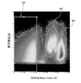
- FIG. 5 is a scattergram with the CD71: FITC fluorescence intensity as the vertical axis and the DRAQ5: APC fluorescence intensity as the horizontal axis for the group of the region W2 selected in FIG.
- the fluorescence intensity of CD71: FITC is associated with erythrocyte juvenile
- the fluorescence intensity of DRAQ5: APC is associated with the nucleus. Therefore, by gating DRAQ5: APC positive, a region W5 where nucleated red blood cells are considered to appear is selected. The population where nucleated red blood cells are expected to appear is separated from other populations.
- a group that is considered to have nucleated red blood cells selected by the region W5 from the result of the above analysis is sorted into the container 20 by the flow cytometer 10.
- FIGS. 6 and 7 are perspective views of the container 20.
- the container 20 has a plurality of wells 202 having openings and a bottom surface, and a plurality of wells 202 and an integrally structured side wall 204 for collecting a plurality of cells.
- the plurality of wells 202 are arranged in rows and columns.
- a numerical value indicating a row and an alphabetic character indicating a column are displayed on the opening side of the well 202 of the container 20.
- cells are collected in each well 202.
- an identification mark 206 such as a barcode is displayed on the side wall of the container 20, for example.
- the container 20 in a form different from that of FIG. 6 includes a plurality of tubes 208 having openings and bottom surfaces for collecting a plurality of cells, and a plurality of tubes for holding the plurality of tubes 208. And a support member 210 having a plurality of holes 212.
- the tube 208 performs the function of a well.
- the shape of the well is not limited as long as it has an opening and a bottom surface for containing cells.
- a plurality of holes 212 are formed in rows and columns.
- a numerical value indicating a row and an alphabetic character indicating a column are displayed on the side of the container 20 where the hole 212 is formed.
- the cells are collected in each tube 208 held by the support member 210.
- an identification mark 206 such as a barcode is displayed on the side wall of the support member 210, for example.
- the tube 208 may be, for example, a single tube or a tube in which a plurality of tubes are connected.
- the tube 208 may be a tube having a cap (not shown).
- the cells in the selected region W5 are sorted into the well 202 of the container 20 or the tube 208 of the container 20 by the flow cytometer 10 basically in units of one cell.
- the control unit 120 preferably stores the position (well 202 or tube 208) of the container 20 in which the cells are stored and the first information derived from the cells in association with each other.
- the position of the container 20 containing the cells is preferably specified by the row and column displayed on the container 20 and the identification mark 206.
- ⁇ Amplification step (step S3)> the DNA of the cells sorted in the container is amplified.
- the amplification step preferably includes a polymerase chain reaction.
- PCR polymerase chain reaction
- the container 20 containing the sorted cells is set in the PCR device.
- the container set in the PCR apparatus may be the container 20 in which the cells used in the flow cytometer 10 are collected, or may be a PCR container in which the cells are moved from the container 20.
- the cell sorted in the container means the cell sorted in the container in the sorting process, and it means that the cell only needs to be amplified in the amplification process, and means that the container in the sorting process is used. is not.
- the first information derived from the cells in the sorting step and the position information of the container 20 from which the cells have been sorted are In association with the container set in the PCR device, for example, it is stored in the control unit 120.
- the reaction solution is heated to about 94 ° C., and the temperature is maintained for 30 seconds to 1 minute to separate the double-stranded DNA into single strands.
- the reaction solution is rapidly cooled to about 60 ° C., the single-stranded DNA and the primer are heated (annealed) to a predetermined temperature, and the single-stranded DNA and the primer are heated.
- the DNA polymerase is reacted with the primer, and heating is performed to a temperature suitable for DNA polymerase activity (about 60 to 72 ° C.) without causing separation of the single-stranded DNA and the primer. This state is continued for the time required for DNA synthesis (usually 1 to 2 minutes depending on the length of amplification).
- a specific DNA fragment can be amplified by executing a plurality of cycles, for example, 20 cycles, with the first to third cycles as one cycle.
- the target portion can be amplified 2n times from one double-stranded DNA.
- amplification procedure described above is an example of the polymerase chain reaction, and is not limited thereto.
- second information related to the amplification result is acquired.
- the second information whether or not the DNA of the target cell has been amplified, that is, the presence or absence of amplification, is preferably acquired as the second information. Based on the presence or absence of amplification, it can be determined whether the sorted cells are live or dead.
- the cell-derived first information and the second information acquired in the amplification step are associated with each other, and are input and stored in the control unit 120, for example.
- the second information regarding the presence or absence of DNA amplification can be preferably obtained by performing electrophoresis on a DNA fragment using an agarose gel.
- the presence or absence of DNA or the presence or absence of DNA amplification can be confirmed from the DNA size by electrophoresis.
- ⁇ Analysis process (step S4)>
- the amplified DNA is genetically analyzed.
- the gene analysis is preferably selected from the group consisting of DNA microarray method, digital PCR method, real-time PCR method, sequencer method and combinations thereof. Although it does not specifically limit as a gene analysis, Furthermore, it is possible to use nCounter System (NanoString company). In the present embodiment, it is preferable to use a so-called next-generation sequencer method in terms of the accuracy and speed of analysis, and the number of samples that can be processed at one time.
- the DNA microarray method is a method of analyzing gene information expressed in cells by arranging DNA fragments of cells at high density on a substrate and hybridizing with DNA sequences on a plate.
- the digital PCR method is a method of distributing a target sample to a plurality of wells, individually executing PCR in parallel, and counting the number of positive reactions at the end of amplification.
- next-generation sequencer means a sequencer classified in comparison with a capillary sequencer (referred to as a first generation sequencer) using the Sanger method.
- Next-generation sequencers include second generation, third generation, and fourth generation.
- the most popular next-generation sequencer at present is a sequencer based on the principle of determining a base sequence by capturing fluorescence or light emission linked to complementary strand synthesis by DNA polymerase or complementary strand binding by DNA ligase. Specific examples include MiSeq (Illumina), HiSeq2000 (Illumina, HiSeq is a registered trademark), Roche 454 (Roche).
- Examples of means for aligning sequence data obtained by the next-generation sequencer include Burrows-Wheeler Aligner (BWA), and it is preferable to map sequence data to a known human genome sequence by BWA.
- Examples of means for analyzing genes include SAMtools and BEDtools, and it is preferable to analyze gene polymorphisms, gene mutations, and chromosome numbers by these analysis means.
- 3rd information related to the result of gene analysis is acquired by performing gene analysis of the amplified DNA.
- the third information whether or not the sorted cell is the target cell, that is, the presence or absence of the target cell is preferably acquired as the third information.
- the cell-derived first information and the third information acquired in the analysis step are input and stored in the control unit 120 in association with each other, for example.
- Step S5 the extraction condition in the sorting step is redetermined based on at least one of the second information acquired in the amplification step and the third information acquired in the analyzing step.
- Re-determination of extraction conditions is to re-determine the extraction conditions determined in the preparative process, and when changing the extraction conditions determined in the preparative process, and to change the extraction conditions determined in the preparative process Including the case of not.
- the extraction conditions include appropriate combinations of selection of the vertical axis or horizontal axis for creating a scattergram, gating for separating another group from the group, gate-out, and the like.
- first information including at least one of fluorescence emission by immunostaining, forward scattered light, and side scattered light is acquired, and the first information is analyzed according to the determined extraction condition, From the results, the cells considered as the target cells are separated. For this reason, it has been difficult to sort out cells that are not targeted (for example, dead cells) and cells that are difficult to separate into a plurality of populations from only normal first information.
- the second information and the third information is acquired in the amplification process and the analysis process in association with the first information.
- the amplification step and the analysis step it can be determined whether the sorted cells are the target cells.
- the second information includes information on the presence or absence of gene amplification, it can be determined whether the sorted cell is a live cell or a dead cell.
- the third information includes genetic information, it can be determined whether the sorted cell is the target cell.
- the second information and the third information Since at least one of the second information and the third information is associated with the first information, it can be fed back to the extraction condition determined in the sorting step based on the second information and the third information. . Accordingly, it is possible to redetermine the extraction conditions that allow the target cells to be sorted with higher probability.
- FIG. 8 is a scattergram after re-determining the extraction conditions based on the second information of the amplification process with respect to the scattergram of FIG.
- the first information associated with the second information acquired in the amplification process is fed back to the control unit 120 of the flow cytometer 10, for example.
- the control unit 120 can redetermine the extraction condition based on the fed-back second information.
- a region W6 is newly selected.
- the region W6 in which the result based on the second information in the region W5 is reflected is presumed to be a region where many cells that have not been amplified (dead cells) appear.
- a new area W7 is selected. In the region W7, it is estimated that many nucleated red blood cells and viable cells appear.
- FIG. 9 is a scattergram after re-determining the extraction conditions based on the third information of the analysis process with respect to the scattergram of FIG.
- the first information associated with the third information acquired in the analysis step is fed back to the control unit 120 of the flow cytometer 10, for example.
- the control unit 120 can redetermine the extraction condition based on the fed back third information.
- a region W8 and a region W9 are newly selected.
- the region W8 reflecting the result based on the third information in the region W7 is a region where many nucleated red blood cells derived from the mother appear
- the region W9 is estimated as a region where many nucleated red blood cells derived from the fetus appear. Is done.
- the extraction condition is redetermined based on the second information and the third information.
- the extraction condition is reset based on at least one information of the second information and the third information. You may decide. By re-determining the extraction condition based on at least one piece of information, the target cell can be sorted with a higher probability, and a highly reliable gene analysis method can be realized.
- FIG. 10 is a flowchart of the gene analysis method of the second embodiment.
- the gene analysis method includes a staining step (step S21), a sorting step (step S22), an imaging step (step S23), an amplification step (step S24), an analysis step (step S25), and A condition determining step (step S26) is provided at least.
- step S21 cells are stained.
- step S22 the first information derived from the cells of the sample solution is obtained by flow cytometry, the first information is analyzed according to the determined extraction conditions, and a plurality of target cells are determined from the analysis results. Aliquot into wells with wells arranged.
- the imaging step step S23
- the cells sorted in the container are imaged.
- the amplification step step S24
- the DNA of the cells sorted in the container is amplified.
- the analysis step step S25
- the amplified DNA is genetically analyzed.
- the condition determination step (step S26) the extraction condition is based on at least one of the second information acquired in the amplification step, the third information acquired in the analysis step, and the fourth information acquired in the imaging step. Redetermined.
- step 21 Regarding the staining process (step 21) and the sorting process (step S22) of the gene analysis method of the second embodiment, the same staining process (step S1) and sorting process (step S2) as in the first embodiment are performed. can do.
- step S23 Next, the imaging process (step S23) will be described.
- Imaging a cell means capturing an image of a cell, and includes capturing a target cell, a non-target cell, and a foreign substance (dust, cell debris) that is not a cell.
- the image capturing device 30 it is preferable to use the image capturing device 30 to capture details taken in the container 20.
- An example of the image capturing device 30 is a fluorescence microscope including the image capturing device.
- FIG. 11 is a schematic configuration diagram of the image pickup device 30.
- the image pickup device 30 can pick up the cells C collected in the container 20.
- the image capturing device 30 is configured to obtain the cell-derived fourth information by capturing the cell C.
- the cell-derived fourth information includes at least one of fluorescence intensity from the cell, cell shape, color, and size.
- the fluorescence intensity means fluorescence emission of a fluorescent dye by immunostaining excited by excitation light.
- the shape of the cell includes the external and internal forms of the cell.
- the color of the cell means the color of the cell itself.
- the size of the cell includes an area when the cell is viewed two-dimensionally, a volume when the cell is viewed three-dimensionally, and the like.
- the cells sorted into the container 20 are imaged from the side opposite to the opening of the well 202 of the container 20 (ie, the back surface).
- the image pickup device 30 is arranged on the opposite side of the container 20 away from the table 304, the first light source 302 for excitation for measuring the fluorescence of the cell C, the table 304 for placing the container 20 thereon, and the like.
- a filter group including a lens 306, an excitation filter 308, a dichroic mirror 310, and a fluorescent filter 312, and a well 202 side of the container 20, and irradiates the container 20 with light for measuring transmitted light.
- a second light source 314 and an imaging device 316 that images the cell C are provided.
- the cells C sorted into the container 20 are arranged on the side opposite to the opening (surface) of the well 202 of the container 20. That is, the imaging device 316 can image the cell C from the back surface of the container 20. Excitation light from the first light source 302 is applied to the well 202 from the back surface of the container 20, and light from the second light source 314 is applied to the well 202 from the surface of the container 20.
- the material of the container 20 should be transparent, not self-fluorescent, and not scattered. Is preferred.
- the image imaging device 30 can preferably acquire an image obtained by imaging the cells C that emit fluorescence and an image obtained by imaging the cells C in the bright field.
- the first light source 302 for example, a high pressure mercury lamp, a high pressure xenon lamp, a light emitting diode, a laser diode, a tungsten lamp, a halogen lamp, a white light emitting diode, or the like can be used. Even when these light sources are used, only the target wavelength can be transmitted by the excitation filter 308.
- the fluorescent dye of cell C that has been immunostained can be irradiated with light having a target excitation wavelength. Note that a light source similar to the first light source 302 can be used as the second light source 314.
- a case will be described in which an image is acquired by the imaging device 316 of fluorescence intensity obtained by immunostaining the cell C.
- the light emitted from the first light source 302 is transmitted only by the excitation filter 308 in the target wavelength region.
- the light transmitted through the excitation filter 308 is reflected by the dichroic mirror 310 toward the container 20.
- the light reflected by the dichroic mirror 310 passes through the lens 306 and irradiates the cells C collected in the well 202.
- the light irradiated to the cell C is in a wavelength region that excites the fluorescent dye of the immunostained cell C.
- the immunostained cell C is excited by excitation light and emits fluorescence having a wavelength different from the irradiated excitation wavelength.
- the fluorescence of the cell C by immunostaining is imaged by the imaging device 316 via the lens 306, the dichroic mirror 310, and the fluorescence filter 312, and an image is acquired.
- the wavelength of the fluorescence is longer than the wavelength of the excitation light. Therefore, the dichroic mirror 310 reflects the light to the wavelength of the excitation light toward the container 20, and the wavelength of the fluorescence. Light can be transmitted to the imaging device 316 side.
- the fluorescent filter 312 can transmit only fluorescence without transmitting excitation light. Therefore, the imaging device 316 can image the cells C that emit fluorescence by immunostaining. Since only the fluorescence is transmitted through the fluorescent filter 312, the image captured by the imaging device 316 is not affected by the excitation light, and thus an accurate image can be acquired.
- the image capturing apparatus 30 of the present embodiment includes a table 304 and a driving device (not shown) for moving the container 20 to an arbitrary position (for example, the X direction, the Y direction, and the Z direction).
- the specific well 202 of the container 20 can be moved to the observation position by the table 304 and the driving device. It is preferable that the driving device can move the table 304 in the X direction, the Y direction, and the Z direction.
- the cell C When the cell C is immunostained with a plurality of fluorescent dyes, by switching to different filter groups (excitation filter 308, dichroic mirror 310, and fluorescent filter 312), the cells C emitting different fluorescent light can be imaged, and an image of the cell C is obtained. Can be obtained.
- different filter groups excitation filter 308, dichroic mirror 310, and fluorescent filter 312
- the imaging device 316 is not particularly limited as long as it can capture the fluorescence or transmitted light of the cells in the well 202 of the container 20, and for example, a CCD (charge-coupled device) camera can be used.
- a CCD charge-coupled device
- the image capturing device 30 in which the image capturing device 316, the first light source 302, and the filter group are disposed on the back surface side of the container 20 and the second light source 314 is disposed on the front surface side of the container has been described.
- the image pickup device 316, the first light source 302, and the filter group are arranged on the front surface side of the container 20 and the second light source 314 is arranged on the rear surface side of the container. it can.
- the fourth information acquired by imaging the cell in the imaging step is input and stored in, for example, the control unit 120 of the flow cytometer 10 in association with the first information derived from the cell. Since the image captured by the cell C is acquired in the imaging process, information including at least one of the fluorescence intensity, shape, color, and size of the cell can be acquired as the fourth information from the image. In the imaging process, the fourth information is acquired by directly observing the cells, so it is possible to determine whether the sorted cells are target cells, non-target cells, dust, or cell debris. It becomes possible.
- step S24 For the amplification step (step S24) and the analysis step (step S25) of the gene analysis method of the second embodiment, the same amplification step (step S3) and analysis step (step S4) as in the first embodiment are performed. Can do. Next, the condition determining step (step S26) will be described.
- the extraction condition in the sorting step is based on at least one of the second information acquired in the amplification step, the third information acquired in the analysis step, and the fourth information acquired in the imaging step. Redetermined.
- the second information includes the presence or absence of gene amplification
- the third information includes genetic information
- the fourth information includes the fluorescence intensity of the cell, it can be determined from the captured image whether the target cell is the target cell.
- the extraction condition in the sorting process is determined based on the second information, the third information, and the fourth information. You can give feedback. Accordingly, it is possible to redetermine the extraction conditions that allow the target cells to be sorted with higher probability.
- FIG. 12 is a scattergram after re-determining the extraction conditions based on the fourth information of the imaging process with respect to the scattergram of FIG.
- related with the 4th information acquired at the imaging process is fed back to the control part 120 of the flow cytometer 10, for example.
- the control unit 120 can redetermine the extraction condition based on the fed back fourth information.
- a region W10 is newly selected.
- the region W10 in which the result based on the fourth information in the region W5 is reflected is presumed to be a region where a large amount of dust or cell debris appears.
- a new region W11 is selected by gate-out of the region W10. It is estimated that many nucleated red blood cells excluding dust or cell debris appear in the region W11.
- the region W11 where many target cells excluding dust or cell debris appear can be separated from other populations with high probability. it can.
- FIG. 13 is a scattergram after re-determining the extraction conditions based on the second information of the amplification process with respect to the scattergram of FIG.
- the first information associated with the second information acquired in the amplification process is fed back to the control unit 120 of the flow cytometer 10, for example.
- the control unit 120 can redetermine the extraction condition based on the fed-back second information.
- a region W6 is newly selected.
- the region W6 in which the result based on the second information in the region W11 is reflected is presumed to be a region where many cells that have not been amplified (dead cells) appear.
- a new area W7 is selected in the area W11. In the region W7, it is estimated that many nucleated red blood cells and viable cells appear.
- the first information associated with the third information acquired in the analysis process is fed back to the control unit 120 of the flow cytometer 10, for example.
- the control unit 120 can redetermine the extraction condition based on the fed back third information.
- the region W8 reflecting the result based on the third information in the region W7 is a region where many nucleated red blood cells derived from the mother appear, and the region W9 is estimated as a region where many nucleated red blood cells derived from the fetus appear. Is done. By re-determining the extraction conditions based on the third information, it becomes possible to separate the region W9 where many target cells (if fetal nucleated red blood cells) appear from other populations with high probability. I understand that.
- the extraction condition is redetermined based on the second information, the third information, and the fourth information.
- at least one piece of information of the second information, the third information, and the fourth information The extraction condition may be re-determined based on the above. By re-determining the extraction condition based on at least one piece of information, the target cell can be sorted with a higher probability, and a highly reliable gene analysis method can be realized.
- the concentration process which raises the density
- concentration step a case where nucleated red blood cells in the maternal blood are concentrated will be described.
- ⁇ Concentration process> It is preferable to concentrate the nucleated red blood cells in the maternal blood before the staining step to increase the density of the nucleated red blood cells.
- concentration step a known method such as density gradient centrifugation, MACS (Magnetic activated cell sorting), FACS (Fluorescence activated cell sorting), lectin, or filter filtration can be used.
- density gradient centrifugation MACS (Magnetic activated cell sorting), FACS (Fluorescence activated cell sorting), lectin, or filter filtration.
- concentration by density gradient centrifugation as a simple concentration method utilizing the characteristics of blood cells.
- a density gradient centrifugation method will be described below.
- the density gradient centrifugation method is a method of separating using the difference in density of components in blood. Density gradient centrifugation is a method that does not use a separation medium, a method that uses one type of separation medium to separate the top and bottom of the separation medium, or uses two types of separation media.
- the target component (nucleated erythrocytes in this embodiment) can be collected using a method of separating the density region of the target component so as to be sandwiched between the separation media. Then, nucleated red blood cells can be concentrated from maternal blood by collecting a fraction containing the target component.
- nucleated red blood cells can be concentrated.
- the separation medium is injected into the bottom of the centrifuge tube, and the mother's peripheral blood, which is a blood sample, may be diluted on the separation medium (may be diluted with a diluent). Centrifugation is carried out after laminating the nucleated cells, and nucleated red blood cells can be concentrated by collecting the upper part of the separation medium after centrifugation (which may include a part of the separation medium).
- the first separation medium is injected into the bottom of the centrifuge tube, the second separation medium is laminated on the first separation medium, and the second separation medium is then separated.
- the maternal peripheral blood (which may be diluted with a diluent), which is a blood sample, is laminated on the medium for centrifuging and then centrifuged, and the first separation medium and the second separation medium after centrifugation are separated.
- the nucleated red blood cells can be concentrated by collecting an intermediate layer (which may include a part of each of the first separation medium and the second separation medium or a part of either one).
- the centrifuge tube in which the first separation medium is stacked is cooled before the second separation medium is stacked, mixing in the boundary region between the first and second separation media can be suppressed.
- the density of maternal blood including fetal nucleated red blood cells is about 1.065 to 1.095 g / mL
- the density of maternal blood cells is about 1.070 to 1.120 g / mL for red blood cells.
- Acidocytes are about 1.090 to 1.110 g / mL
- neutrophils are about 1.075 to 1.100 g / mL
- basophils are about 1.070 to 1.080 g / mL
- lymphocytes are about 1.060.
- About 1.080 g / mL and mononuclear cells are about 1.060-1.070 g / mL.
- the density of the separation medium to be stacked is set to separate fetal nucleated red blood cells having a density of about 1.065 to 1.095 g / mL from other blood cell components in the mother body.
- the density of the center of fetal nucleated red blood cells is about 1.080 g / mL, so two separation media having different densities sandwiching this density are prepared. Then, by layering adjacently, it becomes possible to collect nucleated red blood cells derived from a desired fetus at the interface.
- the density of the first separation medium is set to 1.08 g / mL or more and 1.10 g / mL or less
- the density of the second separation medium is set to 1.06 g / mL or more and 1.08 g / mL or less.
- the density of the first separation medium is 1.08 g / mL or more and 1.09 g / mL or less
- the density of the second separation medium is 1.065 g / mL or more and 1.08 g / mL or less.
- the density of the first separation medium to 1.085 g / mL and the density of the second separation medium to 1.075 g / mL
- plasma components, eosinophils and Nucleocytes can be separated from the desired fraction to be collected. It is also possible to separate some of red blood cells, neutrophils, and lymphocytes.
- the first separation medium and the second separation medium may be the same type or different types, as long as the effects of the present invention can be realized, but the same type of medium may be used. This is a preferred embodiment.
- Separation media for density gradient centrifugation used in the concentration step include Histopaque (registered trademark), which is a solution containing polysucrose and sodium diatrizoate, and a silica sol with a diameter of 15 to 30 nm coated with non-dialyzable polyvinylpyrrolidone.
- Separation media such as Percoll®, a solution, Ficoll®-Paque, a neutral hydrophilic polymer solution rich in side chains made from sucrose, can be used. In this embodiment, it is preferable to use Histopaque and Percoll.
- the separation medium for density gradient centrifugation can be prepared to have a desired density by mixing diluents or separation media having different densities (specific gravity).
- Histopaque® uses a commercially available medium with a density of 1.077 and a medium with a density of 1.119 to adjust the first separation medium and the second separation medium to a desired density. Is possible.
- These density gradient centrifugation media can be adjusted in osmotic pressure by adding sodium chloride (NaCl) or the like.
Abstract
フローサイトメトリー法を利用した信頼性の高い遺伝子解析方法を提供する。遺伝子解析方法は、細胞を染色する染色工程と、フローサイトメトリー法により試料液の細胞由来の第1情報を取得し、決定された抽出条件に従って第1情報を分析し、分析の結果から目的の細胞を、複数のウェルが配列された容器に分取する分取工程と、容器に分取された細胞のDNAを増幅する増幅工程と、増幅されたDNAを遺伝子解析する解析工程と、増幅工程において取得された第2情報、及び解析工程において取得された第3情報の少なくとも一つの情報に基づいて、抽出条件を再決定する条件決定工程と、を備える。
Description
本発明は遺伝子解析方法に関する。
試料液から目的の細胞を、フローサイトメトリー法を利用することにより、分離し分取することが知られている。
例えば、特許文献1には、染色体異常に起因して生じる、細胞の一部が分離した微小な細胞(小核)を、フローサイトメータ(フローサイトメトリー法に用いられる装置)のソーティング機能を用いて、主核(親核)と小核に分離して回収することが記載されている。
フローサイトメトリー法では、細胞から前方散乱光、側方散乱光、及び蛍光強度の情報を取得することにより細胞を選別し、目的の細胞を複数のウェルを有する容器に、1ウェルに1細胞を分取することが行われている。細胞が分取された容器が、PCR(Polymerase Chain Reaction)装置にセットされ、DNA(Deoxyribonucleic Acid)が増幅され、遺伝子解析が行われる。
しかしながら、フローサイトメトリー法では、蛍光強度の情報に基づいて、目的の細胞を選別しているため、染色の非特異性により誤選別される場合がある。また、細胞が分取する際に死細胞を選別できない場合がある。また、フローサイトメトリー法の蛍光強度の情報のみでは選別が難しい場合もある。例えば、フローサイトメトリー法では有核赤血球を選別可能な一方で、有核赤血球を、母体由来の有核赤血球と胎児由来の有核赤血球とに選別することは困難であった。
上述したように、フローサイトメトリー法において目的の細胞を正確に選別できない場合、その後の遺伝子解析の結果に対する信頼性が低下し、誤った判断を下す問題を含んでいる。
本発明は、このような事情に鑑みてなされたもので、フローサイトメトリー法を利用した信頼性の高い遺伝子解析方法を提供することを目的とする。
本発明の一態様によると、遺伝子解析方法は、細胞を染色する染色工程と、フローサイトメトリー法により試料液の細胞由来の第1情報を取得し、決定された抽出条件に従って第1情報を分析し、分析の結果から目的の細胞を、複数のウェルが配列された容器に分取する分取工程と、容器に分取された細胞のDNAを増幅する増幅工程と、増幅されたDNAを遺伝子解析する解析工程と、増幅工程において取得された第2情報、及び解析工程において取得された第3情報の少なくとも一つの情報に基づいて、抽出条件を再決定する条件決定工程と、を備える。
好ましくは、細胞の染色は、抗原抗体反応による免疫染色である。
好ましくは、第1情報は、免疫染色による蛍光発光、前方散乱光、及び側方散乱光のうちの少なくとも1つの情報である。
好ましくは、分取工程と増幅工程との間に、容器に分取された細胞を撮像する撮像工程とを備え、撮像工程において取得された第4情報に基づいて、抽出条件を再決定する。
好ましくは、第4情報は細胞の蛍光強度、形状、色、及び大きさの少なくとも一つを含む。
好ましくは、第2情報はDNAの増幅の有無を含み、第3情報は目的の細胞の有無を含む。
好ましくは、増幅工程が、ポリメラーゼ連鎖反応を含む。
好ましくは、遺伝子解析が、DNAマイクロアレイ法、デジタルPCR法、リアルタイムPCR法、シークエンサー法及びその組合せよりなる群から選択される。
好ましくは、染色工程の前に、溶媒中の細胞の濃度を高める濃縮工程を備える。
本発明の別の態様によると、遺伝子解析方法は、細胞を染色する工程と、フローサイトメトリー法により試料液の細胞由来の第1情報を取得し、決定された抽出条件に従って第1情報を分析し、分析の結果から目的の細胞を、複数のウェルが配列された容器に分取する分取工程と、容器に分取された細胞を撮像する撮像工程と、容器に分取された細胞のDNAを増幅する増幅工程と、増幅されたDNAを遺伝子解析する解析工程と、増幅工程において取得された第2情報、解析工程において取得された第3情報、及び撮像工程において取得された第4情報の少なくとも一つの情報に基づいて、抽出条件を再決定する条件決定工程と、を備える。
本発明の遺伝子解析方法によれば、フローサイトメトリー法を利用した信頼性の高い遺伝子解析を実現することができる。
以下、添付図面にしたがって本発明の好ましい実施形態について説明する。本発明は以下の好ましい実施形態により説明される。本発明の範囲を逸脱すること無く、多くの手法により変更を行うことができ、実施形態以外の他の実施形態を利用することができる。したがって、本発明の範囲内における全ての変更が特許請求の範囲に含まれる。
ここで、図中、同一の記号により示される部分は、同様の機能を有する同様の要素である。また、本明細書中で、数値範囲を“ ~ ”を用いて表す場合は、“ ~ ”により示される上限、下限の数値も数値範囲に含むものとする。
<遺伝子解析方法>
(第1実施形態)
第1実施形態の遺伝子解析方法について、図面を参照して説明する。なお、本実施形態では、試料液に血球細胞が含まれる場合であって、目的の細胞が胎児由来の有核赤血球である場合を例示して説明する。
(第1実施形態)
第1実施形態の遺伝子解析方法について、図面を参照して説明する。なお、本実施形態では、試料液に血球細胞が含まれる場合であって、目的の細胞が胎児由来の有核赤血球である場合を例示して説明する。
図1は、第1実施形態の遺伝子解析方法のフローチャートである。図1に示されるように、遺伝子解析方法は、染色工程(ステップS1)、分取工程(ステップS2)、増幅工程(ステップS3)、解析工程(ステップS4)、及び条件決定工程(ステップS5)を、少なくとも備える。
染色工程(ステップS1)では、細胞を染色する。分取工程(ステップS2)では、フローサイトメトリー法により試料液の細胞由来の第1情報を取得し、決定された抽出条件に従って第1情報を分析し、分析の結果から目的の細胞を、複数のウェルが配列された容器に分取する。増幅工程(ステップS3)では、容器に分取された細胞のDNAを増幅する。解析工程(ステップS4)では、増幅されたDNAを遺伝子解析する。条件決定工程(ステップS5)では、増幅工程において取得された第2情報、及び解析工程において取得された第3情報の少なくとも一つの情報に基づいて、抽出条件を再決定する。以下、各工程について説明する。
<染色工程(ステップS1)>
本実施形態では、細胞を染色する工程を有している。細胞を染色することにより、後述するフローサイトメトリー法において、試料液の細胞由来の第1情報を取得することが可能になる。
本実施形態では、細胞を染色する工程を有している。細胞を染色することにより、後述するフローサイトメトリー法において、試料液の細胞由来の第1情報を取得することが可能になる。
細胞の染色は、抗原抗体反応による免疫染色であることが好ましい。抗原抗体反応とは、抗体が相補的な構造を持つ抗原と特異的に結合することをいい、免疫染色とは、細胞に存在する抗原に、蛍光色素を連結した抗体を結合させることを意味する。
免疫染色には、直接法と間接法とがあり、直接法は、蛍光色素を直接抗体に連結し、抗原と反応させる方法である。一方、間接法は、検出すべき抗原に特異的に結合できる抗体(1次抗体)には蛍光色素を連結せず、その1次抗体に特異的に結合できる抗体(2次抗体)に蛍光色素を連結して検出する方法である。
細胞を抗原抗体反応により免疫染色するものとして、例えば、抗ヒトCD抗体として、抗CD3抗体、抗CD4抗体、抗CD14抗体、抗CD25抗体、抗CD45抗体、抗CD71抗体、及び抗CD127抗体等を例示することができ、蛍光色素として、4’,6-ジアミジン-2’-フェニルインドールジハイドロクロライド(DAPI:4',6-diamidino-2-phenylindole)、ヨウ化プロピジウム(PI:Propidium Iodide)、ピロニンY(Pyronin Y)、フルオレセインイソチオシアネート(FITC:fluorescein isothiocyanate)、フィコエリスリン(PE:phycoerythrin)、アロフィコシアニン(APC:allophicocyanin)、テキサスレッド(TR(登録商標))、Hoechst33342、7-アミノ-アクチノマイシンD(7-AAD)、2‘-デオキシシチジン5’-三リン酸(Cy3)、スルホインドシアニンスクシンイミジルエステル(Cy5)、DRAQ5(登録商標)、Brilliant Violet 570、及びBrilliant Violet 421等を挙げることができる。
試料液は、次のように調製される。まず、目的の細胞を含む分析対象試料を準備する。分析対象試料に、例えば、免疫染色に用いる蛍光色素された抗体を混合し、インキュベーションすることにより、細胞が免疫染色される。抗原抗体反応による免疫染色された細胞を含む試料液が調製される。
<分取工程(ステップS2)>
分取工程では、フローサイトメトリー法を実現するフローサイトメータ10が用いられ、試料液の細胞由来の第1情報が取得され、決定された抽出条件に従って第1情報が分析され、分析の結果から目的の細胞が、複数のウェルが配列された容器に分取される。
分取工程では、フローサイトメトリー法を実現するフローサイトメータ10が用いられ、試料液の細胞由来の第1情報が取得され、決定された抽出条件に従って第1情報が分析され、分析の結果から目的の細胞が、複数のウェルが配列された容器に分取される。
抽出条件は、例えば、スキャッタグラムの分布を見て、過去の知見に基づいて決定される。
図2は、フローサイトメータ10の概念図である。試料液Sには、抗原抗体反応による免疫染色された細胞Cを含む血球細胞が含まれている。
試料液Sがノズル102からフローセル104に導入される。シース液Lがフローセル104に導入される。フローセル104内においてシース液Lにより試料液Sが絞られる。試料液Sが絞られることにより、細胞Cが一列に配列される。
細胞Cに光源106から、例えばレーザ光が照射される。レーザ光の照射により細胞Cの免疫染色が励起され、細胞Cは免疫染色による蛍光を発光する。この蛍光発光の蛍光強度が検知器108により検知される。検知器108により検知された、細胞Cの蛍光発光が、細胞由来の第1情報として取得され、制御部120に入力、及び記憶される。制御部120は、各種の処理を行う演算部、各種プログラム、及びデータ等が格納された記憶部等を備える。
光源106からレーザ光が照射され、免疫染色による細胞Cからの前方散乱光、側方散乱光が検知器110により検知される。検知器110により検知された細胞Cからの前方散乱光、側方散乱光よる蛍光強度が、細胞由来の第1情報として取得され、制御部120に入力、及び記憶される。
第1情報として、免疫染色による蛍光発光、前方散乱光、及び側方散乱光の情報を取得する場合を例示したが、第1情報として、免疫染色による蛍光発光、前方散乱光、及び側方散乱光の少なくとも一つの情報を取得すれば良い。
なお、第1情報として取得された前方散乱光により測定対象の細胞の大きさが、また側方散乱光、及び蛍光発光により、測定対象物の細胞の構造などが測定される。
フローセル104には超音波が印加され、細胞Cを含む液滴が形成される。制御部120は、上記の検出結果に基づいて、液滴をプラス、又はマイナスに荷電する。制御部120は、廃棄する液滴については荷電しない。偏向電極板112、114を通過する際、荷電された液滴を何れかの偏向電極板112、114に引き寄せることにより、基本的には、容器20の1個のウェルに1個の細胞が分取される。
免疫染色を励起させる光源106として、波長の異なる複数のレーザ光源を使用することが好ましい。例えば、405nmの波長を持つレーザ光源と、488nmの波長を持つレーザ光源と、561nmの波長を持つレーザ光源と、683nmの波長を持つレーザ光源と、を備えることが好ましい。波長の異なる複数のレーザ光源を使用することにより、細胞由来の第1情報として、複数の蛍光強度を得ることができる。
また、同時に蛍光強度を検出するためレーザ光源の励起光をカットし、免疫染色による蛍光色素の発光の波長を選択的に透過させる蛍光フィルタを使用することが好ましい。
フローサイトメータ10の制御部120には、細胞由来の第1情報(免疫染色による蛍光発光、前方散乱光、及び側方散乱光)に基づいて、検出結果を解析するための解析プログラムが記憶されている。制御部120は、細胞由来の第1情報を取得し、決定された抽出条件に従って第1情報を分析する。
例えば、制御部120は、例えば、細胞由来の第1情報に基づいて、蛍光発光、前方散乱光、及び側方散乱光の何れかを縦軸又は横軸とする、スキャッタグラム(散布図)を作成することができる。細胞由来の第1情報からスキャッタグラムを作成することにより、目的の細胞を分取するため、検知された全数の細胞を複数の集団に分離することができる。また、第1情報から作成されたスキャッタグラム上において、領域を指定する(いわゆるゲーティング)、又は領域を指定外とする(いわゆる、ゲートアウト)することにより、グラフ上の全数、又は集団から別の集団を分離することができ、目的の細胞が含まれる集団に絞り込みを実施することができる。
本実施形態においては、第1情報の分析は、細胞由来の第1情報から目的の細胞が含まれる集団に絞り込むまでの一連の処理を含み、抽出条件はスキャッタグラムを作成するための縦軸又は横軸の選択や、集団から別の集団を分離するためのゲーティング、ゲートアウトなどを適宜組み合わせて決定することが可能である。
図3から図5は、決定された抽出条件に従って第1情報を分析する場合の一例を示している。図3は有核赤血球を含む領域を選択したスキャッタグラムである。図4は赤血球が出現する領域を選択したスキャッタグラムである。図5は有核赤血球が出現する領域を選択したスキャッタグラムである。
図3は、側方散乱光の蛍光強度を縦軸、前方散乱光の蛍光強度を横軸とするスキャッタグラムである。図3のスキャッタグラムには、フローセルを通過し、第1情報が取得された全数の細胞が表示されている。図3においては、ゲーティングにより有核赤血球を含むと考えられる領域W1が選択され、一方、血小板は領域W1から除外されている。このゲーティングにより、全数の細胞から、有核赤血球を含む領域W1の集団が分離される。
次に、図4は、図3において選択された領域W1の集団を対象とした、前方散乱光の蛍光強度を縦軸、CD45:Brilliant Violet 421の蛍光強度を横軸とするスキャッタグラムである。CD45は白血球共通抗原であり、白血球はBrilliant Violet 421により免疫染色されている。したがって、CD45陰性をゲーティングすることにより、赤血球が出現すると考えられる領域W2が選択される。赤血球が出現すると考えられる集団が、他の集団から分離される。なお、領域W3は顆粒球が出現すると考えられる集団であり、領域W4はリンパ球と単球とが出現すると考えられる集団である。
次に、図5は、図4において選択された領域W2の集団を対象とした、CD71:FITCの蛍光強度を縦軸、DRAQ5:APCの蛍光強度を横軸とするスキャッタグラムである。CD71:FITCの蛍光強度は赤血球の幼弱性に関連し、DRAQ5:APCの蛍光強度は核に関連する。したがって、DRAQ5:APC陽性をゲーティングすることにより、有核赤血球が出現すると考えられる領域W5が選択される。有核赤血球が出現すると考えられる集団が、他の集団から分離される。
本実施形態では、上述の分析の結果から領域W5により選択された有核赤血球が出現すると考えられる集団がフローサイトメータ10により容器20に分取される。
次に、細胞が分取される容器20について説明する。図6、及び図7は容器20の斜視図である。
図6に示されるように、容器20は、複数の細胞を回収するため、開口と底面とを有する複数のウェル202と、複数のウェル202と一体構造の側壁204と、を有している。複数のウェル202は行と列とに配置される。各々のウェル202の位置を特定するために、行を示す数値、及び列を示す英字が容器20のウェル202の開口側に表示されている。図6に示される容器20では、各々のウェル202に細胞が回収される。容器20を特定するため、容器20の側壁には、例えば、バーコード等の識別標識206が表示される。
図7に示されるように、図6とは別の形態の容器20は、複数の細胞を回収するための開口と底面とを有する複数のチューブ208と、複数のチューブ208を保持するための複数の孔212を備える支持部材210と、を有している。図7に示されるように容器20では、チューブ208がウェルの機能を果たしている。細胞を収納するための開口と底面とを有していれば、ウェルの形状等は限定されない。
複数の孔212は行と列とに形成される。各々の孔212の位置を特定するために、行を示す数値、及び列を示す英字が、容器20の孔212の形成される側に表示されている。図7に示される容器20では、支持部材210に保持された各々のチューブ208に細胞が回収される。さらに、容器20を特定するため、支持部材210の側壁には、例えば、バーコード等の識別標識206が表示される。なお、チューブ208は、例えば、1個単位のチューブであっても良いし、複数個が連結されたチューブであっても良い。また、チューブ208はキャップ(不図示)を有するチューブであっても良い。
上述したように、フローサイトメータ10により、選択された領域W5の細胞が、目的の細胞として、容器20のウェル202、又は容器20のチューブ208に基本的には細胞1個単位で分取される。
制御部120は、好ましくは、細胞が収容された容器20の位置(ウェル202又はチューブ208)と、その細胞由来の第1情報とを、関連付けて記憶する。細胞が収容された容器20の位置は、容器20に表示された行と列、及び識別標識206とにより、好ましくは、特定される。
<増幅工程(ステップS3)>
増幅工程では容器に分取された細胞のDNAが増幅される。増幅工程はポリメラーゼ連鎖反応を含むことが好ましい。以下、ポリメラーゼ連鎖反応(PCR:Polymerase Chain Reaction)を例に増幅工程を説明する。
増幅工程では容器に分取された細胞のDNAが増幅される。増幅工程はポリメラーゼ連鎖反応を含むことが好ましい。以下、ポリメラーゼ連鎖反応(PCR:Polymerase Chain Reaction)を例に増幅工程を説明する。
分取された細胞を含む容器20が、PCR装置にセットされる。PCR装置にセットされる容器は、フローサイトメータ10で使用された細胞が分取された容器20であっても良いし、又は容器20から細胞を移動させたPCR用の容器であっても良い。容器に分取された細胞とは、分取工程において容器に分取された細胞を意味し、増幅工程においてその細胞が増幅されれば良く、分取工程の容器を使用することを意味するものではない。但し、PCR装置にセットされる容器が、フローサイトメータ10で使用された容器20と異なる場合、分取工程での細胞由来の第1情報と細胞が分取された容器20の位置情報とは、PCR装置にセットされる容器に関連付けて、例えば、制御部120に記憶される。
PCR装置において、第1に、反応液を94℃程度に加熱し、30秒から1分間温度を保ち、2本鎖DNAを1本鎖に分離する。第2に、反応液を60℃程度にまで急速冷却し、その一本鎖DNAとプライマーを所定の温度に加熱(アニーリング)し、一本鎖DNAとプライマーとを加熱する。第3に、プライマーにDNAポリメラーゼを反応させ、一本鎖DNAとプライマーの分離が起きず、DNAポリメラーゼ活性に適した温度(60~72℃程度)まで、加熱する。DNAが合成されるのに必要な時間(増幅する長さによるが通常1~2分)、この状態を継続する。
第1から第3までを1サイクルとして、複数サイクル、例えば20サイクルを実行することにより特定のDNA断片を増幅することができる。一般的に、PCR処理をn回のサイクル行うと、1つの2本鎖DNAから目的部分を2n倍に増幅することができる。
なお、上述の増幅手順はポリメラーゼ連鎖反応の一例を示したのであって、これ限定されることはない。
増幅工程において、増幅の結果に関連する第2情報が取得される。例えば、第2情報として、目的の細胞のDNAが増幅されたか否か、つまり増幅の有無が第2情報として、好ましくは、取得される。増幅の有無に基づいて、分取された細胞が生細胞か死細胞かを判断することができる。細胞由来の第1情報と増幅工程において取得された第2情報とは関連付けられ、例えば、制御部120に入力、及び記憶される。
DNA増幅の有無に関する第2情報は、好ましくは、DNA断片に対してアガロースゲルを用いた電気泳動を行うことにより取得することができる。電気泳動によりDNAの有無、又はDNAサイズからDNA増幅の有無を確認することができる。
<解析工程(ステップS4)>
解析工程では、増幅されたDNAを遺伝子解析する。遺伝子解析は、DNAマイクロアレイ法、デジタルPCR法、リアルタイムPCR法、シークエンサー法及びその組合せよりなる群から好ましくは、選択される。遺伝子解析として、特に限定されないが、さらに、nCounter System(NanoString社)を用いることが可能である。本実施形態においては、解析の精度、及び速さ、1度に処理可能な試料数の多さ等の点でいわゆる次世代シークエンサー法を用いることが好ましい。
解析工程では、増幅されたDNAを遺伝子解析する。遺伝子解析は、DNAマイクロアレイ法、デジタルPCR法、リアルタイムPCR法、シークエンサー法及びその組合せよりなる群から好ましくは、選択される。遺伝子解析として、特に限定されないが、さらに、nCounter System(NanoString社)を用いることが可能である。本実施形態においては、解析の精度、及び速さ、1度に処理可能な試料数の多さ等の点でいわゆる次世代シークエンサー法を用いることが好ましい。
DNAマイクロアレイ法は、基板上に細胞のDNA断片を高密度に配置し、板上のDNA配列に対して、ハイブリダイゼーションすることによって、細胞内において発現している遺伝子情報を分析する方法である。
デジタルPCR法は、対象のサンプルを複数のウェルに分配し、個別にPCRを並行して実行し、増幅の終了時に陽性反応の数をカウントする方法である。
本実施形態において次世代シークエンサーは、サンガー法を利用したキャピラリーシークエンサー(第一世代シークエンサーと呼ばれる)に対比して分類されるシークエンサーを意味する。次世代シークエンサーは、第二世代、第三世代、第四世代を含む。現時点で最も普及している次世代シークエンサーは、DNAポリメラーゼによる相補鎖合成又はDNAリガーゼによる相補鎖結合に連動した蛍光又は発光をとらえ塩基配列を決定する原理のシークエンサーである。具体的には、MiSeq(Illumina社)、HiSeq2000(Illumina社、HiSeqは登録商標)、Roche454(Roche社)などが挙げられる。
増幅工程で得られたDNAの増幅産物を次世代シークエンサーにより解析する場合、全ゲノムシークエンス、エキソームシークエンス、アンプリコンシークエンスを用いることが可能である。
次世代シークエンサーにより得られた配列データをアライメントする手段としては、Burrows-Wheeler Aligner(BWA)が挙げられ、BWAによって既知のヒトゲノム配列へ配列データをマッピングすることが好ましい。遺伝子を解析する手段としては、SAMtools及びBEDtoolsが挙げられ、これらの解析手段により遺伝子多型、遺伝子変異、及び染色体数を解析することが好ましい。
増幅されたDNAを遺伝子解析することにより、遺伝子解析の結果に関連する第3情報が取得される。例えば、第3情報として、分取された細胞が目的の細胞であるか否か、つまり目的の細胞の有無が第3情報として、好ましくは、取得される。細胞由来の第1情報と、解析工程において取得された第3情報とは、例えば、関連付けて制御部120に入力、及び記憶される。
<条件決定工程(ステップS5)>
条件決定工程では、増幅工程において取得された第2情報、及び解析工程において取得された第3情報の少なくとも一つの情報に基づいて、分取工程における抽出条件を再決定する。
条件決定工程では、増幅工程において取得された第2情報、及び解析工程において取得された第3情報の少なくとも一つの情報に基づいて、分取工程における抽出条件を再決定する。
抽出条件の再決定は、分取工程において決定された抽出条件を改めて決定することであり、分取工程において決定された抽出条件を変更する場合、及び分取工程において決定された抽出条件を変更しない場合を含む。抽出条件には、スキャッタグラムを作成するための縦軸又は横軸の選択や、集団から別の集団を分離するためのゲーティング、ゲートアウトなどを適宜組み合わせることが含まれる。
分取工程では、例えば、免疫染色による蛍光発光、前方散乱光、及び側方散乱光を少なくとも一つを含む第1情報を取得し、決定された抽出条件に従って第1情報を分析し、分析の結果から目的の細胞と考えられる細胞を分取している。そのため、通常の第1情報のみからでは、目的とされない細胞(例えば、死細胞)を分離した分取、及び複数の集団に分離することが難しい細胞等の分取は困難であった。
本実施形態では、分取工程の後、第1情報と関連付けて、増幅工程、及び解析工程において第2情報、及び第3情報を少なくとも一つを取得する。増幅工程、及び解析工程を経ることにより、分取された細胞が、目的の細胞であるか否かを判断できる。好ましくは、第2情報は遺伝子の増幅の有無の情報を含んでいるので、分取された細胞が生細胞、又は死細胞であるかを判断できる。また、第3情報は遺伝子情報を含んでいるので、分取された細胞が目的の細胞であるかを判断できる。
第2情報、及び第3情報の少なくとも一つが、第1情報と関連付けられているので、第2情報、及び第3情報に基づいて、分取工程において決定された抽出条件にフィードバックすることができる。したがって、より高い確率で目的の細胞を分取することが可能な抽出条件を再決定することができる。
図8は、図5のスキャッタグラムに対し、増幅工程の第2情報に基づいて抽出条件を再決定した後のスキャッタグラムである。増幅工程において取得された第2情報に関連付けされた第1情報が、例えば、フローサイトメータ10の制御部120にフィードバックされる。制御部120は、フィードバックされた第2情報に基づいて、抽出条件を再決定することができる。
再決定された抽出条件に基づいて第1情報を分析した結果、新たに領域W6が選択される。領域W5の中の第2情報に基づく結果が反映された領域W6は、増幅しなかった細胞(死細胞)が多く出現する領域であると推定される。領域W6をゲートアウトすることにより、新たな領域W7が選択される。領域W7には有核赤血球であって生細胞が多く出現すると推定される。
第2情報に基づいて抽出条件を再決定することにより、有核赤血球であって生細胞が多く出現する領域W7を、他の集団から高い確率で分離することが可能になることが理解できる。
図9は、図8のスキャッタグラムに対し、解析工程の第3情報に基づいて抽出条件を再決定した後のスキャッタグラムである。解析工程において取得された第3情報に関連付けされる第1情報が、例えば、フローサイトメータ10の制御部120にフィードバックされる。制御部120は、フィードバックされた第3情報に基づいて、抽出条件を再決定することができる。
再決定された抽出条件に基づいて第1情報を分析した結果、新たに領域W8、領域W9が選択される。領域W7の中の第3情報に基づく結果が反映された領域W8は母体由来の有核赤血球が多く出現する領域であり、領域W9は胎児由来の有核赤血球が多く出現する領域であると推定される。第3情報に基づいて抽出条件を再決定することにより、目的の細胞(胎児由来の有核赤血球である場合)が多く出現する領域W9を他の集団から高い確率で分離することが可能となることが理解できる。
本実施形態では、第2情報、及び第3情報に基づいて、抽出条件を再決定する場合について説明したが、第2情報、及び第3情報の少なくとも一つの情報に基づいて、抽出条件を再決定する場合でも良い。少なくとも一つの情報に基づいて、抽出条件を再決定することにより、目的の細胞をより高い確率で分取できるので、信頼性の高い遺伝子解析方法を実現することができる。
(第2実施形態)
次に、第2実施形態の遺伝子解析方法について、図面を参照して説明する。なお、本実施形態では、試料液に血球細胞が含まれる場合であって、目的の細胞が胎児由来の有核赤血球である場合を例示して説明する。
次に、第2実施形態の遺伝子解析方法について、図面を参照して説明する。なお、本実施形態では、試料液に血球細胞が含まれる場合であって、目的の細胞が胎児由来の有核赤血球である場合を例示して説明する。
図10は、第2実施形態の遺伝子解析方法のフローチャートである。図10に示されるように、遺伝子解析方法は、染色工程(ステップS21)、分取工程(ステップS22)、撮像工程(ステップS23)、増幅工程(ステップS24)、解析工程(ステップS25)、及び条件決定工程(ステップS26)を、少なくとも備える。
染色工程(ステップS21)では、細胞を染色する。分取工程(ステップS22)では、フローサイトメトリー法により試料液の細胞由来の第1情報を取得し、決定された抽出条件に従って第1情報を分析し、分析の結果から目的の細胞を、複数のウェルが配列された容器に分取する。撮像工程(ステップS23)では、容器に分取された細胞を撮像する。増幅工程(ステップS24)では、容器に分取された細胞のDNAを増幅する。解析工程(ステップS25)では、増幅されたDNAを遺伝子解析する。条件決定工程(ステップS26)では、増幅工程において取得された第2情報、解析工程において取得された第3情報、及び撮像工程において取得された第4情報の少なくとも一つの情報に基づいて、抽出条件を再決定する。
以下、各工程について説明する。なお、第1実施形態と同様の工程については、その説明を省略する場合がある。
第2実施形態の遺伝子解析方法の染色工程(ステップ21)、及び分取工程(ステップS22)について、第1実施形態と同様の染色工程(ステップS1)、及び分取工程(ステップS2)を実施することができる。次に撮像工程(ステップS23)について説明する。
<撮像工程(ステップS23)>
撮像工程では、容器に分取された細胞を撮像する。細胞を撮像するとは、細胞を対象として撮像する意味であって、目的の細胞、目的外の細胞、細胞ではない異物(ゴミ、細胞破片)を撮像する場合を含んでいる。撮像工程では、容器20に分取された細部を撮像するため画像撮像装置30を用いることが好ましい。画像撮像装置30として、撮像装置を備える蛍光顕微鏡を挙げることができる。
撮像工程では、容器に分取された細胞を撮像する。細胞を撮像するとは、細胞を対象として撮像する意味であって、目的の細胞、目的外の細胞、細胞ではない異物(ゴミ、細胞破片)を撮像する場合を含んでいる。撮像工程では、容器20に分取された細部を撮像するため画像撮像装置30を用いることが好ましい。画像撮像装置30として、撮像装置を備える蛍光顕微鏡を挙げることができる。
図11は画像撮像装置30の概略構成図である。画像撮像装置30は、容器20に回収された細胞Cを撮像することができる。画像撮像装置30は、細胞Cを撮像することにより、細胞由来の第4情報を得ることができるように構成されている。ここで、細胞由来の第4情報には、細胞からの蛍光強度、細胞の形状、色、及び大きさの少なくとも一つが含まれている。蛍光強度とは、励起光により励起された免疫染色による蛍光色素の蛍光発光を意味する。細胞の形状とは、細胞の外部、及び内部の形態を含む。細胞の色とは、細胞自身の色を意味する。細胞の大きさとは、細胞を二次元的に見た面積、細胞を三次元的に見た体積等を含む。
本実施形態では、撮像工程において、容器20に分取された細胞を、容器20のウェル202の開口と反対の側(すなわち裏面)から細胞を撮像する場合について説明する。
画像撮像装置30は、細胞Cの蛍光を測定するための励起用の第1光源302と、容器20を載置するためのテーブル304と、テーブル304から離間して容器20の反対側に配置されたレンズ306と、励起フィルタ308、ダイクロイックミラー310及び蛍光フィルタ312とから構成されるフィルタ群と、容器20のウェル202の側に配置され、透過光を測定するための光を容器20に照射する第2光源314と、細胞Cを撮像する撮像装置316と、を備えている。
なお、撮像装置316は、容器20に分取された細胞Cを容器20のウェル202の開口(表面)と反対の側に配置されている。すなわち、撮像装置316は、容器20の裏面から細胞Cを撮像することができる。第1光源302からの励起光は、容器20の裏面からウェル202に照射され、第2光源314からの光は、容器20の表面からウェル202に照射される。
容器20の裏面側から励起光を照射、又は容器20を透過して細胞からの蛍光、及び、透過光を受光するため、容器20の材料が透明であること、自家蛍光しないこと、散乱しないことが好ましい。
画像撮像装置30は、好ましくは、蛍光発光する細胞Cを撮像した画像、及び明視野による細胞Cを撮像した画像を取得することができる。
第1光源302として、例えば、高圧水銀ランプ、高圧キセノンランプ、発光ダイオード、レーザダイオード、タングステンランプ、ハロゲンランプ、白色発光ダイオードなどを用いることができる。これらの光源を用いても励起フィルタ308により、目的の波長のみ透過させることができる。免疫染色された細胞Cの蛍光色素に対して、目的の励起波長の光を照射させることができる。なお、第2光源314として、第1光源302と同様の光源を用いることができる。
細胞Cの免疫染色による蛍光強度を撮像装置316により画像を取得する場合について説明する。第1光源302から照射された光は、励起フィルタ308により、目的とされる波長領域の光のみ透過される。励起フィルタ308を透過した光は、ダイクロイックミラー310により、容器20の方向に反射される。ダイクロイックミラー310により反射された光は、レンズ306を透過し、ウェル202に回収された細胞Cに照射される。細胞Cに照射される光は、免疫染色された細胞Cの蛍光色素を励起する波長領域とされている。免疫染色された細胞Cは励起光により励起され、照射された励起波長とは異なる波長の蛍光を発光する。細胞Cの免疫染色による蛍光は、レンズ306、ダイクロイックミラー310、及び蛍光フィルタ312を経て撮像装置316で撮像され、画像が取得される。励起光とその励起光により発する蛍光と比較すると、蛍光の波長が励起光の波長より長くなるので、ダイクロイックミラー310により、励起光の波長に光を容器20の側に反射させ、蛍光の波長の光を撮像装置316の側に透過させることができる。また、蛍光フィルタ312は、励起光を透過させず、蛍光のみを透過させることができる。したがって、撮像装置316において、免疫染色による蛍光発光する細胞Cを撮像することができる。蛍光フィルタ312により、蛍光のみを透過させることにより、撮像装置316で撮像される画像が励起光に影響されることがないので、正確な画像を取得することができる。
本実施形態の画像撮像装置30は、容器20を任意の位置に移動(例えば、X方向、Y方向、及びZ方向)させるため、テーブル304と駆動装置(不図示)とを備えている。テーブル304と駆動装置とにより、容器20の特定のウェル202を、観察位置に移動させることができる。駆動装置は、テーブル304を、X方向、Y方向、及びZ方向に移動できることが好ましい。
細胞Cが複数の蛍光色素により免疫染色されている場合、異なるフィルタ群(励起フィルタ308、ダイクロイックミラー310及び蛍光フィルタ312)に切り替えることで、異なる蛍光発光する細胞Cを撮像でき、細胞Cの画像を取得することができる。
撮像装置316としては、容器20のウェル202内の細胞の蛍光または透過光を撮像することができれば特に限定されず、例えば、CCD(charge-coupled device)カメラを用いることができる。
本実施形態では、撮像装置316と第1光源302とフィルタ群とが容器20の裏面側に配置され、第2光源314が容器の表面側に配置されている画像撮像装置30について説明した。これに限定されず、撮像装置316と第1光源302とフィルタ群とが容器20の表面側に配置され、第2光源314が容器の裏面側に配置される画像撮像装置30を使用することもできる。
撮像工程において細胞を撮像することにより取得された第4情報は、細胞由来の第1情報と関連付けて、例えばフローサイトメータ10の制御部120に入力、及び記憶される。撮像工程では細胞Cが撮像した画像が取得されているので、画像から第4情報として、細胞の蛍光強度、形状、色、及び大きさの少なくとも一つを含む情報を取得することができる。撮像工程では直接細胞を観察して第4情報を取得しているので、分取された細胞が、目的の細胞、目的外の細胞、ゴミ、又は細胞破片であるか否かを判断することが可能になる。
本実施形態では、図6に示される容器20を使用した場合を説明したが、これに限定されず、図7に示される容器20を使用して細胞を撮像することができる。
第2実施形態の遺伝子解析方法の増幅工程(ステップS24)、及び解析工程(ステップS25)について、第1実施形態と同様の増幅工程(ステップS3)、及び解析工程(ステップS4)を実施することができる。次に条件決定工程(ステップS26)について説明する。
<条件決定工程(ステップS26)>
条件決定工程では、増幅工程において取得された第2情報、解析工程において取得された第3情報、及び撮像工程において取得された第4情報の少なくとも一つの情報に基づいて、分取工程における抽出条件を再決定する。
条件決定工程では、増幅工程において取得された第2情報、解析工程において取得された第3情報、及び撮像工程において取得された第4情報の少なくとも一つの情報に基づいて、分取工程における抽出条件を再決定する。
本実施形態では、分取工程の後、第1情報と関連付けて、増幅工程、解析工程、及び撮像工程において、第2情報、第3情報、及び第4情報を少なくとも一つを取得する。増幅工程、解析工程、及び撮像工程を経ることにより、分取された細胞が、目的の細胞であるか否かを判断できる。好ましくは、第2情報は遺伝子の増幅の有無を含んでいるので、分取された細胞が生細胞、死細胞であるかを判断できる。また、第3情報は遺伝子情報を含んでいるので、分取された細胞が目的の細胞であるかを判断できる。また、第4情報は細胞の蛍光強度等を含んでいるので、撮像した画像から目的の細胞であるかを判断できる。
第2情報、第3情報、及び第4情報の少なくとも一つが、第1情報と関連付けられているので、第2情報、第3情報、及び第4情報に基づいて、分取工程における抽出条件にフィードバックすることができる。したがって、より高い確率で目的の細胞を分取することが可能な抽出条件を再決定することができる。
図12は、図5のスキャッタグラムに対し、撮像工程の第4情報に基づいて抽出条件を再決定した後のスキャッタグラムである。撮像工程で取得された第4情報に関連付けされた第1情報が、例えば、フローサイトメータ10の制御部120にフィードバックされる。制御部120は、フィードバックされた第4情報に基づいて、抽出条件を再決定することができる。
再決定された抽出条件に基づいて第1情報を分析した結果、新たに領域W10が選択される。領域W5の中の第4情報に基づく結果が反映された領域W10は、ゴミ又は細胞破片が多く出現する領域であると推定される。領域W10をゲートアウトすることにより、新たな領域W11が選択される。領域W11にはゴミ又は細胞破片を除く有核赤血球が多く出現すると推定される。
第4情報に基づいて抽出条件を再決定することにより、ゴミ又は細胞破片等を除く目的の細胞が多く出現する領域W11を、他の集団から高い確率で分離することが可能になることが理解できる。
図13は、図12のスキャッタグラムに対し、増幅工程の第2情報に基づいて抽出条件を再決定した後のスキャッタグラムである。増幅工程において取得された第2情報に関連付けされる第1情報が、例えば、フローサイトメータ10の制御部120にフィードバックされる。制御部120は、フィードバックされた第2情報に基づいて、抽出条件を再決定することができる。
再決定された抽出条件に基づいて第1情報を分析した結果、新たに領域W6が選択される。領域W11の中の第2情報に基づく結果が反映された領域W6は、増幅しなかった細胞(死細胞)が多く出現する領域であると推定される。領域W6をゲートアウトすることにより、領域W11の中に新たな領域W7が選択される。領域W7には有核赤血球であって生細胞が多く出現すると推定される。
第2情報に基づいて抽出条件を再決定することにより、有核赤血球であって生細胞が多く出現する領域W7を、他の集団から高い確率で分離することが可能になることが理解できる。
さらに、解析工程において取得された第3情報に関連付けされる第1情報が、例えば、フローサイトメータ10の制御部120にフィードバックされる。制御部120は、フィードバックされた第3情報に基づいて、抽出条件を再決定することができる。
その結果、図9のスキャッタグラムに示されるように、再決定された抽出条件に基づいて第1情報を分析した結果、新たに領域W8、領域W9が選択される。
領域W7の中の第3情報に基づく結果が反映された領域W8は母体由来の有核赤血球が多く出現する領域であり、領域W9は胎児由来の有核赤血球が多く出現する領域であると推定される。第3情報に基づいて抽出条件を再決定することにより、目的の細胞(胎児由来の有核赤血球である場合)が多く出現する領域W9を他の集団から高い確率で分離することが可能となることが理解できる。
本実施形態では、第2情報、第3情報、及び第4情報に基づいて、抽出条件を再決定する場合について説明したが、第2情報、第3情報、及び第4情報の少なくとも一つの情報に基づいて、抽出条件を再決定する場合でも良い。少なくとも一つの情報に基づいて、抽出条件を再決定することにより、目的の細胞をより高い確率で分取できるので、信頼性の高い遺伝子解析方法を実現することができる。
なお、本実施形態において、染色工程の前に、目的とする細胞の溶媒中の濃度を高める濃縮工程を備えることが好ましい。濃縮工程について、一例として母体血中の有核赤血球を濃縮する場合について説明する。
<濃縮工程>
染色工程より前に母体血中の有核赤血球の濃縮を行い、有核赤血球の密度を高めることが好ましい。濃縮工程としては、公知の方法、例えば、密度勾配遠心分離法、MACS(Magnetic activated cell sorting)法、FACS(Fluorescence activated cell sorting)法、レクチン法、あるいは、フィルタ濾過法などを用いることができる。なかでも、血球細胞の特性を利用し、簡便な濃縮方法として、密度勾配遠心分離法により濃縮を行うことが好ましい。濃縮工程の一例として、以下に、密度勾配遠心分離法について説明する。
染色工程より前に母体血中の有核赤血球の濃縮を行い、有核赤血球の密度を高めることが好ましい。濃縮工程としては、公知の方法、例えば、密度勾配遠心分離法、MACS(Magnetic activated cell sorting)法、FACS(Fluorescence activated cell sorting)法、レクチン法、あるいは、フィルタ濾過法などを用いることができる。なかでも、血球細胞の特性を利用し、簡便な濃縮方法として、密度勾配遠心分離法により濃縮を行うことが好ましい。濃縮工程の一例として、以下に、密度勾配遠心分離法について説明する。
〔密度勾配遠心分離法〕
密度勾配遠心分離法は、血液中の成分の密度の差を利用して分離する方法である。密度勾配遠心分離法は、分離用媒体を使用しない方法、また、1種の分離用媒体を使用してその分離用媒体の上下で分離する方法、あるいは、2種の分離用媒体を使用して目的の成分の密度領域を分離用媒体の間に挟み込むように分離する方法等を利用して、目的の成分(本実施形態においては有核赤血球)を集めることができる。そして、目的の成分を含む画分を採取することにより、母体血から有核赤血球を濃縮することができる。
密度勾配遠心分離法は、血液中の成分の密度の差を利用して分離する方法である。密度勾配遠心分離法は、分離用媒体を使用しない方法、また、1種の分離用媒体を使用してその分離用媒体の上下で分離する方法、あるいは、2種の分離用媒体を使用して目的の成分の密度領域を分離用媒体の間に挟み込むように分離する方法等を利用して、目的の成分(本実施形態においては有核赤血球)を集めることができる。そして、目的の成分を含む画分を採取することにより、母体血から有核赤血球を濃縮することができる。
分離用媒体を使用しない方法としては、血液試料である母体の末梢血(希釈液により希釈されていてもよい)を遠心管に充填し、遠心分離を行った後に、目的の成分を採取することにより有核赤血球の濃縮を行うことができる。
1種の分離用媒体を使用する方法としては、遠心管の底部に分離用媒体を注入し、分離用媒体の上に血液試料である母体の末梢血(希釈液により希釈されていてもよい)を積層した後に遠心分離を行い、遠心分離後の分離用媒体の上部(分離用媒体の一部を含んでもよい)を採取することにより有核赤血球の濃縮を行うことができる。
2種の分離用媒体を使用する方法では、遠心管の底部に第1の分離用媒体を注入し、第1の分離用媒体の上に第2の分離用媒体を積層し、第2の分離用媒体の上に血液試料である母体の末梢血(希釈液により希釈されていてもよい)を積層した後に遠心分離にかけ、遠心分離後の第1の分離用媒体と第2の分離用媒体の間の層(第1の分離用媒体及び第2の分離用媒体のそれぞれの一部、あるいはどちらかの一部を含んでもよい)を採取することにより有核赤血球の濃縮を行うことができる。なお、第1の分離用媒体を積層した遠心管を第2の分離用媒体を積層する前に冷却すると、第1と第2の分離用媒体の境界領域での混合を抑制できる。
国際公開WO2012/023298号公報には、胎児の有核赤血球を含めた母体の血液の密度が記載されている。その記載によると、想定される胎児由来の有核赤血球の密度は、1.065~1.095g/mL程度、母体の血球の密度は、赤血球が1.070~1.120g/mL程度、好酸球は1.090~1.110g/mL程度、好中球は1.075~1.100g/mL程度、好塩基球が1.070~1.080g/mL程度、リンパ球が1.060~1.080g/mL程度、単核球が1.060~1.070g/mL程度である。
積層する分離用媒体の密度は、密度が1.065~1.095g/mL程度の胎児由来の有核赤血球を、母体中の他の血球成分と分離するために設定される。例えば、2種の分離用媒体を使用する方法では、胎児由来の有核赤血球の中心の密度は、1.080g/mL程度であるため、この密度を挟む2つの異なる密度の分離用媒体を作成し、隣接して重層することにより、その界面に所望の胎児由来の有核赤血球を集めることが可能となる。好ましくは、第1の分離用媒体の密度を1.08g/mL以上1.10g/mL以下、第2の分離用媒体の密度は1.06g/mL以上1.08g/mL以下として設定することが好ましい。さらに好ましくは、第1の分離用媒体の密度を1.08g/mL以上1.09g/mL以下、第2の分離用媒体の密度を1.065g/mL以上1.08g/mL以下である。具体的な例としては、第1の分離用媒体の密度を1.085g/mL、第2の分離用媒体の密度を1.075g/mLに設定することにより、血漿成分、好酸球及び単核球を、回収する所望の画分から分離することが可能となる。また、赤血球、好中球、リンパ球の一部も分離することが可能となる。本実施形態では、第1の分離用媒体と、第2の分離用媒体は同じ種類でも、異なる種類でも、本発明の効果を実現できる限りにおいて制限はないが、同じ種類の媒体を用いることが好ましい態様である。
濃縮工程で用いられる密度勾配遠心分離用の分離用媒体としては、ポリスクロースとジアトリゾ酸ナトリウムを含む溶液であるHistopaque(登録商標)、非透析性ポリビニルピロリドンをコーティングした直径15~30nmのシリカゾルを含む溶液であるPercoll(登録商標)、ショ糖から作られた側鎖に富んだ中性の親水性ポリマー溶液であるFicoll(登録商標)-Paqueなどの分離用媒体を使用することができる。本実施形態では、Histopaque及びPercollを使用することが好ましい。
密度勾配遠心分離の分離用媒体は、希釈液あるいは密度(比重)の異なる分離用媒体の混合により所望の密度に調製することが可能である。例えば、Histopaque(登録商標)は、市販されている密度1.077の媒体と、密度1.119の媒体を用いて、第1の分離用媒体及び第2の分離用媒体を所望の密度に調整することが可能である。また、これらの密度勾配遠心分離用媒体は、塩化ナトリウム(NaCl)などの添加により浸透圧を調節することができる。
10 フローサイトメータ
20 容器
30 画像撮像装置
102 ノズル
104 フローセル
106 光源
108、110 検知器
112、114 偏向電極板
120 制御部
202 ウェル
204 側壁
206 識別標識
208 チューブ
210 支持部材
212 孔
302 第1光源
304 テーブル
306 レンズ
308 励起フィルタ
310 ダイクロイックミラー
312 蛍光フィルタ
314 第2光源
316 撮像装置
C 細胞
L シース液
S 試料液
W1、W2、W3、W4、W5、W6、W7、W8、W9、W10、W11 領域
20 容器
30 画像撮像装置
102 ノズル
104 フローセル
106 光源
108、110 検知器
112、114 偏向電極板
120 制御部
202 ウェル
204 側壁
206 識別標識
208 チューブ
210 支持部材
212 孔
302 第1光源
304 テーブル
306 レンズ
308 励起フィルタ
310 ダイクロイックミラー
312 蛍光フィルタ
314 第2光源
316 撮像装置
C 細胞
L シース液
S 試料液
W1、W2、W3、W4、W5、W6、W7、W8、W9、W10、W11 領域
Claims (10)
- 細胞を染色する染色工程と、
フローサイトメトリー法により試料液の細胞由来の第1情報を取得し、決定された抽出条件に従って前記第1情報を分析し、該分析の結果から目的の細胞を、複数のウェルが配列された容器に分取する分取工程と、
前記容器に分取された細胞のDNAを増幅する増幅工程と、
増幅された前記DNAを遺伝子解析する解析工程と、
前記増幅工程において取得された第2情報、及び前記解析工程において取得された第3情報の少なくとも一つの情報に基づいて、前記抽出条件を再決定する条件決定工程と、
を備える遺伝子解析方法。 - 前記細胞の染色は、抗原抗体反応による免疫染色である請求項1に記載の遺伝子解析方法。
- 前記第1情報は、前記免疫染色による蛍光発光、前方散乱光、及び側方散乱光のうちの少なくとも1つの情報である請求項2に記載の遺伝子解析方法。
- 前記分取工程と前記増幅工程との間に、前記容器に分取された細胞を撮像する撮像工程とを備え、前記撮像工程において取得された第4情報に基づいて、前記抽出条件を再決定する請求項1から3の何れか一項に記載の遺伝子解析方法。
- 前記第4情報は前記細胞の蛍光強度、形状、色、及び大きさの少なくとも一つを含む請求項4に記載の遺伝子解析方法。
- 前記第2情報は前記DNAの増幅の有無を含み、前記第3情報は目的の細胞の有無を含む請求項1から5の何れか一項に記載の遺伝子解析方法。
- 前記増幅工程が、ポリメラーゼ連鎖反応を含む請求項1から6の何れか一項に記載の遺伝子解析方法。
- 前記遺伝子解析が、DNAマイクロアレイ法、デジタルPCR法、リアルタイムPCR法、シークエンサー法及びその組合せよりなる群から選択される請求項1から7の何れか一項に記載の遺伝子解析方法。
- 前記染色工程の前に、前記細胞の溶媒中の濃度を高める濃縮工程を備える請求項1から8の何れか一項に記載の遺伝子解析方法。
- 細胞を染色する工程と、
フローサイトメトリー法により試料液の細胞由来の第1情報を取得し、決定された抽出条件に従って前記第1情報を分析し、該分析の結果から目的の細胞を、複数のウェルが配列された容器に分取する分取工程と、
前記容器に分取された細胞を撮像する撮像工程と、
前記容器に分取された細胞のDNAを増幅する増幅工程と、
増幅された前記DNAを遺伝子解析する解析工程と、
前記増幅工程において取得された第2情報、前記解析工程において取得された第3情報、及び前記撮像工程において取得された第4情報の少なくとも一つの情報に基づいて、前記抽出条件を再決定する条件決定工程と、
を備える遺伝子解析方法。
Priority Applications (3)
| Application Number | Priority Date | Filing Date | Title |
|---|---|---|---|
| CN201780020080.9A CN108884490A (zh) | 2016-03-30 | 2017-02-16 | 基因分析方法 |
| JP2018508552A JPWO2017169240A1 (ja) | 2016-03-30 | 2017-02-16 | 遺伝子解析方法 |
| US16/139,768 US20190025183A1 (en) | 2016-03-30 | 2018-09-24 | Gene analysis method |
Applications Claiming Priority (2)
| Application Number | Priority Date | Filing Date | Title |
|---|---|---|---|
| JP2016068199 | 2016-03-30 | ||
| JP2016-068199 | 2016-03-30 |
Related Child Applications (1)
| Application Number | Title | Priority Date | Filing Date |
|---|---|---|---|
| US16/139,768 Continuation US20190025183A1 (en) | 2016-03-30 | 2018-09-24 | Gene analysis method |
Publications (1)
| Publication Number | Publication Date |
|---|---|
| WO2017169240A1 true WO2017169240A1 (ja) | 2017-10-05 |
Family
ID=59964066
Family Applications (1)
| Application Number | Title | Priority Date | Filing Date |
|---|---|---|---|
| PCT/JP2017/005634 WO2017169240A1 (ja) | 2016-03-30 | 2017-02-16 | 遺伝子解析方法 |
Country Status (4)
| Country | Link |
|---|---|
| US (1) | US20190025183A1 (ja) |
| JP (1) | JPWO2017169240A1 (ja) |
| CN (1) | CN108884490A (ja) |
| WO (1) | WO2017169240A1 (ja) |
Cited By (1)
| Publication number | Priority date | Publication date | Assignee | Title |
|---|---|---|---|---|
| JP2020195299A (ja) * | 2019-05-31 | 2020-12-10 | 日本光電工業株式会社 | 核酸の解析方法 |
Citations (3)
| Publication number | Priority date | Publication date | Assignee | Title |
|---|---|---|---|---|
| JPH09508270A (ja) * | 1994-01-21 | 1997-08-26 | クールター コーポレイション | 細胞の分離、同定および/または分析のための生存性プローブ |
| JP2005315862A (ja) * | 2004-03-30 | 2005-11-10 | Sysmex Corp | 子宮頸癌のスクリーニング方法及び子宮頸癌診断薬 |
| JP2009207392A (ja) * | 2008-03-03 | 2009-09-17 | Olympus Corp | 増幅核酸の解析方法及び解析装置 |
Family Cites Families (1)
| Publication number | Priority date | Publication date | Assignee | Title |
|---|---|---|---|---|
| EP2389453B1 (en) * | 2009-01-20 | 2015-11-25 | The Board of Trustees of The Leland Stanford Junior University | Single cell gene expression for diagnosis, prognosis and identification of drug targets |
-
2017
- 2017-02-16 WO PCT/JP2017/005634 patent/WO2017169240A1/ja active Application Filing
- 2017-02-16 JP JP2018508552A patent/JPWO2017169240A1/ja not_active Abandoned
- 2017-02-16 CN CN201780020080.9A patent/CN108884490A/zh not_active Withdrawn
-
2018
- 2018-09-24 US US16/139,768 patent/US20190025183A1/en not_active Abandoned
Patent Citations (3)
| Publication number | Priority date | Publication date | Assignee | Title |
|---|---|---|---|---|
| JPH09508270A (ja) * | 1994-01-21 | 1997-08-26 | クールター コーポレイション | 細胞の分離、同定および/または分析のための生存性プローブ |
| JP2005315862A (ja) * | 2004-03-30 | 2005-11-10 | Sysmex Corp | 子宮頸癌のスクリーニング方法及び子宮頸癌診断薬 |
| JP2009207392A (ja) * | 2008-03-03 | 2009-09-17 | Olympus Corp | 増幅核酸の解析方法及び解析装置 |
Non-Patent Citations (2)
| Title |
|---|
| HARVEY, BARRETT R. ET AL.: "Anchored periplasmic expression, a versatile technology for the isolation of high-affinity antibodies from Escherichia coli-expressed libraries", PNAS, vol. 101, no. 25, 22 June 2004 (2004-06-22), pages 9193 - 9198, XP002358368 * |
| ZIEGLER, BENEDIKT L. ET AL.: "Surface Antigen Expression on CD 34+ Cord Blood Cells: Comparative Analysis by Flow Cytometry and Limiting Dilution (LD) RT-PCR of Chymopapain- Treated or untreated Cells", CYTOMETRY, vol. 25, 1996, pages 46 - 57 * |
Cited By (1)
| Publication number | Priority date | Publication date | Assignee | Title |
|---|---|---|---|---|
| JP2020195299A (ja) * | 2019-05-31 | 2020-12-10 | 日本光電工業株式会社 | 核酸の解析方法 |
Also Published As
| Publication number | Publication date |
|---|---|
| JPWO2017169240A1 (ja) | 2019-02-07 |
| CN108884490A (zh) | 2018-11-23 |
| US20190025183A1 (en) | 2019-01-24 |
Similar Documents
| Publication | Publication Date | Title |
|---|---|---|
| KR100746431B1 (ko) | 셀 소터 칩 | |
| EP1558934B1 (en) | A method for assessment of particles | |
| JP5943521B2 (ja) | 高濃度夾雑細胞群から低濃度の特定細胞を検出する方法と検出した細胞を回収し解析する方法 | |
| CA3047709C (en) | Method for obtaining nucleic acid derived from fetal cell | |
| US20150132766A1 (en) | Imaging cell sorter | |
| TWI684644B (zh) | 利用電泳偵測核酸及生物分子之整合微流體系統、生物晶片及方法 | |
| JP2009115672A (ja) | 微小粒子の光学的測定方法及び分取方法、並びに前記光学的測定方法及び分取方法に用いる流路、光学的測定装置及びフローサイトメータ | |
| JP6629429B2 (ja) | 細胞分析システム | |
| JP6737185B2 (ja) | 相互作用する分子を有する血中細胞の同時検出方法 | |
| Wang et al. | Sheathless acoustic based flow cell sorter for enrichment of rare cells | |
| WO2017169240A1 (ja) | 遺伝子解析方法 | |
| US20230390772A1 (en) | Microfluidic determination of heterogeneous objects | |
| JP2022017705A (ja) | 微小粒子分取装置、微小粒子分取方法、プログラム、及び微小粒子分取システム | |
| US11060964B2 (en) | Cell detection method | |
| TW202146891A (zh) | 用於螢光偵測之系統及方法 | |
| JP4094289B2 (ja) | 塩基配列決定装置および塩基配列決定方法 | |
| US7354727B2 (en) | Method and apparatus for classifying B-lymphocytes | |
| JP2016186452A (ja) | 有核赤血球の選別方法 | |
| JP2017067524A (ja) | 有核赤血球の選別方法および有核赤血球の選別装置 | |
| US10175224B2 (en) | Method for identifying target cell and target cell identification device | |
| JP2013015517A (ja) | Gpiアンカータンパク質欠損細胞の検出方法 | |
| RU2756306C1 (ru) | Система и способ для анализа фенотипа и полинуклеотидного секвенирования биологических частиц с использованием детерминированного штрихкодирования | |
| JP2012152182A (ja) | 核酸ハイブリダイゼーション用のマイクロ流路、マイクロチップ、カラム及び装置と核酸ハイブリダイゼーション方法 | |
| JP2019095197A (ja) | ライフサイエンス用チューブの蓋、ライフサイエンス用チューブセットおよび細胞の選別方法 |
Legal Events
| Date | Code | Title | Description |
|---|---|---|---|
| WWE | Wipo information: entry into national phase |
Ref document number: 2018508552 Country of ref document: JP |
|
| NENP | Non-entry into the national phase |
Ref country code: DE |
|
| 121 | Ep: the epo has been informed by wipo that ep was designated in this application |
Ref document number: 17773788 Country of ref document: EP Kind code of ref document: A1 |
|
| 122 | Ep: pct application non-entry in european phase |
Ref document number: 17773788 Country of ref document: EP Kind code of ref document: A1 |