WO2017169228A1 - 電気接続構造体 - Google Patents
電気接続構造体 Download PDFInfo
- Publication number
- WO2017169228A1 WO2017169228A1 PCT/JP2017/005492 JP2017005492W WO2017169228A1 WO 2017169228 A1 WO2017169228 A1 WO 2017169228A1 JP 2017005492 W JP2017005492 W JP 2017005492W WO 2017169228 A1 WO2017169228 A1 WO 2017169228A1
- Authority
- WO
- WIPO (PCT)
- Prior art keywords
- mold
- bus bar
- hole
- connection structure
- electrical connection
- Prior art date
Links
Images


Classifications
-
- H—ELECTRICITY
- H02—GENERATION; CONVERSION OR DISTRIBUTION OF ELECTRIC POWER
- H02G—INSTALLATION OF ELECTRIC CABLES OR LINES, OR OF COMBINED OPTICAL AND ELECTRIC CABLES OR LINES
- H02G3/00—Installations of electric cables or lines or protective tubing therefor in or on buildings, equivalent structures or vehicles
- H02G3/02—Details
- H02G3/08—Distribution boxes; Connection or junction boxes
- H02G3/16—Distribution boxes; Connection or junction boxes structurally associated with support for line-connecting terminals within the box
-
- B—PERFORMING OPERATIONS; TRANSPORTING
- B60—VEHICLES IN GENERAL
- B60R—VEHICLES, VEHICLE FITTINGS, OR VEHICLE PARTS, NOT OTHERWISE PROVIDED FOR
- B60R16/00—Electric or fluid circuits specially adapted for vehicles and not otherwise provided for; Arrangement of elements of electric or fluid circuits specially adapted for vehicles and not otherwise provided for
- B60R16/02—Electric or fluid circuits specially adapted for vehicles and not otherwise provided for; Arrangement of elements of electric or fluid circuits specially adapted for vehicles and not otherwise provided for electric constitutive elements
- B60R16/0207—Wire harnesses
- B60R16/0215—Protecting, fastening and routing means therefor
-
- B—PERFORMING OPERATIONS; TRANSPORTING
- B60—VEHICLES IN GENERAL
- B60R—VEHICLES, VEHICLE FITTINGS, OR VEHICLE PARTS, NOT OTHERWISE PROVIDED FOR
- B60R16/00—Electric or fluid circuits specially adapted for vehicles and not otherwise provided for; Arrangement of elements of electric or fluid circuits specially adapted for vehicles and not otherwise provided for
- B60R16/02—Electric or fluid circuits specially adapted for vehicles and not otherwise provided for; Arrangement of elements of electric or fluid circuits specially adapted for vehicles and not otherwise provided for electric constitutive elements
- B60R16/023—Electric or fluid circuits specially adapted for vehicles and not otherwise provided for; Arrangement of elements of electric or fluid circuits specially adapted for vehicles and not otherwise provided for electric constitutive elements for transmission of signals between vehicle parts or subsystems
- B60R16/0239—Electronic boxes
-
- H—ELECTRICITY
- H02—GENERATION; CONVERSION OR DISTRIBUTION OF ELECTRIC POWER
- H02G—INSTALLATION OF ELECTRIC CABLES OR LINES, OR OF COMBINED OPTICAL AND ELECTRIC CABLES OR LINES
- H02G3/00—Installations of electric cables or lines or protective tubing therefor in or on buildings, equivalent structures or vehicles
- H02G3/02—Details
- H02G3/08—Distribution boxes; Connection or junction boxes
- H02G3/081—Bases, casings or covers
-
- H—ELECTRICITY
- H02—GENERATION; CONVERSION OR DISTRIBUTION OF ELECTRIC POWER
- H02G—INSTALLATION OF ELECTRIC CABLES OR LINES, OR OF COMBINED OPTICAL AND ELECTRIC CABLES OR LINES
- H02G3/00—Installations of electric cables or lines or protective tubing therefor in or on buildings, equivalent structures or vehicles
- H02G3/02—Details
- H02G3/08—Distribution boxes; Connection or junction boxes
- H02G3/088—Dustproof, splashproof, drip-proof, waterproof, or flameproof casings or inlets
-
- H—ELECTRICITY
- H01—ELECTRIC ELEMENTS
- H01R—ELECTRICALLY-CONDUCTIVE CONNECTIONS; STRUCTURAL ASSOCIATIONS OF A PLURALITY OF MUTUALLY-INSULATED ELECTRICAL CONNECTING ELEMENTS; COUPLING DEVICES; CURRENT COLLECTORS
- H01R2201/00—Connectors or connections adapted for particular applications
- H01R2201/26—Connectors or connections adapted for particular applications for vehicles
Definitions
- the present disclosure relates to an electrical connection structure that electrically connects two electrical circuits.
- Patent Document 1 has a structure in which a first electric circuit (for example, an inverter) and a second electric circuit (for example, a junction box) arranged inside one housing are electrically connected by one bus bar. It is disclosed.
- the partition member divides the inside of the housing into a first space and a second space, the first electric circuit is arranged in the first space, and the second electric circuit is arranged in the second space.
- the partition member is provided with an opening, and the bus bar passes through the opening.
- the present disclosure provides an electrical connection structure that electrically connects two electrical circuits respectively arranged in spaces having different waterproof standard grades by a plurality of bus bars.
- the electrical connection structure includes a partition member provided with an opening, a housing, a plurality of connection members, and a mold.
- the interior of the housing is divided into a first space and a second space by a partition member.
- the plurality of connecting members electrically connect the first electric circuit accommodated in the first space and the second electric circuit accommodated in the second space.
- the mold closes the opening of the partition member.
- the partition member has a first surface that faces the first space, and a second surface that is the back surface thereof and faces the second space.
- the opening penetrates the first surface and the second surface.
- the plurality of connecting members penetrate the first space from the second space through the mold.
- a peripheral portion of the mold facing the second surface is in close contact with the second surface via a waterproof sealing member.
- the number of parts for waterproofing and the number of assembly steps can be reduced.
- External appearance perspective view which shows an example of the housing
- the conceptual diagram which shows the 1st electric circuit and the 2nd electric circuit which were accommodated in the housing
- External appearance perspective view which shows an example of the 1st box-type member of the electrical-connection structure based on Embodiment 1 of this indication
- External appearance perspective view which shows an example of the 1st surface of the plate-shaped member of the electrical connection structure which concerns on Embodiment 1 of this indication
- External appearance perspective view which shows an example of the 2nd surface of the plate-shaped member shown in FIG.
- External appearance perspective view which shows an example of the 2nd box type member of the electrical-connection structure based on Embodiment 1 of this indication
- External appearance perspective view which shows an example of the bus bar arrange
- External appearance perspective view which shows an example of the mold of the electrical-connection structure based on Embodiment 1 of this indication
- External appearance perspective view which shows the bottom face side of the mold shown in FIG.
- FIG. 6 is an external perspective view showing a state in which the second box-shaped member shown in FIG. 6 and the mold shown in FIG. 8 are screwed together.
- FIG. 6 is an external perspective view showing a state in which a waterproof sealing member is disposed on the second box-shaped member shown in FIG. 6 and the mold shown in FIG.
- FIG. 17 is an external perspective view showing the bottom side of the bus bar, wire harness, and mold shown in FIG.
- External appearance perspective view which shows an example of the housing
- External appearance perspective view which shows an example of the cover member of the electrical-connection structure based on Embodiment 3 of this indication
- External appearance perspective view which shows an example of the 1st surface of the plate-shaped member of the electrical connection structure which concerns on Embodiment 3 of this indication
- the housing 100 includes a first box member 1 and a second box member 3.
- the inside of the housing 100 is divided into a first space (for example, an internal space 6 described later) and a second space (an internal space 14 described later) by a plate-like member 2 as a partition member.
- the first box-shaped member 1 and the plate-like member 2 are screwed with a plurality of screws 4.
- the second box-shaped member 3 and the plate-like member 2 are screwed with a plurality of screws 5.
- the first box member 1, the plate member 2, and the second box member 3 are made of metal, for example.
- FIG. 2 is a conceptual diagram showing the first electric circuit 80 and the second electric circuit 90 housed in the housing 100.
- the second box 90 is accommodated in the internal space 14 of the second box-shaped member 3.
- the internal space 6 is an example of a first space of the housing 100
- the internal space 14 is an example of a second space of the housing 100.
- the first electric circuit 80 transmits electric power to and from the second electric circuit 90.
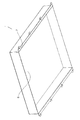
- FIG. 3 is an external perspective view showing an example of the first box-shaped member 1.
- the first box-shaped member 1 is a box-shaped (substantially rectangular parallelepiped) member whose one surface (bottom surface) is open.
- the opening surface of the first box-shaped member 1 is covered with a first surface 2A (see FIG. 4) of a plate-like member 2 described later.
- the waterproof standard required for the first electric circuit is lower than the waterproof standard required for the second electric circuit. Therefore, the inner space 6 of the first box-shaped member 1 is not required to have higher waterproofness than the inner space 14 of the second box-shaped member 3.
- the first box member 1 is provided with a through hole 7 through which the screw 4 shown in FIG. 1 is inserted.
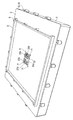
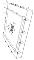
- FIG. 4 is an external perspective view showing an example of the first surface 2 ⁇ / b> A of the plate-like member 2.
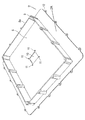
- FIG. 5 is an external perspective view showing an example of the second surface 2 ⁇ / b> B on the back surface of the first surface 2 ⁇ / b> A of the plate-like member 2.
- the plate-like member 2 constitutes the bottom surface of the first box-shaped member 1 and the top surface of the second box-shaped member 3.
- a frame 8 is formed on the first surface 2 ⁇ / b> A of the plate-like member 2.
- the frame 8 may be provided integrally with the first surface 2A, or may be provided so as to be detachable from the first surface 2A.
- the frame body 8 is provided with a screw receiving portion (screw hole) 9 into which the screw 4 shown in FIG. 1 is inserted.
- screw hole screw hole
- an opening 10 that penetrates the first surface 2 ⁇ / b> A and the second surface 2 ⁇ / b> B of the plate-like member 2 is provided in the central portion of the plate-like member 2.
- Four through holes 11 that penetrate the first surface 2A and the second surface 2B of the plate-like member 2 are provided in the peripheral portion of the opening 10.
- a through hole 12 through which the screw 5 shown in FIG. 1 is inserted is provided in the outer peripheral portion of the plate-like member 2.
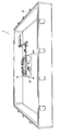
- FIG. 6 is an external perspective view showing an example of the second box-shaped member 3.
- the second box-shaped member 3 is a box-shaped (substantially rectangular parallelepiped) member whose one surface (upper surface) is open.
- the opening surface of the second box-shaped member 3 is covered with the second surface 2B of the plate-like member 2 described above.
- a second electric circuit (not shown) is accommodated in the internal space 14 of the second box-shaped member 3.
- the second electric circuit transmits electric power to and from the first electric circuit housed in the internal space 6 of the first box-type member 1.
- the waterproof standard required for the second electric circuit is higher than the waterproof standard required for the first electric circuit. Therefore, the inner space 14 of the second box-shaped member 3 is required to have a higher waterproof property than the inner space 6 of the first box-shaped member 1.
- a screw receiving member 15 protruding from the bottom surface 3 ⁇ / b> B of the second box-shaped member 3 is provided in the internal space 14 of the second box-shaped member 3.
- the screw receiving member 15 may be provided integrally with the bottom surface 3 ⁇ / b> B, or may be provided detachably with respect to the bottom surface 3 ⁇ / b> B of the second box-shaped member 3.
- the screw receiving member 15 is provided with a positioning receiving portion 16 which is a hole into which a positioning projection 31 (see FIG. 9) of a mold 28 described later is inserted.
- the screw receiving member 15 is provided with a screw receiving portion 17 that is a screw hole into which a screw 33 (see FIG. 10) described later is inserted.
- the outer periphery of the second box-shaped member 3 is provided with a screw receiving portion 19 that is a screw hole into which the screw 5 shown in FIG. 1 is inserted.
- a screw receiving portion 19 that is a screw hole into which the screw 5 shown in FIG. 1 is inserted.
- FIG. 7 is an external perspective view showing an example of a plurality of bus bars in the internal space 14 of the second box-shaped member 3.
- illustration of a mold 28 described later is omitted for convenience of explanation.
- bus bars 20, 21, 22, 23, 25, and 26 are arranged in the internal space 14 of the second box-shaped member 3.
- a through hole 20a is provided at the first end of the bus bar 20, and a through hole 20b is provided at the second end.
- a screw (not shown) is inserted through the through hole 20a.
- the screw is inserted into a screw receiving portion (not shown) of the second electric circuit through the through hole 20a.
- a screw (not shown) is inserted into the through hole 20b.
- the screw is inserted into a through hole (not shown) provided in the through hole 20b and the first electric circuit (or a bus bar (not shown) electrically connected to the first electric circuit).
- the bus bar 20 and the first electric circuit are screwed together.
- a through hole 21a is provided at the first end of the bus bar 21, and a through hole 21b is provided at the second end.
- a screw (not shown) is inserted through the through hole 21a.
- the screw is inserted into a screw receiving portion (not shown) of the second electric circuit through the through hole 21a.
- a screw (not shown) is inserted through the through hole 21b.
- the screw is inserted into a through hole (not shown) provided in the through hole 21b and the first electric circuit (or a bus bar (not shown) electrically connected to the first electric circuit).
- the bus bar 21 and the first electric circuit are screwed.
- a through hole 22a is provided at the first end of the bus bar 22, and a through hole 22b is provided at the second end.
- a through hole 23a is provided at the first end of the bus bar 23, and a through hole 23b is provided at the second end.
- Screws 24 are inserted through the through holes 22a and the through holes 23b.
- the bus bar 22 and the bus bar 23 may be integrally formed.
- a screw (not shown) is inserted through the through hole 23a. The screw is inserted into a screw receiving portion (not shown) of the second electric circuit through the through hole 23a. As a result, the bus bar 23 and the second electric circuit are screwed.
- a through hole 25a is provided at the first end of the bus bar 25, and a through hole 25b is provided at the second end.
- a through hole 26a is provided at the first end of the bus bar 26, and a through hole 26b is provided at the second end.
- a screw 27 is inserted through the through hole 25a and the through hole 26b. Thereby, the bus bar 25 and the bus bar 26 are connected.
- the bus bar 25 and the bus bar 26 may be integrally formed.
- a screw (not shown) is inserted through the through hole 26a. The screw is inserted into a screw receiving portion (not shown) of the second electric circuit through the through hole 26a. As a result, the bus bar 26 and the second electric circuit are screwed.
- a screw (not shown) is inserted into the through hole 25b.
- the screw is inserted into a through hole (not shown) provided in the through hole 25b and the first electric circuit (or a bus bar (not shown) electrically connected to the first electric circuit).
- the bus bar 25 and the first electric circuit are screwed.
- the bus bars 20, 21, 22, 23, 25, and 26, which are a plurality of connecting members, are the first electric circuit that is accommodated in the internal space 6 of the housing 100 and the second electrical space that is accommodated in the internal space 14. Electrical connection with the electrical circuit.
- the bus bars 20, 21, 22, 25 are partially embedded in a resin having insulating properties and heat resistance (for example, polybutylene terephthalate resin or nylon).
- a resin having insulating properties and heat resistance for example, polybutylene terephthalate resin or nylon.
- the resin molded by partially embedding the bus bars 20, 21, 22, 25 is referred to as “mold 28”.
- the bus bars 20, 21, 22, and 25 are insert-molded by the mold 28.
- FIG. 8 is an external perspective view showing the upper surface side of the mold 28.
- FIG. 9 is an external perspective view showing the bottom surface side of the mold 28.
- the mold 28 covers a part of the bus bars 20, 21, 22, and 25.
- the term “part” here includes, for example, a portion below the formation portion of the through holes 20 b, 21 b, 22 b, 25 b and at least a portion inserted through the opening 10.
- the upper surface of the mold 28 is provided with a screw receiving portion 29 which is a screw hole into which a screw 35 (see FIG. 13) described later is inserted.
- the upper surface of the mold 28 refers to a surface facing the second surface 2B of the plate-like member 2.
- a protruding portion 28 a that protrudes above the opening surface of the screw receiving portion 29, closes the opening portion 10 of the plate-like member 2, and penetrates the plate-like member 2 is provided. .
- the protruding portion 28a the portions where the through holes 20b, 21b, 22b, and 25b are formed are exposed to the outside (see FIGS. 12 and 13).
- a groove portion 13 is provided along the outer periphery of the upper surface of the mold 28 in which a waterproof sealing member 34 (see FIG. 11) described later is disposed.
- the groove portion 13 is provided outside the mold 28 from the outer periphery of the protruding portion 28 a, and is provided outside the mold 28 from the screw receiving portion 29.
- a positioning projection 31 is provided on the bottom surface of the mold 28 to be inserted into the positioning receiver 16 (see FIG. 6).
- the mold 28 has a protruding portion 28P on the side surface in which a through hole 30 (screw hole) through which a screw 33 (see FIG. 10) described later is inserted is formed.
- FIG. 10 is an external perspective view showing a state in which the second box-shaped member 3 and the mold 28 are screwed together.
- the positioning projection 31 shown in FIG. 9 is inserted into the positioning receiver 16 shown in FIG.
- the screw 33 is inserted into the screw receiving portion 17 shown in FIG. 6 through the through hole 30 shown in FIG.
- the 2nd box-shaped member 3 and the mold 28 are screwed.
- two through holes 30 and two screw receiving portions 17 are provided, but one or more of each may be provided.
- a waterproof sealing member 34 is disposed in the groove 13 shown in FIG. Inset). Further, the waterproof sealing member 32 is disposed in the groove portion 18 shown in FIG.
- the waterproof sealing members 32 and 34 are elastic members, for example, silicon or ethylene propylene rubber.
- the protruding portion is crushed by the plate-like member 2 by screwing the plate-like member 2 and the second box-shaped member 3 described later and screwing the plate-like member 2 and the mold 28.
- the 2nd surface 2B of the plate-shaped member 2 and the surrounding part of the opening surface of the 2nd box-shaped member 3 closely_contact
- the second surface 2B of the plate-like member 2 and the upper surface of the mold 28 are in close contact with each other without any gap.
- the plate-like member 2 and the second box-shaped member 3 are screwed together using screws 5 as shown in FIG.
- the plate-like member 2 and the mold 28 are screwed together using screws 35.
- the plate-like member 2 and the second box-shaped member 3 are screwed by inserting the screws 5 into the through holes 12 and the screw receiving portions 19 shown in FIG.
- the plate member 2 and the mold 28 are screwed together by inserting the screw 35 into the through hole 11 and the screw receiving portion 29 (see FIGS. 8 and 10) shown in FIG.
- the bus bars 20, 21, 22, 25 are respectively inserted through the openings 10.
- a portion where the through hole 20b is formed in the bus bar 20 a portion where the through hole 21b is formed in the bus bar 21, a portion where the through hole 22b is formed in the bus bar 22, and a portion where the through hole 25b is formed in the bus bar 25 are respectively plate-like members. 2 is located above the first surface 2A. That is, when the 1st box-shaped member 1 is attached to the plate-shaped member 2, each said formation part will be located in the internal space 6 of the 1st box-shaped member 1 shown in FIG.
- the first box-shaped member 1 and the plate-like member 2 are screwed together by inserting the screw 4 into the through hole 7 shown in FIG. 3 and the screw receiving portion 9 shown in FIG. Thereby, the housing
- the plurality of bus bars 20, 21, 22, 25 are inserted into the opening 10.
- a mold 28 formed by insert molding these bus bars closes the opening 10.
- the mold 28 and the plate-like member 2 are in close contact with each other via the waterproof sealing member 32.
- the second box-shaped member 3 and the plate-like member 2 are in close contact with each other via a waterproof sealing member 34. That is, in this way, the plurality of bus bars 20, 21, 22, 25 are converged and inserted through one opening 10. Therefore, even when there are a plurality of bus bars that need to be inserted between spaces (inner spaces 6, 14) having different grades of waterproof standards, it is possible to ensure waterproofness.
- the number of parts for waterproofing and the number of assembling steps can be reduced as compared with the case where an opening corresponding to each of the plurality of bus bars is provided and the opening is closed (waterproof).
- the mold 28 and the second box-shaped member 3 are screwed with screws 33, and the mold 28 and the plate-like member 2 are screwed with screws 35.
- the mold 28 is fastened from both the upper and lower directions. Therefore, a gap is generated between the plate-like member 2 and the mold 28, and the waterproofness of the internal space 14 may be weakened. Therefore, it is conceivable that the mold 28 and the second box-shaped member 3 are fixed with screws 33 and only the mold 28 and the plate-shaped member 2 are fixed with screws 35. That is, it can be considered that the downward fastening is stopped and only the upward fastening is performed.
- bus bars 20, 21, 22, 23, 25, and 26 connected and fixed to the second electric circuit have high rigidity. Therefore, when the mold 28 is lifted upward due to the fastening in the upward direction, there is a possibility that a load is generated at a predetermined portion of these bus bars and the second electric circuit.
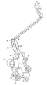
- FIGS. 15 and 16 are external perspective views showing the bus bars 23, 26, 40 to 43 and the wire harnesses 36 to 39.
- FIG. The wire harnesses 36 to 39 are flexible, while the bus bars 23, 26, and 40 to 43 are not flexible.
- a through hole 36a is provided at the first end of the wire harness 36, and a through hole 36b is provided at the second end.
- a through hole 43a is provided at the first end of the bus bar 43, and a through hole 43b is provided at the second end.
- a screw (not shown) is inserted through the through hole 36a. The screw is inserted into the screw receiving portion (not shown) of the second electric circuit through the through hole 36a, so that the wire harness 36 and the second electric circuit are screwed and fixed.
- a screw 44 (see FIG. 18) is inserted through the through hole 36b and the through hole 43a. Thereby, the wire harness 36 and the bus bar 43 are connected.
- a screw (not shown) is inserted through the through hole 43b.
- the screw is inserted into a through hole (not shown) provided in the through hole 43b and the first electric circuit (or a bus bar (not shown) electrically connected to the first electric circuit).
- the bus bar 43 and the first electric circuit are fixed with screws.
- a through hole 37a is provided at the first end of the wire harness 37, and a through hole 37b is provided at the second end.
- a through hole 40a is provided at the first end of the bus bar 40, and a through hole 40b is provided at the second end.
- a screw (not shown) is inserted through the through hole 37a. The screw is inserted into a screw receiving portion (not shown) of the second electric circuit through the through hole 37a, so that the wire harness 37 and the second electric circuit are screwed and fixed.
- a screw 45 (see FIG. 18) is inserted through the through hole 37b and the through hole 40a. Thereby, the wire harness 37 and the bus bar 40 are connected.
- a screw (not shown) is inserted through the through hole 40b.
- the screw is inserted into a through hole (not shown) provided in the through hole 40b and the first electric circuit (or a bus bar (not shown) electrically connected to the first electric circuit), whereby the bus bar 40 and the first electric circuit are connected.
- One electric circuit is fixed with screws.
- a through hole 38a is provided at the first end of the wire harness 38, and a through hole 38b is provided at the second end.
- a through hole 41a is provided at the first end of the bus bar 41, and a through hole 41b is provided at the second end.
- the screw 24 is inserted into the through hole 38 a and the through hole 23 b of the bus bar 23. Thereby, the wire harness 38 and the bus bar 23 are connected.
- a screw 46 (see FIG. 18) is inserted through the through hole 38b and the through hole 41a. Thereby, the wire harness 38 and the bus bar 41 are connected.
- a screw (not shown) is inserted through the through hole 41b. For example, the screw is inserted into a through hole (not shown) provided in the through hole 41b and the first electric circuit (or a bus bar (not shown) electrically connected to the first electric circuit).
- One electric circuit is fixed with screws.
- a through hole 39a is provided at the first end of the wire harness 39, and a through hole 39b is provided at the second end.
- a through hole 42 a is provided at the first end of the bus bar 42, and a through hole 42 b is provided at the second end.
- Screws 27 are inserted through the through holes 39a and the through holes 26b of the bus bar 26. Thereby, the wire harness 39 and the bus bar 26 are connected.
- a screw 47 (see FIG. 18) is inserted through the through hole 39b and the through hole 42a. Thereby, the wire harness 39 and the bus bar 42 are connected.
- a screw (not shown) is inserted through the through hole 42b. For example, the screw is inserted into a through-hole (not shown) provided in the through-hole 42b and the first electric circuit (or a bus bar (not shown) electrically connected to the first electric circuit).
- One electric circuit is fixed with screws.
- the bus bar 42, the wire harness 39, and the bus bar 26 also constitute one of the connecting members that electrically connect the first electric circuit and the second electric circuit.
- the bus bar 42 is a first bus bar that is inserted into the opening 10 and connected to the first electric circuit.
- the bus bar 26 is a second bus bar connected to the second electric circuit.
- the wire harness 39 has a first end connected to the bus bar 42 and a second end connected to the bus bar 26.
- the mold 28 covers a part of the bus bar 42 as shown in FIG.
- the bus bars 40 to 43 are inserted so that they can be screwed to the through holes 40a to 43a and the through holes 40b to 43b with an insulating and heat resistant resin (for example, polybutylene terephthalate resin or nylon). Molded (see FIGS. 17 and 18).
- the shape of the mold 28b formed by insert molding is substantially the same as that of the mold 28 described in the first embodiment.
- FIG. 17 is an external perspective view showing the upper surface of the mold 28b.
- FIG. 18 is an external perspective view showing the bottom surface of the mold 28b.
- Mold 28b partially covers bus bars 40-43.
- the part to be covered includes, for example, a part that is located between the through holes 40 b, 41 b, 42 b, 43 b and the through holes 40 a, 41 a, 42 a, 43 a and is inserted into the opening 10.
- the through-hole 30 (refer FIG. 8, FIG. 9) demonstrated in Embodiment 1 is not provided in the mold 28b.
- the screw receiving member 15 of the second box-shaped member 3 is not provided with the screw receiving portion 17 (see FIGS. 6 and 7).
- the mold 28 and the second box-shaped member 3 are screwed with the screws 33, but in the present embodiment, the mold 28 b and the second box-shaped The member 3 is not screwed.
- the position of the mold 28b is temporarily fixed by inserting the positioning protrusion 31 shown in FIG. 18 into the positioning receiving portion 16 shown in FIG.
- the mold 28b since the mold 28b is not fastened to the second box-shaped member 3, it can be displaced in the vertical direction.
- the screw receiving portion 17 is shown in FIG. 6, the screw receiving portion 17 is not necessary in the present embodiment.
- the plate-like member 2 is placed on the second box-shaped member 3 as shown in FIG.
- the protrusion 28 a is inserted into the opening 10 of the plate-like member 2 and closes the opening 10. Further, the position of the through hole 11 of the plate-like member 2 and the position of the screw receiving portion 29 (see FIG. 17) of the mold 28 coincide with each other.
- the plate-like member 2 and the mold 28b are screwed and fixed using screws 35 as shown in FIG. Specifically, the plate member 2 and the mold 28b are screwed by inserting the screw 35 into the through hole 11 and the screw receiving portion 29 (see FIG. 17) shown in FIG.
- the mold 28b and the second box-shaped member 3 are not screwed as described above, when the screw 35 is screwed in, the mold 28b is positioned so that the protruding portion 28a protrudes from the plate-like member 2. Displace in the direction. Thereby, the waterproof sealing member 34 provided along the outer periphery of the mold 28b is reliably crushed by the plate-like member 2 and the mold 28b. As a result, the 2nd surface 2B of the plate-shaped member 2 and the upper surface (surface other than the protrusion part 28a) of the mold 28b closely_contact
- flexible wire harnesses 36 to 39 are interposed between the bus bars 40 to 43 and the second electric circuit. Therefore, even if the mold 28b is displaced in the upward direction, the wire harnesses 36 to 39 can absorb misalignment due to the displacement of the mold 28b. As a result, the generation of loads on the bus bars 23 and 26 and the second electric circuit can be suppressed.
- a connection member is used in which a bus bar as a first connection member having no flexibility and a wire harness as a second connection member having flexibility are connected.
- the mold 28b and the plate-like member 2 are allowed to be lifted upward by screwing, and at a predetermined location of the bus bar or the second electric circuit or a predetermined location of the housing 100. Generation of load can be suppressed.
- it may replace with a bus bar and may use the other 1st connection member which does not have flexibility, for example, a metal bar.
- another flexible second connection member such as a flexible wiring board may be used.
- Embodiment 3 Next, Embodiment 3 will be described with reference to FIGS.
- FIG. 19 is an external perspective view showing an example of the housing 101.
- the housing 101 includes a lid member 50 and a second box-shaped member 3 (hereinafter referred to as a box-shaped member 3).
- the plate-shaped member 2 has an internal space that is a first space and an internal space that is a second space. Divided into spaces.
- the plate-like member 2 has a frame body 8a.
- the frame body 8a also constitutes a part of the housing 101.
- the first space is, for example, the internal space 6 (see FIG. 21) of the frame 8a
- the second space is, for example, the internal space 14 (see FIG. 6) of the box-shaped member 3.
- the lid member 50 and the frame body 8a are fixed by screwing with a plurality of screws 4.
- the box-shaped member 3 and the plate-like member 2 are fixed by screwing with a plurality of screws 5.
- the lid member 50, the plate-like member 2, and the box-shaped member 3 are made of metal, for example.
- FIG. 20 is an external perspective view showing an example of the lid member 50.
- the lid member 50 is a plate-like member, and a through-hole 51 through which the screw 4 shown in FIG.
- FIG. 21 is an external perspective view showing an example of the first surface 2 ⁇ / b> A of the plate-like member 2.
- the plate-like member 2 as a partition member partitions the internal space 6 of the frame body 8a from the internal space 14 of the box-shaped member 3 (see FIG. 6).
- the first surface 2 ⁇ / b> A of the plate-like member 2 faces the internal space 6, and the second surface of the plate-like member 2 (the back surface of the first surface 2 ⁇ / b> A) faces the internal space 14.
- the appearance of the second surface of the plate-like member 2 is the same as that shown in FIG. 6 described in the first embodiment.
- a frame body 8a is formed on the first surface 2A of the plate member 2.
- the frame body 8a may be provided integrally with the first surface 2A, or may be provided so as to be detachable from the first surface 2A.
- the frame body 8a is taller than the frame body 8 described in the first embodiment (see, for example, FIG. 4). That is, the length of the frame 8 a in the direction sandwiched between the lid member 50 and the box-shaped member 3 is the length of the frame 8 in the direction sandwiched between the first box-shaped member 1 and the second box-shaped member 3. Bigger than that.
- the space surrounded by the frame body 8 a, the lid member 50, and the plate-like member 2 is the internal space 6.
- a first electric circuit (not shown) is accommodated, as in the first and second embodiments.
- the first electric circuit transmits electric power to and from a second electric circuit (not shown) accommodated in an internal space 14 (see FIG. 6) of the box-shaped member 3 described later.
- the waterproof standard required for the first electric circuit is lower than the waterproof standard required for the second electric circuit. Therefore, the inner space 6 surrounded by the frame body 8 a is not required to have higher waterproofness than the inner space 14 of the box-shaped member 3.
- the frame body 8a is provided with a screw receiving portion (screw hole) 9 into which the screw 4 shown in FIG. 19 is inserted.
- screw hole screw hole
- the lid member 50 and the frame body 8a are fixed by screwing. Thereby, the opening surface of the frame 8a is covered with the lid member 50.
- an opening 10 that penetrates the first surface 2 ⁇ / b> A and the second surface of the plate-like member 2 is provided in the central portion of the plate-like member 2. Further, four through holes 11 penetrating the first surface 2 ⁇ / b> A and the second surface of the plate-like member 2 are provided in the peripheral portion of the opening 10.
- the plate-like member 2 on which the frame body 8a is formed is used, but the present invention is not limited to this.
- a box-shaped member having an open upper surface hereinafter referred to as a third box-shaped member
- the upper surface (opening surface) of the third box-shaped member is covered with the lid member 50, and the bottom surface of the third box-shaped member covers the upper surface (opening surface) of the box-shaped member 3.
- the bottom surface of the third box-shaped member functions as a partition member that partitions the internal space of the third box-shaped member and the internal space 14 of the box-shaped member 3.
- connection method of predetermined members is not limited to screwing.
- the bus bar and the wire harness may be fixed by caulking.
- the first electric circuit connected to the bus bar 20 (or bus bar 43), bus bar 21 (or bus bar 40), bus bar 22 (or bus bar 41), bus bar 25 (or bus bar 42) is common 1
- a plurality of different first electric circuits may be used.
- the bus bar 20 (or bus bar 43) and the bus bar 21 (or bus bar 40) are connected to the first electric circuit A
- the bus bar 22 (or bus bar 41) and the bus bar 25 (or bus bar 42) are connected to the first electric circuit.
- a first electric circuit B different from A may be connected.
- the waterproof standard required for the second electric circuit is higher than the waterproof standard required for the first electric circuit, and the internal space 14 of the second box-shaped member 3 is the first box.
- the reverse may be possible. That is, the waterproof standard required for the first electric circuit is higher than the waterproof standard required for the second electric circuit, and the internal space 6 of the first box-shaped member 1 is located inside the second box-shaped member 3. The case where the waterproofness higher than the space 14 is requested
- a wire harness is used instead of the bus bar 23 and the bus bar 26, and a bus bar (for example, FIG. 7) is used instead of the wire harness 38 and the bus bar 41, and the wire harness 39 and the bus bar 42.
- a bus bar for example, FIG. 7
- the bus bars 22 and 25 shown in FIG. That is, a flexible wire harness may be interposed between the insert-molded bus bars 40 to 43 and the second electric circuit.
- the present disclosure can be applied to all techniques for electrically connecting electrical circuits.
Landscapes
- Engineering & Computer Science (AREA)
- Architecture (AREA)
- Civil Engineering (AREA)
- Structural Engineering (AREA)
- Mechanical Engineering (AREA)
- Casings For Electric Apparatus (AREA)
- Connection Or Junction Boxes (AREA)
Abstract
電気接続構造体は、開口部が設けられた仕切り部材と、筐体と、複数の接続部材と、モールドとを有する。仕切り部材は筐体の内部を第1空間と第2空間に分けている。複数の接続部材は、第1空間に収容される第1電気回路と第2空間に収容される第2電気回路とを電気的に接続している。モールドは、仕切り部材を貫通する開口部を閉塞している。仕切り部材は、第1空間に面する第1面と、その裏側で第2空間に面する第2面を有する。複数の接続部材は、モールドを介して、第2空間から第1空間を貫通している。モールドにおける、第2面に相対する面の周囲部分と、第2面とが、防水用封止部材を介して密着している。
Description
本開示は、2つの電気回路を電気的に接続する電気接続構造体に関する。
例えば特許文献1には、1つの筐体の内部に配置された第1電気回路(例えば、インバータ)と第2電気回路(例えば、ジャンクションボックス)とを1つのバスバーによって電気的に接続する構造が開示されている。この構造では、仕切り部材が筐体の内部を第1空間と第2空間に分け、第1空間に第1電気回路が配置され、第2空間に第2電気回路が配置される。仕切り部材には開口部が設けられ、バスバーはこの開口部を貫いている。
本開示は、防水規格の等級が異なる空間にそれぞれ配置された2つの電気回路を複数のバスバーによって電気的に接続する電気接続構造体を提供する。
本開示の一態様に係る電気接続構造体は、開口部が設けられた仕切り部材と、筐体と、複数の接続部材と、モールドとを有する。筐体の内部は、仕切り部材によって第1空間と第2空間に分けられている。複数の接続部材は、第1空間に収容される第1電気回路と第2空間に収容される第2電気回路とを電気的に接続している。モールドは、仕切り部材の開口部を閉塞している。仕切り部材は、第1空間に面する第1面と、その裏面であり第2空間に面する第2面を有する。開口部は、第1面と第2面とを貫通している。複数の接続部材は、モールドを介して、第2空間から第1空間を貫通している。モールドにおける、第2面に相対する面の周囲部分と、第2面とが、防水用封止部材を介して密着している。
本開示の電気接続構造体においては、防水のための部品点数および組立工数を削減できる。
本開示の実施の形態の説明に先立ち、従来の技術における問題点を簡単に説明する。特許文献1の構造では、防水された1つの筐体内に第1空間と第2空間が作られている。そのため、第1空間と第2空間との間(仕切り部材に設けられた開口部)に防水構造は不要である。一方、第1空間と第2空間とに要求される防水規格の等級が異なる場合、防水用封止部材を用いて仕切り部材の開口部を封止する必要がある。さらに、複数のバスバーにより第1電気回路と第2電気回路とを接続する場合、各バスバーに対応する複数の開口部を仕切り部材に設け、各開口部を防水用封止部材により封止する必要がある。したがって、部品点数および組立工数が増加する。
以下、本開示の電気接続構造体の種々の実施の形態について、図面を参照して説明する。本開示の電気接続構造体は、以下の実施の形態で説明する筐体100とその内部の構成(例えば、バスバー、モールド等)を含む。なお、先行する実施の形態と同様の構成要素については同一符号を付し、それらの説明は省略することがある。
(実施の形態1)
図1は、筐体100の一例を示す外観斜視図である。まず、図1を参照しながら、実施の形態1に係る筐体100の全体構成について説明する。
図1は、筐体100の一例を示す外観斜視図である。まず、図1を参照しながら、実施の形態1に係る筐体100の全体構成について説明する。
筐体100は、第1箱型部材1、第2箱型部材3を有する。筐体100の内部は、仕切り部材としての板状部材2によって内部が第1空間(例えば、後述の内部空間6)と第2空間(後述の内部空間14)に分けられている。第1箱型部材1と板状部材2は、複数のネジ4によりネジ留めされる。第2箱型部材3と板状部材2は、複数のネジ5によりネジ留めされる。第1箱型部材1、板状部材2、第2箱型部材3は、例えば、金属製である。
図2は、筐体100に収容された第1電気回路80と第2電気回路90を示す概念図である。第1箱型部材1の内部空間6に収容され、第2電気回路90は第2箱型部材3の内部空間14に収容される。内部空間6は、筐体100の第1空間の一例であり、内部空間14は、筐体100の第2空間の一例である。第1電気回路80は、第2電気回路90との間で、電力を伝達する。
次に、図3を参照しながら、第1箱型部材1について説明する。図3は、第1箱型部材1の一例を示す外観斜視図である。
第1箱型部材1は、一面(底面)が開口した箱型(略直方体状)の部材である。第1箱型部材1の開口面は、後述する板状部材2の第1面2A(図4参照)によって被覆される。
本実施の形態では例として、第1電気回路に求められる防水規格の等級は、第2電気回路に求められる防水規格の等級よりも低い。よって、第1箱型部材1の内部空間6には、第2箱型部材3の内部空間14よりも高い防水性は要求されない。
また、図3に示すように、第1箱型部材1には、図1に示したネジ4が挿通される貫通孔7が設けられている。
次に、図4、図5を参照しながら、板状部材2について説明する。図4は、板状部材2の第1面2Aの一例を示す外観斜視図である。図5は、板状部材2の第1面2Aの裏面の第2面2Bの一例を示す外観斜視図である。
図4、図5に示す板状部材2は、第1箱型部材1の内部空間6と第2箱型部材3の内部空間14とを仕切る板状の部材(仕切り部材)である。板状部材2は、第1箱型部材1の底面を構成するとともに、第2箱型部材3の上面を構成する。
図4に示すように、板状部材2の第1面2Aには、枠体8が形成されている。枠体8は、第1面2Aと一体的に設けられてもよいし、第1面2Aに対して着脱可能に設けられてもよい。
枠体8には、図1に示したネジ4が挿入されるネジ受け部(ネジ孔)9が設けられている。ネジ4が貫通孔7を介してネジ受け部9に挿入されることにより、第1箱型部材1と板状部材2とがネジ留め固定される。
また、図4、図5に示すように、板状部材2の中央部分には、板状部材2の第1面2Aと第2面2Bとを貫通する開口部10が設けられている。開口部10の周囲部分には、板状部材2の第1面2Aと第2面2Bとを貫通する4つの貫通孔11が設けられている。
また、図4、図5に示すように、板状部材2の外周部分には、図1に示したネジ5が挿通される貫通孔12が設けられている。
次に、図6を参照しながら、第2箱型部材3について説明する。図6は、第2箱型部材3の一例を示す外観斜視図である。
第2箱型部材3は、一面(上面)が開口した箱型(略直方体状)の部材である。第2箱型部材3の開口面は、上述した板状部材2の第2面2Bによって被覆される。
第2箱型部材3の内部空間14には、第2電気回路(図示略)が収容される。第2電気回路は、第1箱型部材1の内部空間6に収容される第1電気回路との間で、電力を伝達する。
本実施の形態では一例として、第2電気回路に求められる防水規格の等級は、第1電気回路に求められる防水規格の等級よりも高い。よって、第2箱型部材3の内部空間14には、第1箱型部材1の内部空間6よりも高い防水性が要求される。
また、図6に示すように、第2箱型部材3の内部空間14には、第2箱型部材3の底面3Bから突出したネジ受け部材15が設けられている。ネジ受け部材15は、底面3Bと一体的に設けられてもよいし、第2箱型部材3の底面3Bに対して着脱可能に設けられてもよい。
ネジ受け部材15には、後述するモールド28の位置決め用突起部31(図9参照)が挿入される孔である位置決め用受け部16が設けられている。
また、ネジ受け部材15には、後述するネジ33(図10参照)が挿入されるネジ孔であるネジ受け部17が設けられている。
また、図6に示すように、第2箱型部材3の開口面の周囲部分には、後述する防水用封止部材32(図11参照)が配置される溝部18が設けられている。
第2箱型部材3の外周部分には、図1に示したネジ5が挿入されるネジ孔であるネジ受け部19が設けられている。ネジ5が板状部材2の貫通孔12を介してネジ受け部19に挿入されることにより、第2箱型部材3と板状部材2とがネジ留めされ、固定される。
次に、図7を参照しながら、第1電気回路と第2電気回路とを電気的に接続する複数のバスバーについて説明する。図7は、第2箱型部材3の内部空間14における複数のバスバーの一例を示す外観斜視図である。なお、図7では、説明の便宜上、後述するモールド28の図示を省略している。
第2箱型部材3の内部空間14には、バスバー20、21、22、23、25、26が配置される。
まず、バスバー20について説明する。バスバー20の第1端には貫通孔20aが設けられており、第2端には貫通孔20bが設けられている。貫通孔20aには図示しないネジが挿通される。そのネジが貫通孔20aを介して第2電気回路のネジ受け部(図示略)に挿入される。その結果、バスバー20と第2電気回路とがネジ留めされる。貫通孔20bには図示しないネジが挿通される。例えば、そのネジが貫通孔20bと第1電気回路(または、第1電気回路と電気的に接続された図示しないバスバー)に設けられた図示しない貫通孔に挿通される。その結果、バスバー20と第1電気回路とがネジ留めされる。
次に、バスバー21について説明する。バスバー21の第1端には貫通孔21aが設けられており、第2端には貫通孔21bが設けられている。貫通孔21aには図示しないネジが挿通される。そのネジが貫通孔21aを介して第2電気回路のネジ受け部(図示略)に挿入される。その結果、バスバー21と第2電気回路とがネジ留めされる。貫通孔21bには図示しないネジが挿通される。例えば、そのネジが貫通孔21bと第1電気回路(または、第1電気回路と電気的に接続された図示しないバスバー)に設けられた図示しない貫通孔に挿通される。その結果、バスバー21と第1電気回路とがネジ留めされる。
次に、バスバー22、23について説明する。バスバー22の第1端には貫通孔22aが設けられており、第2端には貫通孔22bが設けられている。また、バスバー23の第1端には貫通孔23aが設けられており、第2端には貫通孔23bが設けられている。貫通孔22aと貫通孔23bにはネジ24が挿通される。これにより、バスバー22とバスバー23が接続される。なお、バスバー22とバスバー23は、一体的に形成されていてもよい。貫通孔23aには図示しないネジが挿通される。そのネジが貫通孔23aを介して第2電気回路のネジ受け部(図示略)に挿入される。その結果、バスバー23と第2電気回路とがネジ留めされる。貫通孔22bには図示しないネジが挿通される。例えば、そのネジが貫通孔22bと第1電気回路(または、第1電気回路と電気的に接続された図示しないバスバー)に設けられた図示しない貫通孔に挿通される。その結果、バスバー22と第1電気回路とがネジ留めされる。
次に、バスバー25、26について説明する。バスバー25の第1端には貫通孔25aが設けられており、第2端には貫通孔25bが設けられている。バスバー26の第1端には貫通孔26aが設けられており、第2端には貫通孔26bが設けられている。貫通孔25aと貫通孔26bにはネジ27が挿通される。これにより、バスバー25とバスバー26が接続される。なお、バスバー25とバスバー26は、一体的に形成されていてもよい。貫通孔26aには図示しないネジが挿通される。そのネジが貫通孔26aを介して第2電気回路のネジ受け部(図示略)に挿入される。その結果、バスバー26と第2電気回路とがネジ留めされる。
第2電気回路の回路設計や配置最適化のために、第1電気回路と電気的に接続する第2電気回路(のネジ受け部)が、開口部10から離れた位置に設けられることがある。そのため、バスバー23、26を用いて配線を延設させている。すなわち、バスバー20とバスバー21とは、互いに対称的に設けられており、同じ長さである。一方、バスバー22はバスバー20、21より長く、バスバー25はバスバー20、21と同じ長さかまたは短い。このように、バスバー20~22、25のうちの少なくとも1つの長さは、それ以外の長さと異なっていてもよい。
貫通孔25bには図示しないネジが挿通される。例えば、そのネジが貫通孔25bと第1電気回路(または、第1電気回路と電気的に接続された図示しないバスバー)に設けられた図示しない貫通孔に挿通される。その結果、バスバー25と第1電気回路とがネジ留めされる。
以上のように、複数の接続部材であるバスバー20、21、22、23、25、26は、筐体100の内部空間6に収容される第1電気回路と内部空間14に収容される第2電気回路とを電気的に接続する。
バスバー20、21、22、25は、絶縁性および耐熱性を有する樹脂(例えば、ポリブチレンテレフタレート樹脂、または、ナイロン等)に部分的に埋設される。本実施の形態では、バスバー20、21、22、25を部分的に埋設して成形された樹脂を「モールド28」と呼ぶ。このように、バスバー20、21、22、25はモールド28によりインサート成形される。
次に、図8、図9を参照しながら、モールド28について説明する。図8は、モールド28の上面側を示す外観斜視図である。図9は、モールド28の底面側を示す外観斜視図である。
図8、図9に示すように、モールド28は、バスバー20、21、22、25の一部分を被覆する。ここでいう一部分とは、例えば、貫通孔20b、21b、22b、25bの形成部分の下方であって、少なくとも開口部10に挿通される部分を含む。
図8に示すように、モールド28の上面には、後述するネジ35(図13参照)が挿入されるネジ孔であるネジ受け部29が設けられている。なお、モールド28の上面とは、板状部材2の第2面2Bに相対する面をいう。
また、モールド28の上面には、ネジ受け部29の開口面よりも上方に突出し、板状部材2の開口部10を閉塞しつつ、板状部材2を貫通する突出部28aが設けられている。突出部28aにおいて、貫通孔20b、21b、22b、25bの形成部分は、外部に露出している(図12、図13参照)。
さらに、モールド28の上面には、モールド28の上面の外周に沿って、後述する防水用封止部材34(図11参照)が配置される溝部13が設けられている。溝部13は、突出部28aの外周よりもモールド28の外側に設けられ、また、ネジ受け部29よりもモールド28の外側に設けられる。
図9に示すように、モールド28の底面には、上述した位置決め用受け部16(図6参照)に挿入される位置決め用突起部31が設けられている。
図8、図9に示すように、モールド28は、後述するネジ33(図10参照)が挿通される貫通孔30(ネジ孔)が形成された突出部28Pを側面に有する。
次に、図10を参照しながら、モールド28と第2箱型部材3とのネジ留め構造について説明する。図10は、第2箱型部材3とモールド28とがネジ留めされた状態を示す外観斜視図である。
まず、図9に示した位置決め用突起部31を、図6に示した位置決め用受け部16に挿入する。そして、図10に示すように、ネジ33を、図9に示した貫通孔30を介して、図6に示したネジ受け部17に挿入する。これにより、第2箱型部材3とモールド28とがネジ留めされる。なお、貫通孔30とネジ受け部17とは、それぞれ2つ設けられているが、各1つ以上設けられていればよい。
次に、図10~図14を参照しながら、第2箱型部材3と板状部材2とのネジ留め構造について説明する。図11は、第2箱型部材3とモールド28とにそれぞれ、防水用封止部材32、34が配置された状態を示す外観斜視図である。図12は、第2箱型部材3に板状部材2が載せられた状態を示す外観斜視図である。図13は、板状部材2とモールド28とがネジ留め固定され、板状部材2と第2箱型部材3がネジ留め固定された状態を示す外観斜視図である。図14は、図13に示したモールド28の図示を省略した外観斜視図である。
図10に示したように第2箱型部材3とモールド28とをネジ33によりネジ留めした後、図11に示すように、図10に示した溝部13に防水用封止部材34を配置(はめ込み)する。また、図10に示した溝部18に防水用封止部材32を配置する。防水用封止部材32、34は、弾性部材であり、例えば、シリコンまたはエチレンプロピレンゴムである。
溝部13、18にそれぞれ配置された防水用封止部材32、34は、図11に示すように溝部13、18から上方にはみ出す。このはみ出した部分は、後述する板状部材2と第2箱型部材3とをネジ留めし、板状部材2とモールド28とをネジ留めすることにより、板状部材2に押しつぶされる。これにより、板状部材2の第2面2Bと第2箱型部材3の開口面の周囲部分とが隙間無く密着する。また、板状部材2の第2面2Bとモールド28の上面(突出部28a以外の面)とが隙間無く密着する。
図11に示したように防水用封止部材32、34を配置した後、図12に示すように、板状部材2を第2箱型部材3に載置する。このとき、突出部28aは、板状部材2の開口部10に挿入され、開口部10を閉塞する。このとき、板状部材2の貫通孔11の位置と、モールド28のネジ受け部29(図8、図10参照)の位置とが一致する。また、板状部材2の貫通孔12の位置と、第2箱型部材3のネジ受け部19の位置とが一致する。
図12に示したように第2箱型部材3に板状部材2を載置した後、図13に示すように、ネジ5を用いて板状部材2と第2箱型部材3とをネジ留めし、ネジ35を用いて板状部材2とモールド28とのネジ留めする。具体的には、ネジ5を、図12に示した貫通孔12とネジ受け部19に挿入することにより、板状部材2と第2箱型部材3とをネジ留めする。また、ネジ35を、図12に示した貫通孔11とネジ受け部29(図8、図10参照)に挿入することにより、板状部材2とモールド28とをネジ留めする。
なお、貫通孔11とネジ受け部29とは、それぞれ4つ設けられているが、各1つ以上設けられていればよい。
図14に示すように、バスバー20、21、22、25は、それぞれ、開口部10に挿通されている。また、バスバー20における貫通孔20bの形成部分、バスバー21における貫通孔21bの形成部分、バスバー22における貫通孔22bの形成部分、および、バスバー25における貫通孔25bの形成部分は、それぞれ、板状部材2の第1面2Aよりも上方に位置している。すなわち、板状部材2に第1箱型部材1を取り付けると、上記各形成部分は、図3に示す第1箱型部材1の内部空間6に位置する。
次に、図1を参照しながら、第1箱型部材1と板状部材2とのネジ留め構造について説明する。
図13に示したように板状部材2と第2箱型部材3とをネジ留めし、板状部材2とモールド28とをネジ留めした後、図1に示すように、第1箱型部材1を板状部材2に載置する。このとき、第1箱型部材1の貫通孔7(図3参照)の位置と、板状部材2の枠体8に形成されたネジ受け部9(図13参照)の位置とが一致する。
そして、ネジ4を、図3に示した貫通孔7と図13に示したネジ受け部9に挿入することにより、第1箱型部材1と板状部材2とをネジ留めする。これにより、図1に示した筐体100が完成する。
以上説明したように、本実施の形態によれば、開口部10に複数のバスバー20、21、22、25が挿通される。それらのバスバーをインサート成形したモールド28が開口部10を閉塞する。さらにモールド28と板状部材2とが防水用封止部材32を介して密着している。また、第2箱型部材3と板状部材2とが防水用封止部材34を介して密着している。すなわち、このように、複数のバスバー20、21、22、25を収束させて1つの開口部10から挿通させる。そのため、防水規格の等級が異なる空間(内部空間6、14)の間を挿通させる必要があるバスバーが複数ある場合でも、防水性を確保することが可能である。また、複数のバスバー各々に対応する開口部を設け、当該開口部を閉塞(防水)させる場合に比べて、防水のための部品点数および組立工数を削減することができる。
(実施の形態2)
次に、実施の形態2について説明する。実施の形態1では、ネジ33によりモールド28と第2箱型部材3とをネジ留めし、かつ、ネジ35によりモールド28と板状部材2とをネジ留めしている。この場合、モールド28は上下方向の両方から締結される。そのため、板状部材2とモールド28との間に空隙が生じ、内部空間14の防水性が弱くなるおそれがある。そこで、ネジ33によるモールド28と第2箱型部材3とのネジ留めを止めて、ネジ35によるモールド28と板状部材2とのネジ留めのみにすることが考えられる。すなわち、下方向の締結を止めて、上方向の締結のみにすることが考えられる。しかしながら、第2電気回路に接続固定されているバスバー20、21、22、23、25、26は高い剛性を有する。そのため、上方向の締結により、モールド28が上方向に持ち上がった際に、これらのバスバーや第2電気回路の所定箇所に負荷が生じるおそれがある。
次に、実施の形態2について説明する。実施の形態1では、ネジ33によりモールド28と第2箱型部材3とをネジ留めし、かつ、ネジ35によりモールド28と板状部材2とをネジ留めしている。この場合、モールド28は上下方向の両方から締結される。そのため、板状部材2とモールド28との間に空隙が生じ、内部空間14の防水性が弱くなるおそれがある。そこで、ネジ33によるモールド28と第2箱型部材3とのネジ留めを止めて、ネジ35によるモールド28と板状部材2とのネジ留めのみにすることが考えられる。すなわち、下方向の締結を止めて、上方向の締結のみにすることが考えられる。しかしながら、第2電気回路に接続固定されているバスバー20、21、22、23、25、26は高い剛性を有する。そのため、上方向の締結により、モールド28が上方向に持ち上がった際に、これらのバスバーや第2電気回路の所定箇所に負荷が生じるおそれがある。
以下、このような問題を解決する実施の形態2に係る電気接続構造体の構成を説明する。
まず、図15、図16を参照しながら、本実施の形態に係るバスバーとワイヤーハーネスとの接続構成の一例について説明する。図15、図16は、バスバー23、26、40~43とワイヤーハーネス36~39を示す外観斜視図である。ワイヤーハーネス36~39は可撓性を有する一方、バスバー23、26、40~43は可撓性を有しない。
まず、ワイヤーハーネス36とバスバー43について説明する。ワイヤーハーネス36の第1端には貫通孔36aが設けられており、第2端には貫通孔36bが設けられている。バスバー43の第1端には貫通孔43aが設けられており、第2端には貫通孔43bが設けられている。貫通孔36aには図示しないネジが挿通される。そのネジが貫通孔36aを介して第2電気回路のネジ受け部(図示略)に挿入されることにより、ワイヤーハーネス36と第2電気回路とがネジ留め固定される。貫通孔36bと貫通孔43aにはネジ44(図18参照)が挿通される。これにより、ワイヤーハーネス36とバスバー43とが接続される。貫通孔43bには図示しないネジが挿通される。例えば、そのネジが貫通孔43bと第1電気回路(または、第1電気回路と電気的に接続された図示しないバスバー)に設けられた図示しない貫通孔に挿通される。この構成により、バスバー43と第1電気回路とがネジ留め固定される。
次に、ワイヤーハーネス37とバスバー40について説明する。ワイヤーハーネス37の第1端には貫通孔37aが設けられており、第2端には貫通孔37bが設けられている。バスバー40の第1端には貫通孔40aが設けられており、第2端には貫通孔40bが設けられている。貫通孔37aには図示しないネジが挿通される。そのネジが貫通孔37aを介して第2電気回路のネジ受け部(図示略)に挿入されることにより、ワイヤーハーネス37と第2電気回路とがネジ留め固定される。貫通孔37bと貫通孔40aにはネジ45(図18参照)が挿通される。これにより、ワイヤーハーネス37とバスバー40が接続される。貫通孔40bには図示しないネジが挿通される。例えば、そのネジが貫通孔40bと第1電気回路(または、第1電気回路と電気的に接続された図示しないバスバー)に設けられた図示しない貫通孔に挿通されることにより、バスバー40と第1電気回路とがネジ留め固定される。
次に、ワイヤーハーネス38とバスバー41、23について説明する。ワイヤーハーネス38の第1端には貫通孔38aが設けられており、第2端には貫通孔38bが設けられている。バスバー41の第1端には貫通孔41aが設けられており、第2端には貫通孔41bが設けられている。貫通孔38aとバスバー23の貫通孔23bにネジ24が挿通される。これにより、ワイヤーハーネス38とバスバー23が接続される。貫通孔38bと貫通孔41aにはネジ46(図18参照)が挿通される。これにより、ワイヤーハーネス38とバスバー41が接続される。貫通孔41bには図示しないネジが挿通される。例えば、そのネジが貫通孔41bと第1電気回路(または、第1電気回路と電気的に接続された図示しないバスバー)に設けられた図示しない貫通孔に挿通されることにより、バスバー41と第1電気回路とがネジ留め固定される。
このように、バスバー41とワイヤーハーネス38とバスバー23とが、第1電気回路と第2電気回路とを電気的に接続する接続部材の1つを構成している。バスバー41は、開口部10に挿通されるとともに第1電気回路に接続される第1バスバーである。バスバー23は第2電気回路と接続される第2バスバーである。ワイヤーハーネス38は、バスバー41と接続された第1端と、バスバー23と接続された第2端とを有する。モールド28は、図17に示すようにバスバー41の一部を被覆する。
次に、ワイヤーハーネス39とバスバー42、26について説明する。ワイヤーハーネス39の第1端には貫通孔39aが設けられており、第2端には貫通孔39bが設けられている。バスバー42の第1端には貫通孔42aが設けられており、第2端には貫通孔42bが設けられている。貫通孔39aとバスバー26の貫通孔26bにネジ27が挿通される。これにより、ワイヤーハーネス39とバスバー26が接続される。貫通孔39bと貫通孔42aにはネジ47(図18参照)が挿通される。これにより、ワイヤーハーネス39とバスバー42が接続される。貫通孔42bには図示しないネジが挿通される。例えば、そのネジが貫通孔42bと第1電気回路(または、第1電気回路と電気的に接続された図示しないバスバー)に設けられた図示しない貫通孔に挿通されることにより、バスバー42と第1電気回路とがネジ留め固定される。
このように、バスバー42とワイヤーハーネス39とバスバー26ともまた、第1電気回路と第2電気回路とを電気的に接続する接続部材の1つを構成している。バスバー42は、開口部10に挿通されるとともに第1電気回路に接続される第1バスバーである。バスバー26は第2電気回路と接続される第2バスバーである。ワイヤーハーネス39は、バスバー42と接続された第1端と、バスバー26と接続された第2端とを有する。モールド28は、図17に示すようにバスバー42の一部を被覆する。
バスバー40~43は、絶縁性および耐熱性を有する樹脂(例えば、ポリブチレンテレフタレート樹脂、または、ナイロン等)により、貫通孔40a~43a、貫通孔40b~43bにネジ留めが可能となるようにインサート成形される(図17、図18参照)。インサート成形により成形されたモールド28bの形状は、実施の形態1で説明したモールド28とほぼ同じである。
次に、図17、図18を参照しながら、モールド28bについて説明する。図17は、モールド28bの上面を示す外観斜視図である。図18は、モールド28bの底面を示す外観斜視図である。
モールド28bは、バスバー40~43を部分的に被覆する。被覆される部分は、例えば、貫通孔40b、41b、42b、43bと貫通孔40a、41a、42a、43aとの間に位置する部分であって、開口部10に挿通される部分を含む。
モールド28bには、実施の形態1で説明した貫通孔30(図8、図9参照)は設けられていない。また、図示は省略するが、第2箱型部材3のネジ受け部材15には、ネジ受け部17(図6、図7参照)は設けられていない。実施の形態1では、図10を参照して説明したようにネジ33によりモールド28と第2箱型部材3とをネジ留めしているが、本実施の形態では、モールド28bと第2箱型部材3とをネジ留めしない。
具体的には、まず、図18に示した位置決め用突起部31を、図6に示した位置決め用受け部16に挿入することにより、モールド28bの位置が仮固定される。但し、モールド28bは第2箱型部材3と締結されないため、上下方向に変位可能である。なお、図6には、ネジ受け部17が図示されているが、本実施の形態では、ネジ受け部17は不要である。
次に、実施の形態1と同様に、図12に示すように、板状部材2を第2箱型部材3に載置する。このとき、突出部28aは、板状部材2の開口部10に挿入され、開口部10を閉塞する。また、板状部材2の貫通孔11の位置と、モールド28のネジ受け部29(図17参照)の位置とが一致する。
図12に示したように第2箱型部材3に板状部材2を載置した後、図13に示すように、ネジ35を用いて板状部材2とモールド28bとをネジ留め固定する。具体的には、ネジ35を、図12に示した貫通孔11とネジ受け部29(図17参照)に挿入することにより、板状部材2とモールド28bとをネジ留めする。
このとき、上述の通り、モールド28bと第2箱型部材3とはネジ留めされていないため、ネジ35をネジ込むと、モールド28bは、突出部28aが板状部材2から突き出すように、上方向に変位する。これにより、モールド28bの外周に沿って設けられた防水用封止部材34が、板状部材2とモールド28bとに確実に押しつぶされる。その結果、板状部材2の第2面2Bとモールド28bの上面(突出部28a以外の面)とが隙間無く密着し、防水性が確保される。
また、バスバー40~43と第2電気回路の間には、可撓性を有するワイヤーハーネス36~39が介在する。そのため、モールド28bが上方向に変位しても、モールド28bの変位による位置ずれをワイヤーハーネス36~39が吸収することができる。その結果、バスバー23、26や第2電気回路への負荷の発生を抑えることができる。
以上説明したように、本実施の形態によれば、実施の形態1の作用効果に加え、以下の作用効果を得ることができる。すなわち、本実施の形態では、可撓性を有しない第1接続部材としてのバスバーと、可撓性を有する第2接続部材としてのワイヤーハーネスとを接続した接続部材を用いる。この構成により、防水性を確保するとともに、モールド28bと板状部材2とのネジ留めによるモールドの上方向の持ち上がりを許容し、バスバーや第2電気回路の所定箇所、筐体100の所定箇所における負荷の発生を抑えることができる。なお、バスバーに代えて可撓性を有しない他の第1接続部材、例えば金属棒を用いてもよい。ワイヤーハーネスに代えて可撓性を有する他の第2接続部材、例えばフレキシブル配線板を用いてもよい。
(実施の形態3)
次に、実施の形態3について、図19~図21を参照しながら説明する。
次に、実施の形態3について、図19~図21を参照しながら説明する。
まず、図19を参照しながら、本実施の形態に係る筐体101の全体構成について説明する。図19は、筐体101の一例を示す外観斜視図である。
筐体101は、蓋部材50と第2箱型部材3(以下、箱型部材3という)とを有し、板状部材2によって内部が第1空間である内部空間と第2空間である内部空間に分けられている。板状部材2は、枠体8aを有する。なお、枠体8aも筐体101の一部を構成している。第1空間は、例えば、枠体8aの内部空間6(図21参照)であり、第2空間は、例えば、箱型部材3の内部空間14(図6参照)である。蓋部材50と枠体8aとは、複数のネジ4によりネジ留め固定される。箱型部材3と板状部材2とは、複数のネジ5によりネジ留め固定される。蓋部材50、板状部材2、箱型部材3は、例えば、金属製である。
次に、図20を参照しながら、蓋部材50について説明する。図20は、蓋部材50の一例を示す外観斜視図である。
蓋部材50は板状の部材であり、その外周部分には図1に示したネジ4が挿通される貫通孔51が形成されている。
次に、図21を参照しながら、板状部材2について説明する。図21は、板状部材2の第1面2Aの一例を示す外観斜視図である。
仕切り部材としての板状部材2は、枠体8aの内部空間6と箱型部材3の内部空間14(図6参照)とを仕切る。板状部材2の第1面2Aは内部空間6に面し、板状部材2の第2面(第1面2Aの裏面)は内部空間14に面する。なお、板状部材2の第2面の外観は、実施の形態1で説明した図6と同様である。
板状部材2の第1面2Aには、枠体8aが形成されている。枠体8aは、第1面2Aと一体的に設けられてもよいし、第1面2Aに対して着脱可能に設けられてもよい。
枠体8aは、実施の形態1で説明した枠体8(例えば図4参照)よりも高背である。すなわち、枠体8aの、蓋部材50と箱型部材3とに挟まれる方向の長さは、枠体8の、第1箱型部材1と第2箱型部材3とに挟まれる方向の長さよりも大きい。本実施の形態では、枠体8aと蓋部材50と板状部材2とにより囲まれた空間が内部空間6となる。
図21に示した内部空間6には、実施の形態1、2と同様に、第1電気回路(図示略)が収容される。第1電気回路は、後述する箱型部材3の内部空間14(図6参照)に収容される第2電気回路(図示略)との間で、電力を伝達する。
本実施の形態では一例として、第1電気回路に求められる防水規格の等級は、第2電気回路に求められる防水規格の等級よりも低い。よって、枠体8aに囲まれた内部空間6には、箱型部材3の内部空間14よりも高い防水性は要求されない。
また、図21に示すように、枠体8aには、図19に示したネジ4が挿入されるネジ受け部(ネジ孔)9が設けられている。ネジ4が貫通孔51(図20参照)を介してネジ受け部9に挿入されることにより、蓋部材50と枠体8aとがネジ留め固定される。これにより、枠体8aの開口面は、蓋部材50によって被覆される。
また、図21に示すように、板状部材2の中央部分には、板状部材2の第1面2Aと第2面とを貫通する開口部10が設けられている。また、開口部10の周囲部分には、板状部材2の第1面2Aと第2面を貫通する4つの貫通孔11が設けられている。
また、図21に示すように、板状部材2の外周には、図19に示したネジ5が挿通される貫通孔12が設けられている。
なお、本実施の形態では、枠体8aが形成された板状部材2を用いたが、これに限定されない。例えば、図21に示した板状部材2の代わりに、上面が開口した箱型部材(以下、第3の箱型部材という)を用いてもよい。その場合、第3の箱型部材の上面(開口面)は蓋部材50によって被覆され、第3の箱型部材の底面は箱型部材3の上面(開口面)を被覆する。このとき、第3の箱型部材の底面は、第3の箱型部材の内部空間と箱型部材3の内部空間14とを仕切る仕切り部材として機能する。
箱型部材3の外観は、図6と同様である。また、箱型部材3の内部空間14における構成(例えば、バスバー、モールド等)は、実施の形態1の構成(例えば、図7~図11参照)または実施の形態2の構成(例えば、図15~図18参照)のいずれであってもよい。
以上説明したように、本実施の形態によれば、実施の形態1または実施の形態2の作用効果を得ることができる。
以上、本開示の実施の形態1~3について説明したが、上記説明は一例であり、種々の変形が可能である。以下、変形例について説明する。
(変形例1)
上記各実施の形態では、所定の部材同士をネジ留めする場合を例に挙げて説明したが、所定の部材同士の接続方法は、ネジ留めに限定されない。例えば、バスバーとワイヤーハーネスとをかしめ固定してもよい。
上記各実施の形態では、所定の部材同士をネジ留めする場合を例に挙げて説明したが、所定の部材同士の接続方法は、ネジ留めに限定されない。例えば、バスバーとワイヤーハーネスとをかしめ固定してもよい。
(変形例2)
上記各実施の形態では、開口部10を挿通するバスバーが4つである場合を例に挙げて説明したが、開口部10を挿通するバスバーの数は、これに限定されず、複数であればよい。
上記各実施の形態では、開口部10を挿通するバスバーが4つである場合を例に挙げて説明したが、開口部10を挿通するバスバーの数は、これに限定されず、複数であればよい。
(変形例3)
上記各実施の形態では、バスバー20(またはワイヤーハーネス36)、バスバー21(またはワイヤーハーネス37)、バスバー23、バスバー26に接続される第2電気回路が共通の1つである場合を例に挙げたが、異なる複数の第2電気回路であってもよい。例えば、バスバー20(またはワイヤーハーネス36)とバスバー21(またはワイヤーハーネス37)とが第2電気回路Aに接続され、バスバー23とバスバー26とが、第2電気回路Aとは異なる第2電気回路Bに接続されてもよい。
上記各実施の形態では、バスバー20(またはワイヤーハーネス36)、バスバー21(またはワイヤーハーネス37)、バスバー23、バスバー26に接続される第2電気回路が共通の1つである場合を例に挙げたが、異なる複数の第2電気回路であってもよい。例えば、バスバー20(またはワイヤーハーネス36)とバスバー21(またはワイヤーハーネス37)とが第2電気回路Aに接続され、バスバー23とバスバー26とが、第2電気回路Aとは異なる第2電気回路Bに接続されてもよい。
上記各実施の形態では、バスバー20(またはバスバー43)、バスバー21(またはバスバー40)、バスバー22(またはバスバー41)、バスバー25(またはバスバー42)に接続される第1電気回路が共通の1つである場合を例に挙げたが、異なる複数の第1電気回路であってもよい。例えば、バスバー20(またはバスバー43)とバスバー21(またはバスバー40)とが第1電気回路Aに接続され、バスバー22(またはバスバー41)とバスバー25(またはバスバー42)とが、第1電気回路Aとは異なる第1電気回路Bに接続されてもよい。
(変形例4)
上記各実施の形態では、第2電気回路に求められる防水規格の等級は、第1電気回路に求められる防水規格の等級よりも高く、第2箱型部材3の内部空間14は、第1箱型部材1の内部空間6よりも高い防水性が要求される場合を例に挙げたが、逆であってもよい。すなわち、第1電気回路に求められる防水規格の等級は、第2電気回路に求められる防水規格の等級よりも高く、第1箱型部材1の内部空間6は、第2箱型部材3の内部空間14よりも高い防水性が要求される場合でもよい。
上記各実施の形態では、第2電気回路に求められる防水規格の等級は、第1電気回路に求められる防水規格の等級よりも高く、第2箱型部材3の内部空間14は、第1箱型部材1の内部空間6よりも高い防水性が要求される場合を例に挙げたが、逆であってもよい。すなわち、第1電気回路に求められる防水規格の等級は、第2電気回路に求められる防水規格の等級よりも高く、第1箱型部材1の内部空間6は、第2箱型部材3の内部空間14よりも高い防水性が要求される場合でもよい。
(変形例5)
上記各実施の形態では、第2箱型部材3の底面から突出して設けられたネジ受け部材15に、位置決め用受け部16およびネジ受け部17を設ける場合を例に挙げたが、これに限定されない。例えば、ネジ受け部材15の代わりに、位置決め用受け部16およびネジ受け部17を設けたやぐら形状の部材を用いてもよい。
上記各実施の形態では、第2箱型部材3の底面から突出して設けられたネジ受け部材15に、位置決め用受け部16およびネジ受け部17を設ける場合を例に挙げたが、これに限定されない。例えば、ネジ受け部材15の代わりに、位置決め用受け部16およびネジ受け部17を設けたやぐら形状の部材を用いてもよい。
(変形例6)
実施の形態1、2では、筐体100は、第1箱型部材1と第2箱型部材3を合わせて1つの筐体を構成するとしたが、これに限定されない。例えば、筐体100は、第1箱型部材1、第2箱型部材3を合わせない1つの筐体(複数の筐体に分離できない1つの筐体)であってもよい。さらに、板状部材2もこの筐体と一体でもよい。また、上記各実施の形態では、板状部材2が1枚である場合を例に挙げて説明したが、板状部材2は複数枚であってもよい。
実施の形態1、2では、筐体100は、第1箱型部材1と第2箱型部材3を合わせて1つの筐体を構成するとしたが、これに限定されない。例えば、筐体100は、第1箱型部材1、第2箱型部材3を合わせない1つの筐体(複数の筐体に分離できない1つの筐体)であってもよい。さらに、板状部材2もこの筐体と一体でもよい。また、上記各実施の形態では、板状部材2が1枚である場合を例に挙げて説明したが、板状部材2は複数枚であってもよい。
(変形例7)
実施の形態2では、ワイヤーハーネス38がバスバー23と接続され、ワイヤーハーネス39がバスバー26と接続される構成を例に挙げて説明したが、これに限定されない。例えば、図15、図16において、バスバー23、バスバー26の代わりに、ワイヤーハーネスを用いてもよい。
実施の形態2では、ワイヤーハーネス38がバスバー23と接続され、ワイヤーハーネス39がバスバー26と接続される構成を例に挙げて説明したが、これに限定されない。例えば、図15、図16において、バスバー23、バスバー26の代わりに、ワイヤーハーネスを用いてもよい。
または、例えば、図15、図16において、バスバー23、バスバー26の代わりに、ワイヤーハーネスを用い、かつ、ワイヤーハーネス38とバスバー41、ワイヤーハーネス39とバスバー42の代わりに、バスバー(例えば、図7に示したバスバー22、25)を用いてもよい。すなわち、インサート成形されたバスバー40~43と第2電気回路の間に、可撓性を有するワイヤーハーネスが介在すればよい。
(変形例8)
上記各実施の形態では、板状部材2の開口部10が1つ設けられる場合を例示したが、これに限定されない。例えば、開口部10が2つ設けられ、開口部10の各々に対応してモールド28が設けられてもよい。但し、複数のバスバー(20、21、22、25)の数よりも開口部10の数が小さいことが好ましい。
上記各実施の形態では、板状部材2の開口部10が1つ設けられる場合を例示したが、これに限定されない。例えば、開口部10が2つ設けられ、開口部10の各々に対応してモールド28が設けられてもよい。但し、複数のバスバー(20、21、22、25)の数よりも開口部10の数が小さいことが好ましい。
(変形例9)
実施の形態3では、枠体8aが、内部空間6の4側面を構成する場合を例示したが、これに限定されない。例えば、枠体の一部のみが高背化され、内部空間6の1側面のみを構成してもよい。この場合、残りの3側面および上面を覆うように、実施の形態1の第1箱型部材1の側面が1つ開口されたような部材が、配置される。なお、第1電気回路と筐体外の電気回路とを接続するコネクタは、内部空間6の側面を構成する枠体に設けられることが好ましい。
実施の形態3では、枠体8aが、内部空間6の4側面を構成する場合を例示したが、これに限定されない。例えば、枠体の一部のみが高背化され、内部空間6の1側面のみを構成してもよい。この場合、残りの3側面および上面を覆うように、実施の形態1の第1箱型部材1の側面が1つ開口されたような部材が、配置される。なお、第1電気回路と筐体外の電気回路とを接続するコネクタは、内部空間6の側面を構成する枠体に設けられることが好ましい。
本開示は、電気回路同士を電気的に接続する技術全般に適用することができる。
1 第1箱型部材
2 板状部材
2A 第1面
2B 第2面
3 第2箱型部材(箱型部材)
3B 底面
4,5,24,27,33,35,44,45,46,47 ネジ
6,14 内部空間
7,11,12,20a,20b,21a,21b,22a,22b,23a,23b,25a,25b,26a,26b,30,36a,36b,37a,37b,38a,38b,39a,39b,40a,40b,41a,41b,42a,42b,43a,43b,51 貫通孔
8,8a 枠体
9,17,19,29 ネジ受け部
10 開口部
13,18 溝部
15 ネジ受け部材
16 位置決め用受け部
20,21,22,23,25,26,40,41,42,43 バスバー
28,28b モールド
28a,28P 突出部
31 位置決め用突起部
32,34 防水用封止部材
36,37,38,39 ワイヤーハーネス
50 蓋部材
100,101 筐体
Claims (15)
- 開口部が設けられた仕切り部材と、
前記仕切り部材によって内部が第1空間と第2空間に分けられた筐体と、
前記第1空間に収容される第1電気回路と前記第2空間に収容される第2電気回路とを電気的に接続する複数の接続部材と、
前記仕切り部材の前記開口部を閉塞するモールドと、を備え、
前記仕切り部材は、前記第1空間に面する第1面と、前記第1面の裏面であり、前記第2空間に面する第2面を有するとともに、前記開口部は、前記第1面と前記第2面とを貫通しており、
前記複数の接続部材は、前記モールドを介して、前記第2空間から前記第1空間を貫通し、
前記モールドにおける、前記第2面に相対する面の周囲部分と、前記第2面とが、防水用封止部材を介して密着している、
電気接続構造体。 - 前記モールドは、前記開口部を閉塞しつつ前記仕切り部材を貫通する突出部を有する、
請求項1記載の電気接続構造体。 - 前記仕切り部材には、貫通孔がさらに設けられ、
前記モールドは、ネジ受け部を有し、
前記電気接続構造体は、前記仕切り部材の前記貫通孔と前記モールドの前記ネジ受け部とに挿入され、前記仕切り部材と前記モールドとを固定するネジをさらに備えた、
請求項1または2記載の電気接続構造体。 - 前記仕切り部材の前記貫通孔は、前記開口部の周囲に設けられ、
前記モールドの前記ネジ受け部は、前記第2面に相対する前記面に設けられている、
請求項3記載の電気接続構造体。 - 前記モールドには、貫通孔が設けられ、
前記筐体は、ネジ受け部を有し、
前記電気接続構造体は、前記モールドの前記貫通孔と前記筐体の前記ネジ受け部とに挿入され、前記モールドと前記筐体とを固定するネジをさらに備えた、
請求項1または2に記載の電気接続構造体。 - 前記モールドは、前記モールドの側面から突出した突出部を有し、
前記モールドの前記貫通孔は、前記突出部に設けられ、
前記筐体の前記ネジ受け部は、前記筐体の前記第2空間の底面から突出している、
請求項5記載の電気接続構造体。 - 前記モールドは、位置決め用突起部を有し、
前記筐体は、前記位置決め用突起部が挿入される位置決め用受け部を有する、
請求項1または2に記載の電気接続構造体。 - 前記複数の接続部材は、複数のバスバーであり、
前記複数のバスバーのうちの少なくとも1つの長さは、他のバスバーの長さと異なる、
請求項1または2に記載の電気接続構造体。 - 前記開口部は、前記仕切り部材の中央部分に設けられている、
請求項1または2に記載の電気接続構造体。 - 前記複数の接続部材はそれぞれ、可撓性を有する第1接続部材と、前記第1接続部材に接続された可撓性を有しない第2接続部材とを有する、
請求項1または2記載の電気接続構造体。 - 前記第1接続部材は、ワイヤーハーネスであり、
前記第2接続部材は、バスバーである、
請求項10記載の電気接続構造体。 - 前記バスバーは、前記開口部に挿通された前記第1バスバーと、前記第2電気回路と接続される第2バスバーとを含み、
前記ワイヤーハーネスは、前記第1バスバーと接続された第1端と、前記第2バスバーと接続された第2端とを有し、
前記モールドは、前記第1バスバーを被覆している、
請求項11記載の電気接続構造体。 - 前記モールドは、前記開口部を閉塞しつつ前記仕切り部材を貫通する突出部を有する、
請求項10に記載の電気接続構造体。 - 前記仕切り部材には、貫通孔がさらに設けられ、
前記モールドは、ネジ受け部を有し、
前記電気接続構造体は、前記仕切り部材の前記貫通孔と前記モールドの前記ネジ受け部とに挿入され、前記仕切り部材と前記モールドとを固定するネジをさらに備えた、
請求項10に記載の電気接続構造体。 - 前記仕切り部材の前記貫通孔は、前記開口部の周囲に設けられ、
前記モールドの前記ネジ受け部は、前記第2面に相対する前記面に設けられている、
請求項14記載の電気接続構造体。
Priority Applications (3)
| Application Number | Priority Date | Filing Date | Title |
|---|---|---|---|
| CN201780019891.7A CN108886242B (zh) | 2016-03-28 | 2017-02-15 | 电连接构造体 |
| DE112017001581.2T DE112017001581T5 (de) | 2016-03-28 | 2017-02-15 | Elektrische Verbindungsstruktur |
| US16/084,417 US10320170B2 (en) | 2016-03-28 | 2017-02-15 | Electrical connection structure |
Applications Claiming Priority (4)
| Application Number | Priority Date | Filing Date | Title |
|---|---|---|---|
| JP2016-064524 | 2016-03-28 | ||
| JP2016064521A JP6664063B2 (ja) | 2016-03-28 | 2016-03-28 | 電気接続構造体 |
| JP2016064524A JP6664064B2 (ja) | 2016-03-28 | 2016-03-28 | 電気接続構造体 |
| JP2016-064521 | 2016-03-28 |
Publications (1)
| Publication Number | Publication Date |
|---|---|
| WO2017169228A1 true WO2017169228A1 (ja) | 2017-10-05 |
Family
ID=59962958
Family Applications (1)
| Application Number | Title | Priority Date | Filing Date |
|---|---|---|---|
| PCT/JP2017/005492 WO2017169228A1 (ja) | 2016-03-28 | 2017-02-15 | 電気接続構造体 |
Country Status (4)
| Country | Link |
|---|---|
| US (1) | US10320170B2 (ja) |
| CN (1) | CN108886242B (ja) |
| DE (1) | DE112017001581T5 (ja) |
| WO (1) | WO2017169228A1 (ja) |
Families Citing this family (1)
| Publication number | Priority date | Publication date | Assignee | Title |
|---|---|---|---|---|
| DE102019220243A1 (de) * | 2018-12-20 | 2020-06-25 | Continental Teves Ag & Co. Ohg | Gehäusebaugruppe und elektronische Baugruppe mit Gehäusebaugruppe |
Citations (3)
| Publication number | Priority date | Publication date | Assignee | Title |
|---|---|---|---|---|
| JPH0217913U (ja) * | 1988-07-15 | 1990-02-06 | ||
| JP2002034122A (ja) * | 2000-07-13 | 2002-01-31 | Sumitomo Wiring Syst Ltd | 高電圧用電気接続箱 |
| JP2014204552A (ja) * | 2013-04-04 | 2014-10-27 | パナソニック株式会社 | 電気接続構造 |
Family Cites Families (18)
| Publication number | Priority date | Publication date | Assignee | Title |
|---|---|---|---|---|
| DE10005978B4 (de) * | 2000-02-09 | 2014-12-04 | Continental Automotive Gmbh | Anzeigeinstrument und Verfahren zum Verbinden einer Leiterplatte eines Anzeigeinstrumentes mit einem Einzeladern aufweisenden Anschlußkabel |
| JP2001238326A (ja) * | 2000-02-23 | 2001-08-31 | Yazaki Corp | 電気接続箱の防水シール構造 |
| MXPA01011118A (es) * | 2000-03-03 | 2002-06-04 | Sony Computer Entertainment Inc | Dispositivo electronico y blindaje. |
| DE10063874A1 (de) * | 2000-12-21 | 2002-06-27 | Siemens Ag | Vorrichtung zum Kühlen von Bauteilen |
| US6542384B1 (en) * | 2001-12-14 | 2003-04-01 | Sun Microsystems, Inc. | Riser card local EMI shield for a computer chassis |
| JP4105529B2 (ja) * | 2002-11-08 | 2008-06-25 | 関西電力株式会社 | 光ファイバケーブルのジョイントケース |
| JP2004260959A (ja) * | 2003-02-27 | 2004-09-16 | Yazaki Corp | 電気接続箱の防水構造 |
| JP4041423B2 (ja) * | 2003-03-28 | 2008-01-30 | 矢崎総業株式会社 | 電気接続箱の防水構造 |
| JP4381038B2 (ja) * | 2003-06-06 | 2009-12-09 | 株式会社東芝 | 送受信装置およびケーブルモデムモジュール装置 |
| CA2609625A1 (en) * | 2007-09-10 | 2009-03-10 | Veris Industries, Llc | Multi-voltage housing |
| US8760879B1 (en) * | 2011-04-15 | 2014-06-24 | R.A. Miller Industries, Inc. | Grounded partitioning for a multiplexer |
| JP5112544B1 (ja) * | 2011-07-19 | 2013-01-09 | 日本航空電子工業株式会社 | コネクタおよび収容ラック |
| DE102011085629A1 (de) * | 2011-11-02 | 2013-05-02 | Robert Bosch Gmbh | Elektronikmodul zum Betrieb im Getriebe |
| US8785771B2 (en) * | 2012-01-26 | 2014-07-22 | William Dunkleberger | Zonal utility control system |
| US9190837B2 (en) * | 2012-05-03 | 2015-11-17 | Transtector Systems, Inc. | Rigid flex electromagnetic pulse protection device |
| US8842421B2 (en) * | 2012-10-22 | 2014-09-23 | Central Electric Manufacturing Company | Arc-resistant switchgear enclosure with latch for vent flap |
| JP6160905B2 (ja) | 2013-04-04 | 2017-07-12 | パナソニックIpマネジメント株式会社 | 電気接続構造およびジャンクションボックス |
| CN110021902A (zh) | 2013-04-04 | 2019-07-16 | 松下知识产权经营株式会社 | 电力转换装置和接线盒 |
-
2017
- 2017-02-15 WO PCT/JP2017/005492 patent/WO2017169228A1/ja active Application Filing
- 2017-02-15 CN CN201780019891.7A patent/CN108886242B/zh active Active
- 2017-02-15 DE DE112017001581.2T patent/DE112017001581T5/de active Granted
- 2017-02-15 US US16/084,417 patent/US10320170B2/en active Active
Patent Citations (3)
| Publication number | Priority date | Publication date | Assignee | Title |
|---|---|---|---|---|
| JPH0217913U (ja) * | 1988-07-15 | 1990-02-06 | ||
| JP2002034122A (ja) * | 2000-07-13 | 2002-01-31 | Sumitomo Wiring Syst Ltd | 高電圧用電気接続箱 |
| JP2014204552A (ja) * | 2013-04-04 | 2014-10-27 | パナソニック株式会社 | 電気接続構造 |
Also Published As
| Publication number | Publication date |
|---|---|
| CN108886242A (zh) | 2018-11-23 |
| DE112017001581T5 (de) | 2018-12-13 |
| CN108886242B (zh) | 2020-07-31 |
| US20190074677A1 (en) | 2019-03-07 |
| US10320170B2 (en) | 2019-06-11 |
Similar Documents
| Publication | Publication Date | Title |
|---|---|---|
| US10131297B1 (en) | Electric connection box and wire harness | |
| US9496693B2 (en) | Electronic component unit and wire harness | |
| EP3246601B1 (en) | Electronic control device | |
| US10063041B2 (en) | Electronic component unit | |
| JP2011222398A (ja) | コネクタ | |
| JP5660148B2 (ja) | 端子台及びそれを含む電子機器 | |
| US9768600B1 (en) | Branch box | |
| KR20140000341A (ko) | 차량용 퓨즈 유닛 | |
| EP2914073B1 (en) | Electronic unit | |
| JP4966647B2 (ja) | 電気接続箱のシール構造 | |
| WO2017169228A1 (ja) | 電気接続構造体 | |
| JP5884137B2 (ja) | 電気接続箱 | |
| JP6951989B2 (ja) | 電気接続箱 | |
| JP2020131999A (ja) | 電子モジュール | |
| JP6664064B2 (ja) | 電気接続構造体 | |
| JP6664063B2 (ja) | 電気接続構造体 | |
| KR101001887B1 (ko) | 차량용 박스 | |
| JP5782884B2 (ja) | 半導体モジュール、及び、電気接続箱 | |
| JP6868502B2 (ja) | 電気接続箱 | |
| WO2021020255A1 (ja) | 電子モジュール | |
| US20160247654A1 (en) | Fusible link unit | |
| KR101927120B1 (ko) | 내부 격벽을 구비한 전자 제어 장치 | |
| JP6148599B2 (ja) | コネクタ | |
| JP2014082858A (ja) | 電気接続箱 | |
| JP2023113060A (ja) | 樹脂構造体 |
Legal Events
| Date | Code | Title | Description |
|---|---|---|---|
| 121 | Ep: the epo has been informed by wipo that ep was designated in this application |
Ref document number: 17773776 Country of ref document: EP Kind code of ref document: A1 |
|
| 122 | Ep: pct application non-entry in european phase |
Ref document number: 17773776 Country of ref document: EP Kind code of ref document: A1 |