WO2017169072A1 - 圧縮装置及び過給機 - Google Patents
圧縮装置及び過給機 Download PDFInfo
- Publication number
- WO2017169072A1 WO2017169072A1 PCT/JP2017/003331 JP2017003331W WO2017169072A1 WO 2017169072 A1 WO2017169072 A1 WO 2017169072A1 JP 2017003331 W JP2017003331 W JP 2017003331W WO 2017169072 A1 WO2017169072 A1 WO 2017169072A1
- Authority
- WO
- WIPO (PCT)
- Prior art keywords
- silencer
- side wall
- impeller
- bolt
- centrifugal compressor
- Prior art date
- Legal status (The legal status is an assumption and is not a legal conclusion. Google has not performed a legal analysis and makes no representation as to the accuracy of the status listed.)
- Ceased
Links
Images

Classifications
-
- F—MECHANICAL ENGINEERING; LIGHTING; HEATING; WEAPONS; BLASTING
- F04—POSITIVE - DISPLACEMENT MACHINES FOR LIQUIDS; PUMPS FOR LIQUIDS OR ELASTIC FLUIDS
- F04D—NON-POSITIVE-DISPLACEMENT PUMPS
- F04D29/00—Details, component parts, or accessories
- F04D29/66—Combating cavitation, whirls, noise, vibration or the like; Balancing
- F04D29/661—Combating cavitation, whirls, noise, vibration or the like; Balancing especially adapted for elastic fluid pumps
- F04D29/663—Sound attenuation
-
- F—MECHANICAL ENGINEERING; LIGHTING; HEATING; WEAPONS; BLASTING
- F01—MACHINES OR ENGINES IN GENERAL; ENGINE PLANTS IN GENERAL; STEAM ENGINES
- F01D—NON-POSITIVE DISPLACEMENT MACHINES OR ENGINES, e.g. STEAM TURBINES
- F01D21/00—Shutting-down of machines or engines, e.g. in emergency; Regulating, controlling, or safety means not otherwise provided for
- F01D21/04—Shutting-down of machines or engines, e.g. in emergency; Regulating, controlling, or safety means not otherwise provided for responsive to undesired position of rotor relative to stator or to breaking-off of a part of the rotor, e.g. indicating such position
- F01D21/045—Shutting-down of machines or engines, e.g. in emergency; Regulating, controlling, or safety means not otherwise provided for responsive to undesired position of rotor relative to stator or to breaking-off of a part of the rotor, e.g. indicating such position special arrangements in stators or in rotors dealing with breaking-off of part of rotor
-
- F—MECHANICAL ENGINEERING; LIGHTING; HEATING; WEAPONS; BLASTING
- F02—COMBUSTION ENGINES; HOT-GAS OR COMBUSTION-PRODUCT ENGINE PLANTS
- F02B—INTERNAL-COMBUSTION PISTON ENGINES; COMBUSTION ENGINES IN GENERAL
- F02B33/00—Engines characterised by provision of pumps for charging or scavenging
- F02B33/32—Engines with pumps other than of reciprocating-piston type
- F02B33/34—Engines with pumps other than of reciprocating-piston type with rotary pumps
- F02B33/40—Engines with pumps other than of reciprocating-piston type with rotary pumps of non-positive-displacement type
-
- F—MECHANICAL ENGINEERING; LIGHTING; HEATING; WEAPONS; BLASTING
- F02—COMBUSTION ENGINES; HOT-GAS OR COMBUSTION-PRODUCT ENGINE PLANTS
- F02B—INTERNAL-COMBUSTION PISTON ENGINES; COMBUSTION ENGINES IN GENERAL
- F02B39/00—Component parts, details, or accessories relating to, driven charging or scavenging pumps, not provided for in groups F02B33/00 - F02B37/00
-
- F—MECHANICAL ENGINEERING; LIGHTING; HEATING; WEAPONS; BLASTING
- F02—COMBUSTION ENGINES; HOT-GAS OR COMBUSTION-PRODUCT ENGINE PLANTS
- F02M—SUPPLYING COMBUSTION ENGINES IN GENERAL WITH COMBUSTIBLE MIXTURES OR CONSTITUENTS THEREOF
- F02M35/00—Combustion-air cleaners, air intakes, intake silencers, or induction systems specially adapted for, or arranged on, internal-combustion engines
- F02M35/12—Intake silencers ; Sound modulation, transmission or amplification
- F02M35/1288—Intake silencers ; Sound modulation, transmission or amplification combined with or integrated into other devices ; Plurality of air intake silencers
-
- F—MECHANICAL ENGINEERING; LIGHTING; HEATING; WEAPONS; BLASTING
- F04—POSITIVE - DISPLACEMENT MACHINES FOR LIQUIDS; PUMPS FOR LIQUIDS OR ELASTIC FLUIDS
- F04D—NON-POSITIVE-DISPLACEMENT PUMPS
- F04D29/00—Details, component parts, or accessories
- F04D29/40—Casings; Connections of working fluid
- F04D29/42—Casings; Connections of working fluid for radial or helico-centrifugal pumps
- F04D29/4206—Casings; Connections of working fluid for radial or helico-centrifugal pumps especially adapted for elastic fluid pumps
- F04D29/4213—Casings; Connections of working fluid for radial or helico-centrifugal pumps especially adapted for elastic fluid pumps suction ports
-
- F—MECHANICAL ENGINEERING; LIGHTING; HEATING; WEAPONS; BLASTING
- F04—POSITIVE - DISPLACEMENT MACHINES FOR LIQUIDS; PUMPS FOR LIQUIDS OR ELASTIC FLUIDS
- F04D—NON-POSITIVE-DISPLACEMENT PUMPS
- F04D29/00—Details, component parts, or accessories
- F04D29/40—Casings; Connections of working fluid
- F04D29/42—Casings; Connections of working fluid for radial or helico-centrifugal pumps
- F04D29/4206—Casings; Connections of working fluid for radial or helico-centrifugal pumps especially adapted for elastic fluid pumps
- F04D29/4226—Fan casings
-
- F—MECHANICAL ENGINEERING; LIGHTING; HEATING; WEAPONS; BLASTING
- F04—POSITIVE - DISPLACEMENT MACHINES FOR LIQUIDS; PUMPS FOR LIQUIDS OR ELASTIC FLUIDS
- F04D—NON-POSITIVE-DISPLACEMENT PUMPS
- F04D29/00—Details, component parts, or accessories
- F04D29/40—Casings; Connections of working fluid
- F04D29/42—Casings; Connections of working fluid for radial or helico-centrifugal pumps
- F04D29/44—Fluid-guiding means, e.g. diffusers
- F04D29/441—Fluid-guiding means, e.g. diffusers especially adapted for elastic fluid pumps
-
- F—MECHANICAL ENGINEERING; LIGHTING; HEATING; WEAPONS; BLASTING
- F04—POSITIVE - DISPLACEMENT MACHINES FOR LIQUIDS; PUMPS FOR LIQUIDS OR ELASTIC FLUIDS
- F04D—NON-POSITIVE-DISPLACEMENT PUMPS
- F04D29/00—Details, component parts, or accessories
- F04D29/60—Mounting; Assembling; Disassembling
- F04D29/62—Mounting; Assembling; Disassembling of radial or helico-centrifugal pumps
- F04D29/624—Mounting; Assembling; Disassembling of radial or helico-centrifugal pumps especially adapted for elastic fluid pumps
-
- F—MECHANICAL ENGINEERING; LIGHTING; HEATING; WEAPONS; BLASTING
- F04—POSITIVE - DISPLACEMENT MACHINES FOR LIQUIDS; PUMPS FOR LIQUIDS OR ELASTIC FLUIDS
- F04D—NON-POSITIVE-DISPLACEMENT PUMPS
- F04D29/00—Details, component parts, or accessories
- F04D29/66—Combating cavitation, whirls, noise, vibration or the like; Balancing
-
- F—MECHANICAL ENGINEERING; LIGHTING; HEATING; WEAPONS; BLASTING
- F02—COMBUSTION ENGINES; HOT-GAS OR COMBUSTION-PRODUCT ENGINE PLANTS
- F02B—INTERNAL-COMBUSTION PISTON ENGINES; COMBUSTION ENGINES IN GENERAL
- F02B37/00—Engines characterised by provision of pumps driven at least for part of the time by exhaust
-
- F—MECHANICAL ENGINEERING; LIGHTING; HEATING; WEAPONS; BLASTING
- F04—POSITIVE - DISPLACEMENT MACHINES FOR LIQUIDS; PUMPS FOR LIQUIDS OR ELASTIC FLUIDS
- F04D—NON-POSITIVE-DISPLACEMENT PUMPS
- F04D17/00—Radial-flow pumps, e.g. centrifugal pumps; Helico-centrifugal pumps
- F04D17/08—Centrifugal pumps
- F04D17/10—Centrifugal pumps for compressing or evacuating
Definitions
- the present invention relates to a compressor and a supercharger.
- a centrifugal compressor is known as a compressor of a supercharger that compresses a fluid supplied to an internal combustion engine used in a ship or the like.
- FIG. 4 is a schematic diagram showing a conventional configuration of a turbocharger equipped with a centrifugal compressor.
- the centrifugal compressor 006 includes an impeller 010 for compressing a fluid, a guide cylinder 012 for containing the impeller and guiding the fluid, and a scroll for guiding the fluid that has passed through the guide cylinder to the outside.
- a scroll casing 016 that forms a chamber 014.
- the impeller temperature of the compressor rises and the creep life of the impeller decreases.
- the impeller may be broken due to centrifugal force or the like.
- the impeller breaks in the centrifugal compressor, the impeller fragments are scattered toward the radially outer side of the impeller and collide with the guide cylinder.
- the impeller fragment may be scattered outside the guide cylinder.
- Patent Document 1 discloses a centrifugal compressor intended to contain impeller fragments inside a guide tube (inner insertion housing portion) when the impeller is broken.
- the scroll casing (outer spiral housing portion) and / or the guide cylinder is formed of a material having a breaking elongation of at least 5% in order to contain impeller fragments inside the guide cylinder. Has been.
- the supercharger may include a silencer 008 attached to the fluid inlet side of the centrifugal compressor in order to reduce the sound generated by the centrifugal compressor 006.
- a flange 008 a provided on the silencer a flange 012 a provided on the guide cylinder 012, and a flange 016 provided on the scroll casing 016 are provided.
- the centrifugal compressor and the silencer were connected by being fastened with the silencer mounting bolt 031.
- the present invention has been made in view of the above-described conventional problems.
- the object of the present invention is to suppress the breakage of the bolt that fastens the silencer and the centrifugal compressor. It is an object of the present invention to provide a compression device capable of realizing a stably connected state, and a supercharger including the compression device.
- a compression device is a compression device including a centrifugal compressor and a silencer, wherein the centrifugal compressor accommodates an impeller for compressing a fluid and the impeller.
- a guide cylinder for guiding fluid
- a scroll casing that forms a scroll chamber for guiding the fluid that has passed through the guide cylinder to the outside, and a compressor assembly bolt that fastens the inlet side of the guide cylinder and the scroll casing
- the silencer includes a silencer assembly bolt that penetrates the entire silencer along the rotation axis direction of the impeller and fastens the silencer and the scroll casing.
- the silencer assembling bolt for assembling the silencer penetrates the entire silencer along the rotation axis direction of the impeller and extends to the scroll casing. Is also concluded. For this reason, the bolt (silencer assembly bolt) for fastening the silencer and the centrifugal compressor is much larger than the bolt (silencer mounting bolt) for fastening the silencer and the centrifugal compressor in the conventional configuration described with reference to FIG. Can be long.
- the bolt when the tensile load in the length direction is applied to the bolt (silencer assembly bolt) for fastening the silencer and the centrifugal compressor in the compression device described in (1), the bolt can be extended without breaking.
- the tensile load in the length direction is applied to the bolt (silencer mounting bolt) for fastening the silencer and the centrifugal compressor in the conventional configuration described with reference to FIG. 4, the bolt can be extended without breaking.
- the amount of elongation can be larger.
- the silencer and the centrifugal compressor are fastened using a silencer assembly bolt that is different from the compressor assembly bolt that fastens the inlet side of the guide tube and the scroll casing. ing. For this reason, even if the impeller breaks and the impeller fragments collide with the guide cylinder, the impact of the collision is not transmitted directly from the guide cylinder to the silencer assembly bolt, but from the guide cylinder via the scroll casing. Will be transmitted to the silencer assembly bolt. Also from this point of view, it is possible to effectively suppress the breakage of the bolt that fastens the silencer and the centrifugal compressor as compared with the conventional configuration.
- the silencer assembling bolt penetrates the entire silencer along the rotation axis direction of the impeller and extends to the scroll casing to fasten the scroll casing, the overall rigidity of the compression device can be improved.
- the silencer in the compression device according to (1), includes a first side wall extending in a direction intersecting a rotation axis of the impeller, the first side wall, and the centrifugal portion.
- An annular second side wall provided between the first side wall and an outside air introduction space which is provided around the rotation axis between the compressor and which guides the outside air to the guide tube.
- the assembly bolt extends from the first side wall to the scroll casing in a direction along the rotation axis of the impeller, and fastens the first side wall, the second side wall, and the scroll casing.
- the silencer assembling bolt that fastens the first side wall and the second side wall extends from the first side wall to the scroll casing in a direction along the rotation axis of the impeller. Is also concluded. For this reason, the bolt (silencer assembly bolt) for fastening the silencer and the centrifugal compressor is much larger than the bolt (silencer mounting bolt) for fastening the silencer and the centrifugal compressor in the conventional configuration described with reference to FIG. Can be long.
- the silencer assembling bolt extends from the first side wall to the scroll casing in the direction along the rotation axis of the impeller and fastens the first side wall, the second side wall, and the scroll casing, the overall rigidity of the compression device is increased. Can be improved.
- the silencer further includes at least one silencer element provided in the outside air introduction space, and the silencer element includes the silencer assembly. It is supported in the outside air introduction space by a working bolt.
- the first side wall, the second side wall, and the scroll casing can be fastened using the silencer assembly bolt for supporting the silencer element in the outside air introduction space. For this reason, it is possible to realize a state in which the silencer and the centrifugal compressor are stably connected with a simple configuration.
- the at least one silencer element includes a plurality of silencer elements arranged along the rotation axis, and the plurality of silencer elements Each of which is an annular element provided around the rotation axis, has an insertion hole through which the silencer assembly bolt is inserted, and introduces the outside air by the silencer assembly bolt inserted into the insertion hole. Supported in space.
- the first side wall is utilized by using the silencer assembling bolt for supporting the plurality of annular silencer elements arranged along the rotation axis of the impeller in the outside air introduction space.
- the second side wall and the scroll casing can be fastened. For this reason, it is possible to realize a state in which the silencer and the centrifugal compressor are stably connected with a simple configuration.
- the scroll casing protrudes toward the silencer from the scroll chamber forming portion that forms the scroll chamber, and the scroll chamber forming portion.
- An annular first projecting portion, and an annular second projecting portion located on the outer side in the radial direction of the impeller from the first projecting portion and projecting from the scroll chamber forming portion to the silencer side,
- the compressor assembly bolt fastens the inlet side of the guide tube and the first protrusion
- the silencer assembly bolt fastens the silencer and the second protrusion.
- the second projecting portion fastened to the silencer is located outside the impeller in the radial direction rather than the first projecting portion fastened to the inlet side of the guide tube. Therefore, when the impeller breaks, it is possible to reduce a risk that the impeller fragment penetrates the guide tube or the first protrusion and reaches the second protrusion or the vicinity thereof. Thereby, damage to the 2nd projection part can be controlled and the state where the silencer and the centrifugal compressor were connected stably can be realized.
- the second projecting portion projects closer to the silencer side than the first projecting portion and is in contact with the silencer.
- a gap is provided between the guide cylinder and the silencer so that a space formed between the first protrusion and the second protrusion communicates with a space inside the guide cylinder.
- the fluid that flows backward from the scroll chamber side to the silencer is at a pressure higher than atmospheric pressure.
- the annular space between the first protruding portion and the second protruding portion is disposed inside the silencer. It becomes possible to function as a buffer space for suppressing an increase in pressure in the outside air introduction space.
- a turbocharger includes the compression device according to any one of (1) to (6), and a turbine that rotates together with the centrifugal compressor of the compression device. Prepare.
- the compression device described in any one of the above (1) to (6) is provided, so that the bolt that fastens the silencer and the centrifugal compressor is broken. It is possible to realize a state where the silencer and the centrifugal compressor are stably connected.
- a turbocharger is provided.
- FIG. 1 is a schematic cross-sectional view showing an overall configuration of a supercharger 100 according to an embodiment. It is a schematic sectional drawing which shows the whole structure of the compression apparatus 4 which concerns on one Embodiment. It is a schematic sectional drawing which shows the whole structure of the compression apparatus 4 which concerns on one Embodiment. It is a schematic sectional drawing which shows the whole structure of the conventional compression apparatus 004.
- an expression indicating that things such as “identical”, “equal”, and “homogeneous” are in an equal state not only represents an exactly equal state, but also has a tolerance or a difference that can provide the same function. It also represents the existing state.
- expressions representing shapes such as quadrangular shapes and cylindrical shapes represent not only geometrically strict shapes such as quadrangular shapes and cylindrical shapes, but also irregularities and chamfers as long as the same effects can be obtained. A shape including a part or the like is also expressed.
- the expressions “comprising”, “comprising”, “comprising”, “including”, or “having” one constituent element are not exclusive expressions for excluding the existence of the other constituent elements.
- FIG. 1 is a schematic cross-sectional view showing an overall configuration of a supercharger 100 according to an embodiment.
- a supercharger 100 shown in FIG. 1 is an exhaust turbine supercharger (turbocharger), and includes a turbine 2 and a compressor 4.
- the turbine 2 is driven by the exhaust of an internal combustion engine (not shown) (for example, a diesel engine or a gasoline engine) used for ships and the like.
- an internal combustion engine (not shown) (for example, a diesel engine or a gasoline engine) used for ships and the like.
- the compression device 4 includes a centrifugal compressor 6 connected to the turbine 2 via a rotating shaft 5 and a silencer 8 for reducing sound generated by the centrifugal compressor 6.
- the centrifugal compressor 6 is configured to be able to compress air (fluid) supplied to the internal combustion engine by being driven by the turbine 2.
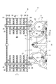
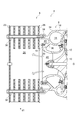
- FIG. 2 is a schematic cross-sectional view showing the overall configuration of the compression device 4.
- the centrifugal compressor 6 includes an impeller 10 for compressing air, an air guide cylinder 12 for housing the impeller 10 and guiding air, and the air that has passed through the air guide cylinder 12 outside. And a scroll casing 16 that forms a scroll chamber 14 that guides the compressor, and a compressor assembly bolt 20 that fastens the inlet side 18 of the air guide cylinder 12 and the scroll casing 16.
- the compressor assembling bolts 20 are provided at a plurality of locations at regular intervals in the circumferential direction of the impeller 10.
- the air guide tube 12 has a cylindrical shape in which the opening diameters of the inlet side 18 and the outlet side 19 are larger than the opening diameter of the intermediate portion 17.
- An impeller 10 is housed inside the air guide cylinder 12.
- the scroll casing 16 is an annular member provided on the outer peripheral side of the air guide tube 12 and is fixed to the air guide tube 12 as described later.
- An annular diffuser member 15 that forms a diffuser passage 21 that communicates the inside of the air guide tube 12 and the scroll chamber 14 is disposed on the outer peripheral side of the outlet side 19 of the air guide tube 12.
- the diffuser member 15 is fitted to the outer peripheral side of the air guide tube 12 on the outlet side 19 of the air guide tube 12 and is fastened to the scroll casing 16 by a bolt 23.
- the silencer 8 has a disk-shaped first side wall 22 extending in a direction orthogonal to the rotation axis O of the impeller 10, and a rotation axis between the first side wall 22 and the centrifugal compressor 6. And an annular second side wall 26 which is provided around O and forms an outside air introduction space 24 for guiding outside air (air) to the air guide cylinder 12 between the first side wall 22 and the second side wall 26.
- a central opening 27 is formed at the center of the second side wall 26.
- the silencer 8 passes through the entire silencer 8 along the direction of the rotation axis O of the impeller 10 and at least one silencer element 28 provided in the outside air introduction space 24 and fastens the silencer 8 and the scroll casing 16 together. And an assembly bolt.
- the silencer assembling bolt extends from the first side wall 22 to the scroll casing 16 in the direction of the rotation axis O of the impeller 10, and fastens the first side wall 22, the second side wall 26, and the scroll casing 16.
- the silencer assembling bolts 30 are provided at a plurality of locations at regular intervals in the circumferential direction of the impeller 10.
- outside air is taken into the outside air introduction space 24 from the outer peripheral side of the silencer 8.
- the flow of outside air taken into the outside air introduction space 24 passes through the silencer element 28, is then turned in the direction of the rotation axis O, passes through the central opening 27 of the annular second side wall 26, and is guided to the air guide cylinder 12. It is burned.
- the silencer assembly bolt 30 that fastens the first side wall 22 and the second side wall 26 penetrates the entire silencer 8 from the first side wall 22 along the rotation axis O direction of the impeller 10.
- the scroll casing 16 is also fastened to the scroll casing 16. Therefore, a bolt (silencer assembling bolt 30) for fastening the silencer 8 and the centrifugal compressor 6 is used as a bolt (silencer mounting bolt) for fastening the silencer 008 and the centrifugal compressor 006 in the conventional configuration (see FIG. 4). 031) can be significantly longer.
- the extension amount of the bolt can be extended without breaking.
- the bolt when a longitudinal tensile load is applied to the bolt (silencer mounting bolt 031) for fastening the silencer 008 and the centrifugal compressor 006, the bolt can be extended without breaking. Can be greater than the amount.
- the breakage of the bolt is effective. Can be suppressed. Therefore, it is possible to suppress the breakage of the bolt (silencer assembling bolt 30) for fastening the silencer 8 and the centrifugal compressor 6 and to realize a state where the silencer 8 and the centrifugal compressor 6 are stably connected.
- the silencer 8 and the centrifugal compressor 6 are fastened by using a silencer assembling bolt 30 different from the compressor assembling bolt 20 that fastens the inlet side 18 of the air guide cylinder 12 and the scroll casing 16. Therefore, even when the impeller 10 is broken and the impeller fragments collide with the air guide cylinder 12, the impact of the collision is not directly transmitted from the air guide cylinder 12 to the silencer assembly bolt 30. It is transmitted from the guide cylinder 12 to the silencer assembling bolt via the scroll casing 16. From this point of view, it is possible to effectively suppress the breakage of the silencer assembly bolt 30 that fastens the silencer 8 and the centrifugal compressor 6 as compared with the conventional configuration (see FIG. 4).
- the silencer assembling bolt 30 extends from the first side wall 22 to the scroll casing 16 in the direction of the rotation axis O of the impeller 10 and fastens the first side wall 22, the second side wall 26, and the scroll casing 16, The overall rigidity of the compression device 4 can be improved.
- At least one silencer element 28 is supported in the outside air introduction space 24 by a silencer assembly bolt 30.
- the first side wall 22, the second side wall 26, and the scroll casing 16 can be fastened using the silencer assembly bolt 30 that supports the silencer element 28 in the outside air introduction space 24. For this reason, the state which connected the silencer 8 and the centrifugal compressor 6 stably with a simple structure is realizable.
- At least one silencer element 28 includes a plurality of silencer elements 28 arranged along a radial direction around the rotation axis O.
- Each of the plurality of silencer elements 28 is an annular element provided around the rotation axis O, and has an insertion hole 32 through which the silencer assembling bolt 30 is inserted, and is inserted into the insertion hole 32. It is supported in the outside air introduction space 24 by the silencer assembling bolt 30.
- the silencer assembling bolt 30 is inserted in order through an insertion hole 42 provided in the first side wall 22, an insertion hole 32 of each silencer element 28, and an insertion hole 44 provided in the second side wall 26. It is screwed into a bolt hole 46 formed in the casing 16.
- the first side wall 22, the second side wall 2, the second side wall 22, the second side wall 22, the second side wall 22, the second side wall 22, the second side wall 22, the second side wall 22, the second side wall 22, the second side wall 22, the second side wall 22, The side wall 26 and the scroll casing 16 can be fastened. For this reason, the state which connected the silencer 8 and the centrifugal compressor 6 stably with a simple structure is realizable.
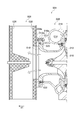
- the scroll casing 16 includes a scroll chamber forming portion 34 that forms the scroll chamber 14, and an annular first protrusion 36 that protrudes from the scroll chamber forming portion 34 toward the silencer 8. And an annular second protrusion 38 that is located on the outer side in the radial direction of the impeller 10 relative to the first protrusion 36 and protrudes from the scroll chamber forming part 34 toward the silencer 8.
- the compressor assembly bolt 20 fastens the inlet side 18 of the air guide cylinder 12 and the first protrusion 36
- the silencer assembly bolt 30 includes the first side wall 22, the second side wall 26, and the second protrusion. 38 is fastened.
- the second protrusion 38 that is fastened to the silencer 8 is located on the outer side in the radial direction of the impeller 10 rather than the first protrusion 36 that is fastened to the inlet side 18 of the air guide cylinder 12. Therefore, when the impeller 10 is broken, it is possible to reduce a risk that the impeller fragments penetrate the air guide tube 12 or the first protrusion 36 and reach the second protrusion 38 or the vicinity thereof. Thereby, the damage of the 2nd protrusion part 38 is suppressed, and the state which connected the silencer 8 and the centrifugal compressor 6 stably can be implement
- the second protrusion 38 protrudes closer to the silencer 8 than the first protrusion 36 and abuts against the second side wall 26 of the silencer 8. Further, the inlet side 18 of the air guide cylinder 12 and the silencer are arranged so that the annular space 40 formed between the first protrusion 36 and the second protrusion 38 communicates with the space 48 inside the air guide cylinder 12. A gap g is provided between the second side wall 26 and the eighth side wall 26.
- the air flowing backward from the scroll chamber 14 side to the silencer 8 has a pressure higher than the atmospheric pressure.
- the annular space 40 between the first protrusion 36 and the second protrusion 38 is formed inside the silencer 8. It becomes possible to function as a buffer space for suppressing an increase in pressure in the outside air introduction space 24.
- the present invention is not limited to the above-described embodiments, and includes forms obtained by modifying the above-described embodiments and forms obtained by appropriately combining these forms.
- the present invention is not limited to the above-described exhaust turbine supercharger (turbocharger), but is a mechanical supercharger (supercharger) that drives a compressor with power extracted from an output shaft of an internal combustion engine via a belt or the like. (Charger).
Landscapes
- Engineering & Computer Science (AREA)
- Mechanical Engineering (AREA)
- General Engineering & Computer Science (AREA)
- Chemical & Material Sciences (AREA)
- Combustion & Propulsion (AREA)
- Structures Of Non-Positive Displacement Pumps (AREA)
- Supercharger (AREA)
Priority Applications (4)
| Application Number | Priority Date | Filing Date | Title |
|---|---|---|---|
| EP17773621.2A EP3324053B1 (en) | 2016-03-30 | 2017-01-31 | Compression device and supercharger |
| KR1020187002165A KR101886607B1 (ko) | 2016-03-30 | 2017-01-31 | 압축 장치 및 과급기 |
| US15/748,386 US11359647B2 (en) | 2016-03-30 | 2017-01-31 | Compression device and supercharger |
| CN201780002512.3A CN107850090B (zh) | 2016-03-30 | 2017-01-31 | 压缩装置和增压器 |
Applications Claiming Priority (2)
| Application Number | Priority Date | Filing Date | Title |
|---|---|---|---|
| JP2016068375A JP6240251B2 (ja) | 2016-03-30 | 2016-03-30 | 圧縮装置及び過給機 |
| JP2016-068375 | 2016-03-30 |
Publications (1)
| Publication Number | Publication Date |
|---|---|
| WO2017169072A1 true WO2017169072A1 (ja) | 2017-10-05 |
Family
ID=59963777
Family Applications (1)
| Application Number | Title | Priority Date | Filing Date |
|---|---|---|---|
| PCT/JP2017/003331 Ceased WO2017169072A1 (ja) | 2016-03-30 | 2017-01-31 | 圧縮装置及び過給機 |
Country Status (6)
| Country | Link |
|---|---|
| US (1) | US11359647B2 (enExample) |
| EP (1) | EP3324053B1 (enExample) |
| JP (1) | JP6240251B2 (enExample) |
| KR (1) | KR101886607B1 (enExample) |
| CN (1) | CN107850090B (enExample) |
| WO (1) | WO2017169072A1 (enExample) |
Families Citing this family (7)
| Publication number | Priority date | Publication date | Assignee | Title |
|---|---|---|---|---|
| DE102017127628A1 (de) * | 2017-11-22 | 2019-05-23 | Man Energy Solutions Se | Turbine und Turbolader |
| DE102018100465A1 (de) * | 2018-01-10 | 2019-07-11 | Abb Turbo Systems Ag | Filterschalldämpfer für einen Abgasturbolader einer Brennkraftmaschine |
| US11067098B2 (en) | 2018-02-02 | 2021-07-20 | Carrier Corporation | Silencer for a centrifugal compressor assembly |
| EP3904697A1 (de) * | 2020-04-29 | 2021-11-03 | ABB Schweiz AG | Schalldämpfer für einen abgasturbolader einer brennkraftmaschine |
| JP7562357B2 (ja) * | 2020-09-30 | 2024-10-07 | 三菱重工マリンマシナリ株式会社 | 回転機械 |
| US11719129B2 (en) * | 2021-11-11 | 2023-08-08 | Progress Rail Locomotive Inc. | Compressor housing |
| CN115388037B (zh) * | 2022-08-02 | 2023-07-21 | 哈尔滨工程大学 | 一种具有宽频降噪效果的增压器进气整流结构 |
Citations (3)
| Publication number | Priority date | Publication date | Assignee | Title |
|---|---|---|---|---|
| JPS487681Y1 (enExample) * | 1970-08-29 | 1973-02-28 | ||
| JP2003519329A (ja) * | 2000-01-07 | 2003-06-17 | アーベーベー ターボ システムズ アクチエンゲゼルシャフト | 排ガスターボチャージャのコンプレッサのための消音器 |
| WO2015098175A1 (ja) * | 2013-12-27 | 2015-07-02 | 三菱重工業株式会社 | コンプレッサ |
Family Cites Families (10)
| Publication number | Priority date | Publication date | Assignee | Title |
|---|---|---|---|---|
| CH594139A5 (enExample) * | 1975-12-11 | 1977-12-30 | Bbc Brown Boveri & Cie | |
| DE8505239U1 (de) * | 1985-02-23 | 1987-08-20 | M.A.N.- B & W Diesel GmbH, 8900 Augsburg | Schalldämpfer mit Vorleitschaufeln an der Ansaugseite des Verdichters eines Abgasturboladers |
| JP3586559B2 (ja) * | 1998-04-03 | 2004-11-10 | 三菱重工業株式会社 | サイレンサの取付構造 |
| JP4359798B2 (ja) * | 1999-11-05 | 2009-11-04 | 株式会社Ihi | 排気タービン過給機 |
| JP4185857B2 (ja) | 2003-12-15 | 2008-11-26 | 株式会社神戸製鋼所 | サイレンサー |
| JP2005214048A (ja) * | 2004-01-28 | 2005-08-11 | Ishikawajima Harima Heavy Ind Co Ltd | 過給機用吸入消音器 |
| DE102004027594B4 (de) | 2004-06-05 | 2006-06-29 | Man B & W Diesel Ag | Strömungsmaschine mit radial durchströmtem Verdichterrad |
| CN101573516B (zh) * | 2007-02-09 | 2011-06-15 | 三菱重工业株式会社 | 排气涡轮增压器 |
| JP6391970B2 (ja) | 2014-03-31 | 2018-09-19 | 三菱重工業株式会社 | 遠心圧縮機、過給機、および遠心圧縮機の製造方法、並びにサイレンサ |
| WO2015151844A1 (ja) * | 2014-03-31 | 2015-10-08 | 三菱重工業株式会社 | 遠心圧縮機、過給機、および遠心圧縮機の製造方法 |
-
2016
- 2016-03-30 JP JP2016068375A patent/JP6240251B2/ja active Active
-
2017
- 2017-01-31 WO PCT/JP2017/003331 patent/WO2017169072A1/ja not_active Ceased
- 2017-01-31 KR KR1020187002165A patent/KR101886607B1/ko active Active
- 2017-01-31 US US15/748,386 patent/US11359647B2/en active Active
- 2017-01-31 EP EP17773621.2A patent/EP3324053B1/en active Active
- 2017-01-31 CN CN201780002512.3A patent/CN107850090B/zh active Active
Patent Citations (3)
| Publication number | Priority date | Publication date | Assignee | Title |
|---|---|---|---|---|
| JPS487681Y1 (enExample) * | 1970-08-29 | 1973-02-28 | ||
| JP2003519329A (ja) * | 2000-01-07 | 2003-06-17 | アーベーベー ターボ システムズ アクチエンゲゼルシャフト | 排ガスターボチャージャのコンプレッサのための消音器 |
| WO2015098175A1 (ja) * | 2013-12-27 | 2015-07-02 | 三菱重工業株式会社 | コンプレッサ |
Non-Patent Citations (1)
| Title |
|---|
| See also references of EP3324053A4 * |
Also Published As
| Publication number | Publication date |
|---|---|
| EP3324053A4 (en) | 2018-09-19 |
| CN107850090A (zh) | 2018-03-27 |
| CN107850090B (zh) | 2019-03-15 |
| US11359647B2 (en) | 2022-06-14 |
| KR20180016607A (ko) | 2018-02-14 |
| KR101886607B1 (ko) | 2018-08-07 |
| JP6240251B2 (ja) | 2017-11-29 |
| JP2017180283A (ja) | 2017-10-05 |
| EP3324053B1 (en) | 2020-03-11 |
| EP3324053A1 (en) | 2018-05-23 |
| US20180223871A1 (en) | 2018-08-09 |
Similar Documents
| Publication | Publication Date | Title |
|---|---|---|
| JP6240251B2 (ja) | 圧縮装置及び過給機 | |
| CN100470041C (zh) | 在前端具有两个风扇的涡轮喷气发动机结构 | |
| CN105715308B (zh) | 用于防涡轮增压器爆裂的压缩机组件 | |
| CN102066717A (zh) | 涡轮增压机用的压缩机壳体 | |
| JPWO2015146765A1 (ja) | インペラ締結構造及びターボ圧縮機 | |
| JP2017180283A5 (enExample) | ||
| CN107208544B (zh) | 增压器 | |
| JP6379568B2 (ja) | スクロール及びターボ圧縮機 | |
| WO2016193002A1 (en) | A centrifugal refrigeration compressor | |
| WO2016002031A1 (ja) | コンプレッサ | |
| JPH1047011A (ja) | 排ガスターボ過給機の軸流タービン | |
| US20210095691A1 (en) | Centrifugal compressor | |
| EP3073091B1 (en) | Compressor | |
| JP5230590B2 (ja) | 排気タービン過給機の排気入口ケーシング | |
| JP6133439B2 (ja) | 圧縮機および過給機 | |
| JP6097188B2 (ja) | 過給機 | |
| CN103477050B (zh) | 涡轮增压机 | |
| EP3009634B1 (en) | Compressor and turbocharger | |
| US20140271173A1 (en) | Centrifugal compressor with axial impeller exit | |
| WO2015151844A1 (ja) | 遠心圧縮機、過給機、および遠心圧縮機の製造方法 | |
| KR20200116736A (ko) | 로터디스크 댐퍼 및 이를 포함하는 가스 터빈 | |
| JP2009103087A (ja) | ガスタービン、及びガスタービン用ロータ | |
| JP6541956B2 (ja) | 遠心圧縮機およびそれを備えた過給機 | |
| JPWO2017090073A1 (ja) | 静止部材の固定ボルト、及び、遠心圧縮機 |
Legal Events
| Date | Code | Title | Description |
|---|---|---|---|
| ENP | Entry into the national phase |
Ref document number: 20187002165 Country of ref document: KR Kind code of ref document: A |
|
| WWE | Wipo information: entry into national phase |
Ref document number: 15748386 Country of ref document: US |
|
| NENP | Non-entry into the national phase |
Ref country code: DE |