WO2017168975A1 - 流量制御装置 - Google Patents
流量制御装置 Download PDFInfo
- Publication number
- WO2017168975A1 WO2017168975A1 PCT/JP2017/001633 JP2017001633W WO2017168975A1 WO 2017168975 A1 WO2017168975 A1 WO 2017168975A1 JP 2017001633 W JP2017001633 W JP 2017001633W WO 2017168975 A1 WO2017168975 A1 WO 2017168975A1
- Authority
- WO
- WIPO (PCT)
- Prior art keywords
- press
- control device
- welding
- fuel
- abutting
- Prior art date
- Legal status (The legal status is an assumption and is not a legal conclusion. Google has not performed a legal analysis and makes no representation as to the accuracy of the status listed.)
- Ceased
Links
Images


Classifications
-
- F—MECHANICAL ENGINEERING; LIGHTING; HEATING; WEAPONS; BLASTING
- F02—COMBUSTION ENGINES; HOT-GAS OR COMBUSTION-PRODUCT ENGINE PLANTS
- F02M—SUPPLYING COMBUSTION ENGINES IN GENERAL WITH COMBUSTIBLE MIXTURES OR CONSTITUENTS THEREOF
- F02M51/00—Fuel-injection apparatus characterised by being operated electrically
- F02M51/06—Injectors peculiar thereto with means directly operating the valve needle
- F02M51/061—Injectors peculiar thereto with means directly operating the valve needle using electromagnetic operating means
- F02M51/0625—Injectors peculiar thereto with means directly operating the valve needle using electromagnetic operating means characterised by arrangement of mobile armatures
- F02M51/0664—Injectors peculiar thereto with means directly operating the valve needle using electromagnetic operating means characterised by arrangement of mobile armatures having a cylindrically or partly cylindrically shaped armature, e.g. entering the winding; having a plate-shaped or undulated armature entering the winding
- F02M51/0685—Injectors peculiar thereto with means directly operating the valve needle using electromagnetic operating means characterised by arrangement of mobile armatures having a cylindrically or partly cylindrically shaped armature, e.g. entering the winding; having a plate-shaped or undulated armature entering the winding the armature and the valve being allowed to move relatively to each other or not being attached to each other
-
- F—MECHANICAL ENGINEERING; LIGHTING; HEATING; WEAPONS; BLASTING
- F02—COMBUSTION ENGINES; HOT-GAS OR COMBUSTION-PRODUCT ENGINE PLANTS
- F02M—SUPPLYING COMBUSTION ENGINES IN GENERAL WITH COMBUSTIBLE MIXTURES OR CONSTITUENTS THEREOF
- F02M51/00—Fuel-injection apparatus characterised by being operated electrically
- F02M51/06—Injectors peculiar thereto with means directly operating the valve needle
- F02M51/061—Injectors peculiar thereto with means directly operating the valve needle using electromagnetic operating means
- F02M51/0625—Injectors peculiar thereto with means directly operating the valve needle using electromagnetic operating means characterised by arrangement of mobile armatures
- F02M51/0635—Injectors peculiar thereto with means directly operating the valve needle using electromagnetic operating means characterised by arrangement of mobile armatures having a plate-shaped or undulated armature not entering the winding
- F02M51/0642—Injectors peculiar thereto with means directly operating the valve needle using electromagnetic operating means characterised by arrangement of mobile armatures having a plate-shaped or undulated armature not entering the winding the armature having a valve attached thereto
- F02M51/0653—Injectors peculiar thereto with means directly operating the valve needle using electromagnetic operating means characterised by arrangement of mobile armatures having a plate-shaped or undulated armature not entering the winding the armature having a valve attached thereto the valve being an elongated body, e.g. a needle valve
-
- F—MECHANICAL ENGINEERING; LIGHTING; HEATING; WEAPONS; BLASTING
- F02—COMBUSTION ENGINES; HOT-GAS OR COMBUSTION-PRODUCT ENGINE PLANTS
- F02M—SUPPLYING COMBUSTION ENGINES IN GENERAL WITH COMBUSTIBLE MIXTURES OR CONSTITUENTS THEREOF
- F02M51/00—Fuel-injection apparatus characterised by being operated electrically
- F02M51/06—Injectors peculiar thereto with means directly operating the valve needle
- F02M51/0603—Injectors peculiar thereto with means directly operating the valve needle using piezoelectric or magnetostrictive operating means
- F02M51/0607—Injectors peculiar thereto with means directly operating the valve needle using piezoelectric or magnetostrictive operating means the actuator being hollow, e.g. with needle passing through the hollow space
-
- F—MECHANICAL ENGINEERING; LIGHTING; HEATING; WEAPONS; BLASTING
- F02—COMBUSTION ENGINES; HOT-GAS OR COMBUSTION-PRODUCT ENGINE PLANTS
- F02M—SUPPLYING COMBUSTION ENGINES IN GENERAL WITH COMBUSTIBLE MIXTURES OR CONSTITUENTS THEREOF
- F02M51/00—Fuel-injection apparatus characterised by being operated electrically
- F02M51/06—Injectors peculiar thereto with means directly operating the valve needle
- F02M51/061—Injectors peculiar thereto with means directly operating the valve needle using electromagnetic operating means
- F02M51/0625—Injectors peculiar thereto with means directly operating the valve needle using electromagnetic operating means characterised by arrangement of mobile armatures
- F02M51/0664—Injectors peculiar thereto with means directly operating the valve needle using electromagnetic operating means characterised by arrangement of mobile armatures having a cylindrically or partly cylindrically shaped armature, e.g. entering the winding; having a plate-shaped or undulated armature entering the winding
- F02M51/0671—Injectors peculiar thereto with means directly operating the valve needle using electromagnetic operating means characterised by arrangement of mobile armatures having a cylindrically or partly cylindrically shaped armature, e.g. entering the winding; having a plate-shaped or undulated armature entering the winding the armature having an elongated valve body attached thereto
- F02M51/0675—Injectors peculiar thereto with means directly operating the valve needle using electromagnetic operating means characterised by arrangement of mobile armatures having a cylindrically or partly cylindrically shaped armature, e.g. entering the winding; having a plate-shaped or undulated armature entering the winding the armature having an elongated valve body attached thereto the valve body having cylindrical guiding or metering portions, e.g. with fuel passages
-
- F—MECHANICAL ENGINEERING; LIGHTING; HEATING; WEAPONS; BLASTING
- F02—COMBUSTION ENGINES; HOT-GAS OR COMBUSTION-PRODUCT ENGINE PLANTS
- F02M—SUPPLYING COMBUSTION ENGINES IN GENERAL WITH COMBUSTIBLE MIXTURES OR CONSTITUENTS THEREOF
- F02M61/00—Fuel-injectors not provided for in groups F02M39/00 - F02M57/00 or F02M67/00
- F02M61/16—Details not provided for in, or of interest apart from, the apparatus of groups F02M61/02 - F02M61/14
- F02M61/168—Assembling; Disassembling; Manufacturing; Adjusting
-
- F—MECHANICAL ENGINEERING; LIGHTING; HEATING; WEAPONS; BLASTING
- F02—COMBUSTION ENGINES; HOT-GAS OR COMBUSTION-PRODUCT ENGINE PLANTS
- F02M—SUPPLYING COMBUSTION ENGINES IN GENERAL WITH COMBUSTIBLE MIXTURES OR CONSTITUENTS THEREOF
- F02M63/00—Other fuel-injection apparatus having pertinent characteristics not provided for in groups F02M39/00 - F02M57/00 or F02M67/00; Details, component parts, or accessories of fuel-injection apparatus, not provided for in, or of interest apart from, the apparatus of groups F02M39/00 - F02M61/00 or F02M67/00; Combination of fuel pump with other devices, e.g. lubricating oil pump
- F02M63/0012—Valves
- F02M63/0014—Valves characterised by the valve actuating means
- F02M63/0015—Valves characterised by the valve actuating means electrical, e.g. using solenoid
- F02M63/0017—Valves characterised by the valve actuating means electrical, e.g. using solenoid using electromagnetic operating means
-
- F—MECHANICAL ENGINEERING; LIGHTING; HEATING; WEAPONS; BLASTING
- F02—COMBUSTION ENGINES; HOT-GAS OR COMBUSTION-PRODUCT ENGINE PLANTS
- F02M—SUPPLYING COMBUSTION ENGINES IN GENERAL WITH COMBUSTIBLE MIXTURES OR CONSTITUENTS THEREOF
- F02M2200/00—Details of fuel-injection apparatus, not otherwise provided for
- F02M2200/80—Fuel injection apparatus manufacture, repair or assembly
- F02M2200/8061—Fuel injection apparatus manufacture, repair or assembly involving press-fit, i.e. interference or friction fit
-
- F—MECHANICAL ENGINEERING; LIGHTING; HEATING; WEAPONS; BLASTING
- F02—COMBUSTION ENGINES; HOT-GAS OR COMBUSTION-PRODUCT ENGINE PLANTS
- F02M—SUPPLYING COMBUSTION ENGINES IN GENERAL WITH COMBUSTIBLE MIXTURES OR CONSTITUENTS THEREOF
- F02M2200/00—Details of fuel-injection apparatus, not otherwise provided for
- F02M2200/80—Fuel injection apparatus manufacture, repair or assembly
- F02M2200/8084—Fuel injection apparatus manufacture, repair or assembly involving welding or soldering
-
- F—MECHANICAL ENGINEERING; LIGHTING; HEATING; WEAPONS; BLASTING
- F02—COMBUSTION ENGINES; HOT-GAS OR COMBUSTION-PRODUCT ENGINE PLANTS
- F02M—SUPPLYING COMBUSTION ENGINES IN GENERAL WITH COMBUSTIBLE MIXTURES OR CONSTITUENTS THEREOF
- F02M51/00—Fuel-injection apparatus characterised by being operated electrically
- F02M51/06—Injectors peculiar thereto with means directly operating the valve needle
- F02M51/061—Injectors peculiar thereto with means directly operating the valve needle using electromagnetic operating means
- F02M51/0625—Injectors peculiar thereto with means directly operating the valve needle using electromagnetic operating means characterised by arrangement of mobile armatures
- F02M51/0628—Injectors peculiar thereto with means directly operating the valve needle using electromagnetic operating means characterised by arrangement of mobile armatures having a stepped armature
-
- F—MECHANICAL ENGINEERING; LIGHTING; HEATING; WEAPONS; BLASTING
- F02—COMBUSTION ENGINES; HOT-GAS OR COMBUSTION-PRODUCT ENGINE PLANTS
- F02M—SUPPLYING COMBUSTION ENGINES IN GENERAL WITH COMBUSTIBLE MIXTURES OR CONSTITUENTS THEREOF
- F02M61/00—Fuel-injectors not provided for in groups F02M39/00 - F02M57/00 or F02M67/00
- F02M61/16—Details not provided for in, or of interest apart from, the apparatus of groups F02M61/02 - F02M61/14
- F02M61/18—Injection nozzles, e.g. having valve seats; Details of valve member seated ends, not otherwise provided for
- F02M61/1873—Valve seats or member ends having circumferential grooves or ridges, e.g. toroidal
Definitions
- the present invention relates to a flow rate control device.
- a movable valve is formed of an electromagnetic core and a movable needle portion having different material compositions, and the movable valve formed by welding and joining the two members is movable with an end surface portion of the electromagnetic core.
- the welded portion has a welded joint structure in which the butted portion is welded to the needle portion, the movable needle portion has a flange portion, and the butted surfaces of the flange portion and the end surface portion of the electromagnetic core are locally melted and solidified. Is disclosed as a melting portion larger than the length of the abutting surface. (For example, see FIG.
- Patent Document 1 By butting at least part of the movable needle part and the electromagnetic core, and irradiating the butt part with YAG laser light and welding a distance longer than the butt surface, a fuel injection valve having excellent durability can be mass-produced and provided.
- the maximum fuel pressure for regular use may increase to about 35 MP.
- the fuel injection valve is required to hold the fuel up to 55 MPa, for example.
- An object of the present invention is to reduce the manufacturing cost of a fuel injection device capable of ensuring a weld strength sufficient to withstand a high fuel pressure and to provide it at a low cost.
- the present invention provides a flow rate control device comprising a first component and a second component having a facing surface facing the one surface of the first component, the one surface of the first component, A welded portion formed so as to be along the abutting surface at the abutting surface that contacts each other between the facing surface of the second component and the abutting surface of the first component and the second component A gap is formed between the welded part, the first part, and the second part, and a welding direction tip of the welding part is welded to a welding direction tip of the abutting surface. It is located on the side.
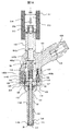
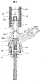
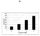
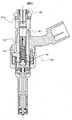
- FIG. 1 is a partial cross-sectional view of a fuel injection device and a fuel pipe according to an embodiment of the present invention. It is another sectional drawing of a part of fuel injection apparatus and fuel piping by embodiment of this invention. It is the graph which showed the relationship between the fuel pressure inside a fuel injection valve, and the load applied to a fuel injection valve axial direction. It is a whole sectional view of a fuel injection device by a comparative example. It is an expanded sectional view of the welding part of the fuel injection device by a comparative example. It is sectional drawing of the component of the fuel-injection apparatus by the Example of this invention. It is an expanded sectional view of the welding part of the fuel-injection apparatus by the Example of this invention.
- a fuel injection valve fuel injection device
- the present invention is not limited to this.
- a fuel injection valve fuel injection device
- the present invention is not limited to this.
- the size of the parts and the size of the gap may be exaggerated from the actual ratio to make the function easy to understand, and unnecessary parts may be omitted to explain the function. is there.
- the same reference numerals are given to the same constituent elements, and redundant description is omitted.
- FIGS. 1A and 1B are longitudinal sectional views of a fuel injection valve according to this embodiment.
- the internal combustion engine is provided with a fuel injection control device (not shown) that performs an operation of converting an appropriate fuel amount corresponding to an operating state into an injection time of the fuel injection valve and drives a fuel injection valve that supplies fuel. Yes.
- the movable part 114 includes a cylindrical movable element 102 and a needle valve 114A (valve element) located at the center of the movable element 102.
- a gap is provided between the end surface of the fixed core 107 (stator) having a fuel introduction hole for introducing fuel to the center and the end surface of the mover 102.
- An electromagnetic coil 105 (solenoid) for supplying magnetic flux to the magnetic path including the gap is provided.
- the fixed core 107 (stator) is arranged to face the mover 102 as shown in FIG. 1A.
- the mover 102 is driven by the magnetic attraction generated between the end face of the mover 102 and the end face of the fixed core 107 by the magnetic flux passing through the gap to drive the mover 102, and the needle valve 114A is
- the fuel passage provided in the valve seat portion 39 is opened by being separated from the seat portion 39 (valve seat). In other words, the mover 102 drives the needle valve 114A (valve element).
- the amount of fuel to be injected is mainly determined by the pressure difference between the fuel pressure and the atmospheric pressure at the injection port of the fuel injection valve, and the time during which the fuel is injected while maintaining the needle valve 114A open. .
- the magnetic attractive force acting on the mover 102 disappears, the force of the elastic member that urges the needle valve 114A in the closing direction, and the fuel flowing between the needle valve 114A and the fixed core 107.
- the needle valve 114A and the mover 102 move in the closing direction due to a pressure drop caused by the flow velocity of the valve, and the needle valve 114A is seated on the valve seat portion 39 to close the fuel passage.
- the fuel is sealed by the contact between the needle valve 114A and the valve seat portion 39, and the fuel is prevented from leaking from the fuel injection valve at an unintended timing.
- the fuel injection pressure is reduced from the conventional 20 MPa to about 35 MPa, for example. Attempts have been made to reduce the droplet diameter of the injected fuel and promote vaporization.
- the needle valve 114A and the spring are provided inside the fuel injection valve while reducing the axial load by reducing the diameter of the fuel passage at the connection portion with the fuel pipe 211. 110, it is difficult to increase the wall thickness because it is necessary to secure an inner diameter in which the adjuster 54 can be accommodated. In order to maintain a margin for strength even at high stress, it is effective to select a material with high yield stress and tensile strength.
- the fixed core 107 of the fuel injection valve constitutes a part of an electromagnetic solenoid
- a material having excellent magnetic characteristics is used. Since materials having excellent magnetic properties generally have low yield stress and tensile strength, they are unsuitable for use in the connecting portion with the fuel pipe 211 where the wall thickness is small and high rigidity is required as described above. Therefore, the fuel injection valve corresponding to the high fuel pressure is divided into two parts, the fixed core 107 and the adapter 140.
- the adapter 140 is made of a material having higher yield stress and tensile strength than the fixed core 107. In some cases, a material having excellent magnetic properties is used, two parts are press-fitted in the radial direction, and then welded all around at 403a to be fixed.
- the fuel injection valve that does not deteriorate the magnetic characteristics of the fixed core 107 while reducing the axial load by reducing the diameter of the fuel passage with the fuel pipe 211 and the cost increases. It is possible to manufacture with reduced.
- the nozzle holder 23 is made of a material having higher yield stress and tensile strength than the fixed core 107, and the fixed core 107 has excellent magnetic properties. In some cases, the material is used and two parts are press-fitted in the radial direction, and then welded around 403b and fixed.
- FIG. 1A schematically shows the load applied in the axial direction of the fuel injection valve by the fuel pressure. Since the fuel injection valve is connected to the fuel pipe 211 and the fuel is sealed by the O-ring 212, the fuel pipe interior 213 and the fuel injection valve are filled with high-pressure fuel.
- the fuel pipe sectional area is determined by the fuel pipe inner diameter ⁇ R, and the product of the fuel pipe sectional area and the fuel pressure is defined as a fuel pressure load.
- the fuel injection valve receives a fuel pressure load in the direction of the arrow 214.
- the fuel injection valve is in contact with the engine (not shown) through the tapered surface 215 of the housing 103, so that the above-described fuel injection valve is connected via the adapter 140, the fixed core 107, the injection hole cup support 101 and the housing 103.
- the fuel pressure load is transmitted.
- FIG. 2 is a graph in which the load in the axial direction of the fuel injector is calculated with respect to the fuel pressure applied inside the fuel injector.
- the maximum fuel pressure is used at, for example, 20 MPa, and the load applied in the axial direction of the fuel injection valve by the fuel pressure at that time is, for example, 1800 N.
- the fuel pressure load is approximately 1.5 times 3200 N.
- the nozzle hole cup support 101 includes a small-diameter cylindrical portion 22 having a small diameter and a large-diameter cylindrical portion 23 having a large diameter.
- An injection hole cup 116 fuel injection hole forming member
- the guide part 115 has a function of guiding the outer periphery when the valve body tip part 114B provided at the tip of the needle valve 114A constituting the movable part 114 moves up and down in the axial direction of the fuel injection valve.
- a conical valve seat portion 39 is formed on the downstream side of the guide portion 115.
- a valve body tip 114B provided at the tip of the needle valve 114A abuts on or separates from the valve seat sheet 39, thereby blocking the flow of fuel or guiding it to the fuel injection hole.
- a groove is formed on the outer periphery of the nozzle hole cup support 101, and a combustion gas seal member typified by a resin-made chip seal 131 is fitted into the groove.
- a needle valve guide portion 113 (needle valve guide member) that guides a needle valve 114 ⁇ / b> A that constitutes a mover is provided at the inner peripheral lower end portion of the fixed core 107.
- the needle valve 114A is provided with a guide portion 127, although not shown guide portion 127 forms a fuel passage provided some chamfer.
- the elongated needle valve 114A has a radial position defined by the needle valve guide 113 and is guided to reciprocate straight in the axial direction. Note that the valve opening direction is an upward direction of the valve shaft, and the valve closing direction is a downward direction of the valve shaft direction.
- a head 114C having a stepped portion 129 having an outer diameter larger than the diameter of the needle valve 114A is provided at the end opposite to the end where the valve body tip 114B of the needle valve 114A is provided.
- the upper surface of the stepped portion 129 is provided with a seating surface for the spring 110 that urges the needle valve 114A in the valve closing direction, and holds the spring 110 together with the head portion 114C.
- the mover portion 114 has a mover 102 provided with a through hole 128 through which the needle valve 114A passes.
- a zero spring 112 that biases the movable element 102 in the valve opening direction is held between the movable element 102 and the needle valve guide portion 113.
- the diameter of the through hole 128 is smaller than the diameter of the stepped portion 129 of the head portion 114C, under the biasing force of the spring 110 or the action of gravity that presses the needle valve 114A toward the valve seat of the nozzle hole cup 116.
- the upper surface of the movable element 102 held by the zero spring 112 is in contact with the lower end surface of the stepped portion 129 of the needle valve 114A, and both are engaged.
- the two cooperate in response to the upward movement of the mover 102 against the urging force or gravity of the zero spring 112 or the downward movement of the needle valve 114A along the urging force of the zero spring 112 or gravity. It will move.
- the force for moving the needle valve 114A upward or the force for moving the mover 102 downward acts independently of each other regardless of the biasing force or gravity of the zero spring 112, they may move in different directions. it can.
- the fixed core 107 is press-fitted into the inner peripheral portion of the large-diameter cylindrical portion 23 of the nozzle hole cup support 101 and is welded and joined at the press-fit contact position. A gap formed between the inside of the large-diameter cylindrical portion 23 of the nozzle hole cup support 101 and the outside air is sealed by this welding joint.
- a through hole 107D having a diameter ⁇ Cn is provided as a fuel introduction passage.
- the adapter 140 and the fixed core are press-fitted by direct contact between the lower surface (downstream surface) of the adapter 140 (pipe) and the upper surface (upstream surface) of the fixed core 107 (stator). 107 is fixed.
- the lower end surface of the fixed core 107, the upper end surface of the movable element 102, and the collision end surface are plated to improve durability. Even when relatively soft soft magnetic stainless steel is used for the mover 102, durability reliability can be ensured by using hard chromium plating or electroless nickel plating.
- the lower end of the initial load setting spring 110 is in contact with the spring receiving surface formed on the upper end surface of the stepped portion 129 provided on the head portion 114C of the needle valve 114A, and the other end of the spring 110 is the adjuster. Received at 54. As a result, the spring 110 is held between the head 114 ⁇ / b> C and the adjuster 54. By adjusting the fixing position of the adjuster 54, the initial load by which the spring 110 presses the needle valve 114A against the valve seat portion 39 can be adjusted.
- a cup-shaped housing 103 is fixed to the outer periphery of the large-diameter cylindrical portion 23 of the nozzle hole cup support 101.
- a through hole is provided at the center of the bottom of the housing 103, and the large-diameter cylindrical portion 23 of the nozzle hole cup support 101 is inserted through the through hole.
- a portion of the outer peripheral wall of the housing 103 forms an outer peripheral yoke portion facing the outer peripheral surface of the large-diameter cylindrical portion 23 of the nozzle hole cup support 101.
- An electromagnetic coil 105 wound in an annular shape is disposed in a cylindrical space formed by the housing 103.
- the electromagnetic coil 105 is formed by an annular coil bobbin 104 having a U-shaped groove that opens outward in the radial direction, and a copper wire wound in the groove.
- a rigid conductor 109 is fixed at the start and end of winding of the electromagnetic coil 105 and is drawn out from a through hole provided in the fixed core 107.
- the conductor 109, the fixed core 107, and the outer periphery of the large-diameter cylindrical portion 23 of the nozzle hole cup support 101 are molded by injecting insulating resin from the inner periphery of the upper end opening of the housing 103 and covered with the resin molded body 121. Is called. Thus, a toroidal magnetic path is formed around the electromagnetic coils (104, 105).
- a plug for supplying power from a high-voltage power source and a battery power source is connected to the connector 43A formed at the tip of the conductor 109, and energization and de-energization are controlled by a controller (not shown).
- a controller not shown.
- set the magnetic attraction force is generated, the movable element 102 of the spring 110 between the anchor 102 of the movable member 114 in the magnetic attraction gap by the magnetic flux passing through the magnetic circuit 140M and the fixed core 107 It moves upward by being sucked with a force exceeding the load.
- the mover 102 engages with the needle valve head 114C, moves upward together with the needle valve 114A, and moves until the upper end surface of the mover 102 collides with the lower end surface of the fixed core 107.
- the valve body front end portion 114B at the front end of the needle valve 114A is separated from the valve seat portion 39, and the fuel passes through the fuel passage and is ejected from the fuel injection hole 117 at the front end of the injection hole cup 116 into the combustion chamber of the internal combustion engine. To do.
- the elongate needle valve 114A While the valve body front end portion 114B at the front end of the needle valve 114A is separated from the valve seat portion 39 and pulled upward, the elongate needle valve 114A has a needle valve guide portion 113 and a guide portion for the injection hole cup 116. It is guided by the two portions 115 so as to return straight along the valve shaft direction.
- valve body tip 114B at the tip of the needle valve 114A contacts the valve seat portion 39 and is in the valve closing position, the elongated needle valve 114A is guided only by the needle valve guide 113, and the injection hole cup 116 It is not in contact with the guide part 115.
- the stepped portion 129 of the head portion 114C comes into contact with the upper surface of the movable element 102 and moves the movable element 102 to the needle valve guide section 113 side by overcoming the force of the zero spring 112.
- the mover 102 is separate from the needle valve 114A, and therefore continues to move in the direction of the needle valve guide portion 113 due to inertial force.
- friction due to fluid is generated between the outer periphery of the needle valve 114A and the inner periphery of the mover 102, and the energy of the needle valve 114A that rebounds from the valve seat sheet portion 39 in the valve opening direction again is absorbed.
- the movable element 102 having a large inertial mass is separated from the needle valve 114A, the rebound energy itself is reduced. Further, since the inertial force of the movable element 102 that has absorbed the rebound energy of the needle valve 114A is reduced by that amount and the repulsive force received after the zero spring 112 is compressed is also reduced, the needle valve is caused by the rebound phenomenon of the movable element 102 itself. The phenomenon that 114A is moved again in the valve opening direction is less likely to occur. Thus, the rebound of the needle valve 114A is minimized, and the so-called secondary injection phenomenon in which the valve is opened after the energization of the electromagnetic coil 105 is cut off and the fuel is injected randomly is suppressed.
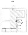
- FIG. 3A shows a cross-sectional view of a fuel injection valve according to a comparative example.
- the fixed core 407 is joined by lap welding after being press-fitted into the nozzle holder 23.
- FIG. 3B is an enlarged view of the vicinity 460 of the lap weld portion of the fuel injection valve shown in FIG.
- the nozzle holder 23 receives the load 305 in the outer diameter direction and the fuel injection valve axial direction downward due to the fuel pressure.
- the load mainly acting on the lap weld 301 is The nozzle holder 23 is directed downward in the fuel injection valve axial direction by the fuel pressure.
- the boundary surface during the lap welding of the fixed core 407 and the nozzle holder 23 is 302
- a shear load is generated on the boundary surface 302.
- a high stress is generated at the upper end 303 of the boundary surface 302 due to the shear load. This is because even if the length of the boundary surface 302 during lap welding is increased, stress is concentrated on the upper end 303 when a downward load in the fuel injection valve axial direction is applied to the nozzle holder 23.
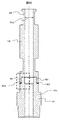
- FIG. 4A is a sectional view of only the adapter 140 and the fixed core 107 constituting the fuel injection valve according to the embodiment of the present invention. Since the thickness of the O-ring mounting portion 250 is small for the adapter 140, a material giving priority to strength is selected. Because of the selected material giving priority to strength, it can withstand the stress generated at a fuel pressure of 35 MPa. Since the fixed core 107 constitutes a magnetic circuit, there is no thin portion. Therefore, a material having excellent magnetism is selected for the fixed core 107. Since the wall thickness is large, even when a material with low strength is selected, it can withstand the stress generated at a fuel pressure of 35 MPa.
- the saturation magnetic flux density of the fixed core 107 is composed of a member separate from the fixed core 107 and is directly fixed to the fixed core 107 by press-fitting. Bigger than. Thereby, for example, the manufacturing cost of the adapter 140 can be reduced while ensuring the magnetic characteristics of the fixed core 107.
- the tensile strength of the fixed core 107 is smaller than the tensile strength of the adapter 140 (pipe) that is directly fixed to the fixed core 107 by press-fitting.
- the strength of the adapter 140 can be secured and the processing can be easily performed.
- the butt portion is composed of part A and part B, and it is necessary to hold the high-pressure fuel filled in the fuel injection valve interior 601.
- the attachment portion 401 of the adapter 140 of the fuel injection valve and the attachment portion 402 of the fixed core 107 are in radial contact with each other, press-fitted, and butt welded all around by a butt weld 403 to seal the fuel. Since the attachment portion 401 of the adapter 140 and the attachment portion 402 of the fixed core 107 are press-fitted and fixed before welding, it is possible to suppress the adapter 140 from falling due to distortion generated during welding.
- the fixed core 107 (stator) has a mounting portion 402 (stator side mounting portion) on the upstream side
- the adapter 140 (pipe) has a mounting portion 401 (pipe side mounting portion) on the downstream side.
- the attachment portion 402 and the attachment portion 401 are press-fitted in direct contact with each other in the radial direction.
- the attachment portion 402 and the attachment portion 401 can be easily manufactured, and the attachment portion 402 and the attachment portion 401 can be press-fitted and fixed.
- the downstream end 401a of the attachment portion 401 comes into contact with the upper surface (upstream surface) of the attachment portion 402 (stator side attachment portion), and butt welding is performed at this contact portion.
- the attachment portion 401 (pipe side attachment portion) is positioned on the outer peripheral side of the attachment portion 402 (stator side attachment portion), and the downstream end portion 401a of the attachment portion 401 contacts the fixed core 107 in the axial direction. Then, butt welding is performed at the contact portion.
- the fixed core 107 (stator) is formed with a protruding portion 107a (collar portion) protruding outward from the mounting portion 402 (stator side mounting portion) on the downstream side. And an integral member.
- the fixed core 107 is formed by cold forging. Thereby, even if there exists the protrusion part 107a, it becomes possible to reduce a waste of material and to manufacture cheaply.
- the projecting portion 107a (rib portion) forms a good magnetic path between the projecting portion 107a and the end portion (upper end) of the housing 103 opposite to the projecting portion 107a, thereby reliably configuring the magnetic circuit 140M (see FIG. 1A). can do.
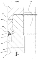
- FIG. 4B shows an enlarged cross-sectional view of the butt weld when the fuel injection adapter 140 and the fixed core 107 are butt welded.
- a shape obtained by re-solidifying the metal melted by welding is represented by 403.
- the abutment surface 609 of the adapter 140 and the fixed core 107 is perpendicular to the main load direction 510. Therefore, since the load 510 is received almost evenly by the butt surface 609, the maximum stress generated is smaller than that of the lap welding of FIG. 3B.
- the fuel injection valve according to the present embodiment attaches the fixed core 107 having the attachment portion 401 (first part) of the adapter 140 and the facing surface (upstream surface) facing one surface (downstream surface) of the first component.
- Unit 402 second component.
- an abutting surface that contacts each other is formed between one surface (downstream surface) of the first component and the opposing surface (upstream surface) of the second component, and the abutting surface is along the abutting surface.
- Butt welds 403 are formed. Further, a gap is formed by the butt weld 403, the first part, and the second part, and the welding direction tip of the butt welding part 403 is welded to the welding direction tip of the abutting surface (FIG. 4B). In the right direction side).
- a press-fit portion is formed on the upper side of the gap, in which the attachment portion 401 (first component) of the adapter 140 and the attachment portion 402 (second component) of the fixed core 107 are press-fitted in the radial direction. That is, the attachment part 401 (first part) of the adapter 140 and the attachment part 402 (second part) of the fixed core 107 are firmly fixed by the butt welding part 403 in addition to the press-fitting part. Then, according to the method shown in FIG. 3B for the welded part at that time, there is a possibility that the fixing strength is insufficient due to the concentration of stress, but the fixing strength can be improved by the method of FIG. 4B. is there.
- butt weld 403 is welded so as to have a strength that can withstand the fuel pressure load.
- Butt welding has higher joint efficiency than lap welding performed with conventional fuel injection valves, and strength is improved for the same penetration amount.
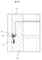
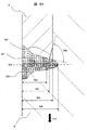
- FIG. 4C shows the butt portion and the shape of melting and re-solidification by welding further enlarged.
- the gap 605 is formed by digging the corner side of the member B as shown in the figure so that the abutting surface 609 is in close contact, or chamfering the corner of the member A (not shown).
- laser welding is performed in a shape as indicated by 606 in order to fill all the gaps 605 with molten metal.
- the reason why all the molten metal is filled is that, when a load in the direction of the arrow in the figure is applied to the two parts, the stress increases depending on the shape of the gap, and the strength of the weld may be reduced. That is, even in butt welding, the shape of the welded portion that protrudes into the abutting gap may cause stress concentration.
- the tip in the welding direction is the attachment part 401 (first part) of the adapter 140 and the attachment part 402 (second part) of the fixed core 107.
- a position is further formed on the welding direction side (right side in FIG. 4C).
- the welded portions 606, 607, and 608 are formed so as to fill all gaps formed between the first component 401 and the second component 402 before welding. As a result, the stress increases due to the shape of the gap, and the possibility of reducing the strength of the welded portion can be suppressed.
- the penetration depth 610 of welding has a variation with respect to the target aimed in the manufacturing process, and even if welding is performed aiming at the penetration shape of 606, the penetration depth is actually smaller than that. It becomes the shape 611, and there is a possibility that a gap remains after welding. Therefore, in order to fill all the gaps 605 in FIG. 4C with the molten metal, the weld shape 607 is aimed, so that the weld shape 606 is obtained even when the variation occurs and the penetration depth is reduced.
- FIG. 4D shows a welded portion shape when the penetration depth of butt welding is 614 in order to suppress the deterioration of the coaxial.
- the penetration depth is equal to or shorter than the abutting length, it is obvious that the end portion 615 of the welded portion draws stress concentration with respect to the load direction 600. Therefore, even in butt welding, if the weld penetration shape is shortened with respect to the butt length, it may not be possible to ensure differently sufficient rigidity and strength against the load caused by high fuel pressure.
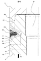
- FIG. 5A shows parts constituting the fuel boundary and its welded shape according to the embodiment of the fuel injection device of the present invention.
- the boundary between the high pressure fuel and the atmosphere is composed of two or more parts A and B.
- the small diameter outer diameter of the part with the stepped part and the inner diameter side of the other part are fitted and press-fitted, and the abutting surface Is contacted and positioned. 4 corresponds to the attachment portion 401 (first component) of the adapter 140, and the component B corresponds to the attachment portion 402 (second component) of the fixed core 107.
- Butt welding is performed from a direction close to the abutting surface between the first part A and the second part B, and a butt welding part 509 is formed.
- a long chamfer 501 is provided in a direction in which the inner diameter side corner of the abutting surface is orthogonal to the abutting surface.
- the butt weld 509 is formed so that the weld joint length 503 is larger than the abutting length 502 between the first part A and the second part B. That is, the welding direction front end portion of the butt welding portion 509 is positioned on the welding direction side with respect to the welding direction front end portion of the gap formed by the first component A, the second component B, and the butt welding portion 509 (right side in FIG. 5A). Direction).
- the weld penetration depth 505 of the butt weld 509 is set to a press-fit depth 504 or more.
- the press-fitting depth is the length of the butt weld 509 in the press-fitting direction.
- the weld penetration center 506 is positioned closer to the part to be fitted and press-fitted on the outer diameter side than the abutting surface 507. That is, the center portion 506 in the direction (vertical direction in FIG. 5A) orthogonal to the welding direction (right side direction in FIG. 5A) of the butt weld portion 509 is on the abutting direction side (lower side direction in FIG. 5A). Located in.
- the butt weld 509 represents a shape melted and re-solidified by welding.
- the surface 501 that forms a gap with the butt weld portion 509 of the first part A is formed by chamfering.
- first part A and the second part B are fixed by press-fitting on a side surface substantially orthogonal to the facing surface (the abutting surface 507), and a press-fitting surface (press-fit) that fixes the second part B and the first part A.
- a gap is formed on the press-fitting direction side (the lower side in FIG. 5A).
- the chamfered portion 501 is formed at the end of the first component A in the press-fitting direction in a direction away from the press-fitting surface (press-fitted portion) in the press-fitting direction (downward in FIG. 5A).
- the chamfered portion 501 is formed so that the length in the press-fitting direction is longer than the length in the direction orthogonal to the press-fitting direction (the left-right direction in FIG. 5A). Furthermore, it is desirable that the gap is formed so that the length in the abutting direction (the lower side in FIG. 5A) is longer than the length in the direction orthogonal to the abutting direction (the left-right direction in FIG. 5A).
- the angle 508 formed by the end of the welded portion with respect to the load direction 510 is large, the increase in stress due to stress concentration is reduced, and the strength of the welded portion can be maintained. It is.
- the angle 508 is preferably around 180 degrees, and if it is 45 degrees or more, it is possible to maintain a desired fixed strength in the fuel injection valve.
- the angle 511 formed by the chamfer 501 of the first part A is as small as possible so that the angle 508 formed by the top surface 512 of the butt weld 509 and the chamfer 501 is as large as possible.
- the press-fitting distance between the component A and the component B cannot be secured, so, for example, about 30 degrees (20 degrees ⁇ angle 511 ⁇ 40 degrees).
- the fuel injection device of the present embodiment is configured with two or more parts at the boundary between the high pressure fuel and the atmosphere, and is fitted on the small diameter side outer diameter of the part provided with the stepped portion and the inner diameter side of the other part.
- press fitting contact is made at the abutting surface and positioning is performed. It includes a portion where butt welding is performed from a direction nearly parallel to the abutting surface.
- the first part A fitted and press-fitted on the inner diameter side has a long chamfer in a direction in which the inner diameter side corner portion of the abutting surface is orthogonal to the abutting surface.
- the welding penetration depth is set to be equal to or greater than the thickness of the press-fitting portion of the first part A to be fitted and press-fitted on the inner diameter side, and the center in the welding press-fitting direction is fitted and press-fitted on the outer diameter side from the abutting surface. Located on the second part B side.
- FIG. 6A shows a case where the welding center position is shifted toward the first part A in the drawing with respect to the target.
- a slight gap 702 remains at the corner of the butt weld 509 and the second part B, which are melted and re-solidified metal after welding.
- This gap shape has a small angle 701 formed by the end of the welded portion with respect to the axial load 600 caused by the fuel pressure, so stress concentrates and increases the stress, thereby reducing the strength of the welded portion.
- the weld penetration center 506 needs to be positioned on the part to be fitted and press-fitted on the outer diameter side of the abutting surface 507.
- FIG. 6B shows the case where the penetration depth 505 is shallower than the press-fit depth 504.
- a part 704 of the metal 509 after melting and re-solidification may locally swell and protrude into the gap 705 between the first part A and the second part B.
- This gap shape has a small angle 703 formed by the end of the welded portion with respect to the axial load 600 caused by the fuel pressure, so stress concentrates and increases the stress, thereby reducing the strength of the welded portion.
- the weld penetration depth 505 needs to be deeper than the press-fit depth 504.
- the welding shape of the embodiment of the present invention shown in FIG. 5 is used, there is a merit that the first part A and the second part B do not require complicated shapes and the manufacturing cost of the parts is not increased. Further, since it is not necessary to change the position and angle of the penetration center 506 during laser welding, there is an advantage that the cost of the welding equipment is not increased. Further, since the position and angle of the penetration center 506 are not changed during laser welding, the time required for welding does not increase, and the cost increase of the welding equipment can be suppressed.
- the embodiment of the present invention shown in FIG. 5 minimizes the penetration amount of the butt weld and suppresses the occurrence of transient stress concentration with respect to the load while reducing the time and equipment cost required for welding.
- a butt-welding structure can be realized.
- this invention is not limited to the above-mentioned Example, Various modifications are included.
- the above-described embodiments have been described in detail for easy understanding of the present invention, and are not necessarily limited to those having all the configurations described.
- a part of the configuration of one embodiment can be replaced with the configuration of another embodiment, and the configuration of another embodiment can be added to the configuration of one embodiment.
Landscapes
- Engineering & Computer Science (AREA)
- Chemical & Material Sciences (AREA)
- Combustion & Propulsion (AREA)
- Mechanical Engineering (AREA)
- General Engineering & Computer Science (AREA)
- Physics & Mathematics (AREA)
- Electromagnetism (AREA)
- Manufacturing & Machinery (AREA)
- Analytical Chemistry (AREA)
- Fuel-Injection Apparatus (AREA)
Abstract
Description
可動ニードル部と電磁コアを少なくとも一部突き合わせ、突き合わせ部にYAGレーザ光を照射して突き合わせ面より長い距離を溶接することにより、耐久性の優れた燃料噴射弁を量産可能にして提供できる。
よって高燃圧に対応する燃料噴射弁では、固定コア107とアダプタ140の2部品に分割され、アダプタ140には固定コア107より降伏応力、引っ張り強さの大きな材料を使用し、固定コア107には磁気特性の優れた材料を使用し、2部品を径方向で圧入させた後、403aで全周溶接して固定される場合がある。
図2は燃料噴射弁内部に印加される燃料圧力に対する燃料噴射装置軸方向の荷重を算出したグラフである。従来、最高燃料圧力は例えば20MPaで使用されており、その際の燃圧によって燃料噴射弁の軸方向に印加される荷重は例えば1800Nである。燃料圧力を35MPaにすると燃圧荷重はおよそ1.5倍の3200Nとなる。また燃料圧力が35MPaのシステムでは安全の余裕度を考慮して、例えば燃料圧力55MPaまで構造強度を保つ必要があり、その場合の軸方向荷重はおおよそ7700Nにも達する。前述の通り、燃料噴射弁を構成する部品には、燃圧による軸方向荷重が伝達するため、燃圧の増加に伴い各部品に発生する応力は増加する。燃料噴射弁を構成する部品の形状、材料、溶接形状を従来から変更しない場合、強度の余裕度が減少する。一方で強度の大きい材料や複雑な溶接方法を使用することはコストの増加につながる。
次に、図1Aから図6Bを用いて、本発明の実施例による燃料噴射弁の構成を詳細に説明する。
噴孔カップ支持体101は直径が小さい小径筒状部22と直径が大きい大径筒状部23とを備えている。小径筒状部22の先端部分の内部に、案内部115、燃料噴射孔117を備えた噴孔カップ116(燃料噴射孔形成部材)が挿入または圧入され、噴孔カップ116の先端面の外周の縁部が全周溶接される。これにより、噴孔カップ116は、小径筒状部22に固定される。案内部115は可動子部114を構成する針弁114Aの先端に設けられた弁体先端部114Bが燃料噴射弁の軸方向に上下運動する際に、外周を案内する機能を有する。
図3Bは図3に記載の燃料噴射弁の重ね溶接部分の近傍460を拡大したものである。燃料圧力によってノズルホルダ23は外径方向、燃料噴射弁軸方向下向きに荷重305を受けるが、固定コア407は軸方向に固定されているため、重ね溶接部301に対して主に作用する荷重は燃料圧力によってノズルホルダ23が燃料噴射弁軸方向下向きになる。
燃料噴射弁のアダプタ140の取付部401と固定コア107の取付部402は径方向で接触し、圧入され、燃料を封止するために突合せ溶接部403で全周突き合わせ溶接されている。溶接前にアダプタ140の取付部401と固定コア107の取付部402部が圧入固定されているため、溶接時に生じるひずみによって生じるアダプタ140の倒れを抑制できる。
23…噴孔カップ支持体の大径筒状部
39…弁座シート部(シート部材のシート部)
43A…コネクタ
101…噴孔カップ支持体
102…可動子
103…ハウジング
104…コイルボビン
105…電磁コイル(ソレノイド)
107、407…固定コア(固定子)
107D…固定子貫通孔(燃料通路)
109…導体
110…スプリング
112…ゼロスプリング
113…針弁案内部(肩部)
114…可動子部
114A…針弁
114B…弁体先端部
114C…針弁の頭部(スプリングガイド用突起)
115…案内部116…噴孔カップ
117…燃料噴射孔
121…樹脂成形体
126…燃料通路
127…案内部
128…貫通孔
136…隙間
140…アダプタ(パイプ)
201…弁体先端の被案内部
202…噴孔カップの案内部
203…弁体先端の弁体シート部
215…ハウジングのテーパ面
251…プレート
301…重ね溶接部
302…重ね溶接中の境界面
303…境界面302の上端
304…境界面302の下端
305、510…荷重方向
401…アダプタ140の取付部
402…固定コア107の取付部
403…突合せ溶接部
501…面取り
502…突き当て長さ
503…溶接結合長
504…圧入深さ
505…溶接溶け込み深さ
506…溶接溶け込み中心
507…突き当て面
508、701、703…なす角
509…溶融、再凝固金属(突合せ溶接部)
601…燃料噴射弁内部
605、702、705…隙間
606、607、608、611、613…溶接形状
609…突合せ面
610、614…溶け込み深さ
612…部品Bの厚み
615…溶接部形状の端部
704…溶融、再凝固後の金属の一部
Claims (10)
- 第1部品と、前記第1部品の一面に対向する対向面を有する第2部品と、を備えた流量制御装置において、
前記第1部品の前記一面と前記第2部品の前記対向面との間において互いに接触する突き当て面と、
前記第1部品と前記第2部品との前記突き当て面において、前記突き当て面と沿うように形成された溶接部と、を備え、
前記溶接部と前記第1部品と前記第2部品とで空隙を形成し、かつ、前記溶接部の溶接方向先端部は突き当て面の溶接方向先端部に対して、溶接方向側に位置することを特徴とする流量制御装置。 - 請求項1に記載の流量制御装置において、
前記溶接部の溶接方向先端部は前記空隙の溶接方向先端部に対して溶接方向側に位置することを特徴とする流量制御装置。 - 請求項1に記載の流量制御装置において、
前記溶接部の溶接方向と直交する方向における中心部が前記突き当て面よりも突き当て方向側に位置することを特徴とする流量制御装置。 - 請求項1に記載の流量制御装置において、
前記第2部品のうち、前記第1部品との前記対向面とほぼ直交する側面において、前記第1部品と前記第2部品とを固定する圧入部を有し、
前記第2部品と前記第1部品との圧入部に対し圧入方向側に前記空隙が形成されることを特徴とする流量制御装置。 - 請求項1に記載の流量制御装置において、
前記第2部品のうち、前記第1部品との前記対向面とほぼ直交する側面において、前記第1部品と前記第2部品とを固定する圧入部を有し、
前記第1部品の圧入方向端部に圧入方向に向かうにつれて前記圧入部と離れる方向に形成される面取り部が形成されたことを特徴とする流量制御装置。 - 請求項1に記載の流量制御装置において、
前記第2部品のうち、前記第1部品との前記対向面とほぼ直交する側面において、前記第1部品と前記第2部品とを固定する圧入部を有し、
前記第1部品の圧入方向端部に圧入方向に向かうにつれて前記圧入部と離れる方向に形成される面取り部が形成され、
前記面取り部は圧入方向における長さが、前記圧入方向と直交する方向における長さに対し長くなるように形成されたことを特徴とする流量制御装置。 - 請求項1に記載の流量制御装置において、
前記空隙は突き当て方向における長さが、前記突き当て方向と直交する方向における長さに対し長くなるように形成されたことを特徴とする流量制御装置。 - 請求項1に記載の流量制御装置において、
前記溶接部のうち、前記空隙を形成する部分に引かれる接線と、前記第1部品のうち前記溶接部とで前記空隙を形成する面に引かれる接線とでなす角が45度以上であることを特徴とする流量制御装置。 - 請求項1に記載の流量制御装置において、
前記第2部品のうち、前記第1部品との前記対向面とほぼ直交する側面において、前記第1部品と前記第2部品とを固定する圧入部を有し、
前記第1部品の圧入方向端部に圧入方向に向かうにつれて前記圧入部と離れる方向に形成される面取り部が形成され、前記圧入部と前記面取り部とで形成される角度が20度以上、40度以下となるように構成されたことを特徴とする流量制御装置。 - 請求項1に記載の流量制御装置において、
流路の開閉を行う弁体と、
前記第2部材は磁気吸引力を生じさせる磁気コアで、
前記第1部材が前記磁気コアが前記弁体の移動方向において突き合わせられて固定される固定部材であることを特徴とする流量制御装置。
Priority Applications (4)
| Application Number | Priority Date | Filing Date | Title |
|---|---|---|---|
| US16/072,637 US10890147B2 (en) | 2016-03-28 | 2017-01-19 | Flow control device |
| DE112017000261.3T DE112017000261B4 (de) | 2016-03-28 | 2017-01-19 | Durchflussregelvorrichtung |
| CN201780018632.2A CN108779748B (zh) | 2016-03-28 | 2017-01-19 | 流量控制装置 |
| JP2018508425A JP6592587B2 (ja) | 2016-03-28 | 2017-01-19 | 流量制御装置 |
Applications Claiming Priority (2)
| Application Number | Priority Date | Filing Date | Title |
|---|---|---|---|
| JP2016-062973 | 2016-03-28 | ||
| JP2016062973 | 2016-03-28 |
Publications (1)
| Publication Number | Publication Date |
|---|---|
| WO2017168975A1 true WO2017168975A1 (ja) | 2017-10-05 |
Family
ID=59963005
Family Applications (1)
| Application Number | Title | Priority Date | Filing Date |
|---|---|---|---|
| PCT/JP2017/001633 Ceased WO2017168975A1 (ja) | 2016-03-28 | 2017-01-19 | 流量制御装置 |
Country Status (5)
| Country | Link |
|---|---|
| US (1) | US10890147B2 (ja) |
| JP (1) | JP6592587B2 (ja) |
| CN (1) | CN108779748B (ja) |
| DE (1) | DE112017000261B4 (ja) |
| WO (1) | WO2017168975A1 (ja) |
Cited By (1)
| Publication number | Priority date | Publication date | Assignee | Title |
|---|---|---|---|---|
| WO2019202829A1 (ja) * | 2018-04-20 | 2019-10-24 | 日立オートモティブシステムズ株式会社 | 流量制御装置の部品及び燃料噴射弁 |
Families Citing this family (3)
| Publication number | Priority date | Publication date | Assignee | Title |
|---|---|---|---|---|
| JP7167666B2 (ja) * | 2018-11-30 | 2022-11-09 | 株式会社デンソー | 燃料噴射弁 |
| JP7070459B2 (ja) * | 2019-02-12 | 2022-05-18 | 株式会社デンソー | 燃料流路部材、および、それを用いた燃料噴射弁 |
| CN116696631B (zh) * | 2023-06-21 | 2026-04-24 | 中国第一汽车股份有限公司 | 针阀间隙限位结构及喷油器 |
Citations (9)
| Publication number | Priority date | Publication date | Assignee | Title |
|---|---|---|---|---|
| JPH05164012A (ja) * | 1991-12-17 | 1993-06-29 | Mitsubishi Electric Corp | 燃料噴射装置及びその固定鉄心の製造方法 |
| JPH11166461A (ja) * | 1997-12-04 | 1999-06-22 | Keihin Corp | 電磁式燃料噴射弁 |
| JPH11193762A (ja) * | 1997-12-26 | 1999-07-21 | Hitachi Ltd | 電磁式燃料噴射弁装置およびその製造方法 |
| JP2001071161A (ja) * | 1999-08-31 | 2001-03-21 | Hitachi Ltd | レーザ溶接部品の製造方法 |
| JP2005240732A (ja) * | 2004-02-27 | 2005-09-08 | Keihin Corp | 電磁式燃料噴射弁およびその製造方法 |
| JP2006029259A (ja) * | 2004-07-20 | 2006-02-02 | Toyota Motor Corp | 燃料噴射弁 |
| JP2007218205A (ja) * | 2006-02-17 | 2007-08-30 | Hitachi Ltd | 電磁燃料噴射弁及びその組立て方法 |
| JP2012188977A (ja) * | 2011-03-10 | 2012-10-04 | Hitachi Automotive Systems Ltd | 燃料噴射装置 |
| JP2013164027A (ja) * | 2012-02-10 | 2013-08-22 | Hitachi Automotive Systems Ltd | 燃料噴射弁 |
Family Cites Families (4)
| Publication number | Priority date | Publication date | Assignee | Title |
|---|---|---|---|---|
| GB2262659B (en) | 1991-12-17 | 1995-08-23 | Mitsubishi Electric Corp | A fuel injection device and a method of making a fixed core therof |
| DE102006040650A1 (de) * | 2006-08-30 | 2008-03-13 | Robert Bosch Gmbh | Verfahren zum Fügen von Bauteilen mit geschlossenem Hohlquerschnitt |
| JP4491474B2 (ja) * | 2007-05-31 | 2010-06-30 | 日立オートモティブシステムズ株式会社 | 燃料噴射弁及びそのストローク調整方法 |
| JP5072745B2 (ja) * | 2008-07-07 | 2012-11-14 | 株式会社ケーヒン | 電磁式燃料噴射弁及びその製造方法 |
-
2017
- 2017-01-19 DE DE112017000261.3T patent/DE112017000261B4/de active Active
- 2017-01-19 JP JP2018508425A patent/JP6592587B2/ja not_active Expired - Fee Related
- 2017-01-19 US US16/072,637 patent/US10890147B2/en not_active Expired - Fee Related
- 2017-01-19 WO PCT/JP2017/001633 patent/WO2017168975A1/ja not_active Ceased
- 2017-01-19 CN CN201780018632.2A patent/CN108779748B/zh not_active Expired - Fee Related
Patent Citations (9)
| Publication number | Priority date | Publication date | Assignee | Title |
|---|---|---|---|---|
| JPH05164012A (ja) * | 1991-12-17 | 1993-06-29 | Mitsubishi Electric Corp | 燃料噴射装置及びその固定鉄心の製造方法 |
| JPH11166461A (ja) * | 1997-12-04 | 1999-06-22 | Keihin Corp | 電磁式燃料噴射弁 |
| JPH11193762A (ja) * | 1997-12-26 | 1999-07-21 | Hitachi Ltd | 電磁式燃料噴射弁装置およびその製造方法 |
| JP2001071161A (ja) * | 1999-08-31 | 2001-03-21 | Hitachi Ltd | レーザ溶接部品の製造方法 |
| JP2005240732A (ja) * | 2004-02-27 | 2005-09-08 | Keihin Corp | 電磁式燃料噴射弁およびその製造方法 |
| JP2006029259A (ja) * | 2004-07-20 | 2006-02-02 | Toyota Motor Corp | 燃料噴射弁 |
| JP2007218205A (ja) * | 2006-02-17 | 2007-08-30 | Hitachi Ltd | 電磁燃料噴射弁及びその組立て方法 |
| JP2012188977A (ja) * | 2011-03-10 | 2012-10-04 | Hitachi Automotive Systems Ltd | 燃料噴射装置 |
| JP2013164027A (ja) * | 2012-02-10 | 2013-08-22 | Hitachi Automotive Systems Ltd | 燃料噴射弁 |
Cited By (2)
| Publication number | Priority date | Publication date | Assignee | Title |
|---|---|---|---|---|
| WO2019202829A1 (ja) * | 2018-04-20 | 2019-10-24 | 日立オートモティブシステムズ株式会社 | 流量制御装置の部品及び燃料噴射弁 |
| US11313336B2 (en) | 2018-04-20 | 2022-04-26 | Hitachi Astemo, Ltd. | Component for flow rate control device, and fuel injection valve |
Also Published As
| Publication number | Publication date |
|---|---|
| DE112017000261B4 (de) | 2025-09-25 |
| CN108779748A (zh) | 2018-11-09 |
| JP6592587B2 (ja) | 2019-10-16 |
| US10890147B2 (en) | 2021-01-12 |
| JPWO2017168975A1 (ja) | 2018-10-11 |
| DE112017000261T5 (de) | 2018-09-27 |
| US20190040827A1 (en) | 2019-02-07 |
| CN108779748B (zh) | 2021-02-26 |
Similar Documents
| Publication | Publication Date | Title |
|---|---|---|
| JP4491474B2 (ja) | 燃料噴射弁及びそのストローク調整方法 | |
| JP2019082179A (ja) | 流量制御弁及び高圧燃料供給ポンプ | |
| JP5152024B2 (ja) | 燃料噴射弁 | |
| JP6232144B2 (ja) | 燃料噴射弁 | |
| JP6592587B2 (ja) | 流量制御装置 | |
| JP6219533B2 (ja) | 燃料噴射弁 | |
| US20170241389A1 (en) | Fuel injector | |
| JP6355765B2 (ja) | 燃料噴射弁 | |
| US7063279B2 (en) | Fuel injection valve | |
| US11313336B2 (en) | Component for flow rate control device, and fuel injection valve | |
| JPWO2019054036A1 (ja) | 流量制御装置、および流量制御装置の製造方法 | |
| JP6338662B2 (ja) | 燃料噴射弁 | |
| JP2017141725A (ja) | 高圧燃料供給ポンプ | |
| WO2017043211A1 (ja) | 燃料噴射装置 | |
| WO2019107126A1 (ja) | 燃料噴射装置 | |
| JPWO2018003559A1 (ja) | 燃料噴射弁 | |
| JP6655568B2 (ja) | 燃料噴射弁 | |
| JP2020002812A (ja) | 高圧燃料供給ポンプ及び高圧燃料供給ポンプの製造方法 | |
| WO2019225069A1 (ja) | 燃料ポンプ | |
| CN113423942A (zh) | 燃料流路部件及使用了该燃料流路部件的燃料喷射阀 |
Legal Events
| Date | Code | Title | Description |
|---|---|---|---|
| ENP | Entry into the national phase |
Ref document number: 2018508425 Country of ref document: JP Kind code of ref document: A |
|
| WWE | Wipo information: entry into national phase |
Ref document number: 112017000261 Country of ref document: DE |
|
| 121 | Ep: the epo has been informed by wipo that ep was designated in this application |
Ref document number: 17773525 Country of ref document: EP Kind code of ref document: A1 |
|
| 122 | Ep: pct application non-entry in european phase |
Ref document number: 17773525 Country of ref document: EP Kind code of ref document: A1 |
|
| WWG | Wipo information: grant in national office |
Ref document number: 112017000261 Country of ref document: DE |