WO2017164251A1 - Générateur de lumière ultraviolette extrême et procédé de commande de centroïde de lumière ultraviolette extrême - Google Patents
Générateur de lumière ultraviolette extrême et procédé de commande de centroïde de lumière ultraviolette extrême Download PDFInfo
- Publication number
- WO2017164251A1 WO2017164251A1 PCT/JP2017/011516 JP2017011516W WO2017164251A1 WO 2017164251 A1 WO2017164251 A1 WO 2017164251A1 JP 2017011516 W JP2017011516 W JP 2017011516W WO 2017164251 A1 WO2017164251 A1 WO 2017164251A1
- Authority
- WO
- WIPO (PCT)
- Prior art keywords
- target
- euv light
- extreme ultraviolet
- ultraviolet light
- center
- Prior art date
Links
- 238000000034 method Methods 0.000 title claims description 72
- 238000005259 measurement Methods 0.000 claims abstract description 56
- 230000001678 irradiating effect Effects 0.000 claims abstract description 9
- 230000005484 gravity Effects 0.000 claims description 169
- 238000011156 evaluation Methods 0.000 claims description 104
- 230000036278 prepulse Effects 0.000 claims description 62
- 238000012886 linear function Methods 0.000 claims description 6
- 238000012888 cubic function Methods 0.000 claims description 5
- 230000003287 optical effect Effects 0.000 description 92
- 238000001514 detection method Methods 0.000 description 60
- 230000008569 process Effects 0.000 description 55
- 238000005286 illumination Methods 0.000 description 27
- 238000010586 diagram Methods 0.000 description 26
- 230000000052 comparative effect Effects 0.000 description 16
- 238000012545 processing Methods 0.000 description 14
- 230000007246 mechanism Effects 0.000 description 13
- 230000000694 effects Effects 0.000 description 12
- 230000005540 biological transmission Effects 0.000 description 10
- 230000036544 posture Effects 0.000 description 10
- 230000005855 radiation Effects 0.000 description 8
- ATJFFYVFTNAWJD-UHFFFAOYSA-N Tin Chemical compound [Sn] ATJFFYVFTNAWJD-UHFFFAOYSA-N 0.000 description 4
- 230000003111 delayed effect Effects 0.000 description 4
- 230000006866 deterioration Effects 0.000 description 4
- 239000007769 metal material Substances 0.000 description 4
- 230000035945 sensitivity Effects 0.000 description 4
- 229910052718 tin Inorganic materials 0.000 description 4
- 230000008859 change Effects 0.000 description 3
- 238000011084 recovery Methods 0.000 description 3
- 230000005469 synchrotron radiation Effects 0.000 description 3
- 238000012546 transfer Methods 0.000 description 3
- 238000004364 calculation method Methods 0.000 description 2
- 239000000155 melt Substances 0.000 description 2
- 238000002844 melting Methods 0.000 description 2
- 230000008018 melting Effects 0.000 description 2
- 238000012986 modification Methods 0.000 description 2
- 230000004048 modification Effects 0.000 description 2
- 239000002245 particle Substances 0.000 description 2
- 239000004065 semiconductor Substances 0.000 description 2
- 229910052688 Gadolinium Inorganic materials 0.000 description 1
- ZOKXTWBITQBERF-UHFFFAOYSA-N Molybdenum Chemical compound [Mo] ZOKXTWBITQBERF-UHFFFAOYSA-N 0.000 description 1
- 229910052771 Terbium Inorganic materials 0.000 description 1
- 230000004913 activation Effects 0.000 description 1
- 230000015556 catabolic process Effects 0.000 description 1
- 238000011109 contamination Methods 0.000 description 1
- 238000006731 degradation reaction Methods 0.000 description 1
- 238000011161 development Methods 0.000 description 1
- 238000002474 experimental method Methods 0.000 description 1
- 239000010419 fine particle Substances 0.000 description 1
- UIWYJDYFSGRHKR-UHFFFAOYSA-N gadolinium atom Chemical compound [Gd] UIWYJDYFSGRHKR-UHFFFAOYSA-N 0.000 description 1
- 230000010365 information processing Effects 0.000 description 1
- 150000002500 ions Chemical class 0.000 description 1
- 239000000463 material Substances 0.000 description 1
- 239000011159 matrix material Substances 0.000 description 1
- 239000003595 mist Substances 0.000 description 1
- 239000003607 modifier Substances 0.000 description 1
- 229910052750 molybdenum Inorganic materials 0.000 description 1
- 239000011733 molybdenum Substances 0.000 description 1
- 230000007935 neutral effect Effects 0.000 description 1
- 230000002093 peripheral effect Effects 0.000 description 1
- 238000000206 photolithography Methods 0.000 description 1
- 230000002250 progressing effect Effects 0.000 description 1
- 238000012887 quadratic function Methods 0.000 description 1
- 229910052710 silicon Inorganic materials 0.000 description 1
- 239000010703 silicon Substances 0.000 description 1
- 238000004088 simulation Methods 0.000 description 1
- 239000007787 solid Substances 0.000 description 1
- GZCRRIHWUXGPOV-UHFFFAOYSA-N terbium atom Chemical compound [Tb] GZCRRIHWUXGPOV-UHFFFAOYSA-N 0.000 description 1
Images


Classifications
-
- H—ELECTRICITY
- H05—ELECTRIC TECHNIQUES NOT OTHERWISE PROVIDED FOR
- H05G—X-RAY TECHNIQUE
- H05G2/00—Apparatus or processes specially adapted for producing X-rays, not involving X-ray tubes, e.g. involving generation of a plasma
- H05G2/001—X-ray radiation generated from plasma
- H05G2/008—X-ray radiation generated from plasma involving a beam of energy, e.g. laser or electron beam in the process of exciting the plasma
-
- G—PHYSICS
- G01—MEASURING; TESTING
- G01J—MEASUREMENT OF INTENSITY, VELOCITY, SPECTRAL CONTENT, POLARISATION, PHASE OR PULSE CHARACTERISTICS OF INFRARED, VISIBLE OR ULTRAVIOLET LIGHT; COLORIMETRY; RADIATION PYROMETRY
- G01J1/00—Photometry, e.g. photographic exposure meter
- G01J1/02—Details
- G01J1/04—Optical or mechanical part supplementary adjustable parts
- G01J1/0407—Optical elements not provided otherwise, e.g. manifolds, windows, holograms, gratings
- G01J1/0411—Optical elements not provided otherwise, e.g. manifolds, windows, holograms, gratings using focussing or collimating elements, i.e. lenses or mirrors; Aberration correction
-
- G—PHYSICS
- G01—MEASURING; TESTING
- G01J—MEASUREMENT OF INTENSITY, VELOCITY, SPECTRAL CONTENT, POLARISATION, PHASE OR PULSE CHARACTERISTICS OF INFRARED, VISIBLE OR ULTRAVIOLET LIGHT; COLORIMETRY; RADIATION PYROMETRY
- G01J1/00—Photometry, e.g. photographic exposure meter
- G01J1/42—Photometry, e.g. photographic exposure meter using electric radiation detectors
- G01J1/4209—Photoelectric exposure meters for determining the exposure time in recording or reproducing
-
- G—PHYSICS
- G01—MEASURING; TESTING
- G01J—MEASUREMENT OF INTENSITY, VELOCITY, SPECTRAL CONTENT, POLARISATION, PHASE OR PULSE CHARACTERISTICS OF INFRARED, VISIBLE OR ULTRAVIOLET LIGHT; COLORIMETRY; RADIATION PYROMETRY
- G01J1/00—Photometry, e.g. photographic exposure meter
- G01J1/42—Photometry, e.g. photographic exposure meter using electric radiation detectors
- G01J1/4257—Photometry, e.g. photographic exposure meter using electric radiation detectors applied to monitoring the characteristics of a beam, e.g. laser beam, headlamp beam
-
- G—PHYSICS
- G01—MEASURING; TESTING
- G01J—MEASUREMENT OF INTENSITY, VELOCITY, SPECTRAL CONTENT, POLARISATION, PHASE OR PULSE CHARACTERISTICS OF INFRARED, VISIBLE OR ULTRAVIOLET LIGHT; COLORIMETRY; RADIATION PYROMETRY
- G01J1/00—Photometry, e.g. photographic exposure meter
- G01J1/42—Photometry, e.g. photographic exposure meter using electric radiation detectors
- G01J1/429—Photometry, e.g. photographic exposure meter using electric radiation detectors applied to measurement of ultraviolet light
-
- G—PHYSICS
- G03—PHOTOGRAPHY; CINEMATOGRAPHY; ANALOGOUS TECHNIQUES USING WAVES OTHER THAN OPTICAL WAVES; ELECTROGRAPHY; HOLOGRAPHY
- G03F—PHOTOMECHANICAL PRODUCTION OF TEXTURED OR PATTERNED SURFACES, e.g. FOR PRINTING, FOR PROCESSING OF SEMICONDUCTOR DEVICES; MATERIALS THEREFOR; ORIGINALS THEREFOR; APPARATUS SPECIALLY ADAPTED THEREFOR
- G03F7/00—Photomechanical, e.g. photolithographic, production of textured or patterned surfaces, e.g. printing surfaces; Materials therefor, e.g. comprising photoresists; Apparatus specially adapted therefor
- G03F7/70—Microphotolithographic exposure; Apparatus therefor
- G03F7/70008—Production of exposure light, i.e. light sources
- G03F7/70033—Production of exposure light, i.e. light sources by plasma extreme ultraviolet [EUV] sources
-
- H—ELECTRICITY
- H01—ELECTRIC ELEMENTS
- H01S—DEVICES USING THE PROCESS OF LIGHT AMPLIFICATION BY STIMULATED EMISSION OF RADIATION [LASER] TO AMPLIFY OR GENERATE LIGHT; DEVICES USING STIMULATED EMISSION OF ELECTROMAGNETIC RADIATION IN WAVE RANGES OTHER THAN OPTICAL
- H01S3/00—Lasers, i.e. devices using stimulated emission of electromagnetic radiation in the infrared, visible or ultraviolet wave range
- H01S3/005—Optical devices external to the laser cavity, specially adapted for lasers, e.g. for homogenisation of the beam or for manipulating laser pulses, e.g. pulse shaping
- H01S3/0071—Beam steering, e.g. whereby a mirror outside the cavity is present to change the beam direction
Definitions
- This disclosure relates to an extreme ultraviolet light generation apparatus and a method for controlling the position of the center of gravity of extreme ultraviolet light.
- an LPP Laser Produced Plasma
- DPP discharge Produced Plasma
- SR Synchrotron-Radiation
- An extreme ultraviolet light generation apparatus measures a plurality of extreme ultraviolet light energies generated by irradiating a target supplied to a predetermined region in a chamber with laser light from different directions.
- the EUV light sensor, the irradiation position adjusting unit for adjusting the irradiation position of the laser beam to the target supplied to the predetermined area, and the center position of the extreme ultraviolet light specified from the measurement results of the plurality of EUV light sensors are the target center position
- a control unit that controls the irradiation position adjusting unit to control the irradiation position adjusting unit so that the irradiation position is scanned according to a plurality of scanning levels that are different from each other.
- the target barycentric position is calibrated based on the measurement results obtained by each.
- a method for controlling the position of the center of gravity of extreme ultraviolet light is a method for controlling the position of the center of gravity of extreme ultraviolet light generated by irradiating a target with laser light, the positions being different from each other.
- a first step of scanning the irradiation position of the laser beam on the target according to a plurality of scanning levels and acquiring energy of extreme ultraviolet light at each of the plurality of scanning levels, and a plurality of scannings from the energy acquired by the first step The target center of gravity of the center of gravity position based on at least one of the second step of specifying the evaluation value of the center of gravity position at each level, the energy acquired by the first step, and the evaluation value specified by the second step A third step of calibrating the position.
- FIG. 1 is a diagram for explaining the configuration of an EUV light generation apparatus of a comparative example.
- FIG. 2 is a diagram for explaining the arrangement of the EUV light sensors shown in FIG.
- FIG. 3 shows a view of the arrangement of the EUV light sensor shown in FIG. 2 as viewed from the opposite direction of the X-axis direction.
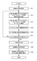
- FIG. 4 is a flowchart for explaining the calibration process of the target center-of-gravity position executed by the control unit according to the first embodiment.
- FIG. 5 shows an example of the scanning level group set in step S1 of FIG.
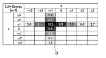
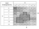
- FIG. 6 shows an example of an energy distribution diagram of the EUV light created in step S7 of FIG.
- FIG. 1 is a diagram for explaining the configuration of an EUV light generation apparatus of a comparative example.
- FIG. 2 is a diagram for explaining the arrangement of the EUV light sensors shown in FIG.
- FIG. 3 shows a view of the arrangement of the EUV light sensor shown in FIG. 2 as viewed from the opposite direction of the
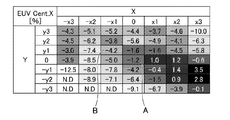
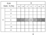
- FIG. 7 shows an example of a distribution diagram of evaluation values in the X-axis coordinate component of the gravity center position of EUV light created in step S7 of FIG.
- FIG. 8 shows an example of a distribution diagram of evaluation values in the Y-axis coordinate component of the gravity center position of EUV light created in step S7 of FIG.
- FIG. 9 shows a plurality of scanning levels arranged along the X-axis and the Y-axis with the scanning level A shown in FIG. 6 as the center, and measurement results of the EUV light sensor stored in association with these scanning levels. It shows.
- FIG. 10 shows a plurality of scanning levels arranged along the X axis with the scanning level A shown in FIG.
- FIG. 6 shows the center, and the X-axis coordinates of the gravity center position of EUV light stored in association with these scanning levels.
- the evaluation value in a component is shown.
- 11 shows a plurality of scanning levels arranged along the Y axis with the scanning level A shown in FIG. 6 as the center, and the Y-axis coordinates of the gravity center position of EUV light stored in association with these scanning levels.
- the evaluation value in a component is shown.
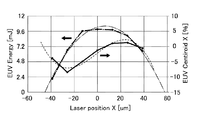
- FIG. 12 shows the energy distribution of EUV light and the evaluation value distribution of the center of gravity in the direction along the X-axis.
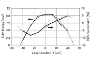
- FIG. 13 shows the EUV light energy distribution and the distribution of evaluation values of the center of gravity in the direction along the Y-axis.
- FIG. 14 shows a plurality of scanning levels arranged along the X axis and the Y axis with the scanning level B shown in FIG. 6 as the center, and measurement results of the EUV light sensor stored in association with these scanning levels. It shows. 15 shows a plurality of scanning levels arranged along the X axis as the center of the scanning level B shown in FIG. 6, and the X-axis coordinate component of the gravity center position of EUV light stored in association with these scanning levels. The evaluation value is shown.
- FIG. 16 shows a plurality of scanning levels arranged along the Y axis with the scanning level B shown in FIG. 6 as the center, and the Y-axis coordinates of the gravity center position of EUV light stored in association with these scanning levels. The evaluation value in a component is shown.
- FIG. 17 shows the energy distribution of EUV light and the distribution of evaluation values of the center of gravity position in the direction along the X axis with the scanning level B as the center.
- FIG. 18 shows the EUV light energy distribution in the direction along the Y axis with the scanning level B as the center, and the evaluation value distribution of the center of gravity position.
- FIG. 19 is a diagram for explaining a configuration of an EUV light generation system including the EUV light generation apparatus according to the third embodiment.
- FIG. 20 is a flowchart for explaining the calibration process of the target center-of-gravity position executed by the control unit according to the third embodiment.
- FIG. 21 is a flowchart for explaining the timing when the control unit according to the fourth embodiment executes the calibration process of the target gravity center position.
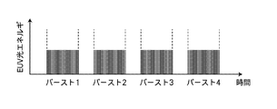
- FIG. 22 is a diagram for explaining burst emission of EUV light performed in the fifth embodiment.
- FIG. 23 shows an example of a distribution map of the EUV light energy variation index measured in the fifth embodiment.
- FIG. 24 shows an example of a distribution diagram of evaluation values related to the X-axis coordinate component of the gravity center position of EUV light measured in the fifth embodiment.
- FIG. 25 shows an example of a distribution diagram of evaluation values related to the Y-axis coordinate component of the gravity center position of EUV light measured in the fifth embodiment.
- FIG. 26 shows a plurality of scanning levels arranged along the X axis and the Y axis with the scanning level A shown in FIG. 23 as the center, and a variation index of EUV light energy stored in association with these scanning levels. It shows.
- FIG. 23 shows an example of a distribution map of the EUV light energy variation index measured in the fifth embodiment.
- FIG. 24 shows an example of a distribution diagram of evaluation values related to the X-axis coordinate component of the gravity center position
- FIG. 27 shows a plurality of scanning levels arranged along the X axis with the scanning level A shown in FIG. 23 as the center, and the X-axis coordinates of the gravity center position of EUV light stored in association with these scanning levels.
- the evaluation value regarding a component is shown.
- FIG. 28 shows a plurality of scanning levels arranged along the Y axis with the scanning level A shown in FIG. 23 as the center, and the Y-axis coordinates of the gravity center position of EUV light stored in association with these scanning levels.
- FIG. 29 shows an example in which the distribution index distribution of EUV light energy in the direction along the X axis and the evaluation value distribution of the EUV light barycentric position are approximated by curves, respectively.
- FIG. 30 shows an example in which the EUV light energy variation index distribution in the direction along the Y axis and the evaluation value distribution of the EUV light barycentric position are approximated by curves.
- FIG. 31 is a diagram for explaining the calibration process of the target center-of-gravity position in the fifth embodiment.
- FIG. 32 is a diagram for explaining the calibration process of the target center-of-gravity position in the first embodiment.
- FIG. 33 is a diagram for explaining the calibration process of the target center-of-gravity position in the sixth embodiment.
- FIG. 34 is a diagram for explaining the calibration process of the target center-of-gravity position in the seventh embodiment.
- the “target” is an object to be irradiated with laser light introduced into the chamber.
- the target irradiated with the laser light is turned into plasma and emits light including EUV light.
- the “plasma generation region” is a predetermined region in the chamber.
- the plasma generation region is a region where the target output to the chamber is irradiated with laser light and the target is turned into plasma.
- the “target trajectory” is a path along which the target output in the chamber travels. The target trajectory intersects the optical path of the laser light introduced into the chamber in the plasma generation region.
- the “optical path axis” is an axis passing through the center of the beam cross section of the laser light along the traveling direction of the laser light.
- the “optical path” is a path through which the laser light passes.
- the optical path includes an optical path axis.
- the “Z-axis direction” is a traveling direction of the laser light when the laser light introduced into the chamber travels toward the plasma generation region.
- the Z-axis direction may be substantially the same as the direction in which the EUV light generation apparatus outputs EUV light.
- the “Y-axis direction” is a direction opposite to the direction in which the target supplier outputs the target into the chamber.
- the Y-axis direction is a direction perpendicular to the X-axis direction and the Z-axis direction.
- the “X-axis direction” is a direction perpendicular to the Y-axis direction and the Z-axis direction.
- “Burst light emission” by the EUV light generation apparatus is to emit EUV light repeatedly at a relatively high frequency for a predetermined period.
- the predetermined period is also referred to as a “burst light emission period”.
- this burst light emission period is set to repeat with a predetermined pause period in between. That is, during each burst emission period, a group of EUV light that emits pulses at a high frequency is output.
- “Scanning level” refers to each of a plurality of different scanning positions when the laser beam is scanned within the irradiation position of the laser beam on the target.
- a comparative example of the EUV light generation apparatus 1 will be described with reference to FIGS. 1 to 3.
- the EUV light generation apparatus 1 of the comparative example is an LPP type EUV light generation apparatus.
- the EUV light generation apparatus 1 is used together with at least one laser apparatus 3.
- a system including the EUV light generation apparatus 1 and the laser apparatus 3 is also referred to as an EUV light generation system 11.
- the EUV light generation apparatus 1 generates plasma 275 of the target 27 by irradiating the target 27 with at least one pulsed laser light 31 output from the laser apparatus 3.
- the generated plasma 275 emits radiation light 276.
- the emitted light 276 includes various wavelengths of light in addition to the EUV light 277.
- the EUV light generation apparatus 1 collects the EUV light 277 included in the radiation light 276 and outputs it to the exposure apparatus 9. In this way, the EUV light generation apparatus 1 can generate the EUV light 277.
- FIG. 1 is a diagram for explaining a configuration of an EUV light generation apparatus 1 of a comparative example.
- the EUV light generation apparatus 1 of the comparative example includes a chamber 2, a laser light condensing optical system 22, an EUV light condensing optical system 23, a connection unit 24, and a laser light transmission optical system 33.
- the EUV light generation apparatus 1 of the comparative example includes a target supply device 25, a stage 26, a target recovery device 28, a target detection sensor 41, an EUV light sensor 43, and a control unit 8.
- the chamber 2 is a container in which plasma 275 is generated from the target 27 and EUV light 277 is generated by irradiating the target 27 supplied inside with the pulsed laser light 31.
- the wall 211 of the chamber 2 forms an internal space of the chamber 2 and isolates the internal space of the chamber 2 from the outside.
- the wall 211 is provided with a window 215 for introducing the pulsed laser light 31 into the chamber 2.
- the chamber 2 includes a target supply path 212 for supplying the target 27 into the chamber 2.
- the laser light transmission optical system 33 is an optical system that introduces the pulsed laser light 31 output from the laser device 3 into the chamber 2 through the window 215.
- the laser light transmission optical system 33 is disposed outside the chamber 2.
- the laser beam transmission optical system 33 is disposed on the optical path of the pulse laser beam 31 output from the laser device 3 and between the laser device 3 and the window 215.
- the laser light transmission optical system 33 includes a high reflection mirror 331 and a high reflection mirror 332.
- Each of the high reflection mirrors 331 and 332 is mounted on a stage (not shown) that adjusts at least one of their positions and postures. The operation of the stage on which the high reflection mirrors 331 and 332 are mounted is controlled by the control unit 8.
- the laser beam condensing optical system 22 is an optical system that condenses the pulsed laser beam 31 introduced into the chamber 2 through the window 215 in the plasma generation region R1.
- the laser beam condensing optical system 22 is disposed inside the chamber 2.
- the laser beam condensing optical system 22 is disposed on the optical path of the pulsed laser beam 31 transmitted through the window 215 and between the window 215 and the plasma generation region R1.
- the laser beam focusing optical system 22 includes a laser beam focusing mirror 221 and a manipulator 224.
- the laser beam condensing mirror 221 reflects the pulsed laser beam 31 transmitted through the window 215 toward the plasma generation region R1.
- the laser beam condensing mirror 221 condenses the reflected pulse laser beam 31 in the plasma generation region R1.
- the laser beam condensing mirror 221 is mounted on the manipulator 224.
- the laser beam condensing mirror 221 is configured using an off-axis parabolic mirror 222 and a flat mirror 223.
- the manipulator 224 is a mechanism that adjusts at least one of the position and posture of the laser beam focusing mirror 221.
- the manipulator 224 is a mechanism that adjusts at least one of the position and posture of the laser beam focusing mirror 221 so that the pulse laser beam 31 is irradiated onto the target 27 in the plasma generation region R1.
- the driving of the manipulator 224 is controlled by the control unit 8.
- the manipulator 224 may be a mechanism that moves the laser beam collector mirror 221 in a direction along at least one of the X axis and the Y axis.
- the manipulator 224 may be a mechanism that moves the laser beam focusing mirror 221 in a direction along the Z axis in addition to the X axis and the Y axis.
- the manipulator 224 may be a stage that is a mechanism that adjusts at least one of the position and posture of the laser beam focusing mirror 221.
- the EUV light condensing optical system 23 is an optical system that collects the EUV light 277 included in the radiation light 276 and condenses it at the intermediate condensing point IF.
- the EUV light condensing optical system 23 is disposed inside the chamber 2.
- the EUV light condensing optical system 23 includes an EUV light condensing mirror 231.
- the EUV light collector mirror 231 selectively reflects the EUV light 277 out of the radiated light 276 emitted from the plasma 275 in the plasma generation region R1.
- the EUV light condensing mirror 231 condenses the selectively reflected EUV light 277 at an intermediate condensing point IF located in the connection unit 24.
- the reflective surface of the EUV light collector mirror 231 is formed of, for example, a multilayer reflective film in which molybdenum and silicon are alternately stacked.
- the reflection surface of the EUV light collector mirror 231 is formed by a part of a spheroid having first and second focal points, for example.
- the EUV light collector mirror 231 is disposed such that the first focal point is located in the plasma generation region R1 and the second focal point is located at the intermediate focal point IF.
- a through hole 232 is formed at the center of the EUV light collector mirror 231.
- the through hole 232 is a hole for allowing the pulse laser beam 31 reflected by the laser beam focusing mirror 221 to pass toward the plasma generation region R1.
- the connection unit 24 is a connection unit between the chamber 2 and the exposure apparatus 9.
- the connection unit 24 includes a gate valve (not shown) for outputting the EUV light 277 condensed at the intermediate condensing point IF to the exposure apparatus 9.
- the gate valve included in the connection unit 24 hermetically communicates or isolates the inside of the chamber 2 and the inside of the exposure apparatus 9.
- a wall 241 is provided inside the connecting portion 24.
- An aperture 242 is formed in the wall 241. The aperture 242 is formed so as to be positioned at the intermediate condensing point IF.
- the target supply unit 25 is a device that melts the target 27 supplied into the chamber 2 and outputs it in the form of droplets toward the plasma generation region R1.
- the target supply unit 25 is a device that outputs the target 27 by a so-called continuous jet method.
- the target 27 supplied by the target supplier 25 is made of a metal material.
- the metal material forming the target 27 is a material including tin, terbium, gadolinium, or a combination of any two or more thereof.
- the metal material forming the target 27 is tin.
- the target supply unit 25 is mounted on the stage 26.
- the target supply unit 25 includes a tank 251, a nozzle 252, a heater 253, a pressure regulator 254, and a piezo element 255.
- the operation of the target supplier 25 is controlled by the control unit 8.
- the stage 26 is a mechanism that adjusts the position of the target supply unit 25.
- the stage 26 is a mechanism that moves the target supply unit 25 in a direction along at least one of the X axis and the Z axis.
- the stage 26 is a mechanism that adjusts the position of the target supply unit 25 so that the target 27 output from the target supply unit 25 is supplied to the plasma generation region R1.
- the driving of the stage 26 is controlled by the control unit 8.
- the target recovery device 28 is a device that recovers the target 27 that has not been irradiated with the pulse laser beam 31 among the targets 27 output into the chamber 2.
- the target collector 28 is provided on the wall 211 of the chamber 2 on the extension line of the target trajectory Q.
- the target detection sensor 41 is a sensor that detects the target 27 that passes through the target detection region R2.
- the target detection region R2 is a predetermined region in the chamber 2, and is a region located at a predetermined position on the target trajectory Q between the target supplier 25 and the plasma generation region R1.
- the target detection sensor 41 includes an illumination unit 410 and a detection unit 420.
- the illumination unit 410 and the detection unit 420 are connected to the wall 211 of the target supply path 212 via a window 216 and a window 217, respectively.
- the illumination part 410 and the detection part 420 are arrange
- the illumination unit 410 and the detection unit 420 are arranged such that the illumination optical axis of the illumination unit 410 and the detection optical axis of the detection unit 420 are substantially coaxial with each other and pass through the target detection region R2, as shown in FIG.
- the illumination optical axis of the illumination unit 410 is an optical path axis of illumination light output from the illumination unit 410 toward the target detection region R2.
- the detection optical axis of the detection unit 420 is an optical path axis of the illumination light detected by the detection unit 420 among the illumination light output from the illumination unit 410 toward the target detection region R2.
- the illumination unit 410 outputs illumination light toward the target detection region R2 so as to illuminate the target 27 that passes through the target detection region R2.
- the illumination unit 410 is configured using a light source 411 and an illumination optical system 412.
- the detection unit 420 detects the target 27 passing through the target detection region R2 by detecting the light intensity of the illumination light output so as to illuminate the target 27 passing through the target detection region R2.
- the detection unit 420 is configured using an optical sensor 421 and a light receiving optical system 422.
- the EUV light sensor 43 is a sensor that measures the energy of the EUV light 277 contained in the radiation light 276 emitted from the plasma 275.
- the EUV light sensor 43 is composed of a plurality of EUV light sensors 43. Each of the plurality of EUV light sensors 43 measures the energy of the EUV light 277 from different directions, and transmits the measured value to the control unit 8. Each operation of the plurality of EUV light sensors 43 is controlled by the control unit 8. A detailed configuration of the EUV light sensor 43 will be described later with reference to FIGS. 2 and 3.
- the control unit 8 comprehensively controls the operation of each component of the EUV light generation system 11 based on various commands from the exposure apparatus 9 that is an external apparatus.
- the control unit 8 controls the laser device 3 and controls the output of the pulse laser beam 31 from the laser device 3.
- the control unit 8 controls the target supplier 25 and controls the output of the target 27 from the target supplier 25.
- the control unit 8 controls a stage (not shown) on which the high reflection mirrors 331 and 332 are mounted, and controls at least one of the positions and postures of the high reflection mirrors 331 and 332.
- the control unit 8 controls the manipulator 224 to control at least one of the position and posture of the laser beam focusing mirror 221. Thereby, the control part 8 controls the condensing position of the pulsed laser beam 31 in the plasma generation region R1.
- the control unit 8 controls the stage 26 and controls the position of the target supply unit 25. Thereby, the control unit 8 controls the position of the target 27 supplied to the plasma generation region R1.
- the control unit 8 is composed of a computer in which hardware such as a processor and software such as a program module are combined. Information processing by software included in the control unit 8 is specifically realized by using hardware included in the control unit 8.
- the control unit 8 controls the target supply unit 25 to output the target 27 from the target supply unit 25 toward the plasma generation region R1. Specifically, the control unit 8 heats the heater 253 of the target supply unit 25 to a temperature equal to or higher than the melting point of the target 27 and melts the solid target 27 stored in the tank 251 of the target supply unit 25.
- the control unit 8 heats the heater 253 at a temperature of 250 ° C. or more and 290 ° C. or less, for example.
- the control unit 8 controls the pressure regulator 254 of the target supply unit 25 to apply a predetermined pressure to the target 27 in the tank 251 so that the target 27 in the tank 251 is continuously output from the nozzle 252 at a predetermined speed.
- the control unit 8 vibrates the piezo element 255 of the target supplier 25 with a predetermined waveform, divides the continuously output target 27 at a predetermined period to form a droplet-shaped target 27, and generates a predetermined frequency from the nozzle 252. To output.
- the target 27 output into the chamber 2 travels on the target trajectory Q in the form of a droplet and passes through the target detection region R2.
- the target 27 that has passed through the target detection region R2 is supplied to the plasma generation region R1.
- the target detection sensor 41 detects the timing at which the target 27 has passed through the target detection region R2. Specifically, the light source 411 of the illumination unit 410 outputs illumination light toward the target detection region R2 via the illumination optical system 412 so as to illuminate the target 27 that passes through the target detection region R2.
- the optical sensor 421 of the detection unit 420 detects the illumination light output to the target detection region R2 via the light receiving optical system 422, thereby detecting the target 27 that passes through the target detection region R2.
- the light intensity of the illumination light detected by the optical sensor 421 can decrease every time the target 27 passes through the target detection region R2.
- the optical sensor 421 generates an output signal corresponding to the change in the detected light intensity of the illumination light, and transmits the output signal to the control unit 8. Note that an output signal corresponding to a change in the light intensity of the illumination light detected by the optical sensor 421 is also referred to as a passage timing signal.
- the control unit 8 receives the passage timing signal transmitted from the target detection sensor 41.
- the control unit 8 determines that the timing at which the passage timing signal is lower than the predetermined threshold is the timing at which the target 27 has passed through the target detection region R2. That is, the control unit 8 specifies the timing at which the target 27 has passed through the target detection region R2 based on the detection result of the target detection sensor 41.
- the control unit 8 generates a target detection signal indicating that the target 27 has passed through the target detection region R2 at a timing when the passage timing signal becomes lower than a predetermined threshold. Note that the timing at which the target 27 passes through the target detection region R2 is also simply referred to as the passage timing of the target detection region R2.
- the control unit 8 transmits a trigger signal that gives an opportunity to output the pulsed laser light 31 to the laser device 3 at a timing delayed by a delay time Td from the timing at which the target detection signal is generated. That is, the control unit 8 causes the laser device 3 to output the pulse laser beam 31 at a timing obtained by adding the delay time Td to the passing timing of the target detection region R2.
- the delay time Td is a time for making the timing at which the pulse laser beam 31 is focused on the plasma generation region R1 substantially coincide with the timing at which the target 27 is supplied to the plasma generation region R1.
- the delay time Td defines the timing at which the pulse laser beam 31 is irradiated to the target 27 supplied to the plasma generation region R1.
- the delay time Td is stored in the control unit 8 in advance. Note that the irradiation timing of the pulse laser beam 31 to the target 27 supplied to the plasma generation region R ⁇ b> 1 is also simply referred to as the irradiation timing of the pulse laser beam 31.
- the laser device 3 outputs a pulse laser beam 31 when receiving the trigger signal.
- the pulsed laser beam 31 output from the laser device 3 is reflected by the high reflection mirrors 331 and 332 of the laser beam transmission optical system 33, passes through the window 215, and is introduced into the chamber 2.
- the pulsed laser beam 31 introduced into the chamber 2 is focused on the plasma generation region R1 by the laser beam focusing optical system 22.
- the pulse laser beam 31 focused on the plasma generation region R1 is applied to the target 27 supplied to the plasma generation region R1.
- the target 27 supplied to the plasma generation region R ⁇ b> 1 is turned into plasma when irradiated with the pulse laser beam 31, and emits radiation light 276.
- the EUV light 277 included in the radiation light 276 is selectively reflected by the EUV light condensing mirror 231 of the EUV light condensing optical system 23 and is condensed at the intermediate condensing point IF of the connection unit 24.
- the EUV light 277 collected at the intermediate focusing point IF is output toward the exposure apparatus 9.
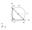
- FIG. 2 is a diagram for explaining the arrangement of the EUV light sensors 43 shown in FIG.
- FIG. 3 shows a view of the arrangement of the EUV light sensor 43 shown in FIG. 2 viewed from the direction opposite to the X-axis direction.
- the plurality of EUV light sensors 43 according to the comparative example includes at least three EUV light sensors 43.
- the plurality of EUV light sensors 43 are configured by, for example, EUV light sensors 43 a to 43 c.
- Each of the plurality of EUV light sensors 43a to 43c is provided on the wall 211 of the chamber 2 so as to face the plasma generation region R1 from different directions.
- Each of the plurality of EUV light sensors 43a to 43c is arranged so as not to block the optical path of the EUV light 277 reflected by the EUV light collector mirror 231.
- Each of the plurality of EUV light sensors 43 a to 43 c is disposed along the outer peripheral edge of the EUV light collector mirror 231.
- the plurality of EUV sensor lights 43a to 43c are arranged equidistant from each other with respect to the plasma generation region R1 so that a difference in energy measured by the plasma 275 when the plasma 275 is generated in the plasma generation region R1 is reduced. .
- Each of the plurality of EUV light sensors 43a to 43c is arranged at a position where it is easy to evaluate the position of the center of gravity of the EUV light 277.
- the plurality of EUV light sensors 43a to 43c are arranged at the vertices of a right isosceles triangle as shown in FIG.
- the midpoint of its long side is located in the plasma generation region R1
- its apex angle is located on the Z axis
- its two short sides are on the X axis and Y axis. They are right-angled isosceles triangles arranged along each.
- the EUV light sensor 43a is the EUV light sensor 43 arranged at the apex located on the axis along the Y axis of the right isosceles triangle shown in FIG.
- the EUV light sensor 43b is the EUV light sensor 43 arranged at the apex located on the axis along the X axis of the right isosceles triangle shown in FIG.
- the EUV light sensor 43c is the EUV light sensor 43 disposed at the apex located on the Z-axis of the right isosceles triangle shown in FIG.
- the gravity center position of the EUV light 277 is the gravity center position of the energy distribution of the EUV light 277. That is, the gravity center position of the EUV light 277 is a weighted average position in the energy distribution of the EUV light 277.
- the position of the center of gravity of the EUV light 277 is a spatial position specified from a plurality of measurement values obtained by measuring the energy of the EUV light 277 with the plurality of EUV light sensors 43a to 43c.
- the position of the center of gravity of the EUV light 277 is an index reflecting the irradiation position of the pulse laser light 31 on the target 27 supplied to the plasma generation region R1.
- the position of the center of gravity of the EUV light 277 is an index for evaluating whether the irradiation condition of the pulsed laser light 31 is a condition that satisfies the performance of the EUV light 277. Controlling the position of the center of gravity of the EUV light 277 to be the target position of the center of gravity means that the target 27 is appropriately irradiated with the pulse laser beam 31.
- the target gravity center position is, for example, a predetermined position in the plasma generation region R1.
- the control unit 8 defines the calculated value of Equation 1 as an evaluation value indicating an index for evaluating the X-axis coordinate component at the center of gravity position of the EUV light 277.
- the control unit 8 defines the calculated value of Expression 2 as an evaluation value indicating an index for evaluating the Y-axis coordinate component at the center of gravity position of the EUV light 277.
- This definition of the evaluation value is based on the premise that the target center-of-gravity position of the EUV light 277 is equidistant from each of the EUV light sensors 43a, 43b, and 43a shown in FIG.
- E1 is a measurement value of the EUV light sensor 43a.
- E2 is a measurement value of the EUV light sensor 43b.
- E3 is a measurement value of the EUV light sensor 43c.
- EUVCentroid_x is a value obtained by standardizing the deviation between the X-axis coordinate component at the center of gravity position of the current EUV light 277 and the X-axis coordinate component at the target center of gravity position.
- EUV Centroid_x indicates the uneven distribution of the energy distribution of the EUV light 277 in the direction along the X axis.
- EUVCentroid_y is a value obtained by normalizing the deviation between the Y-axis coordinate component at the center of gravity position of the current EUV light 277 and the Y-axis coordinate component at the target center of gravity position.
- EUV Centroid_y indicates the uneven distribution of the energy distribution of the EUV light 277 in the direction along the Y axis.
- the control unit 8 is configured to execute EUV light barycenter control.
- the EUV light center of gravity control is a laser beam condensing optical system 22 so that the center of gravity position of the EUV light 277 becomes a target center of gravity position based on the measurement results of the plurality of EUV light sensors 43a to 43c during generation of the EUV light 277. Is controlled by a feedback method.
- the control unit 8 has a function of executing the following processing as EUV light gravity center control.
- the control unit 8 transmits the first gate signal to each of the plurality of EUV light sensors 43a to 43c at a timing delayed by a predetermined delay time from the timing at which the target detection signal is generated.
- the first gate signal is a signal that gives an opportunity to measure the energy of the EUV light 277 to each of the plurality of EUV light sensors 43a to 43c.
- each of the EUV light sensors 43 a to 43 c measures the energy of the EUV light 277 and transmits the measured values E1 to E3 to the control unit 8.
- the control unit 8 evaluates the position of the center of gravity of the EUV light 277 using Equation 1 and Equation 2.
- the control unit 8 specifies the deviation between the current gravity center position of the EUV light 277 and the target gravity center position from the calculated values of Equation 1 and Equation 2.
- the control unit 8 sets the target irradiation position of the irradiation position of the pulse laser light 31 on the target 27 supplied to the plasma generation region R1 so that the gravity center position of the EUV light 277 becomes the target gravity center position.
- the control part 8 controls the laser beam condensing optical system 22 according to the set target irradiation position.
- the control unit 8 calculates a deviation between the current irradiation position of the pulsed laser light 31 on the target 27 supplied to the plasma generation region R1 and the target irradiation position of the pulsed laser light 31 according to the target center-of-gravity position. Identify. And the control part 8 specifies the deviation of the condensing position of the present pulsed laser beam 31 and the target condensing position of the pulsed laser beam 31 according to the target irradiation position. Then, the control unit 8 determines the driving amount of the manipulator 224 such that there is no deviation at the condensing position of the pulse laser beam 31. The control unit 8 drives the manipulator 224 according to the determined drive amount, and moves the condensing position of the pulse laser beam 31.
- control unit 8 can substantially match the irradiation position of the pulse laser beam 31 with respect to the target 27 supplied to the plasma generation region R1 to the target irradiation position, and can substantially match the gravity center position of the EUV light 277 to the target gravity center position.
- the control unit 8 drives the above-described stage on which the high-reflection mirror 331 is mounted and the above-described stage on which the high-reflection mirror 332 is mounted, instead of the manipulator 224, so that the pulse laser beam 31 is driven.
- the condensing position may be moved.
- the control unit 8 also includes the above-described stage on which the manipulator 224 and the high-reflecting mirror 331 are mounted, and the above-described stage on which the high-reflecting mirror 332 is mounted, according to the moving amount and moving speed of the condensing position of the pulse laser beam 31. Any one of the stages may be driven.
- the control unit 8 executes the EUV light barycenter control, the relative positional relationship between the position of the target 27 supplied to the plasma generation region R1 and the focused position of the pulse laser beam 31 becomes an appropriate positional relationship. That is, when the control unit 8 executes the EUV light gravity center control, the irradiation position of the pulse laser beam 31 on the target 27 supplied to the plasma generation region R1 becomes an appropriate position.
- An index for evaluating the performance of the EUV light 277 is, for example, the energy or energy stability of the EUV light 277.
- the deterioration of the performance of the EUV light 277 is, for example, that the energy or energy stability of the EUV light 277 output from the EUV light generation apparatus 1 is out of the allowable range.
- the energy stability of the EUV light 277 is a variation in the energy of the EUV light 277 and is described by 3 ⁇ , for example.
- the irradiation position of the pulse laser beam 31 on the target 27 supplied to the plasma generation region R ⁇ b> 1 is also simply referred to as the irradiation position of the pulse laser beam 31.
- Irradiating the target 27 supplied to the plasma generation region R1 with the pulsed laser light 31 is also referred to as shooting.
- the shift of the relative positional relationship between the position of the target 27 supplied to the plasma generation region R1 and the focused position of the pulse laser beam 31 is also referred to as shooting shift.
- Equation 1 and Equation 2 When the calculated values of Equation 1 and Equation 2 are substantially zero, it means that the gravity center position of the EUV light 277 substantially coincides with the target gravity center position. In other words, when the detection sensitivities of the plurality of EUV light sensors 43a to 43c are substantially the same, the target center-of-gravity position corresponding to the calculated values of Equation 1 and Equation 2 is set to zero.
- the EUV light sensors 43a to 43c often have individual differences. For this reason, there may be a significant difference in the detection sensitivities of the plurality of EUV light sensors 43a to 43c. In this case, even if the gravity center position of the EUV light 277 substantially matches the target gravity center position, the calculated values of Equation 1 and Equation 2 may not be substantially zero. In addition, each of the plurality of EUV light sensors 43 a to 43 c may be contaminated by debris that is the target 27 that does not contribute to the generation of the EUV light 277. At this time, how the EUV light sensor 43 is contaminated may differ depending on each of the plurality of EUV light sensors 43a to 43c.
- the control unit 8 executes the EUV light barycentric control by uniquely setting the target barycentric position corresponding to the calculated values of Formula 1 and Formula 2 to zero, the pulse laser beam 31
- the irradiation position may not be an appropriate position, and shooting deviation may not be suppressed.
- the EUV light generation apparatus 1 according to the first embodiment will be described with reference to FIGS.
- the EUV light generation apparatus 1 according to the first embodiment has a function of calibrating the target barycentric position at the barycentric position of the EUV light 277.
- the description of the same configuration and operation as the EUV light generation apparatus 1 of the comparative example is omitted.
- the EUV light generation apparatus 1 may include an irradiation position adjustment unit 7.
- the irradiation position adjustment unit 7 is a mechanism that adjusts the irradiation position of the pulse laser beam 31.
- the irradiation position adjusting unit 7 is configured using the laser beam condensing optical system 22 shown in FIG. When the irradiation position adjusting unit 7 drives the above-described stage on which the high-reflection mirror 331 is mounted and the above-described stage on which the high-reflection mirror 332 is mounted instead of the manipulator 224 in the EUV light gravity center control, these stages are driven. May be used.
- the irradiation position adjusting unit 7 may be configured using these stages on which the high reflection mirrors 331 and 332 are mounted and the laser beam condensing optical system 22. The operation of the irradiation position adjusting unit 7 is controlled by the control unit 8.
- the control unit 8 includes a function of calibrating the target centroid position in the centroid position of the EUV light 277 when executing the EUV light centroid control. Specifically, when executing the EUV light barycenter control, the control unit 8 scans the irradiation position of the pulsed laser light 31 according to the scanning level group including a plurality of scanning levels having different positions. To control. And the control part 8 acquires the measurement result of the EUV light sensor 43 in each of a some scanning level. And the control part 8 specifies the evaluation value of the gravity center position of EUV light 277 in each of a some scanning level from the measurement result of the acquired EUV light sensor 43. FIG. And the control part 8 calibrates the target gravity center position in the gravity center position of the EUV light 277 based on the acquired measurement result of the EUV light sensor 43 and the evaluation value of the identified gravity center position.
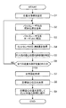
- FIG. 4 is a flowchart for explaining the calibration process of the target center-of-gravity position executed by the control unit 8 according to the first embodiment.
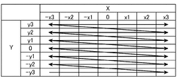
- FIG. 5 shows an example of the scanning level group set in step S1 of FIG.
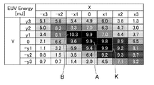
- FIG. 6 shows an example of an energy distribution diagram of the EUV light 277 created in step S7 of FIG.
- FIG. 7 shows an example of a distribution diagram of evaluation values in the X-axis coordinate component of the gravity center position of the EUV light 277 created in step S7 of FIG.
- FIG. 8 shows an example of a distribution diagram of evaluation values in the Y-axis coordinate component of the barycentric position of the EUV light 277 created in step S7 of FIG.
- the timing when the control unit 8 executes the calibration process of the target center-of-gravity position will be described later with reference to FIG.
- step S1 the control unit 8 sets a scanning level group.
- the control unit 8 controls the irradiation position adjusting unit 7 so that the irradiation position of the pulse laser beam 31 is scanned on the XY plane intersecting the plasma generation region R1.
- the control part 8 acquires the measurement result of the EUV light sensor 43 for every scanning.
- the Rayleigh length of the pulse laser beam 31 in the plasma generation region R1 is 100 ⁇ m or more and 1000 ⁇ m or less. For this reason, even if the irradiation position of the pulsed laser beam 31 is scanned in the Z-axis direction, the amount of change in each scan of the acquired measurement result can be small.
- the control unit 8 causes the irradiation position adjusting unit 7 to scan the irradiation position of the pulse laser beam 31 on the XY plane intersecting the plasma generation region R1.
- the XY plane is a plane perpendicular to the traveling direction of the pulse laser beam 31 traveling toward the plasma generation region R1.
- the control unit 8 When the irradiation position of the pulse laser beam 31 is scanned, the control unit 8 performs scanning according to a scanning level group including a plurality of scanning levels having different positions as shown in FIG. That is, each of the plurality of scanning levels included in the scanning level group is a position where the irradiation position of the pulse laser beam 31 is scanned.
- the arrows in FIG. 5 indicate the progression order of the scanning levels.
- the scanning level group is created using a table arranged in a matrix with the current irradiation position as the center.
- the plurality of scanning levels included in the scanning level group indicate a plurality of positions arranged along the X axis and the Y axis on the XY plane intersecting the plasma generation region R1.
- the scanning level group is determined by the scanning width R and the interval S.
- the scanning width R is each width in the direction along the X axis and Y axis of the scanning range indicated by the entire scanning level group.
- the interval S is a scanning interval of each of a plurality of scanning levels.
- the scanning width R is determined according to the irradiation diameter D of the pulse laser beam 31 in the plasma generation region R1.
- the irradiation diameter D is determined in advance by experiments or simulations. Alternatively, the irradiation diameter D may be estimated from the arrangement angle of the optical elements included in the laser beam condensing optical system 22 or the laser beam transmission optical system 33.
- the scanning width R is, for example, a length included in a range from (1/3) D to (2/3) D.
- the scanning width R is, for example, (2/3) D.
- the interval S is calculated from (R / N).
- N is the number of divisions when the scanning width R is divided into a plurality of scanning levels in the direction along the X axis and the Y axis. That is, when the number of divisions is N, the number of scanning levels in the X-axis and Y-axis directions is N + 1, respectively.
- the division number N is a natural number of 2 to 6, for example.
- the irradiation diameter D is, for example, 120 ⁇ m.
- the scanning width R is, for example, 80 ⁇ m when the irradiation diameter D is 120 ⁇ m.
- the division number N is 6, for example, as shown in FIG.
- the interval S is, for example, 13 ⁇ m when the scanning width R is 80 ⁇ m and the division number N is 6.
- the scanning width R may be determined according to the spot diameter of the pulse laser beam 31 that is the beam diameter at the beam waist portion of the pulse laser beam 31. In this case, the scanning width R is determined by replacing the irradiation diameter D described above with the spot diameter of the pulsed laser light 31.
- the control unit 8 may hold a plurality of scanning level groups in advance and read in accordance with the irradiation condition and the irradiation diameter D of the pulse laser beam 31. Alternatively, the control unit 8 may create a scanning level group according to the irradiation condition of the pulse laser beam 31 and the irradiation diameter D. Then, the control unit 8 sets the read scanning level group or the created scanning level group.
- step S2 the control unit 8 controls the irradiation position adjusting unit 7 so that the irradiation position of the pulse laser beam 31 is scanned according to the set scanning level group.
- step S3 the control unit 8 transmits a trigger signal to the laser device 3 to irradiate the target 27 with the pulse laser beam 31. EUV light 277 is generated.
- step S ⁇ b> 4 the control unit 8 acquires the measurement result of the EUV light sensor 43. Specifically, the control unit 8 performs statistical processing on the plurality of measurement values transmitted from the plurality of EUV light sensors 43a to 43c, and acquires the energy of the EUV light 277.
- the energy of the EUV light 277 may be an average value of a plurality of measurement values transmitted from each of the plurality of EUV light sensors 43a to 43c.
- the control unit 8 acquires the energy of the EUV light 277 as a measurement result of the EUV sensor 43 and stores it in association with the current scanning level. Note that the control unit 8 may acquire the variation in the energy of the EUV light 277 as the measurement result of the EUV sensor 43 in addition to the energy of the EUV light 277 alone.
- the variation in energy of the EUV light 277 may be 3 ⁇ , for example.
- step S ⁇ b> 5 the control unit 8 specifies the evaluation value of the gravity center position of the EUV light 277. Specifically, the control unit 8 calculates Formula 1 and Formula 2 from the measurement result of the EUV light sensor 43 acquired in Step S4. Then, the control unit 8 specifies the calculated value of Formula 1 as the evaluation value in the X-axis coordinate component of the gravity center position of the EUV light 277. The control unit 8 specifies the calculated value of Expression 2 as the evaluation value in the Y-axis coordinate component of the gravity center position of the EUV light 277. Then, the control unit 8 stores the calculated values of Equation 1 and Equation 2 specified as the evaluation value of the gravity center position of the EUV light 277 in association with the current scanning level.
- step S6 the control unit 8 determines whether or not all of the plurality of scanning levels included in the set scanning level group have been scanned. If all the scanning levels have not been scanned, the control unit 8 proceeds to step S2. On the other hand, if all the scanning levels have been scanned, the control unit 8 proceeds to step S7.
- step S7 the control unit 8 creates an energy distribution map of the EUV light 277 as shown in FIG. 6 based on the measurement result of the EUV light sensor 43 stored in association with each scanning level.
- the control unit 8 distributes the evaluation value in the X-axis coordinate component of the gravity center position of the EUV light 277 as shown in FIG. 7 based on the calculated value of Equation 1 stored in association with each scanning level.
- Create a diagram the control unit 8 distributes the evaluation value in the Y-axis coordinate component of the center of gravity position of the EUV light 277 as shown in FIG. 8 based on the calculated value of Equation 2 stored in association with each scanning level. Create a diagram.
- step S8 the control unit 8 determines a target center-of-gravity position based on each distribution chart created in step S7.
- the process in which the control unit 8 determines the target center-of-gravity position will be described later with reference to FIGS.
- step S9 the control unit 8 sets the target center of gravity position determined in step S8 as a new target center of gravity position. And the control part 8 transfers to EUV light gravity center control.
- the controller 8 sets the target irradiation position of the irradiation position of the pulse laser beam 31 so that the gravity center position of the EUV light 277 becomes a new target gravity center position.
- the control part 8 controls the irradiation position adjustment part 7 according to the set target irradiation position.
- control unit 8 specifies a deviation between the current irradiation position of the pulsed laser light 31 and the new target irradiation position of the pulsed laser light 31 according to the new target gravity center position. And the control part 8 specifies the deviation of the condensing position of the present pulsed laser beam 31 and the new target condensing position of the pulsed laser beam 31 according to a new target irradiation position. Then, the control unit 8 determines the adjustment amount of the irradiation position adjustment unit 7 such that there is no deviation in the condensing position of the pulse laser beam 31.
- control unit 8 holds in advance a table indicating a correspondence relationship between the deviation at the irradiation position of the pulse laser beam 31 and the adjustment amount of the irradiation position adjustment unit 7. And the control part 8 determines the adjustment amount of the irradiation position adjustment part 7 which eliminates the deviation in the irradiation position of the pulse laser beam 31 with reference to this table. Further, the control unit 8 may hold in advance a function in which the correspondence relationship between the deviation in the irradiation position of the pulse laser beam 31 and the adjustment amount of the irradiation position adjusting unit 7 is defined.
- control part 8 may determine the adjustment amount of the irradiation position adjustment part 7 which eliminates the deviation in the irradiation position of the pulse laser beam 31 by calculating this function. Then, the control unit 8 controls the irradiation position adjusting unit 7 according to the determined adjustment amount, and moves the condensing position of the pulse laser beam 31. Thereby, the control unit 8 can substantially match the irradiation position of the pulse laser beam 31 with the new target irradiation position, and can substantially match the gravity center position of the EUV light 277 with the new target gravity position. In this way, the control unit 8 can calibrate the target barycenter position each time the EUV light barycenter control is executed.
- FIG. 9 shows a plurality of scanning levels arranged along the X axis and the Y axis with the scanning level A shown in FIG. 6 as the center, and measurement of the EUV light sensor 43 stored in association with these scanning levels. Results are shown.
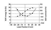
- FIG. 10 shows a plurality of scanning levels arranged along the X axis with the scanning level A shown in FIG. 6 as the center, and the X axis of the gravity center position of the EUV light 277 stored in association with these scanning levels. The evaluation value in a coordinate component is shown.
- FIG. 11 shows a plurality of scanning levels arranged along the Y axis with the scanning level A shown in FIG. 6 as the center, and the Y axis of the barycentric position of the EUV light 277 stored in association with these scanning levels.
- the evaluation value in a coordinate component is shown.
- FIG. 12 shows the energy distribution of the EUV light 277 and the distribution of evaluation values of the center of gravity in the direction along the X axis.
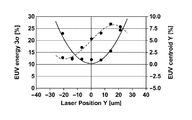
- FIG. 13 shows the energy distribution of the EUV light 277 in the direction along the Y-axis and the distribution of evaluation values of the center of gravity position.
- the control unit 8 determines the target center-of-gravity position by performing the following process based on the distribution map created in step S7 of FIG.
- the control unit 8 includes the EUV light among the measurement results of the EUV light sensor 43 acquired at each of a plurality of scanning levels included in the set scanning level group.
- a scanning level range K in which the energy of 277 is within a predetermined range is specified.
- the predetermined range is, for example, a range where the energy of the EUV light 277 is within the upper 10%.
- the control unit 8 calculates a weighted average value for each measurement result of the EUV light sensor 43 stored in association with each scanning level within the specified range K. Then, as shown in FIG. 6, the control unit 8 specifies the scanning level A at which the measurement result of the EUV light sensor 43 closest to the weighted average value is acquired.
- control unit 8 includes a plurality of scanning levels arranged along the X axis with the identified scanning level A as the center, and the Y axis with the identified scanning level A as the center. And a plurality of scanning levels arranged along the same line.
- the control unit 8 controls the X axis of the barycentric position of the EUV light 277 stored in association with a plurality of scanning levels arranged along the X axis with the scanning level A as the center.
- the evaluation value in the coordinate component is specified.
- the control unit 8 uses the Y axis of the barycentric position of the EUV light 277 stored in association with a plurality of scanning levels arranged along the Y axis with the scanning level A as the center.
- the evaluation value in the coordinate component is specified. Then, as indicated by the solid line in FIG.
- the control unit 8 determines the position of the center of gravity of the EUV light 277 in the direction along the X axis with the scanning level A as the center from the evaluation value specified as shown in FIG. Obtain the distribution of evaluation values. In addition, as shown by the solid line in FIG. 13, the control unit 8 determines the position of the center of gravity of the EUV light 277 in the direction along the Y axis from the evaluation value specified as shown in FIG. Find the distribution of evaluation values.
- Each distribution of the evaluation value of the gravity center position of the EUV light 277 changes linearly at the scanning level A and a position in the vicinity thereof as shown by the solid lines in FIGS. 12 and 13, and is separated from the scanning level A. Each position changes nonlinearly. A portion where the distribution of the evaluation value of the gravity center position of the EUV light 277 changes nonlinearly is considered to be an irradiation position where the irradiation position of the pulse laser beam 31 deviates from an appropriate position and a relatively large shooting deviation occurs. Therefore, the control unit 8 fits each distribution of evaluation values of the gravity center position of the EUV light 277 with a cubic function, as indicated by the broken lines in FIGS. 12 and 13.
- control part 8 determines the position corresponding to each inflection point in the cubic curve which each fitted cubic function shows as a target gravity center position. That is, the control unit 8 determines the position corresponding to the inflection point of the cubic curve indicated by the broken line in FIG. 12 as the X-axis coordinate component of the target gravity center position. The control unit 8 determines the position corresponding to the inflection point of the cubic curve indicated by the broken line in FIG. 13 as the Y-axis coordinate component of the target gravity center position. Or the control part 8 may fit each distribution of the evaluation value of the gravity center position of the EUV light 277 by a linear function, respectively.
- control part 8 may determine the position corresponding to each midpoint in the line segment which each fitted linear function shows as the X-axis and Y-axis coordinate component of a target gravity center position.
- control unit 8 may specify the maximum value and the minimum value in each distribution of the evaluation values of the gravity center position of the EUV light 277.
- control part 8 may determine the position corresponding to each average value in each specified maximum value and minimum value to the X-axis and Y-axis coordinate component of a target gravity center position.
- control unit 8 specifies the measurement result of the EUV light sensor 43 stored in association with a plurality of scanning levels arranged along the X axis with the scanning level A as the center. .
- control unit 8 specifies the measurement result of the EUV light sensor 43 stored in association with a plurality of scanning levels arranged along the Y axis with the scanning level A as the center. To do. Then, as indicated by the thick one-dot chain line in FIG. 12, the control unit 8 determines from the measurement result of the EUV light sensor 43 specified as in FIG. 9 in the direction along the X axis with the scanning level A as the center. The energy distribution of the EUV light 277 is obtained.
- control unit 8 determines from the measurement result of the EUV light sensor 43 specified as shown in FIG. 9 in the direction along the Y axis with the scanning level A as the center. The energy distribution of the EUV light 277 is obtained. Then, the control unit 8 fits each energy distribution of the EUV light 277 with a quadratic function or a Gaussian function, as indicated by the thin alternate long and short dash lines in FIGS. 12 and 13.
- the control unit 8 according to the first embodiment can calibrate the target barycentric position in the barycentric position of the EUV light 277 each time the EUV light barycentric control is executed. That is, the control unit 8 can calibrate the target center-of-gravity position to an optimum position in consideration of the measurement accuracy even if the measurement accuracy of the EUV light sensor 43 is not stable due to the influence of detection sensitivity or contamination. .
- the EUV light generation apparatus 1 of the first embodiment can constantly perform appropriate EUV light barycenter control, the irradiation position of the pulse laser light 31 can be controlled to an appropriate position.
- the EUV light generation apparatus 1 according to the first embodiment can suppress shooting deviation, it can suppress performance degradation of the EUV light 277.
- the EUV light generation apparatus 1 according to the second embodiment will be described with reference to FIGS. 6 to 8 and FIGS. 14 to 18.
- the EUV light generation apparatus 1 of the second embodiment has the same configuration as the EUV light generation apparatus 1 of the first embodiment.
- the EUV light generation apparatus 1 of the second embodiment is different from the EUV light generation apparatus 1 of the first embodiment in the operation of the control unit 8 related to the process of determining the target gravity center position at the gravity center position of the EUV light 277. .
- the description of the same configuration and operation as the EUV light generation apparatus 1 of the first embodiment is omitted.
- FIG. 14 shows a plurality of scanning levels arranged along the X axis and the Y axis with the scanning level B shown in FIG. 6 as the center, and the measurement of the EUV light sensor 43 stored in association with these scanning levels. Results are shown.
- 15 shows a plurality of scanning levels arranged along the X axis as the center of the scanning level B shown in FIG. 6, and the X-axis coordinates of the barycentric position of the EUV light 277 stored in association with these scanning levels.
- the evaluation value in a component is shown.
- 16 shows a plurality of scanning levels arranged along the Y axis with the scanning level B shown in FIG. 6 as the center, and the Y axis of the barycentric position of the EUV light 277 stored in association with these scanning levels.
- FIG. 17 shows the energy distribution of the EUV light 277 and the evaluation value distribution of the barycentric position in the direction along the X axis with the scanning level B as the center.
- FIG. 18 shows the energy distribution of the EUV light 277 and the evaluation value distribution of the barycentric position in the direction along the Y axis with the scanning level B as the center.
- the control unit 8 determines the target center-of-gravity position by performing the following process based on the distribution map created in step S7 of FIG.
- the control unit 8 includes the EUV light among the measurement results of the EUV light sensor 43 acquired at each of a plurality of scanning levels included in the set scanning level group.
- the scan level B with the maximum energy of 277 is specified.
- the control unit 8 includes a plurality of scanning levels arranged along the X axis with the identified scanning level B as the center, and the Y axis with the identified scanning level B as the center. And a plurality of scanning levels arranged along the same line.
- the control unit 8 controls the X axis of the barycentric position of the EUV light 277 stored in association with a plurality of scanning levels arranged along the X axis with the scanning level B as the center.
- the evaluation value in the coordinate component is specified.
- the control unit 8 uses the Y axis of the barycentric position of the EUV light 277 stored in association with a plurality of scanning levels arranged along the Y axis with the scanning level B as the center.
- the evaluation value in the coordinate component is specified. Then, as shown by the solid line in FIG.
- control unit 8 determines the position of the center of gravity of the EUV light 277 in the direction along the X axis from the evaluation value specified as shown in FIG. Obtain the distribution of evaluation values.
- control unit 8 determines the position of the center of gravity of the EUV light 277 in the direction along the Y axis with the scanning level B as the center from the evaluation value specified as shown in FIG. 16. Find the distribution of evaluation values.
- the control unit 8 converts each distribution of the evaluation values of the center of gravity position of the EUV light 277 into a third order as indicated by the broken lines in FIGS. 17 and 18. Fitting with function. And the control part 8 determines the position corresponding to each inflection point in the cubic curve which each fitted cubic function shows as a target gravity center position. Or the control part 8 may fit each distribution of the evaluation value of the gravity center position of the EUV light 277 by a linear function, respectively, similarly to the first embodiment. And the control part 8 may determine the position corresponding to each midpoint in the line segment which each fitted linear function shows as a target gravity center position.
- control part 8 may specify the maximum value and minimum value in each distribution of the evaluation value of the gravity center position of EUV light 277 similarly to 1st Embodiment. And the control part 8 may determine the position corresponding to each average value in each specified maximum value and minimum value as a target gravity center position.
- the EUV light generation apparatus 1 of the second embodiment calibrates the target centroid position of the EUV light 277 at the centroid position every time, and can constantly execute appropriate EUV light centroid control. As a result, the EUV light generation apparatus 1 according to the second embodiment can suppress the shooting deviation and suppress the performance deterioration of the EUV light 277 as in the first embodiment.
- the EUV light generation apparatus 1 according to the third embodiment will be described with reference to FIGS. 19 and 20.
- a plurality of pulse laser beams 31 are irradiated to one target 27 supplied to the plasma generation region R1.
- the laser device 3 according to the third embodiment has a different configuration from the laser device 3 according to the first or second embodiment.
- the EUV light generation apparatus 1 according to the third embodiment differs from the EUV light generation apparatus 1 according to the first or second embodiment in the configuration of the laser light transmission optical system 33 and the irradiation position adjustment unit 7 and is delayed.
- a circuit 81 is added.
- the EUV light generation apparatus 1 according to the third embodiment is different from the EUV light generation apparatus 1 according to the first or second embodiment in the operation of the control unit 8 related to the calibration process of the target gravity center position.
- the description of the same configuration and operation as the EUV light generation apparatus 1 of the first or second embodiment is omitted.
- FIG. 19 is a diagram for explaining a configuration of an EUV light generation system 11 including the EUV light generation apparatus 1 according to the third embodiment.
- the laser apparatus 3 according to the third embodiment outputs a plurality of pulsed laser beams to irradiate one target 27 supplied to the plasma generation region R1.
- the laser device 3 outputs, for example, three pulse laser beams of a first pre-pulse laser beam 31b, a second pre-pulse laser beam 31c, and a main pulse laser beam 31a in this order.
- the laser device 3 includes a main pulse laser device 3a, a first prepulse laser device 3b, and a second prepulse laser device 3c.
- the main pulse laser device 3a is a laser device 3 that outputs a main pulse laser beam 31a.
- the main pulse laser device 3a is a gas laser device such as a CO 2 laser device.
- the main pulse laser beam 31a is a laser beam applied to the target 27 in order to generate plasma 275 and generate EUV light 277.
- the first and second prepulse laser devices 3b and 3c are laser devices 3 that output first and second prepulse laser beams 31b and 31c, respectively.
- Each of the first and second prepulse laser devices 3b and 3c is a solid-state laser device such as a YAG laser device.
- Each of the first and second pre-pulse laser beams 31 b and 31 c is a laser beam irradiated on the target 27 before the main pulse laser beam 31 a is irradiated on the target 27.
- the wavelengths of the first and second prepulse laser beams 31b and 31c may be different from each other.
- the first prepulse laser beam 31b, the second prepulse laser beam 31c, and the main pulse laser beam 31a are also collectively referred to as a pulse laser beam 31.
- the laser light transmission optical system 33 includes a high reflection mirror 341, a mirror 342, a first mirror optical system 343, and a beam combiner 351.
- the high reflection mirror 341 is a mirror that reflects the main pulse laser beam 31 a output from the main pulse laser device 3 a toward the beam combiner 351.
- the mirror 342 is a mirror that reflects the first prepulse laser beam 31b output from the first prepulse laser apparatus 3b toward the beam combiner 351.
- the mirror 342 is a mirror that transmits the second prepulse laser beam 31 c reflected by the first mirror optical system 343 toward the beam combiner 351.
- the first mirror optical system 343 is an optical system that introduces the second prepulse laser beam 31c output from the second prepulse laser apparatus 3c into the beam combiner 351 along the optical path axis substantially the same as that of the first prepulse laser beam 31b.
- the first mirror optical system 343 is disposed on the optical path of the second pre-pulse laser beam 31c before entering the laser beam focusing optical system 22.
- the first mirror optical system 343 includes a high reflection mirror 344 and a stage 345.
- the high reflection mirror 344 is a mirror that reflects the second prepulse laser beam 31 c output from the second prepulse laser apparatus 3 c toward the beam combiner 351 via the mirror 342.
- the high reflection mirror 344 is mounted on the stage 345.
- the stage 345 is a mechanism that adjusts at least one of the position and posture of the high reflection mirror 344.
- the stage 345 is configured so that the optical path axis of the second prepulse laser beam 31c reflected by the high reflection mirror 344 is substantially the same as the optical path axis of the first prepulse laser beam 31b reflected by the mirror 342. It is a mechanism that adjusts the position and posture.
- the driving of the stage 345 is controlled by the control unit 8.
- the beam combiner 351 is an optical system that introduces the first and second pre-pulse laser beams 31 b and 31 c and the main pulse laser beam 31 a into the chamber 2 by being coupled to substantially the same optical path axis.
- the beam combiner 351 includes a dichroic mirror 352 and a second mirror optical system 353.
- the dichroic mirror 352 is a mirror that reflects the first prepulse laser beam 31 b reflected by the mirror 342 and the second prepulse laser beam 31 c transmitted through the mirror 342 toward the window 215.
- the dichroic mirror 352 is a mirror that transmits the main pulse laser beam 31 a reflected by the second mirror optical system 353 toward the window 215.
- the second mirror optical system 353 is configured to cause the main pulse laser beam 31a reflected by the high reflection mirror 341 to be chamber 2 with substantially the same optical path axis as the first and second prepulse laser beams 31b and 31c reflected by the dichroic mirror 352. It is an optical system to be introduced inside.
- the second mirror optical system 353 is disposed on the optical path of the main pulse laser beam 31a before entering the laser beam condensing optical system 22.
- the second mirror optical system 353 includes a high reflection mirror 354 and a stage 355.
- the high reflection mirror 354 is a mirror that reflects the main pulse laser beam 31 a reflected by the high reflection mirror 341 toward the window 215 via the dichroic mirror 352.
- the high reflection mirror 354 is mounted on the stage 355.
- the stage 355 is a mechanism that adjusts at least one of the position and posture of the high reflection mirror 354.
- the stage 355 is configured so that the optical path axis of the main pulse laser beam 31a reflected by the high reflection mirror 354 is substantially the same as the optical path axis of the first prepulse laser beam 31b reflected by the dichroic mirror 352. It is a mechanism that adjusts the position and posture.
- the driving of the stage 355 is controlled by the control unit 8.
- the irradiation position adjusting unit 7 according to the third embodiment is configured by using a laser beam condensing optical system 22 as in the first embodiment.
- the irradiation position adjusting unit 7 is configured using the first and second mirror optical systems 343 and 353.
- the irradiation position adjusting unit 7 is configured using the first and second mirror optical systems 343 and 353 and the laser beam condensing optical system 22.
- the delay circuit 81 is a circuit that adjusts the output timing of the pulsed laser light 31 from the laser device 3 in accordance with the delay time set by the control unit 8.
- the operation of the EUV light generation apparatus 1 according to the third embodiment will be described. First, the operations of the control unit 8 and the delay circuit 81 that control the operation of the laser device 3 according to the third embodiment will be described.
- the control unit 8 according to the third embodiment sets the delay times Td1 to Td3 in the delay circuit 81.
- the delay time Td1 is a time for making the timing at which the first pre-pulse laser beam 31b is focused on the plasma generation region R1 substantially coincide with the timing at which the target 27 is supplied to the plasma generation region R1.
- the delay time Td2 is a time for substantially matching the timing at which the second prepulse laser beam 31c is focused on the plasma generation region R1 with the timing at which the target 27 irradiated with the first prepulse laser beam 31b is appropriately diffused. is there.
- the delay time Td3 is a time for making the timing at which the main pulse laser beam 31a is focused on the plasma generation region R1 substantially coincide with the timing at which the target 27 irradiated with the second prepulse laser beam 31c is appropriately diffused. .
- the control unit 8 transmits the target detection signal generated at the passage timing of the target detection region R2 to the delay circuit 81 as it is.
- the delay circuit 81 transmits a first trigger signal that gives a trigger for outputting the first prepulse laser beam 31b to the first prepulse laser apparatus 3b at a timing delayed by a delay time Td1 from the timing at which the target detection signal is received. That is, the delay circuit 81 outputs the first prepulse laser beam 31b from the first prepulse laser apparatus 3b at a timing obtained by adding the delay time Td1 to the passing timing of the target detection region R2. Thereby, the first prepulse laser beam 31b output from the first prepulse laser apparatus 3b is irradiated to the target 27 supplied to the plasma generation region R1.
- the target 27 irradiated with the first prepulse laser beam 31b is in a state in which fine particles such as microdroplets and clusters are diffused in a mist form.
- the delay circuit 81 outputs the second prepulse laser beam 31c from the second prepulse laser apparatus 3c at a timing obtained by adding a delay time Td2 to the passing timing of the target detection region R2.
- the second prepulse laser beam 31c output from the second prepulse laser apparatus 3c is irradiated to the target 27 that is irradiated with the first prepulse laser beam 31b and appropriately diffused.
- the target 27 irradiated with the second pre-pulse laser beam 31 c is in a diffused state including finer particles and the vapor of the target 27.
- the target 27 irradiated with the second pre-pulse laser beam 31c may be in a state in which a part of the target 27 is turned into plasma and includes pre-plasma containing ions or neutral particles.
- the delay circuit 81 outputs the main pulse laser beam 31a from the main pulse laser device 3a at a timing obtained by adding a delay time Td3 to the passing timing of the target detection region R2.
- the main pulse laser beam 31a output from the main pulse laser device 3a is irradiated to the target 27 which is irradiated with the second pre-pulse laser beam 31c and appropriately diffused.
- the target 27 irradiated with the main pulse laser beam 31a is turned into plasma and emits radiation light 276 including EUV light 277.
- the irradiation efficiency of the main pulse laser beam 31a on the target 27 irradiated with the second pre-pulse laser beam 31c is higher than that of the main pulse laser beam 31a applied to the target 27 supplied to the plasma generation region R1. Can increase.
- FIG. 20 is a flowchart for explaining the calibration process of the target center-of-gravity position executed by the control unit 8 according to the third embodiment.
- step S11 the control unit 8 executes the same process as in step S1 shown in FIG.
- step S12 the control unit 8 controls the irradiation position adjusting unit 7 so that the irradiation positions of the first and second prepulses and the main pulse laser beams 31a to 31c are scanned according to the set scanning level group. Specifically, the control unit 8 controls the laser beam condensing optical system 22 so that the irradiation positions of the first and second pre-pulses and the main pulse laser beams 31a to 31c are scanned. At this time, the control unit 8 may control the first and second mirror optical systems 343 and 353 in addition to the laser beam condensing optical system 22.
- step S13 the control unit 8 transmits the first to third trigger signals to the first and second prepulses and the main pulse laser devices 3a to 3c, respectively, and the first and second prepulses and the main pulse laser beams 31a to 31c. Is irradiated to the target 27.
- Steps S14 to S19 the control unit 8 performs the same processing as Steps S4 to S9 shown in FIG.
- the EUV light generation apparatus 1 of the third embodiment even if the pulse laser light 31 is composed of a plurality of pulse laser lights, the target gravity center position at the gravity center position of the EUV light 277 is the same as in the first or second embodiment. Can be calibrated each time, and appropriate EUV light barycenter control can be performed constantly. As a result, the EUV light generation apparatus 1 according to the third embodiment can suppress shooting deviation and suppress the performance deterioration of the EUV light 277 as in the first or second embodiment.
- the EUV light generation apparatus 1 according to the fourth embodiment will be described with reference to FIG.
- the EUV light generation apparatus 1 according to the fourth embodiment has the same configuration as the EUV light generation apparatus 1 according to the first, second, or third embodiment.
- the EUV light generation apparatus 1 according to the fourth embodiment differs from the EUV light generation apparatus 1 according to the first, second, or third embodiment in the operation of the control unit 8 related to the calibration process of the target gravity center position.
- the description of the same configuration and operation as the EUV light generation apparatus 1 of the first, second, or third embodiment will be omitted.
- the control unit 8 according to the fourth embodiment performs EUV light barycenter control as in the first, second, or third embodiment.
- the control unit 8 according to the fourth embodiment executes calibration processing of the target center-of-gravity position when a predetermined event occurs. That is, the time when the control unit 8 executes the calibration process of the target center-of-gravity position is when a predetermined event occurs.
- the predetermined event means that the EUV light generation apparatus 1 is activated, that the EUV light 277 has been generated by a predetermined number of pulses, the performance of the EUV light 277 has deteriorated, and that the EUV light generation apparatus 1 has been activated. It is at least one of the events that the predetermined time has elapsed.
- the predetermined number of pulses is, for example, the number of pulses included in a range of 0.5 Bpls (Billion pulse) to 5 Bpls.
- the predetermined number of pulses is, for example, 0.5 Bpls.
- the predetermined time is, for example, one day.
- the performance of the EUV light 277 is at least one of the energy of the EUV light 277 and the energy variation of the EUV light 277 as described above.
- FIG. 21 is a flowchart for explaining the timing when the control unit 8 according to the fourth embodiment executes the calibration process of the target center-of-gravity position.
- the control unit 8 displays the two events when the EUV light generation apparatus 1 is activated and when the EUV light 277 is generated by a predetermined number of pulses. It is representatively shown that the target center-of-gravity position calibration process is executed.
- the control unit 8 performs the following processing when the EUV light generation apparatus 1 is activated.
- step S21 the control unit 8 notifies the exposure apparatus 9 that the calibration process of the target gravity center position is to be executed.
- step S ⁇ b> 22 the control unit 8 executes a target gravity center position calibration process.
- the control unit 8 scans the irradiation position of the pulsed laser light 31 according to a plurality of scanning levels whose positions are different from each other, and acquires the measurement result of the EUV light sensor 43 at each of the plurality of scanning levels.
- the control unit 8 specifies the evaluation value of the center of gravity position of the EUV light 277 at each of a plurality of scanning levels from the acquired measurement result of the EUV light sensor 43.
- the control unit 8 calibrates the target centroid position at the centroid position of the EUV light 277 based on the obtained measurement result of the EUV light sensor 43 and the identified evaluation value of the centroid position.
- step S23 the control unit 8 notifies the exposure apparatus 9 that the calibration process for the target center-of-gravity position has been completed.
- step S24 the control unit 8 counts the number of pulses of the generated EUV light 277.
- the control unit 8 counts the number of pulses of the EUV light 277 by counting the number of times the target detection signal is generated.
- the control unit 8 may count the number of pulses of the EUV light 277, for example, by counting the number of times the measurement result of the EUV light sensor 43 is acquired.
- step S25 the control unit 8 determines whether or not the EUV light 277 has been generated for a predetermined number of pulses.
- the predetermined number of pulses is, for example, the number of pulses included in a range of 0.5 Bpls (Billion pulses) to 5 Bpls.
- the predetermined number of pulses is, for example, 0.5 Bpls. If the EUV light 277 is not generated by the predetermined number of pulses, the control unit 8 proceeds to step S24. On the other hand, if the EUV light 277 is generated by the predetermined number of pulses, the control unit 8 proceeds to step S21.
- the control unit 8 can execute the calibration process of the target center-of-gravity position in the same way as in FIG. For example, when the target gravity center position calibration process is executed when the performance of the EUV light 277 is deteriorated, the control unit 8 may execute a process of acquiring the measurement result of the EUV light sensor 43 in step S24. . In step S25, the control unit 8 may perform a process of determining whether at least one of the energy of the EUV light 277 and the energy variation of the EUV light 277 is out of the allowable range.
- the control unit 8 starts from the time of activation of the EUV light generation apparatus 1 in step S24. What is necessary is just to perform the process which counts elapsed time. And the control part 8 should just perform the process which determines whether this elapsed time reached predetermined time in step S25.
- the EUV light generation apparatus 1 of the fourth embodiment calibrates the target center of gravity position at the center of gravity of the EUV light 277 each time, and constantly performs appropriate EUV light center of gravity control. Can run into. As a result, the EUV light generation apparatus 1 according to the fourth embodiment can suppress shooting deviation and suppress the performance deterioration of the EUV light 277 as in the first, second, or third embodiment.
- the EUV light generation apparatus 1 according to the fifth embodiment will be described with reference to FIGS. 22 to 31.
- the EUV light 277 emits burst light.
- a laser apparatus that can generate pulsed laser light 31 at a predetermined high frequency is used as the laser apparatus 3 shown in FIG. 1 in order to cause the EUV light 277 to emit light in bursts.
- the process for obtaining the center of gravity position of the EUV light 277 and the calibration process of the target center of gravity position are different from the processes in the first to fourth embodiments.
- the control unit 8 has a configuration capable of performing these different processes.
- the EUV light generation apparatus 1 of the fifth embodiment may be basically configured similarly to the EUV light generation apparatus 1 of the first embodiment.
- the target irradiation by the prepulse is performed. May be applied.
- FIG. 22 schematically shows the state of burst light emission performed in the EUV light generation apparatus 1 of the fifth embodiment and the sixth and seventh embodiments described later.
- each burst light emission period shown as “burst 1”, “burst 2”, “burst 3”,... Is repeated with a predetermined pause period in between.
- the vertical line of each burst emission period indicates the energy of the EUV light 277 shown in FIG. 1, for example. That is, in each burst light emission period, a group of EUV light 277 that emits pulses at a high frequency is output.
- control unit 8 is basically performed according to the flowchart shown in FIG. 4 as in the first embodiment, but the processing in several steps is performed in the first embodiment. Different from processing. In the following, this different processing will be mainly described.
- the target 27 is scanned with the pulse laser beam 31 so as to sequentially irradiate a plurality of scanning levels as shown in FIG.
- This pulse laser beam 31 is burst-oscillated at a predetermined high frequency in order to cause the EUV light 277 to emit light in bursts.
- a plurality of pulsed EUV lights 277 are emitted at one scanning level.
- step S4 the control unit 8 acquires the measurement result of the EUV light sensor 43. Specifically, the control unit 8 performs statistical processing on a plurality of measurement values transmitted from each of the plurality of EUV light sensors 43a to 43c, and acquires the energy of the plurality of EUV lights 277 for each scanning level. To do.
- the energy of one EUV light 277 emitted in a pulse shape may be an average value of a plurality of measurement values transmitted from each of the plurality of EUV light sensors 43a to 43c.
- the control unit 8 acquires an index indicating the energy variation of the plurality of EUV lights 277 based on the measurement result of the EUV sensor 43 in step S5. More specifically, this index is an index indicating energy variation for a plurality of pulsed EUV lights 277 at one scanning level. This index is, for example, EUV energy 3 ⁇ [%] described below.
- This EUV energy 3 ⁇ [%] is obtained as follows. For example, in one burst light emission period, the pulse laser beam 31 is oscillated 10,000 pulses. That is, in one burst, the EUV light 277 is emitted 10,000 times in a pulse shape.
- the control unit 8 obtains an average value of energy of the EUV light 277 that emits burst light and a standard deviation ⁇ for each scanning level. Then, the control unit 8 obtains a value of (3 ⁇ / average value) ⁇ 100 [%] of each burst from the average value and the standard deviation ⁇ , obtains an average value of 10 bursts of the value, and calculates EUV energy. 3 ⁇ [%].
- the control unit 8 stores the value of the EUV energy 3 ⁇ [%] in association with each scanning level.
- step S5 the control unit 8 specifies the evaluation value of the gravity center position of the EUV light 277.
- the evaluation value is specified by, for example, calculating Formula 1 and Formula 2, as in the first embodiment.
- the control unit 8 specifies the calculated value of Formula 1 as the evaluation value in the X-axis coordinate component of the gravity center position of the EUV light 277.
- the control unit 8 specifies the calculated value of Formula 2 as the evaluation value in the Y-axis coordinate component of the gravity center position of the EUV light 277.
- the control unit 8 stores the specified two evaluation values in association with each scanning level.
- step S6 the control unit 8 determines whether or not all of the plurality of scanning levels included in the set scanning level group have been scanned. If all the scanning levels have not been scanned, the control unit 8 proceeds to step S2 and continues the processing. On the other hand, if all the scanning levels have been scanned, the control unit 8 proceeds to step S7 and continues the process.
- step S7 the control unit 8 generates a distribution map of the values of EUV energy 3 ⁇ [%] as shown in FIG. 23 based on the values of EUV energy 3 ⁇ [%] stored in association with each scanning level. create. Further, the control unit 8 creates a distribution diagram as shown in FIG. 24 based on the calculated value of Equation 1 stored in association with each scanning level. This distribution diagram shows a distribution of evaluation values in the X-axis coordinate component of the gravity center position of the EUV light 277. In addition, the control unit 8 creates a distribution diagram as shown in FIG. 25 based on the calculated value of Formula 2 stored in association with each scanning level. This distribution diagram shows a distribution of evaluation values in the Y-axis coordinate component of the gravity center position of the EUV light 277.
- the values of ⁇ 21, ⁇ 14, ⁇ 7, 0, 7, 14, and 21 written together with X are X values from the reference position of a plurality of scanning levels arranged in the X-axis direction. Indicates the axial distance.
- the values of ⁇ 21, ⁇ 14, ⁇ 7, 0, 7, 14, and 21 written together with Y are Y values from the reference position of a plurality of scanning levels arranged in the Y-axis direction. Indicates the axial distance. The unit of these distances is ⁇ m. Further, the position of distance 0 is the reference position.
- step S8 the control unit 8 determines the target center-of-gravity position based on each distribution map created in step S7.
- the process in which the control unit 8 determines the target center-of-gravity position will be described later with reference to FIGS.
- step S9 by the control unit 8 is basically the same as the process in the first embodiment.
- FIG. 26 shows a plurality of scan levels arranged along the X axis and the Y axis with the scan level A shown in FIG. 23 as the center, and EUV energy 3 ⁇ [ %] Value.
- FIG. 27 shows a plurality of scanning levels arranged along the X axis with the scanning level A shown in FIG. 23 as the center, and the barycentric position of the EUV light 277 stored in association with each of these scanning levels. The evaluation value in an X-axis coordinate component is shown.
- FIG. 29 shows a distribution of values of EUV energy 3 ⁇ [%] in a direction along the X axis and a distribution of evaluation values of centroid positions. This evaluation value is a calculation result according to Equation 1 described above.
- FIG. 30 shows a distribution of values of EUV energy 3 ⁇ [%] in a direction along the Y-axis and a distribution of evaluation values of the center of gravity position. This evaluation value is a calculation result according to Equation 2 described above.
- the curve obtained by fitting the distribution of the EUV energy 3 ⁇ [%] value using a second-order polynomial approximation is indicated by a solid line
- the evaluation value distribution of the centroid position is indicated by a third-order degree. Curves fitted using the polynomial approximation are shown by broken lines.
- the control unit 8 determines the target center-of-gravity position by performing the following process based on the distribution map created in step S7 of FIG. That is, as shown in FIG. 23, the control unit 8 sets the scanning level at which the value of EUV energy 3 ⁇ [%] acquired at each of a plurality of scanning levels included in the set scanning level group is within a predetermined range.
- the range K is specified. This range K is, for example, a range where the value of EUV energy 3 ⁇ [%] is within the lower 10%. More specifically, the range K is a range in which the value of EUV energy 3 ⁇ [%] is not less than the minimum value and not more than 10% greater than the minimum value.
- the control unit 8 obtains the scanning level A shown in FIG. 23 based on the range K as follows. That is, the control unit 8 obtains a geometric center of gravity obtained by weighting the value of EUV energy 3 ⁇ [%] stored in association with each scanning level within the specified range K by the average value of the values, The scanning level closest to the geometric center of gravity is identified as scanning level A. Subsequently, as shown in FIG. 26, the control unit 8 has a plurality of scanning levels arranged along the X axis with the identified scanning level A as the center, and the Y axis with the identified scanning level A as the center. Identify a plurality of scan levels arranged along.
- control unit 8 stores the evaluation value of the center of gravity position of the EUV light 277 stored in association with a plurality of scanning levels arranged along the X axis with the scanning level A as the center. Is identified.
- control unit 8 evaluates the position of the center of gravity of the EUV light 277 stored in association with a plurality of scanning levels arranged along the Y axis with the scanning level A as the center. Identify the value.
- the control unit 8 obtains the distribution of evaluation values specified as shown in FIG. 27, that is, the distribution of evaluation values of the gravity center position of the EUV light 277 in the direction along the X axis with the scanning level A as the center.
- the control unit 8 fits this distribution using a third-order polynomial approximation.
- the cubic curve by this fitting is a curve indicated by a broken line in FIG.
- the control unit 8 obtains a distribution of values of EUV energy 3 ⁇ [%] in the direction along the X axis with the scanning level A as the center.
- the control unit 8 fits this distribution using a second-order polynomial approximation.
- the quadratic curve by this fitting is a curve indicated by a solid line in FIG.
- control unit 8 obtains the distribution of evaluation values specified as shown in FIG. 28, that is, the distribution of evaluation values of the center of gravity position of the EUV light 277 in the direction along the Y axis with the scanning level A as the center.
- the control unit 8 fits this distribution using a third-order polynomial approximation.
- the cubic curve by this fitting is a curve shown by the broken line in FIG. 30 as described above.
- the control unit 8 obtains a distribution of values of EUV energy 3 ⁇ [%] in the direction along the Y axis with the scanning level A as the center.
- the control unit 8 fits this distribution using a second-order polynomial approximation.
- the quadratic curve by this fitting is a curve indicated by a solid line in FIG.
- the distribution of evaluation values of the center of gravity position of the EUV light 277 changes linearly at the scanning level A and its neighboring positions as indicated by the broken lines in FIGS. 29 and 30, respectively, and at a position away from the scanning level A. Can vary non-linearly.
- the portion where the distribution of the evaluation values changes nonlinearly is considered to be an irradiation position where the irradiation position of the pulse laser beam 31 deviates from an appropriate position and a relatively large shooting deviation can occur.
- the control unit 8 determines the target center-of-gravity position based on each inflection point in the cubic curve indicated by each broken line in FIGS. In the present embodiment, the control unit 8 determines the target center-of-gravity position based not only on the inflection point but also on the distribution of the EUV energy 3 ⁇ [%] value.
- FIG. 31 is a diagram for explaining processing for determining the target center-of-gravity position. In FIG. 31, the cubic curve and the quadratic curve in FIG. 29 and FIG. 30 are schematically shown as broken lines and solid lines, respectively, as typical curves.
- the control unit 8 determines the target gravity center position as follows. That is, the control unit 8 obtains the EUV centroid position C center, s corresponding to the inflection point of the cubic curve shown in FIG. As the EUV centroid position C center, s , the midpoint of the maximum / minimum value of the EUV centroid measurement value may be selected, or the midpoint in the primary approximate measurement range may be selected. Further, the control unit 8 obtains the EUV centroid position C 3 ⁇ corresponding to the laser irradiation position as the apex from the quadratic curve shown in FIG. This EUV centroid position C 3 ⁇ is equivalent to the evaluation value of the centroid position corresponding to a point on the cubic curve at the laser irradiation position that is the apex.
- control part 8 calculates
- the control unit 8 performs the process for obtaining C target in, for example, step S8 in FIG.
- the process of obtaining C target from Equation 3 is performed based on the distribution of evaluation values of the center of gravity position in the X-axis direction and the distribution of EUV energy 3 ⁇ [%] values shown in FIG.
- the process for obtaining C target is similarly performed based on the distribution of evaluation values of the center of gravity position in the Y-axis direction and the distribution of values of EUV energy 3 ⁇ [%] shown in FIG.
- step S9 in FIG. 4 the control unit 8 sets the target center of gravity position determined in step S8 as a new target center of gravity position. And the control part 8 transfers to EUV light gravity center control.
- the controller 8 sets the target irradiation position of the irradiation position of the pulse laser beam 31 so that the gravity center position of the EUV light 277 becomes a new target gravity center position.
- the control part 8 controls the irradiation position adjustment part 7 according to the set target irradiation position.
- the control unit 8 specifies a deviation between the current irradiation position of the pulse laser light 31 and the new target irradiation position of the pulse laser light 31 according to the new target center of gravity position. And the control part 8 specifies the deviation of the condensing position of the present pulsed laser beam 31 and the new target condensing position of the pulsed laser beam 31 according to a new target irradiation position. Next, the control unit 8 determines the adjustment amount of the irradiation position adjusting unit 7 so that there is no deviation in the condensing position of the pulse laser beam 31. In this way, the control unit 8 can calibrate the target barycenter position each time the EUV light barycenter control is executed.
- the control unit 8 can calibrate the target barycentric position in the barycentric position of the EUV light 277 each time the EUV light barycentric control is executed.
- the operational effects obtained thereby are basically the same as the operational effects in the first embodiment.
- the target centroid is also considered in consideration of the value of the EUV centroid position C 3 ⁇ that is close to the minimum value of the EUV energy 3 ⁇ [%] that is an index indicating the variation of the plurality of EUV lights 277.
- the position is calibrated.
- the fact that the index is smaller means that a plurality of EUV lights 277 are emitted more stably. Therefore, if the target gravity center position is calibrated in consideration of the value of the EUV gravity center position C 3 ⁇ , the output of the EUV light 277 that emits burst light can be further stabilized.
- C target obtained from Equation 4 below is obtained as the target center-of-gravity position.
- the quadratic curve shown by the one-dot chain line in FIG. 32 is obtained by fitting the energy distribution of the EUV light 277 shown in FIG. 12 or FIG.
- the cubic curve indicated by a broken line in FIG. 32 is equivalent to the cubic curve indicated by a broken line in FIG.
- the EUV centroid position C center corresponds to the EUV centroid position C center, s in FIG.
- k center is set to 1, for example.
- the EUV light generation apparatus 1 of the sixth embodiment is different from the EUV light generation apparatus 1 of the fifth embodiment described above in the way of obtaining C target that is the target center-of-gravity position.
- the control unit 8 of the EUV light generation apparatus 1 according to the sixth embodiment may have a configuration for obtaining this different C target .
- a quadratic curve indicated by a one-dot chain line in FIG. 33 is a curve corresponding to a quadratic curve indicated by a one-dot chain line in FIG. Further, the cubic curve indicated by a broken line in FIG. 33 corresponds to the cubic curve indicated by a broken line in FIGS. 31 and 32. Further, the EUV centroid position C center, e shown in FIG. 33 is equivalent to the EUV centroid position C center, s shown in FIG. Also in this case, as the EUV centroid position C center, e , the midpoint of the maximum / minimum value of the EUV centroid measurement value may be selected, or the midpoint in the primary approximate measurement range may be selected.
- the control unit 8 obtains the quadratic curve by fitting the energy distribution of the EUV light 277.
- This energy distribution is obtained, for example, from the barycentric point of a value obtained by extracting a range within the upper 10% of the EUV light 277 energy.
- the energy of the EUV light 277 for example, an average value for 10 bursts of the EUV light 277 is applied.
- a distribution of emission efficiency of the EUV light may be used instead of the energy distribution of the EUV light 277.
- the emission efficiency of EUV light is the ratio of the energy of EUV light to the energy of laser light that irradiates the target.
- the control unit 8 obtains the EUV centroid position C energy based on the vertex from the quadratic curve obtained as described above. That is, the EUV center-of-gravity position C energy is a value taken by the cubic curve at the pulse laser irradiation position corresponding to the apex. And the control part 8 calculates
- the control unit 8 performs the process for obtaining C target in, for example, step S8 in FIG.
- the operational effects according to the sixth embodiment are basically the same as the operational effects according to the first embodiment.
- the target gravity center position is calibrated in consideration of the value of the EUV gravity center position C energy . Therefore, the EUV light 277 that emits burst light can have a higher output.
- the EUV light generation apparatus 1 according to the seventh embodiment differs from the EUV light generation apparatus 1 according to the fifth embodiment described above in how to obtain C target that is the target center-of-gravity position.
- the control unit 8 of the EUV light generation apparatus 1 according to the seventh embodiment may have a configuration for obtaining this different C target .
- a quadratic curve indicated by a one-dot chain line in FIG. 34 corresponds to a quadratic curve indicated by a one-dot chain line in FIGS. 32 and 33.
- a cubic curve indicated by a broken line in FIG. 34 corresponds to a cubic curve indicated by a broken line in FIGS.
- the quadratic curve indicated by the solid line in FIG. 34 corresponds to the quadratic curve indicated by the solid line in FIG.
- the EUV centroid positions C center, e and C energy shown in FIG. 34 are equivalent to the EUV centroid positions C center, e and C energy shown in FIG. 33, respectively.
- the EUV gravity center position C 3 ⁇ shown in FIG. 34 is equivalent to the EUV gravity center position C 3 ⁇ shown in FIG.
- the control unit 8 obtains C target obtained from Equation 6 below as the target center-of-gravity position.
- the control unit 8 performs the process for obtaining C target in, for example, step S8 in FIG.
- the operational effects of the seventh embodiment are basically the same as the operational effects of the first embodiment.
- the target centroid position is calibrated in consideration of the value of the EUV centroid position C 3 ⁇ and the value of the EUV centroid position C energy . Therefore, the output of the EUV light 277 that emits burst light is more stable and can be increased in output.
- Illumination optical system 420 Detection unit 421 ... Optical sensor 422 ...
- Light receiving optical system 43 EUV light sensor 43a ... EUV light sensor 43b EUV light sensor 43c EUV light sensor 7 ...
- Irradiation position adjuster 8 ... Control part 81 ...
- Delay circuit 9 Exposure apparatus A: Scanning level B: Scanning level IF ... Intermediate focusing point K ... range Q ... Target trajectory R1 ... Plasma generation region R2 ... Target detection area
Landscapes
- Physics & Mathematics (AREA)
- General Physics & Mathematics (AREA)
- Optics & Photonics (AREA)
- Spectroscopy & Molecular Physics (AREA)
- Engineering & Computer Science (AREA)
- Plasma & Fusion (AREA)
- Electromagnetism (AREA)
- Exposure And Positioning Against Photoresist Photosensitive Materials (AREA)
- X-Ray Techniques (AREA)
Abstract
L'invention concerne un générateur de lumière ultraviolette extrême qui comprend : une pluralité de capteurs de lumière ultraviolette extrême (EUV) pour mesurer l'énergie de la lumière EUV dans des directions différentes l'une de l'autre, ladite lumière EUV ayant été générée par exposition à un faisceau laser d'une cible apportée à une zone prescrite dans une chambre ; une unité de réglage de position d'incidence pour régler la position d'incidence du faisceau laser par rapport à la cible apportée à la zone prescrite ; et une unité de commande pour commander l'unité de réglage de position d'incidence de manière que le centroïde de la lumière EUV défini par les résultats de mesure de la pluralité de capteurs de lumière EUV devienne un centroïde cible. L'unité de commande commande l'unité de réglage de position d'incidence de manière que la position d'incidence décrive un balayage conformément à une pluralité de niveaux de balayage ayant des positions différentes l'une de l'autre, et étalonne le centroïde cible sur la base des résultats de mesure obtenus selon chaque niveau de balayage de la pluralité de niveaux de balayage.
Priority Applications (2)
| Application Number | Priority Date | Filing Date | Title |
|---|---|---|---|
| JP2018507379A JP6799583B2 (ja) | 2016-03-23 | 2017-03-22 | 極端紫外光生成装置及び極端紫外光の重心位置の制御方法 |
| US16/055,279 US10251254B2 (en) | 2016-03-23 | 2018-08-06 | Extreme ultraviolet light generating apparatus and control method for centroid of extreme ultraviolet light |
Applications Claiming Priority (2)
| Application Number | Priority Date | Filing Date | Title |
|---|---|---|---|
| PCT/JP2016/059236 WO2017163345A1 (fr) | 2016-03-23 | 2016-03-23 | Appareil de génération de lumière ultraviolette extrême, et procédé de commande de position de centre de gravité de lumière ultraviolette extrême |
| JPPCT/JP2016/059236 | 2016-03-23 |
Related Child Applications (1)
| Application Number | Title | Priority Date | Filing Date |
|---|---|---|---|
| US16/055,279 Continuation US10251254B2 (en) | 2016-03-23 | 2018-08-06 | Extreme ultraviolet light generating apparatus and control method for centroid of extreme ultraviolet light |
Publications (1)
| Publication Number | Publication Date |
|---|---|
| WO2017164251A1 true WO2017164251A1 (fr) | 2017-09-28 |
Family
ID=59900033
Family Applications (2)
| Application Number | Title | Priority Date | Filing Date |
|---|---|---|---|
| PCT/JP2016/059236 WO2017163345A1 (fr) | 2016-03-23 | 2016-03-23 | Appareil de génération de lumière ultraviolette extrême, et procédé de commande de position de centre de gravité de lumière ultraviolette extrême |
| PCT/JP2017/011516 WO2017164251A1 (fr) | 2016-03-23 | 2017-03-22 | Générateur de lumière ultraviolette extrême et procédé de commande de centroïde de lumière ultraviolette extrême |
Family Applications Before (1)
| Application Number | Title | Priority Date | Filing Date |
|---|---|---|---|
| PCT/JP2016/059236 WO2017163345A1 (fr) | 2016-03-23 | 2016-03-23 | Appareil de génération de lumière ultraviolette extrême, et procédé de commande de position de centre de gravité de lumière ultraviolette extrême |
Country Status (3)
| Country | Link |
|---|---|
| US (1) | US10251254B2 (fr) |
| JP (1) | JP6799583B2 (fr) |
| WO (2) | WO2017163345A1 (fr) |
Cited By (2)
| Publication number | Priority date | Publication date | Assignee | Title |
|---|---|---|---|---|
| JPWO2019175964A1 (ja) * | 2018-03-13 | 2021-03-18 | ギガフォトン株式会社 | 架台、極端紫外光生成システム、及びデバイスの製造方法 |
| JP2022007446A (ja) * | 2020-06-26 | 2022-01-13 | ギガフォトン株式会社 | 極端紫外光生成システム及び電子デバイスの製造方法 |
Families Citing this family (1)
| Publication number | Priority date | Publication date | Assignee | Title |
|---|---|---|---|---|
| JP7261683B2 (ja) * | 2019-07-23 | 2023-04-20 | ギガフォトン株式会社 | 極端紫外光生成システム及び電子デバイスの製造方法 |
Citations (4)
| Publication number | Priority date | Publication date | Assignee | Title |
|---|---|---|---|---|
| JP2007109451A (ja) * | 2005-10-12 | 2007-04-26 | Komatsu Ltd | 極端紫外光源装置の初期アライメント方法 |
| US8598552B1 (en) * | 2012-05-31 | 2013-12-03 | Cymer, Inc. | System and method to optimize extreme ultraviolet light generation |
| JP2014531743A (ja) * | 2011-08-19 | 2014-11-27 | エーエスエムエル ネザーランズ ビー.ブイ. | 光ビームアラインメントのためのエネルギセンサ |
| JP2015524599A (ja) * | 2012-07-06 | 2015-08-24 | イーティーエイチ・チューリッヒ | 液滴ターゲットとレーザとの間の相互作用を制御するための方法、および、前記方法を行なうための装置 |
Family Cites Families (1)
| Publication number | Priority date | Publication date | Assignee | Title |
|---|---|---|---|---|
| DE102014208792A1 (de) * | 2014-05-09 | 2015-11-12 | Carl Zeiss Smt Gmbh | System und Verfahren zur Analyse eines von einer Strahlführungsoptik geführten Lichtstrahls |
-
2016
- 2016-03-23 WO PCT/JP2016/059236 patent/WO2017163345A1/fr active Application Filing
-
2017
- 2017-03-22 JP JP2018507379A patent/JP6799583B2/ja active Active
- 2017-03-22 WO PCT/JP2017/011516 patent/WO2017164251A1/fr active Application Filing
-
2018
- 2018-08-06 US US16/055,279 patent/US10251254B2/en active Active
Patent Citations (4)
| Publication number | Priority date | Publication date | Assignee | Title |
|---|---|---|---|---|
| JP2007109451A (ja) * | 2005-10-12 | 2007-04-26 | Komatsu Ltd | 極端紫外光源装置の初期アライメント方法 |
| JP2014531743A (ja) * | 2011-08-19 | 2014-11-27 | エーエスエムエル ネザーランズ ビー.ブイ. | 光ビームアラインメントのためのエネルギセンサ |
| US8598552B1 (en) * | 2012-05-31 | 2013-12-03 | Cymer, Inc. | System and method to optimize extreme ultraviolet light generation |
| JP2015524599A (ja) * | 2012-07-06 | 2015-08-24 | イーティーエイチ・チューリッヒ | 液滴ターゲットとレーザとの間の相互作用を制御するための方法、および、前記方法を行なうための装置 |
Cited By (4)
| Publication number | Priority date | Publication date | Assignee | Title |
|---|---|---|---|---|
| JPWO2019175964A1 (ja) * | 2018-03-13 | 2021-03-18 | ギガフォトン株式会社 | 架台、極端紫外光生成システム、及びデバイスの製造方法 |
| JP7110323B2 (ja) | 2018-03-13 | 2022-08-01 | ギガフォトン株式会社 | 架台、極端紫外光生成システム、及びデバイスの製造方法 |
| JP2022007446A (ja) * | 2020-06-26 | 2022-01-13 | ギガフォトン株式会社 | 極端紫外光生成システム及び電子デバイスの製造方法 |
| JP7426299B2 (ja) | 2020-06-26 | 2024-02-01 | ギガフォトン株式会社 | 極端紫外光生成システム及び電子デバイスの製造方法 |
Also Published As
| Publication number | Publication date |
|---|---|
| JP6799583B2 (ja) | 2020-12-16 |
| US10251254B2 (en) | 2019-04-02 |
| WO2017163345A1 (fr) | 2017-09-28 |
| US20180343729A1 (en) | 2018-11-29 |
| JPWO2017164251A1 (ja) | 2019-02-14 |
Similar Documents
| Publication | Publication Date | Title |
|---|---|---|
| CN105723811B (zh) | 用于控制euv光源中的靶材料的微滴的系统和方法 | |
| US9241395B2 (en) | System and method for controlling droplet timing in an LPP EUV light source | |
| US8809823B1 (en) | System and method for controlling droplet timing and steering in an LPP EUV light source | |
| US10225918B2 (en) | Extreme ultraviolet light generating apparatus | |
| US9661730B2 (en) | Extreme ultraviolet light generation apparatus with a gas supply toward a trajectory of a target | |
| US10102938B2 (en) | Extreme ultraviolet light generating apparatus | |
| JP6775606B2 (ja) | 極端紫外光生成システム | |
| WO2017164251A1 (fr) | Générateur de lumière ultraviolette extrême et procédé de commande de centroïde de lumière ultraviolette extrême | |
| WO2016013114A1 (fr) | Appareil de génération de lumière ultraviolette extrême | |
| CN108348763B (zh) | 用于在lpp euv光源中控制源激光器激发的系统和方法 | |
| JP2014534559A (ja) | 放射源 | |
| US9510434B2 (en) | Extreme ultraviolet light generating apparatus, method of generating extreme ultraviolet light, concentrated pulsed laser light beam measuring apparatus, and method of measuring concentrated pulsed laser light beam | |
| WO2017130346A1 (fr) | Dispositif de génération de lumière ultraviolette extrême | |
| JP6378355B2 (ja) | 極端紫外光生成装置及び極端紫外光の生成方法 | |
| JP6866471B2 (ja) | Euv光生成装置 | |
| US20180173102A1 (en) | Extreme ultraviolet light generation device | |
| US9578730B2 (en) | Extreme ultraviolet light generation apparatus and extreme ultraviolet light generation system | |
| JP6556235B2 (ja) | 極端紫外光生成装置 | |
| JP2023048733A (ja) | Euv光生成装置、電子デバイス製造方法、及び検査方法 |
Legal Events
| Date | Code | Title | Description |
|---|---|---|---|
| WWE | Wipo information: entry into national phase |
Ref document number: 2018507379 Country of ref document: JP |
|
| NENP | Non-entry into the national phase |
Ref country code: DE |
|
| 121 | Ep: the epo has been informed by wipo that ep was designated in this application |
Ref document number: 17770291 Country of ref document: EP Kind code of ref document: A1 |
|
| 122 | Ep: pct application non-entry in european phase |
Ref document number: 17770291 Country of ref document: EP Kind code of ref document: A1 |