WO2017164094A1 - 変位拡大機構及びシャッタ装置 - Google Patents
変位拡大機構及びシャッタ装置 Download PDFInfo
- Publication number
- WO2017164094A1 WO2017164094A1 PCT/JP2017/010827 JP2017010827W WO2017164094A1 WO 2017164094 A1 WO2017164094 A1 WO 2017164094A1 JP 2017010827 W JP2017010827 W JP 2017010827W WO 2017164094 A1 WO2017164094 A1 WO 2017164094A1
- Authority
- WO
- WIPO (PCT)
- Prior art keywords
- actuator
- driven member
- driven
- displacement
- shutter device
- Prior art date
- Legal status (The legal status is an assumption and is not a legal conclusion. Google has not performed a legal analysis and makes no representation as to the accuracy of the status listed.)
- Ceased
Links
Images











Classifications
-
- B—PERFORMING OPERATIONS; TRANSPORTING
- B81—MICROSTRUCTURAL TECHNOLOGY
- B81B—MICROSTRUCTURAL DEVICES OR SYSTEMS, e.g. MICROMECHANICAL DEVICES
- B81B3/00—Devices comprising flexible or deformable elements, e.g. comprising elastic tongues or membranes
- B81B3/0035—Constitution or structural means for controlling the movement of the flexible or deformable elements
- B81B3/004—Angular deflection
- B81B3/0043—Increasing angular deflection
-
- B—PERFORMING OPERATIONS; TRANSPORTING
- B81—MICROSTRUCTURAL TECHNOLOGY
- B81B—MICROSTRUCTURAL DEVICES OR SYSTEMS, e.g. MICROMECHANICAL DEVICES
- B81B3/00—Devices comprising flexible or deformable elements, e.g. comprising elastic tongues or membranes
- B81B3/0035—Constitution or structural means for controlling the movement of the flexible or deformable elements
- B81B3/0037—For increasing stroke, i.e. achieve large displacement of actuated parts
-
- B—PERFORMING OPERATIONS; TRANSPORTING
- B81—MICROSTRUCTURAL TECHNOLOGY
- B81B—MICROSTRUCTURAL DEVICES OR SYSTEMS, e.g. MICROMECHANICAL DEVICES
- B81B3/00—Devices comprising flexible or deformable elements, e.g. comprising elastic tongues or membranes
- B81B3/0035—Constitution or structural means for controlling the movement of the flexible or deformable elements
- B81B3/0051—For defining the movement, i.e. structures that guide or limit the movement of an element
-
- B—PERFORMING OPERATIONS; TRANSPORTING
- B81—MICROSTRUCTURAL TECHNOLOGY
- B81B—MICROSTRUCTURAL DEVICES OR SYSTEMS, e.g. MICROMECHANICAL DEVICES
- B81B3/00—Devices comprising flexible or deformable elements, e.g. comprising elastic tongues or membranes
- B81B3/0064—Constitution or structural means for improving or controlling the physical properties of a device
- B81B3/0067—Mechanical properties
- B81B3/0072—For controlling internal stress or strain in moving or flexible elements, e.g. stress compensating layers
-
- G—PHYSICS
- G02—OPTICS
- G02B—OPTICAL ELEMENTS, SYSTEMS OR APPARATUS
- G02B26/00—Optical devices or arrangements for the control of light using movable or deformable optical elements
- G02B26/02—Optical devices or arrangements for the control of light using movable or deformable optical elements for controlling the intensity of light
-
- G—PHYSICS
- G02—OPTICS
- G02B—OPTICAL ELEMENTS, SYSTEMS OR APPARATUS
- G02B26/00—Optical devices or arrangements for the control of light using movable or deformable optical elements
- G02B26/02—Optical devices or arrangements for the control of light using movable or deformable optical elements for controlling the intensity of light
- G02B26/023—Optical devices or arrangements for the control of light using movable or deformable optical elements for controlling the intensity of light comprising movable attenuating elements, e.g. neutral density filters
-
- G—PHYSICS
- G03—PHOTOGRAPHY; CINEMATOGRAPHY; ANALOGOUS TECHNIQUES USING WAVES OTHER THAN OPTICAL WAVES; ELECTROGRAPHY; HOLOGRAPHY
- G03B—APPARATUS OR ARRANGEMENTS FOR TAKING PHOTOGRAPHS OR FOR PROJECTING OR VIEWING THEM; APPARATUS OR ARRANGEMENTS EMPLOYING ANALOGOUS TECHNIQUES USING WAVES OTHER THAN OPTICAL WAVES; ACCESSORIES THEREFOR
- G03B9/00—Exposure-making shutters; Diaphragms
- G03B9/08—Shutters
- G03B9/10—Blade or disc rotating or pivoting about axis normal to its plane
-
- B—PERFORMING OPERATIONS; TRANSPORTING
- B81—MICROSTRUCTURAL TECHNOLOGY
- B81B—MICROSTRUCTURAL DEVICES OR SYSTEMS, e.g. MICROMECHANICAL DEVICES
- B81B2201/00—Specific applications of microelectromechanical systems
- B81B2201/03—Microengines and actuators
- B81B2201/032—Bimorph and unimorph actuators, e.g. piezo and thermo
-
- B—PERFORMING OPERATIONS; TRANSPORTING
- B81—MICROSTRUCTURAL TECHNOLOGY
- B81B—MICROSTRUCTURAL DEVICES OR SYSTEMS, e.g. MICROMECHANICAL DEVICES
- B81B2201/00—Specific applications of microelectromechanical systems
- B81B2201/04—Optical MEMS
- B81B2201/045—Optical switches
-
- B—PERFORMING OPERATIONS; TRANSPORTING
- B81—MICROSTRUCTURAL TECHNOLOGY
- B81B—MICROSTRUCTURAL DEVICES OR SYSTEMS, e.g. MICROMECHANICAL DEVICES
- B81B2203/00—Basic microelectromechanical structures
- B81B2203/01—Suspended structures, i.e. structures allowing a movement
- B81B2203/0118—Cantilevers
-
- G—PHYSICS
- G03—PHOTOGRAPHY; CINEMATOGRAPHY; ANALOGOUS TECHNIQUES USING WAVES OTHER THAN OPTICAL WAVES; ELECTROGRAPHY; HOLOGRAPHY
- G03B—APPARATUS OR ARRANGEMENTS FOR TAKING PHOTOGRAPHS OR FOR PROJECTING OR VIEWING THEM; APPARATUS OR ARRANGEMENTS EMPLOYING ANALOGOUS TECHNIQUES USING WAVES OTHER THAN OPTICAL WAVES; ACCESSORIES THEREFOR
- G03B9/00—Exposure-making shutters; Diaphragms
- G03B9/08—Shutters
Definitions
- the technology disclosed herein relates to a displacement enlarging mechanism and a shutter device.
- the shutter device described in Patent Document 1 includes a displacement enlarging mechanism including a shutter and an actuator that drives the shutter.
- the actuator includes a beam and two side members, the beam extends from the base member, the end of the beam is folded back and connected to the first side member, and the end of the first side member is folded back to the second side. Connected to the side member, the end of the second side member is fixed.
- the shutter is attached to a connecting portion between the first side member and the second side member.
- the displacement magnifying mechanism when the beam is extended by heating, the first side member and the second side member are bent and the shutter is driven.
- the end of the second side member is fixed, so that the displacement of the shutter depends on the displacement of the beam connected to the first side member. Therefore, in order to drive the shutter with a larger swing width, the beam must be greatly expanded and contracted. However, there is a limit to the extension of the beam, and there is a problem that it cannot be extended so much. Further, if the beam is frequently expanded and contracted, a load accompanying deformation is accumulated in the beam, and in the worst case, the beam may be damaged.
- An object of the present invention is to provide a shutter device including an enlargement mechanism.
- the displacement enlarging mechanism disclosed herein includes a fixed portion, a first actuator and a second actuator coupled to the fixed portion, a first end portion and a second end portion, and the first end portion is A first beam coupled to the first actuator; a second end having a third end and a fourth end; wherein the third end is coupled to the second actuator; and the first beam A driven member connected to the second end and the fourth end of the second beam, the first beam and the second beam having a parallel arrangement portion arranged in parallel with each other;
- the driven member is coupled in the parallel arrangement portion, and the first actuator drives the first beam so as to be pulled in the extending direction of the first beam from the second end side, and the second actuator The actuator moves the second beam to the fourth end side. Driven to push the extending direction of Luo said second beam.
- the first actuator and the second actuator are connected to the fixed portion, the first end of the first beam is connected to the first actuator, and the third end of the second beam is the first end. 2 connected to the actuator, the driven member is connected to the second end of the first beam and the fourth end of the second beam, and the first beam and the second beam are arranged in parallel to each other.
- the driven member is connected to the parallel arrangement portion.
- the first actuator is driven to pull the first beam from the second end side in the extending direction of the first beam
- the second actuator is extended from the fourth end side to the second beam. Drive to push in the direction. That is, the driving force of the first beam and the second beam respectively driven by the first actuator and the second actuator is added to drive the driven member.
- the shutter device disclosed herein is disposed on the displacement magnifying mechanism and the fixed portion of the displacement magnifying mechanism, and the first end of the first actuator and the second actuator of the displacement magnifying mechanism.
- a first electrode that is electrically connected to the first end of the displacement enlarging mechanism, a second end of the first actuator of the displacement enlarging mechanism, and the second actuator.
- a second electrode electrically connected to the second end of the optical path, and the optical path is blocked and opened by the driven member of the displacement magnifying mechanism.
- the driven member can be greatly displaced by a slight displacement of the first actuator and the second actuator which are the driving members. Further, according to the shutter device provided with such a displacement enlarging mechanism, the driven member can be largely displaced by applying a low voltage between the first electrode and the second electrode.
- FIG. 2 is a cross-sectional view of the shutter device taken along line II-II in FIG.
- FIG. 6 is an enlarged plan view of a connecting portion between a first beam and a second beam and a driven member.
- FIG. 4 is a cross-sectional view of the shutter device taken along line IV-IV in FIG. 3.
- It is a top view of the shutter apparatus of a drive state. It is a figure which shows the manufacturing process of a shutter apparatus.
- 10 is a plan view of a shutter device according to Modification Example 1.
- FIG. 12 is a plan view of a shutter device according to Modification 2.
- FIG. 10 is a plan view of a shutter device according to Modification 3.
- FIG. 10 is a plan view of a shutter device according to Modification 3.
- FIG. 10 is a plan view of a shutter device according to Modification Example 5.
- FIG. 12 is a plan view of a shutter device according to Modification 6.
- FIG. 12 is a plan view of a shutter device according to Modification Example 7.
- FIG. It is a top view of the shutter apparatus which concerns on the modification 8.
- 12 is a plan view of a shutter device according to Modification Example 10.
- FIG. 14 is a plan view of a shutter device according to Modification 11.
- FIG. FIG. 16 is a plan view of a shutter device according to Modification 12. It is a top view at the time of the drive of the shutter apparatus shown to FIG. 18A.
- FIG. 14 is a cross-sectional view of a driven member according to Modification Example 13.
- FIG. 14 is another cross-sectional view of a driven member according to Modification Example 13.
- FIG. It is a top view of the shutter device concerning another embodiment of the present invention. It is a top view of the shutter apparatus which abbreviate
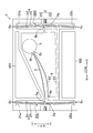
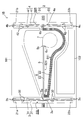
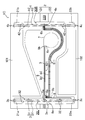
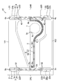
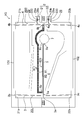
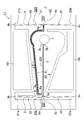
- FIG. 1 is a plan view of a shutter device 1 according to an embodiment of the present invention
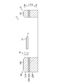
- FIG. 2 is a cross-sectional view of the shutter device 1 taken along line II-II in FIG.
- the inventors provide the accompanying drawings and the following description in order for those skilled in the art to fully understand the present invention, and these are intended to limit the subject matter described in the claims. is not.
- the dimensions, thicknesses, detailed shapes of details, and the like of each member depicted in the drawings may be different from actual ones.
- the shutter device 1 includes a fixed portion 2, a first actuator 3 and a second actuator 4 connected to the fixed portion 2, a first end portion 5a, and a second end portion 5b.
- the first end portion 5a is the first end portion 5a.
- a first beam 5 coupled to one actuator 3, a second beam 6 having a third end 6 b and a fourth end 6 c, the third end 6 b coupled to the second actuator 4, and a first A driven member 7 connected to the second end 5 b of the beam 5 and the fourth end 6 c of the second beam 6, a first electrode 101, and a second electrode 102 are provided.
- the longitudinal direction of the first beam 5 is referred to as the X direction
- the longitudinal directions of the first actuator 3 and the second actuator 4 are referred to as the Y direction
- the thickness direction of the shutter device 1 is referred to as the Z direction.
- the left side in FIG. 1 may be simply referred to as the left side
- the upper side in FIG. 1 may be simply referred to as the upper side
- the upper side in FIG. 2 may be referred to as the upper surface
- the first end 5a of the first beam 5 and the third end 6b of the second beam 6 are the base end
- the second end 5b of the first beam 5 and the fourth end 6c of the second beam 6 are the front end.
- the shutter device 1 is a so-called MEMS (Micro ElectroMechanical Systems) shutter, and is manufactured by a micromachining technique to which a semiconductor fine processing technique is applied.
- the shutter device 1 is manufactured using an SOI (Silicon on Insulator) substrate 200.
- the SOI substrate 200 includes a first silicon layer 210 made of single crystal silicon, an oxide film layer 220 made of SiO 2 , and a second silicon layer 230 made of single crystal silicon in this order. Configured.
- the fixed portion 2, the first actuator 3, the second actuator 4, the first beam 5, the second beam 6, and the driven member 7 are integrally formed of a silicon material, and the displacement expansion mechanism Is configured.
- the oxide film layer 220 and the second silicon layer 230 are left only on the lower surfaces of the first base member 21 and the second base member 22 constituting the fixed portion 2, and the first actuator 3 and the second actuator 4 which are movable members.
- the first beam 5, the second beam 6, and the oxide film layer 220 and the second silicon layer 230 on the lower surface of the driven member 7 are removed in the manufacturing process.
- the shutter device 1 has an overall rectangular shape in plan view.
- the fixing portion 2 is a frame that forms the overall shape of the shutter device 1 having such a rectangular shape in plan view.
- the fixed portion 2 includes a first base member 21 and a second base member 22 that are arranged to face each other in the Y direction.
- the upper side in the Y direction of the shutter device 1 is the first side
- the lower side in the Y direction opposite to the second side is the second side
- the left side in the X direction is the third side
- the X direction is opposite to it.
- the first base member 21 is formed of the first side, a part of the third side, and a part of the fourth side.
- the second base member 22 is formed of the second side, another part of the third side, and another part of the fourth side.
- Each of the first base member 21 and the second base member 22 has as large an area as possible while ensuring a movable range of the first actuator 3, the second actuator 4, the first beam 5, the second beam 6, and the driven member 7. The shape that occupies.
- the fixing portion 2 is divided into two parts, the first base member 21 and the second base member 22 in the first silicon layer 210, but is connected to one in the oxide film layer 220 and the second silicon layer 230. Yes. For this reason, the relative positions of the first base member 21 and the second base member 22 are fixed, and the movable member can be supported by the first base member 21 and the second base member 22.
- 1st base member 21 has the 1st crevice 21a and the 2nd crevice 21b opened towards the 2nd base member 22 which counters.
- the first recess 21 a is disposed at the left end of the first base member 21 in the X direction.
- the second recess 21 b is disposed at the right end of the first base member 21 in the X direction.
- the 2nd base member 22 has the 3rd crevice 22a and the 4th crevice 22b opened toward the 1st base member 21 which counters.
- the third recess 22 a is disposed at the left end of the second base member 22 in the X direction.
- the fourth recess 22 b is disposed at the right end of the second base member 22 in the X direction.
- first concave portion 21a of the first base member 21 and the third concave portion 22a of the second base member 22 are arranged at positions where the openings face each other, and are roughly rectangular in the Y direction for arranging the first actuator 3.
- the opening 20L is formed.
- the second concave portion 21b of the first base member 21 and the fourth concave portion 22b of the second base member 22 are arranged at positions where the openings face each other, and are roughly long in the Y direction for arranging the second actuator 4.
- a rectangular opening 20R is formed.
- portions other than the openings 20L and 20R are occupied by a pattern having a relatively large area.
- an opening 20L is formed along the third side on the left side in the X direction of the fixed part 2 formed in a substantially rectangular shape, and the fourth on the right side in the X direction of the fixed part 2 facing the first side.
- An opening 20R is formed along the side, and the first actuator 3 and the second actuator 4 are provided to face the opening 20L and the opening 20R facing each other.
- the fixed portion 2 has a shape that occupies as large an area as possible while ensuring the movable range of the movable member, and is thus required as a frame that supports the first actuator 3 and the second actuator 4. Ensures rigidity.
- the first actuator 3 includes two actuators 31 and 31 arranged in parallel.
- the two actuators 31, 31 are rod-shaped members extending in the Y direction, and are connected to each other at an intermediate portion 3 a at a substantially center in the longitudinal direction from the first end 3 b to the second end 3 c of the first actuator 3. ing.
- the driving forces of the two actuators 31 and 31 are combined and the first actuator 3 can exert a large driving force.
- the first actuator 3 is thermally expanded by heating by energization to generate a driving force.
- the first end portions 3 b and 3 b of the two actuators 31 and 31 are connected to the first base member 21 at the bottom surface portion of the first recess 21 a of the first base member 21.
- the second end portions 3 c and 3 c of the two actuators 31 and 31 are connected to the second base member 22 at the bottom surface portion of the third recess 22 a of the second base member 22.
- the first actuator 3 does not extend in a straight line in the Y direction, but is slightly bent so that the intermediate portion 3a protrudes to the left in the X direction, which is the driving direction, or entirely in the X direction. It is slightly curved so that it swells to the left.
- the second actuator 4 includes two actuators 41 and 41 arranged in parallel.
- the two actuators 41, 41 are rod-shaped members extending in the Y direction, and are connected to each other at an intermediate portion 4a at a substantially central portion in the longitudinal direction from the first end 4b to the second end 4c of the second actuator 4. ing.
- the driving forces of the two actuators 41 and 41 are combined and the second actuator 4 can exert a large driving force.
- the second actuator 4 is thermally expanded by heating by energization to generate a driving force.
- the first ends 4 b and 4 b of the two actuators 41 and 41 are connected to the first base member 21 at the bottom surface portion of the second recess 21 b of the first base member 21.
- the second ends 4 c and 4 c of the two actuators 41 and 41 are connected to the second base member 22 at the bottom surface portion of the fourth recess 22 b of the second base member 22.
- the second actuator 4 does not extend in a straight line in the Y direction, but is slightly bent so that the intermediate portion 4a protrudes to the right in the X direction that is the driving direction, or entirely in the X direction. It is slightly curved so that it swells to the right. Further, as described above, since the first actuator 3 and the second actuator 4 are bent or curved with respect to the driving direction, the first actuator 3 and the second actuator 4 are driven in the driving direction during thermal expansion due to heating. There is no bending or bending to the opposite side. Therefore, the first actuator 3 and the second actuator 4 can be reliably bent or curved toward the driving direction.
- the first actuator 3 is disposed on the left side in the X direction in the shutter device 1
- the second actuator 4 is disposed on the right side in the X direction in the shutter device 1
- the first actuator 3 and the second actuator 4 are viewed in plan view. Opposite.
- a driven member 7 is disposed between the first actuator 3 and the second actuator 4 facing each other. More specifically, the driven member 7 is disposed at a position near the second actuator 4. In the shutter device 1, the driven member 7 functions as a shutter that blocks and opens an optical path (not shown). Therefore, the driven member 7 is formed in a planar shape that is slightly larger than the cross section of the optical path, specifically in a circular shape.
- the driven member 7 is formed thinner than the other members constituting the displacement enlarging mechanism. Thereby, the mass of the driven member 7 is reduced and the resonance frequency is increased.
- a metal film 71 for example, an Au / Ti film is formed on the entire surface of the driven member 7.
- FIG. 3 is an enlarged plan view of a connecting portion between the first beam 5 and the second beam 6 and the driven member 7, and
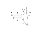
- FIG. 4 is a cross-sectional view of the shutter device 1 taken along line IV-IV in FIG.
- a heat radiating portion 72 is formed at the connecting portion between the first beam 5 and the second beam 6 and the driven member 7.
- the heat radiating portion 72 is formed using the difference between the thickness of the first beam 5 and the second beam 6 and the thickness of the driven member 7, and has a surface that stands upright from the surface of the driven member 7, for example.
- the surface is generated by the first actuator 3 when the first actuator 3 is driven and is transmitted from the first actuator 3 via the first beam 5 and / or the second actuator 4. It serves as a heat radiating surface for radiating heat generated by the second actuator 4 during driving and transmitted from the second actuator 4 via the second beam 6.
- the heat radiating portion 72 is connected to the driven member 7.
- the shape may be formed along the periphery and slightly larger than the driven member 7.
- a metal film such as gold may be formed on the surface of the driven member 7 as a blocking film for blocking light from a light source (not shown). It is possible to prevent silicon from diffusing into the metal film due to the temperature rise, and to prevent changes in optical characteristics such as inability to block light.
- the driven member 7 has a region where the thickness of the driven member 7 changes stepwise from the first beam 5 and the second beam 6, and the region may be the heat radiating part 72.
- the first beam 5, the second beam 6, the driven member 7, their boundaries, and other members may be used, and the shape of the heat dissipation portion 72 is not limited. Further, by making the driven member 7 thinner than the first beam 5 and the second beam 6, it is possible to reduce the inflow path of the heat propagated from the first beam 5 or the second member 62 of the second beam. The heat generated in the first actuator 3 and the second actuator 4 can be prevented from propagating to the driven member 7. Thereby, for example, in the driven member 7, it is possible to prevent silicon from diffusing into the metal film 71 and to prevent changes in optical characteristics such as inability to block light.
- the first beam 5 is a rod-shaped member extending in the X direction.
- the first end 5 a of the first beam 5 is connected to the intermediate portion 3 a of the first actuator 3.
- the second end 5 b of the first beam 5 is connected to the driven member 7.
- the second beam 6 is a member having a folded structure, and includes a first member 61 extending from the intermediate portion 4a of the second actuator 4 to the vicinity of the intermediate portion 3a of the first actuator 3, and an end portion 6a of the first member 61. And a second member 62 folded back toward the second actuator 4.
- the third end 6 b of the second beam 6 (that is, the tip on the first member 61 side) is connected to the intermediate portion 4 a of the second actuator 4.
- the fourth end 6 c of the second beam 6 (that is, the tip on the second member 62 side) is connected to the driven member 7.
- the second member 62 is a rod-shaped member that extends in the X direction from the end portion 6 a of the first member 61 and has the same thinness as the first beam 5.
- the second member 62 is arranged in parallel with the first beam 5 slightly below the first beam 5 in the Y direction.
- “the first beam 5 and the second member 62 of the second beam are arranged in parallel” means that the first beam 5 and the second member 62 of the second beam. Is arranged in a substantially parallel relationship.
- the portion 56 where the first beam 5 and the second member 62 of the second beam 6 are arranged in parallel with each other may be referred to as a parallel arrangement portion 56.
- first beam 5 and the second member 62 of the second beam 6 are connected in parallel to the driven member 7 from the same direction.
- the front end side of the first beam 5 is folded back by the heat radiating portion 72, so that the first beam 5 and the second beam 6 are connected at the connection portion between the first beam 5 and the second beam 6 and the driven member 7.
- the second member 62 is arranged in parallel.
- the front end side of the second member 62 of the second beam 6 is folded back by the heat radiating portion 72, so that the first beam 5 and the second beam 6 and the driven member 7 are connected at the first beam. 5 and the second member 62 of the second beam 6 are arranged in parallel.
- the first beam 5 pulls the driven member 7 from the second end 5b in the extending direction of the first beam 5, while the second beam 6 is driven in the extending direction of the second beam 6 from the fourth end 6c.
- the driven member 7 is driven by pushing the member 7.
- the second member 62 of the first beam 5 and the second beam 6 is driven by the first actuator 3 and the second actuator 4 to be elastically deformed to move the driven member 7 to another position on the XY plane. Move to.
- the first beam 5 may push the driven member 7 while the second beam 6 may pull the driven member 7.
- the first member 61 is a member having, for example, a bowl shape that bypasses the driven member 7. A part of the first member 61 extends so as to partition a part of the opening 20L where the first actuator 3 is formed and a part of the opening 20R where the second actuator 4 is formed. Further, the first member 61 has a high elastic region at least in part so as to have a higher elastic modulus than the second member 62, and is formed wider, for example. The first member 61 corresponds to a high elasticity region referred to in the claims. As will be described later, even when the second beam 6 is driven by the second actuator 4, the first member 61 is hardly elastically deformed and remains in a bowl shape, and the driving force of the second actuator 4 is increased by the second member 62.
- a part of the first member 61 may be thicker than the second member 62, or a metal film may be formed on a part of the first member 61.
- the second actuator 4 of the present embodiment may be eliminated, and the second beam 6 may be directly connected to the fixed portion 2.
- the second beam 6 is configured only by the second member 62, and The end of the second member 62 opposite to the fourth end 6c may be directly connected to the fixed portion 2 (the first base member 21 or the second base member 22).
- the second member 62 may be directly connected to the fixing portion 2 in a substantially straight line state or a slight curvature, or on the opposite side to the fourth end portion 6c of the second member 62. After the vicinity of the end portion thereof is bent, it may be connected to the fixing portion 2.
- the first electrode 101 is a metal film formed on the upper surface of the first base member 21, for example, an Au / Ti film.
- the second electrode 102 is a metal film formed on the upper surface of the second base member 22, for example, an Au / Ti film.
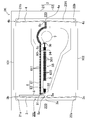
- FIG. 5 is a plan view of the shutter device 1 in a driving state.
- the shutter device 1 is driven by applying a voltage between the first electrode 101 and the second electrode 102.
- a voltage is applied between the first electrode 101 and the second electrode 102, a current flows to the first actuator 3 and the second actuator 4 through the first base member 21 and the second base member 22.
- Joule heat is generated in the first actuator 3 and the second actuator 4 made of silicon material, and the first actuator 3 and the second actuator 4 are heated to 400 to 500 ° C. in an instant.
- the first actuator 3 is thermally expanded so as to extend its entire length when heated. Since the first end portion 3b and the second end portion 3c of the first actuator 3 are fixed in position by the fixing portion 2 and cannot move, the intermediate portion 3a protrudes in advance due to the thermal expansion of the first actuator 3. Is pushed to the left in the X direction.
- the second actuator 4 is also thermally expanded so that its entire length is extended by being heated. Since the positions of the first end 4b and the second end 4c of the second actuator 4 are fixed by the fixing portion 2 and cannot move, the intermediate portion 4a protrudes in advance due to the thermal expansion of the second actuator 4. Is pushed to the right in the X direction.
- the intermediate portion 3a of the first actuator 3 When the intermediate portion 3a of the first actuator 3 is pushed to the left in the X direction, the first beam 5 connected thereto is pulled to the left in the X direction as a whole. Further, when the intermediate portion 4a of the second actuator 4 is pushed out to the right in the X direction, the second beam 6 connected thereto is pulled entirely to the right in the X direction.
- the relative positions of the first end 5a of the first beam 5 and the second end 6b of the second beam 6 change in a direction away from each other.
- the second end portion 5b of the first beam 5 and the fourth end portion 6c of the second beam 6 are driven obliquely upward to the left on the XY plane, and the second members of the first beam 5 and the second beam 6 are driven.
- 62 is greatly bent or bent with different curvatures, and the fourth end 6 c of the second beam 6 pushes the driven member 7, while the second end 5 b of the first beam 5 pulls the driven member 7.
- the first member 61 of the second beam 6 is slightly rotated counterclockwise on the XY plane about the third end 6b, and the driven member 7 is positioned on the XY plane as shown in FIG. Pushed out.
- the second actuator 4 is configured by connecting a plurality of actuators, so that the first of the second beam 6 can be compared with the case where the second actuator 4 is configured by one actuator.
- the member 61 can increase counterclockwise rotational rigidity on the XY plane with the third end 6b as an axis.
- the relative positions of the first end 5a of the first beam 5 and the second end 6b of the second beam 6 change in a direction approaching each other.
- the second end portion 5b of the first beam 5 and the fourth end portion 6c of the second beam 6 are pushed back diagonally downward to the right on the XY plane, and the first and second beams 5 and 2 that have been bent or bent are bent.
- the second member 62 of the beam 6 returns to the original substantially linear shape, and the first member 61 of the second beam 6 slightly rotates clockwise on the XY plane about the third end 6b to return to the original position.
- the driven member 7 returns to the position on the XY plane as shown in FIG.
- the position of the driven member 7 on the XY plane is changed by switching the voltage application (the driving state of the shutter device 1) and the release (the driven state of the shutter device 1) to the electrodes 101 and 102. 5 and switching as shown in FIG.
- An optical path (not shown) is arranged so as to overlap the driven member 7 shown in FIG. 1 or the driven member 7 shown in FIG. 5, and the position of the driven member 7 is as shown in FIGS.
- the driven member 7 functions as a shutter that blocks and opens an optical path (not shown).
- the optical path (not shown) may be blocked at a position where the driven member 7 is not driven by the first actuator 3 and the second actuator 4, and the optical path may be opened at the driven position. 7 is not driven by the first actuator 3 and the second actuator 4, and an optical path (not shown) may be opened, and the optical path may be blocked at the driven position.
- the configuration of the thermal drive type actuator that drives the driven member 7 by the thermal expansion of the constituent members is exemplified.
- the first beam 5 and the second beam 6 may be heated as long as they are driven as described above.
- a method other than the driving method for example, a capacitance driving method or a piezoelectric driving method may be used.
- the shutter is a concept including an optical attenuator that blocks and opens a part of the optical path in addition to blocking and opening the optical path.
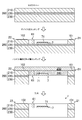
- FIG. 6 shows a manufacturing process of the shutter device 1. 6 corresponds to a cross-sectional view taken along the line II-II in FIG.
- an SOI wafer including a device layer (first silicon layer 210), a Box layer (oxide film layer 220), and a handle layer (second silicon layer 230) is prepared.
- the thickness of the device layer is 30 ⁇ m
- the thickness of the Box layer is 1 ⁇ m
- the thickness of the handle layer is 250 ⁇ m.
- the device layer is etched to integrally form a displacement enlarging mechanism including the fixed portion 2, the first actuator 3, the second actuator 4, the first beam 5, the second beam 6, and the driven member 7 in the device layer. .
- a displacement enlarging mechanism including the fixed portion 2, the first actuator 3, the second actuator 4, the first beam 5, the second beam 6, and the driven member 7 in the device layer.
- FIG. 6 only a part of the displacement enlarging mechanism is illustrated for convenience.
- the driven member 7 is formed thinly so that the thickness is about 7 ⁇ m by increasing the number of times of etching by one more than other members. That is, although not shown, the thickness of the driven member 7 is thinner than the thickness of the first actuator 3, the second actuator 4, the first beam 5, and the second beam 6. Further, the first electrode 101 is formed on the surface of the first base member 21, the second electrode 102 is formed on the surface of the second base member 22, and the metal film 71 is formed on the surface of the driven member 7.
- the electrodes 101 and 102 and the metal film 71 are Au / Ti films made of, for example, 20 nm thick Ti and 300 nm thick Au.
- the dummy wafer 250 is bonded to the device layer with the wax 240, and the back layer of the shutter device 1, that is, the Box layer and the handle layer are etched.
- the SOI substrate 200 is left on the fixed portion 2, and the first actuator 3, the second actuator 4, the first beam 5, the second beam 6, and the driven member that are movable members in other displacement enlarging mechanisms Only the device layer is left on the member 7.
- the displacement magnifying mechanism includes the fixed portion 2, the first actuator 3 and the second actuator 4 connected to the fixed portion 2, the first end 5 a and the second end 5 b, and the first end 5a includes a first beam 5 connected to the first actuator 3, a third end 6b and a fourth end 6c, and the third end 6b connected to the second actuator 4; And a driven member 7 connected to the second end 5b of the first beam 5 and the fourth end 6c of the second beam 6, and the first beam 5 is connected to the first beam 5 from the second end 5b.
- the second beam 6 is configured to push the driven member 7 in the extending direction of the second beam 6 from the fourth end 6c.
- the first actuator 3 and the second actuator 4 are connected to the fixed portion 2, the first end 5 a of the first beam 5 is connected to the first actuator 3, and the second beam 6
- the third end 6b of the first beam 5 is connected to the second actuator 4 and the driven member 7 is connected to the second end 5b of the first beam 5 and the fourth end 6c of the second beam 6.
- the first beam 5 pulls the driven member 7 from the second end portion 5b in the extending direction of the first beam 5, while the second beam 6 is driven from the fourth end portion 6c in the extending direction of the second beam 6. Pushing the member 7 drives the driven member 7 connected to these two beams 5 and 6.
- the driving force of the first beam 5 and the second beam 6 driven by the first actuator 3 and the second actuator 4 is added to drive the driven member 7. Therefore, the driven member 7 can be greatly displaced by a slight displacement of the first actuator 3 and the second actuator 4 which are driving members.
- the shutter device 1 is disposed on the displacement magnifying mechanism integrally formed of a semiconductor material and a fixed portion 2 of the displacement magnifying mechanism, and the first end 3b of the first actuator 3 of the displacement magnifying mechanism. And the first electrode 101 electrically connected to the first end 4b of the second actuator 4 and the second electrode of the first actuator 3 of the displacement magnifying mechanism disposed on the fixed portion 2 of the displacement magnifying mechanism. An end 3c and a second electrode 102 electrically connected to the second end 4c of the second actuator 4 are provided, and the optical path is blocked and opened by the driven member 7 of the displacement magnifying mechanism.
- the driven member 7 can be greatly displaced by applying a low voltage between the first electrode 101 and the second electrode 102.
- each of the first actuator 3 and the second actuator 4 may be composed of one actuator (see FIGS. 12 to 18 (B), 21 and 22).
- the size and structure of the first actuator 3 and the second actuator 4 do not need to be the same and may be different from each other.
- the number of actuators constituting the first actuator 3 and the second actuator 4 may be different, for example, the first actuator 3 is constituted by one actuator and the second actuator 4 is constituted by two actuators.
- the length of the member constituting the first actuator 3 and the length of the member constituting the second actuator 4 may be different.
- the actuator driving method may be different, for example, the first actuator 3 may be a thermal driving method and the second actuator 4 may be a capacitance driving method.
- the driven member 7 may be driven by driving only one of the first actuator 3 and the second actuator 4. Further, either one of the first actuator 3 and the second actuator 4 may be omitted (see FIGS. 21 and 22). In all the embodiments including modifications described below, the above-described configuration can be applied to corresponding members.
- FIG. 7 is a plan view of the shutter device 1A according to the first modification.
- the first member 61 of the second beam 6 is located between the first member 61 and the second member 62 along the second member 62 and the driven member 7 from the end 6a to the third end 6b. It is formed in a bowl-like shape that makes the space of the space narrower. Further, as compared with the configuration of FIG. 1, the first member 61 of the second beam 6 is formed with thinned portions (holes) 611, 611,. Thereby, the mass of the 1st member 61 becomes small and the effect that a resonant frequency rises is acquired.
- a heat-driven actuator when a heat-driven actuator is used, heat dissipation is promoted by increasing the surface area of the first member 61 due to a part of the second beam 6, that is, the thinning structure of the first member 61.
- the heat transmitted to the driven member 7 can be reduced.
- a lightening portion can be provided in one or both of the first beam 5 and the second beam 6 as necessary.
- a high elasticity formed slightly wider in order to make the elasticity in the substrate surface direction higher than other regions of the second member 62.
- a region 621 is provided.
- stress is concentrated at the central portion in the longitudinal direction and deformation is likely to occur, and deformation can be suppressed by increasing the elasticity (rigidity) of the central portion.
- by providing a highly elastic region 621 at the center in the longitudinal direction of the second member 62 formed in a rod shape the deformation of the part can be suppressed, and the first beam 5 is preferentially deformed to be driven.
- a decrease in the amount of movement of the member 7 can be prevented.
- the highly elastic region 621 of the second member 62 is formed wider than the other regions of the second member 62, the surface area of the second member 62 is increased, so that the heat dissipation effect is increased and the heat is increased.
- This can be a heat dissipation region that can reduce heat transfer to the driven member 7 when a driving actuator is used.
- the second member 62 may be formed thick, or another metal film may be formed.
- the part of the part may be formed to be thin.
- the elastic modulus of a part of the second member 62 of the second beam 6 is relatively higher or lower than that of the other parts.
- the first member 61 of the second beam 6 is also second. A configuration similar to that of the member 62 may be used to make the elastic modulus of some regions relatively higher or lower than other regions.
- the two actuators 31, 31 constituting the first actuator 3 there are other regions of the actuator 31 in the central part of the intermediate part 3 a and the first end part 3 b and the central part of the intermediate part 3 a and the second end part 3 c.
- high elasticity regions 32, 32, 32, 32 formed slightly wider are provided.
- the middle part 4 a and the center part of the first end part 4 b and the middle part 4 a and the center part of the second end part 4 c are connected to other parts of the actuator 41.
- the high elasticity region 32 has a relatively higher elastic modulus than other regions of the actuator 31, that is, the peripheral regions of the first end 3b, the second end 3c, and the intermediate portion 3a.
- the amount of deflection of the highly elastic region 32 is smaller than the amount of deflection of each of these peripheral regions, so that the amount of deformation near the first end 3b, near the second end 3c, and near the intermediate portion 3a is large.
- the actuators 31 and 41 may be formed thickly or other metal films may be formed.
- each corner portion is chamfered to have a curved shape.
- each opening By making each opening have such a shape, it is possible to suppress stress concentration on the corner and to increase the rigidity of the opening.
- stress may concentrate on the corner portion due to a difference in thermal expansion coefficient between the shutter device 1A and the mounting substrate, and the shutter device 1A may be deformed. is there. If this deformation is large, cracks may occur in the first and second base members 21 and 22, or the shutter device 1A may be damaged in some cases.
- the structure in which the corner portion is chamfered can be applied to the shutter device 1A shown in FIG. 1 and the configuration shown in the following modifications.
- FIG. 8 is a plan view of the shutter device 1B according to the second modification.
- the second beam 6 is so formed that the distance between the first member 61 and the second member 62 of the second beam 6 gradually decreases toward the end 6a.
- Six first members 61 are formed slightly obliquely with respect to the second member 62.
- the second beam 6 can transmit the driving force of the second actuator 4 to the driven member 7 as in the shutter device 1A of FIG. it can.
- FIG. 9 is a plan view of a shutter device 1C according to the third modification.
- the shutter device 1C is obtained by adding a connecting member 8 to the shutter device 1A of FIG.
- the connecting member 8 is a hairpin-shaped member formed in the opening 20 ⁇ / b> L, and the first end 8 a is connected in the vicinity of the first end 5 a of the first beam 5,
- the second end portion 8b is extended and folded back so as to be separated in a substantially vertical direction, the second end portion 8b is connected to the vicinity of the end portion 6a of the second beam 6, and the first beam 5 and the second beam 6 are connected to each other.
- a portion of the first beam 5 where the first end 8a of the connecting member 8 is connected, that is, the vicinity of the first end 5a of the first beam 5, is formed slightly thicker to increase the strength.
- the connecting member 8 extends from the vicinity of the end 6a of the second beam 6 in a direction substantially perpendicular to the second beam 6 and extends to the fixing portion 2 (more specifically, the second portion 6a). May be connected to the base member 22), and when the first member 61 rotates, the first member 61 and the fixing portion 2 (more specifically, the second base member 22) contact to prevent rotation.
- An anti-rotation structure (not shown) may be provided on the fixed portion 2 or the first member 61.
- the extending direction of the connecting member 8 does not have to be substantially perpendicular to the first beam 5 and the second beam 6, and may be any direction that intersects the first beam 5 and the second beam 6.
- FIG. 10 is a plan view of a shutter device 1D according to the fourth modification.
- the shutter device 1D is obtained by adding buffer members 23L, 24L, 25L, 23R, 24R, and 25R to the shutter device 1A of FIG.
- the first base member 21 and the second base member 22 constituting the fixed portion 2 are formed to have a shorter length in the Y direction at both the left and right ends in the X direction than the shutter device 1A in FIG. Yes.
- the buffer member 24L is disposed at the center between the first base member 21 and the second base member 22 at the left end in the X direction of the shutter device 1D, and the buffer members 23L and 25L are disposed above and below in the Y direction. That is, the buffer members 23L, 24L, and 25L are provided on the fixed portion 2, and are formed from a part of the left side in the X direction of the shutter device 1D that is rectangular in plan view.
- the buffer members 23L, 24L, and 25L have protrusions 26L, 27L, and 28L that protrude to the right in the X direction.
- the buffer member 24R is disposed at the center between the first base member 21 and the second base member 22 at the right end in the X direction of the shutter device 1D, and the buffer members 23R and 25R are disposed above and below in the Y direction. ing. That is, the buffer members 23R, 24R, and 25R are provided on the fixed portion 2 and are formed from a part of the right side in the X direction of the rectangular shutter device 1D in plan view.
- the buffer members 23R, 24R, and 25R have protrusions 26R, 27R, and 28R that protrude to the left in the X direction, respectively.
- the second actuator 4 When the second actuator 4 is driven and bent or curved to some extent so that it protrudes to the right in the X direction, the second actuator 4 comes into contact with the tips of the projections 26R, 27R, 28R, and the intermediate portion 4a of the second actuator 4 As described above, it is restrained not to drive to the right in the X direction.
- the driven member 7 is driven more than necessary and collides with the first base member 21. It can be prevented from being damaged. Further, since the buffer members 23L, 24L, 25L, 23R, 24R, and 25R are formed in independent island shapes, when the first actuator 3 comes into contact with the protrusions 26L, 27L, and 28L, the first actuator 3 When heat is transmitted to the buffer members 23L, 24L, and 25L to be easily dissipated, and the second actuator 4 comes into contact with the protrusions 26R, 27R, and 28R, the second actuator 4 moves to the buffer members 23R, 24R, and 25R.
- the first actuator 3 and the second actuator 4 When the first actuator 3 and the second actuator 4 come into contact with the protrusions of the buffer members, the current flowing through the first actuator 3 and the second actuator 4 flows into the buffer members, but the buffer members 23L, 24L, and 25L. , 23R, 24R, 25R, the first base member 21 and the second base member 22 are electrically insulated from each other and have a high electric resistance, so that the current flowing through the first actuator 3 and the second actuator 4 is buffered. Even if it flows into the member, the driving of the first actuator 3 and the second actuator 4 is not affected.
- FIG. 11 is a plan view of a shutter device 1E according to the fifth modification.
- the shutter device 1E is obtained by adding buffer members 24L and 24R having shapes different from those of the shutter device 1D of FIG. 10 to the shutter device 1A of FIG. Also, unlike the shutter device 1D of FIG. 10, the first actuator 3 and the second actuator 4 are formed flat without protrusions in the intermediate portion 3a and the intermediate portion 4a.
- the first base member 21 and the second base member 22 constituting the fixed portion 2 are formed so that the lengths in the Y direction at the left and right ends in the X direction are shorter than those in the shutter device 1A in FIG. Yes.
- the buffer member 24L is disposed between the first base member 21 and the second base member 22 at the left end in the X direction of the shutter device 1E. That is, the buffer member 24L is formed from a part of the left side in the X direction of the rectangular shutter device 1E in plan view.
- the buffer member 24L is formed so as to protrude slightly from the opening 20L.
- the buffer member 24R is disposed between the first base member 21 and the second base member 22 at the right end in the X direction of the shutter device 1E. That is, the buffer member 24R is formed from a part of the right side in the X direction of the shutter device 1E having a rectangular shape in plan view. Further, the buffer member 24R is formed so as to protrude slightly from the opening 20R.
- the second actuator 4 When the second actuator 4 is driven and bent or curved to some extent so as to protrude to the right in the X direction, the second actuator 4 comes into contact with the left end of the buffer member 24R in the X direction and the intermediate portion 4a of the second actuator 4 As described above, it is restrained not to drive to the right in the X direction. That is, it can be said that the buffer members 23L, 24L, and 25L are disposed within the drive range of the first actuator 3, and the buffer members 23R, 24R, and 25R are disposed within the drive range of the second actuator 4, respectively.
- the driven member 7 is driven more than necessary and collides with the first base member 21. It can be prevented from being damaged.
- the buffer members 24L and 24R are formed in independent island shapes, when the first actuator 3 comes into contact with the buffer member 24L, heat is transmitted from the first actuator 3 to the buffer member 24L and is easily radiated.
- the second actuator 4 comes into contact with the buffer member 24R, heat is transmitted from the second actuator 4 to the buffer member 24R so that the heat is easily radiated, and the temperature increase of the first actuator 3 or the second actuator 4 is suppressed. can do.
- the area of the contact portion between the first actuator 3 and the buffer member 24L and the area of the contact portion between the second actuator 4 and the buffer member 24R are wider. Therefore, heat transfer from the first actuator 3 or the second actuator 4 to these buffer members is large. For this reason, the suppression effect of the temperature rise of the 1st actuator 3 or the 2nd actuator 4 is high.
- the driven member 7 when the driven member 7 is driven, the first actuator 3 is driven to contact the buffer member 24L or the second actuator 4 is driven to contact the buffer member 24R. It is also possible to prevent the first member 61 from rotating more than necessary counterclockwise about the third end 6b.
- the first actuator 3 and the second actuator 4 When the first actuator 3 and the second actuator 4 come into contact with the end portions of the buffer members, the current flowing through the first actuator 3 and the second actuator 4 flows into the buffer members, but the buffer members 24L, 24R, Since the first base member 21 and the second base member 22 are electrically insulated from each other and have a high electric resistance, even if a current flowing through the first actuator 3 and the second actuator 4 flows into these buffer members, the first actuator 3 And the driving of the second actuator 4 is not affected.
- FIG. 12 is a plan view of the shutter device 1F according to the sixth modification.
- the first actuator 3 and the second actuator 4 are each constituted by one actuator.
- the positional relationship between the first beam 5 and the second beam 6 is upside down in the Y direction compared to the shutter devices 1, 1A to 1E.
- the driving direction of the driven member 7 on the XY plane is opposite to that of the shutter devices 1 and 1A to 1E, and the driven member 7 is driven diagonally to the left on the XY plane.
- the driving direction of the driven member 7 varies depending on the rigidity and shape of the first beam 5 and the second beam 6, and can be driven in other directions such as a lower left side and a lower side.
- the second beam 6 is formed at the center in the longitudinal direction of the second member 62 to be slightly wider, for example, in order to make the elasticity in the substrate surface direction higher than other regions of the second member 62.
- a highly elastic region 621 is provided. As described above, by providing the high elasticity region 621 in the central portion of the second member 62 formed in a rod shape, it is possible to prevent a decrease in the amount of movement of the driven member 7 due to deformation of the central portion of the second member 62. it can.
- the highly elastic region 621 of the second member 62 is formed wider than the other regions of the second member 62, the surface area of the second member 62 is increased, so that the heat dissipation effect is increased and the heat is increased.
- This can be a heat dissipation region that can reduce heat transfer to the driven member 7 when a driving actuator is used.
- the second member 62 may be formed thick, or another metal film may be formed.
- the part of the part may be formed to be thin.
- the elastic modulus of a part of the second member 62 of the second beam 6 is relatively higher or lower than that of the other parts.
- the first member 61 of the second beam 6 is also second. A configuration similar to that of the member 62 may be used to make the elastic modulus of some regions relatively higher or lower than other regions.
- a region having a relatively higher elastic modulus than the other regions in the first beam 5 may be provided at the center of the first beam 5.
- the shutter device 1F includes a connecting member 8.
- the connecting member 8 is a hairpin-shaped member formed in the opening 20 ⁇ / b> L, and the first end 8 a is connected in the vicinity of the first end 5 a of the first beam 5,
- the second end portion 8b is extended and folded back so as to be separated in a substantially vertical direction, the second end portion 8b is connected to the vicinity of the end portion 6a of the second beam 6, and the first beam 5 and the second beam 6 are connected to each other.
- a portion of the first beam 5 where the first end 8a of the connecting member 8 is connected, that is, the vicinity of the first end 5a of the first beam 5, is formed slightly thicker to increase the strength.
- the connecting member 8 By providing such a connecting member 8, when the third end portion 6b of the second beam 6 is driven, the first member 61 of the second beam 6 rotates clockwise on the XY plane with the third end portion 6b as an axis. The amount of drive of the driven member 7 can be further increased. When a thermally driven actuator is employed, heat is transferred to the driven member 7 because heat is dissipated even in the connecting member 8. Further, the driving amount of the third end 6b by the second actuator 4 is not greatly reduced. Furthermore, as another example for preventing the rotation, the connecting member 8 extends from the vicinity of the end 6a of the second beam 6 in a direction substantially perpendicular to the second beam 6 and extends to the fixed portion 2 (more specifically, the first portion 6a).
- the first member 61 and the fixing portion 2 are in contact with each other when the first member 61 rotates, thereby preventing rotation.
- An anti-rotation structure (not shown) may be provided on the fixed portion 2 or the second member 62.
- the extending direction of the connecting member 8 does not have to be substantially perpendicular to the first beam 5 and the second beam 6, and may be any direction that intersects the first beam 5 and the second beam 6.
- FIG. 13 is a plan view of a shutter device 1G according to Modification 7.
- the shutter device 1G is obtained by removing the connecting member 8 from the shutter device 1F of FIG. 12 and adding buffer members 29a and 29a.
- the first base member 21 and the second base member 22 constituting the fixed portion 2 are partially cut out at the right side in the X direction to form cutout portions 29, 29.
- Buffer members 29a and 29a are disposed at 29 and 29, respectively.
- the buffer members 29 a and 29 a are formed so as to protrude to the left in the X direction from the second recess 21 b of the first base member 21 and the fourth recess 22 b of the second base member 22.
- the buffer member 29a is formed with thinned portions (holes) 29b, 29b,.
- the driven member 7 is driven more than necessary and collides with the second base member 22 and is damaged. Can be prevented.
- the first member 61 of the second beam 6 has the third end 6b as an axis when the driven member 7 is driven. It is also possible to prevent the clockwise rotation more than necessary.
- the cross-sectional area can be reduced and the thermal resistance can be increased, and the buffer members 29a, 29a are further extended from the oxide film layer 220 in the X direction. Since it is provided so as to protrude to the left side, the escape of heat from the second actuator 4 to the buffer members 29a, 29a can be suppressed.
- the second actuator 4 When the second actuator 4 abuts against the tips of the buffer members 29a and 29a, the current flowing through the second actuator 4 flows into the buffer members 29a and 29a. However, the buffer members 29a and 29a, the first base member 21 and the second Since the base member 22 is electrically insulated from each other and has a high electric resistance, even if a current flowing through the first actuator 3 and the second actuator 4 flows into these buffer members, the first actuator 3 and the second actuator 4 are driven. Does not affect.
- FIG. 14 is a plan view of a shutter device 1H according to Modification 8.
- the shutter device 1H differs from the shutter device 1F of FIG. 12 in that the second member 62 of the first beam 6 is formed with a substantially uniform width.
- FIG. 15 is a plan view of the shutter device 1I according to the ninth modification.
- the second member 62 of the first beam 5 and the second beam 6 in the shutter device 1F of FIG. 12 is formed in a slightly curved shape. More specifically, in the initial state where the driven member 7 is not driven by the first actuator 3 and the second actuator 4, the curvatures of the first beam 5 and the second member 62 of the second beam 6 that are in parallel are different. It is formed in a slightly curved shape.
- the second member 62 may have a linear shape and the first beam 5 may have a slightly curved shape.
- the curvature of the second member 62 is X and the curvature of the first beam 5 is Y
- the first actuator 3 and the second actuator 4 are driven more than the second member 62 when driven. Since the first beam 5 is deformed first, the driven member 7 can be driven more greatly, or the driving force required to drive the driven member 7 can be reduced.
- the shutter device 1I when the first actuator 3 and the second actuator 4 are driven, the second members 62 of the first beam 5 and the second beam 6 are greatly curved or bent with different curvatures, and the driven member 7 is moved to XY. Push down diagonally to the left on the plane. Therefore, the second members 62 of the first beam 5 and the second beam 6 are formed in advance slightly curved in the driving direction of the driven member 7. Thus, when the first actuator 3 and the second actuator 4 are driven, the first beam 5 and the second beam 6 are easily bent or bent in a predetermined direction.
- FIG. 16 is a plan view of a shutter device 1J according to the tenth modification.
- the second beam 6 is so formed that the distance between the first member 61 and the second member 62 of the second beam 6 gradually decreases toward the end 6a.
- Six first members 61 are formed slightly obliquely with respect to the second member 62.
- the second beam 6 can transmit the driving force of the second actuator 4 to the driven member 7 in the same manner as the shutter device 1J.
- the first actuator 3 and the second actuator 4 are formed flat without protrusions in the intermediate portion 3a and the intermediate portion 4a.
- the central portion between the intermediate portion 3 a and the first end portion 3 b and the central portion between the intermediate portion 3 a and the second end portion 3 c are more in the substrate surface direction than other regions of the first actuator 3.
- high elasticity regions 32 and 32 formed slightly wider are provided.
- the central portion of the intermediate portion 4 a and the first end portion 4 b and the central portion of the intermediate portion 4 a and the second end portion 4 c are more substrate surface than other regions of the second actuator 4.
- high elasticity regions 42 and 42 formed slightly wider are provided.
- FIG. 17 is a plan view of the shutter device 1K according to the eleventh modification.
- the first beam 5 having the first end 5a connected to the intermediate portion 3a of the first actuator 3 is connected to the driven member 7 at the second end 5b.
- the second beam 6 having the third end 6b connected to the intermediate portion 4a of the second actuator 4 is connected to the driven member 7 at the fourth end 6c.
- the second beam 6 has a first member 61 and a second member 62, and the first member 61 extends to the left side in the X direction of the third end 6b while bypassing the Y direction upper side of the driven member 7. Moreover, it has a lightening part (hole) 611, 611.
- the second member 62 of the second beam 6 extends from the connecting portion with the first member 61 to the right in the X direction. Further, the first beam 5 and the first member 61 of the second beam are connected by the connecting member 8 in the vicinity of the first end 5 a of the first beam 5.
- the difference from the shutter device 1I shown in FIG. 15 is that the first beam 5 and the second beam 6 are first provided with hinges 91 to 94. Specifically, a hinge 91 is provided on the proximal end side of the second member 62 of the second beam 6, and the first member 61 and the second member 62 of the second beam 6 are connected. A hinge 92 is provided on the proximal end side of the first beam 5 in the parallel arrangement portion 56.
- a hinge 93 is provided on the distal end side of the second beam 6, and a hinge 94 is provided on the distal end side of the first beam 5. That is, in the parallel arrangement portion 56, hinges 91 to 94 are provided on both ends of each beam. The elastic modulus of the hinges 91 to 94 is lower than that of the second member 62 of the first beam 5 and the second beam 6. Further, in the parallel arrangement portion 56, the intermediate portion between the hinge 92 and the hinge 94 has a lightening portion (hole) 501, 501... In a part of the first beam 5, and the intermediate portion between the hinge 91 and the hinge 93 is .. Are formed in a part of the second member 62 of the second beam 6.
- the hinges 91 to 94 are deformed.
- the deformation amount of the second member 62 itself of the first beam 5 and the second beam 6 is suppressed, so that these beams push and pull the driven member 7 from the same side while maintaining a substantially parallel relationship.
- the driving amount of the driven member 7 is not reduced.
- the lengths of the second members 62 of the first beam 5 and the second beam 6 become longer, their rigidity decreases and the deformation becomes easier, so that the effect of providing the hinges 91 to 94 becomes greater.
- the lengths, shapes, and the like of the hinges 91 to 94 are not particularly limited to the configuration shown in FIG. 17, and are appropriately determined according to the design specifications of the shutter device 1K. Further, by providing the second member 62 of the first beam 5 and the second beam 6 with the thinned portions (holes) 501, 501... And the thinned portions (holes) 622, 622.
- the heat transmitted from the first actuator 3 and the second actuator 4 to the first beam 5 and the second beam can be dissipated by the heat dissipation structure so that a large amount of heat is not transmitted to the driven member 7. Furthermore, since the masses of the first beam 5 and the second beam can be reduced, the resonance frequency can be increased. In the parallel arrangement portion 56, the portions where the thinned portions (holes) 501, 501... And the thinned portions (holes) 622, 622. In addition, the width of the first beam 5 and the second beam 6 is increased so that the second member 62 is prevented from being deformed.
- FIG. 18A and 18B are plan views of the shutter device 1L according to the modification 12.
- FIG. 18A shows the shutter device 1L before driving
- FIG. 18B shows the shutter device 1L during driving.
- the cantilevers 301 and 302 are provided in the opening 20 ⁇ / b> L between the first and second base members 21 and 22 and the first actuator 3, and the first and second base members 21. , 22 and the second actuator 4 are provided with cantilevers 303 and 304 in the opening 20R.
- the cantilevers 301 to 304 are respectively connected to the intermediate portion 3a of the first actuator 3 to which the first beam 5 is connected from the first base member 21 and the second base member 22 and the first member 61 of the second beam 6 is connected.
- the actuator 4 is provided so as to extend toward the intermediate portion 4a.
- each of the cantilevers 301 to 304 has flexibility so that it can be displaced within a predetermined range with the connecting portion between the first base member 21 and the second base member 22 as a fulcrum.
- the cantilevers 301 and 302 are provided within the driving range of the first actuator 3, and the cantilevers 303 and 304 are provided within the driving range of the second actuator 4.
- the cantilevers 301 to 304 are used together with the fixed portion 2, the first actuator 3, the second actuator 4, the first beam 5, and the second beam 6 by etching the device layer in the manufacturing process shown in FIG. It is integrally formed.
- a contact portion 3d having a flat tip on the left side in the X direction is provided on the fixed portion 2 side.
- the third base member 23 of the fixed portion 2 facing 3d is provided with a contact portion 23a having a flat tip.
- the tip of the contact portion 3d and the tip of the contact portion 23a have substantially the same width.
- the intermediate portion 4a of the second actuator 4 is provided with an abutting portion 4d on the right side in the X direction similarly to the intermediate portion 3a of the first actuator 3, and the abutting portion 4d.
- a contact portion 23a is provided on the third base member 23 facing the surface.
- tip of the contact part 23a does not necessarily need to be the same, and both may differ.
- the size of the contact part 3d and the contact part 23a is not limited to FIGS. 18A and 18B, and may be larger than this.
- first silicon layer 210 is removed between the first base member 21 and the third base member 23 and between the second base member 22 and the third base member 23.
- the contact portions 23a, 23a and the cantilevers 301 to 304 are electrically insulated, and when the first actuator 3 or the second actuator 4 contacts the contact portion 23a or the cantilevers 301 to 304, An unnecessary current bypass can be prevented from being formed.
- the first actuator 3 when the first actuator 3 is energized and driven, the first actuator 3 having both end portions 3b and 3c fixed to the fixed portion 20 is bent or bent to the left in the X direction shown in FIG. At this time, the cantilevers 301 and 302 abut against the first actuator 3, so that the displacement of the first actuator 3 is suppressed. Further, when the first actuator 3 comes into contact with the cantilevers 301 and 302, the flexible cantilevers 301 and 302 are displaced in a predetermined range toward the left side in the X direction, and the impact when the first actuator 3 comes into contact. To ease. As a result, the displacement of the first actuator 3 is regulated by the cantilevers 301 and 302 without being damaged.
- the contact portion 3d provided on the first actuator 3 is provided on the fixed portion 2. Since it abuts against the abutting portion 23a, it is possible to restrict the displacement of the first actuator 3 beyond that. Further, since the abutting portion 3d and the abutting portion 23a are in contact with each other, displacement of the first actuator 3 is restricted, and damage to the first actuator 3 can be reliably prevented. Furthermore, since the heat generated in the first actuator 3 is directly dissipated to the third base member 23 due to the contact between the contact portion 3d and the contact portion 23a, the temperature rise in the first actuator 3 can be suppressed.
- the contact portion 3d and the contact portion 23a temperature variations in the first actuator 3 can be suppressed. Breakage and damage due to heat and stress can be suppressed. Further, it is possible to suppress the heat generated by the first actuator 3 from being propagated to the driven member 7 via the first beam 5 or the second member 62 of the second beam. Thereby, for example, in the driven member 7, it is possible to prevent silicon from diffusing into the metal film 71 and to prevent changes in optical characteristics such as inability to block light.
- the heat generated in the first actuator 3 is dissipated to the first base member 21 and the second base member 22, so that the temperature rise in the first actuator 3 can be suppressed.
- the provision of the contact portions 4d and 23a and the cantilevers 303 and 304 enables the displacement of the second actuator 4 to be restricted and the temperature rise to be suppressed as described above.
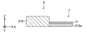
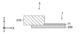
- 19A and 19B are plan views of driven members according to the modified example 13, and correspond to the cross-sectional view shown in FIG.
- the driven member 7 is formed thinner than the other members constituting the displacement enlarging mechanism, so that the mass of the driven member 7 is increased.
- the resonance frequency is increased by decreasing the frequency.
- the driven member 7 is formed thinner than the other members constituting the displacement magnifying mechanism, or alternatively, the material is different from that of the other members. By doing so, the resonance frequency is increased.
- the driven member 7 has a laminated structure of a porous silicon layer 210a and a metal film 71. Since the porous silicon layer 210a has a lower density than the first silicon layer 210, the mass of the driven member 7 is smaller than that when the driven member 7 is formed of the first silicon layer 210 as shown in FIG. can do.
- the driven member 7 has a laminated structure of the oxide film layer 220 and the metal film 71. Since the oxide film layer 220 also has a lower density than the first silicon layer 210, the mass of the driven member 7 is made smaller than that when the driven member 7 is formed of the first silicon layer 210 as shown in FIG. 4. be able to.
- the oxide film layer 220 is partially left below the first and second beams 5 and 6. .
- the porous silicon layer 210a is formed in a region where the driven member 7 is to be formed in advance by an anodic oxidation method or the like before etching the device layer.
- the displacement enlarging mechanism is integrally formed with the porous silicon layer 210a formed.
- the oxide film layer 220 is formed with the first and second beams 5 and 5 in order to ensure the connection strength between the driven member 7 and the first and second beams 5 and 6.
- the oxide film layer 220 may be left instead of being left partially in the lower layer 6, and the first silicon layer 210 may be left thin on the surface of the oxide film layer 220.
- both the porous silicon layer 210a and the oxide film layer 220 have a smaller thermal conductivity coefficient than the first silicon layer 210, the heat generated in the first actuator 3 and the second actuator 4 propagates to the driven member 7. The effect which suppresses can be improved.
- the above embodiment may be configured as follows.
- FIG. 20 shows a plan view of a shutter device 1M according to another embodiment of the present invention.
- the first base member 21 in the shutter device described so far is divided into two in the X direction to form a third base member 23.
- the third base member 23 is electrically insulated from the first base member 21 and the second base member 22, and the third electrode 103 is formed on the upper surface of the third base member 23.
- the second actuator 4 is disposed at the boundary between the first base member 21 and the third base member 23 and extends from the right end of the first base member 21 in the X direction to the lower side in the Y direction. And a second member 44 that is wider than the first member 43 and extends downward from the left end in the X direction of the third base member 23 in the Y direction.
- the first end 43 a of the first member 43 is connected to the first base member 21, the first end 44 a of the second member 44 is connected to the third base member 23, and the second end 43 b of the first member 43.
- the 2nd end part 44b of the 2nd member 44 is mutually connected.
- the third end 6 b of the second beam 6 is connected to the second end 44 b of the second member 44 of the second actuator 4.
- the driving force of the first beam 5 and the second beam 6 respectively driven by the first actuator 3 and the second actuator 4 is added to drive the driven member 7.
- the driven member 7 can be greatly displaced by a slight displacement of the first actuator 3 and the second actuator 4.
- fins, unevenness, cutouts, thinning structures, and the like may be provided on the second members 62 of the first beam 5 and the second beam 6 as heat dissipation structures.
- FIG. 21 shows a plan view of a shutter device 1N in which the first actuator 3 is omitted from the shutter device 1I of FIG.
- the first end 5a of the first beam 5 is connected to the first base member 21.
- the first end 5 a of the first beam 5 may be connected to the second base member 22 instead of the first base member 21.
- FIG. 22 is a plan view of the shutter device 1O in which the second actuator 4 is omitted from the shutter device 1I of FIG.
- the third end 6 b of the second beam 6 is connected to the first base member 21.
- the third end 6 b of the second beam 6 may be coupled to the second base member 22 instead of the first base member 21. Further, in the shutter device 1O, the second beam 6 is not directly connected to the member that generates heat, and it is not necessary to consider heat dissipation.
- a fixed part A first actuator and a second actuator coupled to the fixed portion; A first beam having a first end and a second end, wherein the first end is coupled to the first actuator; A second beam having a third end and a fourth end, wherein the third end is coupled to the second actuator; A driven member connected to the second end of the first beam and the fourth end of the second beam; The first beam and the second beam have a parallel arrangement part arranged in parallel with each other, and the driven member is connected to the parallel arrangement part, The first actuator is driven to pull the first beam from the second end side in the extending direction of the first beam, The second actuator is a displacement enlarging mechanism that drives the second beam to push the second beam from the fourth end side in the extending direction of the second beam.
- the displacement enlarging mechanism according to any one of appendices 1 to 4, wherein a high elasticity region is provided in a part of the first beam or the second beam that is bent by pushing the driven member.
- the driven member is formed thinner than the first beam and / or the second beam, and has a heat radiating portion formed by a difference in thickness between the driven member and the first beam or the second beam.
- a substrate A fixing portion provided on the substrate; A first actuator coupled to the fixed portion; A first beam having a proximal end connected to the first actuator and extending parallel to the upper surface of the substrate; A second actuator provided in the fixed portion; A second beam having a proximal end connected to the second actuator and extending parallel to the upper surface of the substrate; A driven member connected to the tip side of the first beam and the second beam; Have The tip side of the first beam is folded and connected to the tip side of the second beam; The first beam and the second beam have parallel arrangement portions arranged in parallel with each other, The first actuator pushes or pulls the driven member via the first beam, while the second actuator applies a force to the driven member via the second beam in a direction opposite to the first actuator.
- Displacement enlargement mechanism that works.
- Appendix 8 A substrate, A fixing portion provided on the substrate; An actuator provided in the fixed portion; A driven member provided in the substrate surface; A first beam extending at a distal end side connected to the driven member; A distal end portion side having a second beam extending in parallel with the driven member in parallel with the first beam; The proximal end side of the second beam is folded, One of the proximal end side of the first beam and the proximal end side of the second beam is connected to the actuator, and the other is connected to the fixed portion.
- the technique disclosed herein is useful for the displacement enlarging mechanism and the shutter device.
Landscapes
- Engineering & Computer Science (AREA)
- Physics & Mathematics (AREA)
- Computer Hardware Design (AREA)
- Microelectronics & Electronic Packaging (AREA)
- General Physics & Mathematics (AREA)
- Optics & Photonics (AREA)
- Mechanical Engineering (AREA)
- Micromachines (AREA)
- Shutters For Cameras (AREA)
- Mechanical Light Control Or Optical Switches (AREA)
Abstract
変位拡大機構は、固定部2と、固定部2に連結された第1及び第2アクチュエータ3,4と、第1及び第2端部5a,5bを有し、第1端部5aが第1アクチュエータ3に連結された第1ビーム5と、第3及び第4端部6b,6cを有し、第3端部6bが第2アクチュエータ4に連結された第2ビーム6と、第1及び第2ビーム5,6が互いに並列に配置された並列配置部56に連結された被駆動部材7とを備えている。第1アクチュエータ3は第2端部5b側から第1ビーム5をその延在方向に引くように駆動し、第2アクチュエータ4は第4端部6c側から第2ビーム6をその延在方向に押すように駆動する。
Description
ここに開示された技術は、変位拡大機構及びシャッタ装置に関するものである。
従前より、所定の光路を遮断及び開通させるシャッタ装置が知られている。例えば、特許文献1(特にFig.6を参照)に記載のシャッタ装置は、シャッタと、シャッタを駆動するアクチュエータとを備えた変位拡大機構とを含んでいる。アクチュエータは、ビームと、2つの辺部材とを備え、ビームはベース部材から伸び、ビームの端部が折り返されて第1辺部材に連結され、第1辺部材の端部が折り返されて第2辺部材に連結され、第2辺部材の端部は固定されている。シャッタは第1辺部材と第2辺部材との連結部分に取り付けられている。該変位拡大機構において、加熱によりビームが伸長すると第1辺部材及び第2辺部材が湾曲してシャッタが駆動される。
特許文献1に記載のシャッタ装置は、第2辺部材の端部が固定されていることで、シャッタの変位が第1辺部材に連結されたビームの変位に依存する。したがって、シャッタをより大きな振り幅で駆動するにはビームを大きく伸縮させなければならない。しかしながら、ビームの伸長には限界があり、あまり大きく伸長できないという問題がある。また、頻繁にビームを伸縮させると変形に伴う負荷がビームに蓄積されて最悪の場合ビームが破損するおそれがある。
ここに開示され技術は、かかる点に鑑みてなされたものであり、その目的とするところは、駆動部材のわずかな変位で被駆動部材を大きく変位させることができる変位拡大機構及びそのような変位拡大機構を備えたシャッタ装置を提供することにある。
ここに開示された変位拡大機構は、固定部と、前記固定部に連結された第1アクチュエータ及び第2アクチュエータと、第1端部及び第2端部を有し、前記第1端部が前記第1アクチュエータに連結された第1ビームと、第3端部及び第4端部を有し、前記第3端部が前記第2アクチュエータに連結された第2ビームと、前記第1ビームの前記第2端部と前記第2ビームの前記第4端部とに連結された被駆動部材とを備え、前記第1ビーム及び前記第2ビームは、互いに並列に配置された並列配置部を有し、当該並列配置部において前記被駆動部材が連結され、前記第1アクチュエータは、前記第1ビームを前記第2端部側から当該第1ビームの延在方向に引くように駆動し、前記第2アクチュエータは、前記第2ビームを前記第4端部側から当該第2ビームの延在方向に押すように駆動する。
この構成によれば、第1アクチュエータ及び第2アクチュエータが固定部に連結されており、第1ビームの第1端部が第1アクチュエータに連結されており、第2ビームの第3端部が第2アクチュエータに連結されており、被駆動部材が第1ビームの第2端部と第2ビームの第4端部とに連結されており、第1ビーム及び第2ビームは、互いに並列に配置された並列配置部を有し、並列配置部において被駆動部材が連結されている。第1アクチュエータは、第1ビームを第2端部側から第1ビームの延在方向に引くように駆動し、第2アクチュエータは、第2ビームを第4端部側から第2ビームの延在方向に押すように駆動する。すなわち、第1アクチュエータ及び第2アクチュエータにそれぞれ駆動される第1ビーム及び第2ビームの駆動力が足し合わされて被駆動部材が駆動される。
また、ここに開示されたシャッタ装置は、前記変位拡大機構と、前記変位拡大機構の前記固定部上に配設され、前記変位拡大機構の前記第1アクチュエータの第1端部及び前記第2アクチュエータの第1端部に電気的に接続された第1電極と、前記変位拡大機構の前記固定部上に配設され、前記変位拡大機構の前記第1アクチュエータの第2端部及び前記第2アクチュエータの第2端部に電気的に接続された第2電極とを備え、前記変位拡大機構の前記被駆動部材で光路を遮断及び開通させるものである。
この構成によれば、第1電極と第2電極との間に電圧が印加されると第1アクチュエータ及び第2アクチュエータに電流が流れ、第1アクチュエータ及び第2アクチュエータが加熱されて熱変形することで第1ビーム及び第2ビームが駆動されてこれら2つのビームに連結された被駆動部材が駆動される。
前記変位拡大機構によれば、駆動部材である第1アクチュエータ及び第2アクチュエータのわずかな変位で被駆動部材を大きく変位させることができる。また、そのような変位拡大機構を備えた前記シャッタ装置によれば、第1電極と第2電極との間に低い電圧の印加で被駆動部材を大きく変位させることができる。
以下、例示的な実施形態を図面に基づいて詳細に説明する。
図1は、本発明の一実施形態に係るシャッタ装置1の平面図を、図2は、シャッタ装置1の、図1のII-II線における断面図を示す。なお、発明者らは、当業者が本発明を十分に理解するために添付図面及び以下の説明を提供するのであって、これらによって特許請求の範囲に記載の主題を限定することを意図するものではない。また、図面に描かれた各部材の寸法、厚み、細部の詳細形状などは実際のものとは異なることがある。
[シャッタ装置の構成]
シャッタ装置1は、固定部2と、固定部2に連結された第1アクチュエータ3及び第2アクチュエータ4と、第1端部5a及び第2端部5bを有し、第1端部5aが第1アクチュエータ3に連結された第1ビーム5と、第3端部6b及び第4端部6cを有し、第3端部6bが第2アクチュエータ4に連結された第2ビーム6と、第1ビーム5の第2端部5bと第2ビーム6の第4端部6cとに連結された被駆動部材7と、第1電極101と、第2電極102とを備えている。
シャッタ装置1は、固定部2と、固定部2に連結された第1アクチュエータ3及び第2アクチュエータ4と、第1端部5a及び第2端部5bを有し、第1端部5aが第1アクチュエータ3に連結された第1ビーム5と、第3端部6b及び第4端部6cを有し、第3端部6bが第2アクチュエータ4に連結された第2ビーム6と、第1ビーム5の第2端部5bと第2ビーム6の第4端部6cとに連結された被駆動部材7と、第1電極101と、第2電極102とを備えている。
以下、説明の便宜上、第1ビーム5の長手方向をX方向、第1アクチュエータ3及び第2アクチュエータ4の長手方向をY方向、シャッタ装置1の厚み方向をZ方向と称する。なお、X方向において、図1における左側を単に左側、図1における右側を単に右側と称することもある。Y方向において、図1における上側を単に上側、図1における下側を単に下側と称することもある。Z方向において、図2における上側を上面、図2における下側を下面と称することもある。また、第1ビーム5の第1端部5aや第2ビーム6の第3端部6bを基端、第1ビーム5の第2端部5bや第2ビーム6の第4端部6cを先端と称することもある。
シャッタ装置1は、いわゆるMEMS(Micro ElectroMechanical Systems)シャッタであって、半導体微細加工技術を応用したマイクロマシニング技術で製造されている。シャッタ装置1は、SOI(Silicon on Insulator)基板200を用いて製造されている。SOI基板200は、単結晶シリコンで形成された第1シリコン層210と、SiO2で形成された酸化膜層220と、単結晶シリコンで形成された第2シリコン層230とがこの順で積層されて構成されている。
このように、シャッタ装置1において、固定部2、第1アクチュエータ3、第2アクチュエータ4、第1ビーム5、第2ビーム6、及び被駆動部材7は、シリコン素材で一体成形され、変位拡大機構を構成している。
なお、酸化膜層220及び第2シリコン層230は固定部2を構成する第1ベース部材21及び第2ベース部材22の下面にのみ残され、可動部材である第1アクチュエータ3、第2アクチュエータ4、第1ビーム5、第2ビーム6、及び被駆動部材7の下面の酸化膜層220及び第2シリコン層230は製造過程において除去される。
図1に示すように、例えば、シャッタ装置1は平面視で矩形の全体形状を有している。固定部2は、そのような平面視矩形のシャッタ装置1の全体形状を形成するフレームである。固定部2は、Y方向に対向して配置された第1ベース部材21及び第2ベース部材22を備えている。ここで、図1において、シャッタ装置1のY方向上側の辺を第1辺、それに対向するY方向下側の辺を第2辺、X方向左側の辺を第3辺、それに対向するX方向右側の辺を第4辺とすると、第1ベース部材21は、第1辺、第3辺の一部、及び第4辺の一部から形成されている。また、第2ベース部材22は、第2辺、第3辺の別の一部、及び第4辺の別の一部から形成されている。第1ベース部材21及び第2ベース部材22は、いずれも、第1アクチュエータ3、第2アクチュエータ4、第1ビーム5、第2ビーム6及び被駆動部材7の可動域を確保しつつできるだけ広い面積を占める形状にされている。
なお、固定部2は、第1シリコン層210において第1ベース部材21及び第2ベース部材22の2つのパーツに分かれているが、酸化膜層220及び第2シリコン層230では1つに繋がっている。このため、第1ベース部材21及び第2ベース部材22の相対位置は固定されており、第1ベース部材21及び第2ベース部材22で可動部材を支持することができる。
第1ベース部材21は、対向する第2ベース部材22に向けて開口する第1凹部21a及び第2凹部21bを有する。第1凹部21aは、第1ベース部材21のX方向左側端部に配置されている。第2凹部21bは、第1ベース部材21のX方向右側端部に配置されている。
第2ベース部材22は、対向する第1ベース部材21に向けて開口する第3凹部22a及び第4凹部22bを有する。第3凹部22aは、第2ベース部材22のX方向左側端部に配置されている。第4凹部22bは、第2ベース部材22のX方向右側端部に配置されている。
さらに、第1ベース部材21の第1凹部21aと第2ベース部材22の第3凹部22aとは開口が互いに対向する位置に配置され、第1アクチュエータ3を配置するためのY方向に長い概略矩形の開口部20Lを形成している。同様に、第1ベース部材21の第2凹部21bと第2ベース部材22の第4凹部22bとは開口が互いに対向する位置に配置され、第2アクチュエータ4を配置するためのY方向に長い概略矩形の開口部20Rを形成している。第1ベース部材21及び第2ベース部材22において当該開口部20L,20R以外の部分は比較的大きな面積のパターンが占めている。より詳細には、略矩形状に形成された固定部2のX方向左側の第3辺に沿って開口部20Lが形成され、当該第1辺と対向する固定部2のX方向右側の第4辺に沿って開口部20Rが形成され、これら対向する開口部20L及び開口部20Rにそれぞれ第1アクチュエータ3及び第2アクチュエータ4が対向するように設けられている。
このように、固定部2は、可動部材の可動域を確保しつつできるだけ広い面積を占めるような形状にされていることで、第1アクチュエータ3及び第2アクチュエータ4を支持するフレームとして必要な高い剛性を確保している。
第1アクチュエータ3は、並列配置された2つのアクチュエータ31,31を備えている。2つのアクチュエータ31,31は、Y方向に伸びた棒状の部材であり、第1アクチュエータ3の第1端部3bから第2端部3cへの長手方向の略中央の中間部3aにおいて互いに連結されている。このように、2つのアクチュエータ31,31が中間部3aにおいて連結されていることで、2つのアクチュエータ31,31の各駆動力が結合されて第1アクチュエータ3は大きな駆動力を発揮することができる。後述するように、第1アクチュエータ3は通電による加熱で熱膨張して駆動力を発生させる。
2つのアクチュエータ31,31の第1端部3b,3bは、第1ベース部材21の第1凹部21aの底面部分において第1ベース部材21に連結されている。2つのアクチュエータ31,31の第2端部3c,3cは、第2ベース部材22の第3凹部22aの底面部分において第2ベース部材22に連結されている。
厳密に言うと、第1アクチュエータ3は、Y方向に一直線に伸びているわけではなく、中間部3aがその駆動方向であるX方向左側に突出するようにわずかに屈曲、あるいは全体的にX方向左側に膨らむようにわずかに湾曲している。
第2アクチュエータ4は、並列配置された2つのアクチュエータ41,41を備えている。2つのアクチュエータ41,41は、Y方向に伸びた棒状の部材であり、第2アクチュエータ4の第1端部4bから第2端部4cへの長手方向の略中央の中間部4aにおいて互いに連結されている。このように、2つのアクチュエータ41,41が中間部4aにおいて連結されていることで、2つのアクチュエータ41,41の各駆動力が結合されて第2アクチュエータ4は大きな駆動力を発揮することができる。後述するように、第2アクチュエータ4は通電による加熱で熱膨張して駆動力を発生させる。
2つのアクチュエータ41,41の第1端部4b,4bは、第1ベース部材21の第2凹部21bの底面部分において第1ベース部材21に連結されている。2つのアクチュエータ41,41の第2端部4c,4cは、第2ベース部材22の第4凹部22bの底面部分において第2ベース部材22に連結されている。
厳密に言うと、第2アクチュエータ4は、Y方向に一直線に伸びているわけではなく、中間部4aがその駆動方向であるX方向右側に突出するようにわずかに屈曲、あるいは全体的にX方向右側に膨らむようにわずかに湾曲している。また、上記のように、第1アクチュエータ3及び第2アクチュエータ4がその駆動方向に対して屈曲あるいは湾曲していることにより、加熱による熱膨張時に、第1アクチュエータ3及び第2アクチュエータ4が駆動方向と反対側に屈曲あるいは湾曲することがない。従って、駆動方向に向かって第1アクチュエータ3及び第2アクチュエータ4を確実に屈曲あるいは湾曲させることができる。
このように、第1アクチュエータ3はシャッタ装置1においてX方向左側に配置され、第2アクチュエータ4はシャッタ装置1においてX方向右側に配置され、第1アクチュエータ3と第2アクチュエータ4とは平面視で対向している。
対向し合う第1アクチュエータ3と第2アクチュエータ4との間に被駆動部材7が配置されている。より詳細には、被駆動部材7は、第2アクチュエータ4寄りの位置に配置されている。当該シャッタ装置1において、被駆動部材7は、図略の光路を遮断及び開通させるシャッタとして機能する。したがって、被駆動部材7は、当該光路の断面よりも一回り大きい平面形状、具体的は円形に形成されている。
被駆動部材7は、上記変位拡大機構を構成する他の部材よりも薄く形成されている。これにより、被駆動部材7の質量を小さくして共振周波数を高くしている。また、被駆動部材7の表面全体に金属膜71、例えば、Au/Ti膜が形成されている。
被駆動部材7には第1ビーム5及び第2ビーム6が連結されている。図3は、第1ビーム5及び第2ビーム6と被駆動部材7との連結部分の拡大平面図を、図4は、シャッタ装置1の、図3のIV-IV線における断面図を示す。
第1ビーム5及び第2ビーム6と被駆動部材7との連結部分に放熱部72が形成されている。放熱部72は、第1ビーム5及び第2ビーム6の厚みと被駆動部材7の厚みの違いを用いて形成され、例えば、被駆動部材7の表面から立直する面を有している。当該面は、上述したように第1アクチュエータ3の駆動時に第1アクチュエータ3で発生して第1アクチュエータ3から第1ビーム5を経由して伝わってくる熱、及び/又は、第2アクチュエータ4の駆動時に第2アクチュエータ4で発生して第2アクチュエータ4から第2ビーム6を経由して伝わってくる熱を放熱する放熱面としての役割をする。したがって、放熱部72の表面積を広く確保するために、また、第1ビーム5及び第2ビーム6と被駆動部材7との連結部分の剛性を高めるために、放熱部72を被駆動部材7の周囲に沿って、かつ被駆動部材7よりもやや大きめの形状に形成してもよい。また、被駆動部材7の表面に図略の光源からの光を遮断する遮断膜として例えば金などの金属膜を形成することがあるが、上記の放熱部72を設けることで、被駆動部材7の昇温による当該金属膜中へのシリコンの拡散を防止し、光を遮断できないなどの光学特性の変化を防止することができる。なお、第1ビーム5及び第2ビーム6から被駆動部材7の厚みが段階的に変化する領域を有し、当該領域を放熱部72としてもよく、当該放熱部72が形成される箇所は第1ビーム5、第2ビーム6、被駆動部材7、これらの境界及びこれらとは別の部材であってもよく、また、放熱部72の形状は限定されない。また、被駆動部材7の厚みを第1ビーム5及び第2ビーム6の厚みよりも薄くすることにより、第1ビーム5や第2ビームの第2部材62から伝搬する熱の流入経路を小さくでき、第1アクチュエータ3及び第2アクチュエータ4で発生した熱が被駆動部材7に伝搬するのを抑制できる。このことにより、例えば、被駆動部材7において、金属膜71中にシリコンが拡散するのを防止し、光を遮断できないなどの光学特性の変化を防止することができる。
図1へ戻り、第1ビーム5は、X方向に伸びた棒状の部材である。第1ビーム5の第1端部5aは、第1アクチュエータ3の中間部3aに連結されている。第1ビーム5の第2端部5bは、被駆動部材7に連結されている。
第2ビーム6は、折り返し構造を有する部材であり、第2アクチュエータ4の中間部4aから第1アクチュエータ3の中間部3aの近傍まで伸びる第1部材61と、該第1部材61の端部6aから第2アクチュエータ4の方へ折り返された第2部材62とを備えている。第2ビーム6の第3端部6b(すなわち、第1部材61側の先端)は、第2アクチュエータ4の中間部4aに連結されている。第2ビーム6の第4端部6c(すなわち、第2部材62側の先端)は、被駆動部材7に連結されている。
第2部材62は、第1部材61の端部6aからX方向に伸びた、第1ビーム5とほぼ同じ細さの棒状の部材である。第2部材62は、第1ビーム5に対してY方向のわずかに下側において第1ビーム5と並列に配置されている。なお、以降の説明も含めて「第1ビーム5と第2ビームの第2部材62とが並列(に)配置されている」とは、第1ビーム5と第2ビームの第2部材62とが略平行関係を保って配置されているということである。また、第1ビーム5と第2ビーム6の第2部材62とが互いに並列に配置された部分56を並列配置部56と称することがある。すなわち、第1ビーム5と第2ビーム6の第2部材62とは並列して同じ方向から被駆動部材7に連結されている。言いかえると、第1ビーム5の先端側が放熱部72で折り返されることにより、第1ビーム5及び第2ビーム6と被駆動部材7との連結部分において、第1ビーム5と第2ビーム6の第2部材62とが並列に配置される。異なる言い方をすれば、第2ビーム6の第2部材62の先端側が放熱部72で折り返されることにより、第1ビーム5及び第2ビーム6と被駆動部材7との連結部分において、第1ビーム5と第2ビーム6の第2部材62とが並列に配置される。第1ビーム5は第2端部5bから第1ビーム5の延在方向へ被駆動部材7を引く一方、第2ビーム6は第4端部6cから第2ビーム6の延在方向へ被駆動部材7を押すことで被駆動部材7を駆動させる。後述するように、第1ビーム5及び第2ビーム6の第2部材62は、第1アクチュエータ3及び第2アクチュエータ4により駆動されて弾性変形して被駆動部材7をXY平面上の別の位置へと移動させる。なお、上記とは逆に、第1ビーム5が被駆動部材7を押す一方、第2ビーム6が被駆動部材7を引くようにしてもよい。
第1部材61は、被駆動部材7を迂回するような例えば鈎状の形状を有する部材である。第1部材61の一部は、第1アクチュエータ3が形成される開口部20Lの一部及び第2アクチュエータ4が形成される開口部20Rの一部を区画するように伸びて形成されている。また、第1部材61は、第2部材62よりも弾性率が高くなるように高弾性領域を少なくとも一部に有し、例えば幅広に形成されている。第1部材61は、特許請求の範囲に言う高弾性領域に相当する。後述するように、第2ビーム6が第2アクチュエータ4により駆動されても、第1部材61はほとんど弾性変形せずに鈎状の形状を留めて第2アクチュエータ4の駆動力を第2部材62へと伝達する。その他、当該高弾性領域は、第1部材61の一部を第2部材62よりも厚くしたり、第1部材61の一部に金属膜を成膜するなどしてもよい。なお、本実施形態の第2アクチュエータ4をなくし、第2ビーム6が固定部2に直接連結されていてもよく、具体的には、第2ビーム6を第2部材62のみで構成し、当該第2部材62の第4端部6cとは反対側の端部が固定部2(第1ベース部材21又は第2ベース部材22)に直接連結されていてもよい。その場合、当該第2部材62が略直線の状態又は若干の曲率を有した状態で固定部2に直接連結されていてもよいし、当該第2部材62の第4端部6cとは反対側の端部付近が折り曲げられたのち固定部2と連結されていてもよい。
第1電極101は、第1ベース部材21の上面に形成された金属膜、例えば、Au/Ti膜である。
第2電極102は、第2ベース部材22の上面に形成された金属膜、例えば、Au/Ti膜である。
[シャッタ装置の動作]
続いて、このように構成されたシャッタ装置1の動作について説明する。図5は、駆動状態のシャッタ装置1の平面図を示す。
続いて、このように構成されたシャッタ装置1の動作について説明する。図5は、駆動状態のシャッタ装置1の平面図を示す。
シャッタ装置1は、第1電極101と第2電極102との間に電圧を印加することで駆動される。第1電極101と第2電極102との間に電圧が印加されると、第1ベース部材21及び第2ベース部材22を通じて第1アクチュエータ3及び第2アクチュエータ4に電流が流れる。このとき、シリコン素材でできた第1アクチュエータ3及び第2アクチュエータ4にジュール熱が発生し、第1アクチュエータ3及び第2アクチュエータ4は一瞬のうちに400~500℃に加熱される。
第1アクチュエータ3は、加熱されることにより全長が伸びるように熱膨張する。第1アクチュエータ3の第1端部3b及び第2端部3cは固定部2により位置が固定されて移動することができないため、第1アクチュエータ3の熱膨張により、中間部3aはあらかじめ突出している方向であるX方向左側へ押し出される。
第2アクチュエータ4もまた、加熱されることにより全長が伸びるように熱膨張する。第2アクチュエータ4の第1端部4b及び第2端部4cは固定部2により位置が固定されて移動することができないため、第2アクチュエータ4の熱膨張により、中間部4aはあらかじめ突出している方向であるX方向右側へ押し出される。
第1アクチュエータ3の中間部3aがX方向左側へ押し出されると、それに連結されている第1ビーム5が全体的にX方向左側へ引っ張られる。また、第2アクチュエータ4の中間部4aがX方向右側へ押し出されると、それに連結されている第2ビーム6が全体的にX方向右側へ引っ張られる。
すなわち、第1ビーム5の第1端部5a及び第2ビーム6の第2端部6bは、互いに遠ざかる方向に相対位置が変化する。
第2ビーム6が全体的にX方向右側へ引っ張られても、第2ビーム6の第1部材61はほとんど弾性変形しないため、第2ビーム6による引っ張り力のほとんどは端部6aに集中して第2部材62をX方向右側へ押し出す力に変化する。この結果、並列配置された第1ビーム5及び第2ビーム6の第2部材62において、第1ビーム5がX方向左側へ引っ張られ、第2ビーム6の第2部材62がX方向右側へ押し出されることで、第1ビーム5の第2端部5b及び第2ビーム6の第4端部6cがXY平面上で左斜め上へ駆動され、第1ビーム5及び第2ビーム6の第2部材62はそれぞれ異なる曲率で大きく湾曲又は屈曲し、第2ビーム6の第4端部6cが被駆動部材7を押す一方、第1ビーム5の第2端部5bが被駆動部材7を引くことで、第2ビーム6の第1部材61は第3端部6bを軸としてXY平面上で反時計回りに若干回転して、被駆動部材7は、図5に示したようなXY平面上の位置へ押し出される。また、本実施形態のように、第2アクチュエータ4を複数のアクチュエータを連結して構成することで、第2アクチュエータ4を1つのアクチュエータで構成する場合と比較して、第2ビーム6の第1部材61が第3端部6bを軸としたXY平面上での反時計回りの回転剛性を高めることができる。
一方、第1電極101と第2電極102との間で電圧が印加されなくなると、第1アクチュエータ3及び第2アクチュエータ4に電流が流れなくなり、第1アクチュエータ3及び第2アクチュエータ4は急速に自然冷却され、それまで伸びていた全長が元に戻る。このとき、X方向左側へ押し出されていた第1アクチュエータ3の中間部3aはX方向右側へ引き戻され、また、X方向右側へ押し出されていた第2アクチュエータ4の中間部4aはX方向左側へ引き戻される。
第1アクチュエータ3の中間部3aがX方向右側へ引き戻されると、それに連結されている第1ビーム5が全体的にX方向右側へ引き戻される。また、第2アクチュエータ4の中間部4aがX方向左側へ引き戻されると、それに連結されている第2ビーム6が全体的にX方向左側へ引き戻される。
すなわち、第1ビーム5の第1端部5a及び第2ビーム6の第2端部6bは、互いに近づく方向に相対位置が変化する。
第2ビーム6が全体的にX方向左側へ引き戻されても、第2ビーム6の第1部材61はほとんど弾性変形しないため、第2ビーム6による引き込み力のほとんどは端部6aに集中して第2部材62をX方向左側へ引っ張る力に変化する。この結果、並列配置された第1ビーム5及び第2ビーム6の第2部材62において、第1ビーム5がX方向右側へ押し込まれ、第2ビーム6の第2部材62がX方向左側へ引っ張られることで、第1ビーム5の第2端部5b及び第2ビーム6の第4端部6cがXY平面上で右斜め下へ押し戻され、湾曲又は屈曲していた第1ビーム5及び第2ビーム6の第2部材62は元の略直線状に戻り、第2ビーム6の第1部材61は第3端部6bを軸としてXY平面上で時計回りに若干回転して元の位置に戻り、被駆動部材7は、図1に示したようなXY平面上の位置に戻る。
上記のように、電極101及び電極102への電圧印加(シャッタ装置1の駆動状態)及び解除(シャッタ装置1の被駆動状態)を切り替えることで、XY平面上における被駆動部材7の位置が図5及び図1に示したように切り替わる。図1に示した被駆動部材7又は図5に示した被駆動部材7に重なるように図略の光路が配置されており、被駆動部材7の位置が図5及び図1に示したように切り替わることで、被駆動部材7は、図略の光路を遮断及び開通させるシャッタとして機能する。被駆動部材7が第1アクチュエータ3及び第2アクチュエータ4によって駆動されていない位置で図略の光路を遮断し、駆動された位置で当該光路を開通させてもよいし、逆に、被駆動部材7が第1アクチュエータ3及び第2アクチュエータ4によって駆動されていない状態で図略の光路を開通し、駆動された位置で当該光路を遮断させてもよい。
本実施形態では構成部材の熱膨張により被駆動部材7を駆動させる熱駆動方式のアクチュエータの構成を例示したが、第1ビーム5及び第2ビーム6は上記のように駆動させるものであれば熱駆動方式以外の方式、例えば静電容量駆動方式や圧電駆動方式であってもよい。また、シャッタは、光路を遮断及び開通させる以外にも光路の一部を遮断及び開通させる光減衰器を含む概念である。
[シャッタ装置の製造方法]
続いて、シャッタ装置1の製造方法について説明する。図6は、シャッタ装置1の製造過程を示す。なお、図6に描かれた各製造過程の図は、図1のII-II線における断面図に対応する。
続いて、シャッタ装置1の製造方法について説明する。図6は、シャッタ装置1の製造過程を示す。なお、図6に描かれた各製造過程の図は、図1のII-II線における断面図に対応する。
まず、デバイス層(第1シリコン層210)、Box層(酸化膜層220)、及びハンドル層(第2シリコン層230)からなるSOIウエハー(SOI基板200)を用意する。例えば、デバイス層の厚さは30μm、Box層の厚さは1μm、ハンドル層の厚さは250μmである。
デバイス層をエッチング処理して、デバイス層に、固定部2、第1アクチュエータ3、第2アクチュエータ4、第1ビーム5、第2ビーム6、及び被駆動部材7からなる変位拡大機構を一体形成する。なお、図6では、便宜上、当該変位拡大機構の一部のみ描かれている。
特に、被駆動部材7は、他の部材よりもエッチング回数を1回多くして、厚さが7μm程度になるように薄く形成される。つまり、図示しないが、被駆動部材7の厚みは第1アクチュエータ3、第2アクチュエータ4、第1ビーム5及び第2ビーム6の厚みよりも薄い。さらに、第1ベース部材21の表面に第1電極101が形成され、第2ベース部材22の表面に第2電極102が形成され、被駆動部材7の表面に金属膜71が形成される。電極101,102及び金属膜71は、例えば、厚さ20nmのTi及び厚さ300nmのAuからなるAu/Ti膜である。
デバイス層にシャッタ装置1の原形が形成されると、次に、デバイス層にワックス240でダミーウエハー250を貼り合わせてシャッタ装置1の裏面の層、すなわち、Box層及びハンドル層をエッチング処理する。このエッチング処理により、固定部2にはSOI基板200が残され、その他の変位拡大機構における可動部材である第1アクチュエータ3、第2アクチュエータ4、第1ビーム5、第2ビーム6、及び被駆動部材7にはデバイス層のみが残される。
最後に、ワックス240及びダミーウエハー250を除去してシャッタ装置1が完成する。
[効果]
したがって、前記変位拡大機構は、固定部2と、固定部2に連結された第1アクチュエータ3及び第2アクチュエータ4と、第1端部5a及び第2端部5bを有し、第1端部5aが第1アクチュエータ3に連結された第1ビーム5と、第3端部6b及び第4端部6cを有し、第3端部6bが第2アクチュエータ4に連結された第2ビーム6と、第1ビーム5の第2端部5bと第2ビーム6の第4端部6cとに連結された被駆動部材7とを備え、第1ビーム5は第2端部5bから第1ビーム5の延在方向に被駆動部材7を引くように構成され、第2ビーム6は第4端部6cから第2ビーム6の延在方向に被駆動部材7を押すように構成されている。
したがって、前記変位拡大機構は、固定部2と、固定部2に連結された第1アクチュエータ3及び第2アクチュエータ4と、第1端部5a及び第2端部5bを有し、第1端部5aが第1アクチュエータ3に連結された第1ビーム5と、第3端部6b及び第4端部6cを有し、第3端部6bが第2アクチュエータ4に連結された第2ビーム6と、第1ビーム5の第2端部5bと第2ビーム6の第4端部6cとに連結された被駆動部材7とを備え、第1ビーム5は第2端部5bから第1ビーム5の延在方向に被駆動部材7を引くように構成され、第2ビーム6は第4端部6cから第2ビーム6の延在方向に被駆動部材7を押すように構成されている。
この構成によれば、第1アクチュエータ3及び第2アクチュエータ4が固定部2に連結されており、第1ビーム5の第1端部5aが第1アクチュエータ3に連結されており、第2ビーム6の第3端部6bが第2アクチュエータ4に連結されており、被駆動部材7が第1ビーム5の第2端部5bと第2ビーム6の第4端部6cとに連結されており、第1ビーム5が第2端部5bから第1ビーム5の延在方向に被駆動部材7を引く一方、第2ビーム6が第4端部6cから第2ビーム6の延在方向に被駆動部材7を押すことでこれら2つのビーム5,6に連結された被駆動部材7が駆動される。すなわち、第1アクチュエータ3及び第2アクチュエータ4にそれぞれ駆動される第1ビーム5及び第2ビーム6の駆動力が足し合わされて被駆動部材7が駆動される。したがって、駆動部材である第1アクチュエータ3及び第2アクチュエータ4のわずかな変位で被駆動部材7を大きく変位させることができる。
また、前記シャッタ装置1は、半導体材料で一体成形された前記変位拡大機構と、前記変位拡大機構の固定部2上に配設され、前記変位拡大機構の第1アクチュエータ3の第1端部3b及び第2アクチュエータ4の第1端部4bに電気的に接続された第1電極101と、前記変位拡大機構の固定部2上に配設され、前記変位拡大機構の第1アクチュエータ3の第2端部3c及び第2アクチュエータ4の第2端部4cに電気的に接続された第2電極102とを備え、前記変位拡大機構の被駆動部材7で光路を遮断及び開通させるものである。
この構成によれば、第1電極101と第2電極102との間に電圧が印加されると第1アクチュエータ3及び第2アクチュエータ4に電流が流れ、第1アクチュエータ3及び第2アクチュエータ4が加熱されて熱変形することで第1ビーム5及び第2ビーム6が駆動されてこれら2つのビーム5,6に連結された被駆動部材7が駆動される。したがって、第1電極101と第2電極102との間に低い電圧の印加で被駆動部材7を大きく変位させることができる。
[シャッタ装置の変形例]
続いて、シャッタ装置1の変形例について説明する。
続いて、シャッタ装置1の変形例について説明する。
なお、第1アクチュエータ3及び第2アクチュエータ4をそれぞれ1つのアクチュエータから構成してもよい(図12~18(B)、21,22参照)。また、第1アクチュエータ3及び第2アクチュエータ4の大きさや構造は同じである必要はなく互いに違えてもよい。例えば、第1アクチュエータ3を1つのアクチュエータから構成し、第2アクチュエータ4を2つのアクチュエータから構成するなど、第1アクチュエータ3および第2アクチュエータ4を構成するアクチュエータの数が異なっていてもよい。また、第1アクチュエータ3を構成する部材の長さと第2アクチュエータ4を構成する部材の長さが異なっていてもよい。さらには、第1アクチュエータ3を熱駆動方式とし、第2アクチュエータ4を静電容量駆動方式とするなど、アクチュエータの駆動方式が異なっていてもよい。また、第1アクチュエータ3および第2アクチュエータ4のうちいずれか一方のみを駆動させることで被駆動部材7を駆動させてもよい。また、第1アクチュエータ3及び第2アクチュエータ4のいずれか一方を省略してもよい(図21,22参照)。以降に説明する変形例を含め全ての実施形態において、対応する部材に上記の構成を適用することができる。
≪変形例1≫
図7は、変形例1に係るシャッタ装置1Aの平面図を示す。シャッタ装置1Aにおいて、第2ビーム6の第1部材61は、端部6aから第3端部6bにかけて第2部材62及び被駆動部材7に沿って、第1部材61と第2部材62の間の空間がより狭くなるような鈎状の形状に形成されている。また、図1の構成と比較して、第2ビーム6の第1部材61には肉抜き部(孔)611,611,・・・が形成されている。これにより、第1部材61の質量が小さくなり、共振周波数が上がるという効果が得られる。さらに、熱駆動方式のアクチュエータを用いた場合、第2ビーム6の一部、すなわち第1部材61の肉抜き構造により第1部材61の表面積が増加することで放熱が促進され、第2アクチュエータ4から被駆動部材7に伝わる熱を緩和することができる。なお、必要に応じて第1ビーム5及び第2ビーム6のいずれか若しくは双方に肉抜き部を設けることができる。
図7は、変形例1に係るシャッタ装置1Aの平面図を示す。シャッタ装置1Aにおいて、第2ビーム6の第1部材61は、端部6aから第3端部6bにかけて第2部材62及び被駆動部材7に沿って、第1部材61と第2部材62の間の空間がより狭くなるような鈎状の形状に形成されている。また、図1の構成と比較して、第2ビーム6の第1部材61には肉抜き部(孔)611,611,・・・が形成されている。これにより、第1部材61の質量が小さくなり、共振周波数が上がるという効果が得られる。さらに、熱駆動方式のアクチュエータを用いた場合、第2ビーム6の一部、すなわち第1部材61の肉抜き構造により第1部材61の表面積が増加することで放熱が促進され、第2アクチュエータ4から被駆動部材7に伝わる熱を緩和することができる。なお、必要に応じて第1ビーム5及び第2ビーム6のいずれか若しくは双方に肉抜き部を設けることができる。
また、第2ビーム6の第2部材62の長手方向の中央部には、第2部材62の他の領域よりも基板面方向の弾性を高くするために、例えば若干幅広に形成された高弾性領域621が設けられている。一般に、長尺に形成された部材では長手方向の中央部に応力が集中し変形が生じやすく、当該中央部の弾性(剛性)を高めることで変形を抑制できる。本変形例でも棒状に形成された第2部材62の長手方向の中央部に高弾性領域621を設けることで当該箇所の変形を抑制でき、優先的に第1ビーム5を変形させることにより被駆動部材7の移動量の減少を防止することができる。また、第2部材62の高弾性領域621を第2部材62の他の領域よりも幅を広くして形成した場合には、第2部材62の表面積が大きくなるため放熱効果が高くなり、熱駆動方式のアクチュエータを用いた際の被駆動部材7への熱伝達を軽減できる放熱領域となり得る。第2部材62の弾性を高くするために、上記以外に、第2部材62を厚く成形したり、他の金属を成膜するなどしてもよい。また、第2ビーム6の第2部材62の一部の領域の弾性率を他の領域よりも相対的に下げるため、当該一部の領域を細く形成するなどしてもよい。本変形例においては、第2ビーム6の第2部材62の一部の領域の弾性率を他の領域よりも相対的に高く又は低くしたが、第2ビーム6の第1部材61も第2部材62と同様の構成を用いて一部の領域の弾性率を他の領域よりも相対的に高く又は低くしてもよい。
また、第1アクチュエータ3を構成する2つのアクチュエータ31,31において中間部3a及び第1端部3bの中央部及び中間部3a及び第2端部3cの中央部には、アクチュエータ31の他の領域よりも基板面方向の弾性を高くするために、例えば若干幅広に形成された高弾性領域32,32,32,32が設けられている。同様に、第2アクチュエータ4を構成する2つのアクチュエータ41,41において中間部4a及び第1端部4bの中央部及び中間部4a及び第2端部4cの中央部には、アクチュエータ41の他の領域よりも基板面方向の弾性を高くするために、例えば若干幅広に形成された高弾性領域42,42,42,42が設けられている。高弾性領域32は、アクチュエータ31の他の領域、すなわち、第1端部3b、第2端部3c及び中間部3aの各周辺領域よりも相対的に弾性率が高いため、第1アクチュエータ3が加熱され膨張した際、高弾性領域32の撓み量はこれら各周辺領域の撓み量よりも小さくなるため、第1端部3b付近、第2端部3c付近及び中間部3a付近の変形量が大きくなる。アクチュエータ41における高弾性領域42についてもこれと同様である。なお、アクチュエータ31,41の弾性を高くするために、上記以外に、アクチュエータ31,41を厚く成型したり、他の金属を成膜するなどしてもよい。
このように、第1アクチュエータ3の中間部3aと第1端部3bとの中央部及び中間部3aと第2端部3cとの中央部並びに第2アクチュエータ4の中間部4aと第1端部4bとの中央部及び中間部4aと第2端部4cとの中央部がそれぞれ幅広に形成されていることで、変形しやすいこれら中央部の変形による第1アクチュエータ3の中間部3a及び第2アクチュエータ4の中間部4aの駆動量の減少を防止することができる。
また、開口部20L,20Rにおいて、各々のコーナー部は面取りされて曲率を有する形状となっている。各開口部をこのような形状にすることにより、コーナー部に応力が集中するのを抑制し、開口部の剛性を高めることができる。例えば、シャッタ装置1Aを実装基板(図示せず)等に実装する際、シャッタ装置1Aと実装基板との熱膨張係数の違いにより、コーナー部に応力が集中し、シャッタ装置1Aが変形する場合がある。この変形が大きいと、第1、第2ベース部材21,22にクラックが発生したり、場合によってはシャッタ装置1Aが破損したりする場合がある。本変形例の構成によれば、このような変形や破損が発生するのを防止できる。なお、コーナー部を面取りされた形状とする構造は、図1に示すシャッタ装置1Aや以降の変形例に示す構成に適用できることは言うまでもない。
≪変形例2≫
図8は、変形例2に係るシャッタ装置1Bの平面図を示す。図7のシャッタ装置1Aと比較して、シャッタ装置1Bでは、第2ビーム6の第1部材61と第2部材62との間隔が端部6aに向かって徐々に狭くなるように、第2ビーム6の第1部材61が第2部材62に対して若干斜めに形成されている。このように、第2ビーム6の第1部材61を若干斜めにしても図7のシャッタ装置1Aと同様に第2ビーム6は第2アクチュエータ4の駆動力を被駆動部材7に伝達することができる。
図8は、変形例2に係るシャッタ装置1Bの平面図を示す。図7のシャッタ装置1Aと比較して、シャッタ装置1Bでは、第2ビーム6の第1部材61と第2部材62との間隔が端部6aに向かって徐々に狭くなるように、第2ビーム6の第1部材61が第2部材62に対して若干斜めに形成されている。このように、第2ビーム6の第1部材61を若干斜めにしても図7のシャッタ装置1Aと同様に第2ビーム6は第2アクチュエータ4の駆動力を被駆動部材7に伝達することができる。
≪変形例3≫
図9は、変形例3に係るシャッタ装置1Cの平面図を示す。シャッタ装置1Cは、図7のシャッタ装置1Aに連結部材8を追加したものである。
図9は、変形例3に係るシャッタ装置1Cの平面図を示す。シャッタ装置1Cは、図7のシャッタ装置1Aに連結部材8を追加したものである。
連結部材8は、開口部20Lに形成されたヘアピン状の形状の部材であり、第1端部8aが第1ビーム5の第1端部5aの近傍に連結され、第1ビーム5に対して略垂直方向に離間するように延在して折り返され、第2端部8bが第2ビーム6の端部6aの近傍に連結され、第1ビーム5と第2ビーム6とを互いに連結する。第1ビーム5において連結部材8の第1端部8aが連結される部分、すなわち第1ビーム5の第1端部5aの近傍は、強度を増すために若干太めに形成されている。このような連結部材8を設けることにより、第2ビーム6の第3端部6bが駆動したとき、図5に示したように第2ビーム6の第1部材61が第3端部6bを軸としてXY平面上で反時計回りに若干回転するのを防止し、被駆動部材7の駆動量をより大きくすることができる。熱駆動方式のアクチュエータを採用した場合、連結部材8でも放熱されるため被駆動部材7への熱伝達が防止できる。また、第2アクチュエータ4による第3端部6bの駆動量を大きく軽減させることがない。さらに上記回転を防止するための別の例として、連結部材8は第2ビーム6の端部6a近傍から第2ビーム6に略垂直方向に延在して固定部2(より詳細には第2ベース部材22)に連結されてもよく、また、第1部材61が回転した際、第1部材61と固定部2(より詳細には第2ベース部材22)とが接触することで回転を防止する図略の回転防止構造を、固定部2又は第1部材61に設けてもよい。なお、連結部材8の延在方向は、第1ビーム5及び第2ビーム6と略垂直方向でなくてもよく、第1ビーム5や第2ビーム6と交差する方向であればよい。
≪変形例4≫
図10は、変形例4に係るシャッタ装置1Dの平面図を示す。シャッタ装置1Dは、図7のシャッタ装置1Aに緩衝部材23L,24L,25L,23R,24R,25Rを追加したものである。
図10は、変形例4に係るシャッタ装置1Dの平面図を示す。シャッタ装置1Dは、図7のシャッタ装置1Aに緩衝部材23L,24L,25L,23R,24R,25Rを追加したものである。
シャッタ装置1Dにおいて、固定部2を構成する第1ベース部材21及び第2ベース部材22は、図7のシャッタ装置1Aと比較して、X方向左右両端におけるY方向の長さが短く形成されている。緩衝部材24Lは、シャッタ装置1DのX方向左端において第1ベース部材21と第2ベース部材22との間の中央に配置され、そのY方向の上下に緩衝部材23L,25Lが配置されている。すなわち、緩衝部材23L,24L,25Lは、固定部2に設けられ、平面視矩形のシャッタ装置1DのX方向左側の辺の一部から形成されている。また、緩衝部材23L,24L,25Lは、それぞれ、X方向右側に突出する突起部26L、27L、28Lを有する。同様に、緩衝部材24Rは、シャッタ装置1DのX方向右端において第1ベース部材21と第2ベース部材22との間の中央に配置され、そのY方向の上下に緩衝部材23R,25Rが配置されている。すなわち、緩衝部材23R,24R,25Rは、固定部2に設けられ、平面視矩形のシャッタ装置1DのX方向右側の辺の一部から形成されている。また、緩衝部材23R,24R,25Rは、それぞれ、X方向左側に突出する突起部26R、27R、28Rを有する。
第1アクチュエータ3が駆動されていない状態において、突起部26L、27L、28Lと第1アクチュエータ3との間には若干の隙間が存在する。第1アクチュエータ3が駆動されてX方向左側に突出するようにある程度屈曲あるいは湾曲すると、第1アクチュエータ3が突起部26L、27L、28Lの先端に当接して第1アクチュエータ3の中間部3aがそれ以上X方向左側に駆動しないように制止される。同様に、第2アクチュエータ4が駆動されていない状態において、突起部26R、27R、28Rと第2アクチュエータ4との間には若干の隙間が存在する。第2アクチュエータ4が駆動されてX方向右側に突出するようにある程度屈曲あるいは湾曲すると、第2アクチュエータ4が突起部26R、27R、28Rの先端に当接して第2アクチュエータ4の中間部4aがそれ以上X方向右側に駆動しないように制止される。
このように、第1アクチュエータ3の中間部3a及び第2アクチュエータ4の中間部4aの駆動量を制限することで、被駆動部材7が必要以上に駆動されて第1ベース部材21に衝突して破損することを防ぐことができる。さらに、緩衝部材23L,24L,25L,23R,24R,25Rはそれぞれ独立した島状に形成されているため、第1アクチュエータ3が突起部26L、27L、28Lに当接すると、第1アクチュエータ3から緩衝部材23L,24L,25Lへ熱が伝達されて放熱されやすくなり、また、第2アクチュエータ4が突起部26R、27R,28Rに当接すると、第2アクチュエータ4から緩衝部材23R,24R,25Rへ熱が伝達されて放熱されやすくなり、第1アクチュエータ3又は第2アクチュエータ4の温度上昇を抑制することができる。また、第1アクチュエータ3が駆動して突起部26L、28Lに当接するか、第2アクチュエータ4が駆動して突起部26R、28Rに当接することで、被駆動部材7が駆動される際に第2ビーム6の第1部材61が第3端部6bを軸とした反時計回りに必要以上に回転することを防止することもできる。
なお、第1アクチュエータ3及び第2アクチュエータ4がこれら緩衝部材の突起部に当接すると、第1アクチュエータ3及び第2アクチュエータ4に流れる電流がこれら緩衝部材に流れ込むが、緩衝部材23L,24L,25L,23R,24R,25R、第1ベース部材21及び第2ベース部材22は互いに電気的に絶縁されて電気抵抗が高くなっているため、第1アクチュエータ3及び第2アクチュエータ4に流れる電流がこれら緩衝部材に流れ込んでも第1アクチュエータ3及び第2アクチュエータ4の駆動に影響しない。
≪変形例5≫
図11は、変形例5に係るシャッタ装置1Eの平面図を示す。シャッタ装置1Eは、図7のシャッタ装置1Aに、図10のシャッタ装置1Dとは異なる形状の緩衝部材24L,24Rを追加したものである。また、図10のシャッタ装置1Dとは異なり、第1アクチュエータ3及び第2アクチュエータ4は、中間部3a及び中間部4aにおいて突起がなく平坦に形成されている。
図11は、変形例5に係るシャッタ装置1Eの平面図を示す。シャッタ装置1Eは、図7のシャッタ装置1Aに、図10のシャッタ装置1Dとは異なる形状の緩衝部材24L,24Rを追加したものである。また、図10のシャッタ装置1Dとは異なり、第1アクチュエータ3及び第2アクチュエータ4は、中間部3a及び中間部4aにおいて突起がなく平坦に形成されている。
シャッタ装置1Eにおいて、固定部2を構成する第1ベース部材21及び第2ベース部材22は、図7のシャッタ装置1Aと比較して、X方向左右両端におけるY方向の長さが短く形成されている。緩衝部材24Lは、シャッタ装置1EのX方向左端において第1ベース部材21と第2ベース部材22との間に配置されている。すなわち、緩衝部材24Lは、平面視矩形のシャッタ装置1EのX方向左側の辺の一部から形成されている。また、緩衝部材24Lは、開口部20Lに若干はみ出して形成されている。同様に、緩衝部材24Rは、シャッタ装置1EのX方向右端において第1ベース部材21及び第2ベース部材22との間に配置されている。すなわち、緩衝部材24Rは、平面視矩形のシャッタ装置1EのX方向右側の辺の一部から形成されている。また、緩衝部材24Rは、開口部20Rに若干はみ出して形成されている。
第1アクチュエータ3が駆動されていない状態において、緩衝部材24LのX方向右側端部と第1アクチュエータ3との間には若干の隙間が存在する。第1アクチュエータ3が駆動されてX方向左側に突出するようにある程度屈曲あるいは湾曲すると、第1アクチュエータ3が緩衝部材24LのX方向右側端部に当接して第1アクチュエータ3の中間部3aがそれ以上X方向左側に駆動しないように制止される。同様に、第2アクチュエータ4が駆動されていない状態において、緩衝部材24RのX方向左側端部と第2アクチュエータ4との間には若干の隙間が存在する。第2アクチュエータ4が駆動されてX方向右側に突出するようにある程度屈曲あるいは湾曲すると、第2アクチュエータ4が緩衝部材24RのX方向左側端部に当接して第2アクチュエータ4の中間部4aがそれ以上X方向右側に駆動しないように制止される。つまり、緩衝部材23L,24L,25Lは第1アクチュエータ3の駆動範囲内に、緩衝部材23R,24R,25Rは第2アクチュエータ4の駆動範囲内にそれぞれ配置されているといえる。
このように、第1アクチュエータ3の中間部3a及び第2アクチュエータ4の中間部4aの駆動量を制限することで、被駆動部材7が必要以上に駆動されて第1ベース部材21に衝突して破損することを防ぐことができる。さらに、緩衝部材24L,24Rはそれぞれ独立した島状に形成されているため、第1アクチュエータ3が緩衝部材24Lに当接すると、第1アクチュエータ3から緩衝部材24Lへ熱が伝達されて放熱されやすくなり、また、第2アクチュエータ4が緩衝部材24Rに当接すると、第2アクチュエータ4から緩衝部材24Rへ熱が伝達されて放熱されやすくなり、第1アクチュエータ3又は第2アクチュエータ4の温度上昇を抑制することができる。特に、図10のシャッタ装置1Dと比較すると、シャッタ装置1Eでは第1アクチュエータ3と緩衝部材24Lとの当接部分の面積及び第2アクチュエータ4と緩衝部材24Rとの当接部分の面積がより広いため、第1アクチュエータ3又は第2アクチュエータ4からこれら緩衝部材への熱伝達が大きい。このため、第1アクチュエータ3又は第2アクチュエータ4の温度上昇の抑制効果が高い。また、第1アクチュエータ3が駆動して緩衝部材24Lに当接するか、第2アクチュエータ4が駆動して緩衝部材24Rに当接することで、被駆動部材7が駆動される際に第2ビーム6の第1部材61が第3端部6bを軸とした反時計回りに必要以上に回転することを防止することもできる。
なお、第1アクチュエータ3及び第2アクチュエータ4がこれら緩衝部材の端部に当接すると、第1アクチュエータ3及び第2アクチュエータ4に流れる電流がこれら緩衝部材に流れ込むが、緩衝部材24L,24R、第1ベース部材21及び第2ベース部材22は互いに電気的に絶縁されて電気抵抗が高くなっているため、第1アクチュエータ3及び第2アクチュエータ4に流れる電流がこれら緩衝部材に流れ込んでも第1アクチュエータ3及び第2アクチュエータ4の駆動に影響しない。
≪変形例6≫
図12は、変形例6に係るシャッタ装置1Fの平面図を示す。シャッタ装置1Fは、第1アクチュエータ3及び第2アクチュエータ4をそれぞれ1つのアクチュエータで構成したものである。また、シャッタ装置1Fでは、シャッタ装置1,1A~1Eと比較して、第1ビーム5及び第2ビーム6の位置関係がY方向で上下逆になっている。このため、被駆動部材7のXY平面上における駆動方向がシャッタ装置1,1A~1Eの場合と逆になり、被駆動部材7はXY平面上で左斜め下へ駆動される。なお、被駆動部材7の駆動方向は第1ビーム5及び第2ビーム6の剛性や形状等により異なり、左斜め下の他、下方等、他の方向への駆動も可能である。
図12は、変形例6に係るシャッタ装置1Fの平面図を示す。シャッタ装置1Fは、第1アクチュエータ3及び第2アクチュエータ4をそれぞれ1つのアクチュエータで構成したものである。また、シャッタ装置1Fでは、シャッタ装置1,1A~1Eと比較して、第1ビーム5及び第2ビーム6の位置関係がY方向で上下逆になっている。このため、被駆動部材7のXY平面上における駆動方向がシャッタ装置1,1A~1Eの場合と逆になり、被駆動部材7はXY平面上で左斜め下へ駆動される。なお、被駆動部材7の駆動方向は第1ビーム5及び第2ビーム6の剛性や形状等により異なり、左斜め下の他、下方等、他の方向への駆動も可能である。
シャッタ装置1Fにおいて、第2ビーム6の第2部材62の長手方向の中央部には、第2部材62の他の領域よりも基板面方向の弾性を高くするために、例えば若干幅広に形成された高弾性領域621が設けられている。このように、棒状に形成された第2部材62の中央部に高弾性領域621を設けることで、第2部材62の中央部の変形による被駆動部材7の移動量の減少を防止することができる。また、第2部材62の高弾性領域621を第2部材62の他の領域よりも幅を広くして形成した場合には、第2部材62の表面積が大きくなるため放熱効果が高くなり、熱駆動方式のアクチュエータを用いた際の被駆動部材7への熱伝達を軽減できる放熱領域となり得る。第2部材62の弾性を高くするために、上記以外に、第2部材62を厚く成形したり、他の金属を成膜するなどしてもよい。また、第2ビーム6の第2部材62の一部の領域の弾性率を他の領域よりも相対的に下げるため、当該一部の領域を細く形成するなどしてもよい。本変形例においては、第2ビーム6の第2部材62の一部の領域の弾性率を他の領域よりも相対的に高く又は低くしたが、第2ビーム6の第1部材61も第2部材62と同様の構成を用いて一部の領域の弾性率を他の領域よりも相対的に高く又は低くしてもよい。また、第1ビーム5の中央部に第1ビーム5における他の領域よりも相対的に弾性率の高い領域を設けてもよい。
さらに、シャッタ装置1Fは、連結部材8を備えている。連結部材8は、開口部20Lに形成されたヘアピン状の形状の部材であり、第1端部8aが第1ビーム5の第1端部5aの近傍に連結され、第1ビーム5に対して略垂直方向に離隔するように延在して折り返され、第2端部8bが第2ビーム6の端部6aの近傍に連結され、第1ビーム5と第2ビーム6とを互いに連結する。第1ビーム5において連結部材8の第1端部8aが連結される部分、すなわち第1ビーム5の第1端部5aの近傍は、強度を増すために若干太めに形成されている。このような連結部材8を設けることにより、第2ビーム6の第3端部6bが駆動したとき、第2ビーム6の第1部材61が第3端部6bを軸としてXY平面上で時計回りに若干回転するのを防止し、被駆動部材7の駆動量をより大きくすることができる。熱駆動方式のアクチュエータを採用した場合、連結部材8でも放熱されるため被駆動部材7への熱伝達が防止できる。また、第2アクチュエータ4による第3端部6bの駆動量を大きく軽減させることがない。さらに上記回転を防止するための別の例として、連結部材8は第2ビーム6の端部6a近傍から第2ビーム6に略垂直方向に延在して固定部2(より詳細には第1ベース部材21)に連結されてもよく、また、第1部材61が回転した際、第1部材61と固定部2(より詳細には第1ベース部材21)とが接触することで回転を防止する図略の回転防止構造を、固定部2又は第2部材62に設けてもよい。なお、連結部材8の延在方向は、第1ビーム5及び第2ビーム6と略垂直方向でなくてもよく、第1ビーム5や第2ビーム6と交差する方向であればよい。
≪変形例7≫
図13は、変形例7に係るシャッタ装置1Gの平面図を示す。シャッタ装置1Gは、図12のシャッタ装置1Fから連結部材8をなくして緩衝部材29a,29aを追加したものである。
図13は、変形例7に係るシャッタ装置1Gの平面図を示す。シャッタ装置1Gは、図12のシャッタ装置1Fから連結部材8をなくして緩衝部材29a,29aを追加したものである。
シャッタ装置1Gにおいて、固定部2を構成する第1ベース部材21及び第2ベース部材22のX方向右側部分が一部切り欠かれて切り欠き部29,29が形成されており、当該切り欠き部29,29に緩衝部材29a,29aが配置されている。緩衝部材29a,29aは、第1ベース部材21の第2凹部21b及び第2ベース部材22の第4凹部22bよりもX方向左側に突出するように形成されている。さらに、緩衝部材29aには肉抜き部(孔)29b,29b,・・・が形成されている。
第2アクチュエータ4が駆動されていない状態において、緩衝部材29a,29aのX方向左側先端と第2アクチュエータ4との間には若干の隙間が存在する。第2アクチュエータ4が駆動されてX方向右側に突出するようにある程度屈曲あるいは湾曲すると、第2アクチュエータ4が緩衝部材29a,29aのX方向左側先端に当接して第2アクチュエータ4の中間部4aがそれ以上X方向右側に駆動しないように制止される。つまり、緩衝部材29a,29aは第2アクチュエータ4の駆動範囲内に設けられているといえる。
このように、緩衝部材29a,29aを設けて第2アクチュエータ4の中間部4aの駆動量を制限することで、被駆動部材7が必要以上に駆動されて第2ベース部材22に衝突して破損することを防ぐことができる。また、第2アクチュエータ4が駆動して緩衝部材29a,29aに当接することで、被駆動部材7が駆動される際に第2ビーム6の第1部材61が第3端部6bを軸とした時計回りに必要以上に回転することを防止することもできる。また、緩衝部材29a,29aに肉抜き部29b,29b,…を設けることで、断面積を小さくして熱抵抗を高めることができ、さらに、緩衝部材29a,29aは酸化膜層220からX方向左側へ突出するように設けられているため、第2アクチュエータ4から緩衝部材29a,29aへの熱の逃げを抑制することができる。
なお、第2アクチュエータ4が緩衝部材29a,29aの先端に当接すると、第2アクチュエータ4に流れる電流が緩衝部材29a,29aに流れ込むが、緩衝部材29a,29a、第1ベース部材21及び第2ベース部材22は互いに電気的に絶縁されて電気抵抗が高くなっているため、第1アクチュエータ3及び第2アクチュエータ4に流れる電流がこれら緩衝部材に流れ込んでも第1アクチュエータ3及び第2アクチュエータ4の駆動に影響しない。
≪変形例8≫
図14は、変形例8に係るシャッタ装置1Hの平面図を示す。シャッタ装置1Hは、図12のシャッタ装置1Fとは異なり、第1ビーム6の第2部材62をほぼ均等な幅で形成したものである。
図14は、変形例8に係るシャッタ装置1Hの平面図を示す。シャッタ装置1Hは、図12のシャッタ装置1Fとは異なり、第1ビーム6の第2部材62をほぼ均等な幅で形成したものである。
≪変形例9≫
図15は、変形例9に係るシャッタ装置1Iの平面図を示す。シャッタ装置1Iは、図12のシャッタ装置1Fにおける第1ビーム5及び第2ビーム6の第2部材62をわずかに湾曲した形状に形成したものである。より具体的には、被駆動部材7が第1アクチュエータ3及び第2アクチュエータ4により駆動されていない初期状態において、あらかじめ並列する第1ビーム5と第2ビーム6の第2部材62とが異なる曲率でわずかに湾曲した形状に形成されている。これ以外にも、第2部材62を直線形状にし、第1ビーム5をわずか湾曲させた形状にしてもよい。第2部材62の曲率をX、第1ビーム5の曲率をYとした場合、X>Yとなっている場合には、第1アクチュエータ3及び第2アクチュエータ4の駆動時に第2部材62よりも先に第1ビーム5が変形するため、被駆動部材7をより大きく駆動させたり、被駆動部材7を駆動させる際に必要な駆動力を小さくしたりすることができる。
図15は、変形例9に係るシャッタ装置1Iの平面図を示す。シャッタ装置1Iは、図12のシャッタ装置1Fにおける第1ビーム5及び第2ビーム6の第2部材62をわずかに湾曲した形状に形成したものである。より具体的には、被駆動部材7が第1アクチュエータ3及び第2アクチュエータ4により駆動されていない初期状態において、あらかじめ並列する第1ビーム5と第2ビーム6の第2部材62とが異なる曲率でわずかに湾曲した形状に形成されている。これ以外にも、第2部材62を直線形状にし、第1ビーム5をわずか湾曲させた形状にしてもよい。第2部材62の曲率をX、第1ビーム5の曲率をYとした場合、X>Yとなっている場合には、第1アクチュエータ3及び第2アクチュエータ4の駆動時に第2部材62よりも先に第1ビーム5が変形するため、被駆動部材7をより大きく駆動させたり、被駆動部材7を駆動させる際に必要な駆動力を小さくしたりすることができる。
シャッタ装置1Iにおいて、第1アクチュエータ3及び第2アクチュエータ4が駆動されると第1ビーム5及び第2ビーム6の第2部材62はそれぞれ異なる曲率で大きく湾曲又は屈曲して被駆動部材7をXY平面上で左斜め下へ押し出す。そこで、第1ビーム5及び第2ビーム6の第2部材62をあらかじめ被駆動部材7の駆動方向にわずかに湾曲して形成する。こうすることで、第1アクチュエータ3及び第2アクチュエータ4が駆動するときに、第1ビーム5及び第2ビーム6が所定の方向に湾曲又は屈曲しやすくなる。
≪変形例10≫
図16は、変形例10に係るシャッタ装置1Jの平面図を示す。図14のシャッタ装置1Hと比較して、シャッタ装置1Jでは、第2ビーム6の第1部材61と第2部材62との間隔が端部6aに向かって徐々に狭くなるように、第2ビーム6の第1部材61が第2部材62に対して若干斜めに形成されている。このように、第2ビーム6の第1部材61を若干斜めにしてもシャッタ装置1Jと同様に第2ビーム6は第2アクチュエータ4の駆動力を被駆動部材7に伝達することができる。また、図14のシャッタ装置1Hとは異なり、第1アクチュエータ3及び第2アクチュエータ4は、中間部3a及び中間部4aにおいて突起がなく平坦に形成されている。
図16は、変形例10に係るシャッタ装置1Jの平面図を示す。図14のシャッタ装置1Hと比較して、シャッタ装置1Jでは、第2ビーム6の第1部材61と第2部材62との間隔が端部6aに向かって徐々に狭くなるように、第2ビーム6の第1部材61が第2部材62に対して若干斜めに形成されている。このように、第2ビーム6の第1部材61を若干斜めにしてもシャッタ装置1Jと同様に第2ビーム6は第2アクチュエータ4の駆動力を被駆動部材7に伝達することができる。また、図14のシャッタ装置1Hとは異なり、第1アクチュエータ3及び第2アクチュエータ4は、中間部3a及び中間部4aにおいて突起がなく平坦に形成されている。
また、第1アクチュエータ3において中間部3aと第1端部3bとの中央部及び中間部3aと第2端部3cとの中央部には、第1アクチュエータ3の他の領域よりも基板面方向の弾性を高くするために、例えば若干幅広に形成された高弾性領域32,32が設けられている。同様に、第2アクチュエータ4において中間部4aと第1端部4bとの中央部及び中間部4aと第2端部4cとの中央部には、第2アクチュエータ4の他の領域よりも基板面方向の弾性を高くするために、例えば若干幅広に形成された高弾性領域42,42が設けられている。
このように、第1アクチュエータ3の中間部3aと第1端部3bとの中央部及び中間部3aと第2端部3cとの中央部並びに第2アクチュエータ4の中間部4aと第1端部4bとの中央部及び中間部4aと第2端部4cとの中央部がそれぞれ幅広に形成されていることで、変形しやすいこれら中央部の変形による第1アクチュエータ3の中間部3a及び第2アクチュエータ4の中間部4aの駆動量の減少を防止することができる。
≪変形例11≫
図17は、変形例11に係るシャッタ装置1Kの平面図を示す。図15のシャッタ装置1Iと同様に、第1アクチュエータ3の中間部3aに第1端部5aが連結された第1ビーム5が第2端部5bで被駆動部材7に連結されている。また、第2アクチュエータ4の中間部4aに第3端部6bが連結された第2ビーム6が第4端部6cで被駆動部材7に連結されている。第2ビーム6は第1部材61と第2部材62とを有し、第1部材61は、被駆動部材7のY方向上側を迂回しつつ、第3端部6bのX方向左側に延びており、また、肉抜き部(孔)611,611・・・を有している。第2ビーム6の第2部材62は第1部材61との連結部分からX方向右側に延びている。また、第1ビーム5と第2ビームの第1部材61とが第1ビーム5の第1端部5aの近傍で連結部材8によって連結されている。図15に示すシャッタ装置1Iと比較して異なる点は、まず、第1ビーム5及び第2ビーム6にヒンジ91~94が設けられている点である。具体的には、第2ビーム6の第2部材62の基端側にヒンジ91が設けられ、第2ビーム6の第1部材61と第2部材62とが連結されている。並列配置部56における第1ビーム5の基端側にヒンジ92が設けられている。また、第2ビーム6の先端側にヒンジ93が設けられ、第1ビーム5の先端側にヒンジ94が設けられている。すなわち、並列配置部56において、それぞれのビームの両端側にヒンジ91~94が設けられている。ヒンジ91~94の弾性率は第1ビーム5や第2ビーム6の第2部材62よりも低くなっている。また、並列配置部56において、ヒンジ92とヒンジ94の中間部は、第1ビーム5の一部に肉抜き部(孔)501,501・・・が、ヒンジ91とヒンジ93の中間部は、第2ビーム6の第2部材62の一部に肉抜き部(孔)622,622・・・がそれぞれ形成されている。
図17は、変形例11に係るシャッタ装置1Kの平面図を示す。図15のシャッタ装置1Iと同様に、第1アクチュエータ3の中間部3aに第1端部5aが連結された第1ビーム5が第2端部5bで被駆動部材7に連結されている。また、第2アクチュエータ4の中間部4aに第3端部6bが連結された第2ビーム6が第4端部6cで被駆動部材7に連結されている。第2ビーム6は第1部材61と第2部材62とを有し、第1部材61は、被駆動部材7のY方向上側を迂回しつつ、第3端部6bのX方向左側に延びており、また、肉抜き部(孔)611,611・・・を有している。第2ビーム6の第2部材62は第1部材61との連結部分からX方向右側に延びている。また、第1ビーム5と第2ビームの第1部材61とが第1ビーム5の第1端部5aの近傍で連結部材8によって連結されている。図15に示すシャッタ装置1Iと比較して異なる点は、まず、第1ビーム5及び第2ビーム6にヒンジ91~94が設けられている点である。具体的には、第2ビーム6の第2部材62の基端側にヒンジ91が設けられ、第2ビーム6の第1部材61と第2部材62とが連結されている。並列配置部56における第1ビーム5の基端側にヒンジ92が設けられている。また、第2ビーム6の先端側にヒンジ93が設けられ、第1ビーム5の先端側にヒンジ94が設けられている。すなわち、並列配置部56において、それぞれのビームの両端側にヒンジ91~94が設けられている。ヒンジ91~94の弾性率は第1ビーム5や第2ビーム6の第2部材62よりも低くなっている。また、並列配置部56において、ヒンジ92とヒンジ94の中間部は、第1ビーム5の一部に肉抜き部(孔)501,501・・・が、ヒンジ91とヒンジ93の中間部は、第2ビーム6の第2部材62の一部に肉抜き部(孔)622,622・・・がそれぞれ形成されている。
このように、ヒンジ91~94を設けることで、並列配置部56において、それぞれのビームは変形しにくく、各ヒンジ91~94が変形するようになる。このことにより、第1ビーム5や第2ビーム6の第2部材62自体の変形量が抑制されるため、これらのビームが略平行関係を保って同じ側から被駆動部材7を押し引きすることができ、被駆動部材7の駆動量が低減しない。特に、第1ビーム5や第2ビーム6の第2部材62の長さが長くなる程、これらの剛性が低下し、変形しやすくなるため、ヒンジ91~94を設ける効果が大きくなる。また、この構成によれば、被駆動部材7の駆動量を維持しつつ、共振周波数が大きく低下しないようにすることができ、シャッタ装置1Kの設計が容易となる。なお、ヒンジ91~94の長さや形状等は、図17に示した構成に特に限定されず、シャッタ装置1Kの設計仕様等に応じて適宜決められる。また、第1ビーム5及び第2ビーム6の第2部材62に放熱構造として肉抜き部(孔)501,501・・・や肉抜き部(孔)622,622・・・を設けることにより、第1アクチュエータ3及び第2アクチュエータ4からそれぞれ第1ビーム5及び第2ビームに伝わる熱を当該放熱構造で放熱して、被駆動部材7に多くの熱が伝わらないようにすることができる。さらに第1ビーム5及び第2ビームの質量を低減できるため、共振周波数を高めることができる。また、並列配置部56において、肉抜き部(孔)501,501・・・及び肉抜き部(孔)622,622・・・が設けられた部分はヒンジ91~94を含めた他の部分よりも弾性率が高くなるよう幅広に形成されており、第1ビーム5及び第2ビーム6の第2部材62の変形を防止する効果が高くなる。
≪変形例12≫
図18A,18Bは、変形例12に係るシャッタ装置1Lの平面図を示し、図18Aは駆動前のシャッタ装置1Lを、図18Bは駆動時のシャッタ装置1Lをそれぞれ示す。図15のシャッタ装置1Iと比較して、第1及び第2ベース部材21,22と第1アクチュエータ3との間の開口部20Lにカンチレバー301,302が、また、第1及び第2ベース部材21,22と第2アクチュエータ4との間の開口部20R内にカンチレバー303,304がそれぞれ設けられている。カンチレバー301~304はそれぞれ第1ベース部材21及び第2ベース部材22から第1ビーム5が接続される第1アクチュエータ3の中間部3a及び第2ビーム6の第1部材61が接続される第2アクチュエータ4の中間部4aに向かって延びるように設けられている。また、カンチレバー301~304はそれぞれ第1ベース部材21及び第2ベース部材22との連結部を支点として所定の範囲で変位可能となるように可撓性を有している。また、カンチレバー301,302は第1アクチュエータ3の駆動範囲内に、カンチレバー303,304は第2アクチュエータ4の駆動範囲内にそれぞれ設けられている。なお、図示しないが、カンチレバー301~304は、図6に示す製造工程において、デバイス層のエッチングにより、固定部2、第1アクチュエータ3、第2アクチュエータ4、第1ビーム5、第2ビーム6とともに一体形成される。また、図18A,18Bに示すように、第1アクチュエータ3の中間部3aにおいて、固定部2側には、X方向左側の先端が平面である当接部3dが設けられており、当接部3dに対向する固定部2の第3ベース部材23には、先端が平面である当接部23aが設けられている。当接部3dの先端と当接部23aの先端とは略同じ幅である。なお、図18A,18Bに示すように、第2アクチュエータ4の中間部4aにおいて、第1アクチュエータ3の中間部3aと同様にX方向右側に当接部4dが設けられており、当接部4dに対向する第3ベース部材23には当接部23aが設けられている。また、当接部3dの先端と当接部23aの先端との幅は必ずしも同じでなくてもよく、両者が異なっていてもよい。さらに、当接部3dや当接部23aのサイズは、図18A,18Bに限定されず、これよりも大きくてもよい。また、第1ベース部材21と第3ベース部材23との間及び第2ベース部材22と第3ベース部材23との間で第1シリコン層210が除去されている。このようにすることで、当接部23a,23aとカンチレバー301~304とは電気的に絶縁され、第1アクチュエータ3や第2アクチュエータ4が当接部23aあるいはカンチレバー301~304に接触した際に不必要な電流の迂回路が形成されるのを防止できる。
図18A,18Bは、変形例12に係るシャッタ装置1Lの平面図を示し、図18Aは駆動前のシャッタ装置1Lを、図18Bは駆動時のシャッタ装置1Lをそれぞれ示す。図15のシャッタ装置1Iと比較して、第1及び第2ベース部材21,22と第1アクチュエータ3との間の開口部20Lにカンチレバー301,302が、また、第1及び第2ベース部材21,22と第2アクチュエータ4との間の開口部20R内にカンチレバー303,304がそれぞれ設けられている。カンチレバー301~304はそれぞれ第1ベース部材21及び第2ベース部材22から第1ビーム5が接続される第1アクチュエータ3の中間部3a及び第2ビーム6の第1部材61が接続される第2アクチュエータ4の中間部4aに向かって延びるように設けられている。また、カンチレバー301~304はそれぞれ第1ベース部材21及び第2ベース部材22との連結部を支点として所定の範囲で変位可能となるように可撓性を有している。また、カンチレバー301,302は第1アクチュエータ3の駆動範囲内に、カンチレバー303,304は第2アクチュエータ4の駆動範囲内にそれぞれ設けられている。なお、図示しないが、カンチレバー301~304は、図6に示す製造工程において、デバイス層のエッチングにより、固定部2、第1アクチュエータ3、第2アクチュエータ4、第1ビーム5、第2ビーム6とともに一体形成される。また、図18A,18Bに示すように、第1アクチュエータ3の中間部3aにおいて、固定部2側には、X方向左側の先端が平面である当接部3dが設けられており、当接部3dに対向する固定部2の第3ベース部材23には、先端が平面である当接部23aが設けられている。当接部3dの先端と当接部23aの先端とは略同じ幅である。なお、図18A,18Bに示すように、第2アクチュエータ4の中間部4aにおいて、第1アクチュエータ3の中間部3aと同様にX方向右側に当接部4dが設けられており、当接部4dに対向する第3ベース部材23には当接部23aが設けられている。また、当接部3dの先端と当接部23aの先端との幅は必ずしも同じでなくてもよく、両者が異なっていてもよい。さらに、当接部3dや当接部23aのサイズは、図18A,18Bに限定されず、これよりも大きくてもよい。また、第1ベース部材21と第3ベース部材23との間及び第2ベース部材22と第3ベース部材23との間で第1シリコン層210が除去されている。このようにすることで、当接部23a,23aとカンチレバー301~304とは電気的に絶縁され、第1アクチュエータ3や第2アクチュエータ4が当接部23aあるいはカンチレバー301~304に接触した際に不必要な電流の迂回路が形成されるのを防止できる。
図18Bに示すように、第1アクチュエータ3に通電して駆動させると、両端部3b、3cが固定部20に固定された第1アクチュエータ3は図1に示すX方向左側に湾曲または屈曲する。このとき、カンチレバー301,302が第1アクチュエータ3に当接することで、第1アクチュエータ3の変位が抑制される。また、第1アクチュエータ3がカンチレバー301,302へ当接すると、可撓性を有するカンチレバー301,302はX方向左側に向かって所定の範囲で変位し、第1アクチュエータ3が当接したときの衝撃を緩和する。このことにより、第1アクチュエータ3は、破損等することなくカンチレバー301,302によってその変位が規制される。また、第1アクチュエータ3がカンチレバー301,302に当接した後、さらに固定部2側に向かって変位する場合、第1アクチュエータ3に設けられた当接部3dが、固定部2に設けられた当接部23aに当接するため、それ以上に第1アクチュエータ3が変位するのを規制できる。また、当接部3dと当接部23aとは平面同士が当接するため、第1アクチュエータ3の変位を規制し、さらには、第1アクチュエータ3の破損も確実に防止できる。さらに、当接部3dと当接部23aとの接触により、第1アクチュエータ3で発生した熱が第3ベース部材23に直接、放散されるため、第1アクチュエータ3での温度上昇を抑制できる。第1アクチュエータ3の駆動時は中間部3aにおいて温度上昇が大きくなるが、当接部3d及び当接部23aを設けることにより第1アクチュエータ3内での温度ばらつきを抑制でき、第1アクチュエータ3での熱や応力に起因する破損、損傷を抑制できる。また、第1アクチュエータ3で発生した熱が第1ビーム5や第2ビームの第2部材62を介して被駆動部材7に伝搬するのを抑制できる。このことにより、例えば、被駆動部材7において、金属膜71中にシリコンが拡散するのを防止し、光を遮断できないなどの光学特性の変化を防止することができる。また、カンチレバー301,302を設けることによっても、第1アクチュエータ3で発生した熱が第1ベース部材21及び第2ベース部材22に放散されるため、第1アクチュエータ3での温度上昇を抑制できる。なお、当接部4d,23a及びカンチレバー303,304を設けることにより、第2アクチュエータ4の変位規制や温度上昇抑制等が行えることは上記と同じである。
≪変形例13≫
図19A,19Bは、変形例13に係る被駆動部材の平面図を示し、図4に示す断面図にそれぞれ対応する。図2,4,6を用いて説明したように、上記の実施形態では、被駆動部材7を、上記変位拡大機構を構成する他の部材よりも薄く形成することで、被駆動部材7の質量を小さくして共振周波数を高くしている。これに対し、図19A,19Bに示す構成では、被駆動部材7を、上記変位拡大機構を構成する他の部材よりも薄く形成するとともに、あるいはそれに代えて、材質も他の部材と異なるようにすることで、共振周波数を高めている。例えば、図19Aに示す構成では、被駆動部材7を多孔質シリコン層210aと金属膜71との積層構造としている。多孔質シリコン層210aは、第1シリコン層210よりも密度が低いため、図4に示すように、被駆動部材7を第1シリコン層210で構成した場合よりも被駆動部材7の質量を小さくすることができる。また、図19Bに示す構成では、被駆動部材7を酸化膜層220と金属膜71との積層構造としている。酸化膜層220も、第1シリコン層210よりも密度が低いため、図4に示すように、被駆動部材7を第1シリコン層210で構成した場合よりも被駆動部材7の質量を小さくすることができる。なお、被駆動部材7と第1、第2ビーム5,6との連結強度を確保するため、酸化膜層220は、第1、第2ビーム5,6の下層に一部残すようにしている。
図19A,19Bは、変形例13に係る被駆動部材の平面図を示し、図4に示す断面図にそれぞれ対応する。図2,4,6を用いて説明したように、上記の実施形態では、被駆動部材7を、上記変位拡大機構を構成する他の部材よりも薄く形成することで、被駆動部材7の質量を小さくして共振周波数を高くしている。これに対し、図19A,19Bに示す構成では、被駆動部材7を、上記変位拡大機構を構成する他の部材よりも薄く形成するとともに、あるいはそれに代えて、材質も他の部材と異なるようにすることで、共振周波数を高めている。例えば、図19Aに示す構成では、被駆動部材7を多孔質シリコン層210aと金属膜71との積層構造としている。多孔質シリコン層210aは、第1シリコン層210よりも密度が低いため、図4に示すように、被駆動部材7を第1シリコン層210で構成した場合よりも被駆動部材7の質量を小さくすることができる。また、図19Bに示す構成では、被駆動部材7を酸化膜層220と金属膜71との積層構造としている。酸化膜層220も、第1シリコン層210よりも密度が低いため、図4に示すように、被駆動部材7を第1シリコン層210で構成した場合よりも被駆動部材7の質量を小さくすることができる。なお、被駆動部材7と第1、第2ビーム5,6との連結強度を確保するため、酸化膜層220は、第1、第2ビーム5,6の下層に一部残すようにしている。
なお、図19Aに示す構成において、多孔質シリコン層210aは、デバイス層のエッチング前に予め陽極酸化法等により、被駆動部材7が形成される予定の領域に形成される。多孔質シリコン層210aが形成された状態で、変位拡大機構が一体形成される。また、図示しないが、図19Bに示す構成において、被駆動部材7と第1、第2ビーム5,6との連結強度を確保するため、酸化膜層220を、第1、第2ビーム5,6の下層に一部残す代わりに、あるいは酸化膜層220を残すとともに、酸化膜層220の表面に第1シリコン層210を薄く残した状態としてもよい。また、多孔質シリコン層210a、酸化膜層220とも第1シリコン層210よりも熱伝導係数が小さいため、第1アクチュエータ3及び第2アクチュエータ4で発生した熱が被駆動部材7への伝搬するのを抑制する効果を向上させることができる。
≪その他の実施形態≫
以上のように、本出願において開示する技術の例示として、上記実施の形態を説明した。しかしながら、本開示における技術は、これに限定されず、適宜、変更、置き換え、付加、省略などを行った実施の形態にも適用可能である。また、上記実施の形態で説明した各構成要素を組み合わせて、新たな実施の形態とすることも可能である。また、添付図面及び詳細な説明に記載された構成要素の中には、課題解決のために必須な構成要素だけでなく、上記技術を例示するために、課題解決のためには必須でない構成要素も含まれ得る。そのため、それらの必須ではない構成要素が添付図面や詳細な説明に記載されていることをもって、直ちに、それらの必須ではない構成要素が必須であるべきとの認定をするべきではない。
以上のように、本出願において開示する技術の例示として、上記実施の形態を説明した。しかしながら、本開示における技術は、これに限定されず、適宜、変更、置き換え、付加、省略などを行った実施の形態にも適用可能である。また、上記実施の形態で説明した各構成要素を組み合わせて、新たな実施の形態とすることも可能である。また、添付図面及び詳細な説明に記載された構成要素の中には、課題解決のために必須な構成要素だけでなく、上記技術を例示するために、課題解決のためには必須でない構成要素も含まれ得る。そのため、それらの必須ではない構成要素が添付図面や詳細な説明に記載されていることをもって、直ちに、それらの必須ではない構成要素が必須であるべきとの認定をするべきではない。
上記実施の形態について、以下のような構成としてもよい。
第1ビーム5が第2端部5bから第1ビーム5の延在方向に被駆動部材7を引く一方、第2ビーム6が第4端部6cから第2ビーム6の延在方向に被駆動部材7を押す構造、又はそれぞれ反対の方向に力を作用させる構造であれば、第1アクチュエータ3及び第2アクチュエータ4は上記と異なる構造であってもよい。例えば、図20は、本発明の別実施形態に係るシャッタ装置1Mの平面図を示す。シャッタ装置1Mでは、これまで説明したシャッタ装置における第1ベース部材21がX方向に2分割されて第3ベース部材23が形成されている。第3ベース部材23は、第1ベース部材21及び第2ベース部材22から電気的に絶縁されており、第3ベース部材23の上面に第3電極103が形成されている。第2アクチュエータ4は、第1ベース部材21と第3ベース部材23との境界に配置されており、第1ベース部材21のX方向右端からY方向下側へ延在する棒状の第1部材43と、第1部材43よりも幅広で第3ベース部材23のX方向左端からY方向下側へ延在する第2部材44とを有する。第1部材43の第1端部43aは第1ベース部材21に連結され、第2部材44の第1端部44aは第3ベース部材23に連結され、第1部材43の第2端部43b及び第2部材44の第2端部44bは互いに連結されている。また、第2ビーム6の第3端部6bは第2アクチュエータ4の第2部材44の第2端部44bに連結されている。このような構成のシャッタ装置1Mにおいて第1電極101と第3電極103との間に電圧を印加すると、第2アクチュエータ4の第1部材43及び第2部材44に電流が流れ、これら部材が加熱されて熱膨張する。ここで、幅広の第2部材44よりも幅狭の第1部材43の方がより大きく膨張するため、第2部材44の第2端部44bがX方向右側に駆動され、第2アクチュエータ4は、全体的にX方向右側に湾曲あるいは屈曲するように変形し、第2ビーム6がX方向右側へ押し出される。一方、第1電極101と第2電極102との間に電圧にも電圧を印加することで、上述したように第1ビーム5はX方向左側へ引っ張られる。この結果、被駆動部材7はXY平面の左斜め下へ駆動される。
シャッタ装置1Mにこのような変更を加えても、第1アクチュエータ3及び第2アクチュエータ4にそれぞれ駆動される第1ビーム5及び第2ビーム6の駆動力が足し合わされて被駆動部材7が駆動されることで、第1アクチュエータ3及び第2アクチュエータ4のわずかな変位で被駆動部材7を大きく変位させることができる。
また、第1ビーム5及び第2ビーム6の第2部材62に放熱構造としてフィン、凹凸、切り欠き、肉抜き構造などを設けてもよい。
また、第1アクチュエータ3及び第2アクチュエータ4のいずれか一方を省略してもよい。例えば、図21は、図15のシャッタ装置1Iから第1アクチュエータ3を省略したシャッタ装置1Nの平面図を示す。シャッタ装置1Nにおいて、第1ビーム5の第1端部5aは第1ベース部材21に連結されている。なお、第1ビーム5の第1端部5aを第1ベース部材21ではなく第2ベース部材22に連結してもよい。図22は、図15のシャッタ装置1Iから第2アクチュエータ4を省略したシャッタ装置1Oの平面図を示す。シャッタ装置1Oにおいて、第2ビーム6の第3端部6bは第1ベース部材21に連結されている。なお、第2ビーム6の第3端部6bを第1ベース部材21ではなく第2ベース部材22に連結してもよい。また、シャッタ装置1Oにおいて第2ビーム6は発熱する部材に直接連結されておらず放熱を考慮する必要がないため、第1部材61における肉抜き部611は形成されていなくてもよい。
上述した実施形態に関し、さらに下記の付記を開示する。
(付記1)
固定部と、
前記固定部に連結された第1アクチュエータ及び第2アクチュエータと、
第1端部及び第2端部を有し、前記第1端部が前記第1アクチュエータに連結された第1ビームと、
第3端部及び第4端部を有し、前記第3端部が前記第2アクチュエータに連結された第2ビームと、
前記第1ビームの前記第2端部と前記第2ビームの前記第4端部とに連結された被駆動部材とを備え、
前記第1ビーム及び前記第2ビームは互いに並列に配置された並列配置部を有し、当該並列配置部に前記被駆動部材が連結され、
前記第1アクチュエータは、前記第1ビームを前記第2端部側から当該第1ビームの延在方向に引くように駆動し、
前記第2アクチュエータは、前記第2ビームを前記第4端部側から当該第2ビームの延在方向に押すように駆動する、変位拡大機構。
(付記2)
前記第3端部は前記固定部に連結された第2アクチュエータを介して前記固定部に連結されている付記1に記載の変位拡大機構。
(付記3)
前記第1ビーム及び前記第2ビームは、前記被駆動部材に対して同じ方向から連結されている付記1または付記2に記載の変位拡大機構。
(付記4)
前記第1端部と前記第3端部とは対向配置され、
前記被駆動部材は前記第1端部と前記第3端部の間に配置され、
前記第1ビームまたは第2ビームは折返し構造を有する付記1~3のいずれか記載の変位拡大機構。
(付記5)
前記被駆動部材を押して屈曲する前記第1ビームもしくは前記第2ビームの一部に高弾性領域が設けられている付記1~4のいずれか記載の変位拡大機構。
(付記6)
前記被駆動部材は前記第1ビームおよび/または前記第2ビームより薄く形成され、該被駆動部材と該第1ビームまたは第2ビームとの厚さの差によりなる放熱部を有する付記1~5のいずれかに記載の変位拡大機構。
(付記7)
基板と、
前記基板に設けられた固定部と、
前記固定部に連結された第1アクチュエータと、
基端側が前記第1アクチュエータに連結され前記基板の上面と平行に延在する第1ビームと、
前記固定部に設けられた第2アクチュエータと、
基端側が前記第2アクチュエータに連結され前記基板の上面と平行に延在する第2ビームと、
前記第1ビームおよび前記第2ビームの先端側に連結された被駆動部材と、
を有し、
前記第1ビームの先端側は折返されて前記第2ビームの先端側と連結され、
前記第1ビーム及び前記第2ビームは互いに並列に配置された並列配置部を有し、
前記第1アクチュエータは前記第1ビームを介して前記被駆動部材を押すかまたは引く一方、前記第2アクチュエータは前記第2ビームを介して前記被駆動部材に前記第1アクチュエータとは反対方向に力を作用する変位拡大機構。
(付記8)
基板と、
前記基板に設けられた固定部と、
前記固定部に設けられたアクチュエータと、
前記基板面内に設けられた被駆動部材と、
先端部側が前記被駆動部材に連結されて延在する第1ビームと、
先端部側が前記第1ビームと並列して前記被駆動部材に連結されて延在する第2ビームと、を有し、
前記第2ビームの基端側は折返され、
前記第1ビームの基端側および前記第2ビームの基端側の一方は前記アクチュエータに連結され、他方は前記固定部に連結されている変位拡大機構。
(付記1)
固定部と、
前記固定部に連結された第1アクチュエータ及び第2アクチュエータと、
第1端部及び第2端部を有し、前記第1端部が前記第1アクチュエータに連結された第1ビームと、
第3端部及び第4端部を有し、前記第3端部が前記第2アクチュエータに連結された第2ビームと、
前記第1ビームの前記第2端部と前記第2ビームの前記第4端部とに連結された被駆動部材とを備え、
前記第1ビーム及び前記第2ビームは互いに並列に配置された並列配置部を有し、当該並列配置部に前記被駆動部材が連結され、
前記第1アクチュエータは、前記第1ビームを前記第2端部側から当該第1ビームの延在方向に引くように駆動し、
前記第2アクチュエータは、前記第2ビームを前記第4端部側から当該第2ビームの延在方向に押すように駆動する、変位拡大機構。
(付記2)
前記第3端部は前記固定部に連結された第2アクチュエータを介して前記固定部に連結されている付記1に記載の変位拡大機構。
(付記3)
前記第1ビーム及び前記第2ビームは、前記被駆動部材に対して同じ方向から連結されている付記1または付記2に記載の変位拡大機構。
(付記4)
前記第1端部と前記第3端部とは対向配置され、
前記被駆動部材は前記第1端部と前記第3端部の間に配置され、
前記第1ビームまたは第2ビームは折返し構造を有する付記1~3のいずれか記載の変位拡大機構。
(付記5)
前記被駆動部材を押して屈曲する前記第1ビームもしくは前記第2ビームの一部に高弾性領域が設けられている付記1~4のいずれか記載の変位拡大機構。
(付記6)
前記被駆動部材は前記第1ビームおよび/または前記第2ビームより薄く形成され、該被駆動部材と該第1ビームまたは第2ビームとの厚さの差によりなる放熱部を有する付記1~5のいずれかに記載の変位拡大機構。
(付記7)
基板と、
前記基板に設けられた固定部と、
前記固定部に連結された第1アクチュエータと、
基端側が前記第1アクチュエータに連結され前記基板の上面と平行に延在する第1ビームと、
前記固定部に設けられた第2アクチュエータと、
基端側が前記第2アクチュエータに連結され前記基板の上面と平行に延在する第2ビームと、
前記第1ビームおよび前記第2ビームの先端側に連結された被駆動部材と、
を有し、
前記第1ビームの先端側は折返されて前記第2ビームの先端側と連結され、
前記第1ビーム及び前記第2ビームは互いに並列に配置された並列配置部を有し、
前記第1アクチュエータは前記第1ビームを介して前記被駆動部材を押すかまたは引く一方、前記第2アクチュエータは前記第2ビームを介して前記被駆動部材に前記第1アクチュエータとは反対方向に力を作用する変位拡大機構。
(付記8)
基板と、
前記基板に設けられた固定部と、
前記固定部に設けられたアクチュエータと、
前記基板面内に設けられた被駆動部材と、
先端部側が前記被駆動部材に連結されて延在する第1ビームと、
先端部側が前記第1ビームと並列して前記被駆動部材に連結されて延在する第2ビームと、を有し、
前記第2ビームの基端側は折返され、
前記第1ビームの基端側および前記第2ビームの基端側の一方は前記アクチュエータに連結され、他方は前記固定部に連結されている変位拡大機構。
以上説明したように、ここに開示された技術は、変位拡大機構及びシャッタ装置について有用である。
1,1A~1M シャッタ装置
2 固定部
21 第1ベース部材
22 第2ベース部材
23 第3ベース部材
23a 当接部
3 第1アクチュエータ
3a 中間部
3b 第1端部
3c 第2端部
3d 当接部
4 第2アクチュエータ
4a 中間部
4b 第1端部
4c 第2端部
4d 当接部
5 第1ビーム
56 並列配置部
5a 第1端部
5b 第2端部
6 第2ビーム
6b 第3端部
6c 第4端部
611 肉抜き部(肉抜き構造)
621 高弾性領域
7 被駆動部材
72 放熱部
8 連結部材
101 第1電極
102 第2電極
210 第1シリコン層
210a 多孔質シリコン層
220 酸化膜層
230 第2シリコン層
91~94 ヒンジ
301~304 カンチレバー(可撓性部材)
2 固定部
21 第1ベース部材
22 第2ベース部材
23 第3ベース部材
23a 当接部
3 第1アクチュエータ
3a 中間部
3b 第1端部
3c 第2端部
3d 当接部
4 第2アクチュエータ
4a 中間部
4b 第1端部
4c 第2端部
4d 当接部
5 第1ビーム
56 並列配置部
5a 第1端部
5b 第2端部
6 第2ビーム
6b 第3端部
6c 第4端部
611 肉抜き部(肉抜き構造)
621 高弾性領域
7 被駆動部材
72 放熱部
8 連結部材
101 第1電極
102 第2電極
210 第1シリコン層
210a 多孔質シリコン層
220 酸化膜層
230 第2シリコン層
91~94 ヒンジ
301~304 カンチレバー(可撓性部材)
Claims (20)
- 固定部と、
前記固定部に連結された第1アクチュエータ及び第2アクチュエータと、
第1端部及び第2端部を有し、前記第1端部が前記第1アクチュエータに連結された第1ビームと、
第3端部及び第4端部を有し、前記第3端部が前記第2アクチュエータに連結された第2ビームと、
前記第1ビームの前記第2端部と前記第2ビームの前記第4端部とに連結された被駆動部材とを備え、
前記第1ビーム及び前記第2ビームは、互いに並列に配置された並列配置部を有し、当該並列配置部において前記被駆動部材が連結され、
前記第1アクチュエータは、前記第1ビームを前記第2端部側から当該第1ビームの延在方向に引くように駆動し、
前記第2アクチュエータは、前記第2ビームを前記第4端部側から当該第2ビームの延在方向に押すように駆動する、変位拡大機構。 - 前記第1ビーム及び前記第2ビームは、前記被駆動部材に対して同じ方向から連結されている請求項1に記載の変位拡大機構。
- 前記第1アクチュエータと前記第2アクチュエータとは対向して配置されている請求項1に記載の変位拡大機構。
- 前記被駆動部材は前記第1アクチュエータと前記第2アクチュエータとの間に配置され、
前記第1ビーム又は前記第2ビームは折り返し構造を有する請求項3に記載の変位拡大機構。 - 前記第1ビームと前記第2ビームとは連結部材を介して互いに連結されている請求項1に記載の変位拡大機構。
- 前記第1ビームまたは前記第2ビームの一部に肉抜き構造が形成されている請求項1に記載の変位拡大機構。
- 前記被駆動部材の厚みは、前記第1ビーム又は前記第2ビームの厚みよりも薄い請求項1に記載の変位拡大機構。
- 前記第1ビーム及び前記第2ビームの少なくとも一方に前記被駆動部材との厚みの違いによりなる放熱部が形成されている請求項7に記載の変位拡大機構。
- 前記第1ビーム及び前記第2ビームはそれぞれ前記被駆動部材の駆動方向にわずかに湾曲した形状に形成されている請求項1に記載の変位拡大機構。
- 少なくとも前記第1ビームまたは前記第2ビームのいずれか一方の並列配置部は、部分的に当該並列配置部内の他の部分よりも弾性率の高い部分を有する請求項1に記載の変位拡大機構。
- 少なくとも前記第1アクチュエータまたは前記第2アクチュエータのいずれか一方の駆動範囲内には、前記固定部に緩衝部材が設けられている請求項1に記載の変位拡大機構。
- 少なくとも前記第1アクチュエータまたは前記第2アクチュエータのいずれか一方の駆動範囲内には、前記固定部から延在する可撓性部材が設けられている請求項1に記載の変位拡大機構。
- 少なくとも前記第1アクチュエータの中間部または前記第2アクチュエータの中間部のいずれか一方において、前記固定部に対向する部分に先端が平面である当接部が設けられており、前記固定部における当該中間部に対向する部分に先端が平面である別の当接部が設けられている請求項12に記載の変位拡大機構。
- 前記第1ビーム及び前記第2ビームの前記並列配置部における両端側は当該並列配置部内の他の部分よりも弾性率が低い請求項1に記載の変位拡大機構。
- 前記第1ビーム及び前記第2ビームの前記並列配置部における両端側にヒンジが設けられている請求項1に記載の変位拡大機構。
- 基板と、
前記基板に設けられた固定部と、
前記固定部に連結された第1アクチュエータと、
基端側が前記第1アクチュエータに連結され、前記基板の上面と平行に延在する第1ビームと、
前記固定部に設けられた第2アクチュエータと、
基端側が前記第2アクチュエータに連結され、前記基板の上面と平行に延在する第2ビームと、
前記第1ビームおよび前記第2ビームの先端側に連結された被駆動部材と、
を有し、
前記第1ビームの先端側は折返されて前記第2ビームの先端側と連結され、
前記第1ビーム及び前記第2ビームは互いに並列に配置された並列配置部を有し、
前記第1アクチュエータは前記第1ビームを介して前記被駆動部材を押すかまたは引く一方、前記第2アクチュエータは前記第2ビームを介して前記被駆動部材に前記第1アクチュエータとは反対方向に力を作用する変位拡大機構。 - 前記第2ビームはさらに折返されて基端側が前記第2アクチュエータに連結されている請求項16に記載の変位拡大機構。
- 基板と、
前記基板に設けられた固定部と、
前記固定部に連結されたアクチュエータと、
前記基板に設けられた被駆動部材と、
先端側が前記被駆動部材に連結された第1ビームと、
先端側が前記第1ビームと並列して延在し、かつ前記被駆動部材に連結された第2ビームと、を有し、
前記第2ビームの基端側は折返され、
前記第1ビームの基端側および前記第2ビームの基端側の一方は前記アクチュエータに連結され、他方は前記固定部に連結されている変位拡大機構。 - 前記アクチュエータは第1アクチュエータと第2アクチュエータを含み、
前記第1ビームは前記第1アクチュエータに連結され、前記第2ビームは前記第2アクチュエータに連結されている請求項18に記載の変位拡大機構。 - 請求項1乃至19のいずれか1つに記載の変位拡大機構と、
前記変位拡大機構の前記固定部上に配設され、前記変位拡大機構の前記第1アクチュエータの第1端部及び前記第2アクチュエータの第1端部に電気的に接続された第1電極と、
前記変位拡大機構の前記固定部上に配設され、前記変位拡大機構の前記第1アクチュエータの第2端部及び前記第2アクチュエータの第2端部に電気的に接続された第2電極とを備え、
前記変位拡大機構の前記被駆動部材で光路を遮断及び開通させるシャッタ装置。
Priority Applications (3)
| Application Number | Priority Date | Filing Date | Title |
|---|---|---|---|
| JP2017542202A JP6216485B1 (ja) | 2016-03-23 | 2017-03-17 | 変位拡大機構及びシャッタ装置 |
| US16/081,912 US10831017B2 (en) | 2016-03-23 | 2017-03-17 | Displacement increasing mechanism and shutter device |
| CN201780017095.XA CN108778983B (zh) | 2016-03-23 | 2017-03-17 | 位移放大机构以及快门装置 |
Applications Claiming Priority (2)
| Application Number | Priority Date | Filing Date | Title |
|---|---|---|---|
| JP2016057984 | 2016-03-23 | ||
| JP2016-057984 | 2016-03-23 |
Publications (1)
| Publication Number | Publication Date |
|---|---|
| WO2017164094A1 true WO2017164094A1 (ja) | 2017-09-28 |
Family
ID=59900376
Family Applications (1)
| Application Number | Title | Priority Date | Filing Date |
|---|---|---|---|
| PCT/JP2017/010827 Ceased WO2017164094A1 (ja) | 2016-03-23 | 2017-03-17 | 変位拡大機構及びシャッタ装置 |
Country Status (4)
| Country | Link |
|---|---|
| US (1) | US10831017B2 (ja) |
| JP (2) | JP6216485B1 (ja) |
| CN (1) | CN108778983B (ja) |
| WO (1) | WO2017164094A1 (ja) |
Families Citing this family (2)
| Publication number | Priority date | Publication date | Assignee | Title |
|---|---|---|---|---|
| US11932535B2 (en) | 2018-03-28 | 2024-03-19 | Sumitomo Precision Products Co., Ltd. | MEMS device manufacturing method, MEMS device, and shutter apparatus using the same |
| WO2020012723A1 (ja) * | 2018-07-09 | 2020-01-16 | 住友精密工業株式会社 | Mems素子及びそれを用いたシャッタ装置 |
Citations (3)
| Publication number | Priority date | Publication date | Assignee | Title |
|---|---|---|---|---|
| JP4789162B2 (ja) * | 2006-03-31 | 2011-10-12 | パイオニア株式会社 | 櫛歯を用いたアクチュエータ |
| JP2012252211A (ja) * | 2011-06-03 | 2012-12-20 | Japan Display East Co Ltd | 表示装置及び表示装置の製造方法 |
| WO2016039209A1 (ja) * | 2014-09-11 | 2016-03-17 | シャープ株式会社 | 表示装置及びその製造方法 |
Family Cites Families (11)
| Publication number | Priority date | Publication date | Assignee | Title |
|---|---|---|---|---|
| WO2001089067A1 (fr) * | 2000-05-18 | 2001-11-22 | Nidec Copal Corporation | Actionneur electromagnetique et obturateur pour appareil photographique |
| JP4806850B2 (ja) * | 2001-01-24 | 2011-11-02 | パナソニック株式会社 | アクチュエータ |
| US20030101721A1 (en) * | 2001-11-30 | 2003-06-05 | Janssen Adrian P. | MEMS actuators |
| JP4595373B2 (ja) * | 2004-04-23 | 2010-12-08 | 株式会社ニコン | マイクロアクチュエータ、マイクロアクチュエータアレー及び光学装置 |
| CN101999091B (zh) * | 2008-02-12 | 2013-08-14 | 皮克斯特隆尼斯有限公司 | 带有应力梁的机械式光调制器 |
| CN104884859B (zh) * | 2012-12-29 | 2017-05-31 | 豪雅冠得股份有限公司 | 光源装置 |
| US9134552B2 (en) * | 2013-03-13 | 2015-09-15 | Pixtronix, Inc. | Display apparatus with narrow gap electrostatic actuators |
| JPWO2015146145A1 (ja) * | 2014-03-28 | 2017-04-13 | 住友精密工業株式会社 | 駆動装置 |
| US9256065B1 (en) | 2014-10-31 | 2016-02-09 | Agiltron, Inc. | System and method for compensating thermal dependent loss in variable optical attenuators |
| WO2015153179A1 (en) | 2014-04-01 | 2015-10-08 | Agiltron, Inc. | Microelectromechanical displacement structure and method for controlling displacement |
| US20150277103A1 (en) | 2014-04-01 | 2015-10-01 | Luzhong Yin | Microelectromechanical displacement structure and method for controlling displacement |
-
2017
- 2017-03-17 JP JP2017542202A patent/JP6216485B1/ja active Active
- 2017-03-17 CN CN201780017095.XA patent/CN108778983B/zh active Active
- 2017-03-17 US US16/081,912 patent/US10831017B2/en active Active
- 2017-03-17 WO PCT/JP2017/010827 patent/WO2017164094A1/ja not_active Ceased
- 2017-08-28 JP JP2017163028A patent/JP2018025804A/ja active Pending
Patent Citations (3)
| Publication number | Priority date | Publication date | Assignee | Title |
|---|---|---|---|---|
| JP4789162B2 (ja) * | 2006-03-31 | 2011-10-12 | パイオニア株式会社 | 櫛歯を用いたアクチュエータ |
| JP2012252211A (ja) * | 2011-06-03 | 2012-12-20 | Japan Display East Co Ltd | 表示装置及び表示装置の製造方法 |
| WO2016039209A1 (ja) * | 2014-09-11 | 2016-03-17 | シャープ株式会社 | 表示装置及びその製造方法 |
Also Published As
| Publication number | Publication date |
|---|---|
| JP6216485B1 (ja) | 2017-10-18 |
| JPWO2017164094A1 (ja) | 2018-03-29 |
| JP2018025804A (ja) | 2018-02-15 |
| CN108778983A (zh) | 2018-11-09 |
| CN108778983B (zh) | 2022-09-20 |
| US20190064505A1 (en) | 2019-02-28 |
| US10831017B2 (en) | 2020-11-10 |
Similar Documents
| Publication | Publication Date | Title |
|---|---|---|
| US7466474B2 (en) | Micromechanical device with tilted electrodes | |
| JP4637234B2 (ja) | 柔軟かつ自由なスイッチ膜を持つrfmemsスイッチ | |
| CN101279711B (zh) | 从二维元件制造微机械结构的方法和微机械器件 | |
| JP6284427B2 (ja) | 光偏向器及びその製造方法 | |
| JP7686810B2 (ja) | アクチュエータ装置、及びアクチュエータ装置の製造方法 | |
| JP5195028B2 (ja) | 微小電子機械素子及び微小電子機械素子アレイ | |
| JP2014006418A (ja) | アクチュエータ | |
| JP6216485B1 (ja) | 変位拡大機構及びシャッタ装置 | |
| JP7221180B2 (ja) | 光学デバイス | |
| JP2008194813A (ja) | 可動素子およびその製造方法 | |
| US7623283B2 (en) | Actuator | |
| JP2007248731A (ja) | マイクロミラー並びにそれを用いた光部品および光スイッチ | |
| JP7061109B2 (ja) | 変位拡大機構及びそれを用いた光学装置 | |
| JP7105934B2 (ja) | Memsミラー装置及びその製造方法 | |
| JP5039431B2 (ja) | 可動構造体、同構造体を用いた光走査ミラー素子、及び可動構造体の製造方法 | |
| JPWO2005059933A1 (ja) | 変位素子 | |
| JP6187405B2 (ja) | 光偏向器 | |
| JP2008039867A (ja) | マイクロミラー、マイクロミラーアレイおよびそれを用いた光スイッチ | |
| US11409049B2 (en) | MEMS element and optical apparatus using the same | |
| JP7158479B2 (ja) | Mems素子及びそれを用いたシャッタ装置 | |
| WO2018168658A1 (ja) | 変位拡大機構及びそれを用いたシャッタ装置 | |
| JP5354006B2 (ja) | 平行移動機構および平行移動機構の製造方法 | |
| JP2019159023A (ja) | 変位拡大機構及びそれを用いたシャッタ装置、光伝送装置 | |
| TWI436938B (zh) | 具有可撓性薄膜及改良電氣致動機構的微機電系統結構 | |
| JP2020139980A (ja) | 位置調整機構及びそれを用いた光学装置 |
Legal Events
| Date | Code | Title | Description |
|---|---|---|---|
| ENP | Entry into the national phase |
Ref document number: 2017542202 Country of ref document: JP Kind code of ref document: A |
|
| NENP | Non-entry into the national phase |
Ref country code: DE |
|
| 121 | Ep: the epo has been informed by wipo that ep was designated in this application |
Ref document number: 17770136 Country of ref document: EP Kind code of ref document: A1 |
|
| 122 | Ep: pct application non-entry in european phase |
Ref document number: 17770136 Country of ref document: EP Kind code of ref document: A1 |