WO2017163771A1 - 振動測定ユニット、振動測定システム、および振動測定方法 - Google Patents
振動測定ユニット、振動測定システム、および振動測定方法 Download PDFInfo
- Publication number
- WO2017163771A1 WO2017163771A1 PCT/JP2017/007525 JP2017007525W WO2017163771A1 WO 2017163771 A1 WO2017163771 A1 WO 2017163771A1 JP 2017007525 W JP2017007525 W JP 2017007525W WO 2017163771 A1 WO2017163771 A1 WO 2017163771A1
- Authority
- WO
- WIPO (PCT)
- Prior art keywords
- vibration
- light
- vibration measurement
- measurement unit
- light receiving
- Prior art date
- Legal status (The legal status is an assumption and is not a legal conclusion. Google has not performed a legal analysis and makes no representation as to the accuracy of the status listed.)
- Ceased
Links
Images








Classifications
-
- G—PHYSICS
- G01—MEASURING; TESTING
- G01H—MEASUREMENT OF MECHANICAL VIBRATIONS OR ULTRASONIC, SONIC OR INFRASONIC WAVES
- G01H17/00—Measuring mechanical vibrations or ultrasonic, sonic or infrasonic waves, not provided for in the other groups of this subclass
-
- H—ELECTRICITY
- H01—ELECTRIC ELEMENTS
- H01M—PROCESSES OR MEANS, e.g. BATTERIES, FOR THE DIRECT CONVERSION OF CHEMICAL ENERGY INTO ELECTRICAL ENERGY
- H01M50/00—Constructional details or processes of manufacture of the non-active parts of electrochemical cells other than fuel cells, e.g. hybrid cells
- H01M50/20—Mountings; Secondary casings or frames; Racks, modules or packs; Suspension devices; Shock absorbers; Transport or carrying devices; Holders
- H01M50/249—Mountings; Secondary casings or frames; Racks, modules or packs; Suspension devices; Shock absorbers; Transport or carrying devices; Holders specially adapted for aircraft or vehicles, e.g. cars or trains
-
- H—ELECTRICITY
- H01—ELECTRIC ELEMENTS
- H01M—PROCESSES OR MEANS, e.g. BATTERIES, FOR THE DIRECT CONVERSION OF CHEMICAL ENERGY INTO ELECTRICAL ENERGY
- H01M50/00—Constructional details or processes of manufacture of the non-active parts of electrochemical cells other than fuel cells, e.g. hybrid cells
- H01M50/20—Mountings; Secondary casings or frames; Racks, modules or packs; Suspension devices; Shock absorbers; Transport or carrying devices; Holders
- H01M50/202—Casings or frames around the primary casing of a single cell or a single battery
-
- H—ELECTRICITY
- H01—ELECTRIC ELEMENTS
- H01M—PROCESSES OR MEANS, e.g. BATTERIES, FOR THE DIRECT CONVERSION OF CHEMICAL ENERGY INTO ELECTRICAL ENERGY
- H01M50/00—Constructional details or processes of manufacture of the non-active parts of electrochemical cells other than fuel cells, e.g. hybrid cells
- H01M50/20—Mountings; Secondary casings or frames; Racks, modules or packs; Suspension devices; Shock absorbers; Transport or carrying devices; Holders
- H01M50/233—Mountings; Secondary casings or frames; Racks, modules or packs; Suspension devices; Shock absorbers; Transport or carrying devices; Holders characterised by physical properties of casings or racks, e.g. dimensions
- H01M50/242—Mountings; Secondary casings or frames; Racks, modules or packs; Suspension devices; Shock absorbers; Transport or carrying devices; Holders characterised by physical properties of casings or racks, e.g. dimensions adapted for protecting batteries against vibrations, collision impact or swelling
-
- H—ELECTRICITY
- H01—ELECTRIC ELEMENTS
- H01M—PROCESSES OR MEANS, e.g. BATTERIES, FOR THE DIRECT CONVERSION OF CHEMICAL ENERGY INTO ELECTRICAL ENERGY
- H01M50/00—Constructional details or processes of manufacture of the non-active parts of electrochemical cells other than fuel cells, e.g. hybrid cells
- H01M50/20—Mountings; Secondary casings or frames; Racks, modules or packs; Suspension devices; Shock absorbers; Transport or carrying devices; Holders
- H01M50/244—Secondary casings; Racks; Suspension devices; Carrying devices; Holders characterised by their mounting method
-
- H—ELECTRICITY
- H01—ELECTRIC ELEMENTS
- H01M—PROCESSES OR MEANS, e.g. BATTERIES, FOR THE DIRECT CONVERSION OF CHEMICAL ENERGY INTO ELECTRICAL ENERGY
- H01M50/00—Constructional details or processes of manufacture of the non-active parts of electrochemical cells other than fuel cells, e.g. hybrid cells
- H01M50/20—Mountings; Secondary casings or frames; Racks, modules or packs; Suspension devices; Shock absorbers; Transport or carrying devices; Holders
- H01M50/262—Mountings; Secondary casings or frames; Racks, modules or packs; Suspension devices; Shock absorbers; Transport or carrying devices; Holders with fastening means, e.g. locks
- H01M50/264—Mountings; Secondary casings or frames; Racks, modules or packs; Suspension devices; Shock absorbers; Transport or carrying devices; Holders with fastening means, e.g. locks for cells or batteries, e.g. straps, tie rods or peripheral frames
-
- H—ELECTRICITY
- H01—ELECTRIC ELEMENTS
- H01M—PROCESSES OR MEANS, e.g. BATTERIES, FOR THE DIRECT CONVERSION OF CHEMICAL ENERGY INTO ELECTRICAL ENERGY
- H01M50/00—Constructional details or processes of manufacture of the non-active parts of electrochemical cells other than fuel cells, e.g. hybrid cells
- H01M50/50—Current conducting connections for cells or batteries
-
- Y—GENERAL TAGGING OF NEW TECHNOLOGICAL DEVELOPMENTS; GENERAL TAGGING OF CROSS-SECTIONAL TECHNOLOGIES SPANNING OVER SEVERAL SECTIONS OF THE IPC; TECHNICAL SUBJECTS COVERED BY FORMER USPC CROSS-REFERENCE ART COLLECTIONS [XRACs] AND DIGESTS
- Y02—TECHNOLOGIES OR APPLICATIONS FOR MITIGATION OR ADAPTATION AGAINST CLIMATE CHANGE
- Y02E—REDUCTION OF GREENHOUSE GAS [GHG] EMISSIONS, RELATED TO ENERGY GENERATION, TRANSMISSION OR DISTRIBUTION
- Y02E60/00—Enabling technologies; Technologies with a potential or indirect contribution to GHG emissions mitigation
- Y02E60/10—Energy storage using batteries
Definitions
- the present invention relates to a vibration measurement unit, a vibration measurement system, and a vibration measurement method used for vibration measurement for detecting an abnormality of an axle bearing in a railway vehicle.
- a method of diagnosing an abnormality in an axle bearing a method of detecting an abnormality occurring in the axle bearing by fixing a vibration measurement unit to the axle bearing and measuring the vibration is known.
- this method includes an axle bearing, such as whether the measured vibration is due to an abnormality in the axle bearing, or the vibration produced when the railway vehicle passes, for example, a rail joint or branch point. There is a problem that it is not possible to distinguish whether the vibration is unrelated to the abnormality.
- Patent Document 1 describes a vibration measurement unit that follows a vibration measurement unit that measures vibration at a rail joint or a point where there is no branch point.
- a bearing abnormality detection device for a railway vehicle that performs vibration measurement by avoiding a joint or a branch point of a rail by sequentially providing a trigger signal by wireless communication with a delay time.
- the wireless communication between vibration measurement units disclosed in Japanese Patent Application Laid-Open No. 2015-172516 is performed using radio waves.
- the radio wave is an electromagnetic wave having a frequency of 3 million megahertz (3 terahertz) or less. Radio waves have a long propagation distance because they have great diffraction effects and are not easily blocked by obstacles.
- the trigger signal may be received by vibration measurement units other than the transmission destination due to reflection or diffraction.
- vibration can be measured at a point where there is a rail joint or branch point. As a result, it may be difficult to accurately detect the abnormality of the axle bearing.
- the present invention has been made to solve such problems, and the main object of the present invention is to improve the accuracy of detecting an abnormality in an axle bearing.
- the vibration measurement unit is used by being fixed to an object.
- the vibration measurement unit includes a vibration sensor, a light receiving element, and a storage unit.
- the vibration sensor is configured to measure vibration data of the object.
- the light receiving element is configured to receive light from the transmitter.
- the storage unit is configured to store vibration data.
- the storage unit is configured to store vibration data measured at a measurement time determined based on a timing at which the light receiving element receives light.
- the trigger signal is transmitted to the vibration measurement unit other than the transmission destination by using, as a trigger signal, light that is less diffracted than an electric wave and easily attenuates. Since it becomes difficult to receive, it can suppress that a vibration is measured at the timing which is not intended. As a result, the accuracy of detecting the abnormality of the axle bearing can be improved.
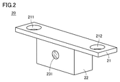
- FIG. 3 is a diagram illustrating an appearance of a vibration measurement unit according to the first embodiment.
- 3 is a functional block diagram for explaining a functional configuration of the vibration measurement system according to Embodiment 1.
- the vibration measuring system which concerns on Embodiment 1 it is a figure which shows a mode that a vibration measurement is performed avoiding the joint of a rail.
- 5 is a flowchart for explaining processing performed by a control unit of the vibration measurement unit according to the first embodiment.
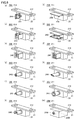
- FIG. 3 is a flowchart for illustrating a flow of processing performed in a control unit of the transmitter according to Embodiment 1. It is a figure which shows some examples of the light-shielding wall fixed to an accommodating part. It is a figure which shows a mode that the absorption wall is being fixed to the light-shielding wall. It is a figure which shows a mode that sunlight injected into the light-shielding wall.
- FIG. 10 is a diagram illustrating a state in which vibration measurement is performed while avoiding rail joints in the vibration measurement system according to the second embodiment. 10 is a flowchart showing a flow of processing performed by a control unit of a vibration measurement unit according to the second embodiment. It is an equivalent circuit diagram of the power supply unit of a comparative example.
- FIG. 10 is an equivalent circuit diagram of a power supply unit according to the third embodiment. It is a figure which shows an external view (a) of the battery holder with which a power supply unit is equipped, and a mode (b) with which the battery was mounted
- Fig. 11 shows a first modification of the battery holder according to the third embodiment.
- Fig. 11 is a diagram showing modifications 2 and 3 of the battery holder according to the third embodiment.
- Fig. 11 shows a fourth modification of the battery holder according to the third embodiment.
- FIG. 1 is a diagram illustrating a state in which a vibration measurement unit 20 according to an embodiment is fixed to a railway vehicle 10.
- the axle box 11 supports an axle bearing (not shown) attached to the axle 13.
- the axle box 11 is an object whose vibration is measured by the vibration measurement unit 20.
- Wheels 12 are attached to both ends of the axle 13 in the axial direction. Since the wheel 12 is rotatably supported by the axle bearing, the railway vehicle 10 can travel on the two rails 40 laid in parallel.
- the vibration measurement unit 20 is fastened to the axle box 11 with bolts 14. As the bolt 14, for example, a hexagonal bolt can be used.
- the vibration measurement unit 20 can measure the vibration of the axle bearing supported by the axle box 11 by being fixed to the axle box 11.
- the vibration measurement unit 20 starts vibration measurement by receiving the trigger signal.
- Each axle bearing can be inspected by temporarily fixing the vibration measurement unit to each axle box during maintenance inspection.
- whether the measured vibration is a vibration caused by an abnormality in the axle bearing, or the railcar determines, for example, a rail joint or branch point (point). It is necessary to distinguish whether the vibration is unrelated to the abnormality of the axle bearing, such as vibration generated when passing. Therefore, it is necessary to transmit the trigger signal so that the trigger signal is received by the vibration measurement unit in a place where vibration unrelated to the abnormality of the axle bearing is unlikely to occur.
- a method using radio waves can be cited as a method for transmitting a trigger signal.
- wireless communication using radio waves is difficult to attenuate because it has a large diffraction effect and is not easily blocked by obstacles. Therefore, when the trigger signal is transmitted to the vibration measurement unit using radio waves, the trigger signal may be received by the vibration measurement unit other than the transmission destination due to reflection or diffraction. In such a case, there is a possibility that the vibration measuring unit may measure the vibration in a place where vibration is irrelevant to the abnormality of the axle bearing such as a rail joint or a branch point. As a result, it may be difficult to accurately detect an abnormality in the axle bearing using the vibration data measured by the vibration measurement unit.
- the trigger signal is transmitted using infrared light.
- Infrared light having a frequency higher than that of radio waves has high straightness because the wavelength is shorter than that of radio waves. Infrared light is more likely to be blocked and attenuated by obstacles than radio waves. Therefore, it is difficult for the vibration measurement unit 20 other than the trigger signal transmission destination to receive the trigger signal. It becomes difficult for the vibration measurement unit to measure vibration in a place where vibration unrelated to the abnormality of the axle bearing is likely to occur. As a result, it is possible to improve the accuracy of detecting an abnormality in the axle bearing.
- FIG. 2 is a diagram illustrating an appearance of the vibration measurement unit 20 according to the first embodiment.
- the vibration measurement unit 20 includes a fixed portion 21 and a housing portion 22.
- Bolt holes 211 and 212 are formed in the fixing portion 21 at both ends in the longitudinal direction.
- the bolt holes 211 and 212 are holes for fastening the vibration measurement unit 20 to an object such as an axle box with bolts. By fastening the vibration measurement unit 20 to the object with a bolt, it is possible to reduce contact resonance that occurs regardless of the abnormality of the axle bearing on the contact surface between the vibration measurement unit 20 and the object.
- the housing part 22 is fixed to the fixed part 21.
- the accommodating part 22 accommodates and protects a control part, an infrared sensor, a vibration sensor, a memory
- a light receiving hole 231 for allowing the infrared sensor to receive infrared light is formed on the side surface of the housing portion 22.
- a lens is fixed to the light receiving hole 231.
- FIG. 3 is a functional block diagram for explaining the functional configuration of the vibration measurement system 100 according to the first embodiment.
- the vibration measurement system 100 includes a vibration measurement unit 20, a transmitter 30 that transmits infrared light, and an analysis device 400.
- the vibration measurement unit 20 receives the infrared light transmitted from the transmitter 30. Communication from the transmitter 30 to the vibration measurement unit 20 can be performed using infrared communication.
- the wavelength of the infrared light emitted from the transmitter 30 is, for example, 870 nm to 1000 nm.
- the infrared communication format is, for example, the NEC (registered trademark) format, the home-made cooperative (General Electric Appliances Association, AEHA (Association for Electric Home Appliances)) format, the SONY (registered trademark) format, or a similar original List formats.
- the transmitter 30 emits infrared light while turning on and off the intensity of infrared light at a carrier frequency of a predetermined frequency (for example, 30 kHz to 50 kHz). By modulating the emitted infrared light with the carrier frequency in this way, it is possible to emit infrared light having an intensity greater than the noise level while suppressing power required for emitting infrared light.
- the vibration measurement unit 20 includes a control unit 210, an infrared sensor 220 that is a light receiving element, a vibration sensor 230, a storage unit 240, and a power supply unit 250.
- Control unit 210 stores vibration data from vibration sensor 230 in storage unit 240 when the infrared light received by infrared sensor 220 is a trigger signal.
- the control unit 210 includes a computer such as a CPU (Central Processing Unit) and a volatile memory.
- the storage unit 240 includes a removable nonvolatile memory (not shown) such as an SD card or a USB (Universal Serial Bus) memory. Data stored in the storage unit 240 can be taken out by the nonvolatile memory.
- the storage unit 240 is an OS (Operating System) read out and executed by the control unit 210, various application programs (for example, a vibration measurement control program using infrared light as a trigger signal), and various types used by the programs. Save the data.
- the storage unit 240 may include, for example, a flash memory that is a nonvolatile semiconductor memory, or an HDD (Hard Disk Drive) that is a storage device.
- the power supply unit 250 includes a battery holder to which the battery 252 can be attached and detached.
- the power supply unit 250 supplies the power of the battery 252 to loads such as the control unit 210, the vibration sensor 230, and the storage unit 240.
- the analysis device 400 includes, for example, a PC (Personal Computer) on which vibration analysis software is installed.
- the analyzer 400 is equipped with a nonvolatile memory in which vibration data measured by the vibration measurement unit 20 is stored.
- the analysis device 400 reads vibration data from the nonvolatile memory and performs vibration analysis.
- FIG. 4 is a diagram illustrating a state in which the transmitter 30 transmits infrared light BM to the vibration measurement unit 20 in the vibration measurement system according to the first embodiment.
- the vibration measurement unit 20 receives a trigger signal from the transmitter 30, the vibration measurement unit 20 starts vibration measurement.
- the transmitter 30 is installed in a place where vibrations unrelated to the abnormality of the axle bearing are unlikely to occur. For example, it is a place near the measurement point on the rail where the vibration generated when the railway vehicle 10 passes through the joint or branch point of the rail is damped.
- the measurement point is separated from the rail joint or branch point by a predetermined distance.
- the predetermined distance can be appropriately calculated by an actual machine experiment or simulation.
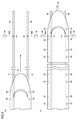
- FIG. 5 is a diagram illustrating a state in which vibration measurement is performed while avoiding rail joints in the vibration measurement system 100 according to the first embodiment.
- the measurement point P1 is separated from the point G where the rail joint exists by a predetermined distance.
- the transmitter 30 transmits an infrared light BM as a trigger signal toward the measurement point P1 on the rail.
- Each vibration measuring unit 20 shown in FIG. 5A sequentially passes through the point G as the railway vehicle 10 advances in the direction of the arrow. Thereafter, as shown in FIG. 5B, each vibration measurement unit 20 sequentially receives the trigger signal from the transmitter 30 when passing through the measurement point P1.
- the vibration measurement unit 20 stores the vibration data measured at the measurement time determined based on the timing at which the trigger signal is received in the storage unit 240.
- the measurement time determined based on the timing at which the trigger signal is received is a fixed time from the timing at which the trigger signal is received in the first embodiment.
- each vibration measurement unit 20 receives infrared light as a trigger signal at the measurement point P1.
- the vibration measurement unit 20 stores vibration data measured for a predetermined time from the timing when the trigger signal is received.
- the stored vibration data corresponding to each vibration measurement unit 20 is measured under almost the same conditions. For this reason, when comparing the vibration data of the axle bearings, there is no need to make corrections to make the measurement conditions uniform. As a result, since the difference between the vibration data indicating the abnormality of the axle bearing and the normal vibration data is clarified without requiring the correction, the abnormality of the axle bearing can be easily found.
- FIG. 6 is a flowchart for explaining processing performed by the control unit 210 of the vibration measurement unit 20 according to the first embodiment.
- the control unit 210 performs an initialization process in step (hereinafter, step is simply referred to as “S”) 201 and advances the process to step S ⁇ b> 202.
- the initialization process for example, the CPU and volatile memory included in the control unit 210 are initialized.
- the controller 210 determines whether or not a trigger signal has been received in S202. When the trigger signal is received (YES in S202), the vibration data measured by the vibration sensor 230 in S203 is stored in the storage unit 240, and the process returns to S202. If the trigger signal has not been received (NO in S202), the process proceeds to S204.
- the controller 210 determines whether or not a measurement end operation has been performed by the user in S204.
- the measurement end operation is, for example, a switch operation. When the measurement end operation has not been performed (NO in S204), control unit 210 returns the process to S202. If the measurement end operation has been performed (YES in S204), control unit 210 ends the process.
- FIG. 7 is a flowchart for illustrating a flow of processing performed in the control unit of transmitter 30 according to the first embodiment.
- the control unit of the transmitter 30 performs an initialization process in S301 and advances the process to S302.
- the control unit of the transmitter 30 transmits a trigger signal in S302, and the process proceeds to S303.
- the control unit of the transmitter 30 determines whether or not a transmission end operation has been performed by the user in S303.
- the transmission end operation is, for example, a switch operation. If the transmission end operation has not been performed by the user (NO in S303), the process returns to S302.
- the control unit of transmitter 30 ends the process.
- Embodiment 1 the case where communication from the transmitter 30 to the vibration measurement unit 20 is performed using infrared light has been described.
- the light used for communication from the transmitter 30 to the vibration measurement unit 20 is not limited to infrared light. Any light having a frequency higher than that of the radio wave can be used for transmitting a trigger signal from the transmitter 30 to the vibration measurement unit 20.
- infrared light is used as a trigger signal for starting measurement.
- Infrared light may be used as a trigger signal for the end of measurement.
- the vibration measurement unit may start measurement of vibration from a predetermined timing and continue measurement of vibration until a measurement end trigger signal is received.
- the measurement time determined based on the timing at which the trigger signal is received is the time from the predetermined timing until the trigger signal at the end of measurement is received.
- the vibration measurement unit stores vibration data measured in a measurement time determined based on a predetermined timing in the storage unit 240.
- the vibration measurement unit and the vibration measurement system according to the first embodiment it is possible to improve the accuracy of detecting an abnormality in an axle bearing.
- the light used as the trigger signal may be emitted from other than the transmitter.
- infrared light is included in sunlight. Sunlight is of little concern when measuring vibrations at night, in tunnels, or in facilities, or when measuring vibrations in cloudy or rainy weather.
- the input of the infrared sensor is saturated when sunlight enters the light receiving hole of the vibration measurement unit, and vibration measurement is performed. The unit may not be able to receive infrared or may malfunction.
- a description will be given of a modification in which a light shielding wall is provided around the light receiving hole so that light from other than the transmitter does not easily enter the light receiving hole of the vibration measurement unit.
- FIG. 8 is a diagram showing some examples of the light shielding wall fixed to the accommodating portion.
- FIGS. 8A to 8F are diagrams showing an example of a light shielding wall made of one or a plurality of plates.
- FIG. 8A is a diagram illustrating a light shielding wall 24A configured using a single plate. As shown in FIG. 8A, the normal line of the surface of the light shielding wall 24A facing the light receiving hole 231 is substantially parallel to the longitudinal direction of the fixed portion. The surface of the light shielding wall 24A facing the light receiving hole 231 is a wall surface close to the light receiving hole 231 among the wall surfaces of the light shielding wall 24A.
- the longitudinal direction of the fixed portion and the traveling direction of the railway vehicle to which the vibration measurement unit is fixed are substantially parallel.
- the longitudinal direction of the fixed portion is referred to as a traveling direction.
- FIG. 8 (b) is a diagram showing a light shielding wall 24B composed of a single plate.
- the normal line of the surface of the light shielding wall 24B facing the light receiving hole 231 is parallel to the direction in which the bolt is inserted into the bolt hole 211 or 212.
- the direction of the surface of the light shielding wall 24B facing the light receiving hole 231 is opposite to the direction in which the bolt is inserted into the bolt hole 211 or 212.
- the direction of the light shielding wall 24B facing the light receiving hole 231 may be substantially the same as the direction in which the bolt is inserted into the bolt hole 211 or 212.
- the direction in which the bolt is inserted into the bolt hole 211 or 212 is substantially the same as the direction from the rail to which the railway vehicle travels to the railway vehicle. And almost parallel.
- the direction in which the bolt is inserted into the bolt hole 211 or 212 is simply referred to as an insertion direction.
- FIG. 8 (c) and 8 (d) are diagrams showing an example of a light shielding wall in which a light receiving hole 231 is located between two opposing plates.
- the normal line of the surface of the light shielding wall 24C facing the light receiving hole 231 is substantially parallel to the traveling direction.
- FIG. 8D the normal line of the surface of the light shielding wall 24D facing the light receiving hole 231 is substantially parallel to the insertion direction.
- the normal line of the surface of the light-shielding wall facing the light-receiving hole 231 is not parallel to the traveling direction and not parallel to the insertion direction. Good.
- the two surfaces constituting the light shielding wall do not have to face each other.
- FIG. 8 (e) is a view showing a light shielding wall 24E composed of three plates.
- the three plates When the three plates are viewed from the direction of incidence of infrared light from the transmitter, the three plates form a U-shape. When the three plates are viewed from the direction of incidence of infrared light from the transmitter, the three plates may form a triangular shape.
- FIG. 8 (f) is a diagram showing a light shielding wall 24F composed of four plates.
- the four plates are fixed to the accommodating portion 22 so as to surround the light receiving hole 231 and form a rectangular or square shape when viewed from the incident direction of the infrared light from the transmitter.
- the four plates are not rectangular and have a non-square shape, such as a parallelogram or trapezoid. May be.
- the light shielding wall may be composed of five or more plates, and may have a polygonal shape when viewed from the direction of incidence of infrared light from the transmitter.
- the light-shielding wall may be composed of something other than a plate.
- the light shielding wall may be formed in a cylindrical shape like a light shielding wall 24G shown in FIG.
- the tip of the light shielding wall may be sharp like a light shielding wall 24H shown in FIG.
- the direction from the center of the light receiving hole 231 to the tip of the light shielding wall 24H is substantially the same as the insertion direction.
- the direction from the center of the light receiving hole 231 to the sharp tip of the light shielding wall may be a direction different from the insertion direction.
- a part of the side surface of the cylindrical shape may be open like a light shielding wall 24I shown in FIG. In the light shielding wall 24I, the open portion of the cylindrical side surface faces the direction opposite to the insertion direction. The direction of the part may not be opposite to the insertion direction.
- the light shielding wall may be formed of a truncated cone shape like a light shielding wall 24J shown in FIG.
- the light shielding wall 24J is formed in a truncated cone shape whose diameter decreases as the light receiving hole 231 is approached.
- the light shielding wall may be formed of a truncated cone shape whose diameter increases as it approaches the light receiving hole 231.
- a part of the side surface of the truncated cone shape may be opened.
- the open portion of the side surface of the truncated cone shape faces the direction opposite to the insertion direction. The direction of the part may not be opposite to the insertion direction.
- the light shielding wall may not be fixed to the outside of the accommodating portion, and may be accommodated in the accommodating portion 22M, for example, like the light shielding wall 24M as shown in FIG. A part of the light shielding wall may be accommodated in the accommodating portion.
- the color of the surface of the light shielding wall facing the light receiving hole 231 is black.
- the sunlight incident on the surface is absorbed by the surface, so that the sunlight can be prevented from being reflected by the surface and entering the light receiving hole 231.
- light from other than the transmitter is less likely to enter the light receiving hole 231 of the vibration measurement unit, and the accuracy of detecting an abnormality in the axle bearing can be further improved.
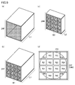
- FIG. 9 is a diagram illustrating a state where the absorption wall is fixed to the light shielding wall.
- the appearance of the absorption wall will be described by taking as an example the case where the absorption wall is fixed to the light shielding wall 24F shown in FIG. Fig.9 (a) is a figure which shows the light-shielding wall 24F of FIG.8 (f).
- FIG. 9B is a diagram illustrating a state where the absorption wall W1 is fixed to the light shielding wall 24F.
- FIG. 9C is a diagram illustrating a state in which the absorption wall W2 is fixed to the light shielding wall 24N in which the length of the light shielding wall 24F is shortened in the depth direction.
- FIG. 9D is a diagram illustrating a state in which the absorption walls W1 and W2 are viewed from the depth direction.
- the depth direction is an incident direction of the infrared light emitted from the transmitter to the light receiving hole 231.
- the depth direction is the same as the normal direction of the surface in which the light receiving hole is formed in the housing portion of the vibration measurement unit.
- the absorption walls W1 and W2 are fixed so as to divide the light receiving hole 231 into a plurality of regions R11 to R44.
- the surfaces of the absorption walls W1 and W2 facing each of the plurality of regions R11 to R44 are along the depth direction.
- the color of the surface is black.
- the absorption walls W1 and W2 have a lattice-like honeycomb structure that divides the light receiving holes 231 into rectangular or square holes having substantially the same shape when viewed from the depth direction.
- the length of the light shielding wall 24F and the absorption wall W1 in the depth direction is L1.
- the length of the light shielding wall 24N and the absorption wall W2 in the depth direction is L2 ( ⁇ L1).
- FIG. 10 is a diagram showing a state in which sunlight is incident on the light shielding wall.
- Fig.10 (a) is a figure which shows a mode that sunlight injected into the light-shielding wall 24F of Fig.9 (a).
- FIG.10 (b) is a figure which shows a mode that sunlight injected into the light-shielding wall 24F of FIG.9 (b).
- FIG.10 (c) is a figure which shows a mode that sunlight injected into the light shielding wall 24N of FIG.9 (c). The effect of the light shielding wall will be described with reference to FIG.
- the vibration measurement unit may not be able to receive infrared rays or may malfunction.
- the length of the light shielding wall in the depth direction can be made shorter than when the absorbing wall is not used while maintaining the accuracy of detecting the abnormality of the axle bearing.
- the light receiving hole 231 is separated from the point where the sunlight SL1 to SL3 hits the absorption wall W1 and the point where the sunlight SL4 hits the light shielding wall 24N by a length L10.
- the sunlight SL1 to SL4 can be prevented from entering the light receiving hole 231.
- the light blocking walls 24N and the absorbing walls W2 can also prevent the sunlight SL1 to SL4 from entering the light receiving holes 231 similarly to FIG. 10B.
- the absorption wall is used in this way, the length in the depth direction of the light shielding wall and the absorption wall can be made shorter than the case where the absorption wall is not used. Therefore, the manufacturing cost of the vibration measurement unit by adding the absorption wall Can be suppressed.
- the case where the measurement time determined based on the timing at which the trigger signal is received is a fixed time from the timing at which the trigger signal is received in the first embodiment.
- the measurement time determined based on the timing at which the trigger signal is received is a fixed period from the timing at which a predetermined time has elapsed since the vibration measurement unit received the trigger signal.
- the second embodiment is different from the first embodiment in that vibration data measured during a predetermined period from the timing when the vibration measurement unit receives a trigger signal and a predetermined time elapses is stored. Since the other points are the same as in the first embodiment, the description will not be repeated.
- FIG. 11 is a diagram illustrating a state in which vibration measurement is performed while avoiding rail joints in the vibration measurement system according to the second embodiment.
- the measurement point P1 is separated from the point G where the rail joint exists by a predetermined distance.
- the transmitter 30 emits infrared light as a trigger signal toward the point G.
- Each vibration measurement unit 20N shown in FIG. 11A sequentially receives trigger signals when passing the point G as the railway vehicle 10 advances in the direction of the arrow. Thereafter, when the railway vehicle 10 travels at a speed approximately equal to the speed obtained by dividing the distance between the point G and the measurement point P1 by a predetermined time, as shown in FIG. Vibration data measured in the vicinity of the measurement point P1 that passes after a predetermined time has elapsed is stored in the storage unit 240.
- each vibration measurement unit 20N stores vibration data measured in the vicinity of the measurement point P1.
- the stored vibration data corresponding to each vibration measurement unit 20N is measured under almost the same conditions. For this reason, when comparing the vibration data of the axle bearings, there is no need to make corrections to make the measurement conditions uniform. As a result, since the difference between the vibration data indicating the abnormality of the axle bearing and the normal vibration data is clarified without requiring the correction, the abnormality of the axle bearing can be easily found.
- FIG. 12 is a flowchart showing a flow of processing performed by the control unit of vibration measurement unit 20N according to the second embodiment.
- the control unit of the vibration measurement unit 20N performs an initialization process in S201 and advances the process to S202.
- the control unit of the vibration measurement unit 20N determines whether or not a trigger signal is received in S202.
- the control unit of vibration measurement unit 20N waits for a predetermined time in S213 and advances the process to S203.
- the vibration data measured by the vibration sensor 230 in S203 is stored in the storage unit 240, and the process returns to S202. If the trigger signal has not been received (NO in S202), the process proceeds to S204.
- the control unit of the vibration measurement unit 20N determines whether or not a measurement end operation has been performed by the user in S204.
- the measurement end operation is, for example, a switch operation. When the measurement end operation has not been performed (NO in S204), the control unit of vibration measurement unit 20N returns the process to S202. If the measurement end operation has been performed (YES in S204), the control unit of vibration measurement unit 20N ends the process.
- the vibration measurement unit and the vibration measurement system according to the second embodiment it is possible to improve the accuracy of detection of an abnormality in an axle bearing as in the first embodiment.
- the battery holder that holds the battery 252 included in the power supply unit 250 of FIG. 3 includes a coil spring that is an elastic body as a conductor that contacts the electrode of the battery.
- the coil spring is elastically deformed when the battery 252 is attached to the battery holder and applies an elastic force to the battery 252 to maintain contact between each electrode of the battery 252 and each conductor of the battery holder.
- the battery holder is fixed to the vibration measurement unit 20 and used in an environment where vibration occurs. If the contact between the electrode of the battery 252 and the conductor of the battery holder is momentarily released due to elastic deformation of the coil spring due to vibration, power is not supplied from the power supply unit 250.
- FIG. 13 is an equivalent circuit diagram of the power supply unit 950 of the comparative example.
- the battery 252 is electrically connected between the positive terminal P and the negative terminal N, but the power storage device is not connected.
- FIG. 14 is a graph (a) showing a change in voltage output from the power supply unit 950 of the comparative example and a graph (b) showing a change in voltage of the load C.
- Figure 14 (a) and (b) at time t 1 is in contact with the battery electrodes and the conductor off momentarily in poor contact is continued until time t 2.
- the voltage output from the power source unit is lower than the time t 1 earlier.
- control unit 210 When such a momentary power interruption occurs intermittently with vibration, the control unit 210, the vibration sensor 230, the storage unit 240, and the like to which power is supplied from the battery 252 attached to the battery holder are unstable. There is a risk of becoming.
- the power storage device is electrically connected in parallel with the battery between the positive terminal P and the negative terminal N of the battery holder.
- FIG. 15 is an equivalent circuit diagram of power supply unit 250 according to the third embodiment. As shown in FIG. 15, power supply unit 250 includes one or more batteries 252, power storage device 254, positive electrode terminal P, and negative electrode terminal N.
- the positive electrode terminal P is electrically connected to the positive electrode of the battery 252.
- the negative terminal N is electrically connected to the negative electrode of the battery 252.
- the electric power of the battery 252 is taken out from the positive terminal P and the negative terminal N and supplied to the load C.
- the power storage device 254 is electrically connected in parallel to the battery 252 between the positive terminal P and the negative terminal N.
- the power storage device 254 preferably includes an electric double layer capacitor (EDLC).
- EDLC electric double layer capacitor
- the electric double layer capacitor has a larger capacity than other capacitors.
- the electric double layer capacitor has a faster charge / discharge speed than the secondary battery and is less deteriorated by charge / discharge.
- the electric double layer capacitor is suitable for a backup power source at the momentary power failure.
- the power storage device 254 can include various capacitors such as an aluminum electrolytic capacitor, a ceramic capacitor, and a film capacitor, or a secondary battery.
- FIG. 16 shows an external view (a) of the battery holder 300 provided in the power supply unit 250 and a state (b) in which the battery 252 is attached to the battery holder 300.
- the battery holder 300 includes a positive electrode terminal P, a negative electrode terminal N, a plurality of conductor pairs 301 and 302, a power storage device 254, and a power storage container 307.
- the conductor pair 301 includes a first conductor 301A and a second conductor 301B.
- the second conductor 301B has a coil spring that is an elastic body. As shown in FIG. 16B, the first conductor 301A and the second conductor 301B hold the battery 252A sandwiched from both sides in the longitudinal direction.
- the second conductor 301B maintains the contact between the first conductor 301A and the electrode of the battery 252A by applying an elastic force toward the first conductor 301A, and the battery between the first conductor 301A and the second conductor 301B. Hold 252A.
- the conductor pair 302 includes a first conductor 302A and a second conductor 302B.
- the second conductor 302B has a coil spring that is an elastic body. As shown in FIG. 16B, the first conductor 302A and the second conductor 302B hold the battery 252B sandwiched from both sides in the longitudinal direction. The second conductor 302B maintains the contact between the first conductor 302A and the electrode of the battery 252B by applying an elastic force toward the first conductor 302A, and the battery between the first conductor 302A and the second conductor 302B. 252B is held.
- the positive terminal P is electrically connected to the first conductor 302A.
- the negative terminal N is electrically connected to the second conductor 301B.
- the first conductor 301A is electrically connected to the second conductor 302B.
- the conductor pair 301 and the conductor pair 302 electrically connect two batteries 252A and 252B in series.
- the power storage device 254 is electrically connected to the positive terminal P and the negative terminal N and is fixed to the battery holder 300.
- the power storage device 254 vibrates integrally with the battery holder 300 by being fixed to the battery holder 300.
- the power storage device 254 is electrically connected in parallel with the batteries 252A and 252B electrically connected in series between the positive terminal P and the negative terminal N when the batteries 252A and 252B are attached to the power supply unit 250. Has been.
- the power storage device 254 is stored in the power storage container 307.
- the power storage device 254 is charged by the power from the batteries 252A and 252B when the batteries 252A and 252B are attached to the battery holder 300 and power is supplied from the batteries 252A and 252B to the load.
- FIG. 17 is a diagram illustrating a state where the contact between the first conductor 301A and the battery 252A is instantaneously released due to vibration.
- FIG. 18 is a graph (a) showing changes in the voltage output from the power supply unit 250 and a graph (b) showing changes in the voltage of the load C.
- the contact between the battery electrode and the conductor as shown in FIG. 17 is disengaged instantaneously at time t 11, the contact failure is continued until time t 2.
- FIG. 18 (a) between the time t 11 to t 12, reduction in the voltage output from the power supply unit 250, from the voltage drop in the comparative example that is shown in FIG. 14 (a) Is also suppressed. This is because power is supplied from the power storage device 254 instead of the batteries 252A and 252B.
- FIG. 18 (b) between the time t 11 to t 12, the voltage of the load does not substantially decrease.
- the power supply unit 250 it is possible to stably supply power in an environment in which vibrations occur, and to reduce costs.
- FIG. 19 shows a first modification of the battery holder according to the third embodiment.
- the case where the second conductor of the battery holder has a coil spring as an elastic body has been described above.
- the elastic body included in the second conductor is not limited to the coil spring.
- the elastic body included in the second conductor may be a leaf spring, such as second conductors 311B and 312B included in the battery holder 310 shown in FIG.
- FIG. 20 is a diagram showing modifications 2 and 3 of the battery holder according to the third embodiment.
- the number of conductor pairs included in the power supply holder may be one as in the second modification shown in FIG. 20 (a) or three or more as in the third modification shown in FIG. 20 (b). Good.
- FIG. 21 shows a fourth modification of the battery holder according to the third embodiment.
- the number of batteries held by the conductor pair may be two or more like the conductor pairs 341 and 342 shown in FIG.
- the conductor pair 341 holds two batteries sandwiched from both sides in the longitudinal direction.
- the second conductor 341B including a coil spring that is an elastic body holds the two batteries 252A and 252B between the first conductor 341A and the second conductor 341B by applying an elastic force toward the first conductor 341A. .
- the conductor pair 342 holds the batteries 252C and 252D.
- the power supply unit according to the present invention is used for a vibration measurement unit that measures vibration of an axle bearing of a railway vehicle.
- the battery holder according to the present invention is not limited to the vibration measurement unit for the axle bearing of a railway vehicle.
- the power supply unit according to the present invention can be used as a power supply for equipment used in an environment in which vibrations occur, for example, as a power supply for equipment installed in automobiles, light vehicles, construction vehicles, agricultural vehicles, and industrial vehicles. It can be used.
Landscapes
- Chemical & Material Sciences (AREA)
- Chemical Kinetics & Catalysis (AREA)
- Electrochemistry (AREA)
- General Chemical & Material Sciences (AREA)
- Engineering & Computer Science (AREA)
- Aviation & Aerospace Engineering (AREA)
- Physics & Mathematics (AREA)
- General Physics & Mathematics (AREA)
- Measurement Of Mechanical Vibrations Or Ultrasonic Waves (AREA)
Abstract
車軸軸受の異常検知の精度を向上させる。本発明に係る振動測定ユニット(20)は、対象物(10)に固定されて使用される。振動測定ユニット(20)は、振動センサと、受光素子と、記憶部とを備える。振動センサは、対象物(10)の振動データを測定するように構成される。受光素子は、送信器(30)からの光(BM)を受けるように構成される。記憶部は、振動データが保存されるように構成される。記憶部は、受光素子が光(BM)を受けたタイミングに基づいて決定される測定時間において測定された振動データを記憶するように構成される。
Description
この発明は、鉄道車両における車軸軸受の異常の検知のための振動測定に用いられる振動測定ユニット、振動測定システム、および振動測定方法に関する。
鉄道車両において車軸軸受に異常が発生した場合、脱線などの事故が発生する可能性が高まるため、そのまま走行を継続することは好ましくない。そのような場合には、車両の運転を停止して、車軸軸受の補修などの処置が必要となる。
車軸軸受の補修には長時間を要する場合がある。通常運転の長時間の停止には多大な損失が発生し得る。そのため、通常運転に備えて行なわれる保守点検において、車軸軸受に異常がないかどうかを検査することがある。
車軸軸受の異常を診断する方法として、車軸軸受に振動測定ユニットを固定して振動を測定することにより、車軸軸受に発生した異常を検知する方法が知られている。しかし、この方法には、測定された振動が車軸軸受の異常に起因する振動なのか、あるいは鉄道車両がたとえばレールの継ぎ目あるいは分岐点(ポイント)を通過したときに生じた振動のような車軸軸受の異常とは無関係の振動なのかを区別できないという問題がある。
このような問題を解決する手段として、特開2015-172516号公報(特許文献1)には、レールの継ぎ目あるいは分岐点のない地点において振動の測定を行なった振動測定ユニットから後続する振動測定ユニットに遅延時間へ設けてトリガ信号を無線通信によって順次送信することにより、レールの継ぎ目あるいは分岐点を避けて振動測定を行なう鉄道車両用軸受異常検知装置が開示されている。
特開2015-172516号公報において開示されている振動測定ユニット間の無線通信は電波を用いて行なわれる。以下では、電波は300万メガヘルツ(3テラヘルツ)以下の周波数の電磁波とする。電波は、回折の効果が大きく障害物によって遮られにくいため伝搬距離が長い。
振動測定ユニット間の通信を電波を用いて行なうと、反射あるいは回折によって、送信先以外の振動測定ユニットにもトリガ信号が受信されてしまう場合がある。そのような場合、レールの継ぎ目あるいは分岐点のある地点において振動が測定され得る。その結果、車軸軸受の異常の検知を正確に行なうことが困難になる可能性がある。
本発明はこのような課題を解決するためになされたものであって、本発明の主たる目的は、車軸軸受の異常検知の精度を向上させることである。
本発明に係る振動測定ユニットは、対象物に固定されて使用される。振動測定ユニットは、振動センサと、受光素子と、記憶部とを備える。振動センサは、対象物の振動データを測定するように構成される。受光素子は、送信器からの光を受けるように構成される。記憶部は、振動データが保存されるように構成される。記憶部は、受光素子が光を受けたタイミングに基づいて決定される測定時間において測定された振動データを記憶するように構成される。
本発明に係る振動測定ユニット、振動測定システム、および振動測定方法によれば、電波よりも回折しにくく、減衰し易い光をトリガ信号として用いることにより、送信先以外の振動測定ユニットにトリガ信号が受信され難くなるため、意図しないタイミングで振動が測定されることを抑制することができる。その結果、車軸軸受の異常検知の精度を向上させることができる。
以下、図面を参照しつつ、実施の形態について説明する。なお、以下の説明では、同一又は対応する要素には同一の符号を付して、それらについての詳細な説明は繰り返さない。
[実施の形態1]
図1は、実施の形態に係る振動測定ユニット20が鉄道車両10に固定されている様子を示す図である。軸箱11は、車軸13に取り付けられる車軸軸受(不図示)を支持する。軸箱11は、振動測定ユニット20によって振動が測定される対象物である。車軸13の軸方向の両端部に車輪12がそれぞれ取り付けられる。車輪12が車軸軸受により回転自在に支持されることにより、鉄道車両10は平行に敷設された2本のレール40上を走行することができる。振動測定ユニット20は、軸箱11にボルト14によって締結されている。ボルト14としては、たとえば六角ボルトを用いることができる。振動測定ユニット20は、軸箱11に固定されていることにより、軸箱11が支持する車軸軸受の振動を測定することができる。振動測定ユニット20は、トリガ信号を受信することにより振動測定を開始する。
図1は、実施の形態に係る振動測定ユニット20が鉄道車両10に固定されている様子を示す図である。軸箱11は、車軸13に取り付けられる車軸軸受(不図示)を支持する。軸箱11は、振動測定ユニット20によって振動が測定される対象物である。車軸13の軸方向の両端部に車輪12がそれぞれ取り付けられる。車輪12が車軸軸受により回転自在に支持されることにより、鉄道車両10は平行に敷設された2本のレール40上を走行することができる。振動測定ユニット20は、軸箱11にボルト14によって締結されている。ボルト14としては、たとえば六角ボルトを用いることができる。振動測定ユニット20は、軸箱11に固定されていることにより、軸箱11が支持する車軸軸受の振動を測定することができる。振動測定ユニット20は、トリガ信号を受信することにより振動測定を開始する。
鉄道車両において車軸軸受に異常が発生した場合、脱線などの事故が発生する可能性が高まるため、そのまま走行を継続することは好ましくない。車両の運転を停止して、車軸軸受の補修などの処置が必要となる。
車軸軸受の補修には長時間を要する場合がある。通常運転の長時間の停止には多大な損失が発生し得る。そのため、通常運転に備えて行なわれる保守点検において、車軸軸受に異常がないかどうかを検査することがある。
保守点検時に各軸箱に振動測定ユニットを一時的に固定することにより、各車軸軸受の検査を行なうことができる。振動測定ユニットによって測定された振動データを用いて振動解析を行なうにあたっては、測定された振動が車軸軸受の異常に起因する振動なのか、あるいは鉄道車両がたとえばレールの継ぎ目または分岐点(ポイント)を通過したときに生じた振動のような車軸軸受の異常とは無関係の振動なのかを区別する必要がある。そのため、車軸軸受の異常とは無関係の振動が発生しにくい場所においてトリガ信号が振動測定ユニットに受信されるようにトリガ信号を送信する必要がある。
トリガ信号を送信する方法として電波を用いる方法を挙げることができる。しかし、電波を使用した無線通信は、回折の効果が大きく障害物によって遮られにくいため減衰しにくい。そのため、電波を用いてトリガ信号を振動測定ユニットへ送信すると、反射あるいは回折によって、送信先以外の振動測定ユニットにもトリガ信号が受信されてしまう場合がある。そのような場合、レールの継ぎ目または分岐点のような車軸軸受の異常とは無関係の振動が発生し易い場所において振動測定ユニットが振動を測定してしまう可能性がある。その結果、振動測定ユニットによって測定された振動データを用いて車軸軸受の異常の検知を正確に行なうことが困難になる可能性がある。
そこで実施の形態1においては、トリガ信号を赤外光を用いて送信する。電波よりも周波数が高い赤外光は、電波よりも波長が短いため直進性が高い。赤外光は電波よりも障害物によって遮られ易く減衰し易い。そのため、トリガ信号の送信先以外の振動測定ユニット20に当該トリガ信号が受信されにくい。車軸軸受の異常とは無関係の振動が発生し易い場所において振動測定ユニットが振動を測定することが発生し難くなる。その結果、車軸軸受の異常の検知の精度を向上させることができる。
図2は、実施の形態1に係る振動測定ユニット20の外観を示す図である。振動測定ユニット20は、固定部21と収容部22とを備える。固定部21には、長手方向の両端にそれぞれボルト孔211および212が形成されている。ボルト孔211および212孔は、ボルトによって振動測定ユニット20を軸箱などの対象物に締結するための孔である。ボルトによって振動測定ユニット20を対象物に締結することにより、振動測定ユニット20と対象物との接触面において車軸軸受の異常とは無関係に発生する接触共振を軽減することができる。
収容部22は、固定部21に固定されている。収容部22は、制御部、赤外線センサ、振動センサ、記憶部、および電源ユニットなどを収容して保護する。収容部22の側面には、赤外線センサが赤外光を受光することができるようにするための受光孔231が形成されている。受光孔231には、レンズが固定されている。
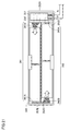
実施の形態においては、上記で説明した振動測定ユニット20に加えて、振動測定ユニット20に赤外光を出射するための送信器、および振動測定ユニット20によって測定された振動データを解析するための解析装置を含む振動測定システムによって、車軸軸受の異常の検知を行なう。図3は、実施の形態1に係る振動測定システム100の機能構成を説明するための機能ブロック図である。図3に示されるように、振動測定システム100は、振動測定ユニット20と、赤外光を送信する送信器30と、解析装置400とを備える。
振動測定ユニット20は、送信器30から送信された赤外光を受信する。送信器30から振動測定ユニット20への通信は、赤外線通信を用いて行なうことができる。送信器30が出射する赤外光の波長は、たとえば870nm~1000nmである。赤外線通信のフォーマットは、たとえばNEC(登録商標)フォーマット、家製協(一般財団法人家電製品協会、AEHA(Association for Electric Home Appliances))フォーマット、SONY(登録商標)フォーマット、またはこれらに類似した独自のフォーマットを挙げることができる。送信器30においては、所定の周波数(たとえば30kHzから50kHz)のキャリア周波数で赤外光の強度をON・OFFしながら赤外光を出射する。このように出射する赤外光をキャリア周波数で変調することにより、赤外光の出射に必要な電力を抑制しながらノイズのレベルよりも大きい強度の赤外光を出射することができる。
振動測定ユニット20は、制御部210と、受光素子である赤外線センサ220と、振動センサ230と、記憶部240と、電源ユニット250とを備える。
制御部210は、赤外線センサ220が受信した赤外光がトリガ信号である場合、振動センサ230からの振動データを記憶部240に保存する。制御部210は、CPU(Central Processing Unit)のようなコンピュータおよび揮発性メモリを含む。
記憶部240は、たとえばSDカードあるいはUSB(Universal Serial Bus)メモリのような着脱可能な不揮発性メモリ(不図示)を含む。記憶部240に保存されたデータは、当該不揮発性メモリによって取り出すことができる。記憶部240は、制御部210に読み出されて実行されるOS(Operating System)、各種アプリケーションのプログラム(たとえば赤外光をトリガ信号とする振動測定制御プログラム)、および当該プログラムによって使用される各種データを保存する。記憶部240は、たとえば、不揮発性の半導体メモリであるフラッシュメモリ、または記憶装置であるHDD(Hard Disk Drive)を含んでもよい。
電源ユニット250は、電池252を着脱可能な電池ホルダを含む。電源ユニット250は、電池252の電力を制御部210、振動センサ230、および記憶部240のような負荷に供給する。
解析装置400は、たとえば振動解析ソフトウェアがインストールされたPC(Personal Computer)を含む。解析装置400には、振動測定ユニット20によって測定された振動データが保存された不揮発性メモリが装着される。解析装置400は、当該不揮発性メモリから振動データを読み込んで振動解析を行なう。
図4は、実施の形態1に係る振動測定システムにおいて、送信器30が振動測定ユニット20に赤外光BMを送信している様子を示す図である。図4に示されるように振動測定ユニット20は、送信器30からのトリガ信号を受信した場合、振動測定を開始する。送信器30は、車軸軸受の異常とは無関係の振動が発生し難い場所に設置される。たとえば、鉄道車両10がレールの継ぎ目あるいは分岐点を通過したときに発生する振動がほとんど減衰しているレール上の測定点付近の場所である。当該測定点は、レールの継ぎ目あるいは分岐点から所定の距離だけ離れている。当該所定の距離は、実機実験あるいはシミュレーションによって適宜算出することができる。
図5は、実施の形態1に係る振動測定システム100において、レールの継ぎ目を避けて振動測定が行なわれる様子を示す図である。図5において測定点P1はレールの継ぎ目がある地点Gから所定の距離だけ離れている。送信器30はレール上の測定点P1に向けてトリガ信号である赤外光BMを送信する。図5(a)に示される各振動測定ユニット20は、鉄道車両10が矢印方向に進んでいくにつれて、順次地点Gを通過していく。その後、図5(b)に示されるように、各振動測定ユニット20は、測定点P1を通過するときに送信器30からのトリガ信号を順次受信する。振動測定ユニット20は、トリガ信号を受信したタイミングに基づいて決定される測定時間に測定された振動データを記憶部240に保存する。トリガ信号を受信したタイミングに基づいて決定される測定時間とは、実施の形態1においてはトリガ信号を受信したタイミングから一定時間である。
図5(b)に示されるように、各振動測定ユニット20は測定点P1においてトリガ信号としての赤外光を受ける。実施の形態1においては、振動測定ユニット20は、トリガ信号を受信したタイミングから一定時間の間に測定された振動データを保存する。各振動測定ユニット20に対応する保存された振動データは、ほとんど同条件で測定されたものになる。そのため、各車軸軸受の振動データの比較を行なう場合に、測定条件をそろえるための補正を行なう必要がない。その結果、当該補正を要することなく車軸軸受の異常を示す振動データと正常な振動データとの差異が明確になるため、車軸軸受の異常の発見が容易になる。
図6は、実施の形態1に係る振動測定ユニット20の制御部210によって行なわれる処理を説明するためのフローチャートである。図6に示されるように、制御部210は、ステップ(以下ではステップを単にSと記載する。)201において初期化処理を行ない処理をS202に進める。初期化処理においては、たとえば制御部210に含まれるCPUおよび揮発性メモリなどの初期化が行なわれる。制御部210は、S202においてトリガ信号を受信したか否かを判定する。トリガ信号を受信した場合(S202においてYES)、S203において振動センサ230によって測定された振動データを記憶部240に保存し、処理をS202に戻す。トリガ信号を受信していない場合(S202においてNO)、処理をS204に進める。制御部210は、S204においてユーザによって測定終了操作が行なわれたか否かを判定する。測定終了操作としては、たとえばスイッチ操作である。測定終了操作が行なわれていない場合(S204においてNO)、制御部210は処理をS202に戻す。測定終了操作が行なわれていた場合(S204においてYES)、制御部210は処理を終了する。
図7は、実施の形態1に係る送信器30の制御部において行なわれる処理の流れを示すためのフローチャートである。図7に示されるように送信器30の制御部はS301において初期化処理を行ない処理をS302に進める。送信器30の制御部はS302においてトリガ信号を送信し、処理をS303に進める。送信器30の制御部はS303においてユーザによって送信終了操作が行なわれたか否かを判定する。送信終了操作は、たとえばスイッチ操作である。ユーザによって送信終了操作が行なわれていない場合(S303においてNO)、処理をS302に戻す。ユーザによって送信終了操作が行なわれた場合(S303においてYES)、送信器30の制御部は処理を終了する。
実施の形態1においては、送信器30から振動測定ユニット20への通信は赤外光を用いて行なわれる場合について説明した。送信器30から振動測定ユニット20への通信に用いられる光は赤外光に限定されない。電波よりも周波数が高い光であれば送信器30から振動測定ユニット20へのトリガ信号の送信に使用することができる。
実施の形態1においては、赤外光は、測定開始のトリガ信号として用いられる。赤外光は、測定終了のトリガ信号として用いられてもよい。たとえば、振動測定ユニットは、所定のタイミングから振動の測定を開始、測定終了のトリガ信号受信するまで振動の測定を継続してもよい。この場合、トリガ信号を受信したタイミングに基づいて決定される測定時間とは、所定のタイミングから測定終了のトリガ信号を受信するまでの時間である。振動測定ユニットは、所定のタイミングに基づいて決定される測定時間において測定された振動データを記憶部240に保存する。
以上、実施の形態1に係る振動測定ユニットおよび振動測定システムによれば、車軸軸受の異常の検知の精度を向上させることができる。
[実施の形態1の変形例]
トリガ信号として用いる光が、送信器以外から出射される場合がある。たとえば、実施の形態1では振動データを保存するトリガ信号として赤外光を用いる場合について説明した。赤外光は太陽光に含まれる。夜間、トンネル内、または施設内での振動測定、あるいは天候が曇りまたは雨天での振動測定を行なう場合は太陽光はほとんど問題にならない。しかし、天候が晴れている昼間の屋外のような太陽光が無視できない状態で振動測定を行なう場合、太陽光が振動測定ユニットの受光孔に入射することにより赤外線センサの入力が飽和し、振動測定ユニットが赤外線を受信することができなくなったり、誤動作したりする可能性がある。
トリガ信号として用いる光が、送信器以外から出射される場合がある。たとえば、実施の形態1では振動データを保存するトリガ信号として赤外光を用いる場合について説明した。赤外光は太陽光に含まれる。夜間、トンネル内、または施設内での振動測定、あるいは天候が曇りまたは雨天での振動測定を行なう場合は太陽光はほとんど問題にならない。しかし、天候が晴れている昼間の屋外のような太陽光が無視できない状態で振動測定を行なう場合、太陽光が振動測定ユニットの受光孔に入射することにより赤外線センサの入力が飽和し、振動測定ユニットが赤外線を受信することができなくなったり、誤動作したりする可能性がある。
そこで、以下では、振動測定ユニットの受光孔に送信器以外からの光が入射し難くなるように、受光孔の周囲に遮光壁を設ける変形例について説明する。受光孔の周囲に遮光壁を設けることによって、振動測定ユニットを安定的に動作させることができる。
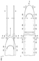
図8は、収容部に固定される遮光壁のいくつかの例を示す図である。遮光壁は、図8(a)~(f)は、1または複数の板から構成されている遮光壁の例を示す図である。図8(a)は、1枚の板を用いて構成されている遮光壁24Aを示す図である。図8(a)に示されるように、受光孔231に面する遮光壁24Aの面の法線は固定部の長手方向にほぼ平行である。受光孔231に面する遮光壁24Aの面とは、遮光壁24Aの壁面のうち、受光孔231に近い壁面である。実施の形態において、固定部の長手方向と、振動測定ユニットが固定される鉄道車両の進行方向とはほぼ平行である。以下では、固定部の長手方向を走行方向と呼ぶ。
図8(b)は、1枚の板から構成されている遮光壁24Bを示す図である。図8(b)に示されるように、受光孔231に面する遮光壁24Bの面の法線はボルト孔211または212にボルトを挿通する方向と平行である。受光孔231に面する遮光壁24Bの面の向きは、ボルト孔211または212にボルトを挿通する方向とは逆である。受光孔231に面する遮光壁24Bの面の向きは、ボルト孔211または212にボルトを挿通する方向とほぼ同じであってもよい。実施の形態において、ボルト孔211または212にボルトを挿通する方向は、振動測定ユニットが鉄道車両に固定された場合、鉄道車両が走行するレールから鉄道車両への方向とほぼ同じになり、鉛直方向とほぼ平行となる。以下ではボルト孔211または212にボルトを挿通する方向を単に挿通方向と呼ぶ。
図8(c)および(d)は、対向する2枚の板の間に受光孔231が位置している遮光壁の例を示す図である。図8(c)に示されているように、受光孔231に面する遮光壁24Cの面の法線は走行方向にほぼ平行である。図8(d)に示されるように、受光孔231に面する遮光壁24Dの面の法線は挿通方向にほぼ平行である。対向する2枚の板の間に受光孔231が位置している遮光壁において、受光孔231に面する遮光壁の面の法線は、走行方向に平行でなく、かつ挿通方向と平行でなくてもよい。遮光壁を構成する2枚の面は対向していなくてもよい。
図8(e)は、3枚の板から構成されている遮光壁24Eを示す図である。当該3枚の板を送信器からの赤外光の入射方向から見た場合、当該3枚の板はU字状の形状を形成している。当該3枚の板を送信器からの赤外光の入射方向から見た場合に、当該3枚の板は三角形の形状を形成してもよい。
図8(f)は、4枚の板から構成されている遮光壁24Fを示す図である。当該4枚の板は、受光孔231を囲むように収容部22に固定されており、送信器からの赤外光の入射方向から見た場合に矩形または正方形の形状を形成している。当該4枚の板を送信器からの赤外光の入射方向から見た場合に、たとえば平行四辺形あるいは台形のような、当該4枚の板が矩形でなく、かつ正方形でない形状を形成していてもよい。
遮光壁は、5枚以上の板から構成され、送信器からの赤外光の入射方向から見た場合に多角形の形状を形成していてもよい。
遮光壁は、板以外のものから構成されていてもよい。遮光壁は、たとえば図8(g)に示される遮光壁24Gのように円筒状の形状から構成されていてもよい。遮光壁の先端部は、図8(h)に示される遮光壁24Hのように、尖っていてもよい。送信機からの赤外光の入射方向から見た場合、受光孔231の中心から遮光壁24Hの先端部への方向は挿通方向とほぼ同じである。受光孔231の中心から遮光壁の尖っている先端部への方向は、挿通方向とは異なる方向であってもよい。図8(i)に示される遮光壁24Iのように、円筒状の形状の側面の一部が開いていてもよい。遮光壁24Iにおいて、円筒状の形状の側面の開いている部分は挿通方向とは逆方向を向いている。当該部分の向きは挿通方向と逆でなくてもよい。
遮光壁は、図8(j)に示される遮光壁24Jのように、円錐台状の形状から構成されていてもよい。遮光壁24Jは、受光孔231に近づくにつれて径が小さくなる円錐台状の形状から構成されている。遮光壁は、受光孔231に近づくにつれて径が大きくなる円錐台状の形状から構成されてもよい。図8(k)に示される遮光壁24Kのように、円錐台状の形状の側面の一部が開いていてもよい。遮光壁24Kにおいて、円錐台状の形状の側面の開いている部分は挿通方向とは逆方向を向いている。当該部分の向きは挿通方向と逆でなくてもよい。
遮光壁は、収容部の外部に固定されていなくともよく、たとえば図8(m)に示されるよう遮光壁24Mのように、収容部22Mに収容されていてもよい。遮光壁の一部が収容部に収容されていてもよい。
図8に示される遮光壁の例においては、受光孔231に面する遮光壁の面の色が黒色となっている。このことにより当該面に入射した太陽光が当該面で吸収されるため、太陽光が当該面で反射して受光孔231に入射することを防止することができる。その結果、送信器以外からの光が振動測定ユニットの受光孔231にさらに入射し難くなり、車軸軸受の異常の検知の精度をさらに向上させることができる。
さらに、送信器以外から出射された赤外光を吸収するための吸収壁を用いることにより車軸軸受の異常の検知の精度をさらに向上させることができる。図9は、遮光壁に吸収壁が固定されている様子を示す図である。図9に関する説明では、図8(f)に示される遮光壁24Fに吸収壁を固定する場合を例にとって、吸収壁の外観について説明する。図9(a)は、図8(f)の遮光壁24Fを示す図である。図9(b)は、遮光壁24Fに吸収壁W1が固定された様子を示す図である。図9(c)は、遮光壁24Fの奥行方向の長さを縮めた遮光壁24Nに吸収壁W2が固定された様子を示す図である。図9(d)は、吸収壁W1およびW2を奥行方向から見た様子を示す図である。ここで奥行方向とは、送信器から出射された赤外光の受光孔231への入射方向である。実施の形態1においては、奥行方向は、振動測定ユニットの収容部において受光孔が形成されている面の法線方向と同じである。
図9(d)に示されるように、吸収壁W1およびW2は受光孔231を複数の領域R11~R44に分割するように固定されている。複数の領域R11~R44の各々に面する吸収壁W1およびW2の面は、奥行方向に沿っている。当該面の色は黒色である。吸収壁W1およびW2は、受光孔231を、奥行方向からみるとほぼ同形状の矩形または正方形の孔に分割する格子状のハニカム構造となっている。遮光壁24Fおよび吸収壁W1の奥行方向の長さはL1である。遮光壁24Nおよび吸収壁W2の奥行方向の長さはL2(<L1)である。
図10は、遮光壁に太陽光が入射した様子を示す図である。図10(a)は、図9(a)の遮光壁24Fに太陽光が入射した様子を示す図である。図10(b)は、図9(b)の遮光壁24Fに太陽光が入射した様子を示す図である。図10(c)は、図9(c)の遮光壁24Nに太陽光が入射した様子を示す図である。図10を用いて遮光壁の作用効果について説明する。
図10(a)に示されるように、吸収壁が固定されていない遮光壁24Fに太陽光SL1~SL4が入射した場合、太陽光SL1~SL4のうち、太陽光SL2~SL4は、受光孔231に面する遮光壁24Fの面にあたって吸収される。しかし、太陽光SL1は、受光孔231を通過して振動測定ユニットの内部に入射してしまう。その結果、振動測定ユニットが赤外線を受信することができなくなったり、誤動作したりする可能性がある。
一方、図10(b)に示されるように、吸収壁W1が固定されている遮光壁24Fに太陽光SL1~SL4が入射した場合、太陽光SL1~SL4は、受光孔231に到達する前に吸収壁W1にあたって吸収され、いずれも受光孔231を通過しない。吸収壁W1によって吸収される分だけ、受光孔231に入射する太陽光を減少させることができる。その結果、車軸軸受の異常の検知の精度をさらに向上させることができる。
さらに、吸収壁を用いることにより、車軸軸受の異常の検知の精度を維持したまま、遮光壁の奥行方向の長さを、吸収壁を用いない場合よりも短くすることができる。図10(b)に示されるように、太陽光SL1~SL3が吸収壁W1にあたった点および太陽光SL4が遮光壁24Nにあたった点から受光孔231までは長さL10だけ離れている。図10(b)において遮光壁24Fおよび吸収壁W1の奥行方向の長さを長さL10だけ縮めても、太陽光SL1~SL4が受光孔231に入射することを防止することができる。図10(c)に示される遮光壁24Nおよび吸収壁W2は、図10(b)に示される遮光壁24Fおよび吸収壁W1を長さL10だけそれぞれ縮めたものである。図10(c)に示されるように、遮光壁24Nおよび吸収壁W2によっても図10(b)と同様に太陽光SL1~SL4が受光孔231に入射することを防止することができる。このように吸収壁を用いた場合、遮光壁および吸収壁の奥行方向の長さを吸収壁を用いない場合よりも短くすることができるため、吸収壁を追加することによる振動測定ユニットの製造コストの増加を抑制することができる。
[実施の形態2]
実施の形態1においては、トリガ信号を受信したタイミングに基づいて決定される測定時間とは、実施の形態1においてはトリガ信号を受信したタイミングから一定時間である場合について説明した。実施の形態2においては、トリガ信号を受信したタイミングに基づいて決定される測定時間が、振動測定ユニットがトリガ信号を受信して所定の時間経過したタイミングから一定期間である場合について説明する。
実施の形態1においては、トリガ信号を受信したタイミングに基づいて決定される測定時間とは、実施の形態1においてはトリガ信号を受信したタイミングから一定時間である場合について説明した。実施の形態2においては、トリガ信号を受信したタイミングに基づいて決定される測定時間が、振動測定ユニットがトリガ信号を受信して所定の時間経過したタイミングから一定期間である場合について説明する。
実施の形態2が実施の形態1と異なる点は、振動測定ユニットがトリガ信号を受信して所定の時間経過したタイミングから一定期間の間に測定された振動データが保存されるという点である。それ以外の点については実施の形態1と同様であるため、説明を繰り返さない。
図11は、実施の形態2に係る振動測定システムにおいて、レールの継ぎ目を避けて振動測定が行なわれる様子を示す図である。図11において測定点P1はレールの継ぎ目がある地点Gから所定の距離だけ離れている。送信器30は地点Gに向けてトリガ信号である赤外光を出射する。図11(a)に示される各振動測定ユニット20Nは、鉄道車両10が矢印方向に進んでいくにつれて、地点Gを通過するときに順次トリガ信号を受信していく。その後、鉄道車両10が地点Gと測定点P1との距離を所定の時間で割った速度とほぼ同じ速度で走行した場合、図11(b)に示されるように、各振動測定ユニット20Nは、所定の時間経過後に通過する測定点P1付近において測定された振動データを記憶部240に保存する。
図11(b)に示されるように、各振動測定ユニット20Nは測定点P1付近において測定された振動データを保存する。各振動測定ユニット20Nに対応する保存された振動データはほとんど同条件で測定されたものになる。そのため、各車軸軸受の振動データの比較を行なう場合に、測定条件をそろえるための補正を行なう必要がない。その結果、当該補正を要することなく車軸軸受の異常を示す振動データと正常な振動データとの差異が明確になるため、車軸軸受の異常の発見が容易になる。
図12は、実施の形態2に従う振動測定ユニット20Nの制御部によって行なわれる処理の流れを示すフローチャートである。図12に示されるように、振動測定ユニット20Nの制御部は、S201において初期化処理を行ない処理をS202に進める。振動測定ユニット20Nの制御部は、S202においてトリガ信号を受信したか否かを判定する。トリガ信号を受信した場合(S202においてYES)、振動測定ユニット20Nの制御部は、S213において所定の時間だけ待機して処理をS203に進める。S203において振動センサ230によって測定された振動データを記憶部240に保存し、処理をS202に戻す。トリガ信号を受信していない場合(S202においてNO)、処理をS204に進める。振動測定ユニット20Nの制御部は、S204においてユーザによって測定終了操作が行なわれたか否かを判定する。測定終了操作としては、たとえばスイッチ操作である。測定終了操作が行なわれていない場合(S204においてNO)、振動測定ユニット20Nの制御部は処理をS202に戻す。測定終了操作が行なわれていた場合(S204においてYES)、振動測定ユニット20Nの制御部は処理を終了する。
以上、実施の形態2に従う振動測定ユニットおよび振動測定システムによれば、実施の形態1と同様に車軸軸受の異常の検知の精度を向上させることができる。
[実施の形態3]
実施の形態3においては、実施の形態1に係る振動測定ユニットが備える電源ユニットについて説明する。図3の電源ユニット250に含まれる電池252を保持する電池ホルダは、電池の電極と接触する導体として、弾性体であるコイルバネを含む。コイルバネは、電池ホルダに電池252が取り付けられるときに弾性変形をして、電池252に弾性力を加えることにより電池252の各電極と電池ホルダの各導体との接触を維持する。
実施の形態3においては、実施の形態1に係る振動測定ユニットが備える電源ユニットについて説明する。図3の電源ユニット250に含まれる電池252を保持する電池ホルダは、電池の電極と接触する導体として、弾性体であるコイルバネを含む。コイルバネは、電池ホルダに電池252が取り付けられるときに弾性変形をして、電池252に弾性力を加えることにより電池252の各電極と電池ホルダの各導体との接触を維持する。
電池ホルダは、振動測定ユニット20に固定されており、振動が生じる環境下で使用される。振動によってコイルバネが弾性変形することにより電池252の電極と電池ホルダの導体との接触が瞬間的に外れると、電源ユニット250から電力が供給されなくなる。
図13は、比較例の電源ユニット950の等価回路図である。正極端子Pと負極端子Nとの間には電池252が電気的に接続されている一方、蓄電装置は接続されていない。図14は、比較例の電源ユニット950から出力される電圧の変化を示すグラフ(a)および負荷Cの電圧の変化を示すグラフ(b)である。図14(a)および(b)において時刻t1で電池の電極と導体との接触が瞬間的に外れ、時刻t2まで接触不良が継続している。図14(a)に示されるように、時刻t1からt2までの間、電源ユニットから出力される電圧は時刻t1以前よりも低下している。図14(b)に示されるように、時刻t1からt2までの間、負荷の電圧も時刻t1以前よりも低下している。時刻t1からt2までの間、電源ユニットから負荷に電力がほとんど供給されておらず、瞬停が生じている。
このような瞬停が振動に伴って断続的に生じると、電池ホルダに取付けられた電池252からの電力が供給される制御部210、振動センサ230、および記憶部240などは、動作が不安定となるおそれがある。
そこで実施の形態3においては、蓄電装置を、電池ホルダの正極端子Pと負極端子Nとの間で電池と並列に電気的に接続する。このような構成により、振動によって電池252と導体との接触が瞬間的に外れて電池252から電力が供給されなくなった場合でも、蓄電装置から電力を供給することができるため、瞬停を防止することができる。また、市販の電池ホルダに蓄電装置を電気的に接続するとともに電池ホルダに固定する必要があるものの、専用の電源ユニットを使用する場合と比較して電源ユニットのコストを抑えることができる。その結果、実施の形態3に従う電源ユニットによれば、振動が生じる環境においても安定的に電力を供給することができるとともに、コストを抑制することができる。
図15は、実施の形態3に従う電源ユニット250の等価回路図である。図15に示されるように、電源ユニット250は、1または複数の電池252と、蓄電装置254と、正極端子Pと、負極端子Nとを含む。
正極端子Pは、電池252の正極に電気的に接続されている。負極端子Nは、電池252の負極に電気的に接続されている。電池252の電力は、正極端子Pおよび負極端子Nから取り出されて負荷Cに供給される。
蓄電装置254は、正極端子Pと前記負極端子Nとの間で電池252に対して並列に電気的に接続されている。蓄電装置254は、電気二重層コンデンサ(EDLC:Electric Double Layer Capacitor)を含むことが好ましい。電気二重層コンデンサは他のコンデンサよりも容量が大きい。また電気二重層コンデンサは、二次電池よりも充放電スピードが速く、充放電による劣化が少ない。電気二重層コンデンサは、瞬停時のバックアップ電源に適している。なお、蓄電装置254は、アルミ電解コンデンサ、セラミックコンデンサあるいはフィルムコンデンサなどの各種コンデンサ、もしくは二次電池を含むことができる。
図16は、電源ユニット250が備える電池ホルダ300の外観図(a)および電池ホルダ300に電池252が装着された様子(b)を示す図である。図16(a)に示されるように、電池ホルダ300は、正極端子Pと、負極端子Nと、複数の導体ペア301,302と、蓄電装置254と、蓄電収容部307とを備える。
導体ペア301は、第1導体301Aと、第2導体301Bとを含む。第2導体301Bは弾性体であるコイルバネを有する。第1導体301Aと第2導体301Bとは、図16(b)に示されるように、電池252Aを長手方向の両側から挟んで保持する。第2導体301Bは、第1導体301Aへ向かって弾性力を加えることにより第1導体301Aと電池252Aの電極との接触を維持して、第1導体301Aと第2導体301Bとの間に電池252Aを保持する。
導体ペア302は、第1導体302Aと、第2導体302Bとを含む。第2導体302Bは弾性体であるコイルバネを有する。第1導体302Aと第2導体302Bとは、図16(b)に示されるように、電池252Bを長手方向の両側から挟んで保持する。第2導体302Bは、第1導体302Aへ向かって弾性力を加えることにより第1導体302Aと電池252Bの電極との接触を維持して、第1導体302Aと第2導体302Bとの間に電池252Bを保持する。
正極端子Pは第1導体302Aに電気的に接続されている。負極端子Nは第2導体301Bに電気的に接続されている。第1導体301Aは第2導体302Bに電気的に接続されている。導体ペア301と導体ペア302とは、2本の電池252A,252Bを電気的に直列に接続する。
蓄電装置254は正極端子Pおよび負極端子Nに電気的に接続されるとともに、電池ホルダ300に固定されている。蓄電装置254は、電池ホルダ300に固定されていることにより、電池ホルダ300と一体的に振動する。蓄電装置254は、電源ユニット250に電池252A,252Bが装着されている場合に、正極端子Pおよび負極端子Nの間において直列に電気的に接続された電池252A,252Bと並列に電気的に接続されている。蓄電装置254は蓄電収容部307に収容されている。蓄電装置254は、電池ホルダ300に電池252A,252Bが装着されて、電池252A,252Bから負荷に電力が供給されている場合に、電池252A,252Bからの電力によって充電される。
図17は、振動により第1導体301Aと電池252Aとの接触が瞬間的に外れた様子を示す図である。図18は、電源ユニット250から出力される電圧の変化を示すグラフ(a)および負荷Cの電圧の変化を示すグラフ(b)である。図18(a)および(b)において、時刻t11で図17に示されるように電池の電極と導体との接触が瞬間的に外れ、時刻t2まで接触不良が継続している。図18(a)に示されるように、時刻t11からt12までの間、電源ユニット250から出力される電圧の低下は、図14(a)に示されている比較例における電圧の低下よりも抑制されている。これは、電池252A,252Bの代わりに、蓄電装置254から電力が供給されるためである。図18(b)に示されるように、時刻t11からt12までの間、負荷の電圧はほとんど低下していない。
以上から、電源ユニット250によれば、振動が生じる環境において安定的に電力を供給することができるとともに、コストを抑制することができる。
図19は、実施の形態3に従う電池ホルダの変形例1を示す図である。上記では、電池ホルダの第2導体が、弾性体としてコイルバネを有する場合について説明した。第2導体が有する弾性体はコイルバネに限定されるものではない。第2導体が有する弾性体は、たとえば図19に示される電池ホルダ310に含まれる第2導体311B,312Bのように、板バネであってもよい。
図20は、実施の形態3に従う電池ホルダの変形例2および3を示す図である。電源ホルダに含まれる導体ペアの数は、図20(a)に示される変形例2のように1つ、あるいは図20(b)に示される変形例3のように3つ以上であってもよい。
図21は、実施の形態3に従う電池ホルダの変形例4を示す図である。導体ペアが保持する電池の数は、図21に示される導体ペア341,342のように2本以上であってもよい。導体ペア341は、2本の電池を長手方向の両側から挟んで保持する。弾性体であるコイルバネを含む第2導体341Bは、第1導体341Aに向かって弾性力を加えることにより、第1導体341Aと第2導体341Bとの間に2本の電池252Aおよび252Bを保持する。導体ペア342についても同様に電池252Cおよび252Dを保持する。
変形例1~4に係る電源ユニットによっても、振動が生じる環境において安定的に電力を供給することができるとともに、コストを抑制することができる。
実施の形態3においては、本発明に係る電源ユニットが、鉄道車両の車軸軸受の振動を測定する振動測定ユニットに用いられる場合について説明した。本発明に係る電池ホルダが使用されるのは鉄道車両の車軸軸受の振動測定ユニットに限定されない。本発明に係る電源ユニットは、振動が生じる環境で使用される機器の電源として使用可能であり、たとえば、自動車、軽車両、建設車両、農業車両、および産業車両に設置される機器の電源としても使用可能である。
今回開示された各実施の形態は、適宜組合わせて実施することも予定されている。今回開示された実施の形態はすべての点で例示であって制限的なものではないと考えられるべきである。本発明の範囲は上記した説明ではなくて請求の範囲によって示され、請求の範囲と均等の意味および範囲内でのすべての変更が含まれることが意図される。
10 鉄道車両、11 軸箱、12 車輪、13 車軸、14 ボルト、20,20A,20B,20C,20D,20E,20F,20G,20H,20I,20J,20K,20M,20N 振動測定ユニット、21 固定部、22,22M 収容部、24A,24B,24C,24D,24E,24F,24G,24H,24I,24J,24K,24M,24N 遮光壁、30 送信器、40 レール、100 振動測定システム、210 制御部、211,212 ボルト孔、220 赤外線センサ、230 振動センサ、231 受光孔、240 記憶部、250,950 電源ユニット、400 解析装置、W1,W2 吸収壁、252,252A,252B,252C 電池、254 蓄電装置、300,310,320,330,340 電池ホルダ、301,302,303,341,342 導体ペア、301A,302A,341A 第1導体、301B,302B,311B,312B,341B 第2導体、307 蓄電収容部、C 負荷、N 負極端子、P 正極端子。
Claims (14)
- 対象物に固定されて使用される振動測定ユニットであって、
前記対象物の振動データを測定するように構成された振動センサと、
送信器からの光を受けるように構成された受光素子と、
前記振動データが保存されるように構成された記憶部とを備え、
前記記憶部は、前記受光素子が前記光を受けたタイミングに基づいて決定される測定時間において測定された前記振動データを記憶するように構成される、振動測定ユニット。 - 前記光は、赤外光である、請求項1に記載の振動測定ユニット。
- 前記対象物に固定され、前記振動センサ、前記記憶部、および前記受光素子を収容するように構成された収容部をさらに備え、
前記収容部には、前記受光素子が受光することができるようにするための受光孔が形成されている、請求項2に記載の振動測定ユニット。 - 前記受光孔の周囲に固定されている遮光壁をさらに備え、
前記遮光壁の前記受光孔に面する面は、前記送信器から出射された前記光の前記受光孔への入射方向に沿っている、請求項3に記載の振動測定ユニット。 - 前記受光孔に面する前記遮光壁の面の色は、黒色である、請求項4に記載の振動測定ユニット。
- 吸収壁をさらに備え、
前記吸収壁は、前記受光孔を複数の領域に分割するように固定されており、
前記複数の領域のうちの1つの領域に面する前記吸収壁の面は、前記送信器から出射された前記光の前記受光孔への入射方向に沿っており、
前記面の色は、黒色である、請求項4に記載の振動測定ユニット。 - 前記振動測定ユニットをボルトによって前記対象物に締結するためのボルト孔が形成されている固定部をさらに備える、請求項3に記載の振動測定ユニット。
- 前記記憶部は、前記受光素子が前記光を受光したタイミングに測定された前記振動データを前記記憶部に記憶する、請求項1に記載の振動測定ユニット。
- 前記記憶部は、前記受光素子が前記光を受光したタイミングから所定の時間経過後に測定された前記振動データを記憶する、請求項1に記載の振動測定ユニット。
- 電源ユニットをさらに備え、
前記電源ユニットは、
電池を着脱可能な状態で保持するように構成され、前記電池から電力を取り出すための正極端子および負極端子を含む電池ホルダと、
前記正極端子および前記負極端子に電気的に接続され、かつ前記電池ホルダに固定された蓄電装置とを含み、
前記電池ホルダは、弾性体をさらに有し、
前記弾性体の弾性力により、前記正極端子または前記負極端子と前記電池の電極との接触が維持される、請求項1~9のいずれか1項に記載の振動測定ユニット。 - 前記蓄電装置は、電気二重層コンデンサを有する、請求項10に記載の振動測定ユニット。
- 前記電池ホルダは、前記蓄電装置を収容する蓄電収容部を有する、請求項10に記載の振動測定ユニット。
- 請求項1~12のいずれか1項に記載の振動測定ユニットと、
前記送信器と、
前記振動データを解析するための解析装置とを備える、振動測定システム。 - 対象物に固定されて使用される振動測定ユニットにおいて行なわれる振動測定方法であって、
前記対象物の振動データを測定するステップと、
送信器からの光を受けるステップと、
前記振動データを記憶するステップとを含み、
前記記憶するステップは、前記光を受けるステップが前記光を受けたタイミングに基づいて決定される測定時間において測定された前記振動データを記憶する、振動測定方法。
Applications Claiming Priority (4)
| Application Number | Priority Date | Filing Date | Title |
|---|---|---|---|
| JP2016-058347 | 2016-03-23 | ||
| JP2016058347A JP2017174589A (ja) | 2016-03-23 | 2016-03-23 | 電源ユニットおよび振動測定ユニット |
| JP2016067801A JP2017181255A (ja) | 2016-03-30 | 2016-03-30 | 振動測定ユニット、振動測定システム、および振動測定方法 |
| JP2016-067801 | 2016-03-30 |
Publications (1)
| Publication Number | Publication Date |
|---|---|
| WO2017163771A1 true WO2017163771A1 (ja) | 2017-09-28 |
Family
ID=59900156
Family Applications (1)
| Application Number | Title | Priority Date | Filing Date |
|---|---|---|---|
| PCT/JP2017/007525 Ceased WO2017163771A1 (ja) | 2016-03-23 | 2017-02-27 | 振動測定ユニット、振動測定システム、および振動測定方法 |
Country Status (1)
| Country | Link |
|---|---|
| WO (1) | WO2017163771A1 (ja) |
Cited By (2)
| Publication number | Priority date | Publication date | Assignee | Title |
|---|---|---|---|---|
| CN108303174A (zh) * | 2018-02-05 | 2018-07-20 | 山东理工大学 | 一种基于场效应管的电磁感应振动信号提取装置 |
| JP2024007144A (ja) * | 2022-07-05 | 2024-01-18 | 国立大学法人 熊本大学 | 光学測定器用サンプルホルダおよび光学測定器 |
Citations (6)
| Publication number | Priority date | Publication date | Assignee | Title |
|---|---|---|---|---|
| JPS5279530U (ja) * | 1975-12-12 | 1977-06-14 | ||
| US6053047A (en) * | 1998-09-29 | 2000-04-25 | Allen-Bradley Company, Llc | Determining faults in multiple bearings using one vibration sensor |
| JP2004259540A (ja) * | 2003-02-25 | 2004-09-16 | Matsushita Electric Works Ltd | 屋外用照明器具 |
| JP2006093830A (ja) * | 2004-09-21 | 2006-04-06 | Toa Corp | 赤外線受信装置 |
| JP2013257265A (ja) * | 2012-06-14 | 2013-12-26 | Ntn Corp | 鉄道車両用軸受の異常検知システム |
| WO2016039202A1 (ja) * | 2014-09-12 | 2016-03-17 | Ntn株式会社 | 鉄道車両用軸受異常検知システム |
-
2017
- 2017-02-27 WO PCT/JP2017/007525 patent/WO2017163771A1/ja not_active Ceased
Patent Citations (6)
| Publication number | Priority date | Publication date | Assignee | Title |
|---|---|---|---|---|
| JPS5279530U (ja) * | 1975-12-12 | 1977-06-14 | ||
| US6053047A (en) * | 1998-09-29 | 2000-04-25 | Allen-Bradley Company, Llc | Determining faults in multiple bearings using one vibration sensor |
| JP2004259540A (ja) * | 2003-02-25 | 2004-09-16 | Matsushita Electric Works Ltd | 屋外用照明器具 |
| JP2006093830A (ja) * | 2004-09-21 | 2006-04-06 | Toa Corp | 赤外線受信装置 |
| JP2013257265A (ja) * | 2012-06-14 | 2013-12-26 | Ntn Corp | 鉄道車両用軸受の異常検知システム |
| WO2016039202A1 (ja) * | 2014-09-12 | 2016-03-17 | Ntn株式会社 | 鉄道車両用軸受異常検知システム |
Cited By (3)
| Publication number | Priority date | Publication date | Assignee | Title |
|---|---|---|---|---|
| CN108303174A (zh) * | 2018-02-05 | 2018-07-20 | 山东理工大学 | 一种基于场效应管的电磁感应振动信号提取装置 |
| JP2024007144A (ja) * | 2022-07-05 | 2024-01-18 | 国立大学法人 熊本大学 | 光学測定器用サンプルホルダおよび光学測定器 |
| JP7425428B2 (ja) | 2022-07-05 | 2024-01-31 | 国立大学法人 熊本大学 | 光学測定器用サンプルホルダおよび光学測定器 |
Similar Documents
| Publication | Publication Date | Title |
|---|---|---|
| CN101954916B (zh) | 轨道在线监测方法 | |
| US9400306B2 (en) | Solar cell characteristics determination | |
| CN103777080A (zh) | 高电压总线至底盘的隔离电阻和y-电容测量 | |
| CN102589593A (zh) | 相位敏感式光时域反射传感系统及方法 | |
| WO2017163771A1 (ja) | 振動測定ユニット、振動測定システム、および振動測定方法 | |
| CN103495575A (zh) | 太阳能电池板清洁系统 | |
| CN103332209A (zh) | 一种列车车轮在线探伤轨道装置 | |
| US9791515B2 (en) | Battery protected against electric arcs | |
| JP2015159195A (ja) | 光パワーモニタ装置、ファイバレーザおよび光パワーモニタ方法 | |
| WO2017221611A1 (ja) | 振動測定装置および異常診断システム | |
| GB2537507A (en) | Vehicle detection device, lane control system, vehicle detection method, and program | |
| EP3650260A1 (en) | A diagnosis network of a plurality of electrified lines and/or of sliding contacts of a plurality of electric traction vehicles and corresponding method | |
| CN112179519B (zh) | 一种电动汽车电池温度监测报警系统及其使用方法 | |
| KR101635918B1 (ko) | 고속 전동 열차의 진동 분석에 의한 위험 예방 시스템 | |
| JP2017181255A (ja) | 振動測定ユニット、振動測定システム、および振動測定方法 | |
| CN107807310B (zh) | 非接触式弓网燃弧检测系统 | |
| JP6018429B2 (ja) | 光ファイバの解析装置および光ファイバの解析方法 | |
| KR20190089583A (ko) | 지상 차량 부품 탐지 시스템 | |
| CN105300890A (zh) | 气体检测系统 | |
| CN104266597A (zh) | 直线电机气隙在线监控系统 | |
| CN105652165A (zh) | 一种信号采集装置 | |
| CA3143282A1 (en) | Glazing sensor | |
| JP2018081003A (ja) | 異常診断装置、異常診断システム、および異常診断方法 | |
| JP7303154B2 (ja) | レール破断の検知装置及びレール破断の検知方法 | |
| Hossen et al. | Development of a non-destructive ultrasonic technique for in-situ battery health monitoring |
Legal Events
| Date | Code | Title | Description |
|---|---|---|---|
| 121 | Ep: the epo has been informed by wipo that ep was designated in this application |
Ref document number: 17769816 Country of ref document: EP Kind code of ref document: A1 |
|
| 122 | Ep: pct application non-entry in european phase |
Ref document number: 17769816 Country of ref document: EP Kind code of ref document: A1 |