WO2017163746A1 - 高温配管の冷却装置 - Google Patents
高温配管の冷却装置 Download PDFInfo
- Publication number
- WO2017163746A1 WO2017163746A1 PCT/JP2017/006865 JP2017006865W WO2017163746A1 WO 2017163746 A1 WO2017163746 A1 WO 2017163746A1 JP 2017006865 W JP2017006865 W JP 2017006865W WO 2017163746 A1 WO2017163746 A1 WO 2017163746A1
- Authority
- WO
- WIPO (PCT)
- Prior art keywords
- cooling medium
- temperature
- cooling
- cooled
- medium supply
- Prior art date
- Legal status (The legal status is an assumption and is not a legal conclusion. Google has not performed a legal analysis and makes no representation as to the accuracy of the status listed.)
- Ceased
Links
Images










Classifications
-
- F—MECHANICAL ENGINEERING; LIGHTING; HEATING; WEAPONS; BLASTING
- F16—ENGINEERING ELEMENTS AND UNITS; GENERAL MEASURES FOR PRODUCING AND MAINTAINING EFFECTIVE FUNCTIONING OF MACHINES OR INSTALLATIONS; THERMAL INSULATION IN GENERAL
- F16L—PIPES; JOINTS OR FITTINGS FOR PIPES; SUPPORTS FOR PIPES, CABLES OR PROTECTIVE TUBING; MEANS FOR THERMAL INSULATION IN GENERAL
- F16L53/00—Heating of pipes or pipe systems; Cooling of pipes or pipe systems
- F16L53/70—Cooling of pipes or pipe systems
-
- F—MECHANICAL ENGINEERING; LIGHTING; HEATING; WEAPONS; BLASTING
- F01—MACHINES OR ENGINES IN GENERAL; ENGINE PLANTS IN GENERAL; STEAM ENGINES
- F01K—STEAM ENGINE PLANTS; STEAM ACCUMULATORS; ENGINE PLANTS NOT OTHERWISE PROVIDED FOR; ENGINES USING SPECIAL WORKING FLUIDS OR CYCLES
- F01K11/00—Plants characterised by the engines being structurally combined with boilers or condensers
- F01K11/02—Plants characterised by the engines being structurally combined with boilers or condensers the engines being turbines
-
- F—MECHANICAL ENGINEERING; LIGHTING; HEATING; WEAPONS; BLASTING
- F16—ENGINEERING ELEMENTS AND UNITS; GENERAL MEASURES FOR PRODUCING AND MAINTAINING EFFECTIVE FUNCTIONING OF MACHINES OR INSTALLATIONS; THERMAL INSULATION IN GENERAL
- F16L—PIPES; JOINTS OR FITTINGS FOR PIPES; SUPPORTS FOR PIPES, CABLES OR PROTECTIVE TUBING; MEANS FOR THERMAL INSULATION IN GENERAL
- F16L2201/00—Special arrangements for pipe couplings
- F16L2201/20—Safety or protective couplings
-
- F—MECHANICAL ENGINEERING; LIGHTING; HEATING; WEAPONS; BLASTING
- F16—ENGINEERING ELEMENTS AND UNITS; GENERAL MEASURES FOR PRODUCING AND MAINTAINING EFFECTIVE FUNCTIONING OF MACHINES OR INSTALLATIONS; THERMAL INSULATION IN GENERAL
- F16L—PIPES; JOINTS OR FITTINGS FOR PIPES; SUPPORTS FOR PIPES, CABLES OR PROTECTIVE TUBING; MEANS FOR THERMAL INSULATION IN GENERAL
- F16L2201/00—Special arrangements for pipe couplings
- F16L2201/40—Special arrangements for pipe couplings for special environments
Definitions
- the present invention relates to a cooling device for high-temperature piping used in a plant such as a thermal power plant, a nuclear power plant, or a chemical plant.
- a large number of pipes that convey steam heated by a boiler to a steam turbine are arranged.
- This pipe is a metal pipe, and high-temperature and high-pressure steam flows inside. Therefore, the pipe is in a high-temperature environment heated by this steam.
- creep damage progresses and a creep void is generated, and when this creep void is connected, a crack is generated, and eventually a fracture may occur. High nature.
- the creep damage degree is derived by analyzing the degree of creep void growth through periodic nondestructive inspection, and the remaining life of metal pipes is evaluated.
- the welded portion is mainly the inspection target portion.
- Japanese Patent No. 5701349 Japanese Patent Laid-Open No. 2015-456119
- covers the outer peripheral part of high temperature metal piping is removed, and cooling devices, such as a radiation fin, cooling piping, and supply piping, are arrange
- cooling devices such as heat radiating fins, cooling pipes, and supply pipes are placed on the outer periphery of the exposed high-temperature metal pipe, heat dissipation due to radiation from the high-temperature metal pipe to the surrounding low-temperature section will be shielded, resulting in reduced cooling efficiency. To do.
- This invention solves the subject mentioned above, and aims at providing the cooling device which aims at the improvement of the cooling performance of high temperature metal piping.
- a cooling device for a high-temperature pipe is a cooling device for a high-temperature pipe installed around a surface to be cooled in order to extend the life of the high-temperature pipe.
- a cooling medium supply header which is arranged at a position where heat radiation due to radiation is not shielded and flows out the cooling medium toward the surface to be cooled, and a cooling medium supply device which supplies the cooling medium to the cooling medium supply header.
- the cooling medium supply device supplies the cooling medium to the cooling medium supply header
- the cooling medium is supplied to the cooling medium supply header
- the cooling medium in the cooling medium supply header flows out toward the surface to be cooled, and the high-temperature pipe is connected.
- the cooling medium supply header is arranged in the peripheral portion of the cooled surface excluding the region facing the cooled surface, the region facing the cooled surface becomes an open region. Therefore, the high-temperature pipe is radiated from the surface to be cooled without being shielded, so that the high-temperature pipe can be efficiently cooled.
- the surface to be cooled is an exposed surface of the high-temperature piping exposed from a removal portion of a heat insulating material covering the high-temperature piping, and the cooling medium supply header is the surface to be cooled. It is characterized in that it is arranged outside.
- the surface to be cooled is an exposed surface exposed from the removal portion of the heat insulating material covering the high-temperature pipe, and the cooling medium supply header is disposed outside the surface to be cooled, so that the cooling medium is supplied to the surface to be cooled.
- the surface to be cooled can be effectively cooled without the header blocking heat dissipation due to radiation.
- there is a heat insulating material between the cooling medium supply header and the high temperature pipe and the temperature increase of the cooling medium supply header can be suppressed. Therefore, the temperature rise when the cooling medium passes through the cooling medium supply header can be suppressed, and the surface to be cooled can be effectively cooled.
- the cooling medium supply header is supported on an outer surface of the heat insulating material.
- the cooling medium supply header is supported on the outer surface of the high-temperature piping and the heat insulating material by a support member.
- the outflow direction of the cooling medium does not change from the surface to be cooled, and the initial cooling capacity is maintained. This can improve the reliability of the cooling device.
- the cooling device for high-temperature piping is characterized in that a cooling medium outflow nozzle is provided for flowing out the cooling medium of the cooling medium supply header toward the surface to be cooled.
- the cooling medium in the cooling medium supply header flows out from the cooling medium outflow nozzle toward the surface to be cooled, and the high-temperature pipe is cooled. Therefore, the high-temperature pipe is radiated from the surface to be cooled without being shielded, so that the high-temperature pipe can be efficiently cooled.
- the cooling medium outflow nozzle flows out the cooling medium along the surface to be cooled.
- the cooling medium flows out along the surface to be cooled by the cooling medium outflow nozzle, so that the cooling medium flows along the surface to be cooled, so that the cooling medium is efficiently supplied to the surface to be cooled and the cooling efficiency is improved. it can.
- the surface to be cooled includes a welded portion, and the cooling medium outflow nozzle flows out the cooling medium toward the welded portion.
- the cooling medium outflow nozzle by flowing out the cooling medium toward the welded portion by the cooling medium outflow nozzle, the cooling medium is directly supplied to the welded portion where the risk of creep damage cannot be ignored, and the surface to be cooled can be efficiently cooled.
- the cooling medium supply header is provided with a cooling medium outlet through which the cooling medium of the cooling medium supply header flows out toward the surface to be cooled, and covers the high-temperature pipe. It has the board
- the velocity distribution and temperature distribution of the cooling medium flowing out from the cooling medium outlet become maximum near the surface of the surface to be cooled rather than the central portion in the height direction of the cooling medium outlet, and the velocity gradient and temperature gradient are high. It grows near the surface of the pipe. As a result, compared with the case where the cooling medium outflow nozzle is provided, the shear force near the surface of the high-temperature pipe is increased and the heat transfer rate is improved, so that the cooling can be effectively performed.
- the cooling medium supply header has a plate material provided along a removal portion of a heat insulating material covering the high-temperature piping, and the plate material is outward from the high-temperature piping side.
- a slit is formed in the direction.
- the slit provided in the plate functions as a heat deformation allowance, the deformation of the cooling medium outlet caused by the heat deformation is suppressed. As a result, a decrease in cooling capacity can be suppressed and the reliability of the cooling device can be improved.
- the cooling medium supply header includes a plate material provided along a removal portion of a heat insulating material covering the high-temperature piping, and a plurality of the plate materials are provided along the high-temperature piping. It is characterized by being configured by combining divided members divided into two.
- the cooling medium supply header includes a plate material provided along a removal portion of a heat insulating material covering the high-temperature piping, and a plurality of the plate materials are provided along the high-temperature piping. It is comprised combining the division
- the cooling medium supply header can be easily installed by changing the joining position of the divided members and simply expanding and contracting the divided plate without changing all the plates. It is possible to reduce the installation cost.
- the cooling medium supply header includes a plurality of header units that flow out toward the cooled surface while the cooling medium flows, and between the two header units.
- the header unit and the extension / contraction part are alternately connected to each other.
- the number of combinations of the plurality of header units and the plurality of expansion / contraction parts is determined according to the length along the high-temperature pipe, and the length can be freely adjusted, so that a situation in which the high-temperature pipe is quickly cooled occurs.
- the cooling medium supply header can be quickly installed.
- a temperature sensor that measures the temperature of the cooling medium that the cooling medium supply device supplies to the cooling medium supply header, and the cooling according to the temperature of the cooling medium that is measured by the temperature sensor.
- a control device for controlling an outflow amount of the cooling medium flowing out from the medium outflow nozzle or the cooling medium outflow port toward the surface to be cooled.
- the ambient environmental temperature is controlled. Even if it changes, the surface to be cooled can always be cooled to a temperature required to satisfy the required life and can be maintained.
- the temperature sensor that measures the temperature of the surface to be cooled, and the cooling medium outlet nozzle or the cooling medium outlet according to the temperature of the surface to be cooled measured by the temperature sensor.
- a control device for controlling an outflow amount of the cooling medium flowing out toward the surface to be cooled.
- the degree of creep damage on the surface to be cooled and the surrounding environment Even if the temperature changes, the surface to be cooled can always be cooled to a temperature required to satisfy the required life and maintained.
- the cooling medium supply header having the cooling medium outflow nozzle is disposed in the peripheral portion of the surface to be cooled, so that the one that shields heat radiation due to radiation from the surface to be cooled is disposed.
- the cooling performance of the high-temperature piping can be improved by effectively radiating heat from the surface to be cooled.
- there is a heat insulating material between the high-temperature pipes of the cooling medium supply header and the temperature increase of the cooling medium supply header can be suppressed, the temperature increase when the cooling medium passes through the cooling medium supply header can be suppressed, and the surface to be cooled Can be cooled effectively.
- FIG. 1 is a schematic diagram illustrating a cooling device for high-temperature piping according to the first embodiment.
- 2 is a cross-sectional view taken along the line II-II of FIG. 1 showing a cooling device for high-temperature piping.
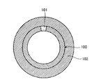
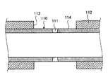
- FIG. 3 is a cross-sectional view showing a high-temperature pipe.
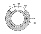
- FIG. 4 is a cross-sectional view of a pipe from which a part of the heat insulating material is removed.
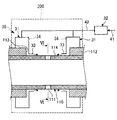
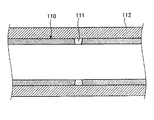
- FIG. 5 is a schematic diagram illustrating a first modification of the cooling device for high-temperature piping according to the first embodiment. 6 is a cross-sectional view taken along the line VI-VI in FIG. 5 showing a cooling device for high-temperature piping.
- FIG. 1 is a schematic diagram illustrating a cooling device for high-temperature piping according to the first embodiment.
- 2 is a cross-sectional view taken along the line II-II of FIG. 1 showing a cooling device for high-temperature piping.
- FIG. 3 is
- FIG. 7 is a cross-sectional view showing a high-temperature pipe.
- FIG. 8 is a cross-sectional view of a pipe from which a part of the heat insulating material is removed.
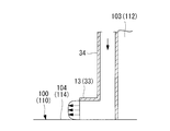
- FIG. 9 is a partial enlarged cross-sectional view illustrating a first modification of the cooling device for high-temperature piping according to the first embodiment.
- FIG. 10 is a front view illustrating a second modification of the cooling device for high-temperature piping according to the first embodiment.
- FIG. 11 is a partially enlarged front view showing a second modification of the cooling device for high-temperature piping according to the first embodiment.
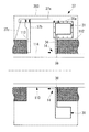
- FIG. 12 is a cross-sectional view in the pipe axis direction showing a second modification of the high-temperature pipe cooling device according to the first embodiment.
- FIG. 13 is a partially enlarged longitudinal sectional view illustrating a second modification of the cooling device for high-temperature piping according to the first embodiment.
- FIG. 14 is a graph showing the relationship between the heat transfer ratio and the guide length.
- FIG. 15 is a front view showing the modification of the board
- FIG. 16 is sectional drawing of the pipe-axis direction showing the modification of the board
- FIG. 17 is a front view showing the modification of the board
- FIG. 18 is a front view illustrating a third modification of the cooling device for high-temperature piping according to the first embodiment.
- FIG. 19 is a perspective view illustrating a third modification of the cooling device for high-temperature piping according to the first embodiment.
- FIG. 20 is a schematic diagram illustrating a cooling device for high-temperature piping according to the second embodiment.
- FIG. 21 is a schematic diagram illustrating a first modification of the cooling device for high-temperature piping according to the second embodiment.
- FIG. 3 is a cross-sectional view showing a high-temperature pipe
- FIG. 4 is a cross-sectional view of the pipe from which a heat insulating material is partially removed.
- the high-temperature pipe is a metallic steam pipe that conveys steam heated by a boiler to a steam turbine, for example, in a thermal power plant, and is heated by high-temperature and high-pressure steam that flows inside.
- High temperature metal piping This metal pipe is periodically subjected to non-destructive inspection, and the degree of creep void growth in the pipe is analyzed to derive the degree of creep damage and the remaining life of the pipe is evaluated. If the risk of creep damage in the period until the next periodic inspection cannot be ignored, the risk of creep damage is reduced by cooling the high-temperature metal piping to lower the temperature.
- the cooling device for a high-temperature pipe cools the surface to be cooled with the exposed surface of the pipe exposed to the outside from the removed portion of the heat insulating material covering the high-temperature pipe. And since metal piping has a higher risk of creep damage in the welded portion than the base metal portion, the periphery of the welded portion is mainly targeted for cooling.
- the high-temperature metal pipe 100 is a steam pipe used in a plant such as a thermal power plant, a nuclear power plant, or a chemical plant.
- the metal pipe 100 is always in a high-temperature and high-pressure environment by flowing a high-temperature and high-pressure fluid (for example, water vapor) inside.
- This metal pipe 100 is an electric resistance welded pipe provided with a welded portion 101 along the axial direction, and the outer surface of the metal pipe 100 is covered with a heat insulating material 102 in order to suppress a decrease in fluid temperature at high temperature and pressure.
- the metal pipe 100 When the metal pipe 100 is used for a long time in a high temperature environment, creep damage progresses and creep voids are generated.
- the creep voids are connected to each other to cause cracks and eventually break. .
- the degree of creep void growth is analyzed by periodic nondestructive inspection to derive the degree of creep damage of each part, and the remaining life of the pipe 100 is evaluated.
- the heat insulating material 102 covering the vicinity of the welded portion 101 where the risk of creep damage cannot be ignored is removed to form the removed portion 103, and the surface to be cooled 104 including the welded portion 101 is exposed. And cooling using the cooling device of the present embodiment.
- FIG. 1 is a schematic view showing a cooling device for high-temperature piping according to the first embodiment
- FIG. 2 is a cross-sectional view taken along the line II-II in FIG. 1 showing the cooling device for high-temperature piping.
- the high-temperature pipe cooling device 10 cools the surface 104 to be cooled in the metal pipe (high-temperature pipe) 100, and includes a cooling medium supply header 11, A cooling medium supply device 12, a cooling medium outflow nozzle 13, and a rain protection hood 200 are provided.
- the hood 200 is indicated by a broken line, and the hood 200 is installed so as to cover the cooling device 10 and the pipe 100.
- Each cooling medium supply header 11 is provided with a cooling medium outflow nozzle 13 facing each other on the opposite side.
- the cooling medium outflow nozzle 13 is extended to the outer peripheral surface side of the pipe 100 along the end face of the heat insulating material 102 formed by the removing section 103 on the side of the removing section 103 in the cooling medium supply header 11, and the leading end thereof is the pipe 100. It is bent along the cooled surface 104 that is the outer peripheral surface of the. Therefore, each cooling medium outflow nozzle 13 is arranged so that the outlets face each other, and the cooling medium flows out along the surface to be cooled 104.
- the cooling medium outflow nozzle 13 is provided along the axial direction of the pipe 100 in the removal portion 103.
- the cooling medium supply device 12 is a fan or a blower, and supplies the cooling medium to each cooling medium supply header 11.
- the intake pipe 21 is connected, and the supply pipe 22 is connected to each cooling medium supply header 11. Therefore, the cooling medium supply device 12 supplies the cooling medium taken in from the intake pipe 21 to each cooling medium supply header 11 through the supply pipe 22.
- the intake pipe 21 is provided with a first temperature sensor 23 for measuring the temperature of the cooling medium flowing inside.
- the 2nd temperature sensor 24 which measures the temperature of the to-be-cooled surface 104 of the piping 100 is provided.
- the temperature sensor is attached to the metal pipe by welding, but at that time, there is a possibility that a different material into the metal pipe, which becomes a cause of generation of voids, may be mixed.
- a non-contact sensor such as a radiation thermometer that does not require welding is desirable as the second temperature sensor 24.
- the control device 25 receives the coolant temperature measured by the first temperature sensor 23 and the temperature of the cooled surface 104 measured by the second temperature sensor 24.
- the control device 25 controls the cooling medium supply amount supplied to the cooling medium supply header 11 by the cooling medium supply device 12 according to the cooling medium temperature measured by the first temperature sensor 23, and the second temperature sensor 24
- the cooling medium supply amount that the cooling medium supply device 12 supplies to the cooling medium supply header 11 is controlled according to the measured temperature of the cooled surface 104.
- the cooling medium supply amount that the cooling medium supply device 12 supplies to the cooling medium supply header 11 is controlled, the cooling medium supply amount that each cooling medium outflow nozzle 13 supplies to the cooled surface 104 is controlled.
- the surrounding environment of the metal pipe 100 to be installed changes periodically with a seasonal cycle for one day.
- the metal temperature of the surface to be cooled 104 and the welded portion 101 of the metal pipe 100 to be cooled due to the temperature change may vary, and the required life extension effect of the pipe 100 may not be obtained.
- the amount of cooling medium supplied to the surface to be cooled 104 is controlled so that the metal temperature of the welded portion 101 of the pipe 100 is kept constant even if the air temperature fluctuates.
- the cooling medium supply device 12 When the cooling medium supply device 12 is operated as described above, the cooling medium is taken in through the intake pipe 21 and supplied to each cooling medium supply header 11 through the supply pipe 22. Each cooling medium supply header 11 flows out the cooling medium from each cooling medium outflow nozzle 13 along the cooled surface 104. As a result, the welded portion 101 is cooled by the cooling medium flowing along the surface to be cooled 104.
- the control device 25 controls the supply amount of the cooling medium supplied from the cooling medium supply device 12 to the cooling medium supply header 11 according to the cooling medium temperature and the temperature of the surface 104 to be cooled.
- the cooling medium supply amount supplied to the surface 104 is controlled. As a result, even if the temperature around the metal pipe 100 changes, the welded portion 101 of the pipe 100 can be controlled to a metal temperature that satisfies the required life.
- FIG. 5 is a schematic diagram showing a first modification of the high-temperature pipe cooling device of the first embodiment, and FIG. FIG. 5 is a cross-sectional view taken along the line VI-VI, FIG. 7 is a cross-sectional view of the high-temperature pipe, and FIG.
- the high-temperature metal pipe 110 is a connection pipe provided with a welded portion 111 along the circumferential direction, and is surrounded by a heat insulating material 112 to suppress a decrease in plant efficiency. Is covered.
- the metal pipe 110 When the metal pipe 110 is used for a long time in a high temperature environment, creep damage is generated and creep voids are generated. The creep voids are connected to each other to cause cracks and eventually break. . In order to prevent this breakage, the degree of creep void growth is analyzed by periodic nondestructive inspection to derive the degree of creep damage of each part, and the remaining life of the pipe 110 is evaluated. Specifically, as shown in FIG. 8, the heat insulating material 112 covering the vicinity of the welded portion 111 having a high risk of creep damage is removed to form a removed portion 113 to expose the cooled surface 114 including the welded portion 111. The cooled surface 114 is cooled by the cooling device of this embodiment.
- the cooling device 30 for high-temperature piping cools the surface 114 to be cooled in the metal piping (high-temperature piping) 110, and includes a cooling medium supply header 31, a cooling medium supply device 32, and the like.
- the cooling medium outlet nozzle 33 and the hood 200 are provided.
- the cooling medium supply header 31 is arranged on both sides along the tube axis direction of the cooled surface 114, that is, the pipe of the piping 110 with respect to the cooled surface 114 so as not to shield heat radiation due to radiation from the cooled surface 114 of the piping 110. It arrange
- the cooling medium supply header 31 is not limited to the case where the cooling medium supply header 31 is disposed outside the heat insulating material 112, and may be disposed outside the surface to be cooled 114, and the heat insulating material 112 is cut out and disposed inside the heat insulating material 112. May be.
- Each cooling medium supply header 31 has the same hollow box shape, and is arranged on the outer peripheral surface of the heat insulating material 112 in a ring shape along the circumferential direction on both sides of the removal portion 113.
- the cooling medium supply header 31 may be configured to be divided into a plurality of parts in the circumferential direction as shown in FIG. In FIG. 10, the cooling medium supply header 31 is divided into three parts, which are divided members 31A, 31B, and 31C.
- the divided members 31A, 31B, and 31C are coupled to each other by, for example, bolts.
- each cooling medium outflow nozzle 33 is provided so as to face each other.
- the cooling medium outflow nozzle 33 is extended to the outer peripheral surface side of the pipe 110 along the end face of the heat insulating material 112 on which the removing section 113 is formed, on the side of the removing section 113 in the cooling medium supply header 31. 110 is bent along a cooled surface 114 which is an outer peripheral surface of 110. Therefore, each cooling medium outflow nozzle 33 is arranged so that the outlets face each other, and the cooling medium flows out along the surface to be cooled 114.
- the cooling medium outflow nozzle 33 is provided along the entire circumferential direction of the pipe 110 in the removal portion 113.
- the cooling medium supply header 31 has a plate member 34 that extends toward the outer peripheral surface of the pipe 110 along the end surface of the heat insulating material 112 on which the removal portion 113 is formed on the removal portion 113 side of the cooling medium supply header 31.
- the plate surface of the plate member 34 is arranged in a direction substantially perpendicular to the pipe axis direction of the pipe 110. As shown in FIG. 10, slits 35 may be formed in the plate member 34 from the vicinity of the surface of the pipe 110 to the outer side.
- the cooling medium supply source side of the cooling medium supply header 31 is substantially at room temperature, a temperature difference close to 500 ° C. occurs in the height direction of the plate member 34. As a result, thermal deformation of several mm occurs at the tip of the cooling medium supply header 31 on the pipe 110 side.
- a sealing material such as a metal foil 36 along the slit 35 as shown in FIG.
- the metal foil 36 is installed on the inner surface side of the cooling medium supply header 31 through which the cooling medium flows. Further, for example, only one side of the slit 35 is fixed to the plate member 34 by spot welding along the slit 35 so that the plate member 34 is not restrained by the metal foil 36. In FIG. 11, the welded portion is indicated by the symbol W.
- the cooling medium supply device 32 shown in FIG. 5 is a fan or a blower, and supplies the cooling medium to each cooling medium supply header 31.
- the intake pipe 41 is connected, and the supply pipe 42 is connected to each cooling medium supply header 31. Therefore, the cooling medium supply device 32 supplies the cooling medium taken in from the intake pipe 41 to each cooling medium supply header 31 through the supply pipe 42.
- the first temperature sensor 23, the second temperature sensor 24, and the control device 25 are provided in the same manner as in the first embodiment, so that the cooling medium temperature and the temperature of the surface 114 to be cooled can be adjusted. Accordingly, the cooling medium supply amount supplied to the cooling medium supply header 31 by the cooling medium supply device 32 may be controlled.
- each cooling medium supply header 31 flows out the cooling medium from each cooling medium outflow nozzle 33 along the cooled surface 114.
- a flow of the cooling medium can be formed along the cooled surface 114, and the welded portion 111 can be effectively cooled.
- the surfaces to be cooled 104 and 114 in the piping 100 and 110 as high-temperature piping are cooled in order to extend the life of the piping 100 and 110.
- cooling that is arranged at a position that does not shield heat radiation due to radiation from the surfaces to be cooled 104 and 114 flows out the cooling medium toward the surfaces to be cooled 104 and 114.
- the cooling medium supply devices 12 and 32 supply the cooling medium to the cooling medium supply headers 11 and 31, the cooling medium is supplied to the cooling medium supply headers 11 and 31, and the cooling medium of the cooling medium supply headers 11 and 31 is changed.
- the cooling medium outflow nozzles 13 and 33 flow out toward the cooled surfaces 104 and 114, and the cooled surfaces 104 and 114 of the pipes 100 and 110 are effectively cooled.
- the cooling medium supply headers 11 and 31 are arranged so as not to shield heat radiation due to radiation from the cooled surfaces 104 and 114, the outside of the cooled surfaces 104 and 114 has an open space with respect to the surroundings. As such, the amount of heat released by radiation is maximized, so that the amount of cooling medium can be suppressed, and the piping 100 and 110 can be effectively cooled to improve the cooling performance.
- the cooling medium supply headers 11 and 31 are arranged outside the heat insulating materials 102 and 112. As a result, the temperature rise when the cooling medium passes through the cooling medium supply headers 11 and 31 can be suppressed, and the surfaces to be cooled 104 and 114 can be effectively cooled.
- the cooling medium supply headers 11 and 31 are supported on the outer surfaces of the heat insulating materials 102 and 112. Therefore, a member for supporting the cooling medium supply headers 11 and 31 is not required separately, and the structure can be simplified.
- the support member 37 includes a first member 37a parallel to the tube axis direction and a second member installed in a direction substantially perpendicular to the tube axis direction. It has the member 37b, the 2nd member 37b, and the wire material 37c connected to the heat insulating material 112.
- the first member 37a is connected to the flange portion 31a of the cooling medium supply header 31 on one end side and is connected to the wire member 37c on the other end side.
- the second member 37b is connected to the pipe 110 on one end side and connected to the first member 37a on the other end side.
- the first member 37a and the second member 37b can prevent the pipe 110 from falling in the tube axis direction
- the wire member 37c can prevent the pipe 110 from falling in the circumferential direction. Since the cooling medium supply header is prevented from falling, the outflow direction of the cooling medium does not change from the surface to be cooled, and the reliability of the cooling device can be improved by maintaining the initial cooling capacity.
- the cooling medium outflow nozzles 13 and 33 flow out the cooling medium along the surfaces to be cooled 104 and 114. Therefore, the entire amount of the cooling medium can be used for cooling the surfaces to be cooled 104 and 114, and the cooling efficiency of the surfaces to be cooled 104 and 114 can be improved.
- the cooling medium supply headers 11 and 31 are arranged on both sides along the cooled surfaces 104 and 114, and the cooling medium outflow nozzles 13 and 33 are provided facing each other. Therefore, the cooling medium is supplied from both sides to the cooled surfaces 104 and 114 to be cooled, and the cooling medium supply amount can be increased to improve the cooling efficiency.
- the cooling medium supply headers 11 and 31 are arranged on both sides along the cooled surfaces 104 and 114.
- the supply headers 11 and 31 may be arranged only on one side.
- the first temperature sensor 23 that measures the temperature of the cooling medium supplied from the cooling medium supply devices 12 and 32 to the cooling medium supply headers 11 and 31 and the first temperature sensor 23 measure the temperature.
- a control device 25 is provided for controlling the cooling medium outflow amount that the cooling medium outflow nozzles 13 and 33 flow out toward the surfaces to be cooled 104 and 114 in accordance with the cooling medium temperature. Therefore, the cooling medium outflow nozzles 13 and 33 control the cooling medium outflow amount flowing out toward the surfaces to be cooled 104 and 114 according to the cooling medium temperature, so that they are required without being influenced by the ambient temperature. A life prolonging effect can be obtained and the reliability of the plant can be improved.
- the second temperature sensor 24 that measures the temperature of the surfaces to be cooled 104 and 114 and the cooling according to the temperature of the surfaces to be cooled 104 and 114 measured by the second temperature sensor 24.
- a control device 25 is provided for controlling the amount of cooling medium flowing out of the medium outflow nozzles 13 and 33 toward the surfaces to be cooled 104 and 114. Therefore, the cooling medium outflow nozzles 13 and 33 control the cooling medium outflow amount that flows out toward the cooled surfaces 104 and 114 according to the temperature of the cooled surfaces 104 and 114, thereby creeping the cooled surfaces 104 and 114. It is possible to take into account the progress of damage and changes in ambient temperature, so that the required life-prolonging effect can be obtained and the reliability of the plant can be improved.
- the present invention is not limited to this example.
- the tip portions of the cooling medium outflow nozzles 13 and 33 are bent along the cooled surfaces 104 and 114 that are outer peripheral surfaces of the pipes 100 and 110. Therefore, as shown in FIG. 9, the velocity distribution and temperature distribution of the cooling medium flowing out from the tip are parabolic, the shearing force in the vicinity of the surfaces to be cooled 104 and 114 is relatively small, and the piping 100 and 110 The heat transfer coefficient between the surface and the cooling medium is low.
- cooling medium outflow nozzles 13 and 33 instead of the cooling medium outflow nozzles 13 and 33, outflow portions are provided in the cooling medium supply headers 11 and 31.
- the cooling medium supply header 31 is provided with an outflow portion 14 as shown in FIGS.
- the outflow part 14 has the board
- An outflow port of the outflow portion 14 is formed by the end portion 34 ⁇ / b> A facing the pipe 110 of the plate member 34 and the surface of the pipe 110.
- the outflow port of the outflow part 14 is provided along the circumferential direction of the piping 110 in the removal part 113, and the cooling medium flows out along the surface 114 to be cooled.
- the velocity distribution and the temperature distribution of the cooling medium flowing out from the outlet of the outflow portion 14 are the maximum near the surface of the surface 114 to be cooled rather than the central portion in the height direction of the outlet as shown in FIG.
- the velocity gradient and the temperature gradient increase near the surface of the pipe 110.
- the shear force near the surface of the pipe 110 is increased and the heat transfer coefficient is increased, so that the surface 114 to be cooled can be effectively cooled.
- the outflow portion 14 may be provided with a curved surface portion 38 having an arcuate cross section inside the outflow port, that is, in the vicinity of the intersection of the end surface of the heat insulating material 112 and the surface of the pipe 110.
- the curved surface portion 38 protrudes from the end surface of the heat insulating material 102 toward the outlet of the outflow portion 14 as it approaches the pipe 110.
- the relationship between the height H of the outlet and the cooling length L which is the distance from the outlet to the welded portion 111 to be cooled, is L / H ⁇ 10-20. If it is this range, since the flow-velocity distribution of a cooling medium is maintained, a high heat transfer rate can be obtained in the welded part 111.
- the difference in heat transfer coefficient between the case where the cooling medium outflow nozzles 13 and 33 are provided and a guide protruding along the pipes 100 and 110 is formed and the case where there is no guide as in the outflow portion 14 is, for example, As shown in FIG. In FIG. 14, the heat transfer coefficient when the guide length of the cooling medium outflow nozzles 13 and 33 is in the range of about 25 mm to 75 mm is compared with the heat transfer coefficient when the outflow portion 14 without a guide is provided. . As shown in FIG. 14, in the cooling medium outflow nozzles 13 and 33 formed with guides, the heat transfer coefficient is reduced to about 70% as compared with the outflow portion 14 without guides, and the outflow portion 14 without guides is better. It can be seen that the heat transfer rate is improved.
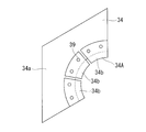
- the plate member 34 provided in the cooling medium supply header 31 is divided into a plurality along the circumferential direction, and a plurality of pieces along the radial direction of the pipe 110 as shown in FIGS. 15 and 16. It may be divided into The plate member 34 is divided along the radial direction by a dividing member 34a on the cooling medium supply source side and a dividing member 34b on the piping 110 side.
- the split members 34a and 34b are coupled to each other by, for example, a bolt 39 and a nut 40.
- the cooling medium supply header can be obtained by simply expanding and contracting the plate member 34 having the divided structure without replacing all the plate members 34. 31 can be installed.
- the dividing member 34 b has, for example, a fan shape, and has a long circumferential direction on the refrigerant supply source side and a short circumferential direction on the piping side.
- the dividing member 34a on the cooling medium supply source side and the dividing member 34b on the piping 110 side are bolt-fastened so that a long hole in the radial direction of the piping 110 is formed in one of the dividing member 34a and the dividing member 34b, and the other A circular hole may be formed in the surface.
- the installation position of the division member 34b ie, the expansion-contraction length of the board
- FIG. 17 shows a case where the opening 44 is formed in the dividing member 34b.
- the spacer 43 is formed so that the position of the bolt hole 45 is different along the radial direction of the pipe 110 for each type.
- the spacer 43 fitted into the opening 44 is selected so that the bolt hole 45 is at an appropriate position in the radial direction of the pipe 110.
- the plate member 34 has a low temperature on the cooling medium supply source side, whereas the pipe 110 thermally expands due to the flow of a high-temperature fluid therein. Therefore, the curvature radius of the pipe 110 is larger than that of the end portion 34A of the plate member 34. growing. Therefore, the plate member 34 may be manufactured in advance in consideration of the thermal expansion of the pipe 110 so that the curvature radius of the end portion 34A of the plate member 34 is larger than the curvature radius of the pipe 110 at a low temperature. Thereby, when the temperature of the piping 110 rises and thermally expands and the radius of curvature of the piping 110 increases, the gap formed between the end portion 34A of the plate member 34 and the piping 110 can be reduced.
- the divided member 34b of the plate member 34 having a divided structure may have a configuration that is always urged toward the pipe 110 in the radial direction of the pipe 110. Thereby, even when the piping 110 is thermally expanded and the radius of curvature increases due to the flow of the high-temperature fluid inside the piping 110, the end portion 34A of the plate member 34 can move following the outer peripheral surface of the piping 110. .
- a spacer 46 is provided between the end 34 ⁇ / b> A of the plate member 34 and the outer peripheral surface of the pipe 110 so that the opening area of the outlet of the cooling medium outlet nozzle 33 is maintained.
- the spacers 46 are installed at a plurality of locations at intervals along the circumferential direction.
- a spring member that presses the divided member 34b against the pipe 110 side, and a ring-shaped expansion and contraction that tightens the outer end 34b1 (see FIG. 16) of the divided member 34b.
- a band member having the property.
- the split member 34b may be biased toward the pipe 110 by providing a magnet in the spacer 46 installed at the end 34A of the split member 34b shown in FIG.
- the cooling medium supply header 31 and the plate material 34 have a ring shape, and are integrally formed in the circumferential direction of the pipe 110. Or what was divided
- the present invention is not limited to this example.
- the cooling medium supply header 31 includes a plurality of header units 47 and a plurality of bellows ducts 48 connecting the header units 47. It may be configured.
- the bellows duct 48 is an example of a telescopic part.
- the header units 47 and the bellows ducts 48 are alternately connected.
- the plurality of header units 47 and the plurality of bellows ducts 48 can be connected in a linear direction.
- the number of combinations of the plurality of header units 47 and the plurality of bellows ducts 48 is determined according to the outer peripheral length of the pipe 110, and the lengths are adjusted.
- the connected header unit 47 and the bellows duct 48 are wound along the outer periphery of the pipe 110, and then one end and the other end are connected to form a ring shape.
- the number of header units 47 and bellows ducts 48 may be prepared in advance according to the pipe 110 having the maximum diameter assumed in advance.
- each header unit 47 has a header portion 49 and an outflow portion 14.
- the outflow portion 14 side in contact with the pipe 110 is formed of a heat-resistant member such as stainless steel, and the header portion 49 side close to room temperature is formed of a lightweight member such as an aluminum alloy. Thereby, the weight reduction of the cooling-medium supply header 31 whole can be achieved. Since the header portion 49 and the outflow portion 14 side are made of different materials, they are connected, for example, by caulking or rivets.
- each header unit 47 has, for example, a structure in which each header unit 47 is closed by a side end face 14a, and the header portion 49 side is connected by a bellows duct 48.
- the outflow part 14 of each header unit 47 may also be connected by a bellows duct, and may have a structure through which a cooling medium can flow. Since the bellows duct 48 connected on the header portion 49 side is disposed under conditions close to room temperature, the bellows duct 48 may be made of sheet-like heat-resistant synthetic resin instead of metal.
- the cooling medium supply header 31 and the plate member 34 are configured by the plurality of header units 47 and the plurality of bellows ducts 48 connecting the header units 47.
- the supply header 31 can be easily attached to the pipe 110 without changing the structure.
- the cooling medium supply header 31 arranged in a ring shape along the circumferential direction of the pipe 110 but also the cooling medium supply header 11 arranged along the pipe axis direction of the pipe 110 if arranged in a straight line. It is also applicable to.
- the bellows duct 48 does not necessarily have a bellows structure and the header units 47 are connected by the member which can adjust the space
- a sheet member made of cloth, metal or rubber may be provided instead of the bellows duct 48.
- FIG. 20 is a schematic diagram illustrating a cooling device for high-temperature piping according to the second embodiment
- FIG. 21 is a schematic diagram illustrating a first modification of the cooling device for high-temperature piping according to the second embodiment.
- symbol is attached
- the cooling device 50 for high-temperature piping cools the surface to be cooled 104 in the metal piping 100, and includes a cooling medium supply header 51, a cooling medium supply device 52, A cooling medium outlet nozzle 53 and a hood 200 are provided.
- the cooling medium supply header 51 is disposed so as not to shield heat radiation due to radiation from the cooled surface 104 of the metal pipe 100.
- Each cooling medium supply header 51 is supported so as to be placed on the outer peripheral surface of the heat insulating material 102 on both sides in the circumferential direction of the removal portion 103 of the heat insulating material 102.
- Each cooling medium supply header 51 is provided on both sides in the circumferential direction of the removal portion 103 of the heat insulating material 102 so that the cooling medium outflow nozzles 53 face each other.
- the cooling medium outflow nozzle 53 is extended to the outer peripheral surface side of the pipe 100 along the end surface of the heat insulating material 102 where the removing portion 103 is formed on the side of the removing portion 103 in the cooling medium supply header 51, and the tip portion is welded. It is inclined with respect to the outer peripheral surface of the pipe 100 so as to face the portion 101. Therefore, each cooling medium outflow nozzle 53 is arranged so that the outlets face each other, and the cooling medium flows out toward the welded portion 101 on the surface to be cooled 104.
- the cooling medium supply device 52 is a fan or a blower, and supplies the cooling medium to each cooling medium supply header 51.
- the cooling medium supply device 52 is connected to the intake pipe 61 and is connected to the supply pipe 62 up to each cooling medium supply header 51. Therefore, the cooling medium supply device 52 can supply the cooling medium taken in from the intake pipe 61 to each cooling medium supply header 51 through the supply pipe 62.
- each cooling medium supply header 51 flows out the cooling medium from each cooling medium outflow nozzle 53 toward the welded portion 101 of the surface to be cooled 104.
- the welded portion 101 is cooled with a high heat transfer coefficient by the coolant that has flowed out, so that the cooling efficiency can be improved.
- the cooling device 70 cools the surface 114 to be cooled in the metal pipe 110, and includes a cooling medium supply header 71, a cooling medium supply device 72, and a cooling medium outflow nozzle. 73 and a hood 200.
- the cooling medium supply header 71 is disposed so as not to shield heat radiation due to radiation from the cooled surface 114 of the pipe 110. Each cooling medium supply header 71 is supported so as to be placed on the outer peripheral surface of the heat insulating material 112.
- Each cooling medium supply header 71 is provided so that the cooling medium outflow nozzles 73 face each other on the opposite side.
- the cooling medium outflow nozzle 73 is extended to the outer peripheral surface side of the pipe 110 along the end surface of the heat insulating material 112 on which the removing portion 113 is formed on the side of the removing portion 113 in the cooling medium supply header 71, and the tip portion is welded. It is inclined with respect to the outer peripheral surface of the pipe 110 so as to face the portion 111. Therefore, each cooling medium outflow nozzle 73 is arrange
- the cooling medium supply device 72 is a fan or a blower, and supplies the cooling medium to each cooling medium supply header 71.
- the cooling medium supply device 72 is connected to an intake pipe 81 and is connected to a supply pipe 82 up to each cooling medium supply header 71. Therefore, the cooling medium supply device 72 can supply the cooling medium taken in from the intake pipe 81 to each cooling medium supply header 71 through the supply pipe 82.
- each cooling medium supply header 71 flows out of the cooling medium from each cooling medium outflow nozzle 73 toward the welded portion 111 of the surface 114 to be cooled, and the welded portion 111 is cooled with a high heat transfer rate by the discharged cooling medium. .
- Cooling medium supply headers 51, 71 arranged so as not to shield heat radiation due to radiation, cooling medium supply devices 52, 72 for supplying a cooling medium to the cooling medium supply headers 51, 71, and cooling medium supply headers 51, 71 Cooling medium outflow nozzles 53 and 73 for flowing out the cooling medium toward the surfaces to be cooled 104 and 114 are provided.
- the cooling medium supply headers 51 and 71 are arranged on both sides along the surfaces to be cooled 104 and 114.
- the cooling medium supply is provided.
- the headers 51 and 71 may be arranged only on one side.
- the cooling medium supply devices 52 and 72 supply the cooling medium to the cooling medium supply headers 51 and 71
- the cooling medium is supplied to the cooling medium supply headers 51 and 71
- the cooling medium of the cooling medium supply headers 51 and 71 is supplied.
- the cooling medium outflow nozzles 53 and 73 flow out toward the surfaces to be cooled 104 and 114 to cool the surfaces to be cooled 104 and 114 of the pipes 100 and 110 with a high heat transfer coefficient.
- the cooling medium supply headers 51 and 71 are arranged so as not to shield heat radiation due to radiation from the cooled surfaces 104 and 114, the outside of the cooled surfaces 104 and 114 has an open space. Since the amount of heat released by radiation is maximized as described above, the amount of the cooling medium can be suppressed and the pipes 100 and 110 can be effectively cooled.
- the cooling medium outflow nozzles 53 and 73 flow out the cooling medium toward the welds 101 and 111. Therefore, since the cooling medium cools the welds 101 and 111 having a high risk of creep damage with a high heat transfer coefficient, the surfaces to be cooled 104 and 114 can be efficiently cooled.
- the cooling medium outflow nozzles 13 and 33 flow out the cooling medium along the cooled surfaces 104 and 114, or the cooling medium outflow nozzles 53 and 73 direct the cooling medium toward the welded portions 101 and 111.
- the present invention is not limited to this configuration.
- the cooling medium outflow nozzle may flow out the cooling medium toward the surfaces to be cooled 104 and 114 and supply the cooling medium along the welds 101 and 111.
- the cooling medium amount to the cooling medium supply header is controlled according to the ambient temperature and the surface temperature to be cooled.
- the cooling medium supply is performed in consideration of the weather such as wind speed and rain.
- the amount of the cooling medium to the header may be controlled.
- the cooling medium is air, but an inert gas such as nitrogen gas may be used.
- Cooling device 11 Cooling medium supply header 12: Cooling medium supply device 13: Cooling medium outflow nozzle 14: Outflow part 14a: Side end surface 21: Intake pipe 22: Supply pipe 23: 1st temperature sensor 24: 2nd temperature Sensor 25: Control device 30: Cooling device 31: Cooling medium supply header 31A: Dividing member 31B: Dividing member 31C: Dividing member 31a: Flange portion 32: Cooling medium supply device 33: Cooling medium outflow nozzle 34: Plate material 34A: End portion 34a: Dividing member 34b: Dividing member 34b1: Outer end 35: Slit 36: Metal foil 37: Support member 37a: First member 37b: Second member 37c: Wire member 38: Curved portion 39: Bolt 40: Nut 41 : Intake pipe 42: Supply pipe 43: Spacer 44: Opening 45: Bolt hole 46: Space 47: header unit 48: bellows duct 49: header section 50: cooling device 51: cooling medium supply header 52: cooling
Landscapes
- Engineering & Computer Science (AREA)
- General Engineering & Computer Science (AREA)
- Mechanical Engineering (AREA)
- Chemical & Material Sciences (AREA)
- Combustion & Propulsion (AREA)
- Monitoring And Testing Of Nuclear Reactors (AREA)
- Heat Treatment Of Articles (AREA)
Abstract
高温配管の冷却装置において、高温配管を効率良く冷却して冷却性能の向上を図る。高温配管としての配管(100)における被冷却面(104)を冷却する高温配管の冷却装置(10)において、被冷却面(104)から周囲への放射による放熱を遮蔽しないように配置されて冷却媒体を被冷却面(104)に向けて流出する冷却媒体供給ヘッダ(11)と、冷却媒体供給ヘッダ(11)に冷却媒体を供給する冷却媒体供給装置(12)とを備える。
Description
本発明は、火力発電プラント、原子力発電プラント、化学プラントなどのプラントで用いられる高温配管の冷却装置に関するものである。
例えば、火力発電プラントでは、ボイラで加熱された水蒸気を蒸気タービンに搬送する配管が多数配置されている。この配管は、金属配管であり、内部に高温で高圧の水蒸気が流動することから、この水蒸気により加熱された高温状態の環境下にある。このような金属配管は、上述した環境下で長時間使用されると、クリープ損傷が進行してクリープボイドが発生し、このクリープボイドがつながることで亀裂が生じ、最終的には破断に至る可能性が高い。
このような配管の破断を防止するため、定期的な非破壊検査によりクリープボイドの成長度合いを分析してクリープ損傷度を導出し、金属配管の余寿命評価を行っている。この場合、一般的に、金属配管は、母材部に比べて溶接部のクリープ損傷リスクが高いことから、主に、この溶接部が検査対象箇所となる。非破壊検査の結果、次の定期検査までの期間におけるクリープ損傷リスクを無視できない場合、プラント全体の運転温度を下げることで、金属配管のメタル温度を下げ、クリープ損傷リスクを低減する対策を講じるが、プラント全体の運転温度を下げると、プラントの運転効率が低下してしまう欠点がある。
このように次の定期検査までの期間におけるクリープ損傷リスクを無視できない場合、金属配管を冷却してメタル温度を低下することで、クリープ損傷リスクを低減する手法が考えられる。このような技術として例えば、下記特許文献1に記載されたものがある。
上述した特許文献1では、高温金属配管の外周部を被覆する断熱材を撤去し、露出した高温金属配管の外周部に放熱フィン、冷却配管、供給配管などの冷却装置を配置して高温金属配管を冷却する。しかし、露出した高温金属配管の外周部に放熱フィン、冷却配管、供給配管などの冷却装置を配置すると、高温金属配管から周囲低温部への放射による放熱を遮蔽することになり、冷却効率が低下する。
本発明は上述した課題を解決するものであり、高温金属配管の冷却性能の向上を図る冷却装置を提供することを目的とする。
上述の目的を達成するための本発明の高温配管の冷却装置は、高温配管を延命化するために被冷却面の周囲に設置される高温配管の冷却装置において、前記被冷却面から周囲への放射による放熱を遮蔽しない位置に配置されて冷却媒体を前記被冷却面に向けて流出する冷却媒体供給ヘッダと、前記冷却媒体供給ヘッダに冷却媒体を供給する冷却媒体供給装置と、を備えることを特徴とする。
従って、冷却媒体供給装置が冷却媒体供給ヘッダに冷却媒体を供給すると、この冷却媒体供給ヘッダに冷却媒体が供給され、冷却媒体供給ヘッダの冷却媒体が被冷却面に向けて流出され、高温配管が冷却される。このとき、冷却媒体供給ヘッダが被冷却面に対向する領域を除く被冷却面の周辺部に配置されるため、被冷却面に対向する領域が開放領域となる。そのため、高温配管は、遮蔽されることなく被冷却面から放射により放熱されることとなり、高温配管を効率良く冷却することができる。
本発明の高温配管の冷却装置では、前記被冷却面は、前記高温配管を被覆する断熱材の撤去部から露出した前記高温配管の露出表面であり、前記冷却媒体供給ヘッダは、前記被冷却面の外側に配置されることを特徴としている。
従って、被冷却面が高温配管を被覆する断熱材の撤去部から露出した露出表面であり、冷却媒体供給ヘッダが被冷却面の外側に配置されることで、被冷却面に対して冷却媒体供給ヘッダが放射による放熱を遮蔽することなく、被冷却面を効果的に冷却できる。また冷却媒体供給ヘッダと高温配管の間には断熱材があり、冷却媒体供給ヘッダの温度上昇を抑制できる。そのため、冷却媒体供給ヘッダ内を冷却媒体が通過する際の温度上昇を抑制でき、被冷却面を効果的に冷却できる。
本発明の高温配管の冷却装置では、前記冷却媒体供給ヘッダは、前記断熱材の外面に支持されることを特徴とする。
従って、冷却媒体供給ヘッダを断熱材の外面に支持することで、別途、冷却媒体供給ヘッダを支持するための部材が不要となり、構造を簡略化できる。
本発明の高温配管の冷却装置では、前記冷却媒体供給ヘッダを、サポート部材によって、前記高温配管及び前記断熱材の外面に支持することを特徴とする。
従って、冷却媒体供給ヘッダが、高温配管に対して管軸方向又は周方向に倒れることを抑制するため、冷却媒体の流出方向が被冷却面から変わることがなく、初期の冷却能力を維持することで冷却装置の信頼性を向上できる。
本発明の高温配管の冷却装置では、前記冷却媒体供給ヘッダの冷却媒体を前記被冷却面に向けて流出する冷却媒体流出ノズルが設けられることを特徴としている。
従って、冷却媒体供給ヘッダの冷却媒体は、冷却媒体流出ノズルから被冷却面に向けて流出され、高温配管が冷却される。そのため、高温配管は、遮蔽されることなく被冷却面から放射により放熱されることとなり、高温配管を効率良く冷却することができる。
本発明の高温配管の冷却装置では、前記冷却媒体流出ノズルは、冷却媒体を前記被冷却面に沿って流出することを特徴とする。
従って、冷却媒体流出ノズルによって冷却媒体を被冷却面に沿って流出することで、冷却媒体が被冷却面に沿って流れるため、冷却媒体を被冷却面に効率的に供給して冷却効率を向上できる。
本発明の高温配管の冷却装置では、前記被冷却面は、溶接部を含み、前記冷却媒体流出ノズルは、冷却媒体を前記溶接部に向けて流出することを特徴とする。
従って、冷却媒体流出ノズルによって冷却媒体を溶接部に向けて流出することで、冷却媒体がクリープ損傷リスクが無視できない溶接部へ直接供給され、被冷却面を効率的に冷却できる。
本発明の高温配管の冷却装置において、前記冷却媒体供給ヘッダは、前記冷却媒体供給ヘッダの冷却媒体を前記被冷却面に向けて流出する冷却媒体流出口が設けられ、前記高温配管を被覆する断熱材の撤去部に沿って設けられた板材を有し、前記板材の前記高温配管側の端部と前記高温配管の表面によって前記冷却媒体流出口が形成されることを特徴とする。
従って、冷却媒体流出口から流出される冷却媒体の速度分布及び温度分布は、冷却媒体流出口の高さ方向中央部分よりも被冷却面の表面近傍側で最大となり、速度勾配及び温度勾配が高温配管の表面近傍で大きくなる。その結果、冷却媒体流出ノズルが設けられる場合に比べて、高温配管の表面近傍のせん断力が大きくなり、熱伝達率が向上するため、効果的に冷却できる。
本発明の高温配管の冷却装置において、前記冷却媒体供給ヘッダは、前記高温配管を被覆する断熱材の撤去部に沿って設けられた板材を有し、前記板材は、前記高温配管側から外側へ向けてスリットが形成されていることを特徴とする。
従って、板材に設けられたスリットは熱変形代として機能するので、熱変形により生じる冷却媒体流出口の変形を抑制する。この結果、冷却能力の低下を抑制し、前記冷却装置の信頼性を向上することができる。
本発明の高温配管の冷却装置において、前記冷却媒体供給ヘッダは、前記高温配管を被覆する断熱材の撤去部に沿って設けられた板材を有し、前記板材は、前記高温配管に沿って複数に分割された分割部材を組み合わせて構成されることを特徴とする。
従って、高温配管が設置される現地において、冷却媒体供給ヘッダの分割部材を組み合わせるだけで、リング形状をなす冷却媒体供給ヘッダを容易に組み立てることが可能であり、据付コストを削減することができる。
本発明の高温配管の冷却装置において、前記冷却媒体供給ヘッダは、前記高温配管を被覆する断熱材の撤去部に沿って設けられた板材を有し、前記板材は、前記高温配管に沿って複数に分割された分割部材を組み合わせて構成され、前記板材における前記高温配管側の端部の位置が調整可能であることを特徴とする。
従って、高温配管の配管径が異なる場合でも、分割部材同士の結合位置を変更することにより、板材をすべて取り換えることなく、分割構造を有する板材を伸縮させるだけで、冷却媒体供給ヘッダを容易に設置することが可能であり、据付コストを削減することができる。
本発明の高温配管の冷却装置では、前記冷却媒体供給ヘッダは、前記冷却媒体が流通しつつ、前記冷却媒体を前記被冷却面に向けて流出する複数のヘッダユニットと、二つの前記ヘッダユニット間に設けられる伸縮部とを有し、前記ヘッダユニットと前記伸縮部が交互に連結されていることを特徴とする。
従って、複数のヘッダユニットと複数の伸縮部は、高温配管に沿った長さに合わせて組合せ数が決定され、自在に長さを調整できるので、高温配管を早急に冷却する事態が生じた場合、冷却媒体供給ヘッダを迅速に設置することができる。
本発明の高温配管の冷却装置では、前記冷却媒体供給装置が前記冷却媒体供給ヘッダに供給する冷却媒体の温度を計測する温度センサと、前記温度センサが計測した冷却媒体の温度に応じて前記冷却媒体流出ノズル又は前記冷却媒体流出口が前記被冷却面に向けて流出する冷却媒体の流出量を制御する制御装置とが設けられることを特徴とする。
従って、冷却媒体供給ヘッダに供給する冷却媒体の温度に応じて冷却媒体流出ノズル又は冷却媒体流出口が被冷却面に向けて流出する冷却媒体の流出量を制御することで、周囲の環境温度が変化しても、被冷却面を常に要求寿命を満足するために必要な温度に冷却し、これを維持できる。
本発明の高温配管の冷却装置では、前記被冷却面の温度を計測する温度センサと、前記温度センサが計測した前記被冷却面の温度に応じて前記冷却媒体流出ノズル又は前記冷却媒体流出口が前記被冷却面に向けて流出する冷却媒体の流出量を制御する制御装置とが設けられることを特徴としている。
従って、被冷却面の温度に応じて冷却媒体流出ノズル又は冷却媒体流出口が被冷却面に向けて流出する冷却媒体の流出量を制御することで、被冷却面のクリープ損傷度合いや周囲の環境温度が変化しても、被冷却面を常に要求寿命を満足するために必要な温度に冷却し、これを維持できる。
本発明の高温配管の冷却装置によれば、冷却媒体流出ノズルを有する冷却媒体供給ヘッダを被冷却面の周辺部に配置するので、被冷却面から周囲への放射による放熱を遮蔽するものが配置されず、被冷却面から効果的に放熱することで、高温配管の冷却性能を向上できる。また冷却媒体供給ヘッダの高温配管の間に断熱材があり、冷却媒体供給ヘッダの温度上昇を抑制できるため、冷却媒体供給ヘッダ内を冷却媒体が通過する際の温度上昇を抑制でき、被冷却面を効果的に冷却できる。
以下に添付図面を参照して、本発明に係る高温配管の冷却装置の好適な実施形態を詳細に説明する。なお、この実施形態により本発明が限定されるものではなく、また、実施形態が複数ある場合には、各実施形態を組み合わせて構成するものを含む。
[第1実施形態]
図3は、高温配管を表す断面図、図4は、断熱材を一部除去した配管の断面図である。
図3は、高温配管を表す断面図、図4は、断熱材を一部除去した配管の断面図である。
第1実施形態において、高温配管は、例えば、火力発電プラントにて、ボイラで加熱された水蒸気を蒸気タービンに搬送する金属性の水蒸気配管であって、内部に流動する高温高圧の水蒸気により加熱された高温金属配管である。この金属配管には、定期的に非破壊検査が実施され、配管のクリープボイドの成長度合いを分析してクリープ損傷度を導出し、配管の余寿命評価を行う。次の定期検査までの期間におけるクリープ損傷リスクを無視できない場合、高温金属配管を冷却して温度を下げることで、クリープ損傷リスクを低減する。
本実施形態の高温配管の冷却装置は、高温配管を被覆する断熱材の撤去部から外部に露出した配管の露出表面を被冷却面とし、この被冷却面を冷却するものである。そして、金属配管は、母材部に比べて溶接部のクリープ損傷リスクが高いことから、主に、この溶接部周辺を冷却対象とする。
まず、高温配管の配置状態について説明する。図3に示すように、高温金属配管100は、例えば、火力発電プラントや原子力発電プラントや化学プラントなどのプラントで用いられる水蒸気配管である。この金属配管100は、内部に高温高圧の流体(例えば、水蒸気)を流動することで、常時、高温高圧環境下にある。この金属配管100は、軸方向に沿って溶接部101が設けられる電縫管であって、高温高圧の流体温度低下を抑制するために断熱材102で金属配管100の外面が覆われる。
金属配管100は、高温環境下で長時間使用されると、クリープ損傷が進行してクリープボイドが発生し、このクリープボイドがつながることで亀裂が生じ、最終的には破断に至る可能性がある。この破断を防止するため、定期的な非破壊検査によりクリープボイドの成長度合いを分析して各部のクリープ損傷度を導出し、配管100の余寿命評価を行う。具体的には、図4に示すように、クリープ損傷リスクを無視できない溶接部101の近傍を覆う断熱材102を除去して撤去部103を形成し、溶接部101を含む被冷却面104を露出させ、本実施形態の冷却装置を用いて冷却する。
図1は、第1実施形態の高温配管の冷却装置を表す概略図、図2は、高温配管の冷却装置を表す図1のII-II断面図である。
第1実施形態において、図1及び図2に示すように、高温配管の冷却装置10は、金属配管(高温配管)100における被冷却面104を冷却するものであり、冷却媒体供給ヘッダ11と、冷却媒体供給装置12と、冷却媒体流出ノズル13、雨除けのフード200とを備える。なお、図1では、フード200を破線で示しており、フード200は、冷却装置10及び配管100を覆うように設置される。
冷却媒体供給ヘッダ11は、配管100の被冷却面104からの放射による放熱を遮蔽しないように、被冷却面104に沿う両側、つまり、被冷却面104に対して配管100の周方向にずれた両側の断熱材102の外側に配置される。なお、冷却媒体供給ヘッダ11は、断熱材102の外側に配置される場合に限定されず、被冷却面104の外側に配置されればよく、例えば断熱材102を切り欠いて断熱材102内に配置されてもよい。
各冷却媒体供給ヘッダ11は、対向する側に冷却媒体流出ノズル13をそれぞれ対向するように備える。冷却媒体流出ノズル13は、冷却媒体供給ヘッダ11における撤去部103側で、この撤去部103が形成する断熱材102の端面に沿って配管100の外周面側に延出され、先端部が配管100の外周面である被冷却面104に沿って屈曲している。そのため、各冷却媒体流出ノズル13は、流出口が対向するように配置され、冷却媒体を被冷却面104に沿って流出する。なお、冷却媒体流出ノズル13は、撤去部103における配管100の軸方向に沿って設けられる。
冷却媒体供給装置12は、ファンやブロアであって、各冷却媒体供給ヘッダ11に冷却媒体を供給する。冷却媒体供給装置12は、取込配管21が連結されると共に、各冷却媒体供給ヘッダ11まで供給配管22が連結されている。そのため、冷却媒体供給装置12は、取込配管21から取り込んだ冷却媒体を供給配管22により各冷却媒体供給ヘッダ11に供給する。
取込配管21は、内部を流れる冷却媒体温度を計測する第1温度センサ23が設けられる。また、配管100の被冷却面104の温度を計測する第2温度センサ24が設けられる。金属配管を熱電対など直接計測する温度センサで計測する場合、温度センサを金属配管に溶接で取り付けるが、その際にボイドの発生要因となる、金属配管への異材が混入する可能性がある。これを抑制するため第2温度センサ24として、溶接を必要としない放射温度計のような非接触センサが望ましい。制御装置25は、第1温度センサ23が計測した冷却媒体温度が入力されると共に、第2温度センサ24が計測した被冷却面104の温度が入力される。そして、制御装置25は、第1温度センサ23が計測した冷却媒体温度に応じて冷却媒体供給装置12が冷却媒体供給ヘッダ11に供給する冷却媒体供給量を制御すると共に、第2温度センサ24が計測した被冷却面104の温度に応じて冷却媒体供給装置12が冷却媒体供給ヘッダ11に供給する冷却媒体供給量を制御する。冷却媒体供給装置12が冷却媒体供給ヘッダ11に供給する冷却媒体供給量を制御すると、各冷却媒体流出ノズル13が被冷却面104に供給する冷却媒体供給量が制御される。
即ち、設置される金属配管100の周囲環境は、一日は季節のサイクルで周期的に変化する。この気温変化により冷却される金属配管100の被冷却面104や溶接部101のメタル温度が変動し、要求される配管100の延命効果が得られない可能性がある。この対策として、気温が変動しても配管100の溶接部101のメタル温度が一定に維持されるように、被冷却面104に供給する冷却媒体供給量を制御する。
以上のように冷却媒体供給装置12を作動すると、取込配管21を通して冷却媒体を取り込み、供給配管22を通して各冷却媒体供給ヘッダ11に冷却媒体を供給する。各冷却媒体供給ヘッダ11は、各冷却媒体流出ノズル13から被冷却面104に沿って冷却媒体を流出する。この結果、被冷却面104に沿って流れる冷却媒体により、溶接部101が冷却される。このとき、制御装置25は、冷却媒体温度と被冷却面104温度に応じて冷却媒体供給装置12が冷却媒体供給ヘッダ11に供給する冷却媒体供給量を制御し、冷却媒体流出ノズル13から被冷却面104に供給される冷却媒体供給量を制御する。
以上の結果、金属配管100周囲の気温が変化しても、配管100の溶接部101を、要求される寿命を満足するメタル温度に制御できる。
以上の結果、金属配管100周囲の気温が変化しても、配管100の溶接部101を、要求される寿命を満足するメタル温度に制御できる。
なお、上述の実施形態では、金属配管100の軸方向に沿って溶接部101を有する電縫管として説明したが、この構成に限定されるものではない。即ち、金属配管100の周方向に溶接部101がある場合について、図5に第1実施形態の高温配管の冷却装置の第1変形例を表す概略図、図6に高温配管の冷却装置を表す図5のVI-VI断面図、図7に高温配管の断面図、図8に断熱材を一部除去した配管の断面図、を示す。
第1変形例において、図7に示すように、高温金属配管110は、周方向に沿って溶接部111が設けられる接続配管であって、プラント効率の低下を抑制するために断熱材112で周囲が覆われる。
金属配管110は、高温環境下で長時間使用されると、クリープ損傷が進行してクリープボイドが発生し、このクリープボイドがつながることで亀裂が生じ、最終的には破断に至る可能性がある。この破断を防止するため、定期的な非破壊検査によりクリープボイドの成長度合いを分析して各部のクリープ損傷度を導出し、配管110の余寿命評価を行っている。具体的には、図8に示すように、クリープ損傷リスクが高い溶接部111の近傍を覆う断熱材112を除去して撤去部113を形成し、溶接部111を含む被冷却面114を露出させ、被冷却面114を本実施形態の冷却装置により冷却する。
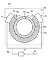
図5及び図6に示すように、高温配管の冷却装置30は、金属配管(高温配管)110における被冷却面114を冷却するものであり、冷却媒体供給ヘッダ31と、冷却媒体供給装置32と、冷却媒体流出ノズル33、フード200とを備える。
冷却媒体供給ヘッダ31は、配管110の被冷却面114からの放射による放熱を遮蔽しないように、被冷却面114の管軸方向に沿う両側、つまり、被冷却面114に対して配管110の管軸方向にずれた両側の断熱材112の外側に配置される。なお、冷却媒体供給ヘッダ31は、断熱材112の外側に配置される場合に限定されず、被冷却面114の外側に配置されればよく、断熱材112を切り欠いて断熱材112内に配置されてもよい。
各冷却媒体供給ヘッダ31は、同様の中空の箱型形状をなし、断熱材112の外周面に撤去部113の両側で、周方向に沿ったリング形状をなして配置される。
各冷却媒体供給ヘッダ31は、同様の中空の箱型形状をなし、断熱材112の外周面に撤去部113の両側で、周方向に沿ったリング形状をなして配置される。
なお、冷却媒体供給ヘッダ31は、図10に示すように、周方向に複数分割可能な構成としてもよい。図10では、冷却媒体供給ヘッダ31は、3分割されており、分割部材31A,31B,31Cからなる。分割部材31A,31B,31Cは、例えばボルトによって互いに結合される。これにより、配管110が設置されている現地において、冷却媒体供給ヘッダ31の分割部材31A,31B,31Cを組み合わせるだけで、リング形状をなす冷却媒体供給ヘッダ31を容易に設置できるため、据付コストを低減することができる。
図5に示すように、各冷却媒体供給ヘッダ31では、冷却媒体流出ノズル33がそれぞれ対向するように設けられる。冷却媒体流出ノズル33は、冷却媒体供給ヘッダ31における撤去部113側で、この撤去部113が形成される断熱材112の端面に沿って配管110の外周面側に延出され、先端部が配管110の外周面である被冷却面114に沿って屈曲している。そのため、各冷却媒体流出ノズル33は、流出口が対向するように配置され、冷却媒体を被冷却面114に沿って流出する。なお、冷却媒体流出ノズル33は、撤去部113における配管110の周方向の全域に沿って設けられる。
冷却媒体供給ヘッダ31は、冷却媒体供給ヘッダ31における撤去部113側で、この撤去部113が形成される断熱材112の端面に沿って配管110の外周面側に延出される板材34を有する。板材34の板面は、配管110の管軸方向に対して略垂直方向に配置される。図10に示すように、板材34には、配管110の表面近傍から外側方向へ、スリット35が形成されてもよい。
冷却媒体供給ヘッダ31の配管110側の先端は、高温部分に接するため、配管110の外面温度(約500℃~550℃)まで昇温する。しかし、冷却媒体供給ヘッダ31の冷却媒体供給源側は、ほぼ室温であるため、板材34の高さ方向には500℃近い温度差が生じる。この結果、冷却媒体供給ヘッダ31の配管110側の先端では、数mmの熱変形が生じる。この熱変形により、冷却媒体の流出速度が局所的に低下するので、被冷却面114温度が不均一となり、この結果、溶接部111の余寿命が不均一となるので、プラントの信頼性が低下する。
これに対し、板材34にスリット35を設けることで、スリット35が、冷却媒体供給ヘッダ31の配管110側の先端で生じる熱変形代として機能するため、先端の熱変形を抑制し、この結果、冷却媒体の流出速度の不均一化を抑制し、プラントの信頼性を向上できる。なお、スリット35は、所定間隔を空けて、複数本設けられる。
これに対し、板材34にスリット35を設けることで、スリット35が、冷却媒体供給ヘッダ31の配管110側の先端で生じる熱変形代として機能するため、先端の熱変形を抑制し、この結果、冷却媒体の流出速度の不均一化を抑制し、プラントの信頼性を向上できる。なお、スリット35は、所定間隔を空けて、複数本設けられる。
なお、スリット35から冷却媒体が漏れるのを防止するため、図11に示すように、金属箔36などのシール材をスリット35に沿って設けることが望ましい。金属箔36は、冷却媒体が流通する冷却媒体供給ヘッダ31の内面側に設置される。また、金属箔36によって板材34が拘束されないように、例えば、スリット35に沿ってスリット35の片側のみをスポット溶接によって板材34に固定する。図11では、溶接部分を符号Wで示している。冷却媒体供給ヘッダ31に冷却媒体が供給されると、内圧が上昇するため、金属箔36と板材34が密着して、冷却媒体の漏出が抑制される。
図5に示す冷却媒体供給装置32は、ファンもしくはブロアであって、各冷却媒体供給ヘッダ31に冷却媒体を供給する。冷却媒体供給装置32は、取込配管41が連結されると共に、各冷却媒体供給ヘッダ31まで供給配管42が連結される。そのため、冷却媒体供給装置32は、取込配管41から取り込んだ冷却媒体を供給配管42により各冷却媒体供給ヘッダ31に供給する。
なお、図示しないが、この第1変形例でも、第1実施形態と同様に、第1温度センサ23、第2温度センサ24、制御装置25を設け、冷却媒体温度や被冷却面114の温度に応じて冷却媒体供給装置32が冷却媒体供給ヘッダ31に供給する冷却媒体供給量を制御しても良い。
そのため、冷却媒体供給装置32を作動すると、取込配管41を通して冷却媒体を取り込み、供給配管42を通して各冷却媒体供給ヘッダ31に供給する。各冷却媒体供給ヘッダ31は、各冷却媒体流出ノズル33から被冷却面114に沿って冷却媒体を流出する。
この結果、被冷却面114に沿って冷却媒体の流れを形成し、溶接部111を効果的に冷却することができる。
この結果、被冷却面114に沿って冷却媒体の流れを形成し、溶接部111を効果的に冷却することができる。
このように第1実施形態の高温配管の冷却装置にあっては、配管100,110を延命化するために高温配管としての配管100,110における被冷却面104,114を冷却するように被冷却面104,114の周囲に設置される配管の冷却装置において、被冷却面104,114からの放射による放熱を遮蔽しない位置に配置されて冷却媒体を被冷却面104,114に向けて流出する冷却媒体供給ヘッダ11,31と、冷却媒体供給ヘッダ11,31に冷却媒体を供給する冷却媒体供給装置12,32と、冷却媒体供給ヘッダ11,31の冷却媒体を被冷却面104,114に向けて流出する冷却媒体流出ノズル13,33を備える。
従って、冷却媒体供給装置12,32が冷却媒体供給ヘッダ11,31に冷却媒体を供給すると、この冷却媒体供給ヘッダ11,31に冷却媒体が供給され、冷却媒体供給ヘッダ11,31の冷却媒体が冷却媒体流出ノズル13,33から被冷却面104,114に向けて流出され、配管100,110の被冷却面104,114が効果的に冷却される。
このとき、冷却媒体供給ヘッダ11,31が被冷却面104,114からの放射による放熱を遮蔽しないように配置されるため、被冷却面104,114の外側が周囲に対して開放空間を持つ。そのように放射による放熱量を最大化するので冷却媒体量を抑制し、配管100,110を効果的に冷却して冷却性能を向上できる。
このとき、冷却媒体供給ヘッダ11,31が被冷却面104,114からの放射による放熱を遮蔽しないように配置されるため、被冷却面104,114の外側が周囲に対して開放空間を持つ。そのように放射による放熱量を最大化するので冷却媒体量を抑制し、配管100,110を効果的に冷却して冷却性能を向上できる。
第1実施形態の高温配管の冷却装置では、冷却媒体供給ヘッダ11,31を断熱材102,112の外側に配置している。その結果、冷却媒体供給ヘッダ11,31内を冷却媒体が通過する際の温度上昇を抑制でき、被冷却面104,114を効果的に冷却できる。
第1実施形態の高温配管の冷却装置では、冷却媒体供給ヘッダ11,31を断熱材102,112の外面に支持している。従って、別途、冷却媒体供給ヘッダ11,31を支持するための部材が不要となり、構造の簡素化を図ることができる。
なお、冷却媒体供給ヘッダ11,31を片側のみに設置する場合には、倒れ防止のため、サポート材が設置されてもよい。冷却媒体供給ヘッダ31の場合について例示すると、サポート材37は、図12に示すように、管軸方向に平行な第1部材37aと、管軸方向に対して略垂直方向に設置される第2部材37bと、第2部材37bと断熱材112と接続されるワイヤ材37cとを有する。第1部材37aは、一端側で冷却媒体供給ヘッダ31のフランジ部31aと接続され、他端側でワイヤ材37cと接続される。また、第2部材37bは、一端側で配管110と接続され、他端側で第1部材37aと接続される。冷却媒体供給ヘッダ31の場合、第1部材37a及び第2部材37bによって、配管110の管軸方向への倒れを防止でき、ワイヤ材37cによって、配管110の周方向への倒れを防止できる。冷却媒体供給ヘッダの倒れを抑制するため、冷却媒体の流出方向が被冷却面から変わることがなく、初期の冷却能力を維持することで冷却装置の信頼性を向上できる。
第1実施形態の高温配管の冷却装置では、冷却媒体流出ノズル13,33は、冷却媒体を被冷却面104,114に沿って流出する。従って、冷却媒体全量を被冷却面104,114の冷却に使用でき、被冷却面104,114の冷却効率を向上できる。
第1実施形態の高温配管の冷却装置では、冷却媒体供給ヘッダ11,31を被冷却面104,114に沿う両側に配置し、冷却媒体流出ノズル13,33を対向して設けている。従って、被冷却面104,114に対して両側から冷却媒体を供給して冷却することとなり、冷却媒体供給量を増加して冷却効率を向上させることができる。なお、第1実施形態の高温配管の冷却装置では、冷却媒体供給ヘッダ11,31を被冷却面104,114に沿う両側に配置しているが、高温配管が小径管の場合には、冷却媒体供給ヘッダ11,31を片側のみに配置しても良い。
第1実施形態の高温配管の冷却装置では、冷却媒体供給装置12,32が冷却媒体供給ヘッダ11,31に供給する冷却媒体温度を計測する第1温度センサ23と、第1温度センサ23が計測した冷却媒体温度に応じて冷却媒体流出ノズル13,33が被冷却面104,114に向けて流出する冷却媒体流出量を制御する制御装置25とを設けている。従って、冷却媒体温度に応じて冷却媒体流出ノズル13,33が被冷却面104,114に向けて流出する冷却媒体流出量を制御することで、周囲の気温の影響を受けずに、要求される延命化効果が得られ、プラントの信頼性を向上することができる。
第1実施形態の高温配管の冷却装置では、被冷却面104,114の温度を計測する第2温度センサ24と、第2温度センサ24が計測した被冷却面104,114の温度に応じて冷却媒体流出ノズル13,33が被冷却面104,114に向けて流出する冷却媒体流出量を制御する制御装置25とを設けている。従って、被冷却面104,114の温度に応じて冷却媒体流出ノズル13,33が被冷却面104,114に向けて流出する冷却媒体流出量を制御することで、被冷却面104,114のクリープ損傷の進行や周囲の気温の変化を考慮することが可能となり、要求される延命化効果が得られ、プラントの信頼性を向上することができる。
なお、冷却媒体供給ヘッダ11,31において、冷却媒体流出ノズル13,33が設けられる場合について説明したが、本発明は、この例に限定されない。
上記第1実施形態及び第1変形例において、冷却媒体流出ノズル13,33の先端部は、配管100,110の外周面である被冷却面104,114に沿って屈曲している。そのため、図9に示すように、先端部から流出される冷却媒体の速度分布及び温度分布は、放物線状であり、被冷却面104,114近傍のせん断力が比較的小さく、配管100,110の表面と冷却媒体との間の熱伝達率が低い。
上記第1実施形態及び第1変形例において、冷却媒体流出ノズル13,33の先端部は、配管100,110の外周面である被冷却面104,114に沿って屈曲している。そのため、図9に示すように、先端部から流出される冷却媒体の速度分布及び温度分布は、放物線状であり、被冷却面104,114近傍のせん断力が比較的小さく、配管100,110の表面と冷却媒体との間の熱伝達率が低い。
これに対し、第2変形例では、冷却媒体流出ノズル13,33の代わりに流出部が冷却媒体供給ヘッダ11,31に設けられる。
冷却媒体供給ヘッダ31では、図12及び図13に示すように、流出部14が設けられる。流出部14は、冷却媒体供給ヘッダ31における撤去部113側で、この撤去部113が形成される断熱材112の端面に沿って配管110の外周面側に延出された板材34を有する。板材34の配管110に対向する端部34Aと配管110の表面によって、流出部14の流出口が形成される。流出部14の流出口は、撤去部113における配管110の周方向に沿って設けられ、冷却媒体を被冷却面114に沿って流出する。
これにより、流出部14の流出口から流出される冷却媒体の速度分布及び温度分布は、図13に示すように、流出口の高さ方向中央部分よりも被冷却面114の表面近傍側で最大となり、速度勾配及び温度勾配が配管110の表面近傍で大きくなる。その結果、冷却媒体流出ノズル13が設けられる場合に比べて、配管110の表面近傍のせん断力が大きくなり、熱伝達率が増加するので、効果的に被冷却面114を冷却できる。
なお、流出部14には、流出口の内側、すなわち、断熱材112の端面及び配管110の表面との交点付近において、断面円弧形状の曲面部38が設けられてもよい。曲面部38は、配管110に近づくにつれて、断熱材102の端面から流出部14の流出口へ向けてせり出している。曲面部38が設けられることによって、流出部14の流出口から流出される冷却媒体の速度勾配及び温度勾配を配管110の表面近傍でより大きくすることができ、被冷却面114をより効果的に冷却できる。
図13に示すように、流出口の高さHと、流出口から冷却対象となる溶接部111までの距離である冷却長さLとの関係は、L/H≒10~20である。この範囲であれば、冷却媒体の流速分布が維持されるため、溶接部111において高い熱伝達率を得ることができる。
なお、上記では、第1変形例の冷却媒体流出ノズル33の代わりに流出部14が設けられる場合について説明したが、流出部14と同様の構成は、第1実施形態における冷却媒体流出ノズル13の代わりに設けることもできる。
冷却媒体流出ノズル13,33が設けられて配管100,110に沿って突出したガイドが形成されている場合と、流出部14のようにガイドがない場合とにおいて、熱伝達率の相違は、例えば、図14に示すとおりとなる。
図14では、冷却媒体流出ノズル13,33のガイド長が約25mm~75mmの範囲である場合の熱伝達率と、ガイドのない流出部14が設けられる場合の熱伝達率とを比較している。図14に示すように、ガイドが形成された冷却媒体流出ノズル13,33では、ガイドのない流出部14に比べて、熱伝達率が70%程度まで低下し、ガイドのない流出部14のほうが、熱伝達率が向上することが分かる。
図14では、冷却媒体流出ノズル13,33のガイド長が約25mm~75mmの範囲である場合の熱伝達率と、ガイドのない流出部14が設けられる場合の熱伝達率とを比較している。図14に示すように、ガイドが形成された冷却媒体流出ノズル13,33では、ガイドのない流出部14に比べて、熱伝達率が70%程度まで低下し、ガイドのない流出部14のほうが、熱伝達率が向上することが分かる。
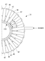
図10に示すように、冷却媒体供給ヘッダ31に設けられる板材34は、周方向に沿って複数に分割され、かつ、図15及び図16に示すように、配管110の径方向に沿って複数に分割されてもよい。板材34は、径方向に沿って、冷却媒体供給源側の分割部材34aと、配管110側の分割部材34bとで分割される。分割部材34a,34bは、例えばボルト39及びナット40によって互いに結合される。分割部材34bの分割部材34aに対する結合位置を変更することにより、配管110の配管径が異なる場合でも、板材34をすべて取り換えることなく、分割構造を有する板材34を伸縮させるだけで、冷却媒体供給ヘッダ31を設置することができる。分割部材34bは、図15に示すように、例えば扇形形状を有し、冷媒供給源側の周方向が長く、配管側の周方向が短い。
冷却媒体供給源側の分割部材34aと、配管110側の分割部材34bとは、ボルト締結のため、分割部材34aと分割部材34bの一方に配管110の径方向に長い長孔が形成され、他方に円形の孔が形成されてもよい。これにより、現地において、分割部材34bの設置位置、すなわち、板材34の伸縮長さを微調整できる。
分割部材34aと分割部材34bの結合方法に関し、図17に示すように、分割部材34aと分割部材34bの一方に、予め複数種類用意されたスペーサ43を嵌合可能な開口部44が形成されてもよい。図17(B)では、分割部材34bに開口部44が形成される場合について示している。スペーサ43は、図17(A)に示すように、種類ごとに配管110の径方向に沿ってボルト孔45の位置が異なるように形成されている。開口部44に嵌合されるスペーサ43は、ボルト孔45が配管110の径方向において適切な位置となるように選択される。これにより、スペーサ43を取り替えるだけで、板材34の伸縮長さを変更でき、かつ、分割部材34a,34b同士を確実に固定できる。
板材34は、冷却媒体供給源側で温度が低いのに対し、配管110は、内部に高温流体が流れることによって熱膨張するため、板材34の端部34Aに比べて、配管110の曲率半径が大きくなる。そのため、板材34の端部34Aの曲率半径は、低温時の配管110の曲率半径よりも大きくなるように、配管110の熱膨張をあらかじめ考慮して板材34を製造しておいてもよい。これにより、配管110の温度が上昇して熱膨張し、配管110の曲率半径が大きくなったとき、板材34の端部34Aと配管110との間に形成される隙間を低減できる。
また、分割構造を有する板材34の分割部材34bは、常に配管110の径方向であって、配管110側に付勢される構成を有してもよい。これにより、配管110の内部に高温流体が流れることによって、配管110が熱膨張して曲率半径が大きくなったときも、板材34の端部34Aは、配管110の外周面に追従して移動できる。この場合、図16に示すように、冷却媒体流出ノズル33の流出口の開口面積が維持されるように、板材34の端部34Aと配管110の外周面の間にはスペーサ46が設けられる。スペーサ46は、周方向に沿って間隔を空けて複数箇所に設置される。
板材34の分割部材34bを配管110側に付勢する手段としては、分割部材34bを配管110側に押し付けるばね部材、分割部材34bの外周側端部34b1(図16参照)を締め付けるリング状の伸縮性を有するバンド部材などがある。または、図16に示した分割部材34bの端部34Aに設置されるスペーサ46に磁石が設けられることによって、分割部材34bを配管110側に付勢するようにしてもよい。
また、上述した実施形態や変形例では、図6に示すように、冷却媒体供給ヘッダ31及び板材34は、リング形状を有し、配管110の周方向において、連続して形成された一体もの、又は、図10に示すように、複数に分割されて組み合わされるものについて説明した。本発明は、この例に限定されず、例えば、図18及び図19に示すように、冷却媒体供給ヘッダ31について、複数のヘッダユニット47と、ヘッダユニット47間を連結する複数の蛇腹ダクト48から構成されるとしてもよい。蛇腹ダクト48は、伸縮部の一例である。ヘッダユニット47と蛇腹ダクト48は交互に連結される。
複数のヘッダユニット47と複数の蛇腹ダクト48は、直線方向に連結可能である。そして、複数のヘッダユニット47と複数の蛇腹ダクト48は、配管110の外周長さに合わせて組合せ数が決定され、長さが調整される。連結されたヘッダユニット47と蛇腹ダクト48は、配管110の外周に沿って巻かれた後、一端部と他端部が連結されてリング形状とされる。
予め想定される最大径の配管110に応じて、ヘッダユニット47と蛇腹ダクト48の個数を予め用意しておくとよい。
予め想定される最大径の配管110に応じて、ヘッダユニット47と蛇腹ダクト48の個数を予め用意しておくとよい。
これにより、例えば電力需要が高い時期に非破壊試験によって配管損傷リスクが高い部位が検出されるなど、迅速に損傷部位を冷却する必要性が生じた場合でも、冷却媒体供給ヘッダ31を迅速に製作し、当該部位を迅速に冷却することで、損傷した配管110を延命化しプラントの信頼性を向上することができる。
図19のように、各ヘッダユニット47は、ヘッダ部49と流出部14とを有する。配管110に接する流出部14側は、例えばステンレス鋼などの耐熱部材で形成され、常温に近いヘッダ部49側は例えばアルミニウム合金などの軽量部材で形成される。これにより、冷却媒体供給ヘッダ31全体の軽量化を図ることができる。ヘッダ部49と流出部14側は異種材料であるため、例えばかしめやリベット等によって連結される。
各ヘッダユニット47の流出部14は、例えば、それぞれのヘッダユニット47で側端面14aによって閉じた構造となっており、ヘッダ部49側が蛇腹ダクト48によって連結される。または、各ヘッダユニット47の流出部14についても、蛇腹ダクトによって連結され、互いに冷却媒体が流通可能な構造を有してもよい。ヘッダ部49側で連結される蛇腹ダクト48は、室温に近い条件下で配置されるため、金属製ではなくシート状の耐熱性を有する合成樹脂で作製されてもよい。
冷却媒体供給ヘッダ31及び板材34について、複数のヘッダユニット47と、ヘッダユニット47間を連結する複数の蛇腹ダクト48から構成されることによって、高温の配管110の外径が異なる場合でも、冷却媒体供給ヘッダ31の構造を変更することなく、簡易に配管110に取り付けることが可能になる。また、蛇腹ダクト48で連結されていることから、配管110の熱変形にも追従可能である。さらに、配管110の周方向に沿ってリング状に配置する冷却媒体供給ヘッダ31に適用するだけでなく、直線状に配置すれば、配管110の管軸方向に沿って配置する冷却媒体供給ヘッダ11にも適用可能である。
なお、本変形例では、蛇腹ダクト48を有する場合について説明したが、必ずしも蛇腹構造を有してなくてもよく、ヘッダユニット47間の間隔を調整可能な部材によって、ヘッダユニット47間が連結されていればよい。例えば、蛇腹ダクト48の代わりに、布製、金属製又はゴム製のシート部材が設けられてもよい。
[第2実施形態]
図20は、第2実施形態の高温配管の冷却装置を表す概略図、図21は、第2実施形態の高温配管の冷却装置の第1変形例を表す概略図である。なお、上述した第1実施形態と同様の機能を有する部材には、同一の符号を付して詳細な説明は省略する。
図20は、第2実施形態の高温配管の冷却装置を表す概略図、図21は、第2実施形態の高温配管の冷却装置の第1変形例を表す概略図である。なお、上述した第1実施形態と同様の機能を有する部材には、同一の符号を付して詳細な説明は省略する。
第2実施形態において、図20に示すように、高温配管の冷却装置50は、金属配管100における被冷却面104を冷却するものであり、冷却媒体供給ヘッダ51と、冷却媒体供給装置52と、冷却媒体流出ノズル53、フード200とを備えている。
冷却媒体供給ヘッダ51は、金属配管100の被冷却面104から放射による放熱を遮蔽しないように配置される。各冷却媒体供給ヘッダ51は、断熱材102の撤去部103における周方向の両側で、この断熱材102の外周面に載置されるように支持される。
各冷却媒体供給ヘッダ51は、断熱材102の撤去部103における周方向の両側に、冷却媒体流出ノズル53が対向するように設けられる。冷却媒体流出ノズル53は、冷却媒体供給ヘッダ51における撤去部103側で、この撤去部103が形成される断熱材102の端面に沿って配管100の外周面側に延出され、先端部が溶接部101に向くように配管100の外周面に対して傾斜している。そのため、各冷却媒体流出ノズル53は、流出口が対向するように配置され、冷却媒体を被冷却面104における溶接部101に向けて流出する。
冷却媒体供給装置52は、ファンもしくはブロアであって、各冷却媒体供給ヘッダ51に冷却媒体を供給する。冷却媒体供給装置52は、取込配管61が連結されると共に、各冷却媒体供給ヘッダ51まで供給配管62が連結される。そのため、冷却媒体供給装置52は、取込配管61から取り込んだ冷却媒体を供給配管62により各冷却媒体供給ヘッダ51に供給できる。
そのため、冷却媒体供給装置52を作動すると、取込配管61を通して冷却媒体を取り込み、供給配管62を通して各冷却媒体供給ヘッダ51に供給する。各冷却媒体供給ヘッダ51は、各冷却媒体流出ノズル53から被冷却面104の溶接部101に向けて冷却媒体を流出する。この結果、流出された冷却媒体により溶接部101を高い熱伝達率で冷却するので、冷却効率を向上できる。
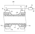
第1変形例において、図21に示すように冷却装置70は、金属配管110における被冷却面114を冷却するものであり、冷却媒体供給ヘッダ71と、冷却媒体供給装置72と、冷却媒体流出ノズル73、フード200とを備える。
冷却媒体供給ヘッダ71は、配管110の被冷却面114から放射による放熱を遮蔽しないように配置される。各冷却媒体供給ヘッダ71は、断熱材112の外周面に載置されるように支持される。
各冷却媒体供給ヘッダ71は、対向する側に冷却媒体流出ノズル73がそれぞれ対向するように設けられる。冷却媒体流出ノズル73は、冷却媒体供給ヘッダ71における撤去部113側で、この撤去部113が形成される断熱材112の端面に沿って配管110の外周面側に延出され、先端部が溶接部111へ向くように配管110の外周面に対して傾斜している。そのため、各冷却媒体流出ノズル73は、流出口が対向するように配置され、冷却媒体を被冷却面114における溶接部111に向けて流出する。
冷却媒体供給装置72は、ファンもしくはブロアであって、各冷却媒体供給ヘッダ71に冷却媒体を供給する。冷却媒体供給装置72は、取込配管81が連結されると共に、各冷却媒体供給ヘッダ71まで供給配管82が連結される。そのため、冷却媒体供給装置72は、取込配管81から取り込んだ冷却媒体を供給配管82により各冷却媒体供給ヘッダ71に供給できる。
そのため、冷却媒体供給装置72を作動すると、取込配管81を通して冷却媒体を取り込み、供給配管82を通して各冷却媒体供給ヘッダ71に供給する。各冷却媒体供給ヘッダ71は、各冷却媒体流出ノズル73から被冷却面114の溶接部111に向けて冷却媒体を流出し、流出された冷却媒体により溶接部111が高い熱伝達率で冷却される。
このように第2実施形態の高温配管の冷却装置にあっては、配管100,110における被冷却面104,114を冷却する高温配管の冷却装置50,70において、被冷却面104,114からの放射による放熱を遮蔽しないように配置される冷却媒体供給ヘッダ51,71と、冷却媒体供給ヘッダ51,71に冷却媒体を供給する冷却媒体供給装置52,72と、冷却媒体供給ヘッダ51,71の冷却媒体を被冷却面104,114に向けて流出する冷却媒体流出ノズル53,73とを備える。なお第2実施形態の高温配管の冷却装置では、冷却媒体供給ヘッダ51,71を被冷却面104,114に沿う両側に配置しているが、高温配管が小径管の場合には、冷却媒体供給ヘッダ51,71を片側のみに配置しても良い。
従って、冷却媒体供給装置52,72が冷却媒体供給ヘッダ51,71に冷却媒体を供給すると、この冷却媒体供給ヘッダ51,71に冷却媒体が供給され、冷却媒体供給ヘッダ51,71の冷却媒体が冷却媒体流出ノズル53,73から被冷却面104,114に向けて流出され、配管100,110の被冷却面104,114を高い熱伝達率で冷却する。このとき、冷却媒体供給ヘッダ51,71が被冷却面104,114からの放射による放熱を遮蔽しないように配置されるため、被冷却面104,114の外側が開放空間を持つ。そのように放射による放熱量を最大化するので冷却媒体量を抑制し、配管100,110を効果的に冷却できる。
第2実施形態の高温配管の冷却装置では、冷却媒体流出ノズル53,73は、冷却媒体を溶接部101,111に向けて流出する。従って、冷却媒体がクリープ損傷リスクが高い溶接部101,111を高い熱伝達率で冷却するので、被冷却面104,114を効率的に冷却できる。
なお、上述した実施形態では、冷却媒体流出ノズル13,33が冷却媒体を被冷却面104,114に沿って流出したり、冷却媒体流出ノズル53,73が冷却媒体を溶接部101,111に向けて流出したりするように構成したが、この構成に限定されるものではない。例えば、冷却媒体流出ノズルが冷却媒体を被冷却面104,114に向けて流出し、溶接部101,111に沿わせるように供給しても良い。
また、上述した実施形態では、周囲の気温や被冷却面温度に応じて冷却媒体供給ヘッダへの冷却媒体量を制御するように構成したが、風速や雨天などの天候を考慮して冷却媒体供給ヘッダへの冷却媒体量を制御してもよい。
また、上述した実施形態では、冷却媒体を空気としたが、窒素ガスなどの不活性ガスとしてもよい。
10 :冷却装置
11 :冷却媒体供給ヘッダ
12 :冷却媒体供給装置
13 :冷却媒体流出ノズル
14 :流出部
14a :側端面
21 :取込配管
22 :供給配管
23 :第1温度センサ
24 :第2温度センサ
25 :制御装置
30 :冷却装置
31 :冷却媒体供給ヘッダ
31A :分割部材
31B :分割部材
31C :分割部材
31a :フランジ部
32 :冷却媒体供給装置
33 :冷却媒体流出ノズル
34 :板材
34A :端部
34a :分割部材
34b :分割部材
34b1:外周側端部
35 :スリット
36 :金属箔
37 :サポート材
37a :第1部材
37b :第2部材
37c :ワイヤ材
38 :曲面部
39 :ボルト
40 :ナット
41 :取込配管
42 :供給配管
43 :スペーサ
44 :開口部
45 :ボルト孔
46 :スペーサ
47 :ヘッダユニット
48 :蛇腹ダクト
49 :ヘッダ部
50 :冷却装置
51 :冷却媒体供給ヘッダ
52 :冷却媒体供給装置
53 :冷却媒体流出ノズル
61 :取込配管
62 :供給配管
70 :冷却装置
71 :冷却媒体供給ヘッダ
72 :冷却媒体供給装置
73 :冷却媒体流出ノズル
81 :取込配管
82 :供給配管
100 :配管
101 :溶接部
102 :断熱材
103 :撤去部
104 :被冷却面
110 :配管
111 :溶接部
112 :断熱材
113 :撤去部
114 :被冷却面
200 :フード
H :流出口の高さ
L :冷却長さ
W :溶接部分
11 :冷却媒体供給ヘッダ
12 :冷却媒体供給装置
13 :冷却媒体流出ノズル
14 :流出部
14a :側端面
21 :取込配管
22 :供給配管
23 :第1温度センサ
24 :第2温度センサ
25 :制御装置
30 :冷却装置
31 :冷却媒体供給ヘッダ
31A :分割部材
31B :分割部材
31C :分割部材
31a :フランジ部
32 :冷却媒体供給装置
33 :冷却媒体流出ノズル
34 :板材
34A :端部
34a :分割部材
34b :分割部材
34b1:外周側端部
35 :スリット
36 :金属箔
37 :サポート材
37a :第1部材
37b :第2部材
37c :ワイヤ材
38 :曲面部
39 :ボルト
40 :ナット
41 :取込配管
42 :供給配管
43 :スペーサ
44 :開口部
45 :ボルト孔
46 :スペーサ
47 :ヘッダユニット
48 :蛇腹ダクト
49 :ヘッダ部
50 :冷却装置
51 :冷却媒体供給ヘッダ
52 :冷却媒体供給装置
53 :冷却媒体流出ノズル
61 :取込配管
62 :供給配管
70 :冷却装置
71 :冷却媒体供給ヘッダ
72 :冷却媒体供給装置
73 :冷却媒体流出ノズル
81 :取込配管
82 :供給配管
100 :配管
101 :溶接部
102 :断熱材
103 :撤去部
104 :被冷却面
110 :配管
111 :溶接部
112 :断熱材
113 :撤去部
114 :被冷却面
200 :フード
H :流出口の高さ
L :冷却長さ
W :溶接部分
Claims (14)
- 高温配管における被冷却面の周囲に設置される高温配管の冷却装置において、
前記被冷却面から周囲への放射による放熱を遮蔽しない位置に配置されて冷却媒体を前記被冷却面に向けて流出する冷却媒体供給ヘッダと、
前記冷却媒体供給ヘッダに冷却媒体を供給する冷却媒体供給装置と、
を備えることを特徴とする高温配管の冷却装置。 - 前記被冷却面は、前記高温配管を被覆する断熱材の撤去部から露出した前記高温配管の露出表面であり、前記冷却媒体供給ヘッダは、前記被冷却面の外側に配置されることを特徴とする請求項1に記載の高温配管の冷却装置。
- 前記冷却媒体供給ヘッダは、前記断熱材の外面に支持されることを特徴とする請求項2に記載の高温配管の冷却装置。
- 前記冷却媒体供給ヘッダは、サポート部材によって、前記高温配管及び前記断熱材の外面に支持されることを特徴とする請求項2に記載の高温配管の冷却装置。
- 前記冷却媒体供給ヘッダの冷却媒体を前記被冷却面に向けて流出する冷却媒体流出ノズルが設けられることを特徴とする請求項1から請求項4のいずれか一項に記載の高温配管の冷却装置。
- 前記冷却媒体流出ノズルは、冷却媒体を前記被冷却面に沿って流出することを特徴とする請求項5に記載の高温配管の冷却装置。
- 前記被冷却面は、溶接部を含み、前記冷却媒体流出ノズルは、冷却媒体を前記溶接部に向けて流出することを特徴とする請求項5に記載の高温配管の冷却装置。
- 前記冷却媒体供給ヘッダは、
前記冷却媒体供給ヘッダの冷却媒体を前記被冷却面に向けて流出する冷却媒体流出口が設けられ、
前記高温配管を被覆する断熱材の撤去部に沿って設けられた板材を有し、
前記板材の前記高温配管側の端部と前記高温配管の表面によって前記冷却媒体流出口が形成されることを特徴とする請求項1から請求項4のいずれか一項に記載の高温配管の冷却装置。 - 前記冷却媒体供給ヘッダは、前記高温配管を被覆する断熱材の撤去部に沿って設けられた板材を有し、
前記板材は、前記高温配管側から外側へ向けてスリットが形成されていることを特徴とする請求項1から請求項4のいずれか一項に記載の高温配管の冷却装置。 - 前記冷却媒体供給ヘッダは、前記高温配管を被覆する断熱材の撤去部に沿って設けられた板材を有し、
前記板材は、前記高温配管の周方向に沿って複数に分割された分割部材を組み合わせて構成されることを特徴とする請求項1から請求項4のいずれか一項に記載の高温配管の冷却装置。 - 前記冷却媒体供給ヘッダは、前記高温配管を被覆する断熱材の撤去部に沿って設けられた板材を有し、
前記板材は、前記高温配管に沿って複数に分割された分割部材を組み合わせて構成され、前記板材における前記高温配管側の端部の位置が調整可能であることを特徴とする請求項1から請求項4のいずれか一項に記載の高温配管の冷却装置。 - 前記冷却媒体供給ヘッダは、
前記冷却媒体が流通しつつ、前記冷却媒体を前記被冷却面に向けて流出する複数のヘッダユニットと、
二つの前記ヘッダユニット間に設けられる伸縮部と、
を有し、
前記ヘッダユニットと前記伸縮部が交互に連結されていることを特徴とする請求項1から請求項4のいずれか一項に記載の高温配管の冷却装置。 - 前記冷却媒体供給装置が前記冷却媒体供給ヘッダに供給する冷却媒体の温度を計測する温度センサと、前記温度センサが計測した冷却媒体の温度に応じて前記冷却媒体流出ノズル又は前記冷却媒体流出口が前記被冷却面に向けて流出する冷却媒体の流出量を制御する制御装置が設けられることを特徴とする請求項5又は8に記載の高温配管の冷却装置。
- 前記被冷却面の温度を計測する温度センサと、前記温度センサが計測した前記被冷却面の温度に応じて前記冷却媒体流出ノズル又は前記冷却媒体流出口が前記被冷却面に向けて流出する冷却媒体の流出量を制御する制御装置が設けられることを特徴とする請求項5又は8に記載の高温配管の冷却装置。
Priority Applications (4)
| Application Number | Priority Date | Filing Date | Title |
|---|---|---|---|
| CN201780018211.XA CN109073131B (zh) | 2016-03-24 | 2017-02-23 | 高温配管的冷却装置 |
| US16/080,727 US20190056052A1 (en) | 2016-03-24 | 2017-02-23 | Cooling device for high temperature pipe |
| JP2018507154A JP6615985B2 (ja) | 2016-03-24 | 2017-02-23 | 高温配管の冷却装置 |
| DE112017001485.9T DE112017001485T5 (de) | 2016-03-24 | 2017-02-23 | Kühlvorrichtung für Hochtemperaturrohr |
Applications Claiming Priority (2)
| Application Number | Priority Date | Filing Date | Title |
|---|---|---|---|
| JP2016-060657 | 2016-03-24 | ||
| JP2016060657 | 2016-03-24 |
Publications (1)
| Publication Number | Publication Date |
|---|---|
| WO2017163746A1 true WO2017163746A1 (ja) | 2017-09-28 |
Family
ID=59901257
Family Applications (1)
| Application Number | Title | Priority Date | Filing Date |
|---|---|---|---|
| PCT/JP2017/006865 Ceased WO2017163746A1 (ja) | 2016-03-24 | 2017-02-23 | 高温配管の冷却装置 |
Country Status (5)
| Country | Link |
|---|---|
| US (1) | US20190056052A1 (ja) |
| JP (1) | JP6615985B2 (ja) |
| CN (1) | CN109073131B (ja) |
| DE (1) | DE112017001485T5 (ja) |
| WO (1) | WO2017163746A1 (ja) |
Cited By (1)
| Publication number | Priority date | Publication date | Assignee | Title |
|---|---|---|---|---|
| JP2020139692A (ja) * | 2019-02-28 | 2020-09-03 | 三菱日立パワーシステムズ株式会社 | 金属壁部の冷却構造及び金属壁部の冷却方法 |
Families Citing this family (1)
| Publication number | Priority date | Publication date | Assignee | Title |
|---|---|---|---|---|
| JP6720125B2 (ja) * | 2017-09-22 | 2020-07-08 | 三菱日立パワーシステムズ株式会社 | 金属壁部冷却方法 |
Citations (7)
| Publication number | Priority date | Publication date | Assignee | Title |
|---|---|---|---|---|
| JPS55150288U (ja) * | 1979-04-09 | 1980-10-29 | ||
| EP0160225A2 (de) * | 1984-04-28 | 1985-11-06 | BASF Aktiengesellschaft | Verfahren zur Wärmeabfuhr aus einem bzw. zur Wärmezufuhr in ein senkrecht angeordnetes Rohr |
| JPH05231586A (ja) * | 1991-12-27 | 1993-09-07 | Nkk Corp | 多重構造のダクト |
| JP2015045619A (ja) * | 2013-08-29 | 2015-03-12 | 三菱日立パワーシステムズ株式会社 | 高温配管の延命方法及び高温配管の延命化構造、高温配管のメタル温度の制御方法 |
| US9115830B1 (en) * | 2012-02-14 | 2015-08-25 | Badger Ridge Industries, LLC | Jacketed line coupling |
| WO2016076011A1 (ja) * | 2014-11-11 | 2016-05-19 | 三菱日立パワーシステムズ株式会社 | 冷却装置 |
| US20160160759A1 (en) * | 2014-12-08 | 2016-06-09 | Airbus Operations (Sas) | Antifreeze system for a pipework |
Family Cites Families (4)
| Publication number | Priority date | Publication date | Assignee | Title |
|---|---|---|---|---|
| GB586226A (en) * | 1944-12-18 | 1947-03-11 | Thomas Nicholas Young | Apparatus for temporarily stopping pipes |
| US3997374A (en) * | 1972-07-07 | 1976-12-14 | Hughes Tool Company | Heat treatment of welds |
| JPH1122893A (ja) * | 1997-07-03 | 1999-01-26 | Hitachi Ltd | 配管等の熱疲労損傷防止方法及び装置 |
| FR2975748B1 (fr) * | 2011-05-23 | 2013-06-21 | Itp Sa | Dispositif sous-marin de transport d'hydrocarbures et de regulation de leur temperature |
-
2017
- 2017-02-23 WO PCT/JP2017/006865 patent/WO2017163746A1/ja not_active Ceased
- 2017-02-23 JP JP2018507154A patent/JP6615985B2/ja active Active
- 2017-02-23 CN CN201780018211.XA patent/CN109073131B/zh active Active
- 2017-02-23 US US16/080,727 patent/US20190056052A1/en not_active Abandoned
- 2017-02-23 DE DE112017001485.9T patent/DE112017001485T5/de active Pending
Patent Citations (7)
| Publication number | Priority date | Publication date | Assignee | Title |
|---|---|---|---|---|
| JPS55150288U (ja) * | 1979-04-09 | 1980-10-29 | ||
| EP0160225A2 (de) * | 1984-04-28 | 1985-11-06 | BASF Aktiengesellschaft | Verfahren zur Wärmeabfuhr aus einem bzw. zur Wärmezufuhr in ein senkrecht angeordnetes Rohr |
| JPH05231586A (ja) * | 1991-12-27 | 1993-09-07 | Nkk Corp | 多重構造のダクト |
| US9115830B1 (en) * | 2012-02-14 | 2015-08-25 | Badger Ridge Industries, LLC | Jacketed line coupling |
| JP2015045619A (ja) * | 2013-08-29 | 2015-03-12 | 三菱日立パワーシステムズ株式会社 | 高温配管の延命方法及び高温配管の延命化構造、高温配管のメタル温度の制御方法 |
| WO2016076011A1 (ja) * | 2014-11-11 | 2016-05-19 | 三菱日立パワーシステムズ株式会社 | 冷却装置 |
| US20160160759A1 (en) * | 2014-12-08 | 2016-06-09 | Airbus Operations (Sas) | Antifreeze system for a pipework |
Cited By (2)
| Publication number | Priority date | Publication date | Assignee | Title |
|---|---|---|---|---|
| JP2020139692A (ja) * | 2019-02-28 | 2020-09-03 | 三菱日立パワーシステムズ株式会社 | 金属壁部の冷却構造及び金属壁部の冷却方法 |
| JP7274890B2 (ja) | 2019-02-28 | 2023-05-17 | 三菱重工業株式会社 | 金属壁部の冷却構造及び金属壁部の冷却方法 |
Also Published As
| Publication number | Publication date |
|---|---|
| JP6615985B2 (ja) | 2019-12-04 |
| CN109073131B (zh) | 2020-08-25 |
| CN109073131A (zh) | 2018-12-21 |
| US20190056052A1 (en) | 2019-02-21 |
| DE112017001485T5 (de) | 2018-12-06 |
| JPWO2017163746A1 (ja) | 2019-01-10 |
Similar Documents
| Publication | Publication Date | Title |
|---|---|---|
| US10731509B2 (en) | Compliant seal component and associated method | |
| US7270175B2 (en) | Extended impingement cooling device and method | |
| US8157511B2 (en) | Turbine shroud gas path duct interface | |
| US8510945B2 (en) | Method of mounting a heat exchanger in a gas turbine engine assembly | |
| EP2534340B1 (en) | Turbine vane hollow inner rail | |
| JP6289347B2 (ja) | 冷却装置 | |
| US7708518B2 (en) | Turbine blade tip clearance control | |
| US20090053042A1 (en) | Method and apparatus for clearance control of turbine blade tip | |
| US20110146944A1 (en) | Heat Exchanger Mounting Assembly | |
| JP4526976B2 (ja) | ターボ機械の高圧タービンのリングスペーサセクタを軸方向に保持するための装置 | |
| JP6615985B2 (ja) | 高温配管の冷却装置 | |
| US9739412B2 (en) | Method of extending life expectancy of high-temperature piping and life expectancy extension structure of high-temperature piping | |
| US8033719B2 (en) | Gas turbine with protective sheath for a probe and method for protecting an instrument lead which is laid in a protective sheath | |
| JP2015052298A (ja) | 蒸気タービン設備及びその運用方法 | |
| US10294800B2 (en) | Gas turbine blade | |
| US11698003B2 (en) | Cooling device for a turbine of a turbomachine | |
| JP6918662B2 (ja) | 高温配管の冷却構造及び高温配管の冷却システム | |
| JP2016160959A (ja) | 高温配管の冷却治具,冷却装置及びその設置方法 |
Legal Events
| Date | Code | Title | Description |
|---|---|---|---|
| WWE | Wipo information: entry into national phase |
Ref document number: 2018507154 Country of ref document: JP |
|
| 121 | Ep: the epo has been informed by wipo that ep was designated in this application |
Ref document number: 17769792 Country of ref document: EP Kind code of ref document: A1 |
|
| 122 | Ep: pct application non-entry in european phase |
Ref document number: 17769792 Country of ref document: EP Kind code of ref document: A1 |