WO2017163715A1 - Biocapteur haute sensibilité et procédé de production de celui-ci - Google Patents
Biocapteur haute sensibilité et procédé de production de celui-ci Download PDFInfo
- Publication number
- WO2017163715A1 WO2017163715A1 PCT/JP2017/006306 JP2017006306W WO2017163715A1 WO 2017163715 A1 WO2017163715 A1 WO 2017163715A1 JP 2017006306 W JP2017006306 W JP 2017006306W WO 2017163715 A1 WO2017163715 A1 WO 2017163715A1
- Authority
- WO
- WIPO (PCT)
- Prior art keywords
- electrode
- biosensor
- substance
- polymer layer
- polymerization
- Prior art date
Links
Images


Classifications
-
- G—PHYSICS
- G01—MEASURING; TESTING
- G01N—INVESTIGATING OR ANALYSING MATERIALS BY DETERMINING THEIR CHEMICAL OR PHYSICAL PROPERTIES
- G01N27/00—Investigating or analysing materials by the use of electric, electrochemical, or magnetic means
- G01N27/26—Investigating or analysing materials by the use of electric, electrochemical, or magnetic means by investigating electrochemical variables; by using electrolysis or electrophoresis
- G01N27/28—Electrolytic cell components
- G01N27/30—Electrodes, e.g. test electrodes; Half-cells
- G01N27/327—Biochemical electrodes, e.g. electrical or mechanical details for in vitro measurements
- G01N27/3275—Sensing specific biomolecules, e.g. nucleic acid strands, based on an electrode surface reaction
- G01N27/3278—Sensing specific biomolecules, e.g. nucleic acid strands, based on an electrode surface reaction involving nanosized elements, e.g. nanogaps or nanoparticles
-
- G—PHYSICS
- G01—MEASURING; TESTING
- G01N—INVESTIGATING OR ANALYSING MATERIALS BY DETERMINING THEIR CHEMICAL OR PHYSICAL PROPERTIES
- G01N27/00—Investigating or analysing materials by the use of electric, electrochemical, or magnetic means
- G01N27/26—Investigating or analysing materials by the use of electric, electrochemical, or magnetic means by investigating electrochemical variables; by using electrolysis or electrophoresis
- G01N27/403—Cells and electrode assemblies
- G01N27/414—Ion-sensitive or chemical field-effect transistors, i.e. ISFETS or CHEMFETS
-
- G—PHYSICS
- G01—MEASURING; TESTING
- G01N—INVESTIGATING OR ANALYSING MATERIALS BY DETERMINING THEIR CHEMICAL OR PHYSICAL PROPERTIES
- G01N27/00—Investigating or analysing materials by the use of electric, electrochemical, or magnetic means
- G01N27/02—Investigating or analysing materials by the use of electric, electrochemical, or magnetic means by investigating impedance
- G01N27/04—Investigating or analysing materials by the use of electric, electrochemical, or magnetic means by investigating impedance by investigating resistance
- G01N27/12—Investigating or analysing materials by the use of electric, electrochemical, or magnetic means by investigating impedance by investigating resistance of a solid body in dependence upon absorption of a fluid; of a solid body in dependence upon reaction with a fluid, for detecting components in the fluid
- G01N27/125—Composition of the body, e.g. the composition of its sensitive layer
- G01N27/126—Composition of the body, e.g. the composition of its sensitive layer comprising organic polymers
-
- G—PHYSICS
- G01—MEASURING; TESTING
- G01N—INVESTIGATING OR ANALYSING MATERIALS BY DETERMINING THEIR CHEMICAL OR PHYSICAL PROPERTIES
- G01N27/00—Investigating or analysing materials by the use of electric, electrochemical, or magnetic means
- G01N27/26—Investigating or analysing materials by the use of electric, electrochemical, or magnetic means by investigating electrochemical variables; by using electrolysis or electrophoresis
- G01N27/28—Electrolytic cell components
- G01N27/30—Electrodes, e.g. test electrodes; Half-cells
- G01N27/327—Biochemical electrodes, e.g. electrical or mechanical details for in vitro measurements
- G01N27/3271—Amperometric enzyme electrodes for analytes in body fluids, e.g. glucose in blood
- G01N27/3272—Test elements therefor, i.e. disposable laminated substrates with electrodes, reagent and channels
-
- G—PHYSICS
- G01—MEASURING; TESTING
- G01N—INVESTIGATING OR ANALYSING MATERIALS BY DETERMINING THEIR CHEMICAL OR PHYSICAL PROPERTIES
- G01N27/00—Investigating or analysing materials by the use of electric, electrochemical, or magnetic means
- G01N27/26—Investigating or analysing materials by the use of electric, electrochemical, or magnetic means by investigating electrochemical variables; by using electrolysis or electrophoresis
- G01N27/28—Electrolytic cell components
- G01N27/30—Electrodes, e.g. test electrodes; Half-cells
- G01N27/327—Biochemical electrodes, e.g. electrical or mechanical details for in vitro measurements
- G01N27/3271—Amperometric enzyme electrodes for analytes in body fluids, e.g. glucose in blood
- G01N27/3273—Devices therefor, e.g. test element readers, circuitry
-
- G—PHYSICS
- G01—MEASURING; TESTING
- G01N—INVESTIGATING OR ANALYSING MATERIALS BY DETERMINING THEIR CHEMICAL OR PHYSICAL PROPERTIES
- G01N27/00—Investigating or analysing materials by the use of electric, electrochemical, or magnetic means
- G01N27/26—Investigating or analysing materials by the use of electric, electrochemical, or magnetic means by investigating electrochemical variables; by using electrolysis or electrophoresis
- G01N27/28—Electrolytic cell components
- G01N27/30—Electrodes, e.g. test electrodes; Half-cells
- G01N27/327—Biochemical electrodes, e.g. electrical or mechanical details for in vitro measurements
- G01N27/3275—Sensing specific biomolecules, e.g. nucleic acid strands, based on an electrode surface reaction
-
- G—PHYSICS
- G01—MEASURING; TESTING
- G01N—INVESTIGATING OR ANALYSING MATERIALS BY DETERMINING THEIR CHEMICAL OR PHYSICAL PROPERTIES
- G01N27/00—Investigating or analysing materials by the use of electric, electrochemical, or magnetic means
- G01N27/26—Investigating or analysing materials by the use of electric, electrochemical, or magnetic means by investigating electrochemical variables; by using electrolysis or electrophoresis
- G01N27/403—Cells and electrode assemblies
- G01N27/414—Ion-sensitive or chemical field-effect transistors, i.e. ISFETS or CHEMFETS
- G01N27/4145—Ion-sensitive or chemical field-effect transistors, i.e. ISFETS or CHEMFETS specially adapted for biomolecules, e.g. gate electrode with immobilised receptors
-
- G—PHYSICS
- G01—MEASURING; TESTING
- G01N—INVESTIGATING OR ANALYSING MATERIALS BY DETERMINING THEIR CHEMICAL OR PHYSICAL PROPERTIES
- G01N27/00—Investigating or analysing materials by the use of electric, electrochemical, or magnetic means
- G01N27/26—Investigating or analysing materials by the use of electric, electrochemical, or magnetic means by investigating electrochemical variables; by using electrolysis or electrophoresis
- G01N27/416—Systems
-
- G—PHYSICS
- G01—MEASURING; TESTING
- G01N—INVESTIGATING OR ANALYSING MATERIALS BY DETERMINING THEIR CHEMICAL OR PHYSICAL PROPERTIES
- G01N33/00—Investigating or analysing materials by specific methods not covered by groups G01N1/00 - G01N31/00
- G01N33/02—Food
-
- G—PHYSICS
- G01—MEASURING; TESTING
- G01N—INVESTIGATING OR ANALYSING MATERIALS BY DETERMINING THEIR CHEMICAL OR PHYSICAL PROPERTIES
- G01N33/00—Investigating or analysing materials by specific methods not covered by groups G01N1/00 - G01N31/00
- G01N33/48—Biological material, e.g. blood, urine; Haemocytometers
- G01N33/483—Physical analysis of biological material
- G01N33/487—Physical analysis of biological material of liquid biological material
- G01N33/48707—Physical analysis of biological material of liquid biological material by electrical means
-
- G—PHYSICS
- G01—MEASURING; TESTING
- G01N—INVESTIGATING OR ANALYSING MATERIALS BY DETERMINING THEIR CHEMICAL OR PHYSICAL PROPERTIES
- G01N33/00—Investigating or analysing materials by specific methods not covered by groups G01N1/00 - G01N31/00
- G01N33/48—Biological material, e.g. blood, urine; Haemocytometers
- G01N33/50—Chemical analysis of biological material, e.g. blood, urine; Testing involving biospecific ligand binding methods; Immunological testing
- G01N33/53—Immunoassay; Biospecific binding assay; Materials therefor
- G01N33/543—Immunoassay; Biospecific binding assay; Materials therefor with an insoluble carrier for immobilising immunochemicals
- G01N33/54366—Apparatus specially adapted for solid-phase testing
- G01N33/54373—Apparatus specially adapted for solid-phase testing involving physiochemical end-point determination, e.g. wave-guides, FETS, gratings
- G01N33/5438—Electrodes
-
- G—PHYSICS
- G01—MEASURING; TESTING
- G01N—INVESTIGATING OR ANALYSING MATERIALS BY DETERMINING THEIR CHEMICAL OR PHYSICAL PROPERTIES
- G01N33/00—Investigating or analysing materials by specific methods not covered by groups G01N1/00 - G01N31/00
- G01N33/48—Biological material, e.g. blood, urine; Haemocytometers
- G01N33/50—Chemical analysis of biological material, e.g. blood, urine; Testing involving biospecific ligand binding methods; Immunological testing
- G01N33/66—Chemical analysis of biological material, e.g. blood, urine; Testing involving biospecific ligand binding methods; Immunological testing involving blood sugars, e.g. galactose
-
- G—PHYSICS
- G01—MEASURING; TESTING
- G01N—INVESTIGATING OR ANALYSING MATERIALS BY DETERMINING THEIR CHEMICAL OR PHYSICAL PROPERTIES
- G01N2610/00—Assays involving self-assembled monolayers [SAMs]
Definitions
- the present invention relates to a biosensor for detecting a detection target substance in a test sample.
- a biosensor recognizes external information (for example, chemical elements) as some physical signal by utilizing the excellent molecular discrimination power of living organisms, and has various principles and measurement objects. More specifically, a biosensor is a type of chemical sensor that uses a chemical substance as a measurement target. The biosensor is a molecular identification element that recognizes only the measurement target substance, and a physical signal such as an electrical signal indicating that the information is recognized. And a signal conversion element for converting the signal into the signal. In general, biosensors such as enzymes, antibodies, DNA, cells, microorganisms, and compounds that capture biomolecules are used for the molecular identification element, so these sensors are called biosensors.
- an ordinary electronic device or chemical sensor such as an electrode, thermistor, crystal resonator, surface plasmon resonance, or semiconductor element is used.
- a field effect transistor FET
- Research on the biosensor used has become active.
- biosensors using FETs when a molecular identification element recognizes a chemical substance to be measured, physical changes such as heat, mass, and charge, and chemical changes such as decomposition of the target substance and generation of the substance occur. The change is converted into an electric signal by the FET which is a signal conversion element, and the target substance is measured.
- Biosensors using FETs can (1) be able to electrically detect charges inherent to ions and molecules, (2) do not require time and effort until measurement, (3) enable real-time measurement, (4) non-measurement It has features such as labeling and non-invasive electrical measurement, and (5) miniaturization and integration by semiconductor microfabrication technology.
- the biosensor described in Patent Document 1 was an epoch-making invention in that a trace amount of a measurement target substance contained in a body fluid can be measured.
- various substances other than the measurement target substance are contained in the body fluid, in practical use of such a biosensor, not only the detection sensitivity for the measurement target substance is increased, but also There was a need to prevent false detection (ie, increase detection specificity).
- the present inventors allow substantially all substances other than the detection target substance to interact with the gate electrode. It was found that it becomes possible to prevent.
- the molecular template polymer refers to a polymer in which a “molecular template” having a structure complementary to the molecular structure of the detection target substance is formed on the polymer surface or in the polymer by a predetermined production method. Only the substance to be detected can be incorporated into the molecular template.
- the present inventors have further studied for the practical application of a biosensor in which a molecular template polymer is applied to a gate electrode. Then, the present inventors have found that a biosensor in which a molecular template polymer produced by a simple method is applied to a gate electrode, although the specificity to a detection target substance is improved as compared with the prior art, the molecular template polymer A new technical problem was encountered in that the detection sensitivity and detection stability for the detection target substance were slightly reduced by the thickness of the layer.
- the inventors control the film thickness of the molecular template polymer layer applied to the gate electrode by applying the polymer control technology mainly used in the field of polymer chemistry to this technical field.
- the molecular template polymer layer can be made an ultrathin film layer.
- a gate electrode having an ultra-thin molecular template polymer layer has not only detection specificity for a detection target substance but also extremely high detection sensitivity (see also the results of Examples of the present application).
- the molecular template polymer layer applied to the gate electrode is an ultra-thin film layer, so that the time from when the device is energized until the potential of the gate electrode surface is stabilized (that is, measured) The time from when the device is turned on until the device is ready to start measurement) has been greatly reduced, and the time from the start of measurement to the end of measurement has also been greatly reduced (in the embodiment of this application). See also results).
- the biosensor of the present invention is a device that has both high detection sensitivity and detection specificity for a detection target substance, and is excellent in practicality.
- the present invention includes an identification substance that can bind to a detection target substance, and an electrode that charges a charge of the identification substance, and is generated by binding the detection target substance to the identification substance.
- a polymer layer in which a molecular template having a structure complementary to the molecular structure of the detection target substance is formed on all or part of the surface of the electrode is formed on all or part of the surface of the electrode.
- the present invention relates to a biosensor, wherein the polymer layer contains the identification substance, and the polymer layer is an ultrathin film layer.
- the ultra thin film layer is a thin film layer having a thickness of 1 ⁇ m or less.
- the polymer layer is (A): A monomer solution containing one or a plurality of types of monomers, the detection target substance, and the identification substance is polymerized on all or a part of the surface of the electrode, whereby all or one of the surfaces of the electrode is polymerized. Forming a polymer layer that is an ultra-thin layer on the part; and (B): After the step (a), by removing the detection target substance from the polymer layer, forming a molecular template having a structure complementary to the molecular structure of the detection target substance in the polymer layer , It is formed by the method containing.
- the polymerization of the monomer solution is a living radical polymerization or an electrolytic polymerization.
- the living radical polymerization is atom transfer radical polymerization (ATRP), reversible addition-cleavage chain transfer polymerization (RAFT), or nitroxide-mediated polymerization (NMP). It is characterized by.
- the living radical polymerization is atom transfer radical polymerization (ATRP), and prior to the step (a), the polymerization initiating molecules are preliminarily formed on all or part of the surface of the electrode. It is characterized by being connected.
- ATRP atom transfer radical polymerization
- a monomer solution containing one or more types of monomers, the detection target substance, and the identification substance is applied to the surface of the electrode using spin coating. And a polymer layer of an ultrathin film layer is formed on all or part of the surface of the electrode by polymerizing the applied monomer solution.
- the electrode is a gold electrode, a silver electrode, a copper electrode, or a platinum electrode.
- the monomer solution comprises an acrylamide derivative, a methacrylamide derivative, an acrylate derivative, a methacrylate derivative, acrylonitrile, 2-vinylpyridine, 4-vinylpyridine, N-vinyl-2-pyrrolidone, and acetic acid. It contains at least one monomer selected from the group consisting of vinyl.
- the electrode is electrically connected to a gate insulating film of a field effect transistor.
- the electrode is disposed away from the field effect transistor, and the electrode is connected to another metal electrode provided on the gate insulating film and a wiring, It is electrically connected to the gate insulating film.
- the electrode is placed directly on the gate insulating film, thereby being electrically connected to the gate insulating film.
- the detection target substance is a substance derived from a living body, a substance in the environment, or a substance in food.
- the living body-derived substance is a body fluid-derived substance.
- the body fluid is a group consisting of blood, lymph fluid, tissue fluid, body cavity fluid, digestive fluid, sweat, tears, nasal discharge, saliva, urine, semen, vaginal fluid, amniotic fluid, and milk. It is selected from these.
- another embodiment of the present invention is an electrode used in a biosensor, wherein the biosensor detects a change in charge density of the electrode caused by binding of a detection target substance to an identification substance.
- a sensor and the electrode is an electrode that charges a charge of the identification substance that can bind to the detection target substance, and the whole or a part of the surface of the electrode is complementary to a molecular structure of the detection target substance.
- the present invention relates to an electrode, in which a polymer layer having a molecular template having a typical structure is formed, the polymer layer includes the identification substance, and the polymer layer is an ultrathin film layer.
- Another embodiment of the present invention is a method of manufacturing an electrode for use in a biosensor, the biosensor comprising a change in charge density of the electrode caused by binding of a substance to be detected to an identification substance.
- the electrode is an electrode that charges the charge of the identification substance that can bind to the detection target substance,
- the method (A): by polymerizing a monomer solution containing one or more types of monomers, the substance to be detected, and the identification substance on all or part of the surface of the electrode, Forming a polymer layer that is an ultra-thin layer in part; and (B): After the step (a), by removing the detection target substance from the polymer layer, forming a molecular template having a structure complementary to the molecular structure of the detection target substance in the polymer layer And a method comprising:
- the living radical polymerization is atom transfer radical polymerization (ATRP), and prior to the step (a), the polymerization initiating molecules are preliminarily formed on all or part of the surface of the electrode. It is characterized by including the process to combine.
- ATRP atom transfer radical polymerization
- a monomer solution containing one or more types of monomers, the detection target substance, and the identification substance is applied to the electrode using spin coating. It is a step of forming a polymer layer of an ultra-thin film layer on all or part of the surface of the electrode by applying to all or part of the surface and polymerizing the applied monomer solution.
- FIG. 1 is a schematic diagram showing a schematic configuration of a glucose sensor according to an embodiment of the present invention.
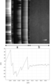
- FIG. 2 shows the results of measuring the film thickness of the polymer layer produced by the method of Production Example 1 with an atomic force microscope.
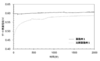
- FIG. 3 is a graph comparing the time from the start of energization to the stabilization of the gate surface potential in the apparatus of Production Example 1 or Comparative Production Example 1.
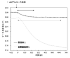
- FIG. 4 shows changes in the gate surface potential when a glucose solution is added in the apparatus of Production Example 1 or Comparative Production Example 1.
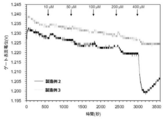
- FIG. 5 is a graph comparing detection of low-concentration glucose in the apparatus of Production Example 2 or Production Example 3.
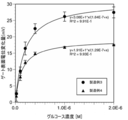
- FIG. 6 is a graph comparing detection of low-concentration glucose in the devices of Production Example 4 and Production Example 5.
- FIG. 1 is a schematic diagram showing a schematic configuration of a glucose sensor according to an embodiment of the present invention.
- FIG. 2 shows the results of measuring the film thickness of the polymer layer produced by the method of Production Example 1 with an atomic force
- FIG. 7 is a graph showing the amount of change in the gate surface potential when each concentration of glucose is added in the devices of Production Example 4 and Production Example 5.
- FIG. 8 is a graph comparing detection of low-concentration dopamine in the apparatus of Production Example 6.
- FIG. 9 is a graph showing the amount of change in gate surface potential when each concentration of dopamine is added in the apparatus of Production Example 6.
- the biosensor of the present invention detects an electrical change caused by the binding between a detection target substance and an identification substance that can specifically or selectively bind to the detection target substance as a change in the charge density of the electrode. Based on the basic principle (details will be described later).
- the “detection target substance” in the present invention is not limited as long as it can produce a molecular template polymer corresponding to the substance, and those skilled in the art can detect various substances based on common general technical knowledge.
- the biosensor of the present invention can be used for detection of a very small amount of substance in various test samples.
- a biological substance, an environmental substance, or a food The substance in it can be detected.
- the present invention can be detected even if the concentration of the detection target substance in the test sample is extremely low.
- body fluid blood, lymph, tissue fluid, body cavity fluid, digestive fluid, sweat, tears, nasal discharge, saliva, urine
- Semen vaginal fluid, amniotic fluid, milk, etc.
- substances in body fluid include, for example, body fluid components (for example, alkaline phosphatase, AST, ALT, lactate dehydrogenase, leucine aminopeptidase, ⁇ -GTP, creatine kinase, cholinesterase, bilirubin, bile acid, albumin, urea nitrogen Creatinine, uric acid, HDL cholesterol, LDL cholesterol, neutral fat, glucose, amylase, lipase, sodium, potassium, chlor, calcium, inorganic phosphorus, magnesium, zinc, iron, ferritin, C-reactive protein, ⁇ 2-microglobulin, Hemoglobin A1C, glycoalbumin, ammonia, various hormones, various neurotransmitters (for example, monoamines such as dopamine, adrenaline, noradrenaline, serotonin, melatonin, histamine; asparagi Components such as amino acids such as acid, glutamic acid, ⁇ -aminobutyric acid, g
- the “discriminating substance capable of binding to the detection target substance” in the present invention can be appropriately selected by those skilled in the art depending on the detection target substance, and the identification substance may specifically bind to the detection target substance.
- the substance may be a substance that can bind selectively to the substance to be detected.
- Examples of the “discriminating substance capable of binding to the detection target substance” in the present invention include, for example, a pair of substances known to cause specific or selective interaction (for example, glucose and phenylboronic acid). Lactic acid and phenylboronic acid, histamine and carboxyl group monomer, uric acid and carboxyl group monomer, creatinine and carboxyl group monomer, sialic acid and phenylboronic acid & amino group monomer, dopamine and phenylboronic acid & amino group monomer, Biotin or streptavidin), aptamer that specifically binds to a specific molecule (eg, nucleic acid aptamer, peptide aptamer), receptor-ligand (or agonist) combination, specific to the substance to be detected Antibody (eg, a monoclonal antibody that specifically binds to the detection target substance) or an antigen-binding fragment thereof, or a nucleic acid that specifically binds to the detection target substance (eg,
- the method for forming a molecular template having a structure complementary to the molecular structure of the detection target substance on the polymer layer is not limited, and various methods known to those skilled in the art as the molecular template polymer forming method are used. Can do. Specifically, after a monomer solution containing a detection target substance is polymerized to form a polymer, a molecular template polymer can be produced by removing the detection target substance from the polymer.
- the monomer solution for producing the molecular template polymer contains one type or two or more types of monomers.
- monomers contained in the monomer solution include, for example, acrylamide derivatives (acrylamide, dimethylacrylamide, N-isopropylacrylamide, N-methylolacrylamide, acryloylmorpholine, etc.), methacrylamide derivatives (methacrylamide, dimethylmethacrylamide, N-isopropyl).
- the method for removing the detection target substance from the polymer containing the detection target substance is not limited, and can be appropriately selected by those skilled in the art depending on the type of the detection target substance and the type of monomer used.
- Non-limiting examples of the detection target substance-identification substance-removal method combination include the following.
- the molecular template polymer layer applied to the electrode surface position is an ultrathin film layer.
- the method for controlling the thickness of the polymer layer is not limited, and various methods known in the field of polymer chemistry can be used.
- a method of controlling the thickness of the polymer layer a method of controlling the thickness of the polymer layer using a chemical method or a method of producing a thin polymer layer using a physical method can be used.
- the thickness of the polymer layer As a method for chemically controlling the thickness of the polymer layer that can be used in the present invention, for example, living radical polymerization or electrolytic polymerization can be used.
- living radical polymerization since the thickness of the polymer layer can be controlled by the polymerization time, it can be suitably used for producing a polymer layer having a uniform nano-order thickness.
- Examples of the living radical polymerization method include nitroxide-mediated polymerization (NMP); for example, JP-A-60-89452, atom transfer radical polymerization (ATRP); 509475), reversible addition-fragmentation chain transfer polymerization (Reversible Addition / Fragmentation Chain Transfer Polymerization (RAFT); for example, International Publication No. 98/01478 pamphlet).
- NMP nitroxide-mediated polymerization
- ATRP atom transfer radical polymerization
- 509475 reversible addition-fragmentation chain transfer polymerization
- RAFT Reversible Addition / Fragmentation Chain Transfer Polymerization
- an appropriate one of these polymerization methods can be selected and used according to the property of the substance to be detected and the necessary detection procedure.
- Activator ReGenerated by Electron Transfer which reduces the divalent copper produced in the ATRP system to continuously active monovalent copper by adding a reducing agent for the purpose of improving the polymerization rate and ease of operation.
- the ATRP method has been reported (for example, Angew Chem, Int Ed, 45 (27), 4482 (2006)). This method can be suitably used in the present invention because the thickness of the polymer layer can be controlled without requiring a strict vacuum state.
- Polymerization can be carried out without solvent or in various solvents.
- Preferred examples of the solvent include anisole, toluene, ethylbenzene, tetrahydrofuran, dimethylformamide, dimethyl sulfoxide and the like.
- the amount of the polymerization solvent to be used is not particularly limited, but is preferably in the range of 0 to 2000 parts by mass, more preferably in the range of 10 to 1000 parts by mass with respect to 100 parts by mass of the monomer.
- the upper limits of these ranges are significant in terms of suppressing polymerization rate reduction and controlling polymerization.
- a compound having a group generally known as a polymerization initiating molecule for living radical polymerization can be suitably used.
- a polymerization initiating molecule for living radical polymerization a compound having a group generally known as a polymerization initiating molecule for living radical polymerization.
- an alkyl halide organic substance, an organic peroxide, an azo compound, an inorganic peroxide, a redox type polymerization initiator, and the like can be used.
- a catalyst for the polymerization It is preferable to use a catalyst for the polymerization.
- the type of the catalyst can be appropriately selected from various commonly known types according to the polymerization method.
- a metal catalyst containing a metal such as Cu (0), Cu + , Cu 2+ , Fe + , Fe 2+ , Fe 3+ , Ru 2+ , Ru 3+ is used. it can.
- monovalent copper compounds containing Cu + or zero-valent copper are particularly preferable. Specific examples thereof include Cu (0), CuCl, CuBr, Cu 2 O and the like.
- organic ligands are usually used for the above-described metal catalyst.
- the coordination atom to the metal include a nitrogen atom, an oxygen atom, a phosphorus atom, and a sulfur atom. Of these, a nitrogen atom and a phosphorus atom are preferable.
- Specific examples of organic ligands include 2,2′-bipyridine and its derivatives, 1,10-phenanthroline and its derivatives, tetramethylethylenediamine, pentamethyldiethylenetriamine, tris (dimethylaminoethyl) amine (Me6TREN), triphenyl Examples include phosphine and tributylphosphine.
- An example of a physical control method for the thickness of the polymer layer that can be used in the present invention is a method using spin coating. Specifically, a monomer solution is applied to the target surface, and unnecessary polymer solution is removed by rotating at high speed using a spin coater, and then polymerized to form a polymer layer having a nano-order thickness. Can be produced. Moreover, the thickness of the polymer layer by this method can be adjusted by the rotational speed of the spin coater.
- the thickness of the molecular template polymer layer used in the biosensor of the present invention is preferably 1 ⁇ m or less.
- the preferable upper limit and lower limit of the thickness of the molecular template polymer layer used in the biosensor of the present invention vary depending on the substance to be detected.
- the upper limit is 1 ⁇ m, 500 nm, 400 nm, 300 nm, 200 nm, 100 nm or 50 nm
- the lower limit is 1 nm, 3 nm. It may be 5 nm, 8 nm, 10 nm, 15 nm, 20 nm, or 30 nm.
- the thickness of the polymer layer may be 1 nm to 1 ⁇ m, preferably 3 nm to 500 nm, more preferably 5 nm to 100 nm, and most preferably 5 nm to 50 nm.
- the thickness of the molecular template polymer layer used in the biosensor of the present invention does not have to be strictly uniform in all the regions, and the thickness is within the above range on average. I just need it.
- the method for measuring the thickness of the molecular template polymer layer is not particularly limited, and can be measured using any method known in the art.
- the thickness of the molecular template polymer layer can be measured using a commercially available ellipsometer or atomic force microscope (AFM).
- FIG. 1 shows an example of a biosensor according to an embodiment of the present invention, and the configuration will be described.
- FIG. 1 is a schematic diagram showing a schematic configuration of a glucose sensor 100 according to an embodiment of the present invention.
- the detection target substance is glucose
- a case where a so-called extended-gate FET is used as a detection element will be described as an example.
- the biosensor according to the present invention is not limited to this. It is not limited to such an example.
- a normal FET in which the gate electrode is directly placed on the insulating film may be used.
- the biosensor according to the present invention is not limited to one using FET as a detection element.
- An essential feature of the present invention resides in that the presence of a substance to be detected in a test sample is detected as an electrical signal at an electrode portion having an ultra-thin molecular template polymer layer.
- Vacuum tubes, transistors, operational amplifiers, magamps, etc. can also be used as biosensors.
- a glucose sensor 100 is a biosensor for detecting a detection target substance (glucose) using an FET device 101 as a detection element, and includes a molecular identification member (in FIG. 1, a metal gate electrode 106). And the molecular template polymer layer 107 are collectively referred to as “molecular identification member”) and the detection element 101.
- the metal electrode 106 is sputtered on the substrate 105, and the molecular template polymer layer 107 is provided on the metal electrode 106.
- the metal electrode 106 is electrically connected to the metal electrode 103 on the insulating film 102 via the wiring 104.
- the molecular identification member is connected to the FET device through the insulating film 102 and also serves as a gate electrode in the FET.
- the molecular template polymer layer 107 contains phenylboronic acid, and a molecular template having a structure complementary to the molecular structure of glucose is formed on the surface and inside thereof.
- a glass ring 109 is fixed on the substrate 105 so as to surround the molecular identification member, and the buffer solution 110 is filled in the glass ring 109.
- a reference electrode 108 may be provided as necessary.
- the reference electrode 108 is provided in the buffer solution 110 and forms a closed circuit together with the source electrode and the drain electrode of the FET device 101.
- the reference electrode 108 is an electrode that serves as a reference potential for voltage measurement in the FET, and may be grounded. Practically, it is necessary when measuring the voltage in the FET, but the reference electrode 108 may not be provided if it can be replaced by another known method.
- the semiconductor substrate of the FET device 101 is, for example, a p-type semiconductor, and a source electrode and a drain electrode are provided in an n-type semiconductor portion formed by locally doping a part (for example, two places) of the semiconductor device. That is, the FET used in the glucose sensor 100 is a so-called n-channel MOSFET (Metal Oxide Semiconductor Field Effect Transistor).
- the FET used in the biosensor according to the present invention is not limited to the n-channel MOSFET (n-MOS) described above, but a p-channel MOSFET (p-MOS), an n-channel junction FET, and a p-channel junction FET. It may be.
- the material of the semiconductor substrate is not particularly limited, but Si, GaAs, transparent oxide semiconductor (for example, ITO, IGZO, IZO), organic semiconductor, carbon semiconductor (for example, carbon nanotube, graphene semiconductor, A known semiconductor such as a diamond semiconductor) can be appropriately selected and used. If a carbon semiconductor is used as the material for the semiconductor substrate, the measurement sensitivity of the glucose sensor 100 can be made higher than when Si is used (measurement can be performed with high accuracy even if the concentration of the detection target substance in the test sample is low). can do).
- the measurement principle of the glucose sensor 100 according to one embodiment of the present invention shown in FIG. 1 will be described.
- the test sample is added to the buffer solution 110, only the glucose molecules in the test sample are incorporated into the molecular template formed on the surface and inside of the molecular template polymer layer 107.
- the molecular template polymer layer 107 contains phenylboronic acid that specifically reacts with glucose
- the glucose that has entered the molecular template polymer layer 107 reacts with the phenylboronic acid. Due to the reaction between phenylboronic acid in the molecular template polymer layer 107 and glucose, at least one of the charge density and capacitance in the molecular identification member changes, and this is detected by the FET as a change in potential. The presence or concentration of a substance can be measured.
- the extended gate type FET is used as the detection element as described above.
- the molecular identification member is separated from the FET body (the FET device 101 including the semiconductor substrate provided with the source electrode and the drain electrode). Can be detachably connected.
- the molecular identification member and the FET device can be separately prepared and combined.
- the molecular identification member can be modified to specifically detect various detection target substances.
- a molecular identification member corresponding to various detection target substances can be detected by a detection device.
- a detection device By configuring as a chip that can be attached to and detached from the main body (FET device), various factors can be detected by a single detection device.
- the glucose sensor which is one embodiment of the present invention used in this example was prepared as described below.
- a junction FET manufactured by Toshiba, 2SK246Y
- MOSFET manufactured by NXP, 2N7002
- an electrode for detecting the charge of the object a gold electrode sputtered on a glass substrate is used, and a molecular template having a structure complementary to the molecular structure of glucose is formed on the gold electrode by a method described later.
- an ultra-thin polymer layer was prepared.
- the gold electrode was an expanded gate electrode (expanded gate electrode) by being electrically connected through a wiring from a metal electrode that was in direct contact with the junction FET.
- the polymer layer contains a substance that specifically binds to glucose (phenylboronic acid) as a component, and when glucose fits into a molecular template formed in the polymer layer, the glucose is combined with phenylboronic acid in the polymer layer.
- the glucose sensor which is one Embodiment of this invention determines the presence of glucose in a target object by detecting the change of the charge density of the electrode which arises by the said coupling
- the polymer layer and the gate electrode are collectively referred to as “molecular identification member”.
- the gate surface potential after the start of energization is measured for a glucose sensor including an ultrathin molecular template polymer layer manufactured by the method of the present invention and a glucose sensor including a polymer layer manufactured by a conventional method. Stabilization speed, detection speed, and detection sensitivity were compared.
- HEMA hydroxyethyl methacrylate
- N-3- (dimethylamino) propyl methacrylamide 0.02 g of vinylphenylboronic acid
- N, N′-methylenebisacrylamide 0.02 g
- glucose was adjusted to a total amount of 1 g with 6.7% (wt / wt) sodium acrylate (pH 6.8)
- 1 g of dimethylformamide was added and completely dissolved, and then 10 mM copper bromide ( II) and 100 ⁇ l of 20 mM 2 ′, 2 ′ bipyridyl aqueous solution were added, followed by 50 ⁇ l of 200 mM ascorbic acid.
- a hydrogel was produced on the gold electrode by immersing a glass substrate provided with a gold electrode to which a polymerization initiating molecule was bonded in this solution and performing a polymerization reaction at 40 ° C. for 24 hours under vacuum. After completion of the polymerization reaction, the gate electrode is immersed in a 0.1M hydrochloric acid / methanol solution overnight to remove the monomer component and glucose, whereby the molecular template having a structure complementary to the molecular structure of glucose is formed on the gold gate electrode. An ultra-thin polymer layer was formed. When the thickness of the produced polymer layer was measured visually, it was determined to be about 300 nm.
- the gate electrode After completion of the polymerization reaction, the gate electrode is immersed in a 0.1M hydrochloric acid / methanol solution overnight to remove the monomer component and glucose, whereby the molecular template having a structure complementary to the molecular structure of glucose is formed on the gold gate electrode. An ultra-thin polymer layer was formed. When the thickness of the produced polymer layer was measured visually, it was determined to be approximately 200 nm.
- Biosensors produced by the methods described in Production Examples 1 to 3 and Comparative Production Example 1 selectively detected glucose (data not shown).
- FIG. 2 shows an AFM image and a cross-sectional profile of the polymer layer and the gold substrate in Production Example 1.
- the part shown by (a) is the gold substrate part exposed by removing the polymer layer, and (b) shows the polymer layer formed. From the cross-sectional profile, the level difference between the polymer layer and the gold substrate was about 30 nm on average. As a result of measuring the polymer layers obtained in Production Examples 2 and 3 in the same manner, the average thickness of the polymer layers was about 30 nm.
- Example 1 In Example 1, a glucose sensor comprising an ultrathin molecular template polymer layer produced by the method described in Production Example 1 and a glucose sensor comprising a molecular template polymer layer produced by the method described in Comparative Production Example 1 were used. The experiment was conducted.
- FIG. 3 is a graph comparing the time from the start of energization to the stabilization of the gate surface potential in the apparatus of Production Example 1 or Comparative Production Example 1.
- the vertical axis in FIG. 3 indicates the change (V) in the surface potential of the molecular identification member, and the horizontal axis indicates the measurement time (seconds).
- V change in the surface potential of the molecular identification member
- seconds measurement time
- the biosensor of the present invention having an ultra-thin molecular template polymer layer has a longer period of time from energization to stabilization of the gate surface potential than a biosensor having a molecular template polymer layer produced by a conventional method ( In other words, the time from when the measuring device was turned on until the device was ready to start measurement was extremely short, indicating that the device was excellent in practicality.
- FIG. 4 shows changes in the gate surface potential when a glucose solution is added in the apparatus of Production Example 1 or Comparative Production Example 1.
- the change in the gate surface potential was completed by 200 seconds, and then stabilized.
- the gate surface potential continued to change even after 600 seconds.
- the biosensor of the present invention having an ultra-thin molecular template polymer layer has an extremely short time from the start of measurement to the completion of measurement compared to a biosensor having a molecular template polymer layer produced by a conventional method. Also from the point, it was shown that the apparatus was excellent in practicality.
- Example 2 In Example 2, a glucose sensor provided with an ultrathin molecular template polymer layer produced by the method described in Production Example 2 and a glucose sensor provided with an ultrathin molecular template polymer layer produced by the method described in Production Example 3 were used. The experiment was conducted. Production Example 2 and Production Example 3 differ from the molecular template polymer layer of Production Example 1 in the composition of the monomers used to produce the polymer layer.
- FIG. 5 shows the response results when low concentration glucose is added.
- the glucose sensor including the ultrathin molecular template polymer layer produced by the method described in Production Example 2 and Production Example 3 a change in the gate surface potential was observed even at the lowest concentration of 10 ⁇ M. .
- the biosensor of the present invention having an ultra-thin molecular template polymer layer has extremely high measurement sensitivity of a measurement object compared to a biosensor having a molecular template polymer layer produced by a conventional method. It was.
- the glucose concentration in each body fluid is known to be about 2.8 mM to 28 mM for blood, about 140 ⁇ M to 220 ⁇ M for sweat, 6.7 mM or more for urine, and about 50 ⁇ M to 500 ⁇ M for saliva. That is, by using the present invention, it was shown that a trace amount of substance (for example, glucose) contained in these body fluids can be detected.
- substance for example, glucose
- HEMA hydroxyethyl methacrylate
- N-3- (dimethylamino) propyl methacrylamide 0.02 g of vinylphenylboronic acid
- N, N′-methylenebisacrylamide 0.02 g
- glucose was adjusted to a total amount of 1 g with 6.7% (wt / wt) sodium acrylate (pH 6.8)
- 1 g of dimethylformamide was added and completely dissolved, and then 10 mM copper bromide ( II) and 100 ⁇ l of 20 mM 2 ′, 2 ′ bipyridyl aqueous solution were added, followed by 50 ⁇ l of 200 mM ascorbic acid.
- a glass substrate provided with a gold electrode to which a polymerization initiating molecule is bonded is immersed downward in the solution, and a hydrogel is produced on the gold electrode by carrying out a polymerization reaction at 40 ° C. under vacuum for 6 hours. did.
- the gate electrode is immersed in a 0.1M hydrochloric acid / methanol solution overnight to remove the monomer component and glucose, whereby the molecular template having a structure complementary to the molecular structure of glucose is formed on the gold gate electrode.
- An ultra-thin polymer layer was formed. When the thickness of the produced polymer layer was measured using an ellipsometer, it was about 10 nm.
- the gate electrode After completion of the polymerization reaction, the gate electrode is immersed in a 0.1M hydrochloric acid / methanol solution overnight to remove the monomer component and glucose, whereby the molecular template having a structure complementary to the molecular structure of glucose is formed on the gold gate electrode. An ultra-thin polymer layer was formed. When the thickness of the produced polymer layer was measured using an ellipsometer, it was about 10 nm.
- Example 3 Production Examples 4 and 5 differ from Production Examples 1 to 3 in the monomer composition used to produce the polymer layer.
- the gold substrate provided with the thin film molecular template polymer layer produced in Production Examples 4 and 5 was connected to the FET by wiring to obtain a glucose sensor used in Example 3 (other configurations of the sensor are the same as in Examples 1 and 2).
- FIG. 6 shows the results of changes in the gate surface potential in the FET when each concentration of glucose was added.
- FIG. 6 is a graph plotting the gate surface potential over time in the apparatus of Production Example 4 or 5.
- the vertical axis in FIG. 6 indicates the change in surface potential (mV) of the molecular identification member, and the horizontal axis indicates the measurement time (seconds).
- FIG. 7 is a graph in which the amount of change in the gate surface potential of the FET in response to each concentration of glucose in FIG. 6 is plotted for each concentration and approximated to the Langmuir adsorption isotherm. As shown in FIG. 7, the measurement results in this experiment were approximated with few variations and errors in the nanomol / liter order. That is, it was found that the glucose sensor of the present invention also has a quantitative property for extremely low concentrations of glucose.
- the biosensor of the present invention has sufficient sensitivity to detect extremely dilute glucose contained in bodily fluids such as tears and saliva, compared to a biosensor provided with a molecular template polymer layer produced by a conventional method. It was shown that this was an apparatus with excellent practicality.
- the film thicknesses of the polymer layers obtained in Production Example 4 and Production Example 5 were measured using an ellipsometer (M2000, manufactured by JA Woollam Co.). As a result, the film thickness when the polymerization initiating molecule was bonded onto the gold electrode was 1 to 1.5 nm, and the film thickness of the molecular template polymer layer by the ATRP method was 8 to 25 nm.
- the glass substrate on which the gold electrode was sputtered was immersed in a 1 mM bis [2- (2-bromoisobutyryloxy) undecyl] disulfide / ethanol solution to bond a polymerization initiating molecule on the gold electrode.
- 0.05 ml of N-3- (dimethylamino) propylmethacrylamide, 0.476 g of ethylene glycol dimethacrylate, 0.044 g of vinylphenylboronic acid, 0.057 g of dopamine, 1 ml of ultrapure water and 2 ml of dimethylformamide. was added and dissolved, and deaeration was performed by passing nitrogen.
- a hydrogel was produced on the gold electrode by immersing a glass substrate provided with a gold electrode to which a polymerization initiating molecule was bonded in this solution and performing a polymerization reaction at room temperature under vacuum for 18 hours. After completion of the polymerization reaction, a molecular template having a structure complementary to the molecular structure of dopamine on the gold gate electrode is obtained by immersing the gate electrode in a 0.1M hydrochloric acid / methanol solution overnight to remove monomer components and glucose. An ultra-thin polymer layer was formed.
- Example 4 The gold substrate provided with the thin film molecular template polymer layer produced in Production Example 6 was connected to the FET by wiring to obtain a dopamine sensor used in Example 4 (other configurations of the sensor are the same as in Examples 1 and 2). As a comparative example, a sensor having a polymer layer without a molecular template on the gold gate electrode obtained by removing dopamine from the monomer solution in Production Example 6 was prepared.
- phosphate buffered saline pH 7.4
- the gold gate electrode is connected to the MOSFET, and a gate voltage of 0 V and a source-drain current of 90 ⁇ A are applied using an FET real-time measuring device. Assuming that the gate surface potential after the start of energization was stabilized, dopamine solutions of various concentrations were added.
- FIG. 8 shows the results of changes in the gate surface potential in the FET when each concentration of dopamine is added.
- FIG. 8 is a graph plotting the gate surface potential over time in the sensor having the molecular template polymer using dopamine as a template and the sensor having the polymer layer without the molecular template (Comparative Example), which was prepared in Production Example 6. is there.
- the vertical axis in FIG. 8 indicates the change in surface potential (mV) of the molecular identification member, and the horizontal axis indicates the measurement time (seconds).
- FIG. 9 is a graph in which the amount of change in the gate surface potential of the FET in response to each concentration of dopamine in FIG. 8 is plotted for each concentration. As shown in FIG. 9, as the dopamine addition concentration increases, there is a difference between the gate surface potential change amount in the sensor with the molecular template polymer and the gate surface potential change amount in the sensor with the gel without the template. It became clear.
- the biosensor of the present invention is a highly practical device that can selectively detect biomolecules other than glucose with high sensitivity.
- glucose sensor 101 FET device 102: gate insulating film 103: metal electrode 104: wiring 105: substrate 106: metal gate electrode 107: molecular template polymer layer 108: reference electrode 109: glass ring 110: buffer solution
Landscapes
- Health & Medical Sciences (AREA)
- Life Sciences & Earth Sciences (AREA)
- Chemical & Material Sciences (AREA)
- Immunology (AREA)
- Molecular Biology (AREA)
- Physics & Mathematics (AREA)
- Engineering & Computer Science (AREA)
- General Health & Medical Sciences (AREA)
- Analytical Chemistry (AREA)
- Biochemistry (AREA)
- General Physics & Mathematics (AREA)
- Pathology (AREA)
- Hematology (AREA)
- Chemical Kinetics & Catalysis (AREA)
- Electrochemistry (AREA)
- Biomedical Technology (AREA)
- Urology & Nephrology (AREA)
- Food Science & Technology (AREA)
- Medicinal Chemistry (AREA)
- Spectroscopy & Molecular Physics (AREA)
- Biotechnology (AREA)
- Microbiology (AREA)
- Cell Biology (AREA)
- Microelectronics & Electronic Packaging (AREA)
- Biophysics (AREA)
- Nanotechnology (AREA)
- Diabetes (AREA)
- Apparatus Associated With Microorganisms And Enzymes (AREA)
- Investigating Or Analyzing Materials By The Use Of Electric Means (AREA)
Abstract
Priority Applications (3)
| Application Number | Priority Date | Filing Date | Title |
|---|---|---|---|
| JP2018507137A JP6942116B2 (ja) | 2016-03-25 | 2017-02-21 | 高感度バイオセンサおよびその製造方法 |
| US16/087,251 US10996194B2 (en) | 2016-03-25 | 2017-02-21 | High-sensitivity biosensor and method for producing the same |
| EP17769761.2A EP3435075A4 (fr) | 2016-03-25 | 2017-02-21 | Biocapteur haute sensibilité et procédé de production de celui-ci |
Applications Claiming Priority (2)
| Application Number | Priority Date | Filing Date | Title |
|---|---|---|---|
| JP2016061362 | 2016-03-25 | ||
| JP2016-061362 | 2016-03-25 |
Publications (1)
| Publication Number | Publication Date |
|---|---|
| WO2017163715A1 true WO2017163715A1 (fr) | 2017-09-28 |
Family
ID=59899942
Family Applications (1)
| Application Number | Title | Priority Date | Filing Date |
|---|---|---|---|
| PCT/JP2017/006306 WO2017163715A1 (fr) | 2016-03-25 | 2017-02-21 | Biocapteur haute sensibilité et procédé de production de celui-ci |
Country Status (4)
| Country | Link |
|---|---|
| US (1) | US10996194B2 (fr) |
| EP (1) | EP3435075A4 (fr) |
| JP (1) | JP6942116B2 (fr) |
| WO (1) | WO2017163715A1 (fr) |
Cited By (4)
| Publication number | Priority date | Publication date | Assignee | Title |
|---|---|---|---|---|
| WO2018155369A1 (fr) * | 2017-02-21 | 2018-08-30 | 株式会社Provigate | Biocapteur à haute sensibilité |
| WO2019170775A1 (fr) * | 2018-03-06 | 2019-09-12 | Xsensio SA | Transistor à effet de champ fonctionnalisé comprenant un polymère à empreinte moléculaire ou un matériau de sonde pour détecter des biomarqueurs |
| WO2020013230A1 (fr) * | 2018-07-11 | 2020-01-16 | 株式会社Provigate | Procédé de gestion de soins de santé |
| GB2598886A (en) * | 2020-07-24 | 2022-03-23 | Neudrive Ltd | Sensor |
Families Citing this family (2)
| Publication number | Priority date | Publication date | Assignee | Title |
|---|---|---|---|---|
| CN114410735B (zh) * | 2022-01-25 | 2023-10-27 | 河南中医药大学 | 以氨磷汀为底物利用atrp信号放大策略检测碱性磷酸酶的电化学试剂盒及使用方法 |
| CN115266889A (zh) * | 2022-08-01 | 2022-11-01 | 江南大学 | 一种用于检测葡萄糖浓度的GaN传感器及检测方法 |
Citations (7)
| Publication number | Priority date | Publication date | Assignee | Title |
|---|---|---|---|---|
| JPS6321545A (ja) * | 1986-07-16 | 1988-01-29 | Toshiba Corp | 湿度センサの製造方法 |
| JP2007313400A (ja) * | 2006-05-24 | 2007-12-06 | Sharp Corp | ガス状有害物質吸着剤およびその製造方法 |
| WO2012124800A1 (fr) * | 2011-03-16 | 2012-09-20 | 学校法人 芝浦工業大学 | Capteur pour analyse d'anticoagulant |
| JP2012242172A (ja) * | 2011-05-17 | 2012-12-10 | Canon Inc | ゲート電極が駆動する電界効果型トランジスタおよびそれを有するセンサデバイス |
| JP2012246163A (ja) * | 2011-05-26 | 2012-12-13 | Canon Inc | ナノ多孔質薄膜、およびその製造方法 |
| JP2013512324A (ja) * | 2009-12-01 | 2013-04-11 | クランフィールド ユニヴァーシティー | 分子インプリントポリマーの調製 |
| JP2016038384A (ja) * | 2014-08-07 | 2016-03-22 | 国立大学法人 東京大学 | バイオセンサ |
Family Cites Families (4)
| Publication number | Priority date | Publication date | Assignee | Title |
|---|---|---|---|---|
| DE4338732C2 (de) * | 1993-11-12 | 2003-12-11 | Thomas Dandekar | Biosensor (neuer Bauart) |
| JP5447716B1 (ja) | 2013-04-30 | 2014-03-19 | 国立大学法人 東京大学 | バイオセンサ及び分子識別部材 |
| JP5565783B1 (ja) | 2013-08-08 | 2014-08-06 | 国立大学法人 東京大学 | バイオセンサ |
| JP5599012B1 (ja) | 2014-06-23 | 2014-10-01 | 国立大学法人 東京大学 | 採取部及びバイオセンサ |
-
2017
- 2017-02-21 WO PCT/JP2017/006306 patent/WO2017163715A1/fr active Application Filing
- 2017-02-21 JP JP2018507137A patent/JP6942116B2/ja active Active
- 2017-02-21 EP EP17769761.2A patent/EP3435075A4/fr not_active Ceased
- 2017-02-21 US US16/087,251 patent/US10996194B2/en active Active
Patent Citations (7)
| Publication number | Priority date | Publication date | Assignee | Title |
|---|---|---|---|---|
| JPS6321545A (ja) * | 1986-07-16 | 1988-01-29 | Toshiba Corp | 湿度センサの製造方法 |
| JP2007313400A (ja) * | 2006-05-24 | 2007-12-06 | Sharp Corp | ガス状有害物質吸着剤およびその製造方法 |
| JP2013512324A (ja) * | 2009-12-01 | 2013-04-11 | クランフィールド ユニヴァーシティー | 分子インプリントポリマーの調製 |
| WO2012124800A1 (fr) * | 2011-03-16 | 2012-09-20 | 学校法人 芝浦工業大学 | Capteur pour analyse d'anticoagulant |
| JP2012242172A (ja) * | 2011-05-17 | 2012-12-10 | Canon Inc | ゲート電極が駆動する電界効果型トランジスタおよびそれを有するセンサデバイス |
| JP2012246163A (ja) * | 2011-05-26 | 2012-12-13 | Canon Inc | ナノ多孔質薄膜、およびその製造方法 |
| JP2016038384A (ja) * | 2014-08-07 | 2016-03-22 | 国立大学法人 東京大学 | バイオセンサ |
Non-Patent Citations (1)
| Title |
|---|
| See also references of EP3435075A4 * |
Cited By (6)
| Publication number | Priority date | Publication date | Assignee | Title |
|---|---|---|---|---|
| WO2018155369A1 (fr) * | 2017-02-21 | 2018-08-30 | 株式会社Provigate | Biocapteur à haute sensibilité |
| US11630077B2 (en) | 2017-02-21 | 2023-04-18 | Provigate Inc. | High-sensitivity biosensor |
| WO2019170775A1 (fr) * | 2018-03-06 | 2019-09-12 | Xsensio SA | Transistor à effet de champ fonctionnalisé comprenant un polymère à empreinte moléculaire ou un matériau de sonde pour détecter des biomarqueurs |
| US11719668B2 (en) | 2018-03-06 | 2023-08-08 | Xsensio SA | Functionalized field-effect transistor comprising a molecularly imprinted polymer or a probe material for sensing biomarkers |
| WO2020013230A1 (fr) * | 2018-07-11 | 2020-01-16 | 株式会社Provigate | Procédé de gestion de soins de santé |
| GB2598886A (en) * | 2020-07-24 | 2022-03-23 | Neudrive Ltd | Sensor |
Also Published As
| Publication number | Publication date |
|---|---|
| JP6942116B2 (ja) | 2021-09-29 |
| US10996194B2 (en) | 2021-05-04 |
| EP3435075A1 (fr) | 2019-01-30 |
| US20190049405A1 (en) | 2019-02-14 |
| EP3435075A4 (fr) | 2019-10-30 |
| JPWO2017163715A1 (ja) | 2019-01-31 |
Similar Documents
| Publication | Publication Date | Title |
|---|---|---|
| WO2017163715A1 (fr) | Biocapteur haute sensibilité et procédé de production de celui-ci | |
| Ahmad et al. | Molecularly imprinted polymers in electrochemical and optical sensors | |
| JP7008062B2 (ja) | 高感度バイオセンサ | |
| Cieplak et al. | Selective electrochemical sensing of human serum albumin by semi-covalent molecular imprinting | |
| Bin et al. | Nanostructuring of sensors determines the efficiency of biomolecular capture | |
| Luo et al. | Electrical biosensors and the label free detection of protein disease biomarkers | |
| Shiddiky et al. | Trace analysis of DNA: preconcentration, separation, and electrochemical detection in microchip electrophoresis using Au nanoparticles | |
| Moreira et al. | Electrochemical biosensor based on biomimetic material for myoglobin detection | |
| Ertürk et al. | Real-time prostate-specific antigen detection with prostate-specific antigen imprinted capacitive biosensors | |
| Prasad et al. | Multiwalled carbon nanotubes-ceramic electrode modified with substrate-selective imprinted polymer for ultra-trace detection of bovine serum albumin | |
| Duan et al. | Regenerative electronic biosensors using supramolecular approaches | |
| JPWO2005010529A1 (ja) | 非特異吸着を抑制した基材表面 | |
| US11719668B2 (en) | Functionalized field-effect transistor comprising a molecularly imprinted polymer or a probe material for sensing biomarkers | |
| Pedrero et al. | Electrochemical (bio) sensing of clinical markers using quantum dots | |
| Trindade et al. | A label-free and reagentless immunoelectrode for antibodies against hepatitis B core antigen (anti-HBc) detection | |
| Huang et al. | A signal amplification strategy based on peptide self-assembly for the identification of amyloid-β oligomer | |
| Patel et al. | Signal amplification strategies in electrochemical biosensors via antibody immobilization and nanomaterial-based transducers | |
| Pan et al. | Nanomaterials‐Based Surface Protein Imprinted Polymers: Synthesis and Medical Applications | |
| Sopousek et al. | Blocking the nanopores in a layer of nonconductive nanoparticles: dominant effects therein and challenges for electrochemical impedimetric biosensing | |
| Erkmen et al. | Layer-by-layer modification strategies for electrochemical detection of biomarkers | |
| Lee et al. | Nonmediated, Label‐Free Based Detection of Cardiovascular Biomarker in a Biological Sample | |
| Zhang et al. | Interface‐Engineered Field‐Effect Transistor Electronic Devices for Biosensing | |
| Lee et al. | Sensing a SARS-CoV-2 spike peptide using a titanium carbide-doped imprinted polymer-coated extended-gate field effect transistor | |
| Call | SARS-C | |
| Garg1a et al. | Applications of Molecularly Imprinted Polymers to Genobiosensors |
Legal Events
| Date | Code | Title | Description |
|---|---|---|---|
| WWE | Wipo information: entry into national phase |
Ref document number: 2018507137 Country of ref document: JP |
|
| NENP | Non-entry into the national phase |
Ref country code: DE |
|
| WWE | Wipo information: entry into national phase |
Ref document number: 2017769761 Country of ref document: EP |
|
| ENP | Entry into the national phase |
Ref document number: 2017769761 Country of ref document: EP Effective date: 20181025 |
|
| 121 | Ep: the epo has been informed by wipo that ep was designated in this application |
Ref document number: 17769761 Country of ref document: EP Kind code of ref document: A1 |