WO2017163653A1 - 内視鏡先端位置特定システム - Google Patents
内視鏡先端位置特定システム Download PDFInfo
- Publication number
- WO2017163653A1 WO2017163653A1 PCT/JP2017/004829 JP2017004829W WO2017163653A1 WO 2017163653 A1 WO2017163653 A1 WO 2017163653A1 JP 2017004829 W JP2017004829 W JP 2017004829W WO 2017163653 A1 WO2017163653 A1 WO 2017163653A1
- Authority
- WO
- WIPO (PCT)
- Prior art keywords
- coil
- endoscope
- positional relationship
- tip position
- insertion portion
- Prior art date
- Legal status (The legal status is an assumption and is not a legal conclusion. Google has not performed a legal analysis and makes no representation as to the accuracy of the status listed.)
- Ceased
Links
Images


Classifications
-
- A—HUMAN NECESSITIES
- A61—MEDICAL OR VETERINARY SCIENCE; HYGIENE
- A61B—DIAGNOSIS; SURGERY; IDENTIFICATION
- A61B1/00—Instruments for performing medical examinations of the interior of cavities or tubes of the body by visual or photographical inspection, e.g. endoscopes; Illuminating arrangements therefor
-
- G—PHYSICS
- G02—OPTICS
- G02B—OPTICAL ELEMENTS, SYSTEMS OR APPARATUS
- G02B23/00—Telescopes, e.g. binoculars; Periscopes; Instruments for viewing the inside of hollow bodies; Viewfinders; Optical aiming or sighting devices
- G02B23/24—Instruments or systems for viewing the inside of hollow bodies, e.g. fibrescopes
Definitions
- the present invention relates to an alignment apparatus using an endoscope apparatus for the upper digestive tract.
- PEG Percutaneous endoscopic gastrostomy
- a gastrostoma formation position from the outside is specified from the position, and a fistula is formed at the same position.
- Patent Document 1 a method for teaching the position of the insertion hole opened in the body to the apparatus is known.
- An object of the present invention is to more easily specify the position of the endoscope tip in the body from outside the body.
- An endoscope distal end position specifying system includes a first coil disposed at the distal end of an endoscope insertion portion, a second coil that can be hand-held, and a third coil, and includes a first coil and a second coil. And a positional relationship display unit for displaying the positional relationship.
- the position detecting means detects the three-dimensional position information of the first and second coils.
- the positional relationship display means displays, for example, the three-dimensional positional relationship between the first and second coils.
- the endoscope apparatus of the present invention is characterized in that the above-described endoscope tip position specifying system is mounted.
- the position of the endoscope tip in the body can be identified from outside the body more easily.
- PEG percutaneous endoscopic gastrostomy
- FIG. 1 is a block diagram showing a configuration of an endoscope tip position specifying system according to an embodiment of the present invention.
- the endoscope tip position specifying system 10 includes an electronic endoscope apparatus 11 and a three-dimensional position measurement apparatus 12 connected to the electronic endoscope apparatus 11.
- the electronic endoscope device 11 is an upper digestive organ endoscope, an electronic scope main body 13, a processor device 14 that processes an image signal from the electronic scope main body 13, and a monitor that displays an image processed by the processor device 14.
- the processor device 14 of the present embodiment includes a light source (not shown) used for illumination for endoscopic observation.
- the electronic scope body 13 includes an insertion portion 16 to be inserted into the body, an operation portion 17 to which the proximal end side of the insertion portion 16 is connected, and the operation portion 17 to the processor device 14 electrically and optically via a universal cord.
- the connector part 18 connected with is provided.
- the insertion portion 16 is made of a flexible tube, and an image sensor 19 is disposed at the tip thereof. Light from the light source of the processor device 14 is transmitted from the distal end of the insertion portion 16 through a light guide (not shown), and is irradiated as illumination light. An image photographed by the image sensor 19 is subjected to predetermined signal processing by the processor device 14 and then output to the monitor device 15 to be displayed as an endoscopic image.
- a bending portion that can be bent by an operation of an operation lever or an operation knob (not shown) provided in the operation portion 17 is provided in the vicinity of the distal end portion of the insertion portion 16 over a predetermined length.
- the practitioner can operate the operation unit 17 and the operation lever while observing the endoscopic image of the monitor device 15 to place the distal end of the insertion unit 16 at various positions in the stomach and direct it in various directions.
- the three-dimensional position measuring device 12 of the present embodiment is a magnetic field type position measuring device, and a first part of the three-dimensional position measuring device 12 is formed at the distal end of the insertion portion 16 (segment ahead of the bending portion).
- a coil 20 is arranged.
- the three-dimensional position measuring device 12 is disposed outside the patient's body and is operated by a practitioner by hand.
- a signal processing unit 22 that receives signals from the coils 20 and 21, and a magnetic field generator (external) that is connected to the signal processing unit 22 and generates a magnetic field by a third coil (not shown) based on a control signal from the device.
- Device) 23 and a monitor 24 that graphically displays the three-dimensional positions of the first and second coils 20 and 21.
- the first and second coils 20 and 21 are, for example, wound around an iron core, and the three-dimensional positions of the first and second coils 20 and 21 are the magnetic field generated by the magnetic field generator 23.
- the signal processing unit 22 calculates the distortion and the signals of the first and second coils 20 and 21 disposed in the same magnetic field.
- the signal processing unit 22 generates a three-dimensional image viewed from a predetermined viewpoint based on the calculation result, and outputs the three-dimensional image to the monitor 24.
- the signal from the first coil 20 is sent to the signal processing unit 22 through a signal line that is detachably connected to a relay circuit 25 provided in the connector unit 18, for example. It is detachably connected directly to the signal processing unit 22 via.
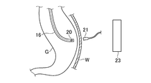
- FIG. 2 is a schematic diagram showing a method of using the endoscope tip position specifying system 10 according to the present embodiment.
- FIG. 2 shows a state in which the insertion portion 16 of the electronic scope main body 13 is inserted into the stomach G, and the operator operates the operation portion 17 to place the distal end of the insertion portion 16 close to the fistula formation position. It is.
- the practitioner picks the second coil 21 and moves it along the abdominal wall W of the patient, and while looking at the monitor 24, the position of the second coil 21 is provided at the distal end of the insertion portion 16.
- Approach 20 At this time, the patient and the magnetic field generator 23 are arranged so that the first and second coils 20 and 21 are located in the magnetic field generated by the magnetic field generator 23 during the treatment.
- FIG. 3 shows an example of a graphic image displayed on the screen S of the monitor 24 when the operation of FIG. 2 is performed.
- the mark 20 ⁇ / b> P indicates the position of the first coil 20
- the mark 21 ⁇ / b> P indicates the position of the second coil 21.
- the state of FIG. 3A shows a state in which the position of the second coil 21 outside the body (mark 21P) is still far from the position of the first coil 20 inside the body (mark 20P). The practitioner moves the second coil 21 while observing the screen S to bring the mark 21P closer to the mark 20P.
- the second coil 21 (mark 21P) is moved in the direction of arrow A along the abdominal wall W.
- FIG. 3 (b) shows a state in which the second coil 21 is moved and the position of the mark 21P is closest to the mark 20P.
- the practitioner moves the second coil 21 back and forth and right and left along the abdominal wall W, and if the position of the mark 21P does not approach the mark 20P any more, the same position on the abdominal wall W becomes a position for opening a fistula.
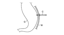
- the practitioner punctures the stomach G from the same position as shown in FIG. 4, attaches the catheter C, and constructs a artificial gastrostomy in the patient's stomach G.
- the positional relationship between the distal end position of the endoscope (first coil) and the hand-held second coil of the practitioner applied to the abdominal wall can be recognized visually and easily.
- the position of the mirror tip can be easily identified from outside the body.
- the present invention can also be applied to an endoscope using an image guide fiber or the like.
- the first coil is disposed at the distal end of the insertion portion of the electronic scope (the distal side of the bending portion).
- the first coil is provided at the distal end of a probe-like instrument, It is good also as a structure with which it mounts
- the first coil provided in the insertion unit is directly connected to the signal processing unit without going through the connector unit, and the endoscope tip position specifying system can be configured independently of the endoscope.
- first coil and the second coil may be connected to the signal processing unit by wireless communication.
- a magnetic field is generated by the third coil of the external device disposed outside the patient's body, and the same magnetic field is detected by the first coil disposed in the patient's body and the second coil operated by hand.
- it is good also as a structure which generates a magnetic field with a 1st, 2nd coil, and detects a magnetic field with a 3rd coil.
- the three-dimensional position measuring device is used.
- the present invention only needs to specify the relative positional relationship between the first and second coils. Therefore, it is sufficient that the relative positional relationship between the first and second coils can be shown without displaying the positions of the first and second coils three-dimensionally. For example, the position of the second coil around the first coil. The structure which shows the information corresponding to the top view which shows these, or both distance may be sufficient.
- the first coil is disposed only at the distal end of the insertion portion. However, a configuration may be adopted in which a plurality of first coils are disposed along the longitudinal direction of the insertion portion and the shape of the insertion portion can be grasped.
Landscapes
- Physics & Mathematics (AREA)
- Health & Medical Sciences (AREA)
- Life Sciences & Earth Sciences (AREA)
- Surgery (AREA)
- Optics & Photonics (AREA)
- Biomedical Technology (AREA)
- Medical Informatics (AREA)
- Nuclear Medicine, Radiotherapy & Molecular Imaging (AREA)
- Pathology (AREA)
- Radiology & Medical Imaging (AREA)
- Astronomy & Astrophysics (AREA)
- Engineering & Computer Science (AREA)
- General Physics & Mathematics (AREA)
- Biophysics (AREA)
- Molecular Biology (AREA)
- Heart & Thoracic Surgery (AREA)
- Animal Behavior & Ethology (AREA)
- General Health & Medical Sciences (AREA)
- Public Health (AREA)
- Veterinary Medicine (AREA)
- Endoscopes (AREA)
- Instruments For Viewing The Inside Of Hollow Bodies (AREA)
Abstract
内視鏡挿入部先端に配置される第1コイルと、手持ち操作可能な第2コイルと、第3コイルを備え、第1コイルおよび第2コイルの間の位置関係を検出する位置検出手段と、位置関係を表示する位置関係表示手段とを備える内視鏡先端位置特定システム。
Description
本発明は、上部消化管用の内視鏡装置を用いた位置合わせ装置に関する。
飲食物や薬などの口から経口摂取が困難な患者に対し、腹部の外側から胃に人口的な瘻孔を形成し、形成された瘻孔にカテーテルを装着して、カテーテルを通して飲食物や薬を直接胃内部に投入可能にする経皮内視鏡的胃瘻造設術(PEG)が知られている。胃瘻の造設では、胃の内部に挿入した内視鏡で胃瘻形成位置を確認するとともに内視鏡先端から胃瘻形成位置に向けて強い光を照射し、皮膚表面まで透過した光の位置から外部からの胃瘻形成位置を特定して同位置に瘻孔を形成する。また、患者の体に空けた孔を通して体腔内に内視鏡を挿入し、マニピュレータを用いて内視鏡や処置具を操作し施術を行う装置において、マニピュレータによる内視鏡や処置具の制御のため、体に開けられた挿入孔の位置を装置に教示する方法が知られている(特許文献1)。
本発明は、より簡便に体内の内視鏡先端位置を体外から特定することを課題としている。
本発明の内視鏡先端位置特定システムは、内視鏡挿入部先端に配置される第1コイルと、手持ち操作可能な第2コイルと、第3コイルを備え、第1コイルおよび第2コイルの間の位置関係を検出する位置検出手段と、位置関係を表示する位置関係表示手段とを備えたことを特徴としている。
位置検出手段は、第1および第2コイルの3次元的な位置情報を検出する。位置関係表示手段は、例えば第1および第2コイルの3次元的な位置関係を表示する。
本発明の内視鏡装置は、上記の内視鏡先端位置特定システムが搭載されたことを特徴としている。
本発明によれば、より簡便に体内の内視鏡先端位置を体外から特定することができる。
以下、本発明の実施の形態を、図面を参照して説明する。図1は、本発明の一実施形態である内視鏡先端位置特定システムの構成を示すブロック図である。
本実施形態の内視鏡先端位置特定システム10は、電子内視鏡装置11とこれに接続される3次元位置測定装置12とから構成される。電子内視鏡装置11は上部消化器内視鏡であり、電子スコープ本体13と、電子スコープ本体13からの画像信号を処理するプロセッサ装置14と、プロセッサ装置14で処理された画像を表示するモニタ装置15とを備える。なお、本実施形態のプロセッサ装置14は、内視鏡観察の照明に用いる光源(不図示)を備える。
電子スコープ本体13は、体内に挿入される挿入部16と、挿入部16の基端側が接続される操作部17と、ユニバーサルコードを介して操作部17を電気的、光学的にプロセッサ装置14へと接続するコネクタ部18を備える。挿入部16は可撓管からなり、その先端には撮像素子19が配置される。挿入部16の先端からは、ライトガイド(不図示)を介してプロセッサ装置14の光源からの光が伝送され、照明光として照射される。撮像素子19で撮影された画像は、プロセッサ装置14で所定の信号処理が施された後、モニタ装置15に出力され内視鏡画像として表示される。
また挿入部16の先端部近傍には所定の長さに亘り、操作部17に設けられた操作レバーあるいは操作ノブ(不図示)の操作により湾曲可能な湾曲部が設けられる。施術者はモニタ装置15の内視鏡画像を見ながら操作部17および操作レバーを操作して挿入部16の先端を胃の中の様々な位置に配置するとともに様々な方向に向けることができる。
本実施形態の3次元位置測定装置12は磁場式の位置測定装置であり、挿入部16の先端(湾曲部よりも先のセグメント)には、3次元位置測定装置12の一部をなす第1コイル20が配置される。3次元位置測定装置12は、挿入部16の先端に設けられる第1コイル20の他、患者の体外に配置され、施術者が手で持って操作する第2コイル21と、第1、第2コイル20、21からの信号を受信する信号処理部22と、信号処理部22に接続され、同装置からの制御信号に基づき、第3コイル(不図示)により磁場を発生させる磁場発生装置(外部装置)23と、第1、第2コイル20、21の3次元的な位置をグラフィック表示するモニタ24とを備える。
第1、第2コイル20、21は、例えば鉄心周りにコイルを巻いたものであり、第1、第2コイル20、21の3次元的な位置は、磁場発生装置23で生成される磁場の歪みと、同磁場内に配置される第1、第2コイル20、21の信号に基づき信号処理部22において計算される。信号処理部22は、この計算結果に基づき所定の視点から見た3次元画像を生成し、モニタ24に出力する。なお、第1コイル20からの信号は、例えばコネクタ部18に設けられた中継回路25に着脱自在に接続される信号線を介して信号処理部22に送られ、第2コイル21は、信号線を介して直接信号処理部22に着脱自在に接続される。
図2は、本実施形態の内視鏡先端位置特定システム10の使用方法を示す模式図である。図2には、電子スコープ本体13の挿入部16が胃G内に挿入され、施術者が操作部17を操作して、挿入部16の先端を瘻孔形成位置に近接させて配置した状態が示される。同状態において、施術者は第2コイル21を摘み患者の腹壁Wに沿ってこれを移動し、モニタ24を見ながら、第2コイル21の位置を挿入部16の先端に設けられた第1コイル20に近づける。なお、このとき患者と磁場発生装置23は、同処置中に第1、第2コイル20、21が磁場発生装置23で生成される磁場内に位置するように配置される。
図3は、図2の操作を行う際にモニタ24の画面Sに表示されるグラフィック画像の一例を示す。図3においてマーク20Pは第1コイル20の位置を示し、マーク21Pは第2コイル21の位置を示す。図3(a)の状態は、体外の第2コイル21の位置(マーク21P)が体内の第1コイル20の位置(マーク20P)からまだ遠い状態を示す。施術者はこの画面Sを観察しながら第2コイル21を動かしマーク21Pの位置をマーク20Pに近づける。図3(a)では、腹壁Wに沿って矢印Aの方向に第2コイル21(マーク21P)が移動される。
図3(b)には、第2コイル21を動かしマーク21Pの位置をマーク20Pに最も近づけた状態が示される。施術者はこの近傍で第2コイル21を腹壁Wに沿って前後左右に移動させ、マーク21Pの位置がこれ以上マーク20Pに近づけなければ、腹壁W上の同位置が瘻孔を空ける位置となる。位置が特定されると施術者は、図4に示されるように同位置から胃Gに孔を空け、カテーテルCを装着し患者の胃Gに人口的な胃瘻を造設する。
以上のように、本実施形態によれば、内視鏡先端位置(第1コイル)と腹壁に当てた施術者の手持ち第2コイルの位置関係を視覚的に簡便に認識でき、体内の内視鏡先端位置を体外から簡便に特定することができる
本実施形態では電子内視鏡を例に説明を行なったが、本発明はイメージガイドファイバなどを用いた内視鏡にも適用できる。また本実施形態では電子スコープの挿入部先端(湾曲部よりも先端側)に第1コイルを配置したが、例えばプローブ状の器具の先端に第1コイルを設け、同器具を鉗子口から挿入部に装着する構成としてもよい。その場合、挿入部に設けられる第1コイルは、コネクタ部を介することなく信号処理部に直接接続され、内視鏡先端位置特定システムは内視鏡とは独立した構成とすることができる。なお、第1コイル、第2コイルの一方、または第1コイル、第2コイルの両方を無線通信で信号処理部に接続する構成とすることもできる。また、本実施形態では、患者の体外に配置される外部装置の第3コイルで磁場を発生し、患者の体内に配置される第1コイル、手持ち操作される第2コイルで同磁場を検出したが、第1、第2コイルで磁場を発生し、第3コイルで磁場を検出する構成としてもよい。
また本実施形態では3次元位置測定装置を用いたが、本発明は第1、第2コイルの相対的な位置関係が特定できればよい。したがって、第1、第2コイルの位置を3次元的に画像表示しなくとも、第1、第2コイルの相対的な位置関係が示せればよく、例えば第1コイルを中心に第2コイルの位置を示す平面図や、両者の距離に対応する情報を示す構成であってもよい。更に、本実施形態では、挿入部の先端にのみ第1コイルを配置したが、挿入部長手方向にそって複数の第1コイルを配置し、挿入部の形状も把握できる構成としてもよい。
10 内視鏡先端位置特定システム
11 電子内視鏡装置
12 3次元位置測定装置
13 電子スコープ本体
16 挿入部
19 撮像素子
20 第1コイル
21 第2コイル
22 信号処理部
23 磁場発生装置(外部装置)
24 モニタ
11 電子内視鏡装置
12 3次元位置測定装置
13 電子スコープ本体
16 挿入部
19 撮像素子
20 第1コイル
21 第2コイル
22 信号処理部
23 磁場発生装置(外部装置)
24 モニタ
Claims (5)
- 内視鏡挿入部先端に配置される第1コイルと、
手持ち操作可能な第2コイルと、
第3コイルを備え、前記第1コイルおよび前記第2コイルの間の位置関係を検出する位置検出手段と、
前記位置関係を表示する位置関係表示手段と
を備えることを特徴とする内視鏡先端位置特定システム。 - 前記位置検出手段が、前記第1および第2コイルの3次元的な位置情報を検出することを特徴とする請求項1に記載の内視鏡先端位置特定システム。
- 前記位置関係表示手段が、前記第1および第2コイルの3次元的な位置関係を表示することを特徴とする請求項1~2の何れか一項に記載の内視鏡先端位置特定システム。
- 前記第1コイルが内視鏡挿入部に装着可能なプローブ状の器具の先端に設けられることを特徴とする請求項1~3の何れか一項に記載の内視鏡先端位置特定システム。
- 請求項1~4の何れか一項に記載の内視鏡先端位置特定システムが搭載されることを特徴とする内視鏡装置。
Priority Applications (1)
| Application Number | Priority Date | Filing Date | Title |
|---|---|---|---|
| CN201780000887.6A CN107438388A (zh) | 2016-03-25 | 2017-02-09 | 内窥镜顶端位置确定系统 |
Applications Claiming Priority (2)
| Application Number | Priority Date | Filing Date | Title |
|---|---|---|---|
| JP2016-061948 | 2016-03-25 | ||
| JP2016061948A JP2017169994A (ja) | 2016-03-25 | 2016-03-25 | 内視鏡先端位置特定システム |
Publications (1)
| Publication Number | Publication Date |
|---|---|
| WO2017163653A1 true WO2017163653A1 (ja) | 2017-09-28 |
Family
ID=59901142
Family Applications (1)
| Application Number | Title | Priority Date | Filing Date |
|---|---|---|---|
| PCT/JP2017/004829 Ceased WO2017163653A1 (ja) | 2016-03-25 | 2017-02-09 | 内視鏡先端位置特定システム |
Country Status (3)
| Country | Link |
|---|---|
| JP (1) | JP2017169994A (ja) |
| CN (1) | CN107438388A (ja) |
| WO (1) | WO2017163653A1 (ja) |
Citations (4)
| Publication number | Priority date | Publication date | Assignee | Title |
|---|---|---|---|---|
| JP2000126302A (ja) * | 1998-08-17 | 2000-05-09 | Yutaka Suzuki | 胃瘻造設法ならびにこの方法で用いられる汚染防止用カバ―および胃瘻造設用カテ―テル・キット |
| JP2000175861A (ja) * | 1998-12-17 | 2000-06-27 | Olympus Optical Co Ltd | 内視鏡形状検出装置 |
| WO2006112136A1 (ja) * | 2005-03-31 | 2006-10-26 | Olympus Medical Systems Corp. | 手術支援装置及び処置支援装置 |
| WO2014176236A1 (en) * | 2013-04-22 | 2014-10-30 | University Of Maryland, Baltimore | Coaptation ultrasound devices and methods of use |
Family Cites Families (4)
| Publication number | Priority date | Publication date | Assignee | Title |
|---|---|---|---|---|
| JP3571675B2 (ja) * | 1998-03-18 | 2004-09-29 | オリンパス株式会社 | コイル位置測定装置およびコイル位置測定方法 |
| JP2000081303A (ja) * | 1998-09-04 | 2000-03-21 | Olympus Optical Co Ltd | 位置検出装置 |
| JP3720727B2 (ja) * | 2001-05-07 | 2005-11-30 | オリンパス株式会社 | 内視鏡形状検出装置 |
| JP5877287B1 (ja) * | 2014-07-29 | 2016-03-02 | オリンパス株式会社 | 内視鏡挿入形状観測プローブ |
-
2016
- 2016-03-25 JP JP2016061948A patent/JP2017169994A/ja active Pending
-
2017
- 2017-02-09 CN CN201780000887.6A patent/CN107438388A/zh active Pending
- 2017-02-09 WO PCT/JP2017/004829 patent/WO2017163653A1/ja not_active Ceased
Patent Citations (4)
| Publication number | Priority date | Publication date | Assignee | Title |
|---|---|---|---|---|
| JP2000126302A (ja) * | 1998-08-17 | 2000-05-09 | Yutaka Suzuki | 胃瘻造設法ならびにこの方法で用いられる汚染防止用カバ―および胃瘻造設用カテ―テル・キット |
| JP2000175861A (ja) * | 1998-12-17 | 2000-06-27 | Olympus Optical Co Ltd | 内視鏡形状検出装置 |
| WO2006112136A1 (ja) * | 2005-03-31 | 2006-10-26 | Olympus Medical Systems Corp. | 手術支援装置及び処置支援装置 |
| WO2014176236A1 (en) * | 2013-04-22 | 2014-10-30 | University Of Maryland, Baltimore | Coaptation ultrasound devices and methods of use |
Also Published As
| Publication number | Publication date |
|---|---|
| CN107438388A (zh) | 2017-12-05 |
| JP2017169994A (ja) | 2017-09-28 |
Similar Documents
| Publication | Publication Date | Title |
|---|---|---|
| CN100464687C (zh) | 双气囊式内窥镜系统 | |
| EP1864624B1 (en) | Surgery assisting apparatus | |
| CN100496375C (zh) | 内窥镜和内窥镜系统 | |
| US10925576B2 (en) | Apparatus, system and methods for proper transesophageal echocardiography probe positioning by using camera for ultrasound imaging | |
| JP7367976B2 (ja) | 手術器具の自動検出のための検出システムおよび方法 | |
| WO2000060996A1 (en) | Method and apparatus for magnetically controlling endoscopes in body lumens and cavities | |
| CN113194818B (zh) | 用于体腔治疗的装置和方法 | |
| US20190142523A1 (en) | Endoscope-like devices comprising sensors that provide positional information | |
| JP6616838B2 (ja) | 内視鏡形状把握システム | |
| US20230148849A1 (en) | Medical system and cannulation method | |
| JP2017169994A (ja) | 内視鏡先端位置特定システム | |
| JP2008018257A (ja) | 医療装置 | |
| JP6400221B2 (ja) | 内視鏡形状把握システム | |
| TWI762812B (zh) | 內視鏡與內視鏡設備及內視鏡的定位方法 | |
| CN107427195B (zh) | 内窥镜形状掌握系统 | |
| JP2005334472A (ja) | 医療システム | |
| JP4789490B2 (ja) | 内視鏡装置 | |
| JP2017213316A (ja) | コイルユニット、医療器具 | |
| JP2005334473A (ja) | 医療システム | |
| JP2001145598A (ja) | 内視鏡の体内挿入部の彎曲検知方法及び装置 | |
| JP2011235114A (ja) | 画像信号処理装置 |
Legal Events
| Date | Code | Title | Description |
|---|---|---|---|
| NENP | Non-entry into the national phase |
Ref country code: DE |
|
| 121 | Ep: the epo has been informed by wipo that ep was designated in this application |
Ref document number: 17769700 Country of ref document: EP Kind code of ref document: A1 |
|
| 122 | Ep: pct application non-entry in european phase |
Ref document number: 17769700 Country of ref document: EP Kind code of ref document: A1 |