WO2017163646A1 - パッケージ型圧縮機 - Google Patents
パッケージ型圧縮機 Download PDFInfo
- Publication number
- WO2017163646A1 WO2017163646A1 PCT/JP2017/004705 JP2017004705W WO2017163646A1 WO 2017163646 A1 WO2017163646 A1 WO 2017163646A1 JP 2017004705 W JP2017004705 W JP 2017004705W WO 2017163646 A1 WO2017163646 A1 WO 2017163646A1
- Authority
- WO
- WIPO (PCT)
- Prior art keywords
- package
- pair
- suction port
- wall
- suction
- Prior art date
- Legal status (The legal status is an assumption and is not a legal conclusion. Google has not performed a legal analysis and makes no representation as to the accuracy of the status listed.)
- Ceased
Links
Images



Classifications
-
- F—MECHANICAL ENGINEERING; LIGHTING; HEATING; WEAPONS; BLASTING
- F04—POSITIVE - DISPLACEMENT MACHINES FOR LIQUIDS; PUMPS FOR LIQUIDS OR ELASTIC FLUIDS
- F04B—POSITIVE-DISPLACEMENT MACHINES FOR LIQUIDS; PUMPS
- F04B39/00—Component parts, details, or accessories, of pumps or pumping systems specially adapted for elastic fluids, not otherwise provided for in, or of interest apart from, groups F04B25/00 - F04B37/00
-
- F—MECHANICAL ENGINEERING; LIGHTING; HEATING; WEAPONS; BLASTING
- F04—POSITIVE - DISPLACEMENT MACHINES FOR LIQUIDS; PUMPS FOR LIQUIDS OR ELASTIC FLUIDS
- F04C—ROTARY-PISTON, OR OSCILLATING-PISTON, POSITIVE-DISPLACEMENT MACHINES FOR LIQUIDS; ROTARY-PISTON, OR OSCILLATING-PISTON, POSITIVE-DISPLACEMENT PUMPS
- F04C29/00—Component parts, details or accessories of pumps or pumping installations, not provided for in groups F04C18/00 - F04C28/00
-
- F—MECHANICAL ENGINEERING; LIGHTING; HEATING; WEAPONS; BLASTING
- F04—POSITIVE - DISPLACEMENT MACHINES FOR LIQUIDS; PUMPS FOR LIQUIDS OR ELASTIC FLUIDS
- F04C—ROTARY-PISTON, OR OSCILLATING-PISTON, POSITIVE-DISPLACEMENT MACHINES FOR LIQUIDS; ROTARY-PISTON, OR OSCILLATING-PISTON, POSITIVE-DISPLACEMENT PUMPS
- F04C29/00—Component parts, details or accessories of pumps or pumping installations, not provided for in groups F04C18/00 - F04C28/00
- F04C29/06—Silencing
Definitions
- the present invention relates to a package type compressor.
- the suction pulsation radiated from the suction filter serves as an excitation source, and the first-order half-wave standing wave is mainly formed between the opposing wall surfaces in the package internal space.
- humming noise low-frequency resonance
- the sounding effect cannot be obtained. It is important not to generate.
- An object of the present invention is to reduce noise such as a booming noise in a package type compressor.
- the suction port is installed downward. This is because a relatively cool fluid existing under the package internal space is sucked from the viewpoint of compression efficiency. Also, if the suction port is installed upward, foreign matter such as dust may be mixed from the suction port, and this is also to prevent this. Therefore, in the conventional package type compressor, no special consideration is given to reducing the noise by changing the direction of the suction port. As a result of various experiments and examinations, the present inventor has found that the direction of the suction port greatly affects noise. The present invention is based on such new knowledge.
- the present invention is arranged between three facing first wall pairs, second wall surface pairs, and third wall surface pairs that define a package internal space, and the first wall surface pair of the package internal space, and a suction port And a compressor body having a suction filter attached thereto, and an axial line of the suction port passes through a virtual first central plane at the center of the first wall surface pair.
- the position of the first center plane becomes the position of the node of the sound pressure in the primary resonance mode generated between the first pair of wall surfaces, and the suction port is directed to the first center plane. Since noise can be radiated toward the node of the sound pressure, resonance excitation can be suppressed and noise can be reduced. In particular, it is effective to be able to reduce the muffled noise that cannot be obtained with a sound-absorbing material with a sound-absorbing material or the like generated during low-speed operation. In addition, by specifically defining the direction of the suction port in this way, noise can be reliably radiated toward the first center plane that becomes a node of sound pressure.
- the compressor body is disposed between the second wall surface pair in the package internal space, and an axis of the suction port passes through a virtual first center surface at the center of the first wall surface pair. .
- the accuracy of resonance suppression can be improved by supporting the first-order resonance modes in the two directions between the first wall pair and the second wall pair.
- the compressor main body is disposed between the third wall surface pair in the package internal space, and the axis of the suction port passes through a virtual first center surface of the center of the first wall surface pair. .
- the accuracy of resonance suppression can be further improved by supporting the three-way primary resonance mode between the first wall pair, the second wall pair, and the third wall pair.
- the extension filter for changing the suction position and the suction direction may be attached to the suction filter, and the suction port may be an opening of the extension pipe.
- a compressor main body to which a suction filter having a suction port is attached, wherein the suction port is located on a virtual first center plane at the center of the first wall pair.
- the excitation of resonance can be reliably suppressed by radiating noise at the position of the sound pressure node in the primary resonance mode generated between the first wall pair.
- the position of the first center plane becomes the position of the node of the sound pressure of the primary resonance mode generated between the first wall pair, and the suction port is directed to the first center plane. Since noise can be emitted toward the node of the sound pressure, excitation of resonance can be suppressed, and noise such as booming noise can be reduced.
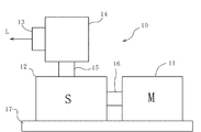
- the typical top view of the package type compressor concerning a 1st embodiment of the present invention.
- the schematic diagram which shows the structure of a compressor main body.
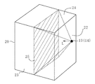
- the typical perspective view which shows the positional relationship of a 1st center plane and a suction inlet.
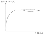
- the graph which compared the attenuation amount of the sound energy by the direction of a suction inlet.
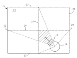
- the typical top view which shows the positional relationship of a 1st center surface and 2nd center surface, and a suction inlet.
- the typical top view in case the suction inlet is on the 1st center plane.
- the typical top view of the package type compressor concerning a 2nd embodiment of the present invention.
- the typical top view of the package type compressor concerning a 3rd embodiment of the present invention.
- FIG. 1 is a schematic plan view of a package compressor 1 according to the first embodiment.
- the compressor main body 10 is accommodated in the package 20, and noise generated from the compressor main body 10 can be shielded by the package 20.
- the package 20 includes a first pair of wall surfaces 22 and 22, a second pair of wall surfaces 23 and 23, and a third pair of wall surfaces 24 and 24 (see FIG. 3) that define a package internal space 21. Therefore, the package internal space 21 of the present embodiment is a rectangular parallelepiped space. However, the package internal space 21 is not limited to a rectangular parallelepiped shape, and may be another shape such as a columnar shape or a spherical shape. In the case of a columnar shape or a spherical shape, three wall pairs are not provided, but in this case, facing wall portions at positions corresponding to the respective wall pairs are treated as wall pairs.
- the compressor body 10 includes a package inner space 21 between the first wall surface pair 22, 22, between the second wall surface pair 23, 23, and between the third wall surface pair 24, 24. Is arranged.
- the compressor body 10 includes a motor unit 11 and a screw unit 12.
- a suction filter 14 having a suction port 13 is attached to the screw part 12 through a pipe 15.
- the screw portion 12 accommodates a pair of male and female screws (not shown).
- a motor (not shown) is accommodated in the motor unit 11, and the motor is mechanically connected to the screw of the screw unit 12 via the rotating shaft 16.
- the screw inside the screw unit 12 is rotationally driven, and air is sucked from the suction port 13 and compressed by the screw unit 12, and the supply destination (not shown) Compressed air is discharged.
- the motor unit 11 and the screw unit 12 are both installed on the mounting base 17 and are fixed in the package 20 so that their positions and orientations are not changed.
- the compressor body 10 is a screw type, but may be a turbo type, a scroll type, a reciprocating type, or the like.
- the inventors of the present application have found that the orientation of the suction port 13 in the package internal space 21 has an influence on the generation of a muffled sound by conducting an investigation with the actual package type compressor 1. Furthermore, the direction of the suction inlet 13 which can suppress generation
- the suction filter 14 is provided so that the axis L of the suction port 13 passes through the first center plane 25. That is, the axis L of the suction port 13 is located in a quadrangular pyramid that connects the suction port 13 and the first center plane 25. However, not only the case where the axis L of the suction port 13 is completely located within the quadrangular pyramid, but also a positional shift equivalent to an error when the suction filter 14 is attached is allowed.
- the vertical axis of the graph is the total noise energy generated in the package internal space 21, and the horizontal axis is the frequency.
- the horizontal axis of the graph indicates a band up to about 200 Hz in order to see the effect on low-frequency resonance called “bump sound”.
- the solid line graph shows the case where the suction port 13 is directed to the first center plane so that the axis L thereof is orthogonal to the first center plane 25 as shown in FIG. 1, and the broken line graph is drawn opposite to FIG.
- the position of the first center plane 25 is the position of the node of the sound pressure in the primary resonance mode generated between the first wall surface pair 22,22. Therefore, by directing the suction port 13 toward the first central plane 25, noise can be emitted toward the node of the sound pressure, so that excitation of resonance can be suppressed and noise can be reduced. In particular, it is effective to be able to reduce the muffled noise that cannot be obtained with a sound-absorbing material with a sound-absorbing material or the like generated during low-speed operation.
- the axis L of the suction port 13 penetrates the first center surface 25 and the second center surface 26. That is, the axis L of the suction port 13 is located within the hatched area in FIG.
- a positional shift equivalent to an error when the suction filter 14 is attached is allowed.
- the axis L of the suction port 13 should pass through the first center plane 25, the second center plane 26, and the third center plane 27.
- a positional shift equivalent to an error when the suction filter 14 is attached is allowed.
- the resonance suppression is suppressed by corresponding to the first-order resonance modes in the three directions between the first wall pair 22, 22, the second wall pair 23, 23, and the third wall pair 24, 24.
- the accuracy can be further improved.
- the suction port 13 may be located on the first center plane 25. By emitting noise at the position of the first resonance mode sound pressure node generated between the first wall pair 22 and 22, resonance excitation can be reliably suppressed. Moreover, the suction inlet 13 may be located on the 2nd center surface 26 and the 3rd center surface 27, and may further improve the precision of suppression of resonance.
- FIG. 7 is a schematic plan view of the package compressor 1 according to the second embodiment.
- the configuration other than the addition of the extension pipe 18 from the first embodiment of FIG. 1 is substantially the same as that of the first embodiment of FIG. Therefore, the description of the same parts as those shown in FIG. 1 is omitted.
- an extension pipe 18 for changing the suction position and the suction direction is attached to the suction filter 14.
- the extension pipe 18 of this embodiment has openings 18a and 18b at both ends.
- the opening 18a at one end and the opening 18b at the other end are opened in different directions. Accordingly, when air flows from the opening 18a at one end to the opening 18b at the other end, the flow direction is changed.
- the opening 18 a at one end is approximately the same size as the suction port 13 and is attached to the suction port 13 without a gap.
- the opening 18 b at the other end serves as a suction port 13 for sucking air, and its axis L passes through the first center plane 25.
- the shape of the extension pipe 18 is not specifically limited, Other shapes may be sufficient if a suction position and a suction direction can be changed.
- FIG. 8 is a schematic plan view of the package compressor 1 according to the third embodiment.
- the configuration other than the addition of the partition wall 28 from the first embodiment of FIG. 1 is substantially the same as that of the first embodiment of FIG. Therefore, the description of the same parts as those shown in FIG. 1 is omitted.
- the partition wall 28 is provided between the first wall surface pair 22, 22. For this reason, in the package internal space 21, low-order resonance in which a first-order half-wave standing wave is mainly formed between the first wall surface 22 and the partition wall 28 is excited. That is, the provision of the partition wall 28 changes the position of the primary resonance mode sound pressure node, and the primary resonance mode sound pressure node is located at the center between the first wall surface 22 and the partition wall 28. To do. Therefore, in the present embodiment, the first wall surface pair 22 and 28 are formed by the first wall surface 22 and the partition wall 28, and the position of the first center surface 25 is also changed from the first embodiment, and the first wall surface 22 and the partition wall 28 are partitioned. Located in the center with the wall 28.
- the axis L of the suction port 13 of the present embodiment passes through the first center plane 25 whose position has been changed by providing the partition wall 28.
- the first central plane 25 can be substantially located at the position of the node of the sound pressure in the primary resonance mode, and the resonance can be reliably suppressed.
Landscapes
- Engineering & Computer Science (AREA)
- Mechanical Engineering (AREA)
- General Engineering & Computer Science (AREA)
- Compressor (AREA)
- Applications Or Details Of Rotary Compressors (AREA)
Abstract
パッケージ型圧縮機1は、パッケージ内部空間21を画定する対面する3対の第1壁面対22,22、第2壁面対23,23、及び第3壁面対24,24と、パッケージ内部空間21の第1壁面対22,22の間に配置され、吸込口13を有する吸込フィルタ14が取り付けられた圧縮機本体10とを備える。吸込口13の軸線Lが第1壁面対22,22の中心の仮想の第1中心面25を貫通している。
Description
本発明は、パッケージ型圧縮機に関する。
パッケージ型圧縮機では、吸込フィルタから放射される吸込脈動が加振源となって、パッケージ内部空間で対向する壁面間に主に1次で半波長の定在波が形成される低次共鳴が励起される。特に200Hz程度以下の低周波数帯域でこもり音と呼ばれる低周波共鳴が発生すると、一般に防音対策で使用されるグラスウールや発泡ウレタンなどの吸音材を内張りしても防音効果を得られないため、こもり音は発生させないことが重要である。
本発明は、パッケージ型圧縮機において、こもり音等の騒音を低減することを課題とする。
従来の多くのパッケージ型圧縮機では、吸込口は下向きに設置されている。圧縮効率の観点からパッケージ内部空間の下方に存在する相対的に冷たい流体を吸い込むためである。また、吸込口を上向きに設置すると吸込口からゴミ等の異物が混入する場合もあり、これを防止するためでもある。従って、従来のパッケージ型圧縮機では、吸込口の向きを変更して騒音を低減することについて特段の考慮がなされていない。本発明者は、種々の実験や検討の結果、吸込口の向きが騒音に大きな影響を与えることを見出した。本発明はかかる新たな知見に基づくものである。
本発明は、パッケージ内部空間を画定する対面する3対の第1壁面対、第2壁面対、及び第3壁面対と、前記パッケージ内部空間の前記第1壁面対の間に配置され、吸込口を有する吸込フィルタが取り付けられた圧縮機本体とを備え、前記吸込口の軸線が前記第1壁面対の中心の仮想の第1中心面を貫通しているパッケージ型圧縮機を提供する。
この構成によれば、パッケージ型圧縮機において、第1中心面の位置が第1壁面対の間に生じる1次共鳴モードの音圧の節の位置となり、吸込口を第1中心面に向けることで、その音圧の節に向けて騒音を放射できるため、共鳴の励起を抑制でき、騒音を低減できる。特に低回転数運転時に発生する吸音材等では防音効果が得られないこもり音を低減できることは有効である。また、このように吸込口の方向を具体的に規定することで確実に音圧の節となる第1中心面に向けて騒音を放射できる。
前記圧縮機本体は、前記パッケージ内部空間の前記第2壁面対の間に配置され、前記吸込口の軸線が前記第1壁面対の中心の仮想の第1中心面を貫通していることが好ましい。
第1壁面対間及び第2壁面対間の2方向の1次共鳴モードに対応することで、共鳴の抑制の確度を向上できる。
前記圧縮機本体は、前記パッケージ内部空間の前記第3壁面対の間に配置され、前記吸込口の軸線が前記第1壁面対の中心の仮想の第1中心面を貫通していることが好ましい。
第1壁面対間、第2壁面対間、及び第3壁面対間の3方向の1次共鳴モードに対応することで、共鳴の抑制の確度をさらに向上できる。
前記吸込フィルタには吸込位置及び吸込方向を変更する延長パイプが取り付けられ、前記吸込口は前記延長パイプの開口であってもよい。
延長パイプを取り付けることで、吸込口への異物の混入を防止できる。また、設置スペースの制約などの理由により吸込フィルタの向きが規定され吸込方向を自由にできない場合にも、延長パイプにより吸込口の向きを自由に変更できる。
本発明の第2の態様は、パッケージ内部空間を画定する対面する3対の第1壁面対、第2壁面対、及び第3壁面対と、前記パッケージ内部空間の前記第1壁面対の間に配置され、吸込口を有する吸込フィルタが取り付けられた圧縮機本体とを備え、前記吸込口は、前記第1壁面対の中心の仮想の第1中心面上に位置する、パッケージ型圧縮機を提供する。
第1壁面対間に生じる1次共鳴モードの音圧の節の位置で騒音を放射することで、確実に共鳴の励起を抑制できる。
本発明によれば、パッケージ型圧縮機において、第1中心面の位置が第1壁面対の間に生じる1次共鳴モードの音圧の節の位置となり、吸込口を第1中心面に向けることでその音圧の節に向けて騒音を放射できるため、共鳴の励起を抑制でき、こもり音等の騒音を低減できる。
以下、添付図面を参照して本発明の実施形態を説明する。
(第1実施形態)
図1は、第1実施形態に係るパッケージ型圧縮機1の模式的な平面図である。パッケージ型圧縮機1では、圧縮機本体10がパッケージ20内に収容されており、パッケージ20により圧縮機本体10から発生する騒音を遮蔽できる。
図1は、第1実施形態に係るパッケージ型圧縮機1の模式的な平面図である。パッケージ型圧縮機1では、圧縮機本体10がパッケージ20内に収容されており、パッケージ20により圧縮機本体10から発生する騒音を遮蔽できる。
パッケージ20は、パッケージ内部空間21を画定する対向する第1壁面対22,22、第2壁面対23,23、及び第3壁面対24,24(図3参照)を備える。従って、本実施形態のパッケージ内部空間21は、直方体状の空間である。ただし、パッケージ内部空間21は、直方体状に限定されず、円柱状や球状等の他の形状であってもよい。円柱状や球状の場合、3対の壁面対が設けられないが、その場合は各壁面対に対応する位置にある対面する壁面部を壁面対として扱う。
図2及び図3を参照して圧縮機本体10は、パッケージ内部空間21の第1壁面対22,22の間、第2壁面対23,23の間、及び第3壁面対24,24の間に配置されている。圧縮機本体10は、モータ部11とスクリュ部12とを備える。スクリュ部12には、吸込口13を有する吸込フィルタ14が配管15を通じて取り付けられている。スクリュ部12には、図示しない雌雄一対のスクリュが収容されている。モータ部11には、図示しないモータが収容されており、該モータはスクリュ部12のスクリュと回転軸16を介して機械的に接続されている。
モータ部11に電力が供給され内部のモータが駆動されると、合わせてスクリュ部12の内部のスクリュが回転駆動され、吸込口13より空気を吸い込んでスクリュ部12で圧縮し、図示しない供給先に圧縮空気を吐出する。モータ部11及びスクリュ部12は、共に取付台17に設置され、その位置や向きが変更されないようにパッケージ20内で固定される。本実施形態では、圧縮機本体10は、スクリュ式であるが、ターボ式、スクロール式、及びレシプロ式等であってもよい。
本願発明者らはパッケージ型圧縮機1の実機での調査により、パッケージ内部空間21における吸込口13の向きがこもり音の発生に影響を与えることを見出した。さらに、数値解析による数値実験により、こもり音の発生を抑制できる吸込口13の向きを見出した。
図1及び図3を参照して、吸込フィルタ14は、吸込口13の軸線Lが第1中心面25を貫通するように設けられている。即ち、吸込口13と第1中心面25を結ぶ四角錐内に吸込口13の軸線Lが位置している。ただし、該四角錐内に吸込口13の軸線Lが完全に位置する場合だけでなく、吸込フィルタ14の取り付け時の誤差程度の位置ずれは許容される。
図4を参照して、吸込口13の向きによる騒音のエネルギーを比較する。グラフの縦軸はパッケージ内部空間21に生じた騒音エネルギーの総和であり、横軸は周波数である。特に、グラフに数値は付していないが、こもり音と呼ばれる低周波共鳴に対する効果を見るため、グラフの横軸は200Hz程度までの帯域を示している。実線のグラフは図1に示すように吸込口13をその軸線Lが第1中心面25と直交するように第1中心面に向けた場合を示し、破線のグラフは図1とは反対に吸込口13をその軸線Lが第1中心面25と直交するように第1中心面から離れる方向に向けた場合を示す。グラフを確認すると、吸込口13を第1中心面25に向けた場合(実線)の方が吸込口を第1中心面25から離れる方向に向けた場合(破線)よりも騒音エネルギーが減少している。従って、吸込口13を第1中心面25に向けることは騒音防止の観点から有効である。
このように、パッケージ型圧縮機1において、第1中心面25の位置が第1壁面対22,22の間に生じる1次共鳴モードの音圧の節の位置となっている。そのため、吸込口13を第1中心面25に向けることで、その音圧の節に向けて騒音を放射できるため、共鳴の励起を抑制でき、騒音を低減できる。特に低回転数運転時に発生する吸音材等では防音効果が得られないこもり音を低減できることは有効である。
図5を参照して、好ましくは、吸込口13の軸線Lは、第1中心面25及び第2中心面26を貫通している方がよい。即ち、吸込口13の軸線Lは、図5の斜線部の範囲内に位置する。ただし、上述と同様に、吸込フィルタ14の取り付け時の誤差程度の位置ずれは許容される。このようにして、第1壁面対22,22間及び第2壁面対23,23間の2方向の1次共鳴モードに対応することで、共鳴の抑制の確度を向上できる。
さらに好ましくは、吸込口13の軸線Lは、第1中心面25、第2中心面26、及び第3中心面27を貫通している方がよい。ただし、上述と同様に、吸込フィルタ14の取り付け時の誤差程度の位置ずれは許容される。このようにして、第1壁面対22,22間、第2壁面対23,23間、及び第3壁面対24,24間の3方向の1次共鳴モードに対応することで、共鳴の抑制の確度をさらに向上できる。
図6を参照して、吸込口13は、第1中心面25上に位置してもよい。第1壁面対22,22間に生じる1次共鳴モードの音圧の節の位置で騒音を放射することで、確実に共鳴の励起を抑制できる。また、吸込口13は、第2中心面26及び第3中心面27上に位置し、共鳴の抑制の確度をさらに向上してもよい。
(第2実施形態)
図7は、第2実施形態に係るパッケージ型圧縮機1の模式的な平面図である。本実施形態では、図1の第1実施形態から延長パイプ18が追加されたことに関する以外の構成は図1の第1実施形態と実質的に同様である。従って、図1に示した構成と同様の部分については説明を省略する。
図7は、第2実施形態に係るパッケージ型圧縮機1の模式的な平面図である。本実施形態では、図1の第1実施形態から延長パイプ18が追加されたことに関する以外の構成は図1の第1実施形態と実質的に同様である。従って、図1に示した構成と同様の部分については説明を省略する。
本実施形態では、吸込フィルタ14に対し、吸込位置や吸込方向を変更するための延長パイプ18が取り付けられている。本実施形態の延長パイプ18は、両端に開口18a,18bを有する。一端の開口18aと他端の開口18bは異なる方向に開口している。従って、一端の開口18aから他端の開口18bまで空気が流動する際にその流動方向が変更される。一端の開口18aは、吸込口13と概略同じ大きさであり、吸込口13に対して隙間なく取り付けられる。他端の開口18bは、空気を吸気する吸込口13となり、その軸線Lは、第1中心面25を貫通している。さらに言えば、他端の開口18bである吸込口13の軸線Lは、第1中心面25だけでなく、第2中心面26及び第3中心面27も貫通している方が好ましい。また、延長パイプ18の形状は特に限定されず、吸込位置や吸込方向を変更できるものであれば他の形状であってもよい。
延長パイプ18を取り付けることで、吸込口13への異物の混入を防止できる。また、設置スペースの制約などの理由により吸込フィルタ14の向きが規定され吸込方向を自由にできない場合にも、延長パイプ18により吸込口13の向きを自由に変更できる。
(第3実施形態)
図8は、第3実施形態に係るパッケージ型圧縮機1の模式的な平面図である。本実施形態では、図1の第1実施形態から仕切壁28が追加されたことに関する以外の構成は図1の第1実施形態と実質的に同様である。従って、図1に示した構成と同様の部分については説明を省略する。
図8は、第3実施形態に係るパッケージ型圧縮機1の模式的な平面図である。本実施形態では、図1の第1実施形態から仕切壁28が追加されたことに関する以外の構成は図1の第1実施形態と実質的に同様である。従って、図1に示した構成と同様の部分については説明を省略する。
本実施形態では、第1壁面対22,22の間に仕切壁28が設けられている。そのため、パッケージ内部空間21で第1壁面22と仕切壁28との間で主に1次で半波長の定在波が形成される低次共鳴が励起される。即ち、仕切壁28が設けられたことにより、1次共鳴モードの音圧の節の位置が変化し、第1壁面22と仕切壁28との中心に1次共鳴モードの音圧の節が位置する。従って、本実施形態では、第1壁面22と仕切壁28とで第1壁面対22,28が形成され、第1中心面25の位置も第1実施形態から変化して第1壁面22と仕切壁28との中心に位置する。
本実施形態の吸込口13の軸線Lは、仕切壁28を設けたことにより位置が変更された第1中心面25を貫通している。このように仕切壁28が存在する場合、これを考慮することで第1中心面25を実質的に生じる1次共鳴モードの音圧の節の位置にでき、確実に共鳴を抑制できる。
以上より、本発明の具体的な実施形態やその変形例について説明したが、本発明は上記形態に限定されるものではなく、この発明の範囲内で種々変更して実施することができる。例えば、個々の実施形態の内容を適宜組み合わせたものを、この発明の一実施形態としてもよい。また、上記の個々の実施形態では、圧縮対象は空気を例に説明したが、空気以外の流体であってもよく、その対象は特に限定されない。
1 パッケージ型圧縮機
10 圧縮機本体
11 モータ部
12 スクリュ部
13 吸込口
14 吸込フィルタ
15 配管
16 回転軸
17 取付台
18 延長パイプ
18a,18b 開口
20 パッケージ
21 パッケージ内部空間
22 第1壁面(第1壁面対)
23 第2壁面(第2壁面対)
24 第3壁面(第3壁面対)
25 第1中心面
26 第2中心面
27 第3中心面
28 仕切壁(第1壁面対)
10 圧縮機本体
11 モータ部
12 スクリュ部
13 吸込口
14 吸込フィルタ
15 配管
16 回転軸
17 取付台
18 延長パイプ
18a,18b 開口
20 パッケージ
21 パッケージ内部空間
22 第1壁面(第1壁面対)
23 第2壁面(第2壁面対)
24 第3壁面(第3壁面対)
25 第1中心面
26 第2中心面
27 第3中心面
28 仕切壁(第1壁面対)
Claims (5)
- パッケージ内部空間を画定する対面する3対の第1壁面対、第2壁面対、及び第3壁面対と、
前記パッケージ内部空間の前記第1壁面対の間に配置され、吸込口を有する吸込フィルタが取り付けられた圧縮機本体と
を備え、
前記吸込口の軸線が前記第1壁面対の中心の仮想の第1中心面を貫通している、パッケージ型圧縮機。 - 前記圧縮機本体は、前記パッケージ内部空間の前記第2壁面対の間に配置され、
前記吸込口の軸線が前記第2壁面対の中心の仮想の第1中心面を貫通している、請求項1に記載のパッケージ型圧縮機。 - 前記圧縮機本体は、前記パッケージ内部空間の前記第3壁面対の間に配置され、
前記吸込口の軸線が前記第3壁面対の中心の仮想の第1中心面を貫通している、請求項1または請求項2に記載のパッケージ型圧縮機。 - 前記吸込フィルタには吸込位置及び吸込方向を変更する延長パイプが取り付けられ、前記吸込口は前記延長パイプの開口である、請求項1または請求項2に記載のパッケージ型圧縮機。
- パッケージ内部空間を画定する対面する3対の第1壁面対、第2壁面対、及び第3壁面対と、
前記パッケージ内部空間の前記第1壁面対の間に配置され、吸込口を有する吸込フィルタが取り付けられた圧縮機本体と
を備え、
前記吸込口は、前記第1壁面対の中心の仮想の第1中心面上に位置する、パッケージ型圧縮機。
Applications Claiming Priority (2)
| Application Number | Priority Date | Filing Date | Title |
|---|---|---|---|
| JP2016-060250 | 2016-03-24 | ||
| JP2016060250A JP6726497B2 (ja) | 2016-03-24 | 2016-03-24 | パッケージ型圧縮機 |
Publications (1)
| Publication Number | Publication Date |
|---|---|
| WO2017163646A1 true WO2017163646A1 (ja) | 2017-09-28 |
Family
ID=59901104
Family Applications (1)
| Application Number | Title | Priority Date | Filing Date |
|---|---|---|---|
| PCT/JP2017/004705 Ceased WO2017163646A1 (ja) | 2016-03-24 | 2017-02-09 | パッケージ型圧縮機 |
Country Status (2)
| Country | Link |
|---|---|
| JP (1) | JP6726497B2 (ja) |
| WO (1) | WO2017163646A1 (ja) |
Citations (4)
| Publication number | Priority date | Publication date | Assignee | Title |
|---|---|---|---|---|
| JPH0693968A (ja) * | 1992-09-09 | 1994-04-05 | Matsushita Electric Ind Co Ltd | 圧縮機 |
| JPH07279877A (ja) * | 1994-04-08 | 1995-10-27 | Kobe Steel Ltd | パッケージ形油冷式空気圧縮機 |
| JP2008088845A (ja) * | 2006-09-29 | 2008-04-17 | Hitachi Ltd | 圧縮機 |
| JP2012012984A (ja) * | 2010-06-30 | 2012-01-19 | Hitachi Industrial Equipment Systems Co Ltd | 圧縮機 |
-
2016
- 2016-03-24 JP JP2016060250A patent/JP6726497B2/ja active Active
-
2017
- 2017-02-09 WO PCT/JP2017/004705 patent/WO2017163646A1/ja not_active Ceased
Patent Citations (4)
| Publication number | Priority date | Publication date | Assignee | Title |
|---|---|---|---|---|
| JPH0693968A (ja) * | 1992-09-09 | 1994-04-05 | Matsushita Electric Ind Co Ltd | 圧縮機 |
| JPH07279877A (ja) * | 1994-04-08 | 1995-10-27 | Kobe Steel Ltd | パッケージ形油冷式空気圧縮機 |
| JP2008088845A (ja) * | 2006-09-29 | 2008-04-17 | Hitachi Ltd | 圧縮機 |
| JP2012012984A (ja) * | 2010-06-30 | 2012-01-19 | Hitachi Industrial Equipment Systems Co Ltd | 圧縮機 |
Also Published As
| Publication number | Publication date |
|---|---|
| JP2017172485A (ja) | 2017-09-28 |
| JP6726497B2 (ja) | 2020-07-22 |
Similar Documents
| Publication | Publication Date | Title |
|---|---|---|
| JP2013096622A (ja) | 空気調和装置の室外ユニット | |
| CN1494636A (zh) | 封闭式压缩机及制冷空调系统 | |
| JP5896982B2 (ja) | 消音装置 | |
| WO2014103233A1 (ja) | 遠心送風機及びそれを用いた消音ボックス付送風機 | |
| JP6677948B2 (ja) | 密閉型圧縮機および冷凍装置 | |
| JP7072642B2 (ja) | 電気機器の筐体、冷凍サイクル装置及び電気機器 | |
| CN212108747U (zh) | 用于空调压缩机的降噪装置及空调室外机 | |
| WO2010116604A1 (ja) | 送風装置 | |
| JP5151631B2 (ja) | 遠心送風機 | |
| CN205714785U (zh) | 一种螺杆压缩机排气气流脉动衰减器及螺杆压缩系统 | |
| CN104159488A (zh) | 电动吸尘器 | |
| JP2015148167A (ja) | 送風装置 | |
| WO2017163646A1 (ja) | パッケージ型圧縮機 | |
| JP6234906B2 (ja) | パッケージ型流体機械 | |
| WO2018014482A1 (zh) | 制冷装置 | |
| JP5521648B2 (ja) | 消音ボックス付送風機 | |
| JP2011151206A (ja) | 送風機取り付け構造及び機器 | |
| CN203928137U (zh) | 一种船用低噪声立柜式空调机 | |
| JP5934880B2 (ja) | 密閉型圧縮機 | |
| JP5272873B2 (ja) | 遠心送風機 | |
| CN110118452A (zh) | 一种制冷压缩机降噪和防震装置 | |
| JP7353788B2 (ja) | ブロワ及びブロワ用筐体 | |
| EP2580475A1 (en) | A hermetic compressor | |
| JP4687099B2 (ja) | 送風装置 | |
| WO2021064984A1 (ja) | 冷凍サイクル装置 |
Legal Events
| Date | Code | Title | Description |
|---|---|---|---|
| NENP | Non-entry into the national phase |
Ref country code: DE |
|
| 121 | Ep: the epo has been informed by wipo that ep was designated in this application |
Ref document number: 17769693 Country of ref document: EP Kind code of ref document: A1 |
|
| 122 | Ep: pct application non-entry in european phase |
Ref document number: 17769693 Country of ref document: EP Kind code of ref document: A1 |