WO2017163276A1 - 無線基地局、無線通信システム、および無線通信スケジューリング方法 - Google Patents
無線基地局、無線通信システム、および無線通信スケジューリング方法 Download PDFInfo
- Publication number
- WO2017163276A1 WO2017163276A1 PCT/JP2016/001725 JP2016001725W WO2017163276A1 WO 2017163276 A1 WO2017163276 A1 WO 2017163276A1 JP 2016001725 W JP2016001725 W JP 2016001725W WO 2017163276 A1 WO2017163276 A1 WO 2017163276A1
- Authority
- WO
- WIPO (PCT)
- Prior art keywords
- radio
- wireless
- terminals
- base station
- predetermined value
- Prior art date
- Legal status (The legal status is an assumption and is not a legal conclusion. Google has not performed a legal analysis and makes no representation as to the accuracy of the status listed.)
- Ceased
Links
Images





Classifications
-
- H—ELECTRICITY
- H04—ELECTRIC COMMUNICATION TECHNIQUE
- H04W—WIRELESS COMMUNICATION NETWORKS
- H04W16/00—Network planning, e.g. coverage or traffic planning tools; Network deployment, e.g. resource partitioning or cells structures
- H04W16/24—Cell structures
- H04W16/28—Cell structures using beam steering
-
- H—ELECTRICITY
- H04—ELECTRIC COMMUNICATION TECHNIQUE
- H04W—WIRELESS COMMUNICATION NETWORKS
- H04W72/00—Local resource management
- H04W72/04—Wireless resource allocation
Definitions
- the present invention relates to a radio base station, a radio communication system, and a radio communication scheduling method.
- next-generation wireless communication technologies have been discussed in order to further increase the speed and capacity of wireless communication in wireless communication systems such as cellular phone systems (cellular systems).
- 3GPP 3rd Generation Partnership Project
- LTE Long Term Evolution
- LTE-A LTE-Advanced
- the disclosed technology has been made in view of the above, and provides a radio base station, a radio communication system, and a radio communication scheduling method capable of efficiently allocating radio resources to a large number of radio terminals. With the goal.
- the disclosed radio base station has a difference between directions of a plurality of radio terminals from the radio base station in a first case where the difference is equal to or greater than a first predetermined value.
- Radio communication using multi-user MIMO is performed for a plurality of radio terminals, and a difference in direction from the radio base station of the plurality of radio terminals is less than the first predetermined value,
- a second case in which the distance between the wireless terminals is equal to or greater than a second predetermined value and the wireless terminal closer to the wireless base station is equipped with a successive interference canceller, and the wireless base stations of the wireless terminals
- a difference in direction from the first predetermined value is less than the first predetermined value, a distance between the plurality of wireless terminals is less than the second predetermined value, and at least one of the plurality of wireless terminals is a successive interference canceller.
- a control unit configured to perform wireless communication using different time-frequency resources for the terminal, and in the fourth case, the control unit has a relative speed of the plurality of wireless terminals equal to or greater than a third predetermined value; In some cases, wireless communication using multi-user MIMO is performed on the plurality of wireless terminals without performing wireless communication using different time-frequency resources.
- wireless base station the wireless communication system, and the wireless communication scheduling method disclosed in this case, there is an effect that wireless resources can be efficiently allocated to a large number of wireless terminals.
- FIG. 1A and 1B are diagrams for explaining the technical significance of the first embodiment.
- FIG. 2 is a diagram illustrating a processing flow of the radio base station according to the third embodiment.
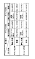
- FIG. 3 is a diagram illustrating a first table regarding scheduling by the radio base station according to the third embodiment.
- FIG. 4 is a diagram illustrating a second table regarding scheduling by the radio base station according to the third embodiment.
- FIG. 5 is a diagram illustrating an example of a table defining wireless terminal category information.
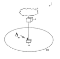
- FIG. 6 is a diagram illustrating an example of a network configuration of the wireless communication system according to each embodiment.
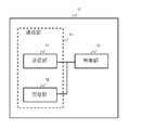
- FIG. 7 is an example of a functional configuration diagram of a radio base station in the radio communication system of each embodiment.
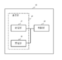
- FIG. 8 is an example of a functional configuration diagram of a wireless terminal in the wireless communication system of each embodiment.
- FIG. 9 is an example of a hardware configuration diagram of a radio base station in the radio communication system of each embodiment.
- FIG. 10 is an example of a hardware configuration diagram of a wireless terminal in the wireless communication system of each embodiment.
- radio resources including time and frequency are limited, it can be easily imagined that when radio resources are individually allocated to a large number of radio terminals, the radio resources are exhausted. For this reason, it is considered important that the radio base station allocates the same radio resource to a plurality of radio terminals so that the radio resource is efficiently used and exhaustion is avoided.
- the same radio resource assigned to a plurality of radio terminals refers to radio resources having the same time and frequency unless otherwise specified.
- the same resource block corresponding to the same frequency
- the same subframe corresponding to the same time
- MU-MIMO Multi User-Multi Input Multi Output: Multiuser MIMO
- NOMA Non-Orthogonal Multiple Access: Non-orthogonal multiple access
- MU-MIMO is an extension of conventional MIMO (Multi-Input Multi-Output).
- Conventional MIMO is applied between one radio base station and one radio terminal, whereas MU-MIMO is 1 It is applied between one radio base station and a plurality of radio terminals.
- MU-MIMO a plurality of radio communications for a radio base station and a plurality of radio terminals are spatially separated and so-called spatial multiplexing is performed.
- the radio base station performs directional radio communication using the same radio resource for each of a plurality of radio terminals having different directions. By this directivity, interference between a plurality of radio communications based on the same radio resource is suppressed, and so-called spatial multiplexing is realized.
- MU-MIMO in order to realize MU-MIMO, it is necessary in principle that the directions of a plurality of wireless terminals from the wireless base station are sufficiently separated.
- the directions of multiple wireless terminals are the same or close, even if wireless communication is performed from the wireless base station to each wireless terminal using the same wireless resource, they interfere with each other and cannot correctly decode data on the wireless terminal side Because.
- MI-MIMO a plurality of antennas are required on the radio base station side, but a single antenna may be used on the radio terminal side. Therefore, MU-MIMO has an advantage that it can be easily applied to a wireless terminal having a relatively low performance such as a sensor device.
- MU-MIMO has the advantage that the processing load on the wireless terminal side is relatively small and the power consumption is relatively small because no special processing is required on the wireless terminal side.
- NOMA multiplexes multiple wireless terminals non-orthogonally in the power axis direction.
- NOMA is applied to a plurality of wireless terminals having different distances from a wireless base station.
- wireless communication is performed with a difference in transmission power, using the same wireless resource, to a plurality of wireless terminals having different distances from the wireless base station. That is, the radio base station transmits a radio signal to which a large transmission power is allocated to a radio terminal (cell edge radio terminal) far from the radio base station using the same radio resource, and a radio signal close to the radio base station.
- the terminal nearby wireless terminal transmits a radio signal to which a small transmission power is assigned.
- the radio signal addressed to the nearby radio terminal becomes an interference signal.
- the radio signal addressed to the nearby radio terminal is assumed to have weak transmission power, the interference signal reaching the cell edge radio terminal is Relatively very small. Therefore, the cell edge radio terminal can correctly decode the radio signal addressed to itself.
- the nearby radio terminal the radio signal addressed to the cell edge radio terminal becomes an interference signal, but the radio signal addressed to the cell edge radio terminal has a relatively strong transmission power. Is very large. Therefore, the neighboring wireless terminal first decodes the signal for the cell edge wireless terminal (that is, the interference signal), and then uses the decoding result to separate the signal for the neighboring wireless terminal. Therefore, even in the nearby wireless terminal, the wireless signal addressed to itself can be correctly decoded.
- Such stepwise interference cancellation processing is called Successive Interference Cancellation (SIC: Sequential Interference Cancellation), and the hardware or function for performing SIC is called a successive interference canceller. Since the successive interference canceller is required to have high processing performance, it has been difficult to realize in the past. However, with the recent improvement in performance of wireless terminals, there is a possibility of practical use particularly in high-performance wireless terminals. However, compared to MU-MIMO, which does not require special processing on the wireless terminal side, NOMA also has a relatively large processing load on the wireless terminal side and relatively large power consumption.
- NOMA is a technology that is inherently applied to a plurality of wireless terminals with different distances from a wireless base station, but the same technology is applied to wireless terminals with the same or close distance from the wireless base station. It is also possible in principle to apply to this.
- the transmission power corresponding to the distance from the radio base station is assigned to the radio terminal that performs SIC, and the transmission power that is larger than the distance from the radio base station is allocated to the radio terminal that does not perform SIC.
- any wireless terminal can correctly decode a signal addressed to itself based on the same principle as NOMA.
- such a technique may be referred to as an extended NOMA for convenience.
- the extended NOMA When applying the extended NOMA, since excessive transmission power is allocated to a wireless terminal that does not perform SIC, the communication efficiency from the viewpoint of transmission power decreases. However, according to the extended NOMA, since the same radio resource can be allocated to a plurality of radio terminals, it is considered effective from the viewpoint of radio resource utilization efficiency.
- NOMA is a concept including extended NOMA unless otherwise specified. That is, NOMA in the present application is a concept including original NOMA and extended NOMA.
- MU-MIMO and NOMA original NOMA or extended NOMA
- NOMA original NOMA or extended NOMA
- MU-MIMO consumes less power, so when radio base stations schedule radio resources, MU-MIMO priority should be set relatively high it is conceivable that.
- MU-MIMO requires a condition that directions from a radio base station of a plurality of radio terminals are different.
- the original NOMA can be applied if the distance between multiple wireless terminals is long, and the extended NOMA can be applied if the distance is short.
- the condition that a nearby wireless terminal can perform SIC that is, relatively high performance
- NOMA at least one of multiple wireless terminals that are close to each other can perform SIC. Conditions are needed. Therefore, NOMA cannot cover all cases where MU-MIMO cannot be applied.
- MU-MIMO should be preferentially applied from the viewpoint of power consumption.
- MU-MIMO requires a condition that directions from a radio base station of a plurality of radio terminals are different, there are not a few scenes that cannot be applied, and it is desirable that this point be improved.
- the inventor of the present invention has come up with the present invention by examining the problems of the comparative examples described above.
- the first embodiment is a radio base station, and in the first case where the difference in direction from a plurality of radio terminals from the radio base station is equal to or greater than a first predetermined value, Wireless communication is performed using user MIMO, a difference in direction of the plurality of wireless terminals from the wireless base station is less than the first predetermined value, and a distance between the plurality of wireless terminals is a second predetermined value.
- the difference between the second case in which the one closer to the radio base station of the plurality of radio terminals includes a successive interference canceller and the difference in direction from the radio base station of the plurality of radio terminals A third case in which the distance between the plurality of wireless terminals is less than the second predetermined value, and at least one of the plurality of wireless terminals includes a successive interference canceller; In either case, N for the plurality of wireless terminals In a fourth case in which MA is applied and wireless communication is performed and none of the first case, the second case, and the third case is performed, different time-frequency resources are assigned to the plurality of wireless terminals.
- a control unit that performs the used wireless communication and in the fourth case, the control unit, when the relative speed of the plurality of wireless terminals is equal to or greater than a third predetermined value, On the other hand, it is based on a radio base station that performs radio communication using multiuser MIMO without performing radio communication using different time-frequency resources.
- the direction of two radio terminals from the radio base station is close, one is located in the vicinity of the radio base station and the other is located at the cell edge, and the neighboring radio terminal performs SIC
- the difference between the directions of the two wireless terminals from the wireless base station is less than the first predetermined value, and the distance between the two wireless terminals is greater than or equal to the second predetermined value,
- the one closer to the wireless base station is not equipped with a successive interference canceller.
- FIG. 1A is a diagram showing such a situation.
- the radio base station 10 is going to perform radio communication with two radio terminals 20 that are close to each other from the radio base station.
- the two wireless terminals 20 include a nearby wireless terminal 20a closer to the wireless base station 10 and a cell edge wireless terminal 20b farther away.
- FIG. 1B illustrates such a situation.
- the functions of the two radio terminals 20 from the radio base station 10 are close, one is located in the vicinity and the other is located at the cell edge, and the neighboring radio terminal 20a performs SIC.
- the two wireless terminals 20 are close to each other from the wireless base station 10, the two wireless terminals 20 are also close to each other from the wireless base station 10, and at least one of the wireless terminals 20 is connected to the wireless base station 10. The same can be said in a situation where the terminal 20 has a function of performing SIC.
- the magnitude of the relative speed of the two wireless terminals 20 is small. If it is equal to or greater than the predetermined value, in other words, when at least one of the two wireless terminals 20 is moving, MU-MIMO is applied to the two wireless terminals 20. As a result, in the comparative example described above, MU-MIMO can be applied in the first embodiment in some cases where neither MU-MIMO nor NOMA can be applied.
- the second embodiment is the radio base station 10 of the first embodiment, and in the second case or the third case, the control unit further determines the relative speed of the plurality of radio terminals 20. Is greater than or equal to the third predetermined value, based on the radio base station 10 that performs radio communication applying multi-user MIMO without performing radio communication applying NOMA to the plurality of radio terminals 20.
- NOMA original NOMA or extended NOMA
- the directions of the two radio terminals 20 from the radio base station 10 are close, one is located in the vicinity and the other is located at the cell edge, and the neighboring radio terminal 20a performs SIC
- MU-MIMO cannot be applied at that time, and NOMA must be applied.
- NOMA must be applied.
- the directions of the two radio terminals 20 from the radio base station 10 may be shifted, and MU-MIMO may be applicable. . That is, even if MU-MIMO cannot be applied at a certain point in time, MU-MIMO may be applicable (after a relatively short time).
- the directions of the two radio terminals 20 from the radio base station 10 are close, the positions of the two radio terminals 20 from the radio base station 10 are also close, and at least one radio terminal 20 performs SIC.
- the magnitude of the relative speed of the two wireless terminals 20 is equal to or greater than a predetermined value.
- MU-MIMO is applied to the two wireless terminals 20.
- MU-MIMO has an advantage that power consumption on the wireless terminal 20 side is small compared to NOMA. Therefore, according to the second embodiment, there is a remarkable effect that the power consumption of the wireless terminal 20 can be reduced as compared with the comparative example described above.
- FIG. 2 is a diagram illustrating a processing flow of the radio base station 10 according to the third embodiment.
- This processing flow assumes a case where the radio base station 10 performs scheduling for two specific radio terminals 20 (scheduling targets), that is, radio resource allocation.
- the radio base station 10 can select two specific units from all the subordinate radio terminals 20 in each transmission time interval (TTI) and execute the process flow of FIG. 2 (that is, the process flow of FIG. 2 is This is performed for each combination of two specific wireless terminals 20).
- TTI corresponds to a subframe (1 millisecond).
- the radio base station 10 acquires information about the radio terminal 20 (hereinafter referred to as terminal information) for each specific two radio terminals 20 in S101.
- the terminal information includes at least information about the direction of the radio terminal 20 from the radio base station 10 (hereinafter referred to as direction information) and information about the distance of the radio terminal 20 from the radio base station 10 (hereinafter distance information). ), Information on the presence / absence of the canceller in the wireless terminal 20 (hereinafter referred to as canceller information), and information on the moving speed of the wireless terminal 20 (hereinafter referred to as speed information).
- the direction information is information regarding the distance of the wireless terminal 20 from the wireless base station 10.
- the direction information may be information itself indicating the direction of the radio terminal 20 from the radio base station 10, or information for estimating the direction of the radio terminal 20 from the radio base station 10 (information for estimating the direction). ).
- various information can be used as shown below. That is, the radio base station 10 can obtain direction information by various means.
- the radio base station 10 determines the direction of the radio terminal 20 based on the feedback signal. Can be estimated.
- this feedback signal for example, PMI (Precoding Matrix Indicator) in LTE can be used.
- the radio base station 10 may estimate the direction of the radio terminal 20 by measuring the uplink reference signal (uplink pilot signal) transmitted from each radio terminal 20 (in this case, however, Note that the wireless communication system needs to employ TDD (Time Division Division Duplex) from the viewpoint of the symmetry of the communication path).
- the wireless terminal 20 includes a GPS (Global Positioning System) or the like, the wireless base station 10 can also estimate the direction (position) of the wireless terminal 20 based on the positioning information.
- the distance information is information related to the distance of the wireless terminal 20 from the wireless base station 10.
- the distance information may be information indicating the distance from the radio base station 10 of the radio terminal 20 or information for estimating the distance of the radio terminal 20 from the radio base station 10 (information that can estimate the distance). ).
- various information can be used as shown below. In other words, the radio base station 10 can acquire the distance information by various means.
- the radio base station 10 determines the distance of the radio terminal 20 based on the feedback signal. Can be estimated. As this feedback signal, for example, a measurement report in LTE can be used. Further, the radio base station 10 may estimate the direction of the radio terminal 20 by the radio base station 10 measuring the reception power of the uplink signal transmitted from each radio terminal 20. Further, when the wireless terminal 20 includes a GPS (Global Positioning System) or the like, the wireless base station 10 can also estimate the distance (position) of the wireless terminal 20 from the base station based on the positioning information. .
- GPS Global Positioning System
- Canceller information is information indicating whether or not the wireless terminal 20 has a successive interference canceller (whether or not the wireless terminal 20 has a function (capability) to perform SIC).
- the radio base station 10 can acquire the canceller information by, for example, some uplink control message from the radio terminal 20. Further, the radio base station 10 receives, for example, a control message indicating whether the radio terminal 20 is a machine type or a normal type (other than the machine type) from each radio terminal 20, and when the radio terminal 20 is a machine type, the radio terminal 20 May be regarded as having no canceller.
- an RRCConnectionRequest message that is a connection request from the radio terminal 20 to the radio base station 10
- an RRCConnectionSetupComplete message that is a connection setup completion notification
- the radio terminal 20 to the radio base station 10 are radio terminals.
- a UECapabilityInformation message for notifying 20 capabilities can be used.
- canceller information and the identifier of the radio terminal 20 are stored in association with each other, and the radio base station 10 inquires about the canceller information based on the identifier of the radio terminal 20 as necessary. It is also possible.
- IMSI International Mobile Subscriber Identity
- TMSI Temporary Mobile Subscriber Identity
- C-RANTI Cell Radio Network Temporary Identifier
- Speed information is information regarding the moving speed of the wireless terminal 20.
- the speed information may be information indicating the moving speed of the radio terminal 20, or information for estimating the moving speed of the radio terminal 20 (information that can estimate the moving speed).
- speed information various information can be used as shown below. In other words, the radio base station 10 can acquire speed information by various means.
- the radio base station 10 can acquire speed information by receiving from each radio terminal 20 a control message indicating whether it is a fixed radio terminal 20 or a mobile radio terminal 20.
- the wireless terminal 20 needs to recognize whether it is the mobile wireless terminal 20 or the fixed wireless terminal 20, but this may be stored in advance as information by the wireless terminal 20, or the wireless terminal 20. However, it may be determined based on an actual speed estimated based on an inertial sensor or GPS.
- the radio base station 10 receives, for example, a control message indicating whether the radio terminal 20 is a machine type or a normal type (other than a machine type) from each radio terminal 20, and when the radio terminal 20 is a normal type, the radio terminal 20 May be considered as moving.
- the radio base station 10 may receive a control message indicating the actual speed itself estimated by the radio terminal 20 based on an inertial sensor or GPS from the radio terminal 20.
- the above-described RRCConnectionRequest message, RRCConnectionSetupComplete message, UECapabilityInformation message, or the like can be used as a control message for notifying speed information from the radio terminal 20 to the radio base station 10, and PUCCH (Physical Uplink) It is also possible to use an uplink control signal on (Control Channel: physical uplink control channel).
- the radio base station 10 acquires each terminal information (direction information, distance information, canceller information, speed information), but even if these are acquired collectively (in one message or signal). It may be obtained at different timings (in different messages or signals). These messages or signals may be transmitted spontaneously by the wireless terminal 20 or may be transmitted by the wireless terminal 20 in response to a request signal from the wireless base station 10.
- the wireless terminal 20 when transmitting the terminal information, the wireless terminal 20 also transmits the identifier of the wireless terminal 20 itself to the wireless base station 10.
- the radio base station 10 can handle each radio terminal 20 in association with each terminal information corresponding thereto.
- an identifier of the radio terminal 20 for example, IMSI, TMSI, C-RANTI, etc. described above can be used.
- step S102 the radio base station 10 determines whether or not the directions of the specific two radio terminals 20 from the radio base station 10 are sufficiently separated (whether the direction is far). This determination is performed based on the direction information acquired by the radio base station 10 in S101. At this time, the radio base station 10 determines whether or not the difference between the directions (estimated values) of the two radio terminals 20 is less than the first predetermined value, thereby sufficiently separating the directions of the two radio terminals 20. It can be determined whether or not.
- the direction of the wireless terminal 20 may be one-dimensional, or may be determined in two dimensions, for example, a horizontal direction and a vertical direction.
- the radio base station 10 determines to apply MU-MIMO to the two radio terminals 20 that have been determined in S102 if the direction from the radio base station 10 is sufficiently far away. . Since these radio terminals 20 are far away from the radio base station 10, MU-MIMO with high priority can be applied among the means for allocating the same radio resources to a plurality of radio terminals 20 (because of low power consumption). That's why.
- the radio base station 10 has two radio terminals for the two radio terminals 20 that have been determined in S102 that the direction from the radio base station 10 is not sufficiently separated. It is determined whether the distance between 20 is sufficiently large (whether the distance is far). This determination is performed based on the distance information acquired by the radio base station 10 in S101. At this time, the radio base station 10 determines whether or not the distance between the two radio terminals 20 is sufficiently long by determining whether or not the difference in distance between the two radio terminals 20 is less than a second predetermined value. It can be determined whether or not.
- the radio base station 10 determines whether the difference between the received power (dbm) of the two radio terminals 20 is less than a second predetermined value. By doing so, it can be determined whether or not the distance between the two wireless terminals 20 is sufficiently large.
- the wireless base station 10 performs further determination based on the canceller information and speed information acquired in S101 for the two wireless terminals 20 that have been determined in S104 if the distance is sufficiently long.
- FIG. 3 is a diagram showing a first table regarding scheduling by the radio base station 10 in the third embodiment.
- the first table shown in FIG. 3 is a case where the directions of the two radio terminals 20 from the radio base station 10 are not sufficiently separated, and the distance between the two radio terminals 20 is A scheduling mode (radio resource allocation method) for the two radio terminals 20 when the two radio terminals 20 are sufficiently separated is shown for each classification (condition) of the two radio terminals 20.
- the vertical axis corresponds to the first wireless terminal 20 (neighboring wireless terminal 20 a) that is close to the wireless base station 10 among the two wireless terminals 20, and the horizontal axis is wireless among the two wireless terminals 20.
- Presence / absence of canceller in FIG. 3 is a parameter indicating whether or not the wireless terminal 20 has a successive interference canceller (whether or not the wireless terminal 20 has a function (capability) to perform SIC).
- Corresponding to the canceller information acquired in S101. 3 is a parameter indicating the movement speed of the wireless terminal 20, and can be obtained from the speed information acquired in S101.
- the moving speed is classified into “stationary / low speed” and “moving”.
- the speed information acquired in S101 indicates that the moving speed is less than 5 km / h, it is assumed that the “moving speed” in FIG.
- the “moving speed” may be “moving”.
- S105 is a case where the directions of the two radio terminals 20 from the radio base station 10 are not sufficiently separated, and the distance between the two radio terminals 20 is sufficient. It corresponds to the case where it is far away.
- the radio base station 10 determines the scheduling mode of the two radio terminals 20 based on the first table shown in FIG. 3 for the two radio terminals 20 that satisfy such conditions.
- the radio base station 10 has two radio terminals 20 that are both “stationary / low speed” and the radio terminal 20a closer to the radio base station 10 is “canceller present”. The process proceeds to S107.
- the radio base station 10 allocates the same radio resource to the two radio terminals 20, and applies the original NOMA.
- the radio base station 10 has two radio terminals 20 that are both “stationary / low speed” and the radio terminal 20a that is closer to the radio base station 10 is “no canceller”. The process proceeds to S108. In S108, the radio base station 10 determines that another radio resource is allocated to the two radio terminals 20 (that is, neither MU-MIMO nor NOMA is performed).
- the radio base station 10 proceeds to S109 in cases other than the above.
- the radio base station 10 allocates the same radio resource to the two radio terminals 20, and determines to apply MU-MIMO. In other words, the radio base station 10 allocates the same radio resource to the two radio terminals 20 when at least one of the two radio terminals 20 is moving. , Decide to apply MU-MIMO.
- the radio base station 10 makes further determination based on the canceller information and the speed information acquired in S101 to the two radio terminals 20 that have been determined in S104 that the distance is not sufficiently long. Do.
- FIG. 4 is a diagram showing a second table regarding scheduling by the radio base station 10 in the third embodiment.
- the second table shown in FIG. 4 is a case where the directions of the two wireless terminals 20 from the wireless base station 10 are not sufficiently separated, and the distance between the two wireless terminals 20 is also The scheduling mode (how to allocate radio resources) of the two radio terminals 20 when they are not sufficiently separated is shown for each classification (condition) of the two radio terminals 20.
- the vertical axis and the horizontal axis correspond to the two wireless terminals 20, respectively, and they are classified by “presence / absence of canceller” and “moving speed”. ing.
- S106 is a case where the directions of the two wireless terminals 20 from the wireless base station 10 are not sufficiently separated, and the distance between the two wireless terminals 20 is also sufficiently separated. It corresponds to the case where it is not.
- the radio base station 10 determines the scheduling mode of the two radio terminals 20 based on the second table shown in FIG. 4 for the two radio terminals 20 that satisfy such a condition.
- step S106 the radio base station 10 determines that if the two radio terminals 20 are both “stationary / low speed” and at least one of the two radio terminals 20 is “canceller present”, Proceed to In S110, the radio base station 10 assigns the same radio resource to the two radio terminals 20, and applies the extended NOMA.
- the radio base station 10 determines that the two radio terminals 20 are “stationary / low speed” and the two radio terminals 20 are “no canceller”. Proceed to In S111, the radio base station 10 determines that another radio resource is allocated to the two radio terminals 20 (that is, neither MU-MIMO nor NOMA is performed).
- the radio base station 10 proceeds to S112 in cases other than the above.
- the radio base station 10 allocates the same radio resource to the two radio terminals 20, and determines to apply MU-MIMO.
- the radio base station 10 allocates the same radio resource to the two radio terminals 20 when at least one of the two radio terminals 20 is moving. , Decide to apply MU-MIMO.
- the reason for applying MU-MIMO when at least one of the two wireless terminals 20 is moving is as described in the first embodiment or the like. Even if the directions of the two wireless terminals 20 from the wireless base station 10 are not sufficiently separated, if the relative speed of the two wireless terminals 20 is equal to or higher than a predetermined value, the two wireless terminals 20 This is because the direction of the wireless terminal 20 from the wireless base station 10 is considered to be shifted (after a predetermined time has elapsed), and MU-MIMO can be applied. Therefore, it should be noted that it is desirable to allocate radio resources after a predetermined time or more to the MU-MIMO determined in S109 and S112 (as opposed to the MU-MIMO determined in S103). There is no such restriction).
- the scheduling mode is determined based on the combination of the absolute movement speeds of the two wireless terminals 20.
- the combination of the absolute moving speeds of the two wireless terminals 20 as described above can be considered to represent the relative speeds of the two wireless terminals 20 approximately.
- the scheduling mode can be determined after actually obtaining the relative speeds of the two wireless terminals 20.
- MU-MIMO is not performed when the moving speeds of the two wireless terminals 20 are both “stationary / low speed”.
- the moving speed may be further classified into “stationary” and “low speed”, and MU-MIMO may be performed when both of the two wireless terminals 20 are low speed. This is because when the two wireless terminals 20 are moving at low speed, the relative speed between the wireless terminals 20 is such that one wireless terminal 20 is stationary and the other wireless terminal 20 is moving at high speed.
- FIG. 5 shows an example of a table defining such terminal category information.
- the categories of the wireless terminals 20 are indexed, and each wireless terminal 20 corresponds to one of 15 categories.
- the column of “multiple access” in FIG. 5 corresponds to canceller information, “orthogonal” indicates no sequential interference canceller (that is, always performs orthogonal multiple access), and “non-orthogonal” indicates that there is a sequential interference canceller (but orthogonal multiple access). "Orthogonal / non-orthogonal” means that there is a successive interference canceller (but orthogonal multiple access is also possible).
- the columns of “wireless terminal 20 type” and “movement speed” correspond to speed information.
- the radio terminal 20 type is information indicating whether the radio terminal 20 is a machine type (MTC: “Machine” Type “Communication”) or a normal type (Normal).
- the moving speed is information that is set only for the machine type wireless terminal 20 and indicates the moving speed of the wireless terminal 20. Note that the table as shown in FIG. 5 may be held (that is, shared) by both the radio terminal 20 and the radio base station 10, or may be held only by the radio base station 10. .
- the radio base station 10 applies the original NOMA to the two radio terminals 20, and in this case, the transmission power allocated to the two radio terminals 20 is determined by a general method ( (Closed loop control based on feedback of received power in the radio terminal 20). However, in the present embodiment, the transmission power allocated to the two wireless terminals 20 may be corrected as follows when the original NOMA is applied.
- the difference (absolute value) of the transmission power is equal to or greater than a predetermined value.
- the predetermined value here can be appropriately determined as long as it is larger than the above-described second predetermined value (used in S104), and can be set to 3db, for example.
- the difference in transmission power is less than a predetermined value
- the transmission power of the radio terminal 20 (cell edge radio terminal 20) far from the radio base station 10 is corrected so as to be amplified by the predetermined value.
- the transmission power difference is less than the predetermined value, it means that there is a margin in the transmission power of the radio base station 10, so by amplifying the transmission power of the cell edge radio terminal 20, The effect of improving the communication gain can be expected.
- the fourth embodiment is an embodiment corresponding to the superordinate concept of the first embodiment and the second embodiment. More specifically, the fourth embodiment is the radio base station 10, and in the first case where the difference in direction from the radio base station 10 of the plurality of radio terminals 20 is greater than or equal to a first predetermined value, Wireless communication using multi-user MIMO is performed with respect to the plurality of wireless terminals 20, and a difference in direction of the plurality of wireless terminals 20 from the wireless base station 10 is less than the first predetermined value, In the second case where the magnitude of the relative speed of the wireless terminal 20 is greater than or equal to the second predetermined value, wireless communication using multi-user MIMO is performed with respect to the plurality of wireless terminals 20, and the plurality of wireless terminals In a third case where the difference in direction of 20 from the radio base station 10 is less than the first predetermined value and the magnitude of the relative speed of the plurality of radio terminals 20 is less than a second predetermined value, Multi-user MIMO is applied to the plurality of radio terminal
- the wireless base station 10 When the MU-MIMO cannot be applied to the two wireless terminals 20, the wireless base station 10 according to the first embodiment or the second embodiment first determines whether NOMA (original NOMA or extended NOMA) is applicable. Yes. When NOMA cannot be applied to the two wireless terminals 20, MU-MIMO is applied to the two wireless terminals 20 without assigning another resource under a predetermined condition. On the other hand, when the MU-MIMO cannot be applied to the two wireless terminals 20, the wireless base station 10 according to the fourth embodiment does not determine whether NOMA can be applied or not under the predetermined condition. MU-MIMO is applied without assigning another resource to one wireless terminal 20.
- NOMA original NOMA or extended NOMA
- speed information related to the moving speed of the wireless terminal 20 is handled.
- the speed information may be set according to the nature of application software that the wireless terminal 20 operates. For example, when the application software controls communication and movement with an automatic robot or drone, if the movement state (movement speed or presence / absence of movement stoppage) is clear, the speed set based on it The information may be notified to the radio base station.
- the radio base station 10 acquires all or part of the terminal information from the radio terminal 20, which is based on the contract information of the radio terminal 20 in the network control device on the network side. It is also good to get it.
- an HSS Home Subscriber Server
- the LTE system can be operated as such a network control device.
- the wireless terminal 20 when transmitting the terminal information, the wireless terminal 20 also transmits the identifier of the wireless terminal 20 itself to the wireless base station 10. At this time, the radio base station 10 can newly generate the identifier of the radio terminal 20 and notify the radio terminal 20 to update the identifier of the radio terminal 20.
- the type of terminal information of each radio terminal 20 and a set of “time zone” and “use frequency” are stored in association with each other.
- the “time zone” is, for example, either daytime or nighttime.
- the “use frequency” is, for example, one of a first frequency (for example, 2 GHz) used in the LTE system or the like and a second frequency (for example, 30 GHz) that is a millimeter wave band.
- the first frequency band is easy to diffract and reflect, so it is suitable for non-line-of-sight (NLOS: Non Line Of Sight) communication, while the second frequency band is highly visible (LOS: Line Of Sight) Suitable for communication. Therefore, by using the association as described above on the wireless base station 10 side, for example, wireless communication is performed using the first frequency in the daytime when there are many people and cars, and the wireless terminal is used at night when there are few people and cars. Control that performs wireless communication using the second frequency when the moving speed of 20 is below a predetermined value, and performs wireless communication using the first frequency even when the moving speed of the wireless terminal 20 is equal to or higher than a predetermined value at night Can be performed.
- the radio base station 10 can also switch the use frequency as described above when the radio quality (propagation environment) with the radio terminal 20 is deteriorated.
- index values for detecting radio quality degradation for example, received field strength (RRSI: Received Signal Strength Indicator), reference signal received power (RSRP: Reference Signal Received Power), reference signal received quality (RSRQ: Reference Signal Received Quality) can be used.
- RTSI Received Signal Strength Indicator
- RSRP Reference Signal Received Power
- RSRQ Reference Signal Received Quality
- the radio terminal 20 reports these index values for each frequency to be measured to the radio base station 10, so that the radio base station 10 communicates with the radio terminal 20. You can understand the quality.
- the wireless terminal 20 measures the number of drops (per unit time) of these index values for each frequency to be measured, and the wireless terminal 20 reports the measured number of drops to the wireless base station 10,
- the radio base station 10 may grasp the radio quality with the radio terminal 20.
- the wireless communication system 1 includes a wireless base station 10 and a wireless terminal 20.
- the radio base station 10 forms a cell C10.
- the radio terminal 20 exists in the cell C10. Note that in this application, the radio base station 10 may be referred to as a “transmitting station” and the radio terminal 20 may be referred to as a “receiving station”.
- the wireless base station 10 is connected to the network device 3 via a wired connection, and the network device 3 is connected to the network 2 via a wired connection.
- the radio base station 10 is provided so as to be able to transmit and receive data and control information to and from other radio base stations via the network device 3 and the network 2.
- the radio base station 10 may separate the radio communication function with the radio terminal 20 and the digital signal processing and control function to be a separate device.
- a device having a wireless communication function is referred to as RRH (Remote Radio Head)
- BBU Base Band Unit
- the RRH may be installed overhanging from the BBU, and may be wired with an optical fiber between them.
- the radio base station 10 is a radio base station of various scales besides a small radio base station (including a micro radio base station, a femto radio base station, etc.) such as a macro radio base station and a pico radio base station. Good.
- the relay station transmission / reception with the wireless terminal 20 and its control
- the wireless base station 10 of the present application It is good.
- the wireless terminal 20 communicates with the wireless base station 10 by wireless communication.
- the wireless terminal 20 may be a wireless terminal such as a mobile phone, a smartphone, a PDA (Personal Digital Assistant), a personal computer (Personal Computer), various devices or devices (such as sensor devices) having a wireless communication function.
- a relay station that relays wireless communication between the wireless base station 10 and the wireless terminal is used, the relay station (transmission / reception with the wireless base station 10 and its control) is also included in the wireless terminal 20 of the present application. Also good.
- the network device 3 includes, for example, a communication unit and a control unit, and these components are connected so that signals and data can be input and output in one direction or in both directions.
- the network device 3 is realized by a gateway, for example.
- the communication unit is realized by an interface circuit
- the control unit is realized by a processor and a memory.
- each component of the wireless base station and the wireless terminal is not limited to the aspect of the first embodiment, and all or a part thereof may depend on various loads, usage conditions, and the like. Also, it can be configured to be functionally or physically distributed and integrated in arbitrary units.
- the memory may be connected via a network or a cable as an external device of a wireless base station or a wireless terminal.
- FIG. 7 is a functional block diagram showing the configuration of the radio base station 10. As illustrated in FIG. 7, the radio base station 10 includes a transmission unit 11, a reception unit 12, and a control unit 13. Each of these components is connected so that signals and data can be input and output in one direction or in both directions.
- the transmission unit 11 and the reception unit 12 are collectively referred to as a communication unit 14.
- the transmission unit 11 transmits a data signal and a control signal by wireless communication via an antenna.
- the antenna may be common for transmission and reception.
- the transmitter 11 transmits a downlink signal via, for example, a downlink data channel or a control channel.
- the downlink data channel includes, for example, a physical downlink shared channel PDSCH (Physical Downlink Shared Channel).
- the downlink control channel includes, for example, a physical downlink control channel PDCCH (Physical Downlink Control Channel).
- the signal to be transmitted is, for example, an L1 / L2 control signal transmitted on the control channel to the connected wireless terminal 20, a user data signal transmitted on the data channel to the connected wireless terminal 20, or RRC (Radio Resource Control). ) Contains control signals.
- the signal to be transmitted includes, for example, a reference signal used for channel estimation and demodulation.
- the signal transmitted by the transmission unit 11 includes all signals transmitted by the radio base station 10 in the above-described embodiments and modifications.
- the receiving unit 12 receives the data signal and the control signal transmitted from the wireless terminal 20 through the first wireless communication via the antenna.
- the receiving unit 12 receives an uplink signal via, for example, an uplink data channel or a control channel.
- the uplink data channel includes, for example, a physical uplink shared channel PUSCH (Physical Uplink Shared Channel).
- the uplink control channel includes, for example, a physical uplink control channel PUCCH (Physical Uplink Control Channel).
- the received signal is, for example, an L1 / L2 control signal transmitted on the control channel from the connected wireless terminal 20, a user data signal transmitted on the data channel from the connected wireless terminal 20, or RRC (Radio Resource Control). ) Contains control signals.
- the received signal includes, for example, a reference signal used for channel estimation and demodulation.
- the signals received by the receiving unit 12 include all signals received by the radio base station 10 in the above-described embodiments and modifications.
- the control unit 13 outputs data to be transmitted and control information to the transmission unit 11.
- the control unit 13 inputs received data and control information from the reception unit 12.
- the control unit 13 acquires data and control information from the network device 3 and other wireless base stations via a wired connection or a wireless connection. In addition to these, the control unit performs various controls related to various transmission signals transmitted by the transmission unit 11 and various reception signals received by the reception unit 12.
- the process controlled by the control unit 13 includes all processes executed by the radio base station 10 in the above-described embodiments and modifications.
- FIG. 8 is a functional block diagram showing the configuration of the wireless terminal 20.
- the wireless terminal 20 includes a transmission unit 21, a reception unit 22, and a control unit 23. Each of these components is connected so that signals and data can be input and output in one direction or in both directions.
- the transmitter 21 and the receiver 22 are collectively referred to as a communication unit 24.
- the transmission unit 21 transmits a data signal and a control signal by wireless communication via an antenna.
- the antenna may be common for transmission and reception.
- the transmission unit 21 transmits an uplink signal via, for example, an uplink data channel or a control channel.
- the uplink data channel includes, for example, a physical uplink shared channel PUSCH (Physical Uplink Shared Channel).
- the uplink control channel includes, for example, a physical uplink control channel PUCCH (Physical Uplink Control Channel).
- the signal to be transmitted is, for example, an L1 / L2 control signal transmitted on the control channel to the radio base station 10 to be connected, a user data signal transmitted on the data channel to the radio base station 10 to be connected, or RRC (Radio Resource Control). ) Contains control signals.
- the signal to be transmitted includes, for example, a reference signal used for channel estimation and demodulation.
- the signal transmitted by the transmission unit 21 includes all signals transmitted by the wireless terminal 20 in each of the above embodiments and modifications.
- the receiving unit 22 receives a data signal and a control signal transmitted from the radio base station 10 by radio communication via an antenna.
- the receiving unit 22 receives a downlink signal via, for example, a downlink data channel or a control channel.
- the downlink data channel includes, for example, a physical downlink shared channel PDSCH (Physical Downlink Shared Channel).
- the downlink control channel includes, for example, a physical downlink control channel PDCCH (Physical Downlink Control Channel).
- the received signal is, for example, an L1 / L2 control signal transmitted from the connected radio base station 10 on the control channel, a user data signal transmitted from the connected radio base station 10 on the data channel, or RRC (Radio Resource Control). ) Contains control signals.
- the received signal includes, for example, a reference signal used for channel estimation and demodulation.
- Signals received by the receiving unit 22 include all signals received by the wireless terminal 20 in the above embodiments and modifications.
- the control unit 23 outputs data to be transmitted and control information to the transmission unit 21.
- the control unit 23 inputs received data and control information from the reception unit 22.
- the control unit 23 acquires data and control information from the network device 3 and other wireless base stations via a wired connection or a wireless connection. In addition to these, the control unit performs various controls related to various transmission signals transmitted by the transmission unit 21 and various reception signals received by the reception unit 22.
- the process controlled by the control unit 23 includes all processes executed by the wireless terminal 20 in the above-described embodiments and modifications.
- FIG. 9 is a diagram illustrating a hardware configuration of the radio base station 10.
- the radio base station 10 includes, as hardware components, an RF (Radio Frequency) circuit 32 including an antenna 31, a CPU (Central Processing Unit) 33, and a DSP (Digital Signal Processor) 34, for example. And a memory 35 and a network IF (Interface) 36.
- the CPU is connected so that various signals and data can be input / output via the bus.
- the memory 35 includes at least one of RAM (Random Access Memory) such as SDRAM (Synchronous Dynamic Random Access Memory), ROM (Read Only Memory), and flash memory, and stores programs, control information, and data.
- RAM Random Access Memory
- SDRAM Synchronous Dynamic Random Access Memory
- ROM Read Only Memory
- flash memory stores programs, control information, and data.
- the transmission unit 11 and the reception unit 12 are realized by the RF circuit 32 or the antenna 31 and the RF circuit 32, for example.
- the control unit 13 is realized by, for example, a CPU 33, a DSP 34, a memory 35, a digital electronic circuit (not shown), and the like. Examples of digital electronic circuits include ASIC (Application Specific Integrated Circuit), FPGA (Field-Programming Gate Array), and LSI (Large Scale Integration).
- FIG. 10 is a diagram illustrating a hardware configuration of the wireless terminal 20.
- the wireless terminal 20 includes, for example, an RF circuit 42 including an antenna 41, a CPU 43, and a memory 44 as hardware components. Further, the wireless terminal 20 may have a display device such as an LCD (Liquid Crystal Display) connected to the CPU 43.
- the memory 44 includes at least one of RAM such as SDRAM, ROM, and flash memory, for example, and stores programs, control information, and data.
- the transmission unit 21 and the reception unit 22 are realized by, for example, the RF circuit 42 or the antenna 41 and the RF circuit 42.
- the control unit 23 is realized by, for example, the CPU 43, the memory 44, a digital electronic circuit (not shown), and the like. Examples of digital electronic circuits include ASIC, FPGA, LSI, and the like.
- wireless communication system 1 wireless communication system 2 network 3 network device 10 wireless base station C10 cell 20 wireless terminal
Landscapes
- Engineering & Computer Science (AREA)
- Computer Networks & Wireless Communication (AREA)
- Signal Processing (AREA)
- Mobile Radio Communication Systems (AREA)
Abstract
開示の技術は、大量の無線端末に対して無線リソースを効率的に割り当てることができる無線基地局等を提供することを目的とする。 上述した目的を達成するために、開示の基地局は、複数端末の該基地局からの方向の差が第1所定値以上である場合に、該複数端末に対してMU-MIMOを適用し、該複数端末の該基地局からの方向の差が前記第1所定値未満であって、該複数端末の間の距離が第2所定値以上であって、該複数端末のうちで該基地局に近い方が逐次干渉キャンセラを備える場合等に、該複数端末に対してNOMAを適用し、上述したいずれの場合でもない所定の場合に、該複数端末に対して異なる時間周波数リソースを割り当てる制御部を備え、前記所定の場合に前記制御部は、前記複数端末の相対速度の大きさが第3所定値以上である場合には、該複数端末に対して、異なる時間周波数リソースを割り当てることなく、MU-MIMOを適用する。
Description
本発明は、無線基地局、無線通信システム、および無線通信スケジューリング方法に関する。
近年、携帯電話システム(セルラーシステム)等の無線通信システムにおいて、無線通信の更なる高速化・大容量化等を図るため、次世代の無線通信技術について議論が行われている。例えば、標準化団体である3GPP(3rd Generation Partnership Project)では、LTE(Long Term Evolution)と呼ばれる通信規格や、LTEの無線通信技術をベースとしたLTE-A(LTE-Advanced)と呼ばれる通信規格が提案されている。
3GPPにおいては、第5世代移動通信システム(いわゆる5Gシステム)の標準化に関する議論が2015年9月に本格的に開始された。今後は、超高速・大容量といった従来の要件に加え、IoT(Internet of Things)に向けた新たな要件を満足する移動通信システムを実現すべく、活発な議論が行われることが期待される。
5Gシステムに対するこのような新たな要件の一つとして、超大量接続の実現が挙げられる。IoTの世界では、例えば各種のセンサ装置、家電、自動車等のように、あらゆるものがネットワーク接続されることが想定されている。そのため、5Gシステムに対しては、大量の無線端末接続に耐えられるようなシステム設計が要求されるとともに、大量に接続された無線端末を効率よく処理するためのスケジューリング等の技術の重要性も益々高まっていくものと考えられる。
上述したように、5Gシステムにおける議論はまだ開始されたばかりであり、当面は基本的なシステム設計が主に議論されていくことになると考えられる。そのため、大量の無線端末に対して無線リソースを効率的に割り当てるような、オペレーター内において適宜実装される技術については、議論があまり進んでいないのが実情である。しかしながら、こうした技術が後々必要となることは明白であることから、将来を見据えて検討を行っておくことが望ましいと考えられる。
開示の技術は、上記に鑑みてなされたものであって、大量の無線端末に対して無線リソースを効率的に割り当てることができる無線基地局、無線通信システム、および無線通信スケジューリング方法を提供することを目的とする。
上述した課題を解決し、目的を達成するために、開示の無線基地局は、複数の無線端末の該無線基地局からの方向の差が第1所定値以上である第1の場合において、該複数の無線端末に対してマルチユーザMIMOを適用した無線通信を行い、該複数の無線端末の該無線基地局からの方向の差が前記第1所定値未満であって、該複数の無線端末の間の距離が第2所定値以上であって、該複数の無線端末のうちで該無線基地局に近い方が逐次干渉キャンセラを備える第2の場合と、該複数の無線端末の該無線基地局からの方向の差が前記第1所定値未満であって、該複数の無線端末の間の距離が前記第2所定値未満であって、該複数の無線端末のうちの少なくとも一方が逐次干渉キャンセラを備える第3の場合とのいずれかである場合において、該複数の無線端末に対してNOMAを適用した無線通信を行い、前記第1の場合と前記第2の場合と前記第3の場合とのいずれでもない第4の場合において、該複数の無線端末に対して異なる時間周波数リソースを用いた無線通信を行う制御部を備え、前記第4の場合において前記制御部は、前記複数の無線端末の相対速度の大きさが第3所定値以上である場合には、該複数の無線端末に対して、異なる時間周波数リソースを用いた無線通信を行うことなく、マルチユーザMIMOを適用した無線通信を行う。
本件の開示する無線基地局、無線通信システム、および無線通信スケジューリング方法の一つの態様によれば、大量の無線端末に対して無線リソースを効率的に割り当てることができるという効果を奏する。
以下に、本件の開示する無線基地局、無線通信システム、および無線通信スケジューリング方法の実施形態を、図面を参照しながら説明する。なお、以下の実施形態により本件の開示する無線基地局、無線通信システム、および無線通信スケジューリング方法が限定されるものではない。
[問題の所在]
まず、各実施形態を説明する前に、従来技術における問題の所在を説明する。この問題は、本願発明者が従来技術を仔細に検討した結果として新たに見出したものであり、従来は知られていなかったものであることに注意されたい。
まず、各実施形態を説明する前に、従来技術における問題の所在を説明する。この問題は、本願発明者が従来技術を仔細に検討した結果として新たに見出したものであり、従来は知られていなかったものであることに注意されたい。
上述したように、大量の無線端末に対して無線リソースを効率的に割り当てる技術が、将来的に重要性を増していくものと考えられる。ここで、時間と周波数とから成る無線リソースは有限であるため、大量の無線端末に対してそれぞれ個別に無線リソースを割り当てた場合、無線リソースが枯渇してしまうことは容易に想像できる。そのため、無線基地局が複数の無線端末に対して同一の無線リソースを割り当てることにより、無線リソースを効率的に活用し、枯渇を回避することが重要であると考えられる。
なお、本願において、複数の無線端末に割り当てられる「同一の無線リソース」とは、特に断りが無い限り、時間及び周波数が同一の無線リソースを指すものとする。例えば、LTEにおいては、所定の条件下において、同一のサブフレーム(同一時間に対応)における同一のリソースブロック(同一周波数に対応)を複数の無線端末に割り当てることができる。
さて、無線基地局が複数の無線端末に対して同一の無線リソースを割り当てることができる要素技術として、ここではMU-MIMO(Multi User - Multi Input Multi Output:マルチユーザMIMO)とNOMA(Non-Orthogonal Multiple Access:非直交多元接続)とを順に紹介する。
MU-MIMOは従来のMIMO(Multi Input Multi Output)を拡張した技術であり、従来のMIMOが1つの無線基地局と1つの無線端末との間に適用されるのに対し、MU-MIMOは1つの無線基地局と複数の無線端末との間に適用される。MU-MIMOは、無線基地局と複数無線端末それぞれに対する複数の無線通信が空間的に分離され、いわゆる空間多重が行われる。MU-MIMOを行う場合、無線基地局は、方向が異なる複数の無線端末それぞれに対し、同一の無線リソースを用いて指向性のある無線通信を行う。この指向性により、同一の無線リソースに基づく複数の無線通信間の干渉が抑制され、いわゆる空間多重が実現されるのである。
このように、MU-MIMOを実現するためには、原理上、複数の無線端末の無線基地局からの方向が十分に離れていることが必要となる。複数無線端末の方向が同じまたは近い場合、無線基地局からそれぞれの無線端末へ同一無線リソースを用いて無線通信を行ったとしても、それらは互いに干渉し合い、無線端末側で正しくデータを復号できないためである。しかしながら、MI-MIMOを行う場合、無線基地局側には複数のアンテナが必要であるが、無線端末側は1本のアンテナでも構わない。したがって、MU-MIMOは、センサ装置等のように性能が比較的低い無線端末に対しても容易に適用できるという利点を有している。また、MU-MIMOには、無線端末側において特別な処理が不要なため、無線端末側の処理負荷が比較的小さく、消費電力も比較的小さいという利点もある。
これに対し、NOMAは、複数無線端末を電力軸方向で非直交に多重するものである。一般的に、NOMAは無線基地局からの距離が異なる複数の無線端末に対して適用される。具体的には、NOMAを適用する場合、無線基地局からの距離が異なる複数の無線端末に対して、同一の無線リソースを用いて、送信電力に差を付けて無線通信を行う。すなわち、無線基地局は、同一の無線リソースを用いて、無線基地局から遠い無線端末(セル端無線端末)に対して大きな送信電力を割り当てた無線信号を送信するとともに、無線基地局から近い無線端末(近傍無線端末)については小さな送信電力を割り当てた無線信号を送信する。
このとき、セル端無線端末にとっては、近傍無線端末宛の無線信号は干渉信号となるが、近傍無線端末宛の無線信号は想定的に送信電力が弱いため、セル端無線端末に届く干渉信号は相対的に非常に小さい。そのため、セル端無線端末は自分宛の無線信号を正しく復号できる。一方、近傍無線端末にとっては、セル端無線端末宛の無線信号は干渉信号となるが、セル端無線端末宛の無線信号は相対的に送信電力が強いため、近傍無線端末に届く干渉信号は相対的に非常に大きい。そこで、近傍無線端末は、まずセル端無線端末向けの信号(つまり干渉信号)を復号した後に、その復号結果を利用して、近傍無線端末向けの信号を分離する。により、近傍無線端末においても、自分宛の無線信号を正しく復号できることになる。
このような段階的な干渉キャンセル処理は、Successive Interference Cancellation(SIC:逐次干渉キャンセル)と呼ばれており、SICを行うハードウェアまたは機能を逐次干渉キャンセラと呼ぶ。逐次干渉キャンセラには高い処理性能が要求されるため、従来は実現が難しかったが、近年の無線端末性能の向上に伴い、特に高性能無線端末において、実用化の目途が付きつつある。ただし、無線端末側において特別な処理が不要なMU-MIMOと比較すると、NOMAには無線端末側の処理負荷が比較的大きく、消費電力も比較的大きいという側面もある。
ところで、上述したように、NOMAは本来的には無線基地局からの距離が異なる複数の無線端末に適用する技術であるが、同様の技術を無線基地局からの距離が等しいまたは近い無線端末に対して適用することも原理的には可能である。その場合、SICを行う無線端末に対し、無線基地局からの距離に見合う送信電力を割り当てるとともに、SICを行わない無線端末に対し、無線基地局からの距離に見合うよりも大きい送信電力を割り当てる。これにより、NOMAと同様の原理により、いずれの無線端末も自分宛の信号を正しく復号できる。本願においては、便宜上、このような技術を拡張NOMAと称することがある。
拡張NOMAを適用する場合、SICを行わない無線端末に対しては、過剰な送信電力が割り当てられることになるため、送信電力の観点からの通信効率は落ちることになる。しかしながら、拡張NOMAによれば、複数の無線端末に対して同一の無線リソースを割り当てることができるため、無線リソースの利用効率という観点では有効であるものと考えられる。
以下では、特段の断りが無い限り、NOMAは拡張NOMAを含む概念であるものとする。すなわち、本願におけるNOMAは、本来のNOMAと拡張NOMAとを含む概念であるものとする。
さて、以上で説明したように、無線基地局が複数の無線端末に対して同一の無線リソースを割り当てることができる要素技術としては、MU-MIMOとNOMA(本来のNOMAまたは拡張NOMA)とが挙げられる。以下では、これら要素技術に基づく比較例(基準技術)を説明する。
MU-MIMOとNOMAを比較すると、MU-MIMOの方が消費電力が小さいため、無線基地局が無線リソースをスケジューリングする際には、MU-MIMOの優先順位を比較的高く設定するべきであるものと考えられる。ただし、MU-MIMOには、複数無線端末の無線基地局からの方向が異なるという条件が必要なため、適用できない場合も少なくない。MU-MIMOが適用できない場合、複数無線端末の距離が離れていれば本来のNOMAが適用でき、距離が近ければ拡張NOMAを適用できる。ただし、本来のNOMAにおいては、近傍無線端末がSICを行える(つまり比較的高性能である)という条件が必要であり、拡張NOMAにおいては、距離が近い複数無線端末の少なくとも一方がSICを行えるという条件が必要である。そのため、MU-MIMOを適用できない場合の全てをNOMAがカバーできるわけではない。
MU-MIMOとNOMAのいずれもが適用できない場合、複数無線端末に対して同一の無線リソースを割り当てることはできないことになり、やむなく、複数無線端末に対して異なる無線リソースを割り当てることになるものと考えられる。しかしながら、このような場合は、無線リソースの利用効率の観点からは好ましくはない。したがって、無線基地局により無線リソースのスケジューリングにおいては、このような場合ができるだけ少なくなるように対処することが望ましいと考えられる。
また、MU-MIMOとNOMAとを比較すると、上述したように、消費電力の観点からMU-MIMOを優先適用するべきである。しかしながら、MU-MIMOには、複数無線端末の無線基地局からの方向が異なるという条件が必要であるため、適用できない場面も少なくなく、この点も改善されると望ましい。
本願発明の発明者は、以上で述べた比較例が備える問題を検討して本願発明に想到したものである。
[第1実施形態]
第1実施形態は、無線基地局であって、複数の無線端末の該無線基地局からの方向の差が第1所定値以上である第1の場合において、該複数の無線端末に対してマルチユーザMIMOを適用した無線通信を行い、該複数の無線端末の該無線基地局からの方向の差が前記第1所定値未満であって、該複数の無線端末の間の距離が第2所定値以上であって、該複数の無線端末のうちで該無線基地局に近い方が逐次干渉キャンセラを備える第2の場合と、該複数の無線端末の該無線基地局からの方向の差が前記第1所定値未満であって、該複数の無線端末の間の距離が前記第2所定値未満であって、該複数の無線端末のうちの少なくとも一方が逐次干渉キャンセラを備える第3の場合とのいずれかである場合において、該複数の無線端末に対してNOMAを適用した無線通信を行い、前記第1の場合と前記第2の場合と前記第3の場合とのいずれでもない第4の場合において、該複数の無線端末に対して異なる時間周波数リソースを用いた無線通信を行う制御部を備え、前記第4の場合において前記制御部は、前記複数の無線端末の相対速度の大きさが第3所定値以上である場合には、該複数の無線端末に対して、異なる時間周波数リソースを用いた無線通信を行うことなく、マルチユーザMIMOを適用した無線通信を行う無線基地局に基づく。
第1実施形態は、無線基地局であって、複数の無線端末の該無線基地局からの方向の差が第1所定値以上である第1の場合において、該複数の無線端末に対してマルチユーザMIMOを適用した無線通信を行い、該複数の無線端末の該無線基地局からの方向の差が前記第1所定値未満であって、該複数の無線端末の間の距離が第2所定値以上であって、該複数の無線端末のうちで該無線基地局に近い方が逐次干渉キャンセラを備える第2の場合と、該複数の無線端末の該無線基地局からの方向の差が前記第1所定値未満であって、該複数の無線端末の間の距離が前記第2所定値未満であって、該複数の無線端末のうちの少なくとも一方が逐次干渉キャンセラを備える第3の場合とのいずれかである場合において、該複数の無線端末に対してNOMAを適用した無線通信を行い、前記第1の場合と前記第2の場合と前記第3の場合とのいずれでもない第4の場合において、該複数の無線端末に対して異なる時間周波数リソースを用いた無線通信を行う制御部を備え、前記第4の場合において前記制御部は、前記複数の無線端末の相対速度の大きさが第3所定値以上である場合には、該複数の無線端末に対して、異なる時間周波数リソースを用いた無線通信を行うことなく、マルチユーザMIMOを適用した無線通信を行う無線基地局に基づく。
第1実施形態の技術的意義を説明する。前述した比較例では、MU-MIMOとNOMA(本来のNOMAまたは拡張NOMA)のいずれもが適用できない場合、複数無線端末に対して同一の無線リソースを割り当てないが、この点について掘り下げてみる。もし、ある時点においてMU-MIMOとNOMAのいずれもが適用できない状況であっても、そのような状況が未来永劫続くとは限らないし、少しの時間を置けばそのような状況が解消されることも多いものと考えられる。
例えば、ある時点において、2台の無線端末の無線基地局からの方向が近く、一方が無線基地局の近傍に位置するとともに他方がセル端に位置しており、且つ、近傍無線端末がSICを行う機能を有しない状況を考える。換言すれば、2台の無線端末の無線基地局からの方向の差が第1所定値未満であって当該2台の無線端末の間の距離が第2所定値以上であって、当該2台の無線端末のうちで当該無線基地局に近い方が逐次干渉キャンセラを備えていない状況である。
図1Aは、このような状況を示した図である。ここで、無線基地局10は、当該無線基地局からの方向が近い2台の無線端末20と無線通信を行おうとしている。ここで、2台の無線端末20は、無線基地局10に近い方の近傍無線端末20aと、遠い方のセル端無線端末20bとから成る。
このような状況においては、確かにその時点ではMU-MIMOとNOMAのいずれもが適用できない。しかしながら、例えば2台の無線端末20の少なくとも一方が移動することにより、2台の無線端末20の無線基地局10からの方向がずれ、MU-MIMOが適用可能となる可能性も十分にありうる。換言すれば、2台の無線端末20の相対速度の大きさが第3所定値以上の場合には、MU-MIMOが適用可能となる可能性も十分にありうる。
すなわち、ある時点ではMU-MIMOとNOMAのいずれもが適用できなくても、(ある比較的短い時間の後に)MU-MIMOが適用できるようになる可能性はあるものと考えられる。図1Bは、このような状況を図示したものである。なお、ここでは、2台の無線端末20の無線基地局10からの方向が近く、一方が近傍に位置するとともに他方がセル端に位置しており、且つ、近傍無線端末20aがSICを行う機能を有しない状況について検討したが、2台の無線端末20の無線基地局10からの方向が近く、当該2台の無線端末20の無線基地局10からの位置も近く、且つ、少なくとも一方の無線端末20がSICを行う機能を有する状況においても同様のことが言える。
上述した第1実施形態について、この点を考察する。第1実施形態によれば、ある時点において2台の無線端末20に対してMU-MIMOとNOMAのいずれもが適用できない場合であっても、2台の無線端末20の相対速度の大きさが所定値以上である場合、換言すれば、2台の無線端末20の少なくとも一方が移動している場合に、2台の無線端末20に対してMU-MIMOを適用することになる。これにより、前述した比較例ではMU-MIMOとNOMAのいずれもが適用できなかった場合の一部の場合において、第1実施形態ではMU-MIMOを適用できるようになる。すなわち、前述した比較例では2台の無線端末20に対して異なる無線リソースを割り当てていた場合の一部の場合において、第1実施形態では同一の無線リソースを割り当てることができるようになる。したがって、第1実施形態によれば、前述した比較例と比較して、無線リソースの利用効率を向上させることが可能となるという顕著な効果を奏する。
[第2実施形態]
第2実施形態は、第1実施形態の無線基地局10であって、さらに、前記第2の場合または前記第3の場合において前記制御部は、前記複数の無線端末20の相対速度の大きさが第3所定値以上である場合には、該複数の無線端末20に対して、NOMAを適用した無線通信を行うことなく、マルチユーザMIMOを適用した無線通信を行う無線基地局10に基づく。
第2実施形態は、第1実施形態の無線基地局10であって、さらに、前記第2の場合または前記第3の場合において前記制御部は、前記複数の無線端末20の相対速度の大きさが第3所定値以上である場合には、該複数の無線端末20に対して、NOMAを適用した無線通信を行うことなく、マルチユーザMIMOを適用した無線通信を行う無線基地局10に基づく。
第2実施形態の技術的意義を説明する。
前述した比較例では、MU-MIMOが適用できない場合、所定の条件下において、複数無線端末20に対してNOMA(本来のNOMAまたは拡張NOMA)を適用するが、この点について掘り下げてみる。もし、ある時点においてMU-MIMOが適用できない状況であっても、そのような状況が未来永劫続くとは限らないし、少しの時間を置けばそのような状況が解消されることも多いものと考えられる。
例えば、ある時点において、2台の無線端末20の無線基地局10からの方向が近く、一方が近傍に位置するとともに他方がセル端に位置しており、且つ、近傍無線端末20aがSICを行う機能を有する状況を考える。このような状態においては、確かにその時点ではMU-MIMOが適用できず、NOMAを適用するしかない。しかしながら、例えば2台の無線端末20の少なくとも一方が移動することにより、2台の無線端末20の無線基地局10からの方向がずれ、MU-MIMOが適用可能となる可能性も十分にありうる。すなわち、ある時点ではMU-MIMOが適用できなくても、(ある比較的短い時間の後に)MU-MIMOが適用できるようになる可能性はあるものと考えられる。この点は、2台の無線端末20の無線基地局10からの方向が近く、当該2台の無線端末20の無線基地局10からの位置も近く、且つ、少なくとも一方の無線端末20がSICを行う機能を有する状態においても同様である。
上述した第2実施形態について、この点を考察する。第2実施形態によれば、ある時点において2台の無線端末20に対してMU-MIMOが適用できない場合であっても、2台の無線端末20の相対速度の大きさが所定値以上である場合、換言すれば、2台の無線端末20の少なくとも一方が移動している場合に、2台の無線端末20に対してMU-MIMOを適用することになる。これにより、前述した比較例ではMU-MIMOが適用できなかった場合の一部の場合において、第2実施形態ではMU-MIMOを適用できるようになる。ここで、前述したように、NOMAと比較してMU-MIMOは無線端末20側の消費電力が小さいという利点がある。したがって、第2実施形態によれば、前述した比較例と比較して、無線端末20の消費電力を削減させることが可能となるという顕著な効果を奏する。
[第3実施形態]
第3実施形態は、第2実施形態をより具体的に説明した実施形態に相当する。図2は、第3実施形態に係る無線基地局10の処理フローを示す図である。この処理フローは、無線基地局10が特定の2台(スケジューリング対象)の無線端末20に対するスケジューリング、すなわち無線リソースの割当てを行う場面を想定している。無線基地局10は、各TTI(transmission time interval)において、配下の全無線端末20から特定の2台を選択して図2の処理フローを実行することができる(すなわち、図2の処理フローは特定の2台の無線端末20の組合せ毎に行われる)。なお、LTEにおいては、TTIはサブフレーム(1ミリ秒)に相当する。
第3実施形態は、第2実施形態をより具体的に説明した実施形態に相当する。図2は、第3実施形態に係る無線基地局10の処理フローを示す図である。この処理フローは、無線基地局10が特定の2台(スケジューリング対象)の無線端末20に対するスケジューリング、すなわち無線リソースの割当てを行う場面を想定している。無線基地局10は、各TTI(transmission time interval)において、配下の全無線端末20から特定の2台を選択して図2の処理フローを実行することができる(すなわち、図2の処理フローは特定の2台の無線端末20の組合せ毎に行われる)。なお、LTEにおいては、TTIはサブフレーム(1ミリ秒)に相当する。
図2のS101で無線基地局10は、特定の2台の無線端末20毎に、無線端末20に関する情報(以下では端末情報と称する)を取得する。ここで、端末情報は、少なくとも、無線端末20の無線基地局10からの方向に関する情報(以下では方向情報と称する)と、無線端末20の無線基地局10からの距離に関する情報(以下では距離情報と称する)と、無線端末20におけるキャンセラの有無に関する情報(以下ではキャンセラ情報と称する)と、無線端末20の移動速度に関する情報(以下では速度情報と称する)とを含む。
方向情報は、無線端末20の無線基地局10からの距離に関する情報である。方向情報は、無線端末20の無線基地局10からの方向を示す情報そのものであっても良いし、無線端末20の無線基地局10からの方向を推定するための情報(方向を推定可能な情報)であっても構わない。方向情報としては、以下に示すように、種々のものを用いることができる。すなわち、無線基地局10は、様々な手段により、方向情報を取得することができる。
例えば、各無線端末20が下り参照信号(下りパイロット信号)の測定結果に関するフィードバック信号を無線基地局10に送信する場合には、無線基地局10はこのフィードバック信号に基づいて無線端末20の方向を推定できる。このフィードバック信号としては、例えばLTEにおけるPMI(Precoding Matrix Indicator)を利用することができる。また、各無線端末20から送信された上り参照信号(上りパイロット信号)を無線基地局10が測定することによって、無線基地局10は無線端末20の方向を推定しても良い(ただしこの場合、通信路の対称性の観点から、無線通信システムがTDD(Time Division Duplex)を採用している必要があることに留意されたい)。さらに、無線端末20がGPS(Global Positioning System)等を備えている場合、無線基地局10はその測位情報に基づいて無線端末20の方向(位置)を推定することも可能である。
距離情報は、無線端末20の無線基地局10からの距離に関する情報である。距離情報は、無線端末20の無線基地局10からの距離を示す情報そのものであっても良いし、無線端末20の無線基地局10からの距離を推定するための情報(距離を推定可能な情報)であっても構わない。距離情報としては、以下に示すように、種々のものを用いることができる。換言すれば、無線基地局10は、様々な手段により、距離情報を取得することができる。
例えば、無線基地局10は、各無線端末20が下り信号の受信電力に関するフィードバック信号を無線基地局10に送信する場合には、無線基地局10はこのフィードバック信号に基づいて無線端末20の距離を推定できる。このフィードバック信号としては、例えばLTEにおけるメジャメントレポートを利用することができる。また、各無線端末20から送信された上り信号の受信電力を無線基地局10が測定することによって、無線基地局10は無線端末20の方向を推定しても良い。さらに、無線端末20がGPS(Global Positioning System)等を備えている場合、無線基地局10はその測位情報に基づいて無線端末20の基地局からの距離(位置)を推定することも可能である。
キャンセラ情報は、無線端末20が逐次干渉キャンセラを有しているか否か(無線端末20がSICを行う機能(能力)を有するか否か)を示す情報である。無線基地局10は、キャンセラ情報を、例えば、無線端末20からの何らかの上りの制御メッセージにより取得することができる。また、無線基地局10は、例えば、無線端末20がマシン型かノーマル型(マシン型以外)かを示す制御メッセージを各無線端末20から受信し、無線端末20がマシン型の場合は無線端末20はキャンセラを有さないものとみなすようにしてもよい。LTEシステムにおいては、これらの制御メッセージとして、例えば、無線端末20から無線基地局10への接続要求であるRRCConnectionRequestメッセージ、接続設定完了通知であるRRCConnectionSetupCompleteメッセージ、無線端末20が無線基地局10に無線端末20能力を通知するUECapabilityInformationメッセージ等を用いることができる。
また、網側において、キャンセラ情報と無線端末20の識別子とを紐づけて記憶しておき、無線基地局10は必要に応じて、無線端末20の識別子に基づいて、キャンセラ情報を問合せるようにすることも可能である。このような無線端末20の識別子として、LTEシステムにおいては、例えばIMSI(International Mobile Subscriber Identity)、TMSI(Temporary Mobile Subscriber Identity)、C-RANTI(Cell Radio Network Temporary Identifier)等を用いることができる。
速度情報は、無線端末20の移動速度に関する情報である。速度情報は、無線端末20の移動速度を示す情報であっても良いし、無線端末20の移動速度を推定するための情報(移動速度を推定可能な情報)であっても構わない。速度情報としては、以下に示すように、種々のものを用いることができる。換言すれば、無線基地局10は、様々な手段により、速度情報を取得することができる。
例えば、無線基地局10は、固定無線端末20か移動無線端末20かを示す制御メッセージを各無線端末20から受信することにより、速度情報を取得できる。このとき、無線端末20は、自分が移動無線端末20なのか固定無線端末20なのかを認識する必要があるが、これは無線端末20が予め情報として保持していても良いし、無線端末20が慣性センサやGPSに基づいて推定した現実の速度に基づいて判断しても良い。
また、無線基地局10は、例えば、無線端末20がマシン型かノーマル型(マシン型以外)かを示す制御メッセージを各無線端末20から受信し、無線端末20がノーマル型の場合は無線端末20が移動しているものとみなすようにしてもよい。あるいは、無線基地局10は、無線端末20が慣性センサやGPSに基づいて推定した現実の速度そのものを示す制御メッセージを無線端末20から受信するようにしてもよい。
なお、LTEシステムにおいては、速度情報を無線端末20から無線基地局10に通知する制御メッセージとしては、例えば、前述したRRCConnectionRequestメッセージ、RRCConnectionSetupCompleteメッセージ、UECapabilityInformationメッセージ等を用いることができるし、PUCCH(Physical Uplink Control Channel:物理上り制御チャネル)上の上り制御信号を用いることとしても良い。
なお、S101において、無線基地局10は、各端末情報(方向情報、距離情報、キャンセラ情報、速度情報)を取得しているが、これらをまとめて(1つのメッセージまたは信号において)取得しても良いし、別々のタイミングで(別々のメッセージまたは信号において)取得するようにしても良い。また、これらのメッセージまたは信号は、無線端末20が自発的に送信することとしても良いし、無線基地局10からの要求信号に応じて無線端末20が送信することにしても良い。
また、無線端末20は端末情報を送信する際に、当該無線端末20自身の識別子も併せて無線基地局10に送信する。これにより無線基地局10は、各無線端末20とそれらに対応する各端末情報とを関連付けて取り扱うことが可能となる。このような無線端末20の識別子としては、例えば、上述したIMSI、TMSI、C-RANTI等を用いることができる。
図2のS102で無線基地局10は、特定の2台の無線端末20の無線基地局10からの方向が十分に離れているか否か(方向が遠いか否か)を判定する。この判定は、S101で無線基地局10が取得した方向情報に基づいて行う。このとき、無線基地局10は、2台の無線端末20の方向(推定値)の差分が第1所定値未満か否かを判定することによって、2台の無線端末20の方向が十分に離れているか否かを判定することができる。ここで、無線端末20の方向としては、一次元的なものであっても良いし、例えば水平方向と垂直方向との二次元に分けて判定を行うこととしても良い。
S102の判定において、特定の2台の無線端末20の無線基地局10からの方向が十分に離れている場合(方向が遠い場合)、S103に進む。一方、S102の判定において、特定の2台の無線端末20の無線基地局10からの方向が十分に離れていない場合(方向が近いまたは等しい場合)、S104に進む。
図2のS103において無線基地局10は、無線基地局10からの方向が十分に離れているとS102で判定を受けた2台に無線端末20に対し、MU-MIMOを適用することを決定する。これらの無線端末20は無線基地局10からの方向が遠いため、同一の無線リソースを複数無線端末20に割り当てる手段のうちで(消費電力が少ないために)優先順位が高いMU-MIMOを適用可能だからである。
次に、図2のS104において無線基地局10は、無線基地局10からの方向が十分に離れていないとS102で判定を受けた特定の2台に無線端末20に対し、2台の無線端末20の間の距離が十分に離れているか否か(距離が遠いか否か)を判定する。この判定は、S101で無線基地局10が取得した距離情報に基づいて行う。このとき、無線基地局10は、2台の無線端末20の距離の差分が第2所定値未満か否かを判定することによって、2台の無線端末20の間の距離が十分に離れているか否かを判定することができる。また、例えば距離情報が無線端末20の受信電力を示す情報である場合、無線基地局10は、2台の無線端末20の受信電力(dbm)の差分が第2所定値未満か否かを判定することによって、2台の無線端末20の間の距離が十分に離れているか否かを判定することができる。
S104の判定において、特定の2台の無線端末20の間の距離が十分に離れている場合(距離が遠い場合)、S105に進む。一方、S104の判定において、特定の2台の無線端末20の間の距離が十分に離れていない場合(距離が近いまたは等しい場合)、S106に進む。
図2のS105において無線基地局10は、距離が十分に離れているとS104で判定を受けた2台に無線端末20に対し、S101で取得したキャンセラ情報及び速度情報に基づくさらなる判定を行う。
図3は、第3実施形態における無線基地局10によるスケジューリングに関する第1の表を示す図である。図3に示される第1の表は、2台の無線端末20の無線基地局10からの方向が十分に離れていない場合であって、且つ、当該2台の無線端末20の間の距離が十分に離れている場合の、当該2台の無線端末20に対するスケジューリング態様(無線リソースの割り当て方)を、当該2台の無線端末20の分類(条件)毎に示している。図3の表では、縦軸が2台の無線端末20のうち無線基地局10に近い第1無線端末20(近傍無線端末20a)に対応し、横軸が2台の無線端末20のうち無線基地局10から遠い第2無線端末20(セル端無線端末20b)に対応しており、それらは「キャンセラの有無」と「移動速度」とによってそれぞれ分類されている。
ここで、図3における「キャンセラの有無」は、無線端末20が逐次干渉キャンセラを有しているか否か(無線端末20がSICを行う機能(能力)を有するか否か)を示すパラメータであり、S101で取得したキャンセラ情報に対応している。また、図3における「移動速度」は、無線端末20の移動速度を示すパラメータであり、S101で取得した速度情報から求めることができる。図3においては、一例として、移動速度を「静止/低速」と「移動」の2つに分類している。ここでは、例えば、S101で取得した速度情報が、移動速度が5km/h未満であることを示している場合には、図3の「移動速度」が「静止/低速」であるものとし、速度情報が、移動速度が5km/h以上であることを示している場合に、「移動速度」が「移動」であるものとすることができる。
さて、上述したように、S105は、2台の無線端末20の無線基地局10からの方向が十分に離れていない場合であって、且つ、当該2台の無線端末20の間の距離が十分に離れている場合に相当する。S105において無線基地局10は、このような条件を満たす2台の無線端末20に対して、当該2台の無線端末20のスケジューリング態様を図3に示す第1の表に基づいて決定する。
すなわち、S105において無線基地局10は、2台の無線端末20がいずれも「静止・低速」であり、且つ、無線基地局10に近い方の無線端末20aが「キャンセラ有」の場合には、S107に進む。そして、S107において無線基地局10は、当該2台の無線端末20に対して同一の無線リソースを割り当て、本来のNOMAを適用する。
また、S105において無線基地局10は、2台の無線端末20がいずれも「静止・低速」であり、且つ、無線基地局10に近い方の無線端末20aが「キャンセラ無」の場合には、S108に進む。そして、S108において無線基地局10は、当該2台の無線端末20に対して別の無線リソースを割り当てる(すなわち、MU-MIMOもNOMAも行わない)ことを決定する。
また、S105において無線基地局10は、上記以外の場合には、S109に進む。そして、S109において無線基地局10は、2台の無線端末20に対して同一の無線リソースを割り当て、MU-MIMOを適用することを決定する。換言すれば、無線基地局10は、2台の無線端末20のうちの少なくとも一方の無線端末20が移動している場合には、当該2台の無線端末20に対して同一の無線リソースを割り当て、MU-MIMOを適用することを決定する。
一方、図2のS106において無線基地局10は、距離が十分に離れていないとS104で判定を受けた2台に無線端末20に対し、S101で取得したキャンセラ情報及び速度情報に基づくさらなる判定を行う。
図4は、第3実施形態における無線基地局10によるスケジューリングに関する第2の表を示す図である。図4に示される第2の表は、2台の無線端末20の無線基地局10からの方向が十分に離れていない場合であって、且つ、当該2台の無線端末20の間の距離も十分に離れていない場合の、当該2台の無線端末20のスケジューリング態様(無線リソースの割り当て方)を、当該2台の無線端末20の分類(条件)毎に示している。図4の表では、図3の表と同様に、縦軸と横軸とが2台の無線端末20それぞれに対応しており、それらは「キャンセラの有無」と「移動速度」とによって分類されている。
上述したように、S106は、2台の無線端末20の無線基地局10からの方向が十分に離れていない場合であって、且つ、当該2台の無線端末20の間の距離も十分に離れていない場合に相当する。S106において無線基地局10は、このような条件を満たす2台の無線端末20に対して、当該2台の無線端末20のスケジューリング態様を図4に示す第2の表に基づいて決定する。
すなわち、S106において無線基地局10は、2台の無線端末20がいずれも「静止・低速」であり、且つ、当該2台の無線端末20の少なくとも一方が「キャンセラ有」の場合には、S110に進む。そして、S110において無線基地局10は、当該2台の無線端末20に対して同一の無線リソースを割り当て、拡張NOMAを適用する。
また、S106において無線基地局10は、2台の無線端末20がいずれも「静止・低速」であり、且つ、当該2台の無線端末20のいずれもが「キャンセラ無」の場合には、S111に進む。そして、S111において無線基地局10は、当該2台の無線端末20に対して別の無線リソースを割り当てる(すなわち、MU-MIMOもNOMAも行わない)ことを決定する。
また、S106において無線基地局10は、上記以外の場合には、S112に進む。そして、S112において無線基地局10は、2台の無線端末20に対して同一の無線リソースを割り当て、MU-MIMOを適用することを決定する。換言すれば、無線基地局10は、2台の無線端末20のうちの少なくとも一方の無線端末20が移動している場合には、当該2台の無線端末20に対して同一の無線リソースを割り当て、MU-MIMOを適用することを決定する。
ここで、S109およびS112において、2台の無線端末20のうちの少なくとも一方の無線端末20が移動している場合にMU-MIMOを適用する理由は、第1実施形態等においても述べたように、たとえ2台の無線端末20の無線基地局10からの方向が十分に離れていない場合であっても、当該2台の無線端末20の相対速度が所定値以上であれば、当該2台の無線端末20の無線基地局10からの方向が(所定時間経過後に)ずれることになると考えられ、MU-MIMOが適用できるようになるためである。そのため、S109およびS112で決定されたMU-MIMOに対しては、所定以上の時間が経過後の無線リソースを割り当てるのが望ましいことに留意する(これに対し、S103で決定されたMU-MIMOにおいては、このような制約は無い)。
なお、S105とS106においては、一例として、2台の無線端末20のそれぞれの絶対的な移動速度の組合せに基づいてスケジューリング態様を定めている。ここで、本来は2台の無線端末20の相対速度を実際に求めてからスケジューリング態様を定める方が望ましいようにも考えられるが、それでは処理が煩雑になりうる。そこで、このように、絶対的な移動速度の組合せを用いることにより、間接的ではあるが無線端末20間の相対速度に基づくスケジューリング態様の決定が可能となり、一定の精度を確保しつつ処理の簡略化を図っている。換言すれば、上述したような2台の無線端末20の絶対的な移動速度の組合せは、当該2台の無線端末20の相対速度を近似的に表しているとみなせるものと考えられる。
ただし、2台の無線端末20の相対速度を実際に求めてからスケジューリング態様を定めることもできるのは言うまでもない。この点に関し、S305~S306で用いる図3~4に示す表においては、2台の無線端末20の移動速度がいずれも「静止・低速」の場合にはMU-MIMOを行わないこととしている。これを例えば、移動速度をさらに「静止」と「低速」に分類し、2台の無線端末20のいずれもが低速の場合にはMU-MIMOを行うこととしてもよい。これは、2台の無線端末20がいずれも低速で移動している場合における無線端末20間の相対速度は、一方の無線端末20が静止して他方の無線端末20が高速移動しているような場合における無線端末20間の相対速度と同等であると考えられるためである。一例としては、2台の無線端末20がいずれも4km/hで移動している場合における無線端末20間の相対速度は最大で8km/hとなる(全く逆方向に移動している場合)。これに対し、2台の無線端末20のうちの一方の無線端末20が静止して他方の無線端末20が8km/hで移動しているような場合における無線端末20間の相対速度は8km/hとなる。したがって、両者を同様に取り扱い、MU-MIMOを適用するようにしても構わないものと考えられる。
次に、上記の説明においては、キャンセラ情報と速度情報とを別々に取り扱っているが、例えばこれらをまとめて端末カテゴリ情報として取り扱っても良い。図5に、このような端末カテゴリ情報を定義するテーブルの一例を示す。図5においては、無線端末20のカテゴリがインデックス化されており、各無線端末20が15個のカテゴリのいずれかに該当するようになっている。図5における「多元接続」の列はキャンセラ情報に対応しており、「直交」は逐次干渉キャンセラ無し(すなわち常に直交多元接続を行う)、「非直交」は逐次干渉キャンセラ有り(ただし直交多元接続は不可)、「直交/非直交」は逐次干渉キャンセラ有り(ただし直交多元接続も可)を意味している。また、「無線端末20タイプ」と「移動速度」の列は速度情報に対応している。ここで、無線端末20タイプは、無線端末20がマシンタイプ(MTC: Machine Type Communication)か、ノーマルタイプ(Normal)かを示す情報である。また、移動速度は、マシンタイプの無線端末20のみに対して設定され、無線端末20の移動速度を示す情報である。なお、図5に示されるようなテーブルは、無線端末20と無線基地局10とのいずれもが保持(すなわち共有)することとしてもよいし、無線基地局10のみが保持するようにしてもよい。
さらに、図2のS107において、無線基地局10は2台の無線端末20に対して本来のNOMAを適用するが、この場合に2台の無線端末20に割り当てる送信電力は、一般的な方法(無線端末20における受信電力のフィードバックに基づく閉ループ制御)に基づいて定めることができる。ただし、本実施形態においては、本来のNOMAを適用する場合に2台の無線端末20に割り当てる送信電力を次のようにして補正することとしてもよい。
例えば、2台の無線端末20に割り当てる送信電力を一般的な方法に基づいて定めた後に、当該送信電力の差(絶対値)が所定値以上であるかを判定する。ここでの所定値は、前述した第2所定値(S104で使用)よりも大きい値であれば適宜定めることができ、例えば3dbとすることができる。そして、送信電力の差が所定値未満である場合には、無線基地局10から遠い方の無線端末20(セル端無線端末20)の送信電力を当該所定値だけ増幅されるように補正する。送信電力の差が所定値未満である場合には、無線基地局10の送信電力に余裕があることを意味していることから、セル端無線端末20の方の送信電力を増幅させることで、通信利得を向上させる効果を見込むことができる。
第3実施形態によれば、上記の各実施形態と同様の効果を奏することができる。
[第4実施形態]
第4実施形態は、第1実施形態及び第2実施形態の上位概念に該当する実施形態である。より具体的には、第4実施形態は、無線基地局10であって、複数の無線端末20の該無線基地局10からの方向の差が第1所定値以上である第1の場合において、該複数の無線端末20に対してマルチユーザMIMOを適用した無線通信を行い、該複数の無線端末20の該無線基地局10からの方向の差が前記第1所定値未満であって、該複数の無線端末20の相対速度の大きさが第2所定値以上である第2の場合には、該複数の無線端末20に対してマルチユーザMIMOを適用した無線通信を行い、該複数の無線端末20の該無線基地局10からの方向の差が前記第1所定値未満であって、該複数の無線端末20の相対速度の大きさが第2所定値未満である第3の場合には、該複数の無線端末20に対してマルチユーザMIMOを適用することなく無線通信を行う制御部を備える無線基地局10に基づく。
第4実施形態は、第1実施形態及び第2実施形態の上位概念に該当する実施形態である。より具体的には、第4実施形態は、無線基地局10であって、複数の無線端末20の該無線基地局10からの方向の差が第1所定値以上である第1の場合において、該複数の無線端末20に対してマルチユーザMIMOを適用した無線通信を行い、該複数の無線端末20の該無線基地局10からの方向の差が前記第1所定値未満であって、該複数の無線端末20の相対速度の大きさが第2所定値以上である第2の場合には、該複数の無線端末20に対してマルチユーザMIMOを適用した無線通信を行い、該複数の無線端末20の該無線基地局10からの方向の差が前記第1所定値未満であって、該複数の無線端末20の相対速度の大きさが第2所定値未満である第3の場合には、該複数の無線端末20に対してマルチユーザMIMOを適用することなく無線通信を行う制御部を備える無線基地局10に基づく。
第1実施形態や第2実施形態に係る無線基地局10は、2台の無線端末20にMU-MIMOが適用できない場合、まずNOMA(本来のNOMAまたは拡張NOMA)の適用の可否を判定している。そして、2台の無線端末20にNOMAも適用できない場合、所定の条件下で、当該2台の無線端末20に別リソースを割り当てることなくMU-MIMOを適用している。これに対し、第4実施形態に係る無線基地局10は、2台の無線端末20にMU-MIMOが適用できない場合、NOMAの適用の可否を判定することなく、所定の条件下で、当該2台の無線端末20に別リソースを割り当てることなくMU-MIMOを適用するものである。
第4実施形態によれば、上記の各実施形態と同様の効果を奏することができる。
[その他の変形例]
以下では、上述した各実施形態に適用可能な変形例を順に説明する。これらの変形例は、特に断りが無い限り、適宜組み合わせて適用することが可能なものである。
以下では、上述した各実施形態に適用可能な変形例を順に説明する。これらの変形例は、特に断りが無い限り、適宜組み合わせて適用することが可能なものである。
上述した各実施形態においては、無線端末20の移動速度に関する速度情報を取り扱っているが、無線端末20が動作させるアプリケーションソフトウェアの性質に応じて、当該速度情報を設定することとしても良い。例えば、自動ロボットやドローン等でアプリケーションソフトウェアが通信と移動を制御しているような場合において、移動の状態(移動速度または移動停止の有無等)が明らかであるならば、それに基づいて設定した速度情報を無線基地局に通知してもよい。
また、上述した各実施形態においては、無線基地局10は端末情報の全部または一部を無線端末20から取得しているが、これを網側のネットワーク制御装置における無線端末20の契約情報に基づいて取得することとしても良い。例えば、LTEシステムにおけるHSS(Home Subscriber Server)をこのようなネットワーク制御装置として動作させることができる。
また、上述した各実施形態においては、無線端末20は端末情報を送信する際に、当該無線端末20自身の識別子も併せて無線基地局10に送信する。このとき、無線基地局10が無線端末20の識別子を新たに生成して無線端末20に通知し、無線端末20の識別子を更新することも可能である。
また、上述した各実施形態に対し、次のような変形も可能である。無線基地局10側で予め、各無線端末20の端末情報の種類と、「時間帯」と「使用周波数」の組を関連付けて保持しておく。ここで、「時間帯」は例えば昼間と夜間のいずれかである。また、「使用周波数」は、例えば、LTEシステム等で使用されている第1周波数(例えば2GHz等)と、ミリ波帯である第2周波数(例えば30GHz等)のいずれかである。ここで、第1周波数帯は回折・反射しやすいために見通し外(NLOS: Non Line Of Sight)通信に適しているのに対し、第2周波数帯は直進性が強いために見通し(LOS: Line Of Sight)通信に適している。したがって、無線基地局10側で前記のような関連付けを用いることで、例えば、人や自動車などが多い昼間においては第1周波数を用いて無線通信を行い、人や自動車などが少ない夜間において無線端末20の移動速度が所定以下の場合には第2周波数を用いて無線通信を行い、夜間において無線端末20の移動速度が所定以上の場合にも第1周波数を用いて無線通信を行うような制御を行うことが可能となる。
また、無線基地局10は、前記のような使用周波数の切り替えを、無線端末20との間の無線品質(伝搬環境)が劣化した場合に行うこともできる。このとき、無線品質の劣化を検出するための指標値としては、例えば受信電界強度(RRSI: Received Signal Strength Indicator)、参照信号受信電力(RSRP: Reference Signal Received Power)、参照信号受信品質(RSRQ: Reference Signal Received Quality)等を用いることができる。ここで、例えば一般的なLTEシステムにおいては、測定対象の各周波数に対するこれらの指標値を無線端末20が無線基地局10に報告することにより、無線基地局10は無線端末20との間の無線品質を把握できる。これに対し、測定対象の各周波数に対するこれらの指標値の落ち込み回数(単位時間当たり)を無線端末20が測定し、測定された落ち込み回数を無線端末20が無線基地局10に報告することにより、無線基地局10は無線端末20との間の無線品質を把握するようにしてもよい。
[各実施形態の無線通信システムのネットワーク構成]
次に図6に基づいて、各実施形態の無線通信システム1のネットワーク構成を説明する。図6に示すように、無線通信システム1は、無線基地局10と、無線端末20とを有する。無線基地局10は、セルC10を形成している。無線端末20はセルC10に存在している。なお、本願においては無線基地局10を「送信局」、無線端末20を「受信局」と称することがあることに注意されたい。
次に図6に基づいて、各実施形態の無線通信システム1のネットワーク構成を説明する。図6に示すように、無線通信システム1は、無線基地局10と、無線端末20とを有する。無線基地局10は、セルC10を形成している。無線端末20はセルC10に存在している。なお、本願においては無線基地局10を「送信局」、無線端末20を「受信局」と称することがあることに注意されたい。
無線基地局10は、有線接続を介してネットワーク装置3と接続されており、ネットワーク装置3は、有線接続を介してネットワーク2に接続されている。無線基地局10は、ネットワーク装置3およびネットワーク2を介して、他の無線基地局とデータや制御情報を送受信可能に設けられている。
無線基地局10は、無線端末20との無線通信機能とデジタル信号処理及び制御機能とを分離して別装置としてもよい。この場合、無線通信機能を備える装置をRRH(Remote Radio Head)、デジタル信号処理及び制御機能を備える装置をBBU(Base Band Unit)と呼ぶ。RRHはBBUから張り出されて設置され、それらの間は光ファイバなどで有線接続されてもよい。また、無線基地局10は、マクロ無線基地局、ピコ無線基地局等の小型無線基地局(マイクロ無線基地局、フェムト無線基地局等を含む)の他、様々な規模の無線基地局であってよい。また、無線基地局10と無線端末20との無線通信を中継する中継局が使用される場合、当該中継局(無線端末20との送受信及びその制御)も本願の無線基地局10に含まれることとしてもよい。
一方、無線端末20は、無線通信で無線基地局10と通信を行う。
無線端末20は、携帯電話機、スマートフォン、PDA(Personal Digital Assistant)、パーソナルコンピュータ(Personal Computer)、無線通信機能を有する各種装置や機器(センサー装置等)などの無線端末であってよい。また、無線基地局10と無線端末との無線通信を中継する中継局が使用される場合、当該中継局(無線基地局10との送受信及びその制御)も本願の無線端末20に含まれることとしてもよい。
ネットワーク装置3は、例えば通信部と制御部とを備え、これら各構成部分が、一方向または双方向に、信号やデータの入出力が可能なように接続されている。ネットワーク装置3は、例えばゲートウェイにより実現される。ネットワーク装置3のハードウェア構成としては、例えば通信部はインタフェース回路、制御部はプロセッサとメモリとで実現される。
なお、無線基地局、無線端末の各構成要素の分散・統合の具体的態様は、第1実施形態の態様に限定されず、その全部又は一部を、各種の負荷や使用状況等に応じて、任意の単位で機能的又は物理的に分散・統合して構成することもできる。例えば、メモリを、無線基地局、無線端末の外部装置としてネットワークやケーブル経由で接続するようにしてもよい。
[各実施形態の無線通信システムにおける各装置の機能構成]
次に、図7~図8に基づいて、各実施形態の無線通信システムにおける各装置の機能構成を説明する。
次に、図7~図8に基づいて、各実施形態の無線通信システムにおける各装置の機能構成を説明する。
図7は、無線基地局10の構成を示す機能ブロック図である。図7に示すように、無線基地局10は、送信部11と、受信部12と、制御部13とを備える。これら各構成部分は、一方向または双方向に、信号やデータの入出力が可能なように接続されている。なお、送信部11と受信部12とをまとめて通信部14と称する。
送信部11は、データ信号や制御信号を、アンテナを介して無線通信で送信する。なお、アンテナは送信と受信で共通でもよい。送信部11は、例えば下りのデータチャネルや制御チャネルを介して、下り信号を送信する。下りのデータチャネルは例えば、物理下り共有チャネルPDSCH(Physical Downlink Shared Channel)を含む。また、下りの制御チャネルは例えば、物理下り制御チャネルPDCCH(Physical Downlink Control Channel)を含む。送信する信号は例えば、接続状態の無線端末20に制御チャネル上で伝送されるL1/L2制御信号や、接続状態の無線端末20にデータチャネル上で伝送されるユーザデータ信号やRRC(Radio Resource Control)制御信号を含む。また、送信する信号は例えば、チャネル推定や復調のために用いられるリファレンス信号を含む。
送信部11が送信する信号としては、上記の各実施形態および変形例で無線基地局10が送信するあらゆる信号を含む。
受信部12は、無線端末20から送信されたデータ信号や制御信号を、アンテナを介して第1無線通信で受信する。受信部12は、例えば上りのデータチャネルや制御チャネルを介して、上り信号を受信する。上りのデータチャネルは例えば、物理上り共有チャネルPUSCH(Physical Uplink Shared Channel)を含む。また、上りの制御チャネルは例えば、物理上り制御チャネルPUCCH(Physical Uplink Control Channel)を含む。受信する信号は例えば、接続状態の無線端末20から制御チャネル上で伝送されるL1/L2制御信号や、接続状態の無線端末20からデータチャネル上で伝送されるユーザデータ信号やRRC(Radio Resource Control)制御信号を含む。また、受信する信号は例えば、チャネル推定や復調のために用いられるリファレンス信号を含む。
受信部12が受信する信号としては、上記の各実施形態および変形例で無線基地局10が受信するあらゆる信号を含む。
制御部13は、送信するデータや制御情報を送信部11に出力する。制御部13は、受信されるデータや制御情報を受信部12から入力する。制御部13は、有線接続あるいは無線接続を介して、ネットワーク装置3や他の無線基地局からデータや制御情報を取得する。制御部はこれら以外にも送信部11が送信する各種の送信信号や受信部12が受信する各種の受信信号に関連する種々の制御を行う。
制御部13が制御する処理としては、上記の各実施形態および変形例で無線基地局10が実行するあらゆる処理を含む。
図8は、無線端末20の構成を示す機能ブロック図である。図8に示すように、無線端末20は、送信部21、受信部22と、制御部23とを備える。これら各構成部分は、一方向又は双方向に、信号やデータの入出力が可能なように接続されている。なお、送信部21と受信部22とをまとめて通信部24と称する。
送信部21は、データ信号や制御信号を、アンテナを介して無線通信で送信する。なお、アンテナは送信と受信で共通でもよい。送信部21は、例えば上りのデータチャネルや制御チャネルを介して、上り信号を送信する。上りのデータチャネルは例えば、物理上り共有チャネルPUSCH(Physical Uplink Shared Channel)を含む。また、上りの制御チャネルは例えば、物理上り制御チャネルPUCCH(Physical Uplink Control Channel)を含む。送信する信号は例えば、接続する無線基地局10に制御チャネル上で伝送されるL1/L2制御信号や、接続する無線基地局10にデータチャネル上で伝送されるユーザデータ信号やRRC(Radio Resource Control)制御信号を含む。また、送信する信号は例えば、チャネル推定や復調のために用いられるリファレンス信号を含む。
送信部21が送信する信号としては、上記の各実施形態および変形例で無線端末20が送信するあらゆる信号を含む。
受信部22は、無線基地局10から送信されたデータ信号や制御信号を、アンテナを介して無線通信で受信する。受信部22は、例えば下りのデータチャネルや制御チャネルを介して、下り信号を受信する。下りのデータチャネルは例えば、物理下り共有チャネルPDSCH(Physical Downlink Shared Channel)を含む。また、下りの制御チャネルは例えば、物理下り制御チャネルPDCCH(Physical Downlink Control Channel)を含む。受信する信号は例えば、接続する無線基地局10から制御チャネル上で伝送されるL1/L2制御信号や、接続する無線基地局10からデータチャネル上で伝送されるユーザデータ信号やRRC(Radio Resource Control)制御信号を含む。また、受信する信号は例えば、チャネル推定や復調のために用いられるリファレンス信号を含む。
受信部22が受信する信号としては、上記の各実施形態および変形例で無線端末20が受信するあらゆる信号を含む。
制御部23は、送信するデータや制御情報を送信部21に出力する。制御部23は、受信されるデータや制御情報を受信部22から入力する。制御部23は、有線接続あるいは無線接続を介して、ネットワーク装置3や他の無線基地局からデータや制御情報を取得する。制御部はこれら以外にも送信部21が送信する各種の送信信号や受信部22が受信する各種の受信信号に関連する種々の制御を行う。
制御部23が制御する処理としては、上記の各実施形態および変形例で無線端末20が実行するあらゆる処理を含む。
[各実施形態の無線通信システムにおける各装置のハードウェア構成]
図9~図10に基づいて、各実施形態および各変形例の無線通信システムにおける各装置のハードウェア構成を説明する。
図9~図10に基づいて、各実施形態および各変形例の無線通信システムにおける各装置のハードウェア構成を説明する。
図9は、無線基地局10のハードウェア構成を示す図である。図9に示すように、無線基地局10は、ハードウェアの構成要素として、例えばアンテナ31を備えるRF(Radio Frequency)回路32と、CPU(Central Processing Unit)33と、DSP(Digital Signal Processor)34と、メモリ35と、ネットワークIF(Interface)36とを有する。CPUは、バスを介して各種信号やデータの入出力が可能なように接続されている。メモリ35は、例えばSDRAM(Synchronous Dynamic Random Access Memory)等のRAM(Random Access Memory)、ROM(Read Only Memory)、およびフラッシュメモリの少なくともいずれかを含み、プログラムや制御情報やデータを格納する。
図7に示す無線基地局10の機能構成と図9に示す無線基地局10のハードウェア構成との対応を説明する。送信部11および受信部12(あるいは通信部14)は、例えばRF回路32、あるいはアンテナ31およびRF回路32により実現される。制御部13は、例えばCPU33、DSP34、メモリ35、不図示のデジタル電子回路等により実現される。デジタル電子回路としては、例えばASIC(Application Specific Integrated Circuit)、FPGA(Field-Programming Gate Array)、LSI(Large Scale Integration)等が挙げられる。
図10は、無線端末20のハードウェア構成を示す図である。図10に示すように、無線端末20は、ハードウェアの構成要素として、例えばアンテナ41を備えるRF回路42と、CPU43と、メモリ44とを有する。さらに、無線端末20は、CPU43に接続されるLCD(Liquid Crystal Display)等の表示装置を有してもよい。メモリ44は、例えばSDRAM等のRAM、ROM、およびフラッシュメモリの少なくともいずれかを含み、プログラムや制御情報やデータを格納する。
図8に示す無線端末20の機能構成と図10に示す無線端末20のハードウェア構成との対応を説明する。送信部21および受信部22(あるいは通信部24)は、例えばRF回路42、あるいはアンテナ41およびRF回路42により実現される。制御部23は、例えばCPU43、メモリ44、不図示のデジタル電子回路等により実現される。デジタル電子回路としては例えば、例えばASIC、FPGA、LSI等が挙げられる。
1 無線通信システム
2 ネットワーク
3 ネットワーク装置
10 無線基地局
C10 セル
20 無線端末
2 ネットワーク
3 ネットワーク装置
10 無線基地局
C10 セル
20 無線端末
Claims (15)
- 無線基地局であって、
複数の無線端末の該無線基地局からの方向の差が第1所定値以上である第1の場合において、該複数の無線端末に対してマルチユーザMIMOを適用した無線通信を行い、該複数の無線端末の該無線基地局からの方向の差が前記第1所定値未満であって、該複数の無線端末の間の距離が第2所定値以上であって、該複数の無線端末のうちで該無線基地局に近い方が逐次干渉キャンセラを備える第2の場合と、該複数の無線端末の該無線基地局からの方向の差が前記第1所定値未満であって、該複数の無線端末の間の距離が前記第2所定値未満であって、該複数の無線端末のうちの少なくとも一方が逐次干渉キャンセラを備える第3の場合とのいずれかである場合において、該複数の無線端末に対してNOMAを適用した無線通信を行い、前記第1の場合と前記第2の場合と前記第3の場合とのいずれでもない第4の場合において、該複数の無線端末に対して異なる時間周波数リソースを用いた無線通信を行う制御部を備え、
前記第4の場合において前記制御部は、前記複数の無線端末の相対速度の大きさが第3所定値以上である場合には、該複数の無線端末に対して、異なる時間周波数リソースを用いた無線通信を行うことなく、マルチユーザMIMOを適用した無線通信を行う
無線基地局。 - 前記第2の場合または前記第3の場合において前記制御部は、前記複数の無線端末の相対速度の大きさが第3所定値以上である場合には、該複数の無線端末に対して、NOMAを適用した無線通信を行うことなく、マルチユーザMIMOを適用した無線通信を行う
請求項1に記載の無線基地局。 - 前記制御部は、前記複数の無線端末の逐次干渉キャンセラを備えるか否かを特定するための第1情報と前記複数の無線端末の移動速度に関する第2情報とを該複数の無線端末のそれぞれから受信し、該第1情報と該第2情報とに基づいて前記複数の無線端末に対してマルチユーザMIMOを適用するか、NOMAを適用するか、または、異なる時間周波数リソースを用いた無線通信を行うかを決定する
請求項1に記載の無線基地局。 - 前記制御部は、前記第1情報と前記第2情報とをインデックス化した情報を前記複数の無線端末のそれぞれから受信する
請求項3に記載の無線基地局。 - 無線基地局であって、
複数の無線端末の該無線基地局からの方向の差が第1所定値以上である第1の場合において、該複数の無線端末に対してマルチユーザMIMOを適用した無線通信を行い、該複数の無線端末の該無線基地局からの方向の差が前記第1所定値未満であって、該複数の無線端末の相対速度の大きさが第2所定値以上である第2の場合には、該複数の無線端末に対してマルチユーザMIMOを適用した無線通信を行い、該複数の無線端末の該無線基地局からの方向の差が前記第1所定値未満であって、該複数の無線端末の相対速度の大きさが第2所定値未満である第3の場合には、該複数の無線端末に対してマルチユーザMIMOを適用することなく無線通信を行う制御部
を備える無線基地局。 - 複数の無線端末と、
前記複数の無線端末の無線基地局からの方向の差が第1所定値以上である第1の場合において、該複数の無線端末に対してマルチユーザMIMOを適用した無線通信を行い、該複数の無線端末の該無線基地局からの方向の差が前記第1所定値未満であって、該複数の無線端末の間の距離が第2所定値以上であって、該複数の無線端末のうちで該無線基地局に近い方が逐次干渉キャンセラを備える第2の場合と、該複数の無線端末の該無線基地局からの方向の差が前記第1所定値未満であって、該複数の無線端末の間の距離が前記第2所定値未満であって、該複数の無線端末のうちの少なくとも一方が逐次干渉キャンセラを備える第3の場合とのいずれかである場合において、該複数の無線端末に対してNOMAを適用した無線通信を行い、前記第1の場合と前記第2の場合と前記第3の場合とのいずれでもない第4の場合において、該複数の無線端末に対して異なる時間周波数リソースを用いた無線通信を行う制御部を備える前記無線基地局と、
を備える無線通信システムであって、
前記第4の場合において前記制御部は、前記複数の無線端末の相対速度の大きさが第3所定値以上である場合には、該複数の無線端末に対して、異なる時間周波数リソースを用いた無線通信を行うことなく、マルチユーザMIMOを適用した無線通信を行う
無線通信システム。 - 前記第2の場合または第3の場合において前記制御部は、前記複数の無線端末の相対速度の大きさが第3所定値以上である場合には、該複数の無線端末に対して、NOMAを適用した無線通信を行うことなく、マルチユーザMIMOを適用した無線通信を行う
請求項6に記載の無線通信システム。 - 前記制御部は、前記複数の無線端末の逐次干渉キャンセラを備えるか否かを特定するための第1情報と前記複数の無線端末の移動速度に関する第2情報とを該複数の無線端末のそれぞれから受信し、該第1情報と該第2情報とに基づいて前記複数の無線端末に対してマルチユーザMIMOを適用するか、NOMAを適用するか、または、異なる時間周波数リソースを用いた無線通信を行うかを決定する
請求項6に記載の無線通信システム。 - 前記制御部は、前記第1情報と前記第2情報とをインデックス化した情報を前記複数の無線端末のそれぞれから受信する
請求項8に記載の無線通信システム。 - 複数の無線端末と、
無線基地局であって、前記複数の無線端末の該無線基地局からの方向の差が第1所定値以上である第1の場合において、該複数の無線端末に対してマルチユーザMIMOを適用した無線通信を行い、該複数の無線端末の該無線基地局からの方向の差が前記第1所定値未満であって、該複数の無線端末の相対速度の大きさが第2所定値以上である第2の場合には、該複数の無線端末に対してマルチユーザMIMOを適用した無線通信を行い、該複数の無線端末の該無線基地局からの方向の差が前記第1所定値未満であって、該複数の無線端末の相対速度の大きさが第2所定値未満である第3の場合には、該複数の無線端末に対してマルチユーザMIMOを適用することなく無線通信を行う制御部を備える無線基地局と
を備える無線通信システム。 - 無線基地局が、複数の無線端末の該無線基地局からの方向の差が第1所定値以上である第1の場合において、該複数の無線端末に対してマルチユーザMIMOを適用した無線通信を行い、該複数の無線端末の該無線基地局からの方向の差が前記第1所定値未満であって、該複数の無線端末の間の距離が第2所定値以上であって、該複数の無線端末のうちで該無線基地局に近い方が逐次干渉キャンセラを備える第2の場合と、該複数の無線端末の該無線基地局からの方向の差が前記第1所定値未満であって、該複数の無線端末の間の距離が前記第2所定値未満であって、該複数の無線端末のうちの少なくとも一方が逐次干渉キャンセラを備える第3の場合とのいずれかである場合において、該複数の無線端末に対してNOMAを適用した無線通信を行い、前記第1の場合と前記第2の場合と前記第3の場合とのいずれでもない第4の場合において、該複数の無線端末に対して異なる時間周波数リソースを用いた無線通信を行う
無線通信スケジューリング方法であって、
前記第4の場合において前記無線基地局は、前記複数の無線端末の相対速度の大きさが第3所定値以上である場合には、該複数の無線端末に対して、異なる時間周波数リソースを用いた無線通信を行うことなく、マルチユーザMIMOを適用した無線通信を行う
無線通信スケジューリング方法。 - 前記第2の場合または第3の場合において前記無線基地局は、前記複数の無線端末の相対速度の大きさが第3所定値以上である場合には、該複数の無線端末に対して、NOMAを適用した無線通信を行うことなく、マルチユーザMIMOを適用した無線通信を行う
請求項11に記載の無線通信スケジューリング方法。 - 前記無線基地局は、前記複数の無線端末の逐次干渉キャンセラを備えるか否かを特定するための第1情報と前記複数の無線端末の移動速度に関する第2情報とを該複数の無線端末のそれぞれから受信し、該第1情報と該第2情報とに基づいて前記複数の無線端末に対してマルチユーザMIMOを適用するか、NOMAを適用するか、または、異なる時間周波数リソースを用いた無線通信を行うかを決定する
請求項11に記載の無線通信スケジューリング方法。 - 前記無線基地局は、前記第1情報と前記第2情報とをインデックス化した情報を前記複数の無線端末のそれぞれから受信する
請求項13に記載の無線通信スケジューリング方法。 - 無線基地局が、複数の無線端末の該無線基地局からの方向の差が第1所定値以上である第1の場合において、該複数の無線端末に対してマルチユーザMIMOを適用した無線通信を行い、該複数の無線端末の該無線基地局からの方向の差が前記第1所定値未満であって、該複数の無線端末の相対速度の大きさが第2所定値以上である第2の場合には、該複数の無線端末に対してマルチユーザMIMOを適用した無線通信を行い、該複数の無線端末の該無線基地局からの方向の差が前記第1所定値未満であって、該複数の無線端末の相対速度の大きさが第2所定値未満である第3の場合には、該複数の無線端末に対してマルチユーザMIMOを適用することなく無線通信を行う
無線通信スケジューリング方法。
Priority Applications (1)
| Application Number | Priority Date | Filing Date | Title |
|---|---|---|---|
| PCT/JP2016/001725 WO2017163276A1 (ja) | 2016-03-24 | 2016-03-24 | 無線基地局、無線通信システム、および無線通信スケジューリング方法 |
Applications Claiming Priority (1)
| Application Number | Priority Date | Filing Date | Title |
|---|---|---|---|
| PCT/JP2016/001725 WO2017163276A1 (ja) | 2016-03-24 | 2016-03-24 | 無線基地局、無線通信システム、および無線通信スケジューリング方法 |
Publications (1)
| Publication Number | Publication Date |
|---|---|
| WO2017163276A1 true WO2017163276A1 (ja) | 2017-09-28 |
Family
ID=59900021
Family Applications (1)
| Application Number | Title | Priority Date | Filing Date |
|---|---|---|---|
| PCT/JP2016/001725 Ceased WO2017163276A1 (ja) | 2016-03-24 | 2016-03-24 | 無線基地局、無線通信システム、および無線通信スケジューリング方法 |
Country Status (1)
| Country | Link |
|---|---|
| WO (1) | WO2017163276A1 (ja) |
Cited By (1)
| Publication number | Priority date | Publication date | Assignee | Title |
|---|---|---|---|---|
| CN114666920A (zh) * | 2020-12-03 | 2022-06-24 | 大唐移动通信设备有限公司 | 一种终端配对方法、装置及存储介质 |
Citations (2)
| Publication number | Priority date | Publication date | Assignee | Title |
|---|---|---|---|---|
| JP2001169344A (ja) * | 1999-12-06 | 2001-06-22 | Nippon Telegr & Teleph Corp <Ntt> | 無線通信におけるチャネル切り替え方式 |
| JP2015033098A (ja) * | 2013-08-06 | 2015-02-16 | 株式会社Nttドコモ | 無線基地局装置、およびスケジューリング方法 |
-
2016
- 2016-03-24 WO PCT/JP2016/001725 patent/WO2017163276A1/ja not_active Ceased
Patent Citations (2)
| Publication number | Priority date | Publication date | Assignee | Title |
|---|---|---|---|---|
| JP2001169344A (ja) * | 1999-12-06 | 2001-06-22 | Nippon Telegr & Teleph Corp <Ntt> | 無線通信におけるチャネル切り替え方式 |
| JP2015033098A (ja) * | 2013-08-06 | 2015-02-16 | 株式会社Nttドコモ | 無線基地局装置、およびスケジューリング方法 |
Non-Patent Citations (1)
| Title |
|---|
| CHTTL: "Discussion on target deployment scenarios for DL Multiuser Superposition Transmission for LTE", 3GPP TSG RAN WG1 MEETING #80BIS R1-151570, 20 April 2015 (2015-04-20), XP050934441 * |
Cited By (1)
| Publication number | Priority date | Publication date | Assignee | Title |
|---|---|---|---|---|
| CN114666920A (zh) * | 2020-12-03 | 2022-06-24 | 大唐移动通信设备有限公司 | 一种终端配对方法、装置及存储介质 |
Similar Documents
| Publication | Publication Date | Title |
|---|---|---|
| CN114287150B (zh) | 下行链路定位期间的波束选择 | |
| US12328166B2 (en) | Beamformed transmissions in wireless communication networks | |
| US10966110B2 (en) | Terminal apparatus, base station, method and recording medium | |
| CN112740571A (zh) | 针对远程干扰的ssb到ro映射 | |
| EP3456017B1 (en) | Antenna co-location and receiver assumptions | |
| EP3455948A1 (en) | Method, system and apparatus of beam selection | |
| EP3266145B1 (en) | Full-duplex power reporting | |
| CN113597001B (zh) | 一种信号接收方法、发送方法及对应装置 | |
| US10206201B2 (en) | Method and apparatus for transmitting and/or receiving reference signals | |
| CN113906793B (zh) | 在观察到达时间差定位中纠正离开时间的方法 | |
| KR20150027056A (ko) | 무선기지국, 유저단말, 무선통신시스템 및 간섭 추정 방법 | |
| JP2024526309A (ja) | 端末装置及びネットワーク装置 | |
| US12369142B2 (en) | Beam management in cellular communication networks | |
| US20150103778A1 (en) | Cooperation multi-input multi-output transmitting or receiving method | |
| EP3837773B1 (en) | Method and system for managing interference in multi trp systems | |
| WO2020069740A1 (en) | Beam selection for communications on uplink shared channel | |
| KR101465245B1 (ko) | 신호 처리 시스템, 디지털 신호 처리 장치 및 그 시스템에서의 송신 전력 제어 방법 | |
| WO2021204250A1 (en) | Method and network device for coverage enhancement | |
| US20260121805A1 (en) | System and methods for tci indication for multiple trp transmission | |
| WO2017163276A1 (ja) | 無線基地局、無線通信システム、および無線通信スケジューリング方法 | |
| US9819461B2 (en) | Method for receiving coordinated signal on basis of terminal-to-terminal direct communication and apparatus therefor | |
| CN110708700B (zh) | 终端覆盖方法、通信装置及计算机可读存储介质 | |
| CN116250187B (en) | Mobility-based beam configuration for positioning reference signals | |
| CN120752946A (zh) | 用于联合通信和感测的设备、方法和装置 | |
| CN116250187A (zh) | 用于定位参考信号的基于移动性的波束配置 |
Legal Events
| Date | Code | Title | Description |
|---|---|---|---|
| NENP | Non-entry into the national phase |
Ref country code: DE |
|
| 121 | Ep: the epo has been informed by wipo that ep was designated in this application |
Ref document number: 16895316 Country of ref document: EP Kind code of ref document: A1 |
|
| 122 | Ep: pct application non-entry in european phase |
Ref document number: 16895316 Country of ref document: EP Kind code of ref document: A1 |
|
| NENP | Non-entry into the national phase |
Ref country code: JP |