WO2017159758A1 - 二次電池の劣化判定装置 - Google Patents
二次電池の劣化判定装置 Download PDFInfo
- Publication number
- WO2017159758A1 WO2017159758A1 PCT/JP2017/010541 JP2017010541W WO2017159758A1 WO 2017159758 A1 WO2017159758 A1 WO 2017159758A1 JP 2017010541 W JP2017010541 W JP 2017010541W WO 2017159758 A1 WO2017159758 A1 WO 2017159758A1
- Authority
- WO
- WIPO (PCT)
- Prior art keywords
- battery
- voltage
- internal resistance
- secondary battery
- sensor
- Prior art date
- Legal status (The legal status is an assumption and is not a legal conclusion. Google has not performed a legal analysis and makes no representation as to the accuracy of the status listed.)
- Ceased
Links
Images




Classifications
-
- G—PHYSICS
- G01—MEASURING; TESTING
- G01R—MEASURING ELECTRIC VARIABLES; MEASURING MAGNETIC VARIABLES
- G01R31/00—Arrangements for testing electric properties; Arrangements for locating electric faults; Arrangements for electrical testing characterised by what is being tested not provided for elsewhere
- G01R31/36—Arrangements for testing, measuring or monitoring the electrical condition of accumulators or electric batteries, e.g. capacity or state of charge [SoC]
- G01R31/392—Determining battery ageing or deterioration, e.g. state of health
-
- G—PHYSICS
- G01—MEASURING; TESTING
- G01R—MEASURING ELECTRIC VARIABLES; MEASURING MAGNETIC VARIABLES
- G01R31/00—Arrangements for testing electric properties; Arrangements for locating electric faults; Arrangements for electrical testing characterised by what is being tested not provided for elsewhere
- G01R31/36—Arrangements for testing, measuring or monitoring the electrical condition of accumulators or electric batteries, e.g. capacity or state of charge [SoC]
-
- G—PHYSICS
- G01—MEASURING; TESTING
- G01R—MEASURING ELECTRIC VARIABLES; MEASURING MAGNETIC VARIABLES
- G01R31/00—Arrangements for testing electric properties; Arrangements for locating electric faults; Arrangements for electrical testing characterised by what is being tested not provided for elsewhere
- G01R31/36—Arrangements for testing, measuring or monitoring the electrical condition of accumulators or electric batteries, e.g. capacity or state of charge [SoC]
- G01R31/382—Arrangements for monitoring battery or accumulator variables, e.g. SoC
- G01R31/3842—Arrangements for monitoring battery or accumulator variables, e.g. SoC combining voltage and current measurements
-
- G—PHYSICS
- G01—MEASURING; TESTING
- G01R—MEASURING ELECTRIC VARIABLES; MEASURING MAGNETIC VARIABLES
- G01R31/00—Arrangements for testing electric properties; Arrangements for locating electric faults; Arrangements for electrical testing characterised by what is being tested not provided for elsewhere
- G01R31/36—Arrangements for testing, measuring or monitoring the electrical condition of accumulators or electric batteries, e.g. capacity or state of charge [SoC]
- G01R31/389—Measuring internal impedance, internal conductance or related variables
-
- G—PHYSICS
- G01—MEASURING; TESTING
- G01R—MEASURING ELECTRIC VARIABLES; MEASURING MAGNETIC VARIABLES
- G01R31/00—Arrangements for testing electric properties; Arrangements for locating electric faults; Arrangements for electrical testing characterised by what is being tested not provided for elsewhere
- G01R31/36—Arrangements for testing, measuring or monitoring the electrical condition of accumulators or electric batteries, e.g. capacity or state of charge [SoC]
- G01R31/396—Acquisition or processing of data for testing or for monitoring individual cells or groups of cells within a battery
-
- H—ELECTRICITY
- H01—ELECTRIC ELEMENTS
- H01M—PROCESSES OR MEANS, e.g. BATTERIES, FOR THE DIRECT CONVERSION OF CHEMICAL ENERGY INTO ELECTRICAL ENERGY
- H01M10/00—Secondary cells; Manufacture thereof
- H01M10/42—Methods or arrangements for servicing or maintenance of secondary cells or secondary half-cells
-
- H—ELECTRICITY
- H01—ELECTRIC ELEMENTS
- H01M—PROCESSES OR MEANS, e.g. BATTERIES, FOR THE DIRECT CONVERSION OF CHEMICAL ENERGY INTO ELECTRICAL ENERGY
- H01M10/00—Secondary cells; Manufacture thereof
- H01M10/42—Methods or arrangements for servicing or maintenance of secondary cells or secondary half-cells
- H01M10/44—Methods for charging or discharging
-
- H—ELECTRICITY
- H01—ELECTRIC ELEMENTS
- H01M—PROCESSES OR MEANS, e.g. BATTERIES, FOR THE DIRECT CONVERSION OF CHEMICAL ENERGY INTO ELECTRICAL ENERGY
- H01M10/00—Secondary cells; Manufacture thereof
- H01M10/42—Methods or arrangements for servicing or maintenance of secondary cells or secondary half-cells
- H01M10/44—Methods for charging or discharging
- H01M10/441—Methods for charging or discharging for several batteries or cells simultaneously or sequentially
-
- H—ELECTRICITY
- H01—ELECTRIC ELEMENTS
- H01M—PROCESSES OR MEANS, e.g. BATTERIES, FOR THE DIRECT CONVERSION OF CHEMICAL ENERGY INTO ELECTRICAL ENERGY
- H01M10/00—Secondary cells; Manufacture thereof
- H01M10/42—Methods or arrangements for servicing or maintenance of secondary cells or secondary half-cells
- H01M10/48—Accumulators combined with arrangements for measuring, testing or indicating the condition of cells, e.g. the level or density of the electrolyte
-
- H—ELECTRICITY
- H01—ELECTRIC ELEMENTS
- H01M—PROCESSES OR MEANS, e.g. BATTERIES, FOR THE DIRECT CONVERSION OF CHEMICAL ENERGY INTO ELECTRICAL ENERGY
- H01M10/00—Secondary cells; Manufacture thereof
- H01M10/42—Methods or arrangements for servicing or maintenance of secondary cells or secondary half-cells
- H01M10/48—Accumulators combined with arrangements for measuring, testing or indicating the condition of cells, e.g. the level or density of the electrolyte
- H01M10/482—Accumulators combined with arrangements for measuring, testing or indicating the condition of cells, e.g. the level or density of the electrolyte for several batteries or cells simultaneously or sequentially
-
- H—ELECTRICITY
- H02—GENERATION; CONVERSION OR DISTRIBUTION OF ELECTRIC POWER
- H02J—ELECTRIC POWER NETWORKS; CIRCUIT ARRANGEMENTS OR SYSTEMS FOR SUPPLYING OR DISTRIBUTING ELECTRIC POWER; SYSTEMS FOR STORING ELECTRIC ENERGY
- H02J7/00—Circuit arrangements for charging or discharging batteries or for supplying loads from batteries
-
- H—ELECTRICITY
- H01—ELECTRIC ELEMENTS
- H01M—PROCESSES OR MEANS, e.g. BATTERIES, FOR THE DIRECT CONVERSION OF CHEMICAL ENERGY INTO ELECTRICAL ENERGY
- H01M2220/00—Batteries for particular applications
- H01M2220/10—Batteries in stationary systems, e.g. emergency power source in plant
-
- Y—GENERAL TAGGING OF NEW TECHNOLOGICAL DEVELOPMENTS; GENERAL TAGGING OF CROSS-SECTIONAL TECHNOLOGIES SPANNING OVER SEVERAL SECTIONS OF THE IPC; TECHNICAL SUBJECTS COVERED BY FORMER USPC CROSS-REFERENCE ART COLLECTIONS [XRACs] AND DIGESTS
- Y02—TECHNOLOGIES OR APPLICATIONS FOR MITIGATION OR ADAPTATION AGAINST CLIMATE CHANGE
- Y02E—REDUCTION OF GREENHOUSE GAS [GHG] EMISSIONS, RELATED TO ENERGY GENERATION, TRANSMISSION OR DISTRIBUTION
- Y02E60/00—Enabling technologies; Technologies with a potential or indirect contribution to GHG emissions mitigation
- Y02E60/10—Energy storage using batteries
Definitions
- the present invention relates to a deterioration determination device for determining deterioration of a secondary battery used for an emergency power source or the like in a data center, a mobile phone base station, or other various power supply devices that require stable power supply.
- the charging method for the emergency power supply includes trickle charging, which uses a charging circuit to charge with a small amount of current in a steady state, and a load and a secondary battery connected in parallel to the rectifier, applying a constant current to the load.
- trickle charging uses a charging circuit to charge with a small amount of current in a steady state, and a load and a secondary battery connected in parallel to the rectifier, applying a constant current to the load.
- many types of trickle charging are employed for emergency power supplies.
- the emergency power supply requires a voltage and current that can drive a load driven by a commercial power supply.
- the voltage of one secondary battery (battery) is low and the capacity is small, so multiple batteries are connected in series.
- a plurality of battery groups are connected in parallel.
- Each battery is a lead acid battery or a lithium ion battery.
- Patent Document 1 a proposal for measuring the whole battery collectively (for example, Patent Document 1), applying a pulsed voltage to the battery, and determining the battery from the input voltage and the response voltage Proposals for calculating the overall internal impedance (for example, Patent Document 2), methods for determining deterioration by measuring the internal resistance of individual cells connected in series in the battery (for example, Patent Document 3), and the like have been proposed.
- the AC four-terminal method is used to measure the internal resistance of each cell.
- an AC four-terminal battery tester has been commercialized as a handy checker that measures a very small resistance value such as the internal resistance of the battery (for example, Non-Patent Document 1).
- Patent Documents 1 and 2 wireless data transmission is also proposed, cable management and manual work reduction, and computer data management are also proposed.
- JP-A-10-170615 Japanese Patent Laid-Open No. 2005-1000096 JP 2010-164441 A
- Non-Patent Document 1 The conventional handy checker (Non-Patent Document 1) is not feasible with an emergency power source connected with dozens or hundreds of batteries because there are too many measurement points.
- the techniques of Patent Literatures 1 and 2 both measure the entire power source including a battery, and do not measure individual batteries, that is, individual cells. For this reason, the accuracy of deterioration determination is low, and individual batteries that have deteriorated cannot be specified.
- Patent Document 3 leads to a technique of improving the accuracy of deterioration determination and identifying each deteriorated battery by measuring the internal resistance of each cell connected in series.
- the AC four-terminal method is used for measuring the internal resistance of each cell, the configuration is complicated and it is difficult to put it to practical use in a large-scale emergency power supply having tens to hundreds of cells.
- a relatively simple device that can accurately determine battery deterioration is to apply an alternating current component such as ripple current or pulse current to the battery, and measure the internal resistance of the battery from the alternating current component of the battery terminal voltage.
- an alternating current component such as ripple current or pulse current
- ripple current or pulse current there is a method for judging deterioration.
- no ripple current generating means has been proposed which has a simple structure and can be manufactured at low cost.
- An object of the present invention is to accurately determine the deterioration of each battery in a power source in which a plurality of batteries each of which is a secondary battery are connected in series, and is simple and inexpensive. It is an object of the present invention to provide a secondary battery deterioration determination device that can be manufactured and that requires a simple and compact structure for generating a measurement current including an AC component.
- the secondary battery deterioration determining apparatus is a power source 1 in which a plurality of batteries 2 each of which is a secondary battery are connected in series, or a plurality of battery groups 3 are connected in parallel or independently.
- a secondary battery deterioration determination device for determining deterioration of each battery 2
- a plurality of voltage sensors 7 that are individually connected to each of the batteries 2 and measure the voltage of the AC component of the voltage applied to the batteries;
- a discharge circuit 9 composed of a series circuit of a current limiting resistor 26 and a switching element 27 connected in parallel with the battery group 3; Discharge control means 11e for opening and closing the switching element 27 so that the current flowing through the discharge circuit 9 becomes a pulsed or sinusoidal current;
- An internal resistance calculator 13a that calculates the internal resistance of the battery 2 provided with the voltage sensor 7 using the measured values of the voltage sensors 7;
- a determination unit 13b that determines deterioration of the battery 2 using the internal resistance calculated by the internal resistance calculation unit 13a.
- the power source 1
- the AC component referred to in this specification is a component in which the magnitude of the voltage repeatedly changes, and the direction of the voltage may be always constant, for example, a ripple current or a pulse current.
- the “battery” may be a plurality of cells connected in series or a single cell.
- an AC component is applied to the battery 2 and the voltage of the AC component is measured by the voltage sensor 7.
- the internal resistance of each battery 2 is calculated using this measured value, and the deterioration of the battery 2 is determined from the internal resistance. For this reason, it is possible to accurately determine deterioration.
- the internal resistance of the battery 2 is closely related to the capacity of the battery 2, that is, the degree of deterioration. If the internal resistance is known, the deterioration of the battery 2 can be accurately determined.
- the deterioration of each battery 2 is determined instead of the entire power source 1 to be subjected to deterioration determination, but a measurement current including an AC component is generated, and the internal resistance of the battery 2 is measured to determine deterioration. Therefore, it is possible to measure with a relatively simple configuration.
- a means for generating an AC component in the battery 2 is necessary, but a current for measurement is generated by discharging. That is, the switching element 27 is driven to open and close by the discharge control means 11e so that the current flowing through the discharge circuit 9 becomes a pulsed or sinusoidal current. Therefore, there is no need for a commercial power supply or a power supply device for generating a measurement current from this commercial power supply, and the means for generating the measurement current is simple and compact by the discharge circuit 9 composed of the current limiting resistor 26 and the switching element 27.
- the configuration is sufficient. In this way, the deterioration of each battery 2 can be accurately determined, and both the means for performing detection and determination of voltage etc. and the means for generating the measurement current are simple, and are simple and inexpensive as a whole. It becomes the deterioration determination apparatus of the secondary battery which can be manufactured easily.
- a current sensor 8 is connected to each of the battery groups 3, and the controller 11 includes the measured values of the voltage sensors 7 and the current sensors of the battery groups 3 provided with the voltage sensors 7.
- the internal resistance calculation unit 13a that calculates the internal resistance of each battery 2 from the measured value of 8, and the determination unit 13b that determines the deterioration of each battery 2 from the calculation result of the internal resistance calculation unit 13a May be.
- it is possible to calculate the internal resistance by assuming the current to be constant even if only measuring the voltage, the current that actually flows through the battery 2 is measured to obtain both the voltage and the current. Thus, the internal resistance can be calculated with higher accuracy. Since the currents flowing through the batteries arranged in series are the same, it is sufficient that one current sensor 8 is provided for each battery group 3. Note that the number of current sensors 8 is one, and may be interposed between the parallel circuit of the battery group 3 and the charging circuit 6, for example.
- each voltage sensor 7 includes a conversion unit 7bc that converts a measured voltage value into an effective value or an average value, and the internal resistance calculation unit 13a calculates the value of the battery 2 from the effective value or the average value.
- the structure which measures internal resistance may be sufficient.
- the measured value measured by each voltage sensor 7 is converted into an effective value or an average value and transmitted, the amount of transmission data can be drastically reduced as compared with the case of transmitting a voltage waveform signal.
- Calculation of the internal resistance of the battery 2 can be performed with an effective value or an average value with high accuracy.
- each voltage sensor 7 may include a sensor-by-sensor wireless communication means 10 that wirelessly transmits a measurement value of the voltage sensor.
- a reference potential ground level
- the measurement values of a plurality of individual voltage sensors 7 are transmitted wirelessly, there is no need for complicated wiring. By these, it can be set as a simple and cheap structure.
- a plurality of the battery groups 3 are connected in series to form a series connection body 3A, the series connection bodies 3A are connected in parallel, and a plurality of the series connection bodies 3A are connected.
- the parts a between the individual battery groups 3 corresponding to each other are connected to each other, and the battery groups 3 connected in parallel to each other between the plurality of series connection bodies 3A are connected in parallel to each other.
- the discharge circuit 9 may be provided for each parallel connection 3B.
- the series connection body 3A in the power supply 1 is one battery group 3
- the one battery group 3 is divided into a plurality of battery group division bodies 3a arranged in series
- this battery group division body 3a is connected in parallel with the battery group division body 3a of another battery group, and the discharge circuit 9 is provided in parallel for each parallel connection body 3B of the battery group division body 3a.
- a plurality of the batteries 2 are connected in series.
- the voltage of each serially connected battery in the entire power source 1 is a high voltage exceeding, for example, 300V.
- the switching element 27, which is a power element for applying a measurement current needs to have a high withstand voltage.
- the switching element 27 that is a power element for applying a measurement current in the discharge circuit 26 has a low withstand voltage. Things can be used.
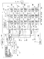
- FIG. 1 is a circuit diagram of a secondary battery deterioration determination device according to a first embodiment of the present invention.
- FIG. It is a block diagram which shows the conceptual structure of the voltage sensor and controller in the degradation determination apparatus of the same secondary battery. It is a flowchart which shows the operation example of the deterioration determination apparatus of the secondary battery. It is a circuit diagram of the deterioration determination apparatus of the secondary battery which concerns on other embodiment of this invention. It is a circuit diagram of the deterioration determination apparatus of the secondary battery which concerns on further another embodiment of this invention. It is a circuit diagram of the deterioration determination apparatus of the secondary battery which concerns on further another embodiment of this invention. It is a circuit diagram of the deterioration determination apparatus of the secondary battery which concerns on further another embodiment of this invention. It is a circuit diagram of the deterioration determination apparatus of the secondary battery which concerns on further another embodiment of this invention. It is a circuit diagram of the deterioration determination apparatus of the secondary battery which concerns on further another embodiment of this invention.
- a power source 1 subject to deterioration determination is an emergency power source in a data center, a mobile phone base station, or other various power sources that require stable power supply.
- the power source 1 has a plurality of battery groups 3 in which a plurality of batteries 2 as secondary batteries are connected in series, and these battery groups 3 are connected in parallel and connected to a load 4.
- Each battery 2 may be a single cell or a battery in which a plurality of cells are connected in series.
- the emergency power source 1 is connected to the positive terminal 5A through the charging circuit 6 and the diode 15 among the positive and negative terminals 5A and 5B of the main power source 5 connected to the positive and negative terminals of the load 4.
- the negative terminal 5B is directly connected.
- the diode 15 is connected in parallel with the charging circuit 6 in such a direction that current flows from the emergency power source 1 to the load 4.
- the main power source 5 is composed of, for example, a DC power source that is connected to an AC commercial power source via a rectifier circuit and a smoothing circuit (both not shown) and converts to DC power.
- the positive potential of the emergency power source 1 is lower than the positive potential of the main power source 5 and normally does not flow to the load 4. However, when the main power source 5 stops or the function is lowered, the potential on the main power source 5 side decreases. Then, the electric charge stored in the emergency power supply 1 is fed to the load 4 via the diode 15. In addition, the charge form which connected the charging circuit 6 as mentioned above is called a trickle charge form.
- This deterioration determination device for a secondary battery is a device for determining the deterioration of each battery 2 in such a power source 1.
- the secondary battery deterioration determination device includes a plurality of voltage sensors 7 individually connected to each battery 2, a plurality of current sensors 8 connected to each battery group 3, and a measurement current including an AC component.
- a controller 11 that receives the measurement value transmitted by 10, calculates the internal resistance of each battery 2 using the received measurement value, and determines the deterioration of the battery 2 from the internal resistance.
- the discharge circuit 9 comprises a series circuit of a current limiting resistor 26 and a switching element 27 and is connected in parallel with the battery group 3.
- the switching element 27 is a semiconductor element such as a thyristor or a transistor.
- a bypass diode 28 is connected to the switching element 27 in parallel.
- the switching element 27 is driven to open and close by a discharge control means 11e in a main controller 11A of the controller 11 to be described later so that the current flowing through the discharge circuit 9 becomes a pulse or sine wave current.
- the discharge control means 11e may be constituted only by hardware, or may be constituted by a CPU or a microcomputer constituting the main controller 11A.
- the voltage sensor 7 is a sensor that detects an AC component and a DC component of the voltage, and includes a sensor function unit 7a and an arithmetic processing unit 7b as shown in FIG.
- the sensor function unit 7a includes a voltage detection element and the like.
- the arithmetic processing unit 7b includes a control unit 7ba that executes a given command, a delay unit 7bb that delays the start of measurement by the sensor function unit 7a with respect to the command by a predetermined time, and the sensor function unit 7a.
- a conversion unit 7bc for converting the detected analog value of the detected AC voltage into an effective value or an average value by a digital signal is provided.
- the voltage sensor 7 has a DC detection unit 7c for detecting a DC voltage, and the detected value of the DC component detected by the DC detection unit 7c is also transmitted from the sensor-by-sensor wireless communication means 10.
- the DC detection unit 7c may also serve as the sensor function unit 7a.
- each voltage sensor 7 has a transmission order set in advance as a transmission delay time by the delay unit 7bb or by other means, and the measurement value is transmitted from each voltage sensor 7 in a time multiplexed manner. The transmission is sequentially performed after the transmission delay time in the set order.
- a temperature sensor 18 for measuring the ambient temperature of the battery 2 and the temperature of the battery is provided, and at least the voltage sensor 7 and the temperature sensor 18 constitute a sensor unit 17.
- the temperature detected by the temperature sensor 18 is transmitted to the controller 11 by the sensor-based wireless communication means 10 together with the voltage measurement value based on the effective value or the average value of the voltage sensor 7.
- the controller 11 is formed by connecting a data server 13 and a monitor 14 to the main controller 11A via the communication network 12.
- the communication network 12 is composed of a LAN and has a hub 12a.
- the communication network 12 may be a wide area communication network.
- the data server 13 can communicate with a remote personal computer (not shown) or the like via the communication network 12 or another communication network, and can monitor data from anywhere.
- the main controller 11A includes a receiving unit 11a that receives the detection value of the voltage sensor 7 transmitted from each sensor wireless communication unit 10, and a transfer unit 11b that transfers the measurement value received by the receiving unit 11a to the communication network 12.
- Each voltage sensor 7 includes a command transmission unit 11c that wirelessly transmits a command such as a transmission start to the sensor-by-sensor wireless communication unit 10, a standby unit 11d described later, and a discharge control unit 11e.
- the discharge control means 11e controls opening and closing of the switching element 27 so that a pulse current or a pseudo sinusoidal discharge current is generated in the discharge circuit 9 (FIG. 1). For example, it is turned on and off at regular intervals.
- wireless transmission / reception of the command transmission unit 11 c and the reception unit 11 a is performed via the antenna 19.
- each current sensor 8 is connected to the main controller 11A by wiring, and the measured value of the current is transferred together with the measured voltage value from the transfer unit 11b of FIG.
- the command transmission unit 11c of the main controller 11A may generate a command by itself, but in this embodiment, in response to a measurement start command transmitted from the data server 13, each sensor of each voltage sensor 7 is wireless.
- the measurement start command is transferred to the communication means 10.
- the main controller 11A or the current sensor 8 is provided with a conversion unit (not shown) that converts the measured value of the current sensor 8 into an effective value or an average value.
- the controller 11 has a function of transmitting the command to the wireless communication unit 10 for each sensor.
- the wireless communication unit 10 for each sensor receives the command, the calculation provided in the voltage sensor 7 is performed. It has a function of giving a command corresponding to this command to the processing unit 7b.
- the data server 13 includes an internal resistance calculation unit 13a and a determination unit 13b.
- the internal resistance calculation unit 13a receives the AC voltage value (execution value or average value), DC voltage value (cell voltage), detected temperature, and current value (execution value or average value) transmitted from the main controller 11A. And the internal resistance of the battery 2 is calculated according to a predetermined calculation formula. The detected temperature is used for temperature correction.
- the determination unit 13b determines that the threshold is set and the calculated internal resistance is greater than or equal to the threshold.
- the threshold value is provided in a plurality of, for example, two to three stages, performs deterioration determination in a plurality of stages, and outputs an alarm corresponding to the plurality of stages as will be described later.
- the determination unit 13b has a function of displaying the determination result on the monitor 14 via the communication network 12 or via a dedicated wiring.
- the data server 13 includes a command transmission unit 13c that transmits a measurement start command to the main controller 11A, and a data storage unit 13d that stores data such as a voltage measurement value transmitted from the main controller 11A. Yes.
- the main controller 11A and the discharge circuit 9 may be configured as an integrated controller in the same case.
- the controller 11 is configured by the main controller 11A and the data server 13 in this embodiment, but the main controller 11A and the data server 13 may be configured as one controller 11 in the same case.
- one information processing apparatus configured by one substrate or the like may be configured without distinction between the main controller 11A and the data server 13.
- the current sensor 8 is provided for each battery group 3, but the current sensor 8 is one in the entire degradation determination device, for example, between the parallel circuit of the battery group 3 and the charging circuit 6. It may be interposed. In each of the following embodiments, one current sensor 8 may be provided.
- the deterioration determination device having the above configuration.
- an alternating current component is applied to the battery 2 and the voltage of the alternating current component is measured by the voltage sensor 7.
- the internal resistance of each battery 2 is calculated using this measured value, and the deterioration of the battery 2 is determined from the internal resistance. For this reason, it is possible to accurately determine deterioration.
- the internal resistance of the battery 2 is closely related to the capacity of the battery 2, that is, the degree of deterioration. If the internal resistance is known, the deterioration of the battery 2 can be accurately determined.
- each battery 2 is determined instead of the entire power source 1 to be subjected to deterioration determination, but a measurement current including an AC component is generated, and the internal resistance of the battery 2 is measured to determine deterioration. Therefore, it is possible to measure with a relatively simple configuration.
- a measurement current is generated by discharging the battery. That is, the switching element 27 is driven to open and close by the discharge control means 11e so as to obtain a pulsed or sinusoidal current. Therefore, there is no need for a power supply device that generates a measurement current from a commercial power supply, and the means for applying the measurement current can be a simple and compact configuration with the discharge circuit 9 including the current limiting resistor 26 and the switching element 27. .
- the deterioration of each battery 2 can be accurately determined, and both the means for performing detection from voltage detection to the determination and the means for applying the measurement current are simple, and are simple and inexpensive as a whole. It becomes the deterioration determination apparatus of the secondary battery which can be manufactured easily.
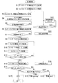
- FIG. 3 is a flowchart of an example of a specific operation of the deterioration determination device.
- the data server 13 transmits a measurement start command from the command transmitter 13c (step S1).
- the main controller 11A receives a measurement start command from the data server 13 (step S2), and transmits a measurement start command to each sensor wireless communication means 10 of each voltage sensor 7 and each current sensor 8 (step S3).
- the standby unit 11d determines the end of the standby time (step S20) and counts the standby time (step S22). When the set standby time ends, the discharge circuit 9 is operated (step S21).
- the measurement start command transmitted in step S3 is received by all the voltage sensors 7 (step S4).
- Each voltage sensor 7 waits for the end of its own measurement delay time (step S5), and then the DC voltage of the battery 2 is received. (Inter-terminal voltage) is measured (step S6). Thereafter, the voltage sensor 7 waits for the end of the standby time (step S7), and measures the AC voltage of the battery 2 (step S8).
- the direct measurement value is converted into an effective voltage or an average voltage, and the converted value is output as a measurement value.
- the measured DC voltage and AC voltage wait for their own transmission delay time and are transmitted wirelessly by the wireless communication means 10 for each sensor (step S9), and the main controller 11A of the controller 11 receives wirelessly (step S10).
- the main controller 11A transmits the received DC voltage and AC voltage together with the detection values of the current sensor 8 and the temperature sensor 18 (FIG. 2) to the data server 13 via the communication network 12 such as a LAN (step S11).
- the data server 13 receives the data of the sensors such as the voltage sensors 7 transmitted in order and stores them in the data storage unit 13d (step S12). From the wireless transmission step S9 to the data storage by the data server 13 is performed until the reception and storage of the data of all the voltage sensors 7 is completed (NO in step S12).
- the discharge circuit 9 is stopped by transmitting the end signal from the data server 13 to the main controller 11A and outputting the current application control signal of the main controller 11A.
- the data server 13 calculates the internal resistance of each battery 2 by the internal resistance calculator 13a (Step S13).
- the determination unit 13b of the data server 13 compares the calculated internal resistance with an appropriately determined first threshold value (step S14), and the battery 2 is normal if it is smaller than the first threshold value. Is determined (step S15). If it is not smaller than the first threshold value, it is further compared with the second threshold value (step S17), and if it is smaller than the second threshold value, an alarm warning for alerting is output (step S18). If it is not smaller than the second threshold value, an alarm that is stronger than the warning is output (step S19). The alarm and warning are displayed on the monitor 14 (FIG. 1). If the above is normal, the monitor 14 may indicate that it is normal, or may not be displayed in particular.
- the alarm and warning display by the monitor 14 may be performed by, for example, a mark such as a predetermined icon or by lighting a predetermined part. In this way, the deterioration determination of all the batteries 2 of the emergency power source 1 is performed.
- FIG. 3 is an example of two-stage deterioration determination (and display of an alarm or the like).
- each voltage sensor 7 is provided for each battery 2 and receives and transfers data with a digital signal by wireless communication. Even in the case of the emergency power source 1 provided with the batteries 2, it is not necessary to worry about the reference potential (ground level) electrically for each battery 2. Therefore, there is no need for differential operation or an isolation transformer. Further, since the measurement values of the plurality of individual voltage sensors 7 are transmitted wirelessly, there is no need for complicated wiring. By these, it can be set as a simple and cheap structure.
- the amount of transmission data is drastically larger than when a voltage waveform signal is transmitted. Less is enough.
- Calculation of the internal resistance of the battery 2 can be performed with an effective value or an average value with high accuracy.
- the calculation of the internal resistance of the battery 2 is possible only by measuring the voltage, it is possible to assume that the current is a constant value. However, the current actually flowing through the battery 2 is measured and the voltage and current are calculated. By obtaining both, the internal resistance can be calculated with higher accuracy. Since the currents flowing through the batteries 2 arranged in series are the same, it is sufficient to provide one current sensor 8 for each battery group 3.
- the controller 11 transmits a measurement start command to each sensor wireless communication means 10 of each voltage sensor 7 and starts measurement of the voltage sensor 2 by this command. Can be arranged. In this case, the controller 11 simultaneously transmits a measurement start command to each voltage sensor 7 by serial transmission or parallel transmission, and each voltage sensor 7 performs measurement simultaneously after the measurement start delay time elapses. After the measurement is completed, the controller 11 sequentially transmits a data transmission request command to each of the voltage sensors 7, and the voltage sensor 7 that has received the command transmits data, and repeats the above to perform data communication. Good. In the present invention, the controller 11 may make a re-transmission request to the voltage sensor 7 that has not been able to receive data after a predetermined time from the transmission of the data transmission request command.
- the measurement of the voltage sensor 7 can be performed in order so as not to hinder wireless transmission and reception, and can be transmitted.
- the transmission start command is a global command, and the voltage sensor 7 acquires it simultaneously.
- the controller 11 makes a re-transmission request to the voltage sensor 7 that has not received data after a predetermined time from the transmission of the measurement start command.
- the measurement start command cannot be received by the sensor-by-sensor wireless communication means 10 of some voltage sensors 7 due to some temporary transmission failure or the like. Even in such a case, by performing the re-transmission request, the voltage can be measured and transmitted, and the voltage measurement values of all the batteries 2 of the power source can be obtained. Whether or not the measurement start command has been received may be determined by determining whether or not the voltage measurement value has been received on the controller 11 side.
- the controller 11 may individually transmit a data request command to the wireless communication means 10 for each sensor of each voltage sensor 7 and sequentially receive the data.
- the delay unit 7bb is not required on the voltage sensor 7 side, and the configuration on the voltage sensor 7 side is simplified. Since the controller 11 outputs a multi-stage alarm according to the calculated magnitude of the internal resistance, the urgency of the need for battery replacement can be known, and maintenance planning and preparation can be performed without performing unnecessary battery replacement. Can be done smoothly and quickly.
- the controller 11 or its internal components include a predetermined conversion function stored in a LUT (Look Up Table) implemented by software or hardware, or a software library (Library), or an equivalent thereof.
- a hardware circuit or processor (not shown) that can perform computations and output the results using the library comparison functions, four arithmetic operations functions, or equivalent hardware, etc. It consists of software functions.
- FIG. 4 shows another embodiment of the present invention.
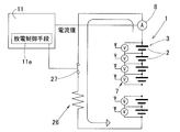
- the emergency power source 1 is composed of one battery group 3 and is a power source that can be used for various purposes without being limited to emergency use, and is not connected to a charging circuit.
- the controller 11 is composed of a single computer or the like, and includes a command transmission unit 11c, a data storage unit 13d, an internal resistance calculation unit 13a, and a determination unit 13b in FIG. Also in this configuration, as in the above embodiment, the deterioration of each battery 2 in the power source 1 to be determined can be accurately determined, and the configuration is simple and can be manufactured at low cost. There is an advantage that the measurement current generation means including a simple and compact configuration is sufficient. Other configurations and effects are the same as those of the first embodiment described above with reference to FIGS.
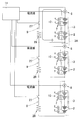
- FIG. 5 to FIG. 8 show still other embodiments.
- other configurations that are particularly described are the same as those in the first embodiment shown in FIGS. 1 to 3, and the effects described in the first embodiment can be obtained.
- a plurality of series connection bodies 3 ⁇ / b> A in which a plurality of battery groups 3 (two in FIG. 5) are connected in series are connected in parallel.
- the connected battery group 3 forms a parallel connection body 3B.
- the discharge circuit 9 is provided for each parallel connection body 3B, and there are two discharge circuits 9 in total.
- the series connection body 3A in the power source 1 is one battery group 3
- the one battery group 3 is divided into a plurality (two) of battery group division bodies 3a arranged in series.
- the battery group divided body 3a is divided and connected in parallel with the battery group divided bodies 3a of other battery groups.
- the discharge circuit 9 is provided in parallel for each parallel connection body 3B of the battery group division body 3a.
- each battery group divided body 3a includes a plurality of the batteries 2 connected in series.
- the voltage of the battery 2 connected in series in the entire power source 1 is a high voltage exceeding 300V, for example.
- the switching element 27 which is a power element for applying a measurement current, needs to have a high withstand voltage.
- the switching element 27 that is a power element for applying a measurement current in the discharge circuit 26 is Those with a low pressure resistance can be used.
- the power source 1 includes a series connection body 3 ⁇ / b> A of two battery groups 3, and is a power source that can be used not only for emergency use but also for various purposes, and is not connected to a charging circuit.
- the controller 11 is composed of a single computer or the like, and although not shown in the figure, the discharge control means 11e in FIG. 1, the command transmission unit 11c, the data storage unit 13d, the internal resistance calculation unit 13a, and the determination unit 13b in FIG. Is provided.
- the series connection body 3 ⁇ / b> A is composed of three or more battery groups 3 connected in series.
- the one battery group 3 is composed of three or more battery group division bodies 3a.
- the discharge circuit 9 is provided in parallel for each parallel connection body 3B, and a total of three or more discharge circuits 9 are included.
- an element having a low withstand voltage can be used as the switching element 27 that is a power element for applying a measurement current.
- the embodiment of FIG. 8 is an example in which the series connection body 3A is configured by three or more battery groups 3 connected in series in the embodiment shown in FIG.
- the series connection body 3A of the batteries 2 of the power source 1 is regarded as one battery group 3
- the one battery group 3 is composed of three or more battery group division bodies 3a.
- the discharge circuit 9 is provided in parallel for each parallel connection body 3B, and three or more discharge circuits 9 are included in total.
- an element having a low withstand voltage can be used as the switching element 27 that is a power element for applying a measurement current.
Landscapes
- Engineering & Computer Science (AREA)
- Manufacturing & Machinery (AREA)
- Chemical & Material Sciences (AREA)
- Chemical Kinetics & Catalysis (AREA)
- Electrochemistry (AREA)
- General Chemical & Material Sciences (AREA)
- Physics & Mathematics (AREA)
- General Physics & Mathematics (AREA)
- Power Engineering (AREA)
- Secondary Cells (AREA)
- Tests Of Electric Status Of Batteries (AREA)
- Charge And Discharge Circuits For Batteries Or The Like (AREA)
Abstract
バッテリの複数が直列接続されたバッテリ群が複数並列に接続された非常用電源における各バッテリの劣化を精度良く判定することができ、かつ簡素で安価に製造可能であり、特に交流成分を含む計測用電流の生成手段が簡素でコンパクトな構成で済む二次電池の劣化判定装置を提供する。各バッテリ(2)に接続された複数の電圧センサ(7)と、バッテリ群(3)と並列に接続された放電回路(9)と、放電制御手段(11e)とを備える。放電制御手段(11e)は、放電回路(9)を流れる電流がパルス状等となるようにスイッチング素子(27)を開閉駆動する。電圧センサ(7)は交流成分の電圧値を計測する。この計測値から内部抵抗演算部が内部抵抗を演算し、内部抵抗から判定部がバッテリ(2)の劣化を判定する。
Description
本出願は、2016年3月18日出願の特願2016-054774の優先権を主張するものであり、その全体を参照により本願の一部をなすものとして引用する。
この発明は、データセンタ、携帯電話基地局、またはその他各種の電力安定供給が求められる電源装置における非常用電源等に用いられる二次電池の劣化を判定する劣化判定装置に関する。
データセンタおよび携帯電話基地局等では、電力の安定供給が重要であり、定常時には交流商用電源が用いられるが、交流商用電源が停止した場合の無停電電源装置として、二次電池を用いた非常用電源が装備される。非常用電源の充電方式としては、充電回路を用いて定常時に微小電流で充電するトリクル充電の形式と、整流器に対して負荷と二次電池を並列に接続し、一定電流を印加して負荷を運転させつつ充電するフロート充電の形式とがある。一般的に非常用電源にはトリクル充電の形式が多く採用されている。
前記非常用電源は、商用電源で駆動される負荷の駆動が可能な電圧と電流が要求され、一つの二次電池(バッテリ)の電圧は低く、また容量も小さいため、複数のバッテリが直列接続されたバッテリ群を複数並列に接続した構成とされる。個々のバッテリは、鉛蓄電池やリチウムイオン電池である。
このような非常用電源において、バッテリは劣化によって電圧が低下するため、信頼性確保のために、バッテリの劣化判定を行い、劣化したバッテリを交換しておくことが望まれる。しかし、データセンタ、携帯電話基地局等の大規模な非常用電源における多数のバッテリを精度良く劣化判定できる装置は、提案されるに至っていない。
従来のバッテリの劣化判定の提案例としては、車載バッテリチェッカーとして、バッテリ全体を纏めて計測する提案(例えば、特許文献1)、バッテリにパルス状電圧を印加し、入力電圧と応答電圧とからバッテリ全体の内部インピーダンスを算出する提案(例えば、特許文献2)、バッテリにおける直列接続された個々のセルの内部抵抗を計測し、劣化判定する方法(例えば、特許文献3)等が提案されている。個々のセルの内部抵抗を計測には交流4端子法が用いられている。また、バッテリの内部抵抗等の非常に小さな抵抗値を計測するハンディチェッカーとして、交流4端子法バッテリテスタが商品化されている(例えば、非特許文献1)。
前記特許文献1,2では、無線によるデータ送信も提案され、ケーブルの取り回しや手作業の削減、コンピュータによるデータ管理も提案されている。
交流4端子法 バッテリーテスタ 内部抵抗計測器 IW7807-BP(Rev.1.7.1、2015年2月16日、東京デバイセズ)(https://tokyodevices.jp/system/attachments/files/000/000/298/original/IW7807-BP-F_MANUAL.pdf)
従来の前記ハンディチェッカー(非特許文献1)は、バッテリが何十、何百と接続された非常用電源では、計測箇所が多くなり過ぎ、実現性がない。特許文献1,2の技術は、いずれも、バッテリからなる電源の全体を計測するものであり、個々のバッテリ、つまり個々のセルの計測を行うものではない。そのため、劣化判定の精度が低く、また劣化した個々のバッテリを特定することができない。
特許文献3の技術は、直列接続された個々のセルの内部抵抗を計測することでは、劣化判定の精度向上、および劣化した個々のバッテリを特定する技術に繋がる。しかし、個々のセルの内部抵抗の計測に交流4端子法が用いられているため、構成が複雑であって、数十ないし数百のセルを持つ大規模な非常用電源では実用化が難しい。
バッテリの劣化を精度良く判定できる比較的に簡易な装置としては、バッテリにリップル電流またはパルス電流などの交流成分を有する電流を印加し、バッテリの端子間電圧の交流成分からバッテリの内部抵抗を計測し、劣化を判定する方法がある。しかし、リップル電流の発生手段につき、構造が簡単で安価に製作できるものが提案されるに至っていない。
この発明の目的は、それぞれ二次電池であるバッテリの複数が直列接続されたバッテリ群が複数並列に接続された電源における前記各バッテリの劣化を精度良く判定することができ、かつ簡素で安価に製造可能であり、特に交流成分を含む計測用電流の生成手段が簡素でコンパクトな構成で済む二次電池の劣化判定装置を提供することである。
以下、この発明について、理解を容易にするために、便宜上実施形態の符号を参照して説明する。
この発明の二次電池の劣化判定装置は、それぞれ二次電池であるバッテリ2の複数が直列接続されたバッテリ群3が複数並列に接続されまたは単独で設けられて負荷に接続される電源1における前記各バッテリ2の劣化を判定する二次電池の劣化判定装置であって、
前記各バッテリ2に個別に接続されこのバッテリに印加された電圧の交流成分の電圧を計測する複数の電圧センサ7と、
前記バッテリ群3と並列に接続された、電流制限用抵抗26とスイッチング素子27の直列回路からなる放電回路9と、
前記放電回路9を流れる電流がパルス状ないし正弦波状の電流となるように前記スイッチング素子27を開閉駆動する放電制御手段11eと、
前記各電圧センサ7の計測値を用いて前記電圧センサ7が設けられた前記バッテリ2の内部抵抗を算出する内部抵抗演算部13aと、
この内部抵抗演算部13aで算出した内部抵抗を用いて前記バッテリ2の劣化を判定する判定部13bとを備える。
電源1は、例えばデータセンタまたは携帯電話基地局に装備される非常用の電源である。
前記各バッテリ2に個別に接続されこのバッテリに印加された電圧の交流成分の電圧を計測する複数の電圧センサ7と、
前記バッテリ群3と並列に接続された、電流制限用抵抗26とスイッチング素子27の直列回路からなる放電回路9と、
前記放電回路9を流れる電流がパルス状ないし正弦波状の電流となるように前記スイッチング素子27を開閉駆動する放電制御手段11eと、
前記各電圧センサ7の計測値を用いて前記電圧センサ7が設けられた前記バッテリ2の内部抵抗を算出する内部抵抗演算部13aと、
この内部抵抗演算部13aで算出した内部抵抗を用いて前記バッテリ2の劣化を判定する判定部13bとを備える。
電源1は、例えばデータセンタまたは携帯電話基地局に装備される非常用の電源である。
なお、この明細書で言う交流成分は、電圧の大きさが繰り返し変化する成分であり、電圧の向きが常に一定であっても良く、例えばリップル電流やパルス電流であっても良い。前記「バッテリ」は、複数のセルが直列接続されたものであっても、セル単独であっても良い。
この構成によると、バッテリ2に交流成分を与えてその交流成分の電圧を電圧センサ7で計測する。この計測値を用いて各バッテリ2の内部抵抗を算出し、内部抵抗から前記バッテリ2の劣化を判定する。このため、精度良く劣化を判定することができる。バッテリ2の内部抵抗は、バッテリ2の容量、つまり劣化の程度と密接な関係があり、内部抵抗が分かれば、バッテリ2の劣化を精度良く判定できる。また、劣化判定対象の電源1の全体ではなく、個々のバッテリ2の劣化を判定するが、交流成分を含む計測用電流を生じさせ、バッテリ2の内部抵抗を計測して劣化判定する構成であるため、比較的に簡易な構成で計測できる。
バッテリ2に交流成分を生じさせる手段が必要であるが、放電によって計測用の電流を生成する。すなわち、スイッチング素子27を、放電制御手段11eによって、放電回路9を流れる電流がパルス状ないし正弦波状の電流となるように開閉駆動する。そのため、商用電源やこの商用電源から計測用電流を作る電源装置が不要であり、計測用電流を生成する手段が、電流制限抵抗26とスイッチング素子27とで構成された放電回路9による簡易でコンパクトな構成ですむ。このように、各バッテリ2の劣化を精度良く判定することができ、電圧等の検出から判定までを行う手段、および計測用電流を生成する手段のいずれもが簡素であり、全体として簡素で安価に製造可能な二次電池の劣化判定装置となる。
この発明において、前記各バッテリ群3毎に電流センサ8が接続され、前記コントローラ11は、前記各電圧センサ7の前記計測値とこの電圧センサ7が設けられた前記バッテリ群3毎の前記電流センサ8の計測値とから前記各バッテリ2の内部抵抗を算出する前記内部抵抗演算部13a、およびこの内部抵抗演算部13aの演算結果から前記各バッテリ2の劣化を判定する判定部13bを有するようにしても良い。電圧の計測だけであっても、電流を一定値に仮定することなどで、内部抵抗の算出が可能ではあるが、バッテリ2に実際に流れる電流を計測し、電圧と電流との両方を求めることで、内部抵抗をより一層精度良く算出することができる。直列に並んだ各バッテリに流れる電流は同じであるため、電流センサ8はバッテリ群3毎に1つ設けられていれば足りる。なお、電流センサ8は1つとし、例えばバッテリ群3の並列回路と充電回路6との間に介在させても良い。
この発明において、前記各電圧センサ7は、計測した電圧値を実効値または平均値に変換する変換部7bcを有し、前記内部抵抗演算部13aは、前記実効値または平均値から前記バッテリ2の内部抵抗を計測する構成であっても良い。このように、各電圧センサ7の計測した前記計測値を、実効値または平均値に変換し、送信するため、電圧波形の信号を送る場合に比べて飛躍的に送信データ量が少なくて済む。バッテリ2の内部抵抗の算出は実効値または平均値で精度良く行える。
この発明において、前記各電圧センサ7毎に、この電圧センサの計測値を無線で送信するセンサ毎無線通信手段10を備えるようにしても良い。無線通信によりデータの受け取り受け渡しをする構成であると、数十から数百個のバッテリ2を備える非常用の電源1であっても、各バッテリ2につき、電気的に基準電位(グランドレベル)を気にする必要がない。そのため、差動演算や絶縁トランスの必要がない。また、複数ある個々の電圧センサ7の計測値を無線で送信するため、複雑な配線の必要がない。これらにより、簡単で安価な構成とできる。
この発明の二次電池の劣化判定装置において、前記バッテリ群3が複数直列に接続されて直列接続体3Aをなし、この直列接続体3Aが複数並列に接続され、複数の前記直列接続体3Aの間で、互いに対応する個々の前記バッテリ群3の間の部位aが相互に接続されており、複数の前記直列接続体3A間で、互いに並列接続されているバッテリ群3どうしで並列接続体3Bを成し、この一つの並列接続体毎3Bに前記放電回路9が設けられていても良い。
換言すれば、前記電源1における前記直列接続体3Aが一つのバッテリ群3であると見做すと、この一つのバッテリ群3が、直列方向に並ぶ複数のバッテリ群分割体3aに分割され、このバッテリ群分割体3aが他のバッテリ群のバッテリ群分割体3aと並列に接続され、このバッテリ群分割体3aの並列接続体3B毎に並列に前記放電回路9が設けられた構成と言える。ただし、前記バッテリ群分割体3aは、前記バッテリ2が複数直列に接続されている。
前記電源1がデータセンタの非常用電源等である場合、電源1の全体におけるバッテリの各直列接続体の電圧は、例えば300Vを超える高い電圧となる。このため、前記電源1の全体に対して放電回路26を設けると、測定電流を印加するためのパワー素子である前記スイッチング素子27に耐圧が高いものが必要である。しかし、上記のようにバッテリ2の直列接続体を直列方向に複数に分割された構成とすることで、前記放電回路26における測定電流印加用のパワー素子である前記スイッチング素子27に、耐圧の低いものが使用できる。
請求の範囲および/または明細書および/または図面に開示された少なくとも2つの構成のどのような組合せも、この発明に含まれる。特に、請求の範囲の各請求項の2つ以上のどのような組合せも、この発明に含まれる。
この発明は、添付の図面を参考にした以下の好適な実施形態の説明から、より明瞭に理解されるであろう。しかしながら、実施形態および図面は単なる図示および説明のためのものであり、この発明の範囲を定めるために利用されるべきものではない。この発明の範囲は添付の請求の範囲によって定まる。添付図面において、複数の図面における同一の符号は、同一または相当する部分を示す。
この発明の二次電池の劣化判定装置の第1の実施形態を、図1ないし図3と共に説明する。図1において、劣化判定対象の電源1は、データセンタ、携帯電話基地局、またはその他各種の電力安定供給が求められる電源装置における非常用電源である。この電源1は、それぞれ二次電池であるバッテリ2の複数が直列接続されたバッテリ群3を複数有し、これらバッテリ群3が並列に接続され負荷4に接続される。各バッテリ2は、一つのセルであっても、また複数のセルが直列接続されたバッテリであっても良い。
この非常用の電源1は、負荷4の正負の端子に接続された主電源5の正負の端子5A,5Bのうち、正の端子5Aには充電回路6とダイオード15とを介して接続され、負の端子5Bには直接に接続されている。ダイオード15は非常用の電源1から負荷4に電流を流す向きで、充電回路6と並列に接続されている。主電源5は、例えば交流商用電源に整流回路および平滑回路(いずれも図示せず)介して接続されて直流電力に変換する直流電源等からなる。
非常用の電源1の正電位は、主電源5の正電位よりも低く、通常は負荷4には流れないが、主電源5が停止または機能低下すると、主電源5側の電位が低下することから、非常用の電源1に蓄電した電荷により、ダイオード15を介して負荷4に給電される。なお、上記のように充電回路6を接続した充電形式は、トリクル充電形式と呼ばれる。
この二次電池の劣化判定装置は、このような電源1における各バッテリ2の劣化を判定する装置である。この二次電池の劣化判定装置は、前記各バッテリ2に個別に接続された複数の電圧センサ7と、各バッテリ群3に接続された複数の電流センサ8と、交流成分を含む計測用電流を前記バッテリ群3に印加する放電回路9と、各電圧センサ7に設けられ計測された交流成分の電圧の計測値を無線で送信するセンサ毎無線通信手段10と、前記各電圧センサ毎無線通信手段10の送信した前記計測値を受信し、この受信した計測値を用いて各バッテリ2の内部抵抗を算出し、内部抵抗から前記バッテリ2の劣化を判定するコントローラ11とを備える。
前記放電回路9は、電流制限用抵抗26とスイッチング素子27の直列回路からなり、前記バッテリ群3と並列に接続されている。スイッチング素子27は、サイリスタやトランジスタ等の半導体素子である。スイッチング素子27にはバイパス用のダイオード28が並列に接続されている。スイッチング素子27は、後述のコントローラ11の主コントローラ11Aにおける放電制御手段11eによって、放電回路9を流れる電流がパルス状ないし正弦波状の電流となるように開閉駆動される。放電制御手段11eは、ハードウェアのみで構成されていても、主コントローラ11Aを構成するCPUやマイクロコンピュータで構成されていても良い。
電圧センサ7は、電圧の交流成分と直流成分の検出を行うセンサであり、図2に示すように、センサ機能部7aと演算処理部7bとを有する。センサ機能部7aは、電圧検出素子等からなる。演算処理部7bは、与えられたコマンドを実行する制御部7baと、コマンドに対してセンサ機能部7aの計測の開始を、定められた時間だけ遅延させる遅延部7bbと、前記センサ機能部7aで検出した交流電圧のアナログの検出値を、ディジタル信号による実効値または平均値に変換する変換部7bcとが設けられている。電圧センサ7は、この他に直流電圧を検出する直流検出部7cを有し、直流検出部7cで検出した直流成分の検出値も、前記センサ毎無線通信手段10から送信される。なお、直流検出部7cはセンサ機能部7aが兼ねるようにしても良い。また、各電圧センサ7は、前記遅延部7bbにより、または他の手段により、予め送信順が送信遅延時間で設定されており、計測値を、各電圧センサ7から時間多重で送信されるように、設定された順に送信遅延時間後に順次送信する。
また、この実施形態では、バッテリ2の周囲の温度やバッテリの温度を計測する温度センサ18が設けられ、少なくとも電圧センサ7と、温度センサ18とでセンサユニット17を構成している。温度センサ18の検出温度は、電圧センサ7の前記実効値または平均値による電圧計測値と共に、センサ毎無線通信手段10でコントローラ11へ送信される。
前記コントローラ11は、この実施形態では主コントローラ11Aに、通信網12を介してデータサーバ13およびモニタ14を接続してなる。通信網12は、この実施形態ではLANからなり、ハブ12aを有している。通信網12は広域通信網であっても良い。データサーバ13は、前記通信網12や他の通信網により、遠隔地のパーソナルコンピュータ(図示せず)等と通信可能であり、どこからでもデータ監視できる。
主コントローラ11Aは、各センサ毎無線通信手段10から送信された電圧センサ7の検出値を受信する受信部11aと、受信部11aで受信した計測値を通信網12へ転送する転送部11bと、各電圧センサ7のセンサ毎無線通信手段10に無線で送信開始等のコマンドを送信するコマンド送信部11cと、後述の待機部11dと、放電制御手段11eとを有している。放電制御手段11eは、放電回路9(図1)にパルス電流ないし擬似的な正弦波状の放電電流を生じさせるように、スイッチング素子27を開閉制御する。たとえば、一定周期でオンオフさせる。図2において、コマンド送信部11cおよび受信部11aの無線送受は、アンテナ19を介して行われる。
図1に示すように、各電流センサ8は、主コントローラ11Aに配線で接続され、その電流の計測値は図2の前記転送部11bから電圧計測値と共に転送される。前記主コントローラ11Aの前記コマンド送信部11cは、自己でコマンドを生成しても良いが、この実施形態では、データサーバ13から送信された計測開始コマンドに応答して各電圧センサ7のセンサ毎無線通信手段10へ前記計測開始コマンドを転送する。なお、主コントローラ11Aまたは電流センサ8に、この電流センサ8の計測値を実効値または平均値に換算する換算部(図示せず)が設けられている。
上記のように、コントローラ11は、各センサ毎無線通信手段10に前記コマンドを送信する機能を有し、各センサ毎無線通信手段10は、当該コマンドを受信すると、電圧センサ7に備えられた演算処理部7bにこのコマンドに対応する指令を与える機能を有している。
データサーバ13は、内部抵抗演算部13aと判定部13bとを有する。内部抵抗演算部13aは、主コントローラ11Aから送信されて受信した交流電圧値(実行値または平均値)と、直流電圧値(セル電圧)と、検出温度と、電流値(実行値または平均値)とを用い、定められた計算式に従ってバッテリ2の内部抵抗を算出する。検出温度は、温度補正に用いられる。
判定部13bは、閾値が設定され、算出された内部抵抗が閾値以上であると劣化と判定する。前記閾値は、複数、例えば2~3段階に設けられ、複数段階の劣化判定を行い、後述のようにこの複数段階に対応した警報を出力する。判定部13bは、判定結果を、前記通信網12を介して、または専用の配線を介してモニタ14に表示させる機能を有する。データサーバ13は、この他に、主コントローラ11Aへ計測開始コマンドを送信するコマンド送信部13cと、主コントローラ11Aから送信された電圧計測値などのデータを格納するデータ格納部13dとを有している。
なお、上記構成において、主コントローラ11Aと放電回路9とは、同一ケースに入れた一体のコントローラとして構成されても良い。また、コントローラ11は、この実施形態では主コントローラ11Aとデータサーバ13とで構成したが、これら主コントローラ11Aとデータサーバ13とは、同一ケースに入った一つのコントローラ11として構成しても良く、また一つの基板等で構成される一つの情報処理装置に、主コントローラ11Aとデータサーバ13との区別なく構成されていても良い。また、この実施形態ではバッテリ群3毎に電流センサ8を設けているが、電流センサ8はこの劣化判定装置の全体で1つとし、例えばバッテリ群3の並列回路と充電回路6との間に介在させても良い。以下の各実施形態においても電流センサ8を一つとしても良い。
上記構成の劣化判定装置の動作を説明する。この構成によると、バッテリ2に交流成分を与えてその交流成分の電圧を電圧センサ7で計測する。この計測値を用いて各バッテリ2の内部抵抗を算出し、内部抵抗から前記バッテリ2の劣化を判定する。このため、精度良く劣化を判定することができる。バッテリ2の内部抵抗は、バッテリ2の容量、つまり劣化の程度と密接な関係があり、内部抵抗が分かれば、バッテリ2の劣化を精度良く判定できる。また、劣化判定対象の電源1の全体ではなく、個々のバッテリ2の劣化を判定するが、交流成分を含む計測用電流を生じさせ、バッテリ2の内部抵抗を計測して劣化判定する構成であるため、比較的に簡易な構成で計測できる。
バッテリ2に交流成分を生じさせる手段が必要であるが、バッテリの放電によって計測用の電流を生成する。すなわち、スイッチング素子27を放電制御手段11eによって、パルス状ないし正弦波状の電流となるように開閉駆動する。そのため、商用電源から計測用電流を作る電源装置が不要であり、計測用電流を印加する手段が、電流制限抵抗26とスイッチング素子27とで構成された放電回路9による簡易でコンパクトな構成ですむ。このように、各バッテリ2の劣化を精度良く判定することができ、電圧等の検出から判定までを行う手段、および計測用電流を印加する手段のいずれもが簡素であり、全体として簡素で安価に製造可能な二次電池の劣化判定装置となる。
図3は、この劣化判定装置の具体的な動作の一例の流れ図である。データサーバ13は、コマンド送信部13cから計測開始コマンドを送信する(ステップS1)。主コントローラ11Aは、データサーバ13から計測開始コマンド受信し(ステップS2)、各電圧センサ7のセンサ毎無線通信手段10、および各電流センサ8へ計測開始コマンドを送信する(ステップS3)。この送信以降の処理と並行して、待機部11dにより待機時間の終了判定(ステップS20)および待機時間のカウント(ステップS22)を行う。設定された待機時間が終了すると、放電回路9を動作させる(ステップS21)。
ステップS3で送信された計測開始コマンドは、全数の電圧センサ7が受信し(ステップS4)、各電圧センサ7は、自己の計測遅延時間の終了を待って(ステップS5)、バッテリ2のDC電圧(端子間電圧)を計測する(ステップS6)。この後、電圧センサ7は、待機時間の終了を待って(ステップS7)、バッテリ2のAC電圧を計測する(ステップS8)。AC電圧の計測については、直接の計測値を実効電圧または平均電圧に換算し、その換算値を計測値として出力する。
計測したDC電圧およびAC電圧は、自己の送信遅延時間だけ待って、センサ毎無線通信手段10により無線で送信し(ステップS9)、コントローラ11の主コントローラ11Aが無線で受信する(ステップS10)。主コントローラ11Aは、受信したDC電圧およびAC電圧を、電流センサ8および温度センサ18(図2)の検出値と共に、データサーバ13へLAN等の通信網12で送信する(ステップS11)。データサーバ13は、順に送信される各電圧センサ7等のセンサのデータを受信してデータ格納部13dに格納する(ステップS12)。前記無線送信のステップS9からデータサーバ13によるデータ格納までは、全電圧センサ7のデータの受信および格納が終了するまで行う(ステップS12でNO)。
この受信および格納の終了(ステップS12でYES)の後、その終了信号のデータサーバ13から主コントローラ11Aへの送信、および主コントローラ11Aの電流印加制御信号の出力によって、前記放電回路9を停止させ(ステップS16)、データサーバ13では内部抵抗演算部13aで各バッテリ2の内部抵抗を演算する(ステップS13)。
データサーバ13の判定部13bは、演算された内部抵抗を、適宜定められた第1しきい値と比較し(ステップS14)、第1しきい値よりも小さい場合は、バッテリ2が正常であると判定する(ステップS15)。第1しきい値よりも小さくない場合は、さらに第2しきい値と比較し(ステップS17)、第2しきい値より小さい場合、注意を喚起する警報の警告を出力する(ステップS18)。第2しきい値よりも小さくない場合は、警告よりも強い知らせの警報を出力する(ステップS19)。前記警報および警告は、モニタ14(図1)で表示する。上記の正常な場合は、モニタ14に正常である旨を表示しても良く、また特に表示しなくても良い。前記モニタ14による警報および警告の表示は、例えば定められたアイコン等のマークにより行っても、所定部位の点灯等で行っても良い。このようにして、非常用の電源1の全てのバッテリ2の劣化判定を行う。なお、図3は、2段階の劣化判定(および警報等の表示)の例である。
この二次電池の劣化判定装置によると、このように、各電圧センサ7は、バッテリ2毎に設けられ、無線通信によりディジタル信号でデータの受け取り、受け渡しをするため、数十から数百個のバッテリ2を備える非常用の電源1であっても、各バッテリ2につき、電気的に基準電位(グランドレベル)を気にする必要がない。そのため、差動演算や絶縁トランスの必要がない。また、こうした複数ある個々の電圧センサ7の計測値を無線で送信するため、複雑な配線の必要がない。これらにより、簡単で安価な構成とできる。
また、各電圧センサ7の計測した前記計測値を、ディジタル信号で表される実効値または平均値に変換し、送信するため、電圧波形の信号を送る場合に比べて飛躍的に送信データ量が少なくて済む。バッテリ2の内部抵抗の算出は実効値または平均値で精度良く行える。バッテリ2の内部抵抗の算出については、電圧の計測だけであっても、電流を一定値に仮定することなどで可能ではあるが、バッテリ2に実際に流れる電流を計測し、電圧と電流との両方を求めることで、内部抵抗をより一層精度良く算出することができる。直列に並んだ各バッテリ2に流れ電流は同じであるため、電流センサ8はバッテリ群3毎に1つ設ければ足りる。
前記コントローラ11は、前記各電圧センサ7の各センサ毎無線通信手段10に計測開始コマンドを送信し、このコマンドによって電圧センサ2の計測を開始させるため、多数存在する各電圧センサ2の計測開始タイミングを整えることができる。この場合に、前記コントローラ11は、前記各電圧センサ7に計測開始コマンドを同時にシリアル伝送またはパラレル伝送で送信し、各電圧センサ7は、計測開始遅延時間経過後に同時に計測を行う。計測終了後、前記コントローラ11は、順に前記各電圧センサ7にデータ送信の要求コマンドを送信し、コマンドを受けた電圧センサ7がデータを送信し、以上を繰り返すことで、データ通信を行ってもよい。この発明において、前記コントローラ11は、データ送信要求コマンドの送信から一定時間後に、データ受信できなかった前記電圧センサ7に対し再送信要求を行うようにして良い。
別の例として、各電圧センサ7毎に定められた計測開始遅延時間だけ経過後に計測を行うようにする場合、各センサ毎無線通信手段10へ同時に計測開始コマンドを送信しても、多数ある各電圧センサ7の計測を、無線送受に支障がないように順に行い、送信することかできる。例えば、送信開始コマンドはグローバルコマンドであり、電圧センサ7は同時に取得する。
前記コントローラ11は、前記計測開始コマンドの送信から一定時間後に、データ受信できなかった前記電圧センサ7に対し再送信要求を行う。何らかの一時的な送信の障害等により、一部の電圧センサ7のセンサ毎無線通信手段10で計測開始コマンドを受信できない場合がある。そのような場合でも、前記再送信要求を行うことで、電圧を計測して送信でき、電源の全てのバッテリ2の電圧計測値を得ることができる。計測開始コマンドを受信できたか否かは、コントローラ11側で、電圧の計測値が受信されたか否かを判断することで行えば良い。
コントローラ11は、前記のように計測開始コマンドを同時に送信するのではなく前記各電圧センサ7のセンサ毎無線通信手段10に個別にデータ要求コマンドを送信し、順にデータを受信するようにしても良い。この構成の場合、電圧センサ7側に遅延部7bbが不要となり、電圧センサ7側の構成が簡素化される。前記コントローラ11は、算出した前記内部抵抗の大きさに応じて複数段階の警報を出力するため、バッテリ交換の必要性の緊急度がわかり、無駄なバッテリ交換を行うことなく、保守の計画や準備が円滑かつ迅速に行える。
コントローラ11またはその内部の構成要素は、具体的には、ソフトウエアやハードウエアで実現されたLUT(Look Up Table)、またはソフトウエアのライブラリ(Library)に収められた所定の変換関数やそれに等価のハードウエア等、また必要に応じて、ライブラリの比較関数や四則演算関数やそれらに等価のハードウエア等を用いて、演算を行って結果を出力しうるハードウエア回路またはプロセッサ(不図示)上のソフトウエア関数で構成されている。
図4は、この発明の他の実施形態を示す。この例では、非常用の電源1は、一つのバッテリ群3からなり、非常用に限らず種々の用途に使用可能な電源であり、充電回路とは接続されていない。コントローラ11は単独のコンピュータ等からなり、放電制御手段11eの他に、図示は省略するが、図2のコマンド送信部11c、データ格納部13d、内部抵抗演算部13a、判定部13bを備える。この構成の場合も、上記実施形態と同様に、判定対象の電源1における前記各バッテリ2の劣化を精度良く判定することができ、かつ構成が簡素で安価に製造することができ、特に交流成分を含む計測用電流の生成手段が簡素でコンパクトな構成で済むと言う利点が得られる。その他の構成、効果は、図1~3と共に前述した第1の実施形態と同様である。
図5~図8は、それぞれさらに他の実施形態を示す。これらの実施形態において、特に説明した事項の他の構成は、図1~図3に示した第1の実施形態と同様であり、また第1の実施形態につき説明した各効果が得られる。
図5において、電源1では、バッテリ群3が複数(図5では2つ)直列に接続された直列接続体3Aが複数並列に接続されている。複数の直列接続体3Aの間で、互いに対応する個々の前記バッテリ群3の間の部位aは相互に接続されていて(接続線は1本)、複数の直列接続体3A間で、互いに並列接続されているバッテリ群3どうしで並列接続体3Bを成す。この一つの並列接続体3B毎に前記放電回路9が設けられ、全部で放電回路9は2つ存在している。
換言すれば、前記電源1における直列接続体3Aが一つのバッテリ群3であると見做すと、この一つのバッテリ群3が、直列方向に並ぶ複数(2つ)のバッテリ群分割体3aに分割され、このバッテリ群分割体3aが他のバッテリ群のバッテリ群分割体3aと並列に接続されている。このバッテリ群分割体3aの並列接続体3B毎に並列に前記放電回路9が設けられた構成である。分割数は問わないが、個々のバッテリ群分割体3aは、前記バッテリ2が複数直列に接続されている。
前記電源1がデータセンタの非常用電源等である場合、電源1の全体におけるバッテリ2の直列接続体の電圧は、例えば300Vを超える高い電圧となる。このため、前記電源1の全体に対して放電回路26を設けると、測定電流を印加するためのパワー素子である前記スイッチング素子27に耐圧が高いものが必要である。しかし、この実施形態のようにバッテリ2の直列接続体を直列方向に二つに分割された構成とすることで、前記放電回路26における測定電流印加用のパワー素子である前記スイッチング素子27に、耐圧の低いものが使用できる。
図6の実施形態では、電源1は、二つのバッテリ群3の直列接続体3Aからなり、非常用に限らず種々の用途に使用可能な電源であり、充電回路とは接続されていない。コントローラ11は単独のコンピュータ等からなり、同図における図示は省略するが、図1の放電制御手段11eおよび、図2のコマンド送信部11c、データ格納部13d、内部抵抗演算部13a、判定部13bを備える。
図7の実施形態は、図5に示す実施形態において、直列接続体3Aを、直列接続させた3つ以上のバッテリ群3で構成した例である。換言すれば、電源1のバッテリ2の直列接続体3Aを一つのバッテリ群3と見做した場合に、この一つのバッテリ群3が3つ以上のバッテリ群分割体3aで構成されている。複数の直列接続体3Aの間で、互いに対応する個々の前記バッテリ群3の間の部位a(直列接続体3A中に複数存在)は相互に接続されていて(接続線は2本以上となる)、並列接続体3B毎に並列に前記放電回路9が設けられ、全部で放電回路9が3つ以上含まれる構成である。この実施形態においても、測定電流印加用のパワー素子である前記スイッチング素子27に、耐圧の低いものが使用できる。
図8の実施形態は、図6に示す実施形態において、直列接続体3Aを、直列接続させた3つ以上のバッテリ群3で構成した例である。換言すれば、電源1のバッテリ2の直列接続体3Aを一つのバッテリ群3と見做した場合に、この一つのバッテリ群3が3つ以上のバッテリ群分割体3aで構成されている。並列接続体3B毎に並列に前記放電回路9が設けられ、全部で放電回路9が3つ以上含まれる。この実施形態においても、測定電流印加用のパワー素子である前記スイッチング素子27に、耐圧の低いものが使用できる。
以上、図面を参照しながら実施形態に基づいて本発明を実施するための好適な形態を説明したが、ここで開示した実施の形態はすべての点で例示であって制限的なものではない。本発明の範囲は上記した説明ではなくて請求の範囲によって示される。当業者であれば、本件明細書を見て、自明な範囲内で種々の変更および修正を容易に想定するであろう。したがって、そのような変更および修正は、請求の範囲から定まる発明の範囲内またはこれと均等の範囲内のものと解釈される。
1…電源
2…バッテリ
3…バッテリ群
3A…直列接続体
3B…並列接続体
4…負荷
5…主電源
5A,5B…端子
6…充電回路
7a…センサ機能部
7b…演算処理部
7ba…制御部
7bb…遅延部
7bc…変換部
7c…直流検出部
8…電流センサ
9…放電回路
10…センサ毎無線通信手段
11…コントローラ
11A…主コントローラ
11a…受信部
11b…転送部
11c…コマンド送信部
11d…待機部
11e…放電制御手段
12…通信網
13…データサーバ
13a…内部抵抗演算部
13b…判定部
14…モニタ
15…ダイトオード
17…センサユニット
18…温度センサ
19…アンテナ
25…開閉スイッチ
26…電流制限用抵抗
27…スイッチング素子
a…部位
2…バッテリ
3…バッテリ群
3A…直列接続体
3B…並列接続体
4…負荷
5…主電源
5A,5B…端子
6…充電回路
7a…センサ機能部
7b…演算処理部
7ba…制御部
7bb…遅延部
7bc…変換部
7c…直流検出部
8…電流センサ
9…放電回路
10…センサ毎無線通信手段
11…コントローラ
11A…主コントローラ
11a…受信部
11b…転送部
11c…コマンド送信部
11d…待機部
11e…放電制御手段
12…通信網
13…データサーバ
13a…内部抵抗演算部
13b…判定部
14…モニタ
15…ダイトオード
17…センサユニット
18…温度センサ
19…アンテナ
25…開閉スイッチ
26…電流制限用抵抗
27…スイッチング素子
a…部位
Claims (5)
- それぞれ二次電池であるバッテリの複数が直列接続されたバッテリ群が複数並列に接続されまたは単独で設けられて負荷に接続される電源における前記各バッテリの劣化を判定する二次電池の劣化判定装置であって、
前記各バッテリに個別に接続されこのバッテリに印加された電圧の交流成分の電圧を計測する複数の電圧センサと、
前記バッテリ群と並列に接続された、電流制限用抵抗とスイッチング素子の直列回路からなる放電回路と、
前記放電回路を流れる電流がパルス状ないし正弦波状の電流となるように前記スイッチング素子を開閉駆動する放電制御手段と、
前記各電圧センサの計測値を用いて前記電圧センサが設けられた前記バッテリの内部抵抗を算出する内部抵抗演算部と、
この内部抵抗演算部で算出した内部抵抗を用いて前記バッテリの劣化を判定する判定部とを備える、
二次電池の劣化判定装置。 - 請求項1に記載の二次電池の劣化判定装置において、前記各バッテリ群毎に電流センサが接続され、前記内部抵抗演算部は、前記電圧センサの計測値と共に前記電流センサの計測値を用いて前記内部抵抗を演算する二次電池の劣化判定装置。
- 請求項1または請求項2に記載の二次電池の劣化判定装置において、前記各電圧センサは、計測した電圧値を実効値または平均値に換算する変換部を有し、前記内部抵抗演算部は前記各電圧センサの出力する前記実効値または平均値を用いて前記内部抵抗の算出を行う二次電池の劣化判定装置。
- 請求項1ないし請求項3のいずれか1項に記載の二次電池の劣化判定装置において、前記各電圧センサの計測した前記電圧の計測値を無線で送信するセンサ毎無線通信手段を備える二次電池の劣化判定装置。
- 請求項1ないし請求項4のいずれか1項に記載の二次電池の劣化判定装置において、前記バッテリ群が複数直列に接続されて直列接続体を成し、
この直列接続体が複数並列に接続され、複数の前記直列接続体の間で、互いに対応する個々の前記バッテリ群の間の部位が相互に接続されており、
複数の前記直列接続体間で、互いに並列接続されているバッテリ群どうしで並列接続体を成し、この一つの並列接続体毎に前記放電回路が設けられた二次電池の劣化判定装置。
Priority Applications (4)
| Application Number | Priority Date | Filing Date | Title |
|---|---|---|---|
| KR1020187028505A KR20180121951A (ko) | 2016-03-18 | 2017-03-15 | 2차 전지의 열화 판정 장치 |
| CN201780017143.5A CN108780125A (zh) | 2016-03-18 | 2017-03-15 | 二次电池的劣化判断装置 |
| DE112017001402.6T DE112017001402T5 (de) | 2016-03-18 | 2017-03-15 | Vorrichtung zum Bestimmen der Degradation von Sekundärbatterien |
| US16/134,267 US20190018070A1 (en) | 2016-03-18 | 2018-09-18 | Secondary battery degradation determination device |
Applications Claiming Priority (2)
| Application Number | Priority Date | Filing Date | Title |
|---|---|---|---|
| JP2016-054774 | 2016-03-18 | ||
| JP2016054774A JP6632918B2 (ja) | 2016-03-18 | 2016-03-18 | 二次電池の劣化判定装置 |
Related Child Applications (1)
| Application Number | Title | Priority Date | Filing Date |
|---|---|---|---|
| US16/134,267 Continuation US20190018070A1 (en) | 2016-03-18 | 2018-09-18 | Secondary battery degradation determination device |
Publications (1)
| Publication Number | Publication Date |
|---|---|
| WO2017159758A1 true WO2017159758A1 (ja) | 2017-09-21 |
Family
ID=59850314
Family Applications (1)
| Application Number | Title | Priority Date | Filing Date |
|---|---|---|---|
| PCT/JP2017/010541 Ceased WO2017159758A1 (ja) | 2016-03-18 | 2017-03-15 | 二次電池の劣化判定装置 |
Country Status (6)
| Country | Link |
|---|---|
| US (1) | US20190018070A1 (ja) |
| JP (1) | JP6632918B2 (ja) |
| KR (1) | KR20180121951A (ja) |
| CN (1) | CN108780125A (ja) |
| DE (1) | DE112017001402T5 (ja) |
| WO (1) | WO2017159758A1 (ja) |
Cited By (1)
| Publication number | Priority date | Publication date | Assignee | Title |
|---|---|---|---|---|
| WO2021053976A1 (ja) * | 2019-09-19 | 2021-03-25 | 住友電気工業株式会社 | 電池監視システム、電池モジュール、電池管理装置、管理方法、及び車両 |
Families Citing this family (10)
| Publication number | Priority date | Publication date | Assignee | Title |
|---|---|---|---|---|
| JP6569540B2 (ja) * | 2016-01-13 | 2019-09-04 | 株式会社Gsユアサ | 車載電源システムおよびこれに含まれるバッテリの状態検知方法 |
| JP6646540B2 (ja) * | 2016-07-13 | 2020-02-14 | 矢崎総業株式会社 | 車両電源制御装置 |
| AT522520B1 (de) * | 2019-04-17 | 2021-06-15 | Avl List Gmbh | Verfahren für eine Kontrolle eines Schutzverfahrens für den Schutz einer Elektrode einer Batterievorrichtung |
| WO2021044635A1 (ja) | 2019-09-06 | 2021-03-11 | 株式会社 東芝 | 蓄電池評価装置、蓄電池評価方法及び蓄電池評価システム |
| WO2021162077A1 (ja) * | 2020-02-12 | 2021-08-19 | 古河電気工業株式会社 | 蓄電池システムの劣化判定装置、蓄電池システムの劣化判定方法、蓄電池システム及び蓄電池監視装置 |
| KR102389992B1 (ko) * | 2020-04-20 | 2022-04-25 | 한국전자기술연구원 | 배터리 내부 저항 측정 장치 및 방법 |
| KR102630222B1 (ko) * | 2020-11-05 | 2024-01-25 | 주식회사 엘지에너지솔루션 | 배터리 진단 장치 및 방법 |
| JP7714900B2 (ja) * | 2021-04-13 | 2025-07-30 | トヨタ自動車株式会社 | サービスプラグ、車載電源装置、車両 |
| JP7201264B2 (ja) * | 2021-06-04 | 2023-01-10 | 東洋システム株式会社 | バッテリー試験装置及びバッテリー充電試験方法 |
| KR102652875B1 (ko) * | 2021-08-13 | 2024-04-01 | 호남대학교 산학협력단 | 배터리 셀 간의 연결을 제어하는 장치 |
Citations (5)
| Publication number | Priority date | Publication date | Assignee | Title |
|---|---|---|---|---|
| JPH0973923A (ja) * | 1995-09-06 | 1997-03-18 | Nippon Telegr & Teleph Corp <Ntt> | ニッケル系電池の劣化判定方法及び劣化状態検知回路 |
| JP2007300701A (ja) * | 2006-04-27 | 2007-11-15 | Sanyo Electric Co Ltd | 車両用の電源装置 |
| JP2011254585A (ja) * | 2010-05-31 | 2011-12-15 | Furukawa Battery Co Ltd:The | 蓄電状態制御装置及び蓄電状態制御装置の制御方法 |
| JP2012034535A (ja) * | 2010-08-02 | 2012-02-16 | Hitachi Vehicle Energy Ltd | 電池制御装置を備えた蓄電装置 |
| JP2012178953A (ja) * | 2011-02-28 | 2012-09-13 | Hitachi Vehicle Energy Ltd | 組電池の状態検出方法および制御装置 |
Family Cites Families (2)
| Publication number | Priority date | Publication date | Assignee | Title |
|---|---|---|---|---|
| JP4494904B2 (ja) | 2003-08-22 | 2010-06-30 | 古河電気工業株式会社 | 二次電池の内部インピーダンス測定方法、二次電池の内部インピーダンス測定装置及び電源システム |
| JP5089619B2 (ja) | 2009-01-16 | 2012-12-05 | 古河電池株式会社 | 二次電池の劣化診断装置 |
-
2016
- 2016-03-18 JP JP2016054774A patent/JP6632918B2/ja active Active
-
2017
- 2017-03-15 WO PCT/JP2017/010541 patent/WO2017159758A1/ja not_active Ceased
- 2017-03-15 DE DE112017001402.6T patent/DE112017001402T5/de not_active Withdrawn
- 2017-03-15 KR KR1020187028505A patent/KR20180121951A/ko not_active Ceased
- 2017-03-15 CN CN201780017143.5A patent/CN108780125A/zh active Pending
-
2018
- 2018-09-18 US US16/134,267 patent/US20190018070A1/en not_active Abandoned
Patent Citations (5)
| Publication number | Priority date | Publication date | Assignee | Title |
|---|---|---|---|---|
| JPH0973923A (ja) * | 1995-09-06 | 1997-03-18 | Nippon Telegr & Teleph Corp <Ntt> | ニッケル系電池の劣化判定方法及び劣化状態検知回路 |
| JP2007300701A (ja) * | 2006-04-27 | 2007-11-15 | Sanyo Electric Co Ltd | 車両用の電源装置 |
| JP2011254585A (ja) * | 2010-05-31 | 2011-12-15 | Furukawa Battery Co Ltd:The | 蓄電状態制御装置及び蓄電状態制御装置の制御方法 |
| JP2012034535A (ja) * | 2010-08-02 | 2012-02-16 | Hitachi Vehicle Energy Ltd | 電池制御装置を備えた蓄電装置 |
| JP2012178953A (ja) * | 2011-02-28 | 2012-09-13 | Hitachi Vehicle Energy Ltd | 組電池の状態検出方法および制御装置 |
Cited By (1)
| Publication number | Priority date | Publication date | Assignee | Title |
|---|---|---|---|---|
| WO2021053976A1 (ja) * | 2019-09-19 | 2021-03-25 | 住友電気工業株式会社 | 電池監視システム、電池モジュール、電池管理装置、管理方法、及び車両 |
Also Published As
| Publication number | Publication date |
|---|---|
| JP2017167073A (ja) | 2017-09-21 |
| US20190018070A1 (en) | 2019-01-17 |
| CN108780125A (zh) | 2018-11-09 |
| KR20180121951A (ko) | 2018-11-09 |
| JP6632918B2 (ja) | 2020-01-22 |
| DE112017001402T5 (de) | 2018-12-06 |
Similar Documents
| Publication | Publication Date | Title |
|---|---|---|
| WO2017159758A1 (ja) | 二次電池の劣化判定装置 | |
| JP6679342B2 (ja) | 二次電池の劣化判定装置 | |
| WO2017209214A1 (ja) | 二次電池の劣化判定装置 | |
| WO2018056309A1 (ja) | 二次電池の劣化判定装置 | |
| US10908224B2 (en) | Deterioration suppression device for secondary battery and individual deterioration suppression device | |
| WO2018056308A1 (ja) | 二次電池の劣化判定装置 | |
| CN104220886B (zh) | 用于测量电池的绝缘电阻的设备和方法 | |
| KR101711258B1 (ko) | 신뢰도 및 표준편차를 이용한 배터리 시스템 진단 기준값 산출 장치 및 방법 | |
| CN103688183A (zh) | 具有故障自诊断功能的绝缘电阻测量设备和使用其的自诊断方法 | |
| US20160266211A1 (en) | Remaining battery life prediction device and battery pack | |
| US8305084B2 (en) | Voltage measuring apparatus for assembled battery | |
| JP6639976B2 (ja) | 二次電池の劣化判定装置 | |
| WO2017145949A1 (ja) | 二次電池の劣化判定装置 | |
| KR101734724B1 (ko) | 전기 자동차의 누전 검출 장치 | |
| KR102376635B1 (ko) | 전기차 재사용 배터리를 활용한 무정전 전원 장치 | |
| KR101878949B1 (ko) | 부하 연결 상태에서의 배터리 저항 측정 방법 | |
| US20150229141A1 (en) | Flowing electrolyte battery maintenance bus system and method | |
| WO2017170205A1 (ja) | 二次電池の劣化判定装置 | |
| JP2022054682A (ja) | 二次電池の劣化判定装置 |
Legal Events
| Date | Code | Title | Description |
|---|---|---|---|
| ENP | Entry into the national phase |
Ref document number: 20187028505 Country of ref document: KR Kind code of ref document: A |
|
| 121 | Ep: the epo has been informed by wipo that ep was designated in this application |
Ref document number: 17766754 Country of ref document: EP Kind code of ref document: A1 |
|
| 122 | Ep: pct application non-entry in european phase |
Ref document number: 17766754 Country of ref document: EP Kind code of ref document: A1 |