WO2017159567A1 - Manufacturing method for fiber-reinforced plastic and fiber-reinforced plastic - Google Patents
Manufacturing method for fiber-reinforced plastic and fiber-reinforced plastic Download PDFInfo
- Publication number
- WO2017159567A1 WO2017159567A1 PCT/JP2017/009750 JP2017009750W WO2017159567A1 WO 2017159567 A1 WO2017159567 A1 WO 2017159567A1 JP 2017009750 W JP2017009750 W JP 2017009750W WO 2017159567 A1 WO2017159567 A1 WO 2017159567A1
- Authority
- WO
- WIPO (PCT)
- Prior art keywords
- fiber
- prepreg
- cut
- reinforced plastic
- mold
- Prior art date
Links
- 239000011151 fibre-reinforced plastic Substances 0.000 title claims abstract description 88
- 229920002430 Fibre-reinforced plastic Polymers 0.000 title claims abstract description 87
- 238000004519 manufacturing process Methods 0.000 title claims abstract description 20
- 229920005989 resin Polymers 0.000 claims abstract description 101
- 239000011347 resin Substances 0.000 claims abstract description 101
- 239000000835 fiber Substances 0.000 claims abstract description 45
- 238000007493 shaping process Methods 0.000 claims abstract description 38
- 238000007711 solidification Methods 0.000 claims abstract description 14
- 230000008023 solidification Effects 0.000 claims abstract description 14
- 238000010030 laminating Methods 0.000 claims abstract description 8
- 239000012783 reinforcing fiber Substances 0.000 claims description 101
- 238000000034 method Methods 0.000 claims description 29
- 238000010008 shearing Methods 0.000 claims description 15
- 239000002990 reinforced plastic Substances 0.000 claims 1
- 238000005452 bending Methods 0.000 abstract description 16
- 238000003475 lamination Methods 0.000 abstract description 6
- 230000001747 exhibiting effect Effects 0.000 abstract 1
- 238000005520 cutting process Methods 0.000 description 47
- 239000010410 layer Substances 0.000 description 42
- 238000003825 pressing Methods 0.000 description 12
- 238000010586 diagram Methods 0.000 description 10
- 238000011156 evaluation Methods 0.000 description 10
- 238000009826 distribution Methods 0.000 description 6
- 230000007547 defect Effects 0.000 description 5
- -1 polybutylene terephthalate Polymers 0.000 description 5
- 229920001187 thermosetting polymer Polymers 0.000 description 5
- 230000037303 wrinkles Effects 0.000 description 5
- 238000005470 impregnation Methods 0.000 description 4
- 239000000463 material Substances 0.000 description 4
- 238000005259 measurement Methods 0.000 description 4
- 230000002093 peripheral effect Effects 0.000 description 3
- 229920005992 thermoplastic resin Polymers 0.000 description 3
- 229920000049 Carbon (fiber) Polymers 0.000 description 2
- 239000004696 Poly ether ether ketone Substances 0.000 description 2
- 239000004952 Polyamide Substances 0.000 description 2
- 239000004697 Polyetherimide Substances 0.000 description 2
- 239000004734 Polyphenylene sulfide Substances 0.000 description 2
- 239000004917 carbon fiber Substances 0.000 description 2
- 230000000694 effects Effects 0.000 description 2
- 238000007667 floating Methods 0.000 description 2
- 239000007789 gas Substances 0.000 description 2
- 239000011229 interlayer Substances 0.000 description 2
- VNWKTOKETHGBQD-UHFFFAOYSA-N methane Chemical compound C VNWKTOKETHGBQD-UHFFFAOYSA-N 0.000 description 2
- 238000005498 polishing Methods 0.000 description 2
- 229920002647 polyamide Polymers 0.000 description 2
- 229920001707 polybutylene terephthalate Polymers 0.000 description 2
- 229920002530 polyetherether ketone Polymers 0.000 description 2
- 229920001601 polyetherimide Polymers 0.000 description 2
- 229920000139 polyethylene terephthalate Polymers 0.000 description 2
- 239000005020 polyethylene terephthalate Substances 0.000 description 2
- 229920000069 polyphenylene sulfide Polymers 0.000 description 2
- 230000002829 reductive effect Effects 0.000 description 2
- 238000009864 tensile test Methods 0.000 description 2
- CMLFRMDBDNHMRA-UHFFFAOYSA-N 2h-1,2-benzoxazine Chemical compound C1=CC=C2C=CNOC2=C1 CMLFRMDBDNHMRA-UHFFFAOYSA-N 0.000 description 1
- ZOXJGFHDIHLPTG-UHFFFAOYSA-N Boron Chemical compound [B] ZOXJGFHDIHLPTG-UHFFFAOYSA-N 0.000 description 1
- OKTJSMMVPCPJKN-UHFFFAOYSA-N Carbon Chemical compound [C] OKTJSMMVPCPJKN-UHFFFAOYSA-N 0.000 description 1
- YCKRFDGAMUMZLT-UHFFFAOYSA-N Fluorine atom Chemical compound [F] YCKRFDGAMUMZLT-UHFFFAOYSA-N 0.000 description 1
- 229920000271 Kevlar® Polymers 0.000 description 1
- 229920000106 Liquid crystal polymer Polymers 0.000 description 1
- 239000004977 Liquid-crystal polymers (LCPs) Substances 0.000 description 1
- 229920000877 Melamine resin Polymers 0.000 description 1
- 229930182556 Polyacetal Natural products 0.000 description 1
- 239000004698 Polyethylene Substances 0.000 description 1
- 239000004743 Polypropylene Substances 0.000 description 1
- 229920001807 Urea-formaldehyde Polymers 0.000 description 1
- BZHJMEDXRYGGRV-UHFFFAOYSA-N Vinyl chloride Chemical compound ClC=C BZHJMEDXRYGGRV-UHFFFAOYSA-N 0.000 description 1
- NIXOWILDQLNWCW-UHFFFAOYSA-N acrylic acid group Chemical group C(C=C)(=O)O NIXOWILDQLNWCW-UHFFFAOYSA-N 0.000 description 1
- 229920000122 acrylonitrile butadiene styrene Polymers 0.000 description 1
- 230000005540 biological transmission Effects 0.000 description 1
- 230000015572 biosynthetic process Effects 0.000 description 1
- 229910052796 boron Inorganic materials 0.000 description 1
- 239000003795 chemical substances by application Substances 0.000 description 1
- 230000000052 comparative effect Effects 0.000 description 1
- 238000004132 cross linking Methods 0.000 description 1
- 238000007872 degassing Methods 0.000 description 1
- 230000006866 deterioration Effects 0.000 description 1
- 238000005516 engineering process Methods 0.000 description 1
- 239000003822 epoxy resin Substances 0.000 description 1
- 238000000605 extraction Methods 0.000 description 1
- 229910052731 fluorine Inorganic materials 0.000 description 1
- 239000011737 fluorine Substances 0.000 description 1
- 239000003365 glass fiber Substances 0.000 description 1
- 239000010439 graphite Substances 0.000 description 1
- 229910002804 graphite Inorganic materials 0.000 description 1
- LNEPOXFFQSENCJ-UHFFFAOYSA-N haloperidol Chemical compound C1CC(O)(C=2C=CC(Cl)=CC=2)CCN1CCCC(=O)C1=CC=C(F)C=C1 LNEPOXFFQSENCJ-UHFFFAOYSA-N 0.000 description 1
- 238000010438 heat treatment Methods 0.000 description 1
- 238000007373 indentation Methods 0.000 description 1
- 230000002401 inhibitory effect Effects 0.000 description 1
- 150000002576 ketones Chemical class 0.000 description 1
- 239000004761 kevlar Substances 0.000 description 1
- 238000002156 mixing Methods 0.000 description 1
- 239000000203 mixture Substances 0.000 description 1
- 238000000465 moulding Methods 0.000 description 1
- 230000036961 partial effect Effects 0.000 description 1
- 230000000149 penetrating effect Effects 0.000 description 1
- 239000005011 phenolic resin Substances 0.000 description 1
- 229920001643 poly(ether ketone) Polymers 0.000 description 1
- 229920002492 poly(sulfone) Polymers 0.000 description 1
- 229920000058 polyacrylate Polymers 0.000 description 1
- 229920000515 polycarbonate Polymers 0.000 description 1
- 239000004417 polycarbonate Substances 0.000 description 1
- 229920000647 polyepoxide Polymers 0.000 description 1
- 229920000728 polyester Polymers 0.000 description 1
- 229920000573 polyethylene Polymers 0.000 description 1
- 229920001721 polyimide Polymers 0.000 description 1
- 239000009719 polyimide resin Substances 0.000 description 1
- 229920006324 polyoxymethylene Polymers 0.000 description 1
- 229920001155 polypropylene Polymers 0.000 description 1
- 229920001296 polysiloxane Polymers 0.000 description 1
- 229920001343 polytetrafluoroethylene Polymers 0.000 description 1
- 239000004810 polytetrafluoroethylene Substances 0.000 description 1
- 238000002360 preparation method Methods 0.000 description 1
- 238000007639 printing Methods 0.000 description 1
- 230000003014 reinforcing effect Effects 0.000 description 1
- 230000002441 reversible effect Effects 0.000 description 1
- 238000007789 sealing Methods 0.000 description 1
- 238000000926 separation method Methods 0.000 description 1
- 238000004088 simulation Methods 0.000 description 1
- 239000000126 substance Substances 0.000 description 1
- 239000002344 surface layer Substances 0.000 description 1
- 230000002195 synergetic effect Effects 0.000 description 1
- 229920002994 synthetic fiber Polymers 0.000 description 1
- 230000009466 transformation Effects 0.000 description 1
- 229920006337 unsaturated polyester resin Polymers 0.000 description 1
- 229920001567 vinyl ester resin Polymers 0.000 description 1
Images


Classifications
-
- B—PERFORMING OPERATIONS; TRANSPORTING
- B29—WORKING OF PLASTICS; WORKING OF SUBSTANCES IN A PLASTIC STATE IN GENERAL
- B29B—PREPARATION OR PRETREATMENT OF THE MATERIAL TO BE SHAPED; MAKING GRANULES OR PREFORMS; RECOVERY OF PLASTICS OR OTHER CONSTITUENTS OF WASTE MATERIAL CONTAINING PLASTICS
- B29B11/00—Making preforms
- B29B11/14—Making preforms characterised by structure or composition
- B29B11/16—Making preforms characterised by structure or composition comprising fillers or reinforcement
-
- B—PERFORMING OPERATIONS; TRANSPORTING
- B29—WORKING OF PLASTICS; WORKING OF SUBSTANCES IN A PLASTIC STATE IN GENERAL
- B29C—SHAPING OR JOINING OF PLASTICS; SHAPING OF MATERIAL IN A PLASTIC STATE, NOT OTHERWISE PROVIDED FOR; AFTER-TREATMENT OF THE SHAPED PRODUCTS, e.g. REPAIRING
- B29C70/00—Shaping composites, i.e. plastics material comprising reinforcements, fillers or preformed parts, e.g. inserts
- B29C70/04—Shaping composites, i.e. plastics material comprising reinforcements, fillers or preformed parts, e.g. inserts comprising reinforcements only, e.g. self-reinforcing plastics
- B29C70/06—Fibrous reinforcements only
- B29C70/08—Fibrous reinforcements only comprising combinations of different forms of fibrous reinforcements incorporated in matrix material, forming one or more layers, and with or without non-reinforced layers
- B29C70/081—Combinations of fibres of continuous or substantial length and short fibres
-
- B—PERFORMING OPERATIONS; TRANSPORTING
- B29—WORKING OF PLASTICS; WORKING OF SUBSTANCES IN A PLASTIC STATE IN GENERAL
- B29C—SHAPING OR JOINING OF PLASTICS; SHAPING OF MATERIAL IN A PLASTIC STATE, NOT OTHERWISE PROVIDED FOR; AFTER-TREATMENT OF THE SHAPED PRODUCTS, e.g. REPAIRING
- B29C70/00—Shaping composites, i.e. plastics material comprising reinforcements, fillers or preformed parts, e.g. inserts
- B29C70/04—Shaping composites, i.e. plastics material comprising reinforcements, fillers or preformed parts, e.g. inserts comprising reinforcements only, e.g. self-reinforcing plastics
- B29C70/06—Fibrous reinforcements only
- B29C70/10—Fibrous reinforcements only characterised by the structure of fibrous reinforcements, e.g. hollow fibres
- B29C70/16—Fibrous reinforcements only characterised by the structure of fibrous reinforcements, e.g. hollow fibres using fibres of substantial or continuous length
- B29C70/20—Fibrous reinforcements only characterised by the structure of fibrous reinforcements, e.g. hollow fibres using fibres of substantial or continuous length oriented in a single direction, e.g. roofing or other parallel fibres
-
- B—PERFORMING OPERATIONS; TRANSPORTING
- B29—WORKING OF PLASTICS; WORKING OF SUBSTANCES IN A PLASTIC STATE IN GENERAL
- B29C—SHAPING OR JOINING OF PLASTICS; SHAPING OF MATERIAL IN A PLASTIC STATE, NOT OTHERWISE PROVIDED FOR; AFTER-TREATMENT OF THE SHAPED PRODUCTS, e.g. REPAIRING
- B29C70/00—Shaping composites, i.e. plastics material comprising reinforcements, fillers or preformed parts, e.g. inserts
- B29C70/04—Shaping composites, i.e. plastics material comprising reinforcements, fillers or preformed parts, e.g. inserts comprising reinforcements only, e.g. self-reinforcing plastics
- B29C70/28—Shaping operations therefor
- B29C70/30—Shaping by lay-up, i.e. applying fibres, tape or broadsheet on a mould, former or core; Shaping by spray-up, i.e. spraying of fibres on a mould, former or core
-
- B—PERFORMING OPERATIONS; TRANSPORTING
- B29—WORKING OF PLASTICS; WORKING OF SUBSTANCES IN A PLASTIC STATE IN GENERAL
- B29C—SHAPING OR JOINING OF PLASTICS; SHAPING OF MATERIAL IN A PLASTIC STATE, NOT OTHERWISE PROVIDED FOR; AFTER-TREATMENT OF THE SHAPED PRODUCTS, e.g. REPAIRING
- B29C70/00—Shaping composites, i.e. plastics material comprising reinforcements, fillers or preformed parts, e.g. inserts
- B29C70/04—Shaping composites, i.e. plastics material comprising reinforcements, fillers or preformed parts, e.g. inserts comprising reinforcements only, e.g. self-reinforcing plastics
- B29C70/28—Shaping operations therefor
- B29C70/54—Component parts, details or accessories; Auxiliary operations, e.g. feeding or storage of prepregs or SMC after impregnation or during ageing
- B29C70/545—Perforating, cutting or machining during or after moulding
-
- B—PERFORMING OPERATIONS; TRANSPORTING
- B32—LAYERED PRODUCTS
- B32B—LAYERED PRODUCTS, i.e. PRODUCTS BUILT-UP OF STRATA OF FLAT OR NON-FLAT, e.g. CELLULAR OR HONEYCOMB, FORM
- B32B27/00—Layered products comprising a layer of synthetic resin
- B32B27/30—Layered products comprising a layer of synthetic resin comprising vinyl (co)polymers; comprising acrylic (co)polymers
-
- C—CHEMISTRY; METALLURGY
- C08—ORGANIC MACROMOLECULAR COMPOUNDS; THEIR PREPARATION OR CHEMICAL WORKING-UP; COMPOSITIONS BASED THEREON
- C08J—WORKING-UP; GENERAL PROCESSES OF COMPOUNDING; AFTER-TREATMENT NOT COVERED BY SUBCLASSES C08B, C08C, C08F, C08G or C08H
- C08J5/00—Manufacture of articles or shaped materials containing macromolecular substances
- C08J5/04—Reinforcing macromolecular compounds with loose or coherent fibrous material
-
- C—CHEMISTRY; METALLURGY
- C08—ORGANIC MACROMOLECULAR COMPOUNDS; THEIR PREPARATION OR CHEMICAL WORKING-UP; COMPOSITIONS BASED THEREON
- C08J—WORKING-UP; GENERAL PROCESSES OF COMPOUNDING; AFTER-TREATMENT NOT COVERED BY SUBCLASSES C08B, C08C, C08F, C08G or C08H
- C08J5/00—Manufacture of articles or shaped materials containing macromolecular substances
- C08J5/24—Impregnating materials with prepolymers which can be polymerised in situ, e.g. manufacture of prepregs
-
- B—PERFORMING OPERATIONS; TRANSPORTING
- B29—WORKING OF PLASTICS; WORKING OF SUBSTANCES IN A PLASTIC STATE IN GENERAL
- B29C—SHAPING OR JOINING OF PLASTICS; SHAPING OF MATERIAL IN A PLASTIC STATE, NOT OTHERWISE PROVIDED FOR; AFTER-TREATMENT OF THE SHAPED PRODUCTS, e.g. REPAIRING
- B29C2793/00—Shaping techniques involving a cutting or machining operation
- B29C2793/0036—Slitting
-
- B—PERFORMING OPERATIONS; TRANSPORTING
- B29—WORKING OF PLASTICS; WORKING OF SUBSTANCES IN A PLASTIC STATE IN GENERAL
- B29C—SHAPING OR JOINING OF PLASTICS; SHAPING OF MATERIAL IN A PLASTIC STATE, NOT OTHERWISE PROVIDED FOR; AFTER-TREATMENT OF THE SHAPED PRODUCTS, e.g. REPAIRING
- B29C2793/00—Shaping techniques involving a cutting or machining operation
- B29C2793/0081—Shaping techniques involving a cutting or machining operation before shaping
Definitions
- the present invention relates to a fiber reinforced plastic having high mechanical properties and a method for producing the same.
- Fiber reinforced plastics composed of reinforced fibers and resins are attracting attention in industrial applications because they have high specific strength, high specific modulus, excellent mechanical properties, and high functional properties such as weather resistance and chemical resistance. Deployed in structural applications such as aircraft, spacecraft, automobiles, railways, ships, electrical appliances, sports, etc., the demand is increasing year by year.
- Fiber reinforced plastics used for structural members such as aircraft require high mechanical properties, and a prepreg laminate in which continuous reinforcing fibers are impregnated with resin is shaped into a predetermined shape to form a preform, and the preform is autoclaved, etc. Solidified and molded.
- the manufacturing method of the fiber reinforced plastic of this invention has the following structure in order to solve this subject. That is, When a prepreg having a plurality of cuts for dividing the reinforcing fiber in at least a part of the prepreg including reinforced fibers and resin oriented in one direction is a cut prepreg, the prepreg group including the cut prepreg A laminating step of obtaining a prepreg laminate by laminating a plurality of sheets, A shaping step of obtaining a preform having a prepreg laminate, which is disposed on an upper surface of a mold including an upper surface and a side surface, or disposed on a lower surface of a mold including a lower surface and a side surface, and is bent and shaped along the side surface; , A method for producing a fiber reinforced plastic, including a solidification step, in which a preform is placed in a different mold from the mold used in the shaping step and solidified.
- the fiber-reinforced plastic of the present invention has the following configuration. That is, A fiber reinforced plastic including a resin and a reinforced fiber, and having a flat surface portion and a curved surface portion, In the fiber reinforced plastic, at least a part of the reinforced fiber is oriented in one direction, and the resin portion P exists between the fiber bundles adjacent to the orientation direction of the reinforced fiber, When the line segment connecting the ends of the resin part P is a layer A having the resin part P arranged obliquely with respect to the orientation direction of the reinforcing fiber, the fiber reinforced plastic is from the inner periphery of the curved part. Is also a fiber reinforced plastic including the layer A on the side close to the outer periphery.
- the cut prepreg is selected from the above-described region of the cut prepreg, and the number of cuts included in 10 circular small regions having a diameter of 10 mm.
- the average value of the population is 10 or more and the variation coefficient is within 20%.
- the absolute value of the angle ⁇ formed by the cut and the orientation direction of the reinforcing fiber is substantially the same, and a positive cut where ⁇ is positive and a negative value where ⁇ is negative.
- the length between any cut and another closest cut on the extended line of the cut is the length between the positive cuts and the negative cuts. Preferably they are different.
- the preform includes at least one out-of-plane deformation, and the height of the out-of-plane deformation is 0.5 to 3 times the average thickness of the prepreg laminate. Is preferred.
- the method for producing a fiber reinforced plastic of the present invention is preferably flattened by applying a shearing force to at least a part of the preform having a substantially mold shape in the shaping step while applying a shearing force.
- the average value is preferably 0.2 mm or less.
- the total volume of the resin part P in the layer A is preferably 5% or less of the volume of the layer A.
- a preform can be formed without wrinkles by hot forming, and a fiber reinforced plastic having excellent surface quality and mechanical properties can be produced.
- the inventors of the present invention can apply a fiber reinforced plastic having excellent mechanical properties, which can be applied to a structural member such as an aircraft, to obtain a prepreg laminate by laminating a plurality of prepregs including reinforced fibers and resins oriented in one direction.
- the process and the prepreg laminate are arranged on the upper surface of the mold including the upper surface and the side surface or disposed on the lower surface of the mold including the lower surface and the side surface, and are bent along the side surface to obtain a preform having a substantially mold shape.
- the preform is placed in a mold different from the mold used in the shaping process and the mold used in the shaping process, and the prepreg laminate is at least partially
- the present invention has been devised to solve such a problem by forming a prepreg group including a cut prepreg in which a plurality of cuts for dividing reinforcing fibers in a region are inserted.
- the manufacturing method of the fiber reinforced plastic of the present invention includes a lamination process, a shaping process, and a solidification process.
- a lamination process a plurality of cuts for dividing the reinforcing fibers are inserted into at least a part of a prepreg including the reinforcing fibers oriented in one direction and the resin (hereinafter sometimes referred to as a one-way prepreg).
- This refers to a step of obtaining a prepreg laminate by laminating a plurality of prepreg groups including a cut prepreg when the prepreg is a cut prepreg.
- the prepreg group constituting the prepreg laminate is not particularly limited as long as it includes a cut prepreg, and a mode including a cut prepreg in part even if the prepreg group includes only the cut prepreg.
- the prepreg laminate may have a partially different number of layers corresponding to the target thickness of the fiber reinforced plastic to be molded.
- a region having a plurality of cuts for dividing the reinforcing fiber is hereinafter referred to as a cut region.
- a cut prepreg in which a cut is inserted in advance on the entire surface of the prepreg and the entire surface is the cut region is preferable because it is easy to produce and has high versatility.
- the reinforcing fibers that are not divided by the cutting may be included.
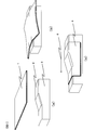
- FIG. 1 shows a hot-forming shaping process in which a prepreg laminate 1 is pressed against a top surface 2 of a mold and is bent along a side surface 3 to form a substantially shaped preform 4.
- the conceptual diagram of is shown.
- the upper surface 2 may be the lower surface, and in the shaping step, a base material may be disposed below the lower surface and bent to the side surface.
- the mold may include other surfaces as long as it includes an upper surface and side surfaces.
- the substantially mold-shaped preform is a prepreg laminate in which the prepreg laminate is formed into a shape including an upper surface or a lower surface and a side surface by bending, and may be in contact with the mold before being removed from the mold. There may be a part floating from the mold. If there is a part that is floating from the mold before it is removed from the mold, the roughly shaped preform means that 80% or more of the mold side surface of the prepreg laminate is at a distance from the mold surface. The state which exists in 3 times or less of the average thickness of.
- the mold used for the shaping process is not particularly limited as long as it has an upper surface and side surfaces. That is, the mold for pressing the prepreg laminate may have irregularities on the upper surface as shown in FIG. 1 and irregularities on the side surfaces as shown in FIG. Both the upper surface and the side surface may be uneven, and the mold longitudinal direction 5 may be a curve.
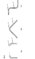
- the cut surface including the preform curved surface portion is, for example, a C type as shown in FIG. 3 (a), an L type as shown in FIG. 3 (b), or a Z type as shown in FIG. 3 (c). You may shape using the type
- the upper surface may be one surface and the side surface may be the other surface, the upper surface may be a ridge line where two surfaces intersect, and the two surfaces may be side surfaces. Also good. It includes a surface different from the upper surface and the side surface as in the Z shape of FIG. 3 (c), and it does not have side surfaces on both sides of the upper surface as in the C type and L type. A side surface may exist only on one side.
- the heated prepreg laminate is subjected to bending shaping along the side surface to obtain a substantially shaped preform.
- a chamber having a heat source or in the vicinity of the heater there is a difference in circumference between the inner periphery and the outer periphery, so it is necessary to perform in-plane deformation in accordance with the unevenness of the mold while sliding between the prepreg layers.
- a unidirectional prepreg that does not have a cut does not deform in the orientation direction of the reinforcing fiber (hereinafter sometimes referred to simply as the fiber direction).
- the embedded prepreg is capable of in-plane deformation while extending in the fiber direction, shape followability is improved as compared with the unidirectional prepreg. Therefore, by using a prepreg group including a cut prepreg as the prepreg laminate, stretching in the fiber direction is allowed, and the shape followability to the uneven shape during bending is improved.
- the prepreg group constituting the prepreg laminate is not particularly limited as long as it includes the cut prepreg. Of the prepreg groups constituting the prepreg laminate, all of the prepreg groups may be cut prepregs. A cut may be inserted only in a prepreg that needs to be stretched.
- the bending forming may be performed by pressing the mold against the mold by performing vacuum suction in the sealed space, or by using a presser for pressing the prepreg laminate to the mold. Alternatively, it may be shaped manually.
- a preform different from the mold used in the shaping process is used to suppress defects such as resin chipping on the fiber-reinforced plastic surface and improve the appearance quality. It is preferable to arrange and solidify. Further, even when out-of-plane deformation is included in the substantially shaped preform, the out-of-plane deformation is absorbed into the surface at the time of solidification, and a fiber-reinforced plastic without out-of-plane deformation can be obtained.
- the mold used for the solidification step may be a shape that assumes the outer peripheral shape of the preform, or may be a shape that is modified in consideration of the thermal shrinkage and flow of the resin.
- mold used for preform is also contained.
- the solidification method when the resin is a thermosetting resin, it is preferable to use an autoclave in order to suppress defects such as voids, but it is also possible to solidify while controlling the heating temperature using vacuum pressure. Good.
- the cuts are preferably distributed with high density and uniformity. That is, when a prepreg in which a plurality of cuts for dividing reinforcing fibers are inserted into at least a part of the region is used as a cut prepreg, 10 diameters arbitrarily selected from the cut region of the cut prepreg When the number of cuts included in a 10 mm circular small region is a population, it is preferable that the average value of the population is 10 or more and the variation coefficient is within 20% (hereinafter, the average of the population). A state where the value is 10 or more is expressed as high density, and a state where the coefficient of variation is within 20% is expressed as homogeneous).
- each cutting can be made small, and so on. Accordingly, the opening of each notch is minimized when the notch prepreg is stretched, the mechanical properties of the fiber reinforced plastic when solidified are not deteriorated, and the surface quality is improved. Further, the distribution of the cuts uniformly distributes the effect of suppressing the local stretch bias of the cut prepreg and improving the mechanical characteristics and the surface quality.
- the length of the reinforcing fiber divided by the cutting is preferably 10 mm or more from the viewpoint of mechanical properties.
- the length of the reinforcing fiber divided by the cutting is more preferably 15 mm or more, and further preferably 20 mm or more.
- the length of the reinforcing fibers can be made into a long cut prepreg of 15 mm or more, while maintaining the followability of the three-dimensional shape and good surface quality, one by one
- a synergistic effect can be expected, that is, a decrease in mechanical properties due to a small depth of cut and an improvement in mechanical properties due to a long reinforcing fiber.
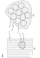
- FIG. 4A shows a conceptual diagram of a cut prepreg 6 including a cut area 8 in which a plurality of cuts 7 are inserted into the prepreg
- FIG. 4B shows a diameter of 10 mm in the cut area 8.
- 10 shows a state where ten circular small regions 9 are extracted. It is preferable to extract the small area densely from the cut area so that the small areas do not overlap. However, when the cut area is not large enough to extract all 10 small areas without overlapping. Alternatively, extraction may be performed so that the small regions overlap each other. However, in order to measure the average value and the coefficient of variation of the above-mentioned population more accurately, a small region should not be set beyond the boundary of the cut region.
- the boundary of the incision area is a line segment group that connects the line segments that connect the end portions of the cut so that all the incisions are included, and the total of the lengths of the line segment groups is minimized.
- notch S2 As a notch pattern, it is preferable that not only Ws is simply reduced, but also the notch S2 closest to any adjacent notch S1 as shown in FIG. 5 (a) does not divide the same reinforcing fiber. Reinforcing fibers that are separated by the notches that are in closest contact with each other become relatively short reinforcing fibers, and this is a factor that degrades the mechanical properties of the fiber-reinforced plastic. Further, when there is a reinforced fiber that is not divided by either the cut S1 or the cut S2 between the cut S1 and the closest cut S2, the cut S1 is obtained when the fiber reinforced plastic is used. And the cut S2 becomes difficult to be connected due to damage, and the mechanical characteristics are improved.
- the reinforcing fiber between the notch S1 and the notch S2 may be divided by the notch closest to the notch S1 and the notch S2, or the reinforcing fiber between the notch S1 and the notch S2 , It does not have to be divided by cutting.
- the width 10 of the band portion sandwiched between the closest cuts is preferably not less than 0.5 times the projected length Ws obtained by projecting the cuts on the plane perpendicular to the reinforcing fibers in the direction perpendicular to the reinforcing fibers. Preferably it is 1 time or more of Ws.
- the distance between the cuts becomes close, and when the closest cuts divide the same reinforcing fiber, very short reinforcing fibers are mixed. Therefore, by providing an interval so that the closest cuts do not divide the same reinforcing fiber, even if it is a high-density cutting pattern, mixing of short reinforcing fibers is suppressed and stable. Mechanical properties can be expressed.
- the cutting is substantially the same length Y (hereinafter, Y is also referred to as the cutting length), and the distance between the closest cuttings is more than 0.5 times Y. Also long cutting prepreg.
- substantially the same length means that all the cut lengths are within ⁇ 5% of the average value of all cut lengths (the same applies hereinafter).
- the cut may be linear or curved, and in any case, the line segment connecting the ends of the cut is the cut length Y.
- the distance between the closest cuts means the shortest distance between the closest cuts.
- the distance between the closest cuts is close, when the fiber reinforced plastic is damaged, damage becomes easy to connect the cuts, so the distance between the closest cuts is 0 of the cut length Y. It is preferably larger than 5 times.
- the distance between the closest cuts is more preferably 0.8 times Y or more, and still more preferably 1.2 times or more Y.
- there is no particular upper limit on the distance between the closest cuts but when giving a high-density cut to the prepreg, the distance between the closest cuts should be 10 times the cut length Y or more. It's not easy.
- the three-dimensional shape followability is improved, and the improvement of mechanical properties can be expected due to the small depth of each cut, but compared to the case where the distance between the cuts is close
- the mechanical properties are further improved when the notches are separated from each other. Therefore, when the cuts are inserted densely, the cut pattern in which the distances between the cuts are separated, that is, the distance between the closest cuts is made larger than 0.5 times the cut length Y. This is particularly important for improving mechanical properties.
- the distance 11 between the closest cuts is set to the cut length Y.
- a more preferable cutting pattern includes a cutting prepreg in which the cutting is inserted obliquely with respect to the orientation direction of the reinforcing fibers.
- the cut is curved, it means that the line segment connecting the ends of the cut is oblique with respect to the orientation direction of the reinforcing fibers.
- the absolute value of ⁇ is 25 ° or less, the mechanical properties, particularly the tensile strength, are remarkably improved. From this viewpoint, the absolute value of ⁇ is more preferably 25 ° or less.
- ⁇ may become smaller as the cut prepreg extends. The smaller ⁇ is, the smaller the cut opening when the cut prepreg is extended, the better the surface quality, and the higher the mechanical properties of the fiber reinforced plastic solidified preform. More preferably, the absolute value of ⁇ is 2 ° or more.
- the cut may be linear or curved. In the case of a curved line, the angle formed by the line segment connecting the ends of the cut and the orientation direction of the reinforcing fibers is ⁇ .
- the absolute value of the angle ⁇ formed by the cutting and the orientation direction of the reinforcing fiber is substantially the same, and further, a positive cutting in which ⁇ is positive and ⁇ is negative.
- An incision prepreg including approximately the same number of negative incisions can be mentioned. That the absolute value of ⁇ is substantially the same means that the angle ⁇ is a deviation within an average value ⁇ 1 ° of the angle ⁇ in all the cuts.
- the inclusion of substantially the same number of positive cuts and negative cuts means that the number of cuts for which ⁇ is positive and the number of cuts for which ⁇ is negative are substantially the same.
- the number of incisions for which ⁇ is positive and the number of incisions for which ⁇ is negative are substantially the same as the percentage based on the number, and the number of ⁇ that is a positive angle and a negative number That is, the number of ⁇ s is 45% or more and 55% or less (the same applies hereinafter).
- it includes substantially the same number of positive incisions and negative incisions, and the interval between any incision and another closest incision existing on the extension line of the incision and the incision between the positive incisions and the negative incisions.
- It is a cut prepreg whose length differs depending on the distance between them.
- the positive cut 12 is arranged on the straight line 14
- the negative cut 13 is arranged on the straight line 15
- the positive cut interval on the straight line 14 is smaller than the negative cut interval on the straight line 15. Is also getting smaller.
- the distance between the positive cuts and the gap between the negative cuts is the same as the length.
- the length of the reinforcing fiber can be increased, and the mechanical properties can be maintained even when the cuts are distributed at a high density.
- the presence of a cut on the extension line of the cut means that the angle between the straight line extending the cut and the straight line connecting the closest points of the target cuts is within 1 °. .
- the interval between any notch and another closest notch that exists on the extension line of the notch it should be a notch pattern with different lengths between the positive notches and the negative notches.
- the length of the reinforcing fiber can be made longer, and even when all the reinforcing fibers are divided in the cutting area, any cutting and the closest to the cutting With another cut, the same reinforcing fiber is not divided, and a cut pattern in which the distance between the closest cuts is longer than 0.5 times the cut length Y is easily obtained. Thereby, the mechanical characteristics can be improved more effectively without impairing the surface quality and the three-dimensional shape followability.
- the incision pattern which is longer than 0.5 times the indentation length Y and substantially all the reinforcing fibers are divided into fiber lengths of 15 mm or more in the incision region, has a three-dimensional shape followability, surface quality, Particularly preferred from the viewpoint of mechanical properties.
- the resin contained in the prepreg and the cut prepreg may be a thermoplastic resin or a thermosetting resin.
- the thermoplastic resin include polyamide (PA), polyacetal, polyacrylate, polysulfone, ABS, and polyester. , Acrylic, polybutylene terephthalate (PBT), polycarbonate (PC), polyethylene terephthalate (PET), polyethylene, polypropylene, polyphenylene sulfide (PPS), polyetheretherketone (PEEK), polyetherimide (PEI), polyetherketone Examples include ketones (PEKK), liquid crystal polymers, vinyl chloride, fluorine resins such as polytetrafluoroethylene, and silicone.
- thermosetting resin Any thermosetting resin may be used as long as the resin undergoes a crosslinking reaction by heat to form at least a partial three-dimensional crosslinked structure.
- thermosetting resins include unsaturated polyester resins, vinyl ester resins, epoxy resins, benzoxazine resins, phenol resins, urea resins, melamine resins, and polyimide resins. Deformation of these resins and resins of two or more blends can also be used. Further, these thermosetting resins may be resins that are self-cured by heat, or may include a curing agent, a curing accelerator, and the like.
- the reinforcing fiber contained in the prepreg and the cut prepreg may be glass fiber, Kevlar fiber, carbon fiber, graphite fiber, boron fiber, or the like.
- carbon fiber is preferable from the viewpoint of specific strength and specific modulus.
- Vf volume content of the reinforcing fiber in the prepreg laminate
- Vf is more preferably 70% or less.
- bridging can be suppressed as Vf is lower.
- Vf is 40% or more.
- a more preferable range of Vf is 45 to 65%, still more preferably 50 to 60%.
- the prepreg and the cut prepreg may be manufactured using a prepreg in which a reinforcing fiber is partially impregnated with a resin (that is, a part is not impregnated).
- a cut prepreg in which the reinforcing fiber is partially impregnated with resin the unimpregnated portion of the reinforcing fiber inside the prepreg becomes an in-plane flow path, and the air trapped between the layers of the cut prepreg during lamination Gases such as volatile components from the cut prepreg are easily discharged out of the cut prepreg (such a gas flow path is referred to as a degassing path).
- the impregnation rate is preferably 10 to 90%.
- the more preferable upper limit of the impregnation rate range is 70%, the more preferable upper limit is 50%, and the more preferable lower limit of the impregnation rate range is 20%.
- the prepreg and the cut prepreg may have a resin layer on the surface thereof. Since the resin layer exists on the surface of the cut prepreg, an interlayer resin layer is formed between the cut prepregs when the cut prepreg is laminated. As a result, when an out-of-plane impact load is applied, cracks are induced in the flexible interlayer resin layer, and due to the high toughness due to the presence of the thermoplastic resin, peeling is suppressed, so that the residual compressive strength after the out-of-plane impact is reduced. It is suitable as a main structural material that requires high safety such as aircraft.
- At least one out-of-plane deformation is included in the preform, and the height of the out-of-plane deformation is 0.5 to 3 times the average thickness of the prepreg laminate.
- the average thickness of the prepreg laminate is a thickness obtained by measuring a flat prepreg laminate before shaping at a measurement pressure of 5 N using a ratchet micrometer with a flat tip, and the end of the prepreg laminate is 3 It is set as the average value of the thickness which measured the part.
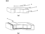
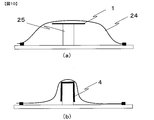
- the out-of-plane deformation of the preform refers to a difference in height between portions having a height difference such as a convex portion and a flat portion of the end surface when the end surface 16 of the preform after bending is shaped as shown in FIG. It means a maximum value of 17.
- the difference in height between the concave portion and the flat portion, or between the concave portion and the convex portion means the maximum height difference at the end of the prepreg laminate being shaped.
- this is an effective method for a place where a high pressure is applied during solidification, such as the flange 26 shown in FIG.
- the out-of-plane deformation is too large, it cannot be absorbed in the plane, and the height of the out-of-plane deformation is preferably 3 times or less the average thickness of the prepreg.
- the shaping step it is preferable to bend and shape so that the out-of-plane deformation of the prepreg laminate is always 3 times or less of the average thickness of the prepreg laminate. More preferably, it is 1 time or less.
- a specific method for controlling the out-of-plane deformation of the prepreg laminate use a device that has multiple pressers in the mold that compress the prepreg laminate in the out-of-plane direction, and detect the out-of-plane deformation while detecting it with a sensor. May be formed, and bending shape may be formed while pressing a portion having large out-of-plane deformation by hand while visually confirming a change in thickness.
- a preliminary bending shaping test or simulation may be performed to determine the location and timing of pressing the prepreg laminate so that the out-of-plane deformation is maintained at 3 times or less the average thickness of the prepreg laminate during the shaping process.
- the shaping step at least a part of the substantially shaped preform is pressed against the mold while applying a shearing force to be flattened.
- a fiber-reinforced plastic having a good appearance quality even when there is out-of-plane deformation in the preform as described above, but when setting the preform on the female mold in the solidification process, When out-of-plane deformation exists on the side surface that is difficult to impart, the out-of-plane deformation of the preform may be flattened in advance.
- FIG. 6 shows a conceptual diagram in which the preform 4 including out-of-plane deformation is pressed against the mold while applying a shearing force 18.
- the shear deformation is preferably in the direction of extending the out-of-plane deformation.
- the mold may be pushed with a roller or the like, or the out-of-plane deformation may be flattened while rubbing manually.
- it is preferable to perform in the temperature region where the prepreg laminate is softened because the in-plane of the prepreg laminate is easily deformed.
- the out-of-plane deformation of the prepreg laminate in the shaping step 3 can be easily flattened by a shearing force, which is preferable.
- the preform when pressing and flattening a preform having a substantially mold shape against a mold while applying a shearing force, the preform may be flattened by pressing against the mold while applying a shearing force to the entire preform. Although it is possible, it is sufficient to flatten by pressing against a mold while applying a shearing force only to a specific portion having large irregularities.
- the preform is solidified by allowing out-of-plane deformation and a case where the preform is solidified after being flattened.
- the pressure applied to the place where the deformation has occurred is large, for example, when a pressure of 3 MPa or more can be applied, the out-of-plane deformation may be allowed, but when the large pressure cannot be applied, the out-of-plane deformation is flattened in advance. It is preferable to keep.
- the present invention is preferably applicable to aircraft girders and the like, and also provides a fiber-reinforced plastic having excellent mechanical properties and including a curved surface. That is, a fiber reinforced plastic including a resin and a reinforced fiber, and having a flat surface portion and a curved surface portion.
- the fiber reinforced plastic has a reinforced fiber oriented in one direction at least partially divided, and The resin part P exists between the fiber bundles adjacent to each other in the orientation direction, and the layer having the resin part P in which the line segment connecting the end parts of the resin part P is arranged obliquely with respect to the orientation direction of the reinforcing fibers.
- the fiber reinforced plastic is a fiber reinforced plastic including the layer A on the side closer to the outer periphery than to the inner periphery of the curved surface portion.
- the manufacturing method of such a fiber reinforced plastic of this invention is not specifically limited, For example, it can obtain by the manufacturing method of this invention including the above-mentioned lamination process, a shaping process, and a solidification process.
- the curved surface portion refers to a portion where the radius of curvature of the outer diameter of the fiber reinforced plastic is 1 to 100 mm.
- a plurality of layers A may be present, and when a plurality of layers A are present, the orientation directions of the reinforcing fibers in each layer A may be the same or different.
- the orientation state of the reinforcing fibers in the portion excluding the layer A is not particularly limited, but the orientation in one direction can increase the volume content of the reinforcing fibers, and the mechanical properties in the orientation direction of the reinforcing fibers are remarkably high. Therefore, it is preferable.
- the cross section of the reinforcing fibers can take various forms from linear to circular.
- the cross-sections of the reinforcing fibers are the same.
- a cross section perpendicular to the fiber direction is a circle
- a cross section oblique to the fiber direction is an ellipse.
- the coefficient of variation in the major axis of the cross section of 100 randomly selected reinforcing fibers is present.
- the layer A has a resin portion P between fiber bundles adjacent to the orientation direction of the reinforcing fiber (hereinafter referred to as fiber direction).
- fiber direction the resin portion P between fiber bundles adjacent to each other in the fiber direction in the fiber reinforced plastic made of short fibers.
- the resin part has a low load and is likely to be a starting point of damage. Therefore, in order for the resin part to transmit the load between the adjacent fiber bundles by shear stress, the line segment connecting the ends of the resin part P should be arranged obliquely with respect to the orientation direction of the reinforcing fibers. Is preferred.
- the length of all the reinforcing fibers is in the range of 10 mm to 50 mm.
- the fiber reinforced plastic of the present invention includes the layer A including the resin portion P in a portion closer to the outer peripheral side than the inner peripheral side of the curved surface portion.
- the reinforcing fiber is filled in every corner of the curved surface.
- the thickness of the layer A in the curved surface portion is made thinner than the thickness of the layer A in the flat surface portion.
- the resin portion P is also thinned, and damage can be suppressed, which is preferable.
- the fiber-reinforced plastic of the present invention may be formed from a prepreg laminate including a cut prepreg obtained by inserting a cut into a prepreg in which reinforcing fibers are aligned in one direction, and short fibers are aligned in one direction.
- a prepreg impregnated with a resin may be used.
- the fiber reinforced plastic of the present invention when any two resin lines P in the plane of the layer A are in contact with the contour of the resin part P, and two parallel lines are drawn with the shortest distance, It is a fiber reinforced plastic having an average parallel line distance of 0.2 mm or less.
- the width of the resin part P When the distance between two parallel lines that are in contact with the contour of the resin part P and the distance is the shortest is the width of the resin part P, the smaller the width of the resin part P, the more the reinforcing fibers adjacent to each other across the resin part P. It is preferable that load transmission is performed efficiently.
- the average value of the width of the resin part P is more preferably 0.15 mm or less.
- the average value of the width of the resin portion P means that the surface of the layer A is shaved with a polishing machine or the like as shown in FIG. 7, and the surface of the resin portion P is taken from an image obtained by using a photographing device such as a digital microscope. It is obtained by extracting 10 P and calculating the average value of the width of the resin part P.
- the width of the resin part P is a distance 27 between two parallel lines in contact with the contour of the resin part P as shown in FIG. 8, but the means for drawing the two parallel lines is drawn by hand after printing the image. Alternatively, a measuring means provided in the digital microscope may be used.
- a fiber reinforced plastic in which the total volume of the resin parts P in the layer A is 5% or less of the volume of the layer A is used.
- the resin part P is preferably 5% or less, more preferably 3% or less of the total volume of the fiber reinforced plastic.
- the surface quality of the fiber reinforced plastic is not deteriorated, and defects in the structure are not caused.
- the volume ratio of the resin part P in a curved surface part is 0.1% or more of the volume of the layer A in a curved surface part.
- the volume of the resin part P in the layer A is calculated using the area of the resin part P measured from the surface of the layer A assuming that the resin part P has the same shape in the thickness direction.
- the area of one resin part P is defined as 1/2 of the product of the width of the resin part P and the length of the resin part P.
- the length of the resin portion P is a distance 28 between two parallel lines that are in contact with the contour of the resin portion P and have the longest distance.
- An area of the surface A of the layer A having a size of 10 mm ⁇ 10 mm is observed, and the total area (mm 2 ) of all the resin parts P existing in the area is the volume ratio (%) of the resin part P in the layer A.
- All the prepreg groups constituting the prepreg laminate were cut prepregs.
- the orientation direction of the reinforcing fiber of the cut prepreg is [+ 45 ° / 0 ° / ⁇ 45 °. / 90 °] was laminated so as to be 2 s, and was adhered by vacuum drawing for 30 minutes after lamination to obtain a prepreg laminated body of 150 mm ⁇ 150 mm.
- ⁇ Incision distribution evaluation> Take multiple images of the surface of the cut prepreg with a digital microscope with a magnification of 10x, connect the images on the screen, display the surface of the cut prepreg 50mm x 50mm on the screen, and use the measurement software to make a 10mm line
- Ten circles were drawn so that the centers of three adjacent circles form an equilateral triangle, as in the case of the arrangement of pins for boring.
- the distance between the centers of adjacent circles was 12 mm.
- the number of cuts included in or touching each circle was counted as a population, and the average value and coefficient of variation of the population were calculated.
- the prepreg laminate is arranged on the upper surface of the mold including the upper surface and the side surface in FIG. 9 and the C-shaped cross section continues in the longitudinal direction so that 0 ° of the prepreg laminate is in the longitudinal direction, and bent along the side surface. It was shaped to obtain a substantially shaped preform.
- the forming method is as follows: a mold is placed on a plate, a prepreg laminate is placed thereon, and after sealing with a bag film, vacuuming is performed and the bag film is sucked into the mold, and at the same time, the prepreg laminate is bent. The method was shaped.
- the preform was removed from the mold, set in a female mold different from the mold used for bending, and cured with an autoclave at 130 ° C. for 1.5 hours while being covered with a bag film and evacuated.
- the surface of the manufactured fiber reinforced plastic was visually confirmed and divided into the following three stages.
- the waviness of the reinforcing fiber refers to a fiber reinforced plastic whose surface is disturbed to deteriorate the surface quality on the surface of the fiber reinforced plastic.
- A The opening of the notch is hardly recognized and the swell of the reinforcing fiber is not generated.
- B The opening of the notch is recognized but the swell of the reinforcing fiber is not generated.
- C The swell of the reinforcing fiber is generated. is doing.
- the width of the resin part P in the fiber reinforced plastic was 0.24 mm, and the volume of the resin part P was 5.7%.
- the tensile strength was 490 MPa.
- the cutting pattern is the pattern shown in FIG. 5A.
- the length of the cut reinforcing fibers is 20 mm
- the projected length Ws is 0.2 mm
- the cutting is projected onto a plane perpendicular to the orientation direction of the reinforcing fibers.
- a prepreg laminate was formed of a cut prepreg having an angle ⁇ of 14 ° between the orientation of the reinforced fibers and the reinforcing fiber. In the incision distribution evaluation, the average value of the population was 17.5, and the coefficient of variation was 8%.
- Example 3 A prepreg laminate was formed with the prepreg having the cutting pattern shown in FIG.
- the angle ⁇ formed with the orientation direction is 20 °.
- it includes substantially the same number of positive cuts where ⁇ is positive and negative cuts where ⁇ is negative, and the interval between the cuts on the extended line of the cut is a positive cut (2.8 mm) and a negative cut ( 17mm).
- the average value of the population was 15.1 and the coefficient of variation was 6%.
- the cuts were distributed with high density and uniformity.
- the width and volume of the resin part P in the fiber reinforced plastic were both smaller than in Example 2.
- the tensile strength was further improved as compared with Example 2.
- Example 4 Using the same cut prepreg laminate as in Example 3, not only bending shaping but also the flange portion was shaped in the shaping step, and a preform having a flange as shown in FIG. 6B was produced. Out-of-plane deformation remained at the end of the preform, and its height was 1.8 times the thickness of the prepreg laminate. Although it seemed possible to reduce the out-of-plane deformation by applying a shearing force from the out-of-plane, it requires labor, so it is set in a female mold that can apply pressure to the flange while there is an out-of-plane deformation. In the same manner as in Examples 1 to 3, fiber-reinforced plastics were produced. As a result, the out-of-plane deformation existing in the flange disappeared, and a fiber-reinforced plastic having a flat flange could be manufactured.
- the present invention can provide a method for producing a fiber reinforced plastic that can be formed into a wrinkle-free preform by hot forming, exhibits high mechanical properties when used as a fiber reinforced plastic, and has a complicated shape.
- a fiber reinforced plastic having high mechanical properties can be provided, it can be developed for structural uses such as aircraft, spacecraft, automobiles, railways, ships, electrical appliances, and sports.
- Prepreg laminate 2 Mold upper surface 3: Mold side surface 4: Preform 5: Mold longitudinal direction 6: Cut prepreg 7: Cut 8: Cut region 9: Small region 10: Between the closest cuts Width of band portion present in 11: Distance between closest cuts 12: Positive cut 13: Negative cut 14: Straight line including positive cut 15: Straight line including negative cut 16: End face of prepreg laminate during shaping 17: Out-of-plane deformation 18: Shear force 24: Bag film 25: Mold shown in FIG. 26: Flange portion 27: Width of resin portion P 28: Length of resin portion P
Abstract
Description
一方向に配向した強化繊維と樹脂とを含むプリプレグの、少なくとも一部の領域に強化繊維を分断する複数の切込が挿入されたプリプレグを切込プリプレグとすると、切込プリプレグを含むプリプレグ群を、複数枚積層してプリプレグ積層体を得る積層工程と、
プリプレグ積層体を、上面と側面を含む型の上面に配置又は下面と側面を含む型の下面に配置し、側面に沿って曲げ賦形し、略型形状としたプリフォームを得る賦形工程と、
賦形工程で用いた型とは異なる型にプリフォームを配置し、固化する、固化工程を含む、繊維強化プラスチックの製造方法、である。 The manufacturing method of the fiber reinforced plastic of this invention has the following structure in order to solve this subject. That is,
When a prepreg having a plurality of cuts for dividing the reinforcing fiber in at least a part of the prepreg including reinforced fibers and resin oriented in one direction is a cut prepreg, the prepreg group including the cut prepreg A laminating step of obtaining a prepreg laminate by laminating a plurality of sheets,
A shaping step of obtaining a preform having a prepreg laminate, which is disposed on an upper surface of a mold including an upper surface and a side surface, or disposed on a lower surface of a mold including a lower surface and a side surface, and is bent and shaped along the side surface; ,
A method for producing a fiber reinforced plastic, including a solidification step, in which a preform is placed in a different mold from the mold used in the shaping step and solidified.
樹脂と強化繊維とを含み、平面部と曲面部とを有する繊維強化プラスチックであって、
繊維強化プラスチックは、少なくとも一部が分断された強化繊維が一方向に配向し、かつ強化繊維の配向方向に隣接する繊維束間に樹脂部Pが存在し、
樹脂部Pの端部同士を結んだ線分が、強化繊維の配向方向に対して斜めに配置された樹脂部Pを有する層を層Aとするとき、繊維強化プラスチックは曲面部の内周よりも外周に近い側に層Aを含む繊維強化プラスチック、である。 The fiber-reinforced plastic of the present invention has the following configuration. That is,
A fiber reinforced plastic including a resin and a reinforced fiber, and having a flat surface portion and a curved surface portion,
In the fiber reinforced plastic, at least a part of the reinforced fiber is oriented in one direction, and the resin portion P exists between the fiber bundles adjacent to the orientation direction of the reinforced fiber,
When the line segment connecting the ends of the resin part P is a layer A having the resin part P arranged obliquely with respect to the orientation direction of the reinforcing fiber, the fiber reinforced plastic is from the inner periphery of the curved part. Is also a fiber reinforced plastic including the layer A on the side close to the outer periphery.


“トレカ”(商標登録)プリプレグシートP3052S-15(強化繊維:T700S、樹脂:2500、強化繊維の体積含有率:56%、片面離型紙を積層)に、所定の位置に刃を配置した回転刃ローラーに押し当てて、プリプレグを貫通する切込を挿入した。切込領域はプリプレグ全域とし、全ての強化繊維を切込によって切断した。いずれの実施例においても、200mm×200mmの切込プリプレグの樹脂を400℃にて焼き飛ばした際、200mmの強化繊維が残っておらず、全ての強化繊維が分断されていることを確認した。 <Preparation of prepreg laminate>
Rotating blade with blades placed in a predetermined position on “Torayca” (registered trademark) prepreg sheet P3052S-15 (reinforced fiber: T700S, resin: 2500, volume content of reinforcing fiber: 56%, single-sided release paper laminated) A notch penetrating the prepreg was inserted by pressing against the roller. The cutting area was the entire prepreg, and all the reinforcing fibers were cut by cutting. In any of the examples, when 200 mm × 200 mm cut prepreg resin was burned off at 400 ° C., it was confirmed that 200 mm reinforcing fibers did not remain and all the reinforcing fibers were divided.
切込プリプレグの表面を倍率10倍のデジタルマイクロスコープで複数枚撮影し、画面上で画像を連結し、切込プリプレグの表面50mm×50mmを画面上に表示させ、計測ソフトウェアを用いて直系10mmの円を、ボーリングのピンの配置のように、隣接する3つ円の中心が正三角形を描くように10個描いた。隣接する円の中心間距離は12mmとした。各円に含まれる、もしくは接する切込の数をカウントして母集団とし、母集団の平均値と変動係数を算出した。 <Incision distribution evaluation>
Take multiple images of the surface of the cut prepreg with a digital microscope with a magnification of 10x, connect the images on the screen, display the surface of the cut prepreg 50mm x 50mm on the screen, and use the measurement software to make a 10mm line Ten circles were drawn so that the centers of three adjacent circles form an equilateral triangle, as in the case of the arrangement of pins for boring. The distance between the centers of adjacent circles was 12 mm. The number of cuts included in or touching each circle was counted as a population, and the average value and coefficient of variation of the population were calculated.
図9の上面と側面を含み、C型の断面が長手方向に続く形状の型の上面に、プリプレグ積層体の0°が長手方向となるようにプリプレグ積層体を配置し、側面に沿って曲げ賦形し、略型形状のプリフォームを得た。賦形方法は図10のように、板の上に型を置き、その上にプリプレグ積層体を置き、バグフィルムで密封後に真空引きを行いバグフィルムが型に吸い寄せられると同時にプリプレグ積層体が曲げ賦形される方法とした。面外変形が生じた場合は手作業でせん断力を加えながら型に押し付けて、平坦化した。この賦形工程は、60℃に温調されたオーブンの中で行った。型は、図9中のhが2mmの型と6mmの型を準備した。完成したプリフォームの三次元形状追従性について、以下の3段階で評価した。
A:一度目の曲げ賦形で形状に追従することができた。
B:一度目の曲げ賦形後は面外変形が生じたが、せん断力を与えながら型に押し付けることで面外変形を平坦化することができた。
C:一度目の曲げ賦形後は面外変形が生じたので、せん断力を加えながら型に押し付けたが、面外変形を平坦化することができず、面外変形が残った。 <Evaluation of formability>
The prepreg laminate is arranged on the upper surface of the mold including the upper surface and the side surface in FIG. 9 and the C-shaped cross section continues in the longitudinal direction so that 0 ° of the prepreg laminate is in the longitudinal direction, and bent along the side surface. It was shaped to obtain a substantially shaped preform. As shown in FIG. 10, the forming method is as follows: a mold is placed on a plate, a prepreg laminate is placed thereon, and after sealing with a bag film, vacuuming is performed and the bag film is sucked into the mold, and at the same time, the prepreg laminate is bent. The method was shaped. When out-of-plane deformation occurred, it was flattened by pressing it against the mold while manually applying a shearing force. This shaping process was performed in an oven controlled at 60 ° C. As the mold, a mold having h of 2 mm and a mold of 6 mm in FIG. 9 was prepared. The three-dimensional shape followability of the completed preform was evaluated in the following three stages.
A: The shape could be followed by the first bending.
B: Although the out-of-plane deformation occurred after the first bending shaping, the out-of-plane deformation could be flattened by pressing it against the mold while applying a shearing force.
C: Since the out-of-plane deformation occurred after the first bending, the sheet was pressed against the mold while applying a shearing force. However, the out-of-plane deformation could not be flattened, and the out-of-plane deformation remained.
上記プリフォームを型から取り外し、曲げ賦形に用いた型とは別の雌型にセットし、型ごとバグフィルムで被って真空引きを行いながらオートクレーブで130℃、1.5時間で硬化した。製造された繊維強化プラスチックの表面を目視で確認し、以下の3段階に分けた。強化繊維のうねりとは、繊維強化プラスチックの表面において、強化繊維の配向に乱れが生じ、表面品位を悪化させているものを指す。
A:切込の開口がほとんど認識できず、強化繊維のうねりも発生していない
B:切込の開口が認識されるが、強化繊維のうねりが発生していない
C:強化繊維のうねりが発生している。 <Surface quality of fiber reinforced plastic>
The preform was removed from the mold, set in a female mold different from the mold used for bending, and cured with an autoclave at 130 ° C. for 1.5 hours while being covered with a bag film and evacuated. The surface of the manufactured fiber reinforced plastic was visually confirmed and divided into the following three stages. The waviness of the reinforcing fiber refers to a fiber reinforced plastic whose surface is disturbed to deteriorate the surface quality on the surface of the fiber reinforced plastic.
A: The opening of the notch is hardly recognized and the swell of the reinforcing fiber is not generated. B: The opening of the notch is recognized but the swell of the reinforcing fiber is not generated. C: The swell of the reinforcing fiber is generated. is doing.
得られた繊維強化プラスチックにおいて、図9における型の上面の傾斜のある箇所の中央部を長手方向に垂直な平面で切断し、矩形の断面を得た。さらに、上面に相当する箇所を10mm×10mmで切り出し、曲面部において外周に近い側となっている8層について、強化繊維の断面形状を観察した。各層において、無作為に選んだ100個の強化繊維の断面の長径を計測し、長径の変動係数が20%以下の場合に、該層は強化繊維が一方向であるとみなした。 <Evaluation of orientation of reinforcing fibers>
In the obtained fiber reinforced plastic, the central portion of the inclined portion of the upper surface of the mold in FIG. 9 was cut along a plane perpendicular to the longitudinal direction to obtain a rectangular cross section. Furthermore, the portion corresponding to the upper surface was cut out at 10 mm × 10 mm, and the cross-sectional shape of the reinforcing fiber was observed for the 8 layers on the curved surface side that was close to the outer periphery. In each layer, the major axis of the cross section of 100 reinforcing fibers selected at random was measured, and when the variation coefficient of the major axis was 20% or less, the layer considered that the reinforcing fiber was unidirectional.
強化繊維の配向状態評価で、強化繊維が一方向であるとみなされた層に対して、表層から順番に研磨機で層の表面を削りだした。樹脂部Pが確認できた層について、10個ずつ樹脂部Pの幅を測定して平均値を算出した。 <Measurement of width of resin part P>
In the evaluation of the orientation state of the reinforcing fibers, the surface of the layer was scraped in order from the surface layer with a polishing machine with respect to the layer in which the reinforcing fibers were considered to be unidirectional. About the layer which the resin part P was able to be confirmed, the width of the resin part P was measured 10 pieces at a time, and the average value was computed.
樹脂部Pの幅の測定と同時に、樹脂部Pの長さの測定を行った。10mm×10mmの正方形の表面の画像内に含まれる全ての樹脂部Pの幅×長さ×1/2の和を計算し、100mm2で割ることで、層Aに含まれる樹脂部Pの体積の割合を計算した。 <Volume ratio measurement of resin part P>
Simultaneously with the measurement of the width of the resin part P, the length of the resin part P was measured. Calculate the sum of the width x length x 1/2 of all the resin parts P included in the image of the 10 mm x 10 mm square surface and divide by 100 mm 2 to obtain the volume of the resin part P contained in the layer A The percentage of was calculated.
曲面部を有する繊維強化プラスチックの強度比較が困難であるため、平板状の試験片を準備し引張試験を行った。350mm×350mmに切り出した切込プリプレグを積層構成が[+45°/0°/-45°/90°]2sとなるように積層し、オートクレーブで130℃、1.5時間で硬化させた。 <Mechanical properties>
Since it was difficult to compare the strength of fiber reinforced plastics having curved surfaces, flat test pieces were prepared and subjected to a tensile test. Cut prepregs cut out to 350 mm × 350 mm were laminated so that the laminated structure was [+ 45 ° / 0 ° / −45 ° / 90 °] 2 s, and cured in an autoclave at 130 ° C. for 1.5 hours.
切込パターンが図5(a)に示すパターンで、分断された強化繊維の長さは20mm、切込を強化繊維の配向方向に直角な平面に投影した投影長さWs=5mm、切込と強化繊維の配向方向とのなす角度θが45°の切込プリプレグでプリプレグ積層体を構成した。 Example 1
The cutting pattern is the pattern shown in FIG. 5 (a), the length of the cut reinforcing fiber is 20 mm, the projected length Ws = 5 mm, which is a projection of the cutting on a plane perpendicular to the orientation direction of the reinforcing fiber, A prepreg laminate was formed of a cut prepreg having an angle θ of 45 ° with the orientation direction of the reinforcing fibers.
切込パターンが図5(a)に示すパターンで、分断された強化繊維の長さは20mm、切込を強化繊維の配向方向に直角な平面に投影した投影長さWs=0.2mm、切込と強化繊維の配向方向とのなす角度θが14°の切込プリプレグでプリプレグ積層体を構成した。切込分布評価では、母集団の平均値は17.5、変動係数は8%であった。 (Example 2)
The cutting pattern is the pattern shown in FIG. 5A. The length of the cut reinforcing fibers is 20 mm, the projected length Ws is 0.2 mm, and the cutting is projected onto a plane perpendicular to the orientation direction of the reinforcing fibers. A prepreg laminate was formed of a cut prepreg having an angle θ of 14 ° between the orientation of the reinforced fibers and the reinforcing fiber. In the incision distribution evaluation, the average value of the population was 17.5, and the coefficient of variation was 8%.
切込パターンが図5(b)に示した切込プリプレグでプリプレグ積層体を構成した。全ての切込の長さは、分断された強化繊維の長さは20mm、切込を強化繊維の配向方向に直角な平面に投影した投影長さWs=0.2mm、切込と強化繊維の配向方向とのなす角度θが20°である。さらに、θが正である正切込とθが負である負切込を略同数含み、切込の延長線上に存在する切込同士の間隔が、正切込(2.8mm)と負切込(17mm)とで異なる。切込分布評価では、母集団の平均値は15.1、変動係数は6%であり、高密度かつ均質に切込が分布していた。 (Example 3)
A prepreg laminate was formed with the prepreg having the cutting pattern shown in FIG. The length of all the cuts is 20 mm for the split reinforcing fiber, the projected length Ws = 0.2 mm projected on the plane perpendicular to the orientation direction of the reinforcing fibers, The angle θ formed with the orientation direction is 20 °. Furthermore, it includes substantially the same number of positive cuts where θ is positive and negative cuts where θ is negative, and the interval between the cuts on the extended line of the cut is a positive cut (2.8 mm) and a negative cut ( 17mm). In the cut distribution evaluation, the average value of the population was 15.1 and the coefficient of variation was 6%. The cuts were distributed with high density and uniformity.
実施例3と同じ切込プリプレグ積層体を用いて、賦形工程で曲げ賦形だけでなく、フランジ部も賦形し、図6(b)のようにフランジのあるプリフォームを作製した。プリフォームの端に面外変形が残っており、その高さはプリプレグ積層体の厚みの1.8倍であった。面外からせん断力を与えることで面外変形を少なくすることも可能であると思えたが、労力を要するため、面外変形が存在したままフランジにも圧力を与えることのできる雌型にセットし、実施例1~3と同じように繊維強化プラスチックを製造した。その結果、フランジに存在していた面外変形は消え、平坦なフランジを有する繊維強化プラスチックを製造することができた。 (Example 4)
Using the same cut prepreg laminate as in Example 3, not only bending shaping but also the flange portion was shaped in the shaping step, and a preform having a flange as shown in FIG. 6B was produced. Out-of-plane deformation remained at the end of the preform, and its height was 1.8 times the thickness of the prepreg laminate. Although it seemed possible to reduce the out-of-plane deformation by applying a shearing force from the out-of-plane, it requires labor, so it is set in a female mold that can apply pressure to the flange while there is an out-of-plane deformation. In the same manner as in Examples 1 to 3, fiber-reinforced plastics were produced. As a result, the out-of-plane deformation existing in the flange disappeared, and a fiber-reinforced plastic having a flat flange could be manufactured.
切込の入っていないプリプレグのみでプリプレグ積層体を構成した。h=2mm、6mmの場合共に、面外変形が生じ、平坦化もできなかった。硬化後の表面品位はh=2mm、6mmの場合共に繊維のうねりが確認できた。 (Comparative Example 1)
A prepreg laminate was composed only of prepregs that were not cut. In both cases of h = 2 mm and 6 mm, out-of-plane deformation occurred and flattening was not possible. When the surface quality after curing was h = 2 mm and 6 mm, the waviness of the fibers could be confirmed.

2:型の上面
3:型の側面
4:プリフォーム
5:型の長手方向
6:切込プリプレグ
7:切込
8:切込領域
9:小領域
10:最近接する切込間に存在する帯部の幅
11:最近接する切込間距離
12:正切込
13:負切込
14:正切込を含む直線
15:負切込を含む直線
16:賦形中のプリプレグ積層体の端面
17:面外変形
18:せん断力
24:バグフィルム
25:図9に示した型
26:フランジ部
27:樹脂部Pの幅
28:樹脂部Pの長さ 1: Prepreg laminate 2: Mold upper surface 3: Mold side surface 4: Preform 5: Mold longitudinal direction 6: Cut prepreg 7: Cut 8: Cut region 9: Small region 10: Between the closest cuts Width of band portion present in 11: Distance between closest cuts 12: Positive cut 13: Negative cut 14: Straight line including positive cut 15: Straight line including negative cut 16: End face of prepreg laminate during shaping 17: Out-of-plane deformation 18: Shear force 24: Bag film 25: Mold shown in FIG.
26: Flange portion 27: Width of resin portion P 28: Length of resin portion P
Claims (8)
- 一方向に配向した強化繊維と樹脂とを含むプリプレグの、少なくとも一部の領域に強化繊維を分断する複数の切込が挿入されたプリプレグを切込プリプレグとすると、切込プリプレグを含むプリプレグ群を、複数枚積層してプリプレグ積層体を得る積層工程と、
プリプレグ積層体を、上面と側面を含む型の上面に配置又は下面と側面を含む型の下面に配置し、側面に沿って曲げ賦形し、略型形状としたプリフォームを得る賦形工程と、
賦形工程で用いた型とは異なる型にプリフォームを配置し、固化する、固化工程を含む、繊維強化プラスチックの製造方法。 When a prepreg having a plurality of cuts for dividing the reinforcing fiber in at least a part of the prepreg including reinforced fibers and resin oriented in one direction is a cut prepreg, the prepreg group including the cut prepreg A laminating step of obtaining a prepreg laminate by laminating a plurality of sheets,
A shaping step of obtaining a preform having a prepreg laminate, which is disposed on an upper surface of a mold including an upper surface and a side surface, or disposed on a lower surface of a mold including a lower surface and a side surface, and is bent and shaped along the side surface; ,
A method for producing a fiber-reinforced plastic, including a solidification step, in which a preform is placed in a different mold from the mold used in the shaping process and solidified. - 前記切込プリプレグは、切込プリプレグの前記領域内から任意に選択される、10個の直径10mmの円形の小領域内に含まれる切込の個数を母集団とした場合に、母集団の平均値が10以上、かつ変動係数が20%以内である、請求項1に記載の繊維強化プラスチックの製造方法。 The incision prepreg is an average of the population when the number of incisions included in 10 small circular regions having a diameter of 10 mm, which is arbitrarily selected from the region of the incision prepreg, is a population. The method for producing a fiber-reinforced plastic according to claim 1, wherein the value is 10 or more and the coefficient of variation is within 20%.
- 切込と強化繊維の配向方向とのなす角度θの絶対値が、実質的に同一であり、θが正である正切込とθが負である負切込を略同数含み、任意の切込と、当該切込の延長線上に存在する最近接する別の切込との間隔について、正切込同士の間隔と負切込同士の間隔とで長さが異なる、請求項2に記載の切込プリプレグ。 The absolute value of the angle θ formed by the incision and the orientation direction of the reinforcing fiber is substantially the same, and includes substantially the same number of positive incisions in which θ is positive and negative incisions in which θ is negative. And the distance between the closest notch existing on the extension line of the notch and the distance between the positive notches and the distance between the negative notches, the notch prepreg according to claim 2, .
- プリフォームに面外変形が少なくとも一つ含まれ、該面外変形の高さがプリプレグ積層体の平均厚みの0.5倍以上3倍以下である請求項1~3のいずれかに記載の繊維強化プラスチックの製造方法。 The fiber according to any one of claims 1 to 3, wherein the preform includes at least one out-of-plane deformation, and the height of the out-of-plane deformation is 0.5 to 3 times the average thickness of the prepreg laminate. A method of manufacturing reinforced plastics.
- 賦形工程において、略型形状としたプリフォームの少なくとも一部に対して、せん断力を加えながら前記型に押し付けて平坦化する、請求項1~4のいずれかに記載の繊維強化プラスチックの製造方法。 The production of a fiber-reinforced plastic according to any one of claims 1 to 4, wherein in the shaping step, at least a part of the preform having a substantially mold shape is pressed against the mold while applying a shearing force to be flattened. Method.
- 樹脂と強化繊維とを含み、平面部と曲面部とを有する繊維強化プラスチックであって、
繊維強化プラスチックは、少なくとも一部が分断された強化繊維が一方向に配向し、かつ強化繊維の配向方向に隣接する繊維束間に樹脂部Pが存在し、
樹脂部Pの端部同士を結んだ線分が、強化繊維の配向方向に対して斜めに配置された樹脂部Pを有する層を層Aとするとき、繊維強化プラスチックは曲面部の内周よりも外周に近い側に層Aを含む繊維強化プラスチック。 A fiber reinforced plastic containing a resin and a reinforced fiber and having a flat surface portion and a curved surface portion,
In the fiber reinforced plastic, at least a part of the reinforced fiber is oriented in one direction, and the resin portion P exists between the fiber bundles adjacent to the orientation direction of the reinforced fiber,
When the line segment connecting the ends of the resin part P is a layer A having the resin part P arranged obliquely with respect to the orientation direction of the reinforcing fiber, the fiber reinforced plastic is from the inner periphery of the curved part. A fiber reinforced plastic containing layer A on the side closer to the outer periphery. - 層Aの面内の任意の樹脂部Pにおいて、該樹脂部Pの輪郭と接し、距離が最短となる2本の平行線を描いたとき、平行線の距離の平均値が0.2mm以下である、請求項6に記載の繊維強化プラスチック。 In an arbitrary resin part P in the plane of the layer A, when drawing two parallel lines in contact with the contour of the resin part P and having the shortest distance, the average value of the parallel line distance is 0.2 mm or less. The fiber-reinforced plastic according to claim 6.
- 層A中の樹脂部Pの体積の合計が、該層Aの体積の5%以下である、請求項6または7に記載の繊維強化プラスチック。 The fiber-reinforced plastic according to claim 6 or 7, wherein the total volume of the resin part P in the layer A is 5% or less of the volume of the layer A.
Priority Applications (7)
| Application Number | Priority Date | Filing Date | Title |
|---|---|---|---|
| ES17766567T ES2866928T3 (en) | 2016-03-16 | 2017-03-10 | Fiber Reinforced Plastic Manufacturing Method |
| US16/085,327 US20190077048A1 (en) | 2016-03-16 | 2017-03-10 | Method of manufacturing fiber-reinforced plastic and fiber-reinforced plastic |
| CN201780008387.7A CN108602284B (en) | 2016-03-16 | 2017-03-10 | Method for producing fiber-reinforced plastic and fiber-reinforced plastic |
| KR1020187017019A KR20180124834A (en) | 2016-03-16 | 2017-03-10 | Method of manufacturing fiber-reinforced plastic |
| JP2017514944A JP6962191B2 (en) | 2016-03-16 | 2017-03-10 | Manufacturing method of fiber reinforced plastic and fiber reinforced plastic |
| CA3016198A CA3016198A1 (en) | 2016-03-16 | 2017-03-10 | Manufacturing method for fiber-reinforced plastic and fiber-reinforced plastic |
| EP17766567.6A EP3431272B1 (en) | 2016-03-16 | 2017-03-10 | Manufacturing method for fiber-reinforced plastic |
Applications Claiming Priority (2)
| Application Number | Priority Date | Filing Date | Title |
|---|---|---|---|
| JP2016051892 | 2016-03-16 | ||
| JP2016-051892 | 2016-03-16 |
Publications (1)
| Publication Number | Publication Date |
|---|---|
| WO2017159567A1 true WO2017159567A1 (en) | 2017-09-21 |
Family
ID=59850372
Family Applications (1)
| Application Number | Title | Priority Date | Filing Date |
|---|---|---|---|
| PCT/JP2017/009750 WO2017159567A1 (en) | 2016-03-16 | 2017-03-10 | Manufacturing method for fiber-reinforced plastic and fiber-reinforced plastic |
Country Status (9)
| Country | Link |
|---|---|
| US (1) | US20190077048A1 (en) |
| EP (1) | EP3431272B1 (en) |
| JP (1) | JP6962191B2 (en) |
| KR (1) | KR20180124834A (en) |
| CN (1) | CN108602284B (en) |
| CA (1) | CA3016198A1 (en) |
| ES (1) | ES2866928T3 (en) |
| TW (1) | TWI760329B (en) |
| WO (1) | WO2017159567A1 (en) |
Cited By (7)
| Publication number | Priority date | Publication date | Assignee | Title |
|---|---|---|---|---|
| WO2019031478A1 (en) * | 2017-08-09 | 2019-02-14 | 東レ株式会社 | Fiber reinforced plastic and fiber reinforced plastic manufacturing method |
| JP2020157615A (en) * | 2019-03-27 | 2020-10-01 | 日産自動車株式会社 | Fiber-reinforced plastic composite material, fiber-reinforced plastic preform, and fiber-reinforced plastic intermediate base material |
| WO2021144983A1 (en) * | 2020-01-17 | 2021-07-22 | 三菱重工業株式会社 | Composite material structure manufacturing method and composite material structure manufacturing device |
| US20210229377A1 (en) * | 2018-10-03 | 2021-07-29 | Kawasaki Jukogyo Kabushiki Kaisha | Composite-material aircraft part and method of manufacturing same |
| WO2021157424A1 (en) * | 2020-02-06 | 2021-08-12 | 東レ株式会社 | Preform |
| US20210284317A1 (en) * | 2018-12-03 | 2021-09-16 | Kawasaki Jukogyo Kabushiki Kaisha | Composite-material aircraft part and method of manufacturing same |
| WO2021192464A1 (en) * | 2020-03-24 | 2021-09-30 | 東レ株式会社 | Preform and method for producing same |
Families Citing this family (8)
| Publication number | Priority date | Publication date | Assignee | Title |
|---|---|---|---|---|
| JP6566120B2 (en) * | 2017-01-18 | 2019-08-28 | 三菱ケミカル株式会社 | Manufacturing method of fiber reinforced plastic |
| CN109177230A (en) * | 2018-11-05 | 2019-01-11 | 陕西碳能新材料有限责任公司 | A method of improving composite product mass production efficiency |
| JP7417607B2 (en) * | 2018-11-30 | 2024-01-18 | アリス・コンポジッツ・インコーポレイテッド | Compression molded fiber composite parts and manufacturing method |
| EP3950292A4 (en) * | 2019-03-29 | 2022-12-14 | Kawasaki Jukogyo Kabushiki Kaisha | Panel structure made of composite material and method for manufacturing same |
| CN110576623B (en) * | 2019-09-17 | 2021-12-07 | 成都市冠宇复合材料制品有限公司 | Production process of high-precision large glass fiber reinforced plastic projection screen shell substrate and shell manufactured by production process |
| EP3998151A4 (en) * | 2019-09-26 | 2022-08-10 | Mitsubishi Heavy Industries, Ltd. | Composite material component shaping method and charge |
| CN112549694B (en) * | 2020-12-21 | 2023-05-26 | 赵培翔 | Wide fiber net reinforced plastic laminated composite sheet |
| JP2023157639A (en) * | 2022-04-15 | 2023-10-26 | 三菱重工業株式会社 | Laminated body and shaping method |
Citations (9)
| Publication number | Priority date | Publication date | Assignee | Title |
|---|---|---|---|---|
| WO1996006725A1 (en) | 1994-08-31 | 1996-03-07 | The Boeing Company | Composite hot drape vacuum forming apparatus and method |
| WO2007099825A1 (en) * | 2006-02-28 | 2007-09-07 | Toray Industries, Inc. | Reinforcing fiber base material for preforms, process for the production of laminates thereof, and so on |
| JP2008279753A (en) * | 2007-04-13 | 2008-11-20 | Toray Ind Inc | Manufacturing method of fiber-reinforced plastics |
| WO2009052263A1 (en) | 2007-10-16 | 2009-04-23 | Ingersoll Machine Tools, Inc. | Fiber placement machine platform system having interchangeable head and creel assemblies |
| JP2009286817A (en) * | 2008-05-27 | 2009-12-10 | Toray Ind Inc | Laminated substrate, fiber-reinforced plastic, and methods for producing them |
| JP2010023449A (en) * | 2008-07-24 | 2010-02-04 | Toray Ind Inc | Method for manufacturing fiber reinforced resin |
| JP2015147311A (en) * | 2014-02-05 | 2015-08-20 | 東レ株式会社 | Preform manufacturing method, preform, and fiber-reinforced plastic |
| JP2015148022A (en) * | 2014-02-05 | 2015-08-20 | 東レ株式会社 | Fiber fabric base material, fiber fabric laminated base material and method for producing preform |
| WO2016043156A1 (en) * | 2014-09-19 | 2016-03-24 | 東レ株式会社 | Notched pre-preg and notched pre-preg sheet |
Family Cites Families (4)
| Publication number | Priority date | Publication date | Assignee | Title |
|---|---|---|---|---|
| CN101516589B (en) * | 2006-09-28 | 2012-06-27 | 东丽株式会社 | Process for producing composite prepreg base, layered base, and fiber-reinforced plastic |
| ES2901199T3 (en) * | 2007-02-02 | 2022-03-21 | Toray Industries | Prepreg base material, laminated base material and fiber reinforced plastic |
| US8263205B2 (en) * | 2009-09-17 | 2012-09-11 | Hexcel Corporation | Method of molding complex composite parts using pre-plied multi-directional continuous fiber laminate |
| US20160001464A1 (en) * | 2013-04-19 | 2016-01-07 | Toray Industries, Inc., | Method of producing reinforcing fiber sheet |
-
2017
- 2017-03-10 CN CN201780008387.7A patent/CN108602284B/en active Active
- 2017-03-10 US US16/085,327 patent/US20190077048A1/en not_active Abandoned
- 2017-03-10 JP JP2017514944A patent/JP6962191B2/en active Active
- 2017-03-10 ES ES17766567T patent/ES2866928T3/en active Active
- 2017-03-10 EP EP17766567.6A patent/EP3431272B1/en active Active
- 2017-03-10 WO PCT/JP2017/009750 patent/WO2017159567A1/en active Application Filing
- 2017-03-10 CA CA3016198A patent/CA3016198A1/en not_active Abandoned
- 2017-03-10 KR KR1020187017019A patent/KR20180124834A/en not_active Application Discontinuation
- 2017-03-15 TW TW106108441A patent/TWI760329B/en active
Patent Citations (9)
| Publication number | Priority date | Publication date | Assignee | Title |
|---|---|---|---|---|
| WO1996006725A1 (en) | 1994-08-31 | 1996-03-07 | The Boeing Company | Composite hot drape vacuum forming apparatus and method |
| WO2007099825A1 (en) * | 2006-02-28 | 2007-09-07 | Toray Industries, Inc. | Reinforcing fiber base material for preforms, process for the production of laminates thereof, and so on |
| JP2008279753A (en) * | 2007-04-13 | 2008-11-20 | Toray Ind Inc | Manufacturing method of fiber-reinforced plastics |
| WO2009052263A1 (en) | 2007-10-16 | 2009-04-23 | Ingersoll Machine Tools, Inc. | Fiber placement machine platform system having interchangeable head and creel assemblies |
| JP2009286817A (en) * | 2008-05-27 | 2009-12-10 | Toray Ind Inc | Laminated substrate, fiber-reinforced plastic, and methods for producing them |
| JP2010023449A (en) * | 2008-07-24 | 2010-02-04 | Toray Ind Inc | Method for manufacturing fiber reinforced resin |
| JP2015147311A (en) * | 2014-02-05 | 2015-08-20 | 東レ株式会社 | Preform manufacturing method, preform, and fiber-reinforced plastic |
| JP2015148022A (en) * | 2014-02-05 | 2015-08-20 | 東レ株式会社 | Fiber fabric base material, fiber fabric laminated base material and method for producing preform |
| WO2016043156A1 (en) * | 2014-09-19 | 2016-03-24 | 東レ株式会社 | Notched pre-preg and notched pre-preg sheet |
Cited By (10)
| Publication number | Priority date | Publication date | Assignee | Title |
|---|---|---|---|---|
| WO2019031478A1 (en) * | 2017-08-09 | 2019-02-14 | 東レ株式会社 | Fiber reinforced plastic and fiber reinforced plastic manufacturing method |
| US20210229377A1 (en) * | 2018-10-03 | 2021-07-29 | Kawasaki Jukogyo Kabushiki Kaisha | Composite-material aircraft part and method of manufacturing same |
| US20210284317A1 (en) * | 2018-12-03 | 2021-09-16 | Kawasaki Jukogyo Kabushiki Kaisha | Composite-material aircraft part and method of manufacturing same |
| JP2020157615A (en) * | 2019-03-27 | 2020-10-01 | 日産自動車株式会社 | Fiber-reinforced plastic composite material, fiber-reinforced plastic preform, and fiber-reinforced plastic intermediate base material |
| JP7198701B2 (en) | 2019-03-27 | 2023-01-04 | 日産自動車株式会社 | Fiber-reinforced plastic composites, fiber-reinforced plastic preforms, and fiber-reinforced plastic intermediate substrates |
| WO2021144983A1 (en) * | 2020-01-17 | 2021-07-22 | 三菱重工業株式会社 | Composite material structure manufacturing method and composite material structure manufacturing device |
| JPWO2021144983A1 (en) * | 2020-01-17 | 2021-07-22 | ||
| JP7326486B2 (en) | 2020-01-17 | 2023-08-15 | 三菱重工業株式会社 | Composite structure manufacturing method |
| WO2021157424A1 (en) * | 2020-02-06 | 2021-08-12 | 東レ株式会社 | Preform |
| WO2021192464A1 (en) * | 2020-03-24 | 2021-09-30 | 東レ株式会社 | Preform and method for producing same |
Also Published As
| Publication number | Publication date |
|---|---|
| TW201739602A (en) | 2017-11-16 |
| CN108602284A (en) | 2018-09-28 |
| CN108602284B (en) | 2021-03-23 |
| EP3431272A4 (en) | 2019-11-13 |
| CA3016198A1 (en) | 2017-09-21 |
| US20190077048A1 (en) | 2019-03-14 |
| EP3431272B1 (en) | 2021-02-17 |
| ES2866928T3 (en) | 2021-10-20 |
| TWI760329B (en) | 2022-04-11 |
| JP6962191B2 (en) | 2021-11-05 |
| EP3431272A1 (en) | 2019-01-23 |
| KR20180124834A (en) | 2018-11-21 |
| JPWO2017159567A1 (en) | 2019-01-17 |
Similar Documents
| Publication | Publication Date | Title |
|---|---|---|
| WO2017159567A1 (en) | Manufacturing method for fiber-reinforced plastic and fiber-reinforced plastic | |
| CN108350201B (en) | Incision prepreg, orthogonal lay-up laminate, and method for producing incision prepreg | |
| JP6597309B2 (en) | Cutting prepreg and cutting prepreg sheet | |
| JP6907503B2 (en) | Manufacturing method of cross-ply laminate and fiber reinforced plastic | |
| TWI793144B (en) | Prepreg laminate and method for producing fiber-reinforced plastic using prepreg laminate | |
| JP2010023449A (en) | Method for manufacturing fiber reinforced resin | |
| JP2007118598A (en) | Method and apparatus for manufacturing preform | |
| JP5332225B2 (en) | Manufacturing method of fiber reinforced composite material | |
| TW201919839A (en) | Fiber reinforced plastic and fiber reinforced plastic manufacturing method | |
| JP6786826B2 (en) | Fiber reinforced composite and its manufacturing method | |
| EP3578332B1 (en) | Method for producing fiber-reinforced plastic | |
| CN113728038A (en) | Method for producing fiber-reinforced composite material molded article, reinforced fiber base material, and fiber-reinforced composite material molded article | |
| TWI795385B (en) | Manufacturing method of fiber reinforced plastic | |
| JPWO2018235512A1 (en) | Fiber reinforced plastic | |
| JP6965530B2 (en) | Notch prepreg and method of manufacturing notch prepreg |
Legal Events
| Date | Code | Title | Description |
|---|---|---|---|
| ENP | Entry into the national phase |
Ref document number: 2017514944 Country of ref document: JP Kind code of ref document: A |
|
| ENP | Entry into the national phase |
Ref document number: 20187017019 Country of ref document: KR Kind code of ref document: A |
|
| ENP | Entry into the national phase |
Ref document number: 3016198 Country of ref document: CA |
|
| NENP | Non-entry into the national phase |
Ref country code: DE |
|
| WWE | Wipo information: entry into national phase |
Ref document number: 2017766567 Country of ref document: EP |
|
| ENP | Entry into the national phase |
Ref document number: 2017766567 Country of ref document: EP Effective date: 20181016 |
|
| 121 | Ep: the epo has been informed by wipo that ep was designated in this application |
Ref document number: 17766567 Country of ref document: EP Kind code of ref document: A1 |