WO2017159456A1 - ウェアラブル・スマート・デバイス - Google Patents
ウェアラブル・スマート・デバイス Download PDFInfo
- Publication number
- WO2017159456A1 WO2017159456A1 PCT/JP2017/009014 JP2017009014W WO2017159456A1 WO 2017159456 A1 WO2017159456 A1 WO 2017159456A1 JP 2017009014 W JP2017009014 W JP 2017009014W WO 2017159456 A1 WO2017159456 A1 WO 2017159456A1
- Authority
- WO
- WIPO (PCT)
- Prior art keywords
- stretchable
- electrical wiring
- mass
- paste
- wiring
- Prior art date
Links
Images


Classifications
-
- A—HUMAN NECESSITIES
- A41—WEARING APPAREL
- A41D—OUTERWEAR; PROTECTIVE GARMENTS; ACCESSORIES
- A41D1/00—Garments
- A41D1/002—Garments adapted to accommodate electronic equipment
- A41D1/005—Garments adapted to accommodate electronic equipment with embedded cable or connector
-
- A—HUMAN NECESSITIES
- A41—WEARING APPAREL
- A41B—SHIRTS; UNDERWEAR; BABY LINEN; HANDKERCHIEFS
- A41B1/00—Shirts
- A41B1/08—Details
-
- A—HUMAN NECESSITIES
- A41—WEARING APPAREL
- A41D—OUTERWEAR; PROTECTIVE GARMENTS; ACCESSORIES
- A41D1/00—Garments
-
- A—HUMAN NECESSITIES
- A41—WEARING APPAREL
- A41D—OUTERWEAR; PROTECTIVE GARMENTS; ACCESSORIES
- A41D13/00—Professional, industrial or sporting protective garments, e.g. surgeons' gowns or garments protecting against blows or punches
-
- A—HUMAN NECESSITIES
- A41—WEARING APPAREL
- A41D—OUTERWEAR; PROTECTIVE GARMENTS; ACCESSORIES
- A41D13/00—Professional, industrial or sporting protective garments, e.g. surgeons' gowns or garments protecting against blows or punches
- A41D13/002—Professional, industrial or sporting protective garments, e.g. surgeons' gowns or garments protecting against blows or punches with controlled internal environment
-
- H—ELECTRICITY
- H01—ELECTRIC ELEMENTS
- H01B—CABLES; CONDUCTORS; INSULATORS; SELECTION OF MATERIALS FOR THEIR CONDUCTIVE, INSULATING OR DIELECTRIC PROPERTIES
- H01B1/00—Conductors or conductive bodies characterised by the conductive materials; Selection of materials as conductors
- H01B1/20—Conductive material dispersed in non-conductive organic material
- H01B1/22—Conductive material dispersed in non-conductive organic material the conductive material comprising metals or alloys
-
- H—ELECTRICITY
- H01—ELECTRIC ELEMENTS
- H01B—CABLES; CONDUCTORS; INSULATORS; SELECTION OF MATERIALS FOR THEIR CONDUCTIVE, INSULATING OR DIELECTRIC PROPERTIES
- H01B13/00—Apparatus or processes specially adapted for manufacturing conductors or cables
- H01B13/0036—Details
-
- H—ELECTRICITY
- H05—ELECTRIC TECHNIQUES NOT OTHERWISE PROVIDED FOR
- H05K—PRINTED CIRCUITS; CASINGS OR CONSTRUCTIONAL DETAILS OF ELECTRIC APPARATUS; MANUFACTURE OF ASSEMBLAGES OF ELECTRICAL COMPONENTS
- H05K1/00—Printed circuits
- H05K1/02—Details
- H05K1/0277—Bendability or stretchability details
- H05K1/0283—Stretchable printed circuits
-
- H—ELECTRICITY
- H05—ELECTRIC TECHNIQUES NOT OTHERWISE PROVIDED FOR
- H05K—PRINTED CIRCUITS; CASINGS OR CONSTRUCTIONAL DETAILS OF ELECTRIC APPARATUS; MANUFACTURE OF ASSEMBLAGES OF ELECTRICAL COMPONENTS
- H05K1/00—Printed circuits
- H05K1/02—Details
- H05K1/09—Use of materials for the conductive, e.g. metallic pattern
- H05K1/092—Dispersed materials, e.g. conductive pastes or inks
- H05K1/095—Dispersed materials, e.g. conductive pastes or inks for polymer thick films, i.e. having a permanent organic polymeric binder
-
- H—ELECTRICITY
- H05—ELECTRIC TECHNIQUES NOT OTHERWISE PROVIDED FOR
- H05K—PRINTED CIRCUITS; CASINGS OR CONSTRUCTIONAL DETAILS OF ELECTRIC APPARATUS; MANUFACTURE OF ASSEMBLAGES OF ELECTRICAL COMPONENTS
- H05K3/00—Apparatus or processes for manufacturing printed circuits
- H05K3/007—Manufacture or processing of a substrate for a printed circuit board supported by a temporary or sacrificial carrier
-
- H—ELECTRICITY
- H05—ELECTRIC TECHNIQUES NOT OTHERWISE PROVIDED FOR
- H05K—PRINTED CIRCUITS; CASINGS OR CONSTRUCTIONAL DETAILS OF ELECTRIC APPARATUS; MANUFACTURE OF ASSEMBLAGES OF ELECTRICAL COMPONENTS
- H05K3/00—Apparatus or processes for manufacturing printed circuits
- H05K3/10—Apparatus or processes for manufacturing printed circuits in which conductive material is applied to the insulating support in such a manner as to form the desired conductive pattern
- H05K3/12—Apparatus or processes for manufacturing printed circuits in which conductive material is applied to the insulating support in such a manner as to form the desired conductive pattern using thick film techniques, e.g. printing techniques to apply the conductive material or similar techniques for applying conductive paste or ink patterns
-
- A—HUMAN NECESSITIES
- A41—WEARING APPAREL
- A41D—OUTERWEAR; PROTECTIVE GARMENTS; ACCESSORIES
- A41D2600/00—Uses of garments specially adapted for specific purposes
- A41D2600/10—Uses of garments specially adapted for specific purposes for sport activities
-
- H—ELECTRICITY
- H05—ELECTRIC TECHNIQUES NOT OTHERWISE PROVIDED FOR
- H05K—PRINTED CIRCUITS; CASINGS OR CONSTRUCTIONAL DETAILS OF ELECTRIC APPARATUS; MANUFACTURE OF ASSEMBLAGES OF ELECTRICAL COMPONENTS
- H05K2201/00—Indexing scheme relating to printed circuits covered by H05K1/00
- H05K2201/01—Dielectrics
- H05K2201/0104—Properties and characteristics in general
- H05K2201/0133—Elastomeric or compliant polymer
-
- H—ELECTRICITY
- H05—ELECTRIC TECHNIQUES NOT OTHERWISE PROVIDED FOR
- H05K—PRINTED CIRCUITS; CASINGS OR CONSTRUCTIONAL DETAILS OF ELECTRIC APPARATUS; MANUFACTURE OF ASSEMBLAGES OF ELECTRICAL COMPONENTS
- H05K2201/00—Indexing scheme relating to printed circuits covered by H05K1/00
- H05K2201/02—Fillers; Particles; Fibers; Reinforcement materials
- H05K2201/0203—Fillers and particles
- H05K2201/0242—Shape of an individual particle
- H05K2201/0245—Flakes, flat particles or lamellar particles
-
- H—ELECTRICITY
- H05—ELECTRIC TECHNIQUES NOT OTHERWISE PROVIDED FOR
- H05K—PRINTED CIRCUITS; CASINGS OR CONSTRUCTIONAL DETAILS OF ELECTRIC APPARATUS; MANUFACTURE OF ASSEMBLAGES OF ELECTRICAL COMPONENTS
- H05K2201/00—Indexing scheme relating to printed circuits covered by H05K1/00
- H05K2201/03—Conductive materials
- H05K2201/0332—Structure of the conductor
- H05K2201/0335—Layered conductors or foils
- H05K2201/035—Paste overlayer, i.e. conductive paste or solder paste over conductive layer
-
- H—ELECTRICITY
- H05—ELECTRIC TECHNIQUES NOT OTHERWISE PROVIDED FOR
- H05K—PRINTED CIRCUITS; CASINGS OR CONSTRUCTIONAL DETAILS OF ELECTRIC APPARATUS; MANUFACTURE OF ASSEMBLAGES OF ELECTRICAL COMPONENTS
- H05K3/00—Apparatus or processes for manufacturing printed circuits
- H05K3/10—Apparatus or processes for manufacturing printed circuits in which conductive material is applied to the insulating support in such a manner as to form the desired conductive pattern
- H05K3/12—Apparatus or processes for manufacturing printed circuits in which conductive material is applied to the insulating support in such a manner as to form the desired conductive pattern using thick film techniques, e.g. printing techniques to apply the conductive material or similar techniques for applying conductive paste or ink patterns
- H05K3/1241—Apparatus or processes for manufacturing printed circuits in which conductive material is applied to the insulating support in such a manner as to form the desired conductive pattern using thick film techniques, e.g. printing techniques to apply the conductive material or similar techniques for applying conductive paste or ink patterns by ink-jet printing or drawing by dispensing
- H05K3/125—Apparatus or processes for manufacturing printed circuits in which conductive material is applied to the insulating support in such a manner as to form the desired conductive pattern using thick film techniques, e.g. printing techniques to apply the conductive material or similar techniques for applying conductive paste or ink patterns by ink-jet printing or drawing by dispensing by ink-jet printing
-
- H—ELECTRICITY
- H05—ELECTRIC TECHNIQUES NOT OTHERWISE PROVIDED FOR
- H05K—PRINTED CIRCUITS; CASINGS OR CONSTRUCTIONAL DETAILS OF ELECTRIC APPARATUS; MANUFACTURE OF ASSEMBLAGES OF ELECTRICAL COMPONENTS
- H05K3/00—Apparatus or processes for manufacturing printed circuits
- H05K3/22—Secondary treatment of printed circuits
- H05K3/227—Drying of printed circuits
Definitions
- the present invention relates to a clothes-type wearable electronic device that incorporates an electronic function or an electric function into a garment, and more particularly, has a stretchable electrical wiring, and has a natural feeling of use and a feeling of wear. -Regarding devices. Furthermore, this invention relates to the electrically conductive paste used in order to form the electrical wiring which has a stretching property required in order to implement
- wearable electronic devices intended to use electronic devices having input / output, arithmetic and communication functions in close proximity to or close to the body have been developed.
- wearable electronic devices there are known accessory-type external devices such as watches, glasses, and earphones, and textile integrated wearable smart devices that incorporate electronic functions into clothes.
- touch body type, skin patch type, and implant type wearable smart devices that are supposed to be embedded in the human body are being developed.
- Electronic equipment requires electrical wiring for power supply and signal transmission.
- textile-integrated wearable electronic devices Skin patch-type wearable devices are required to have elasticity in electrical wiring in accordance with clothes and base materials that expand and contract.
- electrical wiring made of metal wires or metal foils is not practically elastic, so the metal wires or metal foils are placed in a corrugated or repeated horseshoe shape to give a pseudo expansion / contraction function.
- the method is used.
- wiring can be formed by regarding the metal wire as an embroidery thread and sewing it onto clothes.
- a method of forming a wiring by etching a metal foil is a general method for producing a printed wiring board.
- Non-Patent Document 1 A technique is known in which a metal foil is bonded to a stretchable resin sheet, and corrugated wiring is formed by a technique similar to that of a printed wiring board to make a pseudo stretchable wiring.
- This method is to give a pseudo expansion / contraction characteristic by torsional deformation of the corrugated wiring part.
- the metal foil since the metal foil also changes in the thickness direction due to torsional deformation, When used, it was very uncomfortable and unpleasant.
- permanent plastic deformation occurs in the metal foil, and there is a problem in the durability of the wiring.
- Conductive particles such as silver particles, carbon particles, carbon nanotubes and elastomers such as stretchable urethane resin, natural rubber, synthetic rubber, solvent, etc. are kneaded to form a paste, directly on clothes or stretchable film base
- the wiring is printed and drawn in combination with a material.
- a conductive composition comprising metal-based conductive particles and a stretchable binder resin can realize a macroscopically stretchable conductor.
- the conductive composition obtained from such a paste is such that the resin binder part deforms when subjected to external force, and the electrical conductivity is maintained within a range where the electrical chain of the conductive particles is not interrupted. is there.
- the specific resistance observed macroscopically is higher than that of metal wires and metal foils, but because the composition itself has elasticity, there is no need to adopt a shape such as corrugated wiring, and the wiring width and thickness. Since there is a high degree of freedom, it is practically possible to realize a low resistance wiring compared to a metal wire.
- Patent Document 1 discloses a technique for suppressing a decrease in conductivity at the time of elongation by combining silver particles and silicone rubber, and further covering the conductive film on the silicone rubber substrate with silicone rubber.
- Patent Document 2 discloses a combination of silver particles and a polyurethane emulsion, and it is said that a conductive film having high conductivity and high elongation can be obtained. Further, many examples have been proposed in which characteristics are improved by combining conductive particles having a high aspect ratio such as carbon nanotubes and silver particles.
- Patent Document 3 discloses a technique for directly forming electrical wiring on clothes using a printing method.
- the stretchable conductor composition is mainly composed of metal-based conductive particles and a flexible resin.
- a composition in which a crosslinked elastomer such as rubber is used as a resin binder and carbon black or metal particles is blended is generally known.
- Such a stretchable conductor composition is formed through a paste or slurry obtained by mixing, dissolving, and dispersing a solvent or the like into the metal-based conductive particles and the precursor of the cross-linked elastomer as necessary. When the paste is used, it becomes easy to form a wiring pattern by screen printing or the like.
- the conductive paste is printed after the foundation layer is formed on the fabric, and the foundation layer has a role of giving a certain degree of smoothness to the fabric surface and at the same time connecting the fibers constituting the fabric to limit the degree of freedom.
- the resin component that constitutes the underlayer does not necessarily have high heat resistance because the resin itself needs to be flexible, and the resin melts and softens when exposed to a temperature at which the crosslinking reaction is sufficiently performed. There is a concern that will cause.
- the cross-linking agent contained in the conductive paste may diffuse into the base layer during the curing process, causing a cross-linking reaction in the base layer, and the flexibility of the base layer may be lower than the initial state. is there.
- a wearable smart device having electrical wiring with such a stretchable conductor composition is forced to have a wider wiring width and a wider wiring, so that the wiring forming part feels stiff and thicker. Because it is a wiring, it has been inferior in repeated bending resistance and repeated twist resistance compared to wiring using conductive fibers such as metal threads.
- the present invention has the following configuration.
- the width between lines when the electrical wiring is not stretched is 50 ⁇ m or more
- the stretchable conductor composition does not substantially contain a solvent, and has at least an average particle diameter of 0.5 ⁇ m or more and 5 ⁇ m or less, 40 to 85% by mass, a non-crosslinked elastomer, 15
- the wearable smart device having the stretchable electrical wiring according to any one of [1] to [4], which contains ⁇ 60 mass%.
- the stretchable conductor composition contains substantially no solvent, at least conductive particles having an average particle size of 0.5 ⁇ m or more and 5 ⁇ m or less, 40 to 83% by mass, non-crosslinked elastomer 15 to The wearable smart device having the stretchable electrical wiring according to any one of [1] to [5], comprising 60% by mass.
- the stretchable conductor composition contains substantially no solvent, and at least conductive particles having an average particle size of 0.5 ⁇ m or more and 5 ⁇ m or less, 40 to 83 mass%, non-crosslinked elastomer 15 to
- the stretchable electricity according to any one of [1] to [6], comprising 60% by mass and 0.5 to 3% by mass of carbon black having a BET specific surface area of 100 to 550 m 2 / g. Wearable smart device with wiring.
- this invention has the following structures.
- a paste for forming a stretchable conductor comprising at least a metal-based conductive filler, a non-crosslinked elastomer, and an organic solvent, wherein the metal-based conductive filler has an average particle size of 0.5 ⁇ m or more and 5 ⁇ m or less.
- a paste for forming a stretchable conductor [9] A paste for forming a stretchable conductor comprising at least a metal-based conductive filler, carbon black, a non-crosslinked elastomer, and an organic solvent, wherein the metal-based conductive filler has an average particle size of 0.5 ⁇ m.
- the amount of carbon black is 0.5 to 2.0 mass% relative to the metal filler
- the wearable smart device is a garment-type device having an electrical wiring made of a stretchable conductor composition, and the electrical wiring made of the stretchable conductor composition has a wiring spacing of 50 ⁇ m or more and less than 1 mm.
- the wiring has a relatively fine wiring having an aspect ratio defined by the width / thickness of the electric wiring in the range of 1 to 50, preferably the wiring has a width of 50 ⁇ m or more and 1 mm or less, and the wiring is preferably Has a thickness of 3 ⁇ m or more and 200 ⁇ m, more preferably, the specific resistance when the stretchable conductor composition constituting the wiring is not stretched is 1 ⁇ 10 ⁇ 3 ⁇ cm or less.
- the blended stretchable conductor composition used in the present invention changes in contact state between particles due to repeated stretching and repeated bending, resulting in a decrease in conductivity.
- the wiring cross-sectional area necessary for securing a predetermined wiring current capacity is not a single thick wiring path, but a plurality of thin wirings so that the total sum is the same wiring cross-sectional area.
- the construction of the present invention has also been observed to improve resistance to repeated stretch.
- the inventors of the present invention have found that the wiring path is finely divided, and at the same time, the binder component of the stretchable conductive composition used for the wiring is a non-crosslinked elastomer and is dried and cured at a low temperature. It is interpreted as a combined effect.
- the effect in this invention has also contributed to the washing-proof improvement of wiring.
- Stretching deformation and compression deformation are repeatedly applied to the wiring portion during washing.
- a stretchable conductor composition composed of a conductive filler and a binder resin is particularly susceptible to buckling failure due to compression, which often causes problems with washing resistance.
- the resistance to compression in the width direction of the wiring portion is significantly improved, and as a result, the washing durability is improved. Are interpreting.
- the use of a high boiling point solvent has a concern of causing various problems related to the residual solvent.
- the stretchable conductor forming paste according to the present invention by containing a predetermined amount of carbon black having a specific DBP oil absorption amount, it is possible to increase the coating film strength and suppress an increase in resistance at the time of elongation, and a residual solvent It is possible to avoid the problem of the coating film due to the above. This is considered because the specific carbon black absorbs the residual solvent and the free solvent present in the resin system is reduced.
- the specific carbon black eliminates the above-mentioned concerns, so that it is possible to use a solvent having a relatively high boiling point while improving the strength of the coating film while being cured at a low temperature.
- the use of a high boiling point solvent reduces the viscosity change of the paste and avoids the problem of drying of the plate in the workability at the time of printing, and further, the set-off to the printing plate is reduced and the increase in paste viscosity is not noticeable. Workability is improved. Combined with improvement in workability, sagging of the paste edge is suppressed by lowering the drying temperature, so that fine line printability is improved.
- the conductive paste according to the present invention it is possible to print a line width of 300 ⁇ m or less, preferably 180 ⁇ m or less, and a line interval of 150 ⁇ m or less, preferably 80 ⁇ m or less, more preferably 50 ⁇ m or less.
- the pattern can be printed.
- the wiring path composed of the sheet or film of the stretchable conductor composition according to the present invention is relatively thin, the sense of incongruity is small, but in the present invention, by further subdividing the wiring into fine lines, the wiring section is flexible. It can be improved and a natural feeling without discomfort can be realized.
- Transfer method It is a schematic diagram which shows the cross section of the conventional wiring part (direct printing) It is a schematic diagram which shows an example of the cross section of the electrode part of this invention (direct printing). It is a schematic diagram which shows an example of the cross section of the electrode part of this invention (direct printing). It is a schematic diagram showing an example of a section of an electrode part of the present invention (transfer method) It is a schematic diagram showing an example of a section of an electrode part of the present invention (transfer method)
- the electrical wiring composed of thin wires can be realized based on the following concept.
- the electrical wiring in the present invention is obtained by printing and curing a paste for forming a stretchable conductor. Since materials such as fabrics and stretchable sheets, which are flexible substrates, generally have poor heat resistance, it is necessary to keep the drying and curing temperature of the paste low, and a solvent having a low boiling point is generally used as the paste solvent. It is also difficult to use a resin component that requires a curing reaction and a crosslinking reaction at a high temperature for the binder resin. However, the use of a low-boiling point solvent causes plate drying during paste printing and tends to cause printing blurring, so that it is difficult to print fine lines.
- the present invention solves the problem of using a non-crosslinked elastomer as a binder resin, which uses a relatively high boiling point solvent, and preferably exhibits sufficient stretch properties even at low temperature drying, and has a wiring width of less than 1 mm.
- a non-crosslinked elastomer as a binder resin, which uses a relatively high boiling point solvent, and preferably exhibits sufficient stretch properties even at low temperature drying, and has a wiring width of less than 1 mm.
- fine wiring with a line width of 1 mm or less can be formed.
- the stretchable electrical wiring composed of the stretchable conductor composition of the present invention maintains electrical conduction even when 20% elongation is repeated 10 times, preferably maintains electrical conductivity even when it is repeated 100 times, and more preferably 1000 times.
- the width of the electrical wiring when not stretched is 50 ⁇ m or more and 1 mm or less, preferably 80 ⁇ m or more and 750 ⁇ m or less, and more preferably 120 ⁇ m or more and 450 ⁇ m or less.
- the width / thickness ratio (aspect ratio) of the electrical wiring is in the range of 1 to 50, preferably 2 to 40, and more preferably 3 to 30.
- the aspect ratio exceeds this range, the cross-sectional area of the wiring becomes small, and it becomes difficult to secure a necessary current capacity.
- a method with low material efficiency such as a lift-off method has to be adopted, and productivity is lowered.
- the thickness of the stretchable conductor formed from the stretchable conductor paste in the present invention is preferably 3 to 200 ⁇ m, more preferably 4 to 120 ⁇ m, still more preferably 5 to 60 ⁇ m.
- the stretchable conductor composition in the present invention contains substantially no solvent, at least, Conductive particles having an average particle diameter of 0.5 to 5 ⁇ m, 40 to 90% by mass, Non-crosslinked elastomer, 15-60% by mass Containing. Furthermore, the stretchable conductor composition in the present invention preferably contains substantially no solvent, at least, Conductive particles having an average particle size of 0.5 to 5 ⁇ m, 40 to 83% by mass, 15-60 mass% of non-crosslinked elastomer, 2 to 25% by mass of non-conductive particles having an average particle size of 0.3 ⁇ m to 10 ⁇ m Containing.
- the stretchable conductor composition of the present invention has a boiling point of 200 ° C. or higher and a saturated vapor pressure at 20 ° C. when the total amount of conductive particles, non-crosslinked elastomer, and nonconductive particles is 100 parts by mass.
- a paste composition containing 20 to 80 parts by mass of an organic solvent of 20 Pa or less is molded as a wiring of a wearable smart device through a process of drying and curing at least at a temperature of 60 to 120 ° C. for a time of 300 to 1800 seconds. Is preferred.
- the conductive particles in the present invention are particles having a particle diameter of 0.5 ⁇ m or more and 5 ⁇ m or less made of a substance having a specific resistance of 1 ⁇ 10 ⁇ 2 ⁇ cm or less.
- Examples of the substance having a specific resistance of 1 ⁇ 10 ⁇ 2 ⁇ cm or less include metals, alloys, and doped semiconductors.
- the conductive particles preferably used in the present invention are metals such as silver, gold, platinum, palladium, copper, nickel, aluminum, zinc, lead and tin, alloy particles such as brass, bronze, white copper and solder, and silver-coated copper. Hybrid particles, metal-plated polymer particles, metal-plated glass particles, metal-coated ceramic particles, and the like can be used.
- the main use is to use 90% by mass or more of the conductive particles.
- the amorphous aggregated powder is a three-dimensional aggregate of spherical or irregularly shaped primary particles.
- Amorphous agglomerated powders and flaky powders are preferable because they have a specific surface area larger than that of spherical powders and the like and can form a conductive nitrate work even with a low filling amount. Since the amorphous agglomerated powder is not in a monodispersed form, the particles are in physical contact with each other, so that it is easy to form a conductive nitrate work.
- the particle diameter of the conductive particles is such that the average particle diameter (50% D) measured by the dynamic light scattering method is 0.5 to 5 ⁇ m, more preferably 0.7 to 3 ⁇ m.
- the average particle diameter exceeds a predetermined range, it becomes difficult to form fine wiring, and clogging occurs in the case of screen printing.
- the average particle size is less than 0.5 ⁇ m, it is impossible to make contact between particles at low filling, and the conductivity may deteriorate.
- carbon black having a DBP oil absorption of 100 to 550 is used.
- the DBP oil absorption is a parameter indicating the liquid absorption and retention performance of carbon black, and is measured based on ISO 4656: 2012.
- the DBP oil absorption amount is preferably 160 or more and 530 or less, more preferably 210 or more and 510 or less, and still more preferably 260 or more and 500 or less. If the DBP oil absorption amount is less than this range, the fine lines are easily filled when fine lines are printed, and the fine line printability is lowered.
- the compounding amount of carbon black is 0.5% by mass or more and 2.0% by mass or less, preferably 0.7% by mass or more and 1.6% by mass or less, based on the total amount of the metal filler and carbon black.
- non-conductive particles having an average particle size of 0.3 ⁇ m or more and 10 ⁇ m or less may be included.
- the non-conductive particles in the present invention are mainly metal oxide particles, such as silicon oxide, titanium oxide, magnesium oxide, calcium oxide, aluminum oxide, iron oxide, metal sulfate, metal carbonate, metal A titanate or the like can be used.
- metal oxide particles such as silicon oxide, titanium oxide, magnesium oxide, calcium oxide, aluminum oxide, iron oxide, metal sulfate, metal carbonate, metal A titanate or the like can be used.
- the non-crosslinked elastomer in the present invention preferably has a modulus of elasticity of 1 to 1000 MPa, and preferably a thermoplastic elastomer resin having a glass transition temperature in the range of ⁇ 40 ° C. to 0 ° C. can be used. Synthetic resin, rigid rubber, natural rubber and the like can be mentioned. In order to express the stretchability of the coating film (sheet), rubber or polyester resin is preferable.
- urethane rubber acrylic rubber, silicone rubber, butadiene rubber, nitrile group-containing rubber such as nitrile rubber and hydrogenated nitrile rubber, isoprene rubber, sulfurized rubber, styrene butadiene rubber, butyl rubber, chlorosulfonated polyethylene rubber, ethylene propylene Examples include rubber and vinylidene fluoride copolymer.
- nitrile group-containing rubber, chloroprene rubber, chlorosulfonated polyethylene rubber and styrene butadiene rubber are preferable, and nitrile group-containing rubber is particularly preferable.
- the elastic modulus of the flexible resin is preferably 3 to 600 MPa, more preferably 10 to 500 MPa, further preferably 15 to 300 MPa, even more preferably 20 to 150 MPa, and particularly preferably 25 to 100 MPa.
- the rubber containing a nitrile group is not particularly limited as long as it is a rubber or elastomer containing a nitrile group, but nitrile rubber and hydrogenated nitrile rubber are preferable.
- Nitrile rubber is a copolymer of butadiene and acrylonitrile. If the amount of bound acrylonitrile is large, the affinity with metal increases, but the rubber elasticity contributing to stretchability decreases conversely. Therefore, the amount of bound acrylonitrile is preferably 18 to 50% by mass, more preferably 30 to 50% by mass, and more preferably 40 to 50% by mass in 100% by mass of nitrile-containing rubber (for example, acrylonitrile butadiene copolymer rubber). It is particularly preferable that the content is mass%.
- the polyester resin and the urethane rubber preferably have a glass transition temperature of ⁇ 40 ° C. to 0 ° C. Further, it preferably has a block copolymer structure composed of a hard segment and a soft segment.
- the elastic modulus of the non-crosslinked elastomer in the present invention is preferably in the range of 1 to 1000 MPa, more preferably 3 to 600 MPa, further preferably 10 to 500 MPa, and still more preferably 30 to 300 MPa.
- the non-crosslinked elastomer in the present invention preferably has a glass transition temperature of 0 ° C. or lower, preferably ⁇ 5 ° C. or lower, and more preferably ⁇ 10 ° C. or lower.
- the non-crosslinked elastomer in the present invention preferably has a glass transition temperature of 0 ° C. or lower, and more preferably in the range of ⁇ 40 ° C. to 0 ° C.
- the stretchable conductor-forming paste of the present invention when the total amount of components excluding the solvent is 100 parts by mass, the total amount of the metal-based conductive filler and carbon black is 70 to 90 parts by mass, and the non-crosslinked elastomer Is 10 to 30 parts by mass.
- the paste for forming a stretchable conductor in the present invention contains a solvent.
- the solvent used in the present invention is an organic solvent having a boiling point of 200 ° C. or higher and a saturated vapor pressure at 20 ° C. of 20 Pa or lower. If the boiling point of the organic solvent is too low, the solvent volatilizes during the paste manufacturing process or use of the paste, and there is a concern that the component ratio of the conductive paste is likely to change. On the other hand, if the boiling point of the organic solvent is too high, the amount of residual solvent in the dry cured coating film increases, and there is a concern that the reliability of the coating film is reduced. In addition, since the drying and curing process takes a long time, the edge sagging during the drying process increases and it becomes difficult to keep the gap between the wirings narrow.
- benzyl alcohol vapor pressure: 3 Pa, boiling point: 205 ° C.
- terpionol vapor pressure: 3.1 Pa, boiling point: 219 ° C.
- diethylene glycol vapor pressure: 0.11 Pa, boiling point: 245 ° C.
- Diethylene glycol monoethyl ether acetate vapor pressure: 5.6 Pa, boiling point 217 ° C.
- diethylene glycol monobutyl ether acetate vapor pressure: 5.3 Pa, boiling point: 247 ° C.
- diethylene glycol dibutyl ether vapor pressure: 0.01 mmHg or less, boiling point: 255 ° C.
- Triethylene glycol (vapor pressure: 0.11 Pa, boiling point: 276 ° C.), triethylene glycol monomethyl ether (vapor pressure: 0.1 Pa or less, boiling point: 249 ° C.), triethylene glycol monoethyl ether (vapor pressure: 0.3 Pa, Boiling point: 256 ° C), triethylene glycol monobutyl ether (vapor pressure) : 1 Pa, boiling point: 271 ° C., tetraethylene glycol (vapor pressure: 1 Pa, boiling point: 327 ° C.), tetraethylene glycol monobutyl ether (vapor pressure: 0.01 Pa or less, boiling point: 304 ° C.), tripropylene glycol (vapor pressure: 0.01 Pa or less, boiling point: 267 ° C.), tripropylene glycol monomethyl ether (vapor pressure: 3 Pa, boiling point: 243 ° C.), diethylene glycol monobutyl ether (vapor pressure: 3 Pa, boiling point: 230 ° C.) can be used.
- organic solvent is appropriately contained so that the paste for forming the stretchable conductor composition has a viscosity suitable for printing or the like.
- the blending amount of the organic solvent in the present invention is 10 to 40 parts by mass, preferably 10 to 25 parts by mass, when the total mass of the conductive particles, non-conductive particles and non-crosslinked elastomer is 100 parts by mass. .
- the paste for forming a stretchable conductor in the present invention is composed of conductive particles, preferably non-conductive particles, non-crosslinked elastomer, solvent dissolver, three-roll mill, self-revolving mixer, attritor, ball mill It can be obtained by mixing and dispersing with a dispersing machine such as a sand mill.
- the paste for forming a stretchable conductor in the present invention is provided with known organic and inorganic additives such as imparting printability, color tone adjustment, leveling, antioxidants, ultraviolet absorbers and the like within the scope of the invention. Can be blended.
- a garment having an electrical wiring made of a stretchable conductor composition can be produced by directly printing an electrical wiring pattern on a fabric using the above-described paste for forming a stretchable conductor.
- a printing method a screen printing method, a planographic offset printing method, a paste jet method, a flexographic printing method, a gravure printing method, a gravure offset printing method, a stamping method, a stencil method, and the like can be used. It is preferable to use the stencil method.
- a method of directly drawing wiring using a dispenser or the like may be interpreted as printing in a broad sense.
- an electrical wiring having a line width of less than 1 mm and a line spacing of 500 ⁇ m or less is formed by a printing method using the elastic conductor paste thus obtained, and then 75 ° C. to 145 ° C. under atmospheric pressure.
- a stretchable electrical wiring can be obtained by drying at a temperature in the range of ° C.
- the base material used for printing is a stretchable base material or a highly flexible material.
- the stretchable conductor forming paste according to the present invention is a stretchable electrical wiring on a flexible sheet such as rubber or urethane, or on a fabric such as a woven fabric, a knitted fabric, a non-woven fabric or a synthetic leather, which is an original fabric of clothes or textile products. It is used suitably for forming.
- the stretchable conductor-forming paste can be printed on the cloth in advance or partially after a flexible resin material such as polyurethane resin or rubber is applied as a base.
- the cloth may be temporarily hardened with a water-soluble resin to facilitate handling for printing. Further, it may be temporarily fixed to a harder plate material for printing.
- the stretchable electrical wiring composed of the stretchable conductor composition of the present invention maintains electrical conduction even when 20% elongation is repeated 10 times, preferably electrical conductivity is maintained even when it is repeated 100 times, and more preferably electrical conductivity is maintained even when it is repeated 1000 times.
- the line width when the electrical wiring is not stretched is less than 1 mm, preferably 500 ⁇ m or less, more preferably 250 ⁇ m or less, and further preferably 120 ⁇ m or less.
- the width of the electrical wiring when not stretched is 50 ⁇ m or more and 1 mm or less, preferably 80 ⁇ m or more and 750 ⁇ m or less, and more preferably 120 ⁇ m or more and 450 ⁇ m or less.
- the width / thickness ratio (aspect ratio) of the electrical wiring is in the range of 1 to 50, preferably 2 to 40, and more preferably 3 to 30.
- the aspect ratio exceeds this range, the cross-sectional area of the wiring becomes small, and it becomes difficult to secure a necessary current capacity.
- a method with low material efficiency such as a lift-off method has to be adopted, and productivity is lowered.
- the thickness of the stretchable conductor formed from the stretchable conductor paste in the present invention is preferably 2 to 60 ⁇ m, more preferably 3 to 40 ⁇ m, still more preferably 5 to 25 ⁇ m.
- the wiring for forming a stretchable conductor composition thus obtained is dried and cured, so that it contains substantially no solvent and has a stretching property that maintains its conductivity even after repeated 20% stretching 10 times. Can be obtained.
- Printing is a method of obtaining a textile product such as clothing by printing a predetermined pattern on a fabric such as a woven fabric, a knitted fabric, a nonwoven fabric, or synthetic leather, which is a raw fabric of clothing or textile product, and then cutting and sewing. It is also possible to print in the state of a finished textile product or a sewing intermediate.
- the stretchable conductor-forming paste can be printed on the cloth in advance or partially after a flexible resin material such as polyurethane resin or rubber is applied as a base.
- the cloth may be temporarily hardened with a water-soluble resin to facilitate handling for printing. Further, it may be temporarily fixed to a harder plate material for printing.
- the garment with wiring obtained by printing the stretchable conductor forming paste directly on the fabric is partially intruded into the base and / or the fabric fibers of which the stretchable conductor is a base material, thereby realizing strong adhesion be able to. Even when printing is performed through the underlayer, a stretchable conductor composition and a material having good adhesiveness can be appropriately selected for the underlayer, so that a garment having an electrical wiring layer having good adhesion can be obtained.
- an insulating cover coat having stretchability can be provided by a printing method or a laminating method as necessary.
- the electrode layer intended to contact the human body surface can be provided with a surface layer made of a composition in which carbon particles are mainly used as metal-based conductive particles as metal-based conductive particles.
- the composition using such carbon particles as the main component of the metal conductive particles is preferably a carbon paste using the same flexible resin material as the stretchable conductor in the present invention as a binder.
- gold or tin can be plated on a portion used as an electrical contact with the discrete component.
- a garment having a wiring made of a stretchable conductor composition can be obtained by printing an electrical wiring pattern on an intermediate medium using the above-described paste for forming a stretchable conductor and transferring it to a fabric.
- a printing method similar to direct printing can be selected as appropriate.
- a cover coat layer, a composition layer in which carbon particles are mainly used as metal-based conductive particles, and the like can be provided.
- the stretchable conductor in the present invention has thermoplasticity, and therefore, transfer can be performed by thermocompression bonding to the fabric.
- a hot melt layer can be formed on a wiring pattern printed on an intermediate medium in advance as a base layer, and then transferred to a fabric. Furthermore, a hot melt layer may be provided in advance on the fabric side as an image receiving layer.
- a thermoplastic urethane resin or a non-crosslinked elastomer similar to the binder component of the stretchable conductor composition in the present invention can be used.
- a so-called release sheet such as a polymer film or paper having a release layer on the surface may be used as the intermediate medium.
- a film, sheet, plate, or the like having a surface made of a difficult-to-adhere material such as a fluorine resin, a silicone resin, or polyimide can be used.
- a metal plate such as stainless steel, hard chrome-plated steel plate, or aluminum plate.
- Resistance change ratio resistance value after test / initial resistance value.
- the paste for forming a stretchable conductor is printed on a sheet of 200 ⁇ 20 ⁇ m thickness obtained from the stretchable resin R1, and a rectangular pattern of 180 mm ⁇ 30 mm is printed by screen printing with a dry film thickness of 30 ⁇ m. For 30 minutes. Next, the rectangular pattern portion was punched into a dumbbell shape defined by ISO 527-2-1A to obtain a test piece.
- Remodeled Yamashita Materials IPC bending tester set the tester's reciprocating stroke to 13.2mm, clamp the test piece to the movable plate side, and fix the other end to the other fixed end with a clamp, dumbbell type Using a part with a width of 10 mm and a length of 80 mm in the test piece, adjusting the effective length to 66 mm (corresponding to an elongation of 20%), using a device modified so that the sample can be repeatedly stretched, Aluminum foil was wrapped around 0 to 5 mm on the outside of both ends of the 66 mm effective length of expansion and contraction, sandwiched between metal clips, and repeatedly stretched while monitoring the resistance value with a tester.
- Reading of resistance value is repeated every 10 times up to 600 times of extension, and every 50 times more than 600 times, with the extension rate being 0%, and the value after 1 minute is read and recorded, The number of times when the resistance value reached 100 times the initial value was recorded, and the test was terminated there.
- ⁇ Conductivity (sheet resistance, specific resistance)> The resistance value [ ⁇ ] of a 10 mm wide and 80 mm long portion at the center of a dumbbell-shaped test piece specified by ISO 527-2-1A is measured using a milliohm meter manufactured by Agilent Technologies, Inc. The sheet resistance value “ ⁇ ⁇ ” was determined by multiplying the aspect ratio (1/8) of the piece. The resistivity [ ⁇ ] was multiplied by the cross-sectional area (width 1 [cm] mm ⁇ thickness [cm]) and divided by the length (8 cm) to obtain the specific resistance [ ⁇ cm].
- a test pattern in which two conductive patterns having a width of 1.0 mm and a length of 30.0 mm are parallel to each other at an interval of 1.0 mm is printed and cured on a polyester film using screen printing to obtain a test piece.
- DC5V is applied between the electrodes of the test piece, deionized water is dropped between the conductors, and the time until the electrodes are short-circuited by dendritic precipitates is measured within 60 seconds.
- X The case of 60 seconds or more was evaluated as ⁇ . The amount of deionized water dropped was such that the water droplets covered the electrodes with a width of 8 to 10 mm, and the short circuit was judged by visual observation.
- 5 wearing feelings for electrocardiographic measurement “good tactile”, 1 “bad tactile”
- five-step sensory evaluation was performed, and in an average of 10 people, 4 or more was evaluated as ⁇ , 3 or more and less than 4 as ⁇ , 2 or more and less than 3 as ⁇ , and less than 2 as ⁇ .
- composition analysis of inorganic particles For the composition analysis of the inorganic particles to be used, an Al component and an Si component were inspected using a fluorescent X-ray analyzer (fluorescent X-ray analyzer system 3270, manufactured by Rigaku Corporation). In addition, Al, Si, and the deposition amount were converted to oxides (that is, the Al component was converted to Al 2 O 3 and the Si component was converted to SiO 2 ) for the detected Al component and the metal compound of the Si component.
- fluorescent X-ray analyzer fluorescent X-ray analyzer system 3270, manufactured by Rigaku Corporation
- polyester resin R02 had a glass transition temperature of ⁇ 12 ° C. and a reduced viscosity of 1.1 dl / g.
- Salt and dilute sulfuric acid are added to the resulting latex for aggregation and filtration, and the resin is redispersed in deionized water in a volume of 20 times the volume ratio of deionized water, and washed by repeating filtration. And dried in air to obtain a synthetic rubber resin.
- Table 1 shows the nitrile amount, Mooney viscosity, and elastic modulus of the obtained synthetic rubber resin.
- Salt and dilute sulfuric acid are added to the resulting latex for aggregation and filtration, and the resin is redispersed in deionized water in a volume of 20 times the volume ratio of deionized water, and washed by repeating filtration. And dried in air to obtain a synthetic rubber resin.
- the obtained synthetic rubber resin had a nitrile content of 39% by mass, a Mooney viscosity of 51, and an elastic modulus of 42 MPa.
- a stretchable conductive paste was prepared at a blending ratio shown in Table 2.
- the binder resin is dissolved in half the amount of the predetermined solvent, and the resulting solution is added with metal-based particles, carbon-based particles, and other components, premixed, and then dispersed in a three-roll mill.
- the obtained paste was dried under the conditions shown in Table 2 and evaluated. The results are shown in Table 2.
- the conductive components shown in Table 2 were obtained by changing the blending components.
- Stretchable insulating ink (cover coat resin ink, base layer ink) A stretchable insulating ink was prepared according to the composition shown in Table 2.
- Example 1 The pattern shown in FIG. 1 was first printed on a release PET film having a thickness of 125 ⁇ m by using a carbon paste serving as an electrode surface layer, followed by drying and curing. Next, the stretchable insulating resin ink used as the cover coat layer was overprinted with the pattern shown in FIG. 2 and dried and cured. Next, the pattern of FIG. 3 was overprinted using a stretchable conductive paste, and finally the pattern of FIG. 4 serving as a base layer was printed using a stretchable insulating paste.
- FIG. 3 is a schematic diagram for showing the concept, but in the pattern used in the actual test, the wiring portion is 11 parallel wiring lines with 500 ⁇ m line width and 500 ⁇ m between lines.
- a hot-melt sheet punched into the same shape as the pattern of FIG. 4 was stacked and pressure-bonded to obtain a transferable printed wiring sheet.
- the obtained transferable printed wiring sheet was superimposed on a predetermined portion of the sports shirt turned upside down, and hot-pressed to transfer the printed material from the release PET film to the sports shirt to obtain a sports shirt with electrical wiring.
- the obtained electrocardiogram data has low noise, high resolution, and quality that can be analyzed from the heartbeat interval change, electrocardiogram waveform, etc., as the electrocardiogram mental state, physical condition, fatigue level, sleepiness, tension level, etc. It was. Furthermore, the sports shirt incorporating the heart rate measuring function obtained in Example 1 maintained its function even after 100 machine washings. The results are shown in Table 3.
- Example 2 A sports shirt with electrical wiring was obtained in the same manner as in Example 1 except that the conductive paste 2 and the conductive paste 3 obtained by adjusting the conductive paste were used. Table 3 shows the results of evaluation performed in the same manner.
- Example 4 A 100 mm x 200 mm polyester plain weave cloth is bonded to a 100 ⁇ m thick polyurethane sheet of the same size with a hot melt adhesive, and the polyurethane sheet surface is the printed surface, 180 mm long, 100 ⁇ m line width, and 100 ⁇ m parallel lines. 50 pieces were printed by screen printing and dried and cured. Next, a 160 mm ⁇ 80 mm cover coat pattern was formed by screen printing using an insulating ink so that the ends of the parallel lines were exposed, and dried and cured to obtain a test piece. The obtained test piece was subjected to a washing resistance test. The results are shown in Table 4.
- Example 5 to 10 [Comparative Examples 2 and 3] Thereafter, the same operation as in Example 4 was performed except that the wiring pattern and the printing thickness were changed, and different wirings between the line width lines were formed by screen printing as Examples 5 to 10 and Comparative Examples 2 and 3, and washing resistance Sex was evaluated. The results are shown in Table 4. Shown in
- the insulating resin ink obtained in Reference Example 2 serving as a cover coat layer was printed in a predetermined pattern on a release PET film having a thickness of 125 ⁇ m, and then dried and cured.
- the pattern corresponds to a land portion that covers the periphery of the electrode portion in a ring shape and an insulating coat portion that covers an electric wiring portion made of a stretchable conductor.
- the land portion covers the outer periphery of the electrode pattern (described later) 3 mm, and the ring width is 5 mm.
- the insulating coat portion has a width of 24 mm and covers the stretchable conductor wiring.
- the dry thickness of the cover coat layer was adjusted to 20 ⁇ m.
- the stretchable carbon paste obtained in Reference Example 1 was printed on the portion to be the electrode portion, and dried and cured.
- the electrode part is a circle having a diameter of 40 mm arranged concentrically with the ring of the cover coat layer printed earlier.
- the electrode part and the electric wiring part were printed using the paste for forming a stretchable conductor obtained in Example 12 to be a stretchable conductor.
- the electrode part has a circular shape with a diameter of 40 mm and is arranged concentrically with the ring-shaped land part.
- the electrical wiring portion has a stripe shape in which 10 wires each having a width of 0.8 mm and a line interval of 1 mm are arranged in parallel. After printing, it was dried and cured by heat treatment at 115 ° C. for 15 minutes in a dry oven. The dry thickness was adjusted to 35 ⁇ m.
- the insulating resin ink of Reference Example 2 used for the cover coat layer was printed so as to overlap all the printed patterns including the cover coat layer, and dried at 115 ° C. for 15 minutes.
- a hot melt sheet “Ecelan SHM104-PUR” (thickness 70 ⁇ m) with a release film manufactured by NTW Co., Ltd. was punched into a predetermined shape and stacked on the obtained printed matter, and heated with an iron from the release film side to be lightly adhered. .
- the transferable printed electrode wiring obtained by the above process is superimposed on a predetermined part of the sports shirt turned upside down, and hot-pressed at 120 ° C to transfer the printed material from the release PET film to the sports shirt, and then the sports shirt with electrical wiring is obtained. Obtained.
- the obtained sports shirt with electrical wiring has a circular electrode with a diameter of 50 mm at the intersection of the left and right posterior axillary lines and the seventh rib, and further electrical wiring with a striped stretchable conductor composition from the circular electrode to the center of the chest Is formed inside.
- the chest central side of the wiring extending from the left and right electrodes to the center of the back of the neck is a rectangle of 20 mm, and the left and right are not short-circuited by a gap of 5 mm.
- a stainless steel hook is attached to the front side of the sports shirt at the center back of the neck without the cover coat layer on the left and right wiring sections, and twisted metal wires to ensure electrical continuity with the wiring sections on the back side.
- the stretchable conductor composition layer and the stainless steel hook were electrically connected using the embedded conductive yarn.
- a sports shirt incorporating a heart rate measurement function was produced as described above. The shirt was worn by the subject, and electrocardiographic data was obtained for resting, walking, running, cycling, driving, and sleeping.
- the obtained electrocardiogram data has low noise, high resolution, and quality that can be analyzed from the heartbeat interval change, electrocardiogram waveform, etc., as the electrocardiogram mental state, physical condition, fatigue level, sleepiness, tension level, etc. It was. Furthermore, the sports shirt incorporating the heart rate measurement function obtained in this application example maintained its function even after 30 machine washings.
- the wearable smart device according to the present invention includes an electric wire made of a stretchable conductor having a stretchability and a narrower wiring interval and a wider wiring width. It is wear with wiring. This indicates that the electric wiring portion is excellent in repeated bendability, repeated twistability, repeated stretchability, and repeated compressibility, and further, the uncomfortable feeling when worn is small.
- the wearable smart device method according to the present invention is a wearable device for detecting information held by a human body, that is, biopotentials such as myoelectric potential and cardiac potential, biological information such as body temperature, pulse and blood pressure, etc.
- clothing that incorporates an electrical heating device wearable device that incorporates a sensor to measure clothing pressure
- clothing that measures body size using clothing pressure and pressure measurement for the sole Applicable to sock-type devices, wiring parts such as clothes, tents, bags, etc. that integrate flexible solar cell modules in textiles, low-frequency treatment devices with joints, wiring parts such as thermotherapy machines, and bending degree sensing parts It is.
- Such wearable devices can be applied not only to the human body but also to animals such as pets and livestock, or mechanical devices having a telescopic part, a bent part, etc. It can also be used as electrical wiring for systems that are connected. It can also be applied as a wiring material for implant devices to be embedded in the body.
Abstract
Description
さらに本発明は、自然な使用感、着用感のあるウェアラブル・スマート・デバイスを実現するために必要な、伸縮性を有する電気配線を形成するために用いられる導電ペーストに関する。
金属線の場合には、金属線を刺繍糸と見なして、衣服に縫い付けることにより配線形成が可能である。しかしながら、かかる手法が大量生産に向いていないことは自明である。
金属箔のエッチングにより配線を形成する手法は、プリント配線板の製法として一般的である。金属箔を伸縮性のある樹脂シートに貼り合わせ、プリント配線板と同様の手法で波形配線を形成して、擬似的に伸縮性配線とする手法が知られている。(非特許文献1参照)かかる手法は波形配線部の捻れ変形により擬似的に伸縮特性を持たせるものであるが、捻れ変形により金属箔が厚さ方向にも変異するため、衣服の一部として用いると、非常に違和感のある着用感となり好ましいものではなかった。また洗濯時のような過度な変形を受けた場合には金属箔に永久塑性変形が生じ、配線の耐久性にも問題があった。
金属系導電粒子と伸縮性バインダー樹脂とからなる導電性組成物は、巨視的には伸縮可能な導体を実現することができる。かかるペーストから得られる導電性組成物は、微視的に見れば、外力を受けた際に樹脂バインダー部変形し、導電性粒子の電気的連鎖が途切れない範囲で導電性が維持されるものである。巨視的に観察される比抵抗は、金属線や金属箔に比較すると高い値であるが、組成物自体が伸縮性を持つために波形配線などの形状を採る必要が無く、配線幅と厚さには自由度が高いため実用的には金属線に比較して低抵抗な配線を実現可能である。
すなわち、本発明は以下の構成を持つ。
[1]20%伸張を10回繰り返しても導通を維持できる伸縮性導体組成物からなる伸縮性電気配線を有するウェアラブル・スマート・デバイスにおいて、該電気配線の非伸張時の線間幅が50μm以上1mm以下であり、かつ、電気配線の幅/厚さの比が1から50の範囲であることを特徴とする伸縮性電気配線を有するウェアラブル・スマート・デバイス。
[2]前記電気配線の非伸張時の配線幅が50μm以上1mm未満であることを特徴とする[1]に記載の伸縮性電気配線を有するウェアラブル・スマート・デバイス。
[3]前記伸縮性電気配線の伸縮性導体組成物部分の厚さが3μm以上200μm以下の範囲であることを特徴とする[1]または[2]に記載の伸縮性電気配線を有するウェアラブル・スマート・デバイス。
[4]前記伸縮性電気配線の伸縮性導体組成物の非伸張時の比抵抗が1×10⁻³Ωcm以下であることを特徴とする[1]から[3]のいずれかに記載の伸縮性電気配線を有するウェアラブル・スマート・デバイス。
[5]前記伸縮性導体組成物が、実質的に溶剤を含有せず、少なくとも、平均粒子径が0.5μm以上5μm以下の導電性粒子、40~85質量%、非架橋型のエラストマー、15~60質量%を含有していることを特徴とする[1]から[4]のいずれかに記載の伸縮性電気配線を有するウェアラブル・スマート・デバイス。
[6]前記伸縮性導体組成物が、実質的に溶剤を含有せず、少なくとも、平均粒子径が0.5μm以上5μm以下の導電性粒子、40~83質量%、非架橋型のエラストマー15~60質量%を含有していることを特徴とする[1]から[5]のいずれかに記載の伸縮性電気配線を有するウェアラブル・スマート・デバイス。
[7]前記伸縮性導体組成物が、実質的に溶剤を含有せず、少なくとも、平均粒子径が0.5μm以上5μm以下の導電性粒子、40~83質量%、非架橋型のエラストマー15~60質量%、BET比表面積が100~550m2/gのカーボンブラック0.5~3質量%を含有していることを特徴とする[1]~[6]のいずれかに記載の伸縮性電気配線を有するウェアラブル・スマート・デバイス。
[8] 少なくとも、金属系導電性フィラー、非架橋のエラストマー、有機溶剤を含有してなる伸縮性導体形成用ペーストであって、前記金属系導電性フィラーの平均粒子径が0.5μm以上5μm以下であることを特徴とする伸縮性導体形成用ペースト。
[9] 少なくとも、金属系導電性フィラー、カーボンブラック、非架橋のエラストマー、有機溶剤を含有してなる伸縮性導体形成用ペーストであって、前記金属系導電性フィラーの平均粒子径が0.5μm以上5μm以下であり、前記カーボンブラックのDBP吸油量が100~550cm3/100gの範囲であり、カーボンブラックの配合量が金属系フィラーに対して0.5~2.0質量%であることを特徴とする[8]に記載の伸縮性導体形成用ペースト。
[10] 前記伸縮性導体形成用ペーストにおいて、溶剤を除いた全成分を100質量部とした場合に、金属系導電性フィラーとカーボンブラックの合計が40~90質量部であり、非架橋型のエラストマーが10~60質量部であることを特徴とする[8]または[9]に記載の伸縮性導体形成用ペースト。
[11] 前記有機溶剤の沸点が200℃以上であり、20℃における飽和蒸気圧が20Pa以下であることを特徴とする[8]から[10]に記載の伸縮性導体形成用ペースト。
[12] 前記[8]から[11]のいずれかに記載の伸縮性導体形成用ペーストを用いて、線幅1mm未満、線間1mm以下の電気配線を印刷法にて形成した後に、大気圧下にて、75℃~145℃の範囲の温度で乾燥することを特徴とする伸縮性電気配線の製造方法。
本発明における電気配線は伸縮性導体形成用のペーストを印刷、硬化して得る。柔軟な基材である布帛、伸縮シートなどの素材は一般に耐熱性が乏しいため、ペーストの乾燥硬化温度は低めに保つ必要があり、ペーストの溶剤には一般的に低沸点の溶剤が用いられる。また、高温での硬化反応、架橋反応が必要な樹脂成分をバインダー樹脂に用いることも難しい。しかしながら、低沸点溶剤の使用は、ペースト印刷中の版乾きを招き、印刷カスレを生じやすくなるため細線を印刷することは難しくなる。
本発明における、該電気配線の非伸張時の線間幅は、50μm以上1mm以下であり、好ましくは80μm以上750μm以下で有り、さらに好ましくは120μm以上450μm以下である。線間隔がこの範囲を超えると電子回路の実装密度が低下するだけでなく、配線面の凹凸が触感的に目立つようになり、衣服として着用した際に違和感が増してしまう。一方で、この範囲未満の線間間を形成しようとすると印刷版の洗浄頻度があがり、収率が低下し、生産性に支障が出る。
本発明における伸縮性導体ペーストから形成される伸縮性導体の厚さは好ましくは3~200μmであり、さらに好ましくは4~120μmであり、なおさらに好ましくは5~60μmである。
本発明における伸縮性導体組成物は、実質的に溶剤を含有せず、少なくとも、
平均粒子径が0.5μm以上5μm以下の導電性粒子、40~90質量%、
非架橋型のエラストマー、15~60質量%
を含有する。
さらに本発明における伸縮性導体組成物は、好ましくは、実質的に溶剤を含有せず、少なくとも、
平均粒子径が0.5μm以上5μm以下の導電性粒子、40~83質量%、
非架橋型のエラストマー15~60質量%、
平均粒子径が0.3μm以上10μm以下の非導電性粒子を2~25質量%
を含有する。
カーボンブラックには原料や製造方法の異なる多くの種類があり、それぞれに特徴を有している。DBP吸油量はカーボンブラックの液体吸収と保持性能を示すパラメータであり、ISO4656:2012に基づいて測定される。本発明において好ましいDBP吸油量は160以上530以下であり、さらに好ましくは210以上510以下であり、なおさらに好ましくは260以上500以下である。DBP吸油量がこの範囲に満たないと細線を印刷した際に線間が埋まりやすくなり、細線印刷性が低下する。またDBP吸油量がこの範囲を超えると、ペーストの粘度が上がりやすくなり、粘度調整に溶剤の配合量を増やす必要が生じるため、微細線を印刷した際に線間に溶剤がブリードしやすくり、同様に細線印刷性が低下する。
カーボンブラックの配合量は金属系フィラーとカーボンブラックの総量に対して0.5質量%以上、2.0質量%以下であり、好ましくは0.7質量%以上1.6質量%以下である。
柔軟性樹脂の弾性率は、好ましくは3~600MPaであり、より好ましく10~500MPa、さらに好ましくは15~300MPa、さらにより好ましくは20~150MPa、特に好ましくは25~100MPaである。
本発明における有機溶剤の配合量は導電粒子、非導電粒子、非架橋型のエラストマーの合計質量を100質量部とした場合に、10~40質量部であり、好ましくは10~25質量部である。
本発明における、該電気配線の非伸張時の線幅は、1mm未満であり、500μm以下が好ましく250μm以下がさらに好ましく、120μm以下がさらに好ましい。
本発明における、該電気配線の非伸張時の線間幅は、50μm以上1mm以下であり、好ましくは80μm以上750μm以下で有り、さらに好ましくは120μm以上450μm以下である。線間隔がこの範囲を超えると電子回路の実装密度が低下するだけでなく、配線面の凹凸が触感的に目立つようになり、衣服として着用した際に違和感が増してしまう。一方で、この範囲未満の線間間を形成しようとすると印刷版の洗浄頻度があがり、収率が低下し、生産性に支障が出る。
本発明における伸縮性導体ペーストから形成される伸縮性導体の厚さは好ましくは2~60μmであり、さらに好ましくは3~40μmであり、なおさらに好ましくは5~25μmである。
得られた樹脂材料をNMR分析して得られた組成比から、モノマーの質量比による質量%に換算した。
島津製作所製 SMV-300RT「ムーニービスコメータ」を用いて測定した。
樹脂材料を厚さ200±20μmのシート状に加熱圧縮成形し、次いでISO 527-2-1Aにて規定されるダンベル型に打ち抜き、試験片とした。ISO 527-1に規定された方法で引っ張り試験を行って求めた。
ISO3146に従って示差熱分析(DTA)により求めた。
堀場製作所製の光散乱式粒径分布測定装置LB-500を用いて測定
(1)試験片シート形成
樹脂材料を厚さ200±20μmのシート状に加熱圧縮成形し、次いでISO 527-2-1Aにて規定されるダンベル型に打ち抜き、試験片とした。
(2)伸縮試験
山下マテリアル製のIPC屈曲試験機を改造し、試験機の往復ストロークを13.2mmに設定、可動板側に試験片をクランプで固定、もう一端を別の固定端にクランプにて固定、ダンベル型試験片中の幅10mm、長さ80mmの部分を用いて、有効長が66mmとなるように調整し(伸張度20%に相当)し、サンプルの繰り返し伸張が行えるように改造した装置を用いた。試験片を用いて100回の繰り返し伸張を行い、前後の抵抗値変化比を求めた。ここに、
抵抗変化比=試験後抵抗値/初期抵抗値
である。
(1)試験片シート形成
日本ユニポリマー株式会社製の無黄変ポリウレタンフィルム「ユニグランドXN2004」を厚さ125μmのPETフィルムにロールラミネーターにて軽く密着させ、基材として用いた。次いで300メッシュのステンレススクリーン版を用いて長さ200mm、線幅/線間=500μm/500μmのラインが平行に10本並んだパターンを印刷し、所定の条件で乾燥し、試験片とした。
(2)伸縮試験
山下マテリアル製のIPC屈曲試験機を改造し、試験機の往復ストロークを13.2mmに設定、絶縁樹脂からなる可動板側に試験片を金属製クランプで固定、もう一端を別の固定端にクランプにて固定、先に得られた試験片の長さ方向に、有効長が66mmとなるように調整し(伸張度20%に相当)し、試験片の繰り返し伸張が行えるように改造した装置を用いた。金属製クランプ間の抵抗値をモニターしながら、100回の繰り返し伸張を行い、前後の抵抗値を比較し、試験後の抵抗値を初期抵抗値で除して伸縮耐久性の抵抗変化比とした。
伸縮性導体形成用ペーストを、伸縮性樹脂R1から得られた厚さ200±20μmのシートを基材とし、スクリーン印刷を用いて180mm×30mmの矩形パターンを乾燥膜厚が30μm印刷し、120℃にて30分乾燥硬化した。ついで矩形パターン部をISO 527-2-1Aにて規定されるダンベル型に打ち抜き、試験片とした。
山下マテリアル製のIPC屈曲試験機を改造し、試験機の往復ストロークを13.2mmに設定、可動板側に試験片をクランプで固定、もう一端を別の固定端にクランプにて固定、ダンベル型試験片中の幅10mm、長さ80mmの部分を用いて、有効長が66mmとなるように調整し(伸張度20%に相当)し、サンプルの繰り返し伸張が行えるように改造した装置を用い、伸縮有効長の66mmの両端の外側0~5mmにアルミホイルを巻き付けた上で金属製クリップで挟み、テスターで抵抗値をモニターしながら繰り返し伸張を行った。抵抗値の読み取りは、繰り返し伸張600回までは10回毎に、600回以上は50回毎に伸張率が0%の状態にて停止し、停止後1分後の値を読んで記録し、抵抗値が初期の100倍に達した時点の回数を記録して、そこで試験を打ち切った。
ISO 527-2-1Aにて規定されるダンベル型試験片の中央部にある幅10mm、長さ80mmの部分の抵抗値[Ω]を、アジレントテクノロージ社製ミリオームメーターを用いて測定し、試験片の縦横比(1/8)を乗じてシート抵抗値「Ω□」を求めた。
また、抵抗値[Ω]に断面積(幅1[cm]mm×厚さ[cm])を乗じ、長さ(8cm)にて除して、比抵抗[Ωcm]を求めた。
スクリーン印刷を用いて導電ペーストを、幅1.0mm、長さ30.0mmの導体パターン2本が1.0mmの間隔にて平行するテストパターンをポリエステルフィルム上に印刷・硬化して試験片とした。試験片の電極間にDC5Vを印可した状態で、脱イオン水を導体間に滴下し、電極間がデンドライト状の析出物にて短絡されるまでの時間を測定し、60秒以内である場合を×、60秒以上の場合を○とした。なお、脱イオン水の滴下量は、水滴が電極間を8~10mmの幅にて覆う程度とし、短絡の判断は目視観察とした。
男女各5人からなる成人10名を被験者とし、被験者に電気配線を形成したスポーツシャツを着せ、心電計測注の着用感を、「触感が良い」を5点、「触感が悪い」を1点として、五段階の官能評価を行い、10人の平均において、4以上を◎、3以上4未満を○、2以上3未満を△、2未満を×とした。
用いる無機粒子の組成分析を蛍光X線分析装置(蛍光X線分析装置システム3270、理学電機株式会社製)を使用しAl成分、Si成分の検査を行った。なお、Al、Si、被着量は、検出されたAl成分、およびSi成分の金属化合物を酸化物換算(即ち、Al成分はAl2O3、Si成分はSiO2として換算)した。
伸縮耐久性試験用パターンを、厚さ125μmのPETフィルム上に、連続して100枚印刷を行い、同様に所定の条件で乾燥し、95~100枚目の印刷物にてカスレの有無を目視にて確認した。また30枚目の印刷物について、線幅と線間を測定した。
<ポリエステル材料の重合>
攪拌機、溜出用コンデンサーを備えた内容積3Lのステンレス製重合釜に、テレフタル酸69.8 質量部、テレフタル酸93.0質量部、エチレングリコール55.9質量部、ネオペンチルグリコール62.5質量部を仕込み、2.0kgf/cm3の加圧化、3時間かけて235℃まで昇温し、水を溜出させエステル化反応を行った。エステル化反応終了後、チタンテトラブトキシド0.14質量部を添加して10分攪拌後、30分かけて650Paまで初期減圧重合を行うと共に温度を255℃まで昇温し、さらにこのまま130Pa以下で45分間後期重合を行った、重合完了後、窒素で圧力を1.0×105Paにして、200℃まで冷却した。次いで攪拌を行ったまま、無水トリメリット酸3.8質量部を添加し、200℃にて30分間攪拌した。次にε-カプロラクトン158質量部を添加し、200℃にて60分間攪拌し、ポリエステル樹脂を得た。得られたポリエステル樹脂R02のガラス転移温度は-12℃、還元粘度は1.1dl/gであった。
<合成ゴム材料の重合>
攪拌機、水冷ジャケットを備えたステンレス鋼製の反応容器に
ブタジエン 61質量部
アクリロニトリル 39質量部
脱イオン水 270質量部
ドデシルベンゼンスルホン酸ナトリウム 0.5質量部
ナフタレンスルホン酸ナトリウム縮合物 2.5質量部
t-ドデシルメルカプタン 0.3質量部
トリエタノールアミン 0.2質量部
炭酸ナトリウム 0.1質量部
を仕込み、窒素を流しながら浴温度を15℃に保ち、静かに攪拌した。次いで 過硫酸カリウム0.3質量部を脱イオン水19.7質量部に溶解した水溶液を30分間かけて滴下し、さらに20時間反応を継続した後、ハイドロキノン0.5質量部を脱イオン水19.5質量部に溶解した水溶液を加えて重合停止操作を行った。
次いで、未反応モノマーを留去させるために、まず反応容器内を減圧し、さらにスチームを導入して未反応モノマーを回収し、NBRからなる合成ゴムラテックス(L1)を得た。
得られたラテックスに食塩と希硫酸を加えて凝集・濾過し、樹脂に対する体積比20倍量の脱イオン水を5回に分けて樹脂を脱イオン水に再分散、濾過を繰り返すことで洗浄し、空気中にて乾燥して合成ゴム樹脂得た。得られた合成ゴム樹脂のニトリル量は39質量%、ムーニー粘度は51、弾性率は42MPaであった。
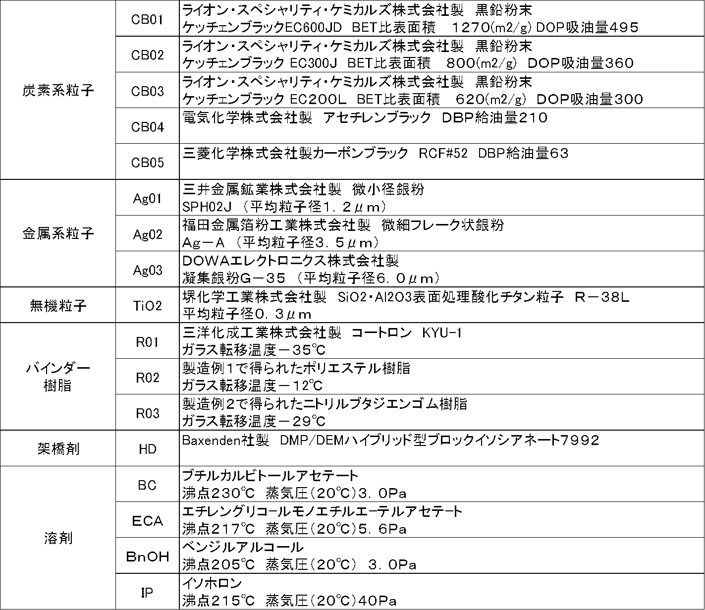
表1に示す材料を用い、表2に示される配合比にて伸縮性導電ペーストを調整した。まず、所定の溶剤量の半分量の溶剤にバインダー樹脂を溶解し、得られた溶液に金属系粒子、炭素系粒子、そのほかの成分を添加して予備混合の後、三本ロールミルにて分散することによりペースト化した。得られたペーストを表2に示す条件にて乾燥し、評価を行った。結果を表2に示す。
以下同様に表1に示す材料を用い、配合成分を替えて表2に示す導電ペーストを得た
表2に示す組成により、電極保護層用のカーボンペーストを調整した。
表2に示す組成により、伸縮性絶縁インクを調整した。
厚さ125μmの離型PETフィルムに、まず電極表面層となるカーボンペーストを用いて図1のパターンを印刷し、乾燥硬化した。次いでカバーコート層となる伸縮性絶縁樹脂インクを用い図2のパターンを重ね印刷し、乾燥硬化した。次いで伸縮性導体ペーストを用いて図3のパターンを重ね印刷し、最後に下地層となる図4のパターンを伸縮性絶縁ペーストを用いて印刷した。
次いで、図4のパターンと同一形状に打ち抜いたホットメルトシートを重ね圧着することにより、転写性の印刷配線シートを得た。
得られた転写性の印刷配線シートを裏返したスポーツシャツの所定部分に重ね、ホットプレスして印刷物を離型PETフィルムからスポーツシャツに転写し、電気配線付きスポーツシャツを得た。
ステンレススチール製ホックを介して、ユニオンツール社製の心拍センサWHS-2を接続し、同心拍センサWHS-2専用のアプリ「myBeat」を組み込んだアップル社製スマートホンで心拍データを受信し、画面表示できるように設定した。以上のようにして心拍計測機能を組み込んだスポーツシャツを作製した。
本シャツを被験者に着用させ、安静時、歩行時、ランニング時、自転車走行時、自動車運転時、睡眠時、について心電データを取得した。得られた心電データはノイズが少なく、高解像度で、心電図としてメンタルな状態、体調、疲労度、眠気、緊張度合いなどを心拍間隔の変化、心電波形などから解析可能な品位を有していた。さらに本実施例1で得られた心拍計測機能を組み込んだスポーツシャツは機械洗濯100回後も機能を維持していた。結果を表3に示す。
導電ペーストの調整で得られた導電ペースト2、導電ペースト3を用いた他は、実施例1と同様に操作して電気配線付きスポーツシャツを得た。以下同様に評価を行った結果を表3に示す。
実施例1において、図3のパターンの代わりに図5のパターンを用いた以外は同様にして電気配線付きスポーツシャツを得た。以下同様に評価を行った結果を表3に示す。
100mm×200mmのポリエステル平織りクロスに同サイズの厚さ100μmのポリウレタンシートをホットメルト接着剤にて接着し、ポリウレタンシート面を被印刷面として、長さ180mm、線幅100μm、線間100μmの平行線50本をスクリーン印刷により印刷し、乾燥硬化した。次いで平行線の端部が露出するように、160mm×80mmのカバーコートパターンを絶縁インクを用いたスクリーン印刷により形成し、乾燥硬化して試験片とした。得られた試験片の耐洗濯試験を行った。結果を表4に示す。
以下、配線パターン、印刷厚さを変えた以外は実施例4と同様に操作し、実施例5~10、比較例2、3として線幅線間の異なる配線をスクリーン印刷にて形成し耐洗濯性を評価した。結果を表4.に示す。
[導電ペーストの調整2]
表1に示す材料を用い、表5、表6に示される配合比にて伸縮性導電ペーストを調整した。まず、所定の溶剤量の半分量の溶剤にバインダー樹脂を溶解し、得られた溶液に金属系粒子、炭素系粒子、そのほかの成分を添加して予備混合の後、三本ロールミルにて分散することによりペースト化した。得られたペーストを表5、表6に示す条件にて乾燥し、評価を行った。結果を表5、表6に示す。
厚さ125μmの離型PETフィルムに、まずカバーコート層となる参考例2にて得られた絶縁樹脂インクを所定のパターンに印刷し、乾燥硬化した。パターンは電極部の周囲をリング状にカバーするランド部と伸縮性導体から成る電気配線部をカバーする絶縁コート部に相当する。ランド部は後述する電極パターンの外周3mmを覆い、リングの幅は5mmである。絶縁コート部は幅24mmであり、伸縮性導体配線をカバーする。カバーコート層の乾燥厚さは20μmとなるように調製した。
次いで電極部分となる箇所に参考例1にて得られた伸縮性カーボンペーストを印刷し、乾燥硬化した。電極部は先に印刷されたカバーコート層のリングと同心円的に配置された直径40mmの円である。
ついで、以上の工程により得られた転写性の印刷電極配線を裏返したスポーツシャツの所定部分に重ね、120℃ホットプレスして印刷物を離型PETフィルムからスポーツシャツに転写し電気配線付きスポーツシャツを得た。
得られた電気配線付きスポーツシャツは、左右の後腋窩線上と第7肋骨との交差点に直径50mmの円形電極があり、さらに円形電極から胸部中央までのストライプ状の伸縮性導体組成物による電気配線が内側に形成されている。なお左右の電極から頸部背面中央に伸びる配線の胸部中央側はいっぺんが20mmの矩形となっており、5mmのギャップにより左右は短絡されていない。
ステンレススチール製ホックを介して、ユニオンツール社製の心拍センサWHS-2を接続し、同心拍センサWHS-2専用のアプリ「myBeat」を組み込んだアップル社製スマートホンで心拍データを受信し、画面表示できるように設定した。以上のようにして心拍計測機能を組み込んだスポーツシャツを作製した。
本シャツを被験者に着用させ、安静時、歩行時、ランニング時、自転車走行時、自動車運転時、睡眠時、について心電データを取得した。得られた心電データはノイズが少なく、高解像度で、心電図としてメンタルな状態、体調、疲労度、眠気、緊張度合いなどを心拍間隔の変化、心電波形などから解析可能な品位を有していた。
さらに本応用実施例で得られた心拍計測機能を組み込んだスポーツシャツは機械洗濯30回後も機能を維持していた。


本発明におけるウェアラブル・スマート・デバイスの手法は、人体の持つ情報、すなわち筋電位、心電位などの生体電位、体温、脈拍、血圧などの生体情報を衣服に設けたセンサなど検知するためのウェアラブル装置や、あるいは、電気的な温熱装置を組み込んだ衣服、衣服圧を測定するためのセンサを組み込んだウェアラブル装置、衣服圧を利用して身体サイズを計測するウェア、足裏の圧力を測定するための靴下型装置、フレキシブルな太陽電池モジュールをテキスタイルに集積した衣服、テント、バッグなどの配線部、関節部を有する低周波治療器、温熱療養機などの配線部、屈曲度のセンシング部などに応用可能である。かかるウェアラブル装置は、人体を対象にするのみならず、ペットや家畜などの動物、あるいは伸縮部、屈曲部などを有する機械装置にも応用可能であり、ロボット義手、ロボット義足など機械装置と人体と接続して用いるシステムの電気配線としても利用できる。また体内に埋設してしようするインプラントデバイスの配線材料としても応用可能である。
2 ファブリック(基材)
3 下地層
4 導電層
5 絶縁層(カバーコート層)
6 電極表面層(カーボン層)
7 離型フィルム
8 接着層(ホットメルト層)
11 心拍検出用電極
12 デバイス装着用電極
13 配線部
Claims (12)
- 20%伸張を10回繰り返しても導通を維持できる伸縮性導体組成物からなる伸縮性電気配線を有するウェアラブル・スマート・デバイスにおいて、該電気配線の非伸張時の線間幅が50μm以上1mm以下であり、かつ、電気配線の幅/厚さの比が1から50の範囲であることを特徴とする伸縮性電気配線を有するウェアラブル・スマート・デバイス。
- 前記電気配線の非伸張時の配線幅が50μm以上1mm未満であることを特徴とする請求項1に記載の伸縮性電気配線を有するウェアラブル・スマート・デバイス。
- 前記伸縮性電気配線の伸縮性導体組成物部分の厚さが3μm以上200μm以下の範囲であることを特徴とする請求項1または2に記載の伸縮性電気配線を有するウェアラブル・スマート・デバイス。
- 前記伸縮性電気配線の伸縮性導体組成物の非伸張時の比抵抗が1×10⁻³Ωcm以下 であることを特徴とする請求項1から3のいずれかに記載の伸縮性電気配線を有するウェアラブル・スマート・デバイス。
- 前記伸縮性導体組成物が、実質的に溶剤を含有せず、少なくとも、平均粒子径が0.5μm以上5μm以下の導電性粒子、40~85質量%、非架橋型のエラストマー、15~60質量%を含有していることを特徴とする請求項1から4のいずれかに記載の伸縮性電気配線を有するウェアラブル・スマート・デバイス。
- 前記伸縮性導体組成物が、実質的に溶剤を含有せず、少なくとも、平均粒子径が0.5μm以上5μm以下の導電性粒子、40~83質量%、非架橋型のエラストマー15~60質量%を含有していることを特徴とする請求項1から5のいずれかに記載の伸縮性電気配線を有するウェアラブル・スマート・デバイス。
- 前記伸縮性導体組成物が、実質的に溶剤を含有せず、少なくとも、平均粒子径が0.5μm以上5μm以下の導電性粒子、40~90質量%、非架橋型のエラストマー15~60質量%、BET比表面積が100~550m2/gのカーボンブラック0.5~3質量%を含有していることを特徴とする請求項1から6のいずれかに記載の伸縮性電気配線を有するウェアラブル・スマート・デバイス。
- 少なくとも、金属系導電性フィラー、非架橋のエラストマー、有機溶剤を含有してなる伸縮性導体形成用ペーストであって、前記金属系導電性フィラーの平均粒子径が0.5μm以上5μm以下であることを特徴とする伸縮性導体形成用ペースト。
- 少なくとも、金属系導電性フィラー、カーボンブラック、非架橋のエラストマー、有機溶剤を含有してなる伸縮性導体形成用ペーストであって、前記金属系導電性フィラーの平均粒子径が0.5μm以上5μm以下であり、前記カーボンブラックのDBP吸油量が100~550cm3/100gの範囲であり、カーボンブラックの配合量が金属系フィラーに対して0.5~2.0質量%であることを特徴とする請求項8に記載の伸縮性導体形成用ペースト。
- 前記伸縮性導体形成用ペーストにおいて、溶剤を除いた全成分を100質量部とした場合に、金属系導電性フィラーとカーボンブラックの合計が40~90質量部であり、非架橋型のエラストマーが10~60質量部であることを特徴とする請求項8または請求項9記載の伸縮性導体形成用ペースト。
- 前記有機溶剤の沸点が200℃以上であり、20℃における飽和蒸気圧が20Pa以下であることを特徴とする請求項8から請求項10に記載の伸縮性導体形成用ペースト。
- 請求項8から請求項11のいずれかに記載の伸縮性導体形成用ペーストを用いて、線幅1mm未満、線間1mm以下の電気配線を印刷法にて形成した後に、大気圧下にて、75℃~145℃の範囲の温度で乾燥することを特徴とする伸縮性電気配線の製造方法
Priority Applications (5)
| Application Number | Priority Date | Filing Date | Title |
|---|---|---|---|
| EP17766457.0A EP3430924A4 (en) | 2016-03-16 | 2017-03-07 | INTELLIGENT DEVICE THAT CAN BE USED |
| US16/084,859 US10959467B2 (en) | 2016-03-16 | 2017-03-07 | Wearable smart device |
| JP2018505833A JP6766869B2 (ja) | 2016-03-16 | 2017-03-07 | ウェアラブル・スマート・デバイス |
| CN201780016361.7A CN108778011B (zh) | 2016-03-16 | 2017-03-07 | 可穿戴智能装置 |
| KR1020187028262A KR102106233B1 (ko) | 2016-03-16 | 2017-03-07 | 웨어러블·스마트·디바이스 |
Applications Claiming Priority (4)
| Application Number | Priority Date | Filing Date | Title |
|---|---|---|---|
| JP2016-052397 | 2016-03-16 | ||
| JP2016052396 | 2016-03-16 | ||
| JP2016-052396 | 2016-03-16 | ||
| JP2016052397 | 2016-03-16 |
Publications (1)
| Publication Number | Publication Date |
|---|---|
| WO2017159456A1 true WO2017159456A1 (ja) | 2017-09-21 |
Family
ID=59851936
Family Applications (1)
| Application Number | Title | Priority Date | Filing Date |
|---|---|---|---|
| PCT/JP2017/009014 WO2017159456A1 (ja) | 2016-03-16 | 2017-03-07 | ウェアラブル・スマート・デバイス |
Country Status (7)
| Country | Link |
|---|---|
| US (1) | US10959467B2 (ja) |
| EP (1) | EP3430924A4 (ja) |
| JP (1) | JP6766869B2 (ja) |
| KR (1) | KR102106233B1 (ja) |
| CN (1) | CN108778011B (ja) |
| TW (1) | TWI715743B (ja) |
| WO (1) | WO2017159456A1 (ja) |
Cited By (6)
| Publication number | Priority date | Publication date | Assignee | Title |
|---|---|---|---|---|
| WO2019181931A1 (ja) * | 2018-03-19 | 2019-09-26 | 株式会社フジクラ | 伸縮性配線板及び伸縮性配線板の製造方法 |
| JP2019165049A (ja) * | 2018-03-19 | 2019-09-26 | 株式会社フジクラ | 伸縮性配線板 |
| JP2019165048A (ja) * | 2018-03-19 | 2019-09-26 | 株式会社フジクラ | 伸縮性配線板及び伸縮性配線板の製造方法 |
| JP2020142008A (ja) * | 2019-03-08 | 2020-09-10 | 富士ゼロックス株式会社 | 生体電極、及び生体信号測定装置 |
| JPWO2020084981A1 (ja) * | 2018-10-22 | 2021-04-08 | 東洋紡株式会社 | デバイス連結体の製造方法、及び、デバイス連結体 |
| KR20210048535A (ko) * | 2018-10-31 | 2021-05-03 | 미쓰이 가가쿠 가부시키가이샤 | 벤더블 배선 기판, 신축할 수 있는 배선 기판 및 그들에 의한 전자 디바이스 |
Families Citing this family (3)
| Publication number | Priority date | Publication date | Assignee | Title |
|---|---|---|---|---|
| US10869391B2 (en) * | 2016-02-12 | 2020-12-15 | Toyobo Co., Ltd. | Garment-type electronic device and method for producing same |
| JPWO2020138477A1 (ja) * | 2018-12-27 | 2020-07-02 | ||
| WO2022149766A1 (ko) * | 2021-01-11 | 2022-07-14 | 삼성전자 주식회사 | 웨어러블 전자 장치의 스트랩용 수지 조성물 및 이의 제조 방법 |
Citations (10)
| Publication number | Priority date | Publication date | Assignee | Title |
|---|---|---|---|---|
| JP3723565B2 (ja) | 2003-10-21 | 2005-12-07 | 広瀬 秀男 | 電子衣料 |
| JP2007173226A (ja) | 2005-11-28 | 2007-07-05 | Osaka Univ | ゴム材料およびゴム材料の製造方法 |
| JP2008186590A (ja) * | 2007-01-26 | 2008-08-14 | Teijin Ltd | 高熱伝導性導電性組成物、導電性ペースト、導電性接着剤 |
| JP2010153364A (ja) * | 2008-11-18 | 2010-07-08 | Tokai Rubber Ind Ltd | 導電膜、およびそれを備えたトランスデューサ、フレキシブル配線板 |
| JP2012054192A (ja) | 2010-09-03 | 2012-03-15 | Bayer Material Science Ag | 伸縮性配線を有する導電部材 |
| JP2012248399A (ja) * | 2011-05-27 | 2012-12-13 | Tokai Rubber Ind Ltd | 柔軟導電材料およびその製造方法 |
| US20140318699A1 (en) * | 2012-09-11 | 2014-10-30 | Gianluigi LONGINOTTI-BUITONI | Methods of making garments having stretchable and conductive ink |
| WO2015005204A1 (ja) * | 2013-07-08 | 2015-01-15 | 東洋紡株式会社 | 導電性ペースト |
| JP2015198103A (ja) * | 2014-03-31 | 2015-11-09 | パナソニックIpマネジメント株式会社 | 伸縮性フレキシブル基板およびその製造方法 |
| JP2017022237A (ja) * | 2015-07-09 | 2017-01-26 | 日東電工株式会社 | 配線回路基板 |
Family Cites Families (8)
| Publication number | Priority date | Publication date | Assignee | Title |
|---|---|---|---|---|
| JP2005191423A (ja) * | 2003-12-26 | 2005-07-14 | Tdk Corp | キャパシタ用電極 |
| JP4771971B2 (ja) * | 2007-02-09 | 2011-09-14 | 東海ゴム工業株式会社 | 柔軟電極およびそれを用いた電子機器 |
| JP5278038B2 (ja) * | 2008-02-26 | 2013-09-04 | 日本精工株式会社 | エラストマートランスデューサー |
| JP5432513B2 (ja) | 2008-12-18 | 2014-03-05 | 旭化成せんい株式会社 | 生体信号測定装置 |
| US7862342B2 (en) * | 2009-03-18 | 2011-01-04 | Eaton Corporation | Electrical interfaces including a nano-particle layer |
| WO2011145411A1 (ja) * | 2010-05-19 | 2011-11-24 | 東海ゴム工業株式会社 | 導電膜、およびそれを用いたトランスデューサ、フレキシブル配線板 |
| JP5894813B2 (ja) * | 2012-02-10 | 2016-03-30 | 日東電工株式会社 | 導電性基板、集電体シート、燃料電池、導電性基板の製造方法および集電体シートの製造方法 |
| EP2924695A4 (en) | 2012-11-21 | 2016-01-27 | Sumitomo Riko Co Ltd | FLEXIBLE CONDUCTIVE ELEMENT AND CONVERTER THEREFORE |
-
2017
- 2017-03-07 EP EP17766457.0A patent/EP3430924A4/en not_active Withdrawn
- 2017-03-07 WO PCT/JP2017/009014 patent/WO2017159456A1/ja active Application Filing
- 2017-03-07 US US16/084,859 patent/US10959467B2/en active Active
- 2017-03-07 JP JP2018505833A patent/JP6766869B2/ja active Active
- 2017-03-07 CN CN201780016361.7A patent/CN108778011B/zh not_active Expired - Fee Related
- 2017-03-07 KR KR1020187028262A patent/KR102106233B1/ko active IP Right Grant
- 2017-03-14 TW TW106108245A patent/TWI715743B/zh active
Patent Citations (10)
| Publication number | Priority date | Publication date | Assignee | Title |
|---|---|---|---|---|
| JP3723565B2 (ja) | 2003-10-21 | 2005-12-07 | 広瀬 秀男 | 電子衣料 |
| JP2007173226A (ja) | 2005-11-28 | 2007-07-05 | Osaka Univ | ゴム材料およびゴム材料の製造方法 |
| JP2008186590A (ja) * | 2007-01-26 | 2008-08-14 | Teijin Ltd | 高熱伝導性導電性組成物、導電性ペースト、導電性接着剤 |
| JP2010153364A (ja) * | 2008-11-18 | 2010-07-08 | Tokai Rubber Ind Ltd | 導電膜、およびそれを備えたトランスデューサ、フレキシブル配線板 |
| JP2012054192A (ja) | 2010-09-03 | 2012-03-15 | Bayer Material Science Ag | 伸縮性配線を有する導電部材 |
| JP2012248399A (ja) * | 2011-05-27 | 2012-12-13 | Tokai Rubber Ind Ltd | 柔軟導電材料およびその製造方法 |
| US20140318699A1 (en) * | 2012-09-11 | 2014-10-30 | Gianluigi LONGINOTTI-BUITONI | Methods of making garments having stretchable and conductive ink |
| WO2015005204A1 (ja) * | 2013-07-08 | 2015-01-15 | 東洋紡株式会社 | 導電性ペースト |
| JP2015198103A (ja) * | 2014-03-31 | 2015-11-09 | パナソニックIpマネジメント株式会社 | 伸縮性フレキシブル基板およびその製造方法 |
| JP2017022237A (ja) * | 2015-07-09 | 2017-01-26 | 日東電工株式会社 | 配線回路基板 |
Non-Patent Citations (3)
| Title |
|---|
| JONG-HYUN AHN; JUNG HO JE: "Stretchable electronics:materials,architectures and integrations", J.PHYS.D:APPL.PHYS., vol. 45, 2012, pages 103001, XP020219041, DOI: doi:10.1088/0022-3727/45/10/103001 |
| KYOUNG-YONG CHUN; YOUNGSEOK OH; JONGHYUN RHO; JONG-HYUN AHN; YOUNG-JIN KIM; HYOUNG RYEOL CHOI; SEUNGHYUN BAIK: "Highly conductive,printable and stretchable composite films of carbon nanotubes and silver", NATURE NANOTECHNOLOGY, vol. 5, 2010, pages 853, XP055054367, DOI: doi:10.1038/nnano.2010.232 |
| See also references of EP3430924A4 |
Cited By (16)
| Publication number | Priority date | Publication date | Assignee | Title |
|---|---|---|---|---|
| US11337304B2 (en) | 2018-03-19 | 2022-05-17 | Fujikura Ltd. | Stretchable wiring board and method for manufacturing stretchable wiring board |
| JP2019165049A (ja) * | 2018-03-19 | 2019-09-26 | 株式会社フジクラ | 伸縮性配線板 |
| JP2019165048A (ja) * | 2018-03-19 | 2019-09-26 | 株式会社フジクラ | 伸縮性配線板及び伸縮性配線板の製造方法 |
| CN111418271A (zh) * | 2018-03-19 | 2020-07-14 | 株式会社藤仓 | 伸缩性配线板及伸缩性配线板的制造方法 |
| WO2019181931A1 (ja) * | 2018-03-19 | 2019-09-26 | 株式会社フジクラ | 伸縮性配線板及び伸縮性配線板の製造方法 |
| TWI703959B (zh) * | 2018-03-19 | 2020-09-11 | 日商藤倉股份有限公司 | 拉伸性配線板以及拉伸性配線板之製造方法 |
| CN111418271B (zh) * | 2018-03-19 | 2022-11-01 | 株式会社藤仓 | 伸缩性配线板及伸缩性配线板的制造方法 |
| JP7144163B2 (ja) | 2018-03-19 | 2022-09-29 | 株式会社フジクラ | 伸縮性配線板 |
| JPWO2020084981A1 (ja) * | 2018-10-22 | 2021-04-08 | 東洋紡株式会社 | デバイス連結体の製造方法、及び、デバイス連結体 |
| US11542377B2 (en) | 2018-10-31 | 2023-01-03 | Mitsui Chemicals, Inc. | Bendable circuit board, expandable circuit board, and electronic device made therefrom |
| JPWO2020090634A1 (ja) * | 2018-10-31 | 2021-05-13 | 三井化学株式会社 | ベンダブル配線基板、伸縮できる配線基板およびそれらによる電子デバイス |
| KR20210048535A (ko) * | 2018-10-31 | 2021-05-03 | 미쓰이 가가쿠 가부시키가이샤 | 벤더블 배선 기판, 신축할 수 있는 배선 기판 및 그들에 의한 전자 디바이스 |
| KR102612177B1 (ko) | 2018-10-31 | 2023-12-08 | 미쓰이 가가쿠 가부시키가이샤 | 벤더블 배선 기판, 신축할 수 있는 배선 기판 및 그들에 의한 전자 디바이스 |
| JP7396999B2 (ja) | 2018-10-31 | 2023-12-12 | 三井化学株式会社 | ベンダブル配線基板、伸縮できる配線基板およびそれらによる電子デバイス |
| JP2020142008A (ja) * | 2019-03-08 | 2020-09-10 | 富士ゼロックス株式会社 | 生体電極、及び生体信号測定装置 |
| JP7207027B2 (ja) | 2019-03-08 | 2023-01-18 | 富士フイルムビジネスイノベーション株式会社 | 生体電極、及び生体信号測定装置 |
Also Published As
| Publication number | Publication date |
|---|---|
| TW201804922A (zh) | 2018-02-16 |
| CN108778011A (zh) | 2018-11-09 |
| EP3430924A1 (en) | 2019-01-23 |
| JP6766869B2 (ja) | 2020-10-14 |
| EP3430924A4 (en) | 2019-11-20 |
| US20190053546A1 (en) | 2019-02-21 |
| TWI715743B (zh) | 2021-01-11 |
| KR20180120726A (ko) | 2018-11-06 |
| KR102106233B1 (ko) | 2020-04-29 |
| US10959467B2 (en) | 2021-03-30 |
| CN108778011B (zh) | 2021-02-12 |
| JPWO2017159456A1 (ja) | 2019-01-17 |
Similar Documents
| Publication | Publication Date | Title |
|---|---|---|
| US11357104B2 (en) | Garment-type electronic device and method for producing same | |
| WO2017159456A1 (ja) | ウェアラブル・スマート・デバイス | |
| KR102562579B1 (ko) | 신축성 도체 조성물, 신축성 도체 형성용 페이스트, 신축성 도체 조성물로 이루어지는 배선을 갖는 의복 및 그의 제조 방법 | |
| JP6624328B2 (ja) | 伸縮性電極シートの製造方法、伸縮性複合電極シートの製造方法、生体情報計測用インターフェスの製造方法 | |
| WO2018074402A1 (ja) | 伸縮性導体シート、伸縮性配線、伸縮性配線付き布帛、および導電性回復方法 | |
| JP6926500B2 (ja) | 衣服型電子機器 | |
| JP2017144239A (ja) | 衣服型電子機器 |
Legal Events
| Date | Code | Title | Description |
|---|---|---|---|
| WWE | Wipo information: entry into national phase |
Ref document number: 2018505833 Country of ref document: JP |
|
| NENP | Non-entry into the national phase |
Ref country code: DE |
|
| ENP | Entry into the national phase |
Ref document number: 20187028262 Country of ref document: KR Kind code of ref document: A |
|
| WWE | Wipo information: entry into national phase |
Ref document number: 2017766457 Country of ref document: EP |
|
| ENP | Entry into the national phase |
Ref document number: 2017766457 Country of ref document: EP Effective date: 20181016 |
|
| 121 | Ep: the epo has been informed by wipo that ep was designated in this application |
Ref document number: 17766457 Country of ref document: EP Kind code of ref document: A1 |