WO2017159071A1 - ガスバリアフィルム - Google Patents
ガスバリアフィルム Download PDFInfo
- Publication number
- WO2017159071A1 WO2017159071A1 PCT/JP2017/002976 JP2017002976W WO2017159071A1 WO 2017159071 A1 WO2017159071 A1 WO 2017159071A1 JP 2017002976 W JP2017002976 W JP 2017002976W WO 2017159071 A1 WO2017159071 A1 WO 2017159071A1
- Authority
- WO
- WIPO (PCT)
- Prior art keywords
- gas barrier
- layer
- support
- barrier film
- meth
- Prior art date
- Legal status (The legal status is an assumption and is not a legal conclusion. Google has not performed a legal analysis and makes no representation as to the accuracy of the status listed.)
- Ceased
Links
Images


Classifications
-
- B—PERFORMING OPERATIONS; TRANSPORTING
- B32—LAYERED PRODUCTS
- B32B—LAYERED PRODUCTS, i.e. PRODUCTS BUILT-UP OF STRATA OF FLAT OR NON-FLAT, e.g. CELLULAR OR HONEYCOMB, FORM
- B32B27/00—Layered products comprising a layer of synthetic resin
- B32B27/32—Layered products comprising a layer of synthetic resin comprising polyolefins
- B32B27/325—Layered products comprising a layer of synthetic resin comprising polyolefins comprising polycycloolefins
-
- B—PERFORMING OPERATIONS; TRANSPORTING
- B32—LAYERED PRODUCTS
- B32B—LAYERED PRODUCTS, i.e. PRODUCTS BUILT-UP OF STRATA OF FLAT OR NON-FLAT, e.g. CELLULAR OR HONEYCOMB, FORM
- B32B23/00—Layered products comprising a layer of cellulosic plastic substances, i.e. substances obtained by chemical modification of cellulose, e.g. cellulose ethers, cellulose esters, viscose
- B32B23/04—Layered products comprising a layer of cellulosic plastic substances, i.e. substances obtained by chemical modification of cellulose, e.g. cellulose ethers, cellulose esters, viscose comprising such cellulosic plastic substance as the main or only constituent of a layer, which is next to another layer of the same or of a different material
- B32B23/08—Layered products comprising a layer of cellulosic plastic substances, i.e. substances obtained by chemical modification of cellulose, e.g. cellulose ethers, cellulose esters, viscose comprising such cellulosic plastic substance as the main or only constituent of a layer, which is next to another layer of the same or of a different material of synthetic resin
-
- B—PERFORMING OPERATIONS; TRANSPORTING
- B32—LAYERED PRODUCTS
- B32B—LAYERED PRODUCTS, i.e. PRODUCTS BUILT-UP OF STRATA OF FLAT OR NON-FLAT, e.g. CELLULAR OR HONEYCOMB, FORM
- B32B27/00—Layered products comprising a layer of synthetic resin
- B32B27/06—Layered products comprising a layer of synthetic resin as the main or only constituent of a layer, which is next to another layer of the same or of a different material
- B32B27/08—Layered products comprising a layer of synthetic resin as the main or only constituent of a layer, which is next to another layer of the same or of a different material of synthetic resin
-
- B—PERFORMING OPERATIONS; TRANSPORTING
- B32—LAYERED PRODUCTS
- B32B—LAYERED PRODUCTS, i.e. PRODUCTS BUILT-UP OF STRATA OF FLAT OR NON-FLAT, e.g. CELLULAR OR HONEYCOMB, FORM
- B32B27/00—Layered products comprising a layer of synthetic resin
- B32B27/28—Layered products comprising a layer of synthetic resin comprising synthetic resins not wholly covered by any one of the sub-groups B32B27/30 - B32B27/42
- B32B27/281—Layered products comprising a layer of synthetic resin comprising synthetic resins not wholly covered by any one of the sub-groups B32B27/30 - B32B27/42 comprising polyimides
-
- B—PERFORMING OPERATIONS; TRANSPORTING
- B32—LAYERED PRODUCTS
- B32B—LAYERED PRODUCTS, i.e. PRODUCTS BUILT-UP OF STRATA OF FLAT OR NON-FLAT, e.g. CELLULAR OR HONEYCOMB, FORM
- B32B27/00—Layered products comprising a layer of synthetic resin
- B32B27/30—Layered products comprising a layer of synthetic resin comprising vinyl (co)polymers; comprising acrylic (co)polymers
-
- B—PERFORMING OPERATIONS; TRANSPORTING
- B32—LAYERED PRODUCTS
- B32B—LAYERED PRODUCTS, i.e. PRODUCTS BUILT-UP OF STRATA OF FLAT OR NON-FLAT, e.g. CELLULAR OR HONEYCOMB, FORM
- B32B27/00—Layered products comprising a layer of synthetic resin
- B32B27/30—Layered products comprising a layer of synthetic resin comprising vinyl (co)polymers; comprising acrylic (co)polymers
- B32B27/302—Layered products comprising a layer of synthetic resin comprising vinyl (co)polymers; comprising acrylic (co)polymers comprising aromatic vinyl (co)polymers, e.g. styrenic (co)polymers
-
- B—PERFORMING OPERATIONS; TRANSPORTING
- B32—LAYERED PRODUCTS
- B32B—LAYERED PRODUCTS, i.e. PRODUCTS BUILT-UP OF STRATA OF FLAT OR NON-FLAT, e.g. CELLULAR OR HONEYCOMB, FORM
- B32B27/00—Layered products comprising a layer of synthetic resin
- B32B27/30—Layered products comprising a layer of synthetic resin comprising vinyl (co)polymers; comprising acrylic (co)polymers
- B32B27/304—Layered products comprising a layer of synthetic resin comprising vinyl (co)polymers; comprising acrylic (co)polymers comprising vinyl halide (co)polymers, e.g. PVC, PVDC, PVF, PVDF
-
- B—PERFORMING OPERATIONS; TRANSPORTING
- B32—LAYERED PRODUCTS
- B32B—LAYERED PRODUCTS, i.e. PRODUCTS BUILT-UP OF STRATA OF FLAT OR NON-FLAT, e.g. CELLULAR OR HONEYCOMB, FORM
- B32B27/00—Layered products comprising a layer of synthetic resin
- B32B27/30—Layered products comprising a layer of synthetic resin comprising vinyl (co)polymers; comprising acrylic (co)polymers
- B32B27/306—Layered products comprising a layer of synthetic resin comprising vinyl (co)polymers; comprising acrylic (co)polymers comprising vinyl acetate or vinyl alcohol (co)polymers
-
- B—PERFORMING OPERATIONS; TRANSPORTING
- B32—LAYERED PRODUCTS
- B32B—LAYERED PRODUCTS, i.e. PRODUCTS BUILT-UP OF STRATA OF FLAT OR NON-FLAT, e.g. CELLULAR OR HONEYCOMB, FORM
- B32B27/00—Layered products comprising a layer of synthetic resin
- B32B27/30—Layered products comprising a layer of synthetic resin comprising vinyl (co)polymers; comprising acrylic (co)polymers
- B32B27/308—Layered products comprising a layer of synthetic resin comprising vinyl (co)polymers; comprising acrylic (co)polymers comprising acrylic (co)polymers
-
- B—PERFORMING OPERATIONS; TRANSPORTING
- B32—LAYERED PRODUCTS
- B32B—LAYERED PRODUCTS, i.e. PRODUCTS BUILT-UP OF STRATA OF FLAT OR NON-FLAT, e.g. CELLULAR OR HONEYCOMB, FORM
- B32B27/00—Layered products comprising a layer of synthetic resin
- B32B27/32—Layered products comprising a layer of synthetic resin comprising polyolefins
-
- B—PERFORMING OPERATIONS; TRANSPORTING
- B32—LAYERED PRODUCTS
- B32B—LAYERED PRODUCTS, i.e. PRODUCTS BUILT-UP OF STRATA OF FLAT OR NON-FLAT, e.g. CELLULAR OR HONEYCOMB, FORM
- B32B27/00—Layered products comprising a layer of synthetic resin
- B32B27/34—Layered products comprising a layer of synthetic resin comprising polyamides
-
- B—PERFORMING OPERATIONS; TRANSPORTING
- B32—LAYERED PRODUCTS
- B32B—LAYERED PRODUCTS, i.e. PRODUCTS BUILT-UP OF STRATA OF FLAT OR NON-FLAT, e.g. CELLULAR OR HONEYCOMB, FORM
- B32B27/00—Layered products comprising a layer of synthetic resin
- B32B27/36—Layered products comprising a layer of synthetic resin comprising polyesters
-
- B—PERFORMING OPERATIONS; TRANSPORTING
- B32—LAYERED PRODUCTS
- B32B—LAYERED PRODUCTS, i.e. PRODUCTS BUILT-UP OF STRATA OF FLAT OR NON-FLAT, e.g. CELLULAR OR HONEYCOMB, FORM
- B32B27/00—Layered products comprising a layer of synthetic resin
- B32B27/36—Layered products comprising a layer of synthetic resin comprising polyesters
- B32B27/365—Layered products comprising a layer of synthetic resin comprising polyesters comprising polycarbonates
-
- B—PERFORMING OPERATIONS; TRANSPORTING
- B32—LAYERED PRODUCTS
- B32B—LAYERED PRODUCTS, i.e. PRODUCTS BUILT-UP OF STRATA OF FLAT OR NON-FLAT, e.g. CELLULAR OR HONEYCOMB, FORM
- B32B5/00—Layered products characterised by the non- homogeneity or physical structure, i.e. comprising a fibrous, filamentary, particulate or foam layer; Layered products characterised by having a layer differing constitutionally or physically in different parts
- B32B5/16—Layered products characterised by the non- homogeneity or physical structure, i.e. comprising a fibrous, filamentary, particulate or foam layer; Layered products characterised by having a layer differing constitutionally or physically in different parts characterised by features of a layer formed of particles, e.g. chips, powder or granules
-
- B—PERFORMING OPERATIONS; TRANSPORTING
- B32—LAYERED PRODUCTS
- B32B—LAYERED PRODUCTS, i.e. PRODUCTS BUILT-UP OF STRATA OF FLAT OR NON-FLAT, e.g. CELLULAR OR HONEYCOMB, FORM
- B32B7/00—Layered products characterised by the relation between layers; Layered products characterised by the relative orientation of features between layers, or by the relative values of a measurable parameter between layers, i.e. products comprising layers having different physical, chemical or physicochemical properties; Layered products characterised by the interconnection of layers
- B32B7/04—Interconnection of layers
- B32B7/12—Interconnection of layers using interposed adhesives or interposed materials with bonding properties
-
- B—PERFORMING OPERATIONS; TRANSPORTING
- B32—LAYERED PRODUCTS
- B32B—LAYERED PRODUCTS, i.e. PRODUCTS BUILT-UP OF STRATA OF FLAT OR NON-FLAT, e.g. CELLULAR OR HONEYCOMB, FORM
- B32B9/00—Layered products comprising a layer of a particular substance not covered by groups B32B11/00 - B32B29/00
-
- B—PERFORMING OPERATIONS; TRANSPORTING
- B32—LAYERED PRODUCTS
- B32B—LAYERED PRODUCTS, i.e. PRODUCTS BUILT-UP OF STRATA OF FLAT OR NON-FLAT, e.g. CELLULAR OR HONEYCOMB, FORM
- B32B9/00—Layered products comprising a layer of a particular substance not covered by groups B32B11/00 - B32B29/00
- B32B9/04—Layered products comprising a layer of a particular substance not covered by groups B32B11/00 - B32B29/00 comprising such particular substance as the main or only constituent of a layer, which is next to another layer of the same or of a different material
- B32B9/045—Layered products comprising a layer of a particular substance not covered by groups B32B11/00 - B32B29/00 comprising such particular substance as the main or only constituent of a layer, which is next to another layer of the same or of a different material of synthetic resin
-
- H—ELECTRICITY
- H05—ELECTRIC TECHNIQUES NOT OTHERWISE PROVIDED FOR
- H05B—ELECTRIC HEATING; ELECTRIC LIGHT SOURCES NOT OTHERWISE PROVIDED FOR; CIRCUIT ARRANGEMENTS FOR ELECTRIC LIGHT SOURCES, IN GENERAL
- H05B33/00—Electroluminescent light sources
- H05B33/02—Details
- H05B33/04—Sealing arrangements, e.g. against humidity
-
- B—PERFORMING OPERATIONS; TRANSPORTING
- B32—LAYERED PRODUCTS
- B32B—LAYERED PRODUCTS, i.e. PRODUCTS BUILT-UP OF STRATA OF FLAT OR NON-FLAT, e.g. CELLULAR OR HONEYCOMB, FORM
- B32B2250/00—Layers arrangement
- B32B2250/02—2 layers
-
- B—PERFORMING OPERATIONS; TRANSPORTING
- B32—LAYERED PRODUCTS
- B32B—LAYERED PRODUCTS, i.e. PRODUCTS BUILT-UP OF STRATA OF FLAT OR NON-FLAT, e.g. CELLULAR OR HONEYCOMB, FORM
- B32B2250/00—Layers arrangement
- B32B2250/24—All layers being polymeric
- B32B2250/242—All polymers belonging to those covered by group B32B27/32
-
- B—PERFORMING OPERATIONS; TRANSPORTING
- B32—LAYERED PRODUCTS
- B32B—LAYERED PRODUCTS, i.e. PRODUCTS BUILT-UP OF STRATA OF FLAT OR NON-FLAT, e.g. CELLULAR OR HONEYCOMB, FORM
- B32B2255/00—Coating on the layer surface
- B32B2255/10—Coating on the layer surface on synthetic resin layer or on natural or synthetic rubber layer
-
- B—PERFORMING OPERATIONS; TRANSPORTING
- B32—LAYERED PRODUCTS
- B32B—LAYERED PRODUCTS, i.e. PRODUCTS BUILT-UP OF STRATA OF FLAT OR NON-FLAT, e.g. CELLULAR OR HONEYCOMB, FORM
- B32B2255/00—Coating on the layer surface
- B32B2255/20—Inorganic coating
-
- B—PERFORMING OPERATIONS; TRANSPORTING
- B32—LAYERED PRODUCTS
- B32B—LAYERED PRODUCTS, i.e. PRODUCTS BUILT-UP OF STRATA OF FLAT OR NON-FLAT, e.g. CELLULAR OR HONEYCOMB, FORM
- B32B2255/00—Coating on the layer surface
- B32B2255/26—Polymeric coating
-
- B—PERFORMING OPERATIONS; TRANSPORTING
- B32—LAYERED PRODUCTS
- B32B—LAYERED PRODUCTS, i.e. PRODUCTS BUILT-UP OF STRATA OF FLAT OR NON-FLAT, e.g. CELLULAR OR HONEYCOMB, FORM
- B32B2255/00—Coating on the layer surface
- B32B2255/28—Multiple coating on one surface
-
- B—PERFORMING OPERATIONS; TRANSPORTING
- B32—LAYERED PRODUCTS
- B32B—LAYERED PRODUCTS, i.e. PRODUCTS BUILT-UP OF STRATA OF FLAT OR NON-FLAT, e.g. CELLULAR OR HONEYCOMB, FORM
- B32B2264/00—Composition or properties of particles which form a particulate layer or are present as additives
- B32B2264/02—Synthetic macromolecular particles
- B32B2264/0214—Particles made of materials belonging to B32B27/00
- B32B2264/025—Acrylic resin particles, e.g. polymethyl methacrylate or ethylene-acrylate copolymers
-
- B—PERFORMING OPERATIONS; TRANSPORTING
- B32—LAYERED PRODUCTS
- B32B—LAYERED PRODUCTS, i.e. PRODUCTS BUILT-UP OF STRATA OF FLAT OR NON-FLAT, e.g. CELLULAR OR HONEYCOMB, FORM
- B32B2307/00—Properties of the layers or laminate
- B32B2307/30—Properties of the layers or laminate having particular thermal properties
-
- B—PERFORMING OPERATIONS; TRANSPORTING
- B32—LAYERED PRODUCTS
- B32B—LAYERED PRODUCTS, i.e. PRODUCTS BUILT-UP OF STRATA OF FLAT OR NON-FLAT, e.g. CELLULAR OR HONEYCOMB, FORM
- B32B2307/00—Properties of the layers or laminate
- B32B2307/40—Properties of the layers or laminate having particular optical properties
-
- B—PERFORMING OPERATIONS; TRANSPORTING
- B32—LAYERED PRODUCTS
- B32B—LAYERED PRODUCTS, i.e. PRODUCTS BUILT-UP OF STRATA OF FLAT OR NON-FLAT, e.g. CELLULAR OR HONEYCOMB, FORM
- B32B2307/00—Properties of the layers or laminate
- B32B2307/40—Properties of the layers or laminate having particular optical properties
- B32B2307/412—Transparent
-
- B—PERFORMING OPERATIONS; TRANSPORTING
- B32—LAYERED PRODUCTS
- B32B—LAYERED PRODUCTS, i.e. PRODUCTS BUILT-UP OF STRATA OF FLAT OR NON-FLAT, e.g. CELLULAR OR HONEYCOMB, FORM
- B32B2307/00—Properties of the layers or laminate
- B32B2307/50—Properties of the layers or laminate having particular mechanical properties
- B32B2307/536—Hardness
-
- B—PERFORMING OPERATIONS; TRANSPORTING
- B32—LAYERED PRODUCTS
- B32B—LAYERED PRODUCTS, i.e. PRODUCTS BUILT-UP OF STRATA OF FLAT OR NON-FLAT, e.g. CELLULAR OR HONEYCOMB, FORM
- B32B2307/00—Properties of the layers or laminate
- B32B2307/70—Other properties
- B32B2307/724—Permeability to gases, adsorption
- B32B2307/7242—Non-permeable
- B32B2307/7244—Oxygen barrier
-
- B—PERFORMING OPERATIONS; TRANSPORTING
- B32—LAYERED PRODUCTS
- B32B—LAYERED PRODUCTS, i.e. PRODUCTS BUILT-UP OF STRATA OF FLAT OR NON-FLAT, e.g. CELLULAR OR HONEYCOMB, FORM
- B32B2307/00—Properties of the layers or laminate
- B32B2307/70—Other properties
- B32B2307/724—Permeability to gases, adsorption
- B32B2307/7242—Non-permeable
- B32B2307/7246—Water vapor barrier
-
- B—PERFORMING OPERATIONS; TRANSPORTING
- B32—LAYERED PRODUCTS
- B32B—LAYERED PRODUCTS, i.e. PRODUCTS BUILT-UP OF STRATA OF FLAT OR NON-FLAT, e.g. CELLULAR OR HONEYCOMB, FORM
- B32B2307/00—Properties of the layers or laminate
- B32B2307/70—Other properties
- B32B2307/732—Dimensional properties
-
- B—PERFORMING OPERATIONS; TRANSPORTING
- B32—LAYERED PRODUCTS
- B32B—LAYERED PRODUCTS, i.e. PRODUCTS BUILT-UP OF STRATA OF FLAT OR NON-FLAT, e.g. CELLULAR OR HONEYCOMB, FORM
- B32B2457/00—Electrical equipment
- B32B2457/12—Photovoltaic modules
-
- B—PERFORMING OPERATIONS; TRANSPORTING
- B32—LAYERED PRODUCTS
- B32B—LAYERED PRODUCTS, i.e. PRODUCTS BUILT-UP OF STRATA OF FLAT OR NON-FLAT, e.g. CELLULAR OR HONEYCOMB, FORM
- B32B2457/00—Electrical equipment
- B32B2457/20—Displays, e.g. liquid crystal displays, plasma displays
-
- B—PERFORMING OPERATIONS; TRANSPORTING
- B32—LAYERED PRODUCTS
- B32B—LAYERED PRODUCTS, i.e. PRODUCTS BUILT-UP OF STRATA OF FLAT OR NON-FLAT, e.g. CELLULAR OR HONEYCOMB, FORM
- B32B2457/00—Electrical equipment
- B32B2457/20—Displays, e.g. liquid crystal displays, plasma displays
- B32B2457/202—LCD, i.e. liquid crystal displays
-
- B—PERFORMING OPERATIONS; TRANSPORTING
- B32—LAYERED PRODUCTS
- B32B—LAYERED PRODUCTS, i.e. PRODUCTS BUILT-UP OF STRATA OF FLAT OR NON-FLAT, e.g. CELLULAR OR HONEYCOMB, FORM
- B32B2457/00—Electrical equipment
- B32B2457/20—Displays, e.g. liquid crystal displays, plasma displays
- B32B2457/206—Organic displays, e.g. OLED
-
- B—PERFORMING OPERATIONS; TRANSPORTING
- B32—LAYERED PRODUCTS
- B32B—LAYERED PRODUCTS, i.e. PRODUCTS BUILT-UP OF STRATA OF FLAT OR NON-FLAT, e.g. CELLULAR OR HONEYCOMB, FORM
- B32B2571/00—Protective equipment
-
- H—ELECTRICITY
- H10—SEMICONDUCTOR DEVICES; ELECTRIC SOLID-STATE DEVICES NOT OTHERWISE PROVIDED FOR
- H10K—ORGANIC ELECTRIC SOLID-STATE DEVICES
- H10K2102/00—Constructional details relating to the organic devices covered by this subclass
- H10K2102/301—Details of OLEDs
- H10K2102/331—Nanoparticles used in non-emissive layers, e.g. in packaging layer
-
- H—ELECTRICITY
- H10—SEMICONDUCTOR DEVICES; ELECTRIC SOLID-STATE DEVICES NOT OTHERWISE PROVIDED FOR
- H10K—ORGANIC ELECTRIC SOLID-STATE DEVICES
- H10K50/00—Organic light-emitting devices
- H10K50/80—Constructional details
- H10K50/84—Passivation; Containers; Encapsulations
- H10K50/844—Encapsulations
- H10K50/8445—Encapsulations multilayered coatings having a repetitive structure, e.g. having multiple organic-inorganic bilayers
Definitions
- the present invention relates to a gas barrier film having an inorganic layer as a gas barrier layer and exhibiting high gas barrier properties.
- Gas barrier films that block moisture and oxygen are used for the purpose of protecting various members and materials.
- organic electroluminescence element organic EL element
- plastic liquid crystal these are sealed with a gas barrier film in order to protect the organic EL element or plastic liquid crystal.
- a gas barrier film in order to protect the organic EL element or plastic liquid crystal.
- the photovoltaic cell which has a photoelectric converting layer etc. is weak to a water
- the gas barrier film usually has a structure in which a gas barrier layer that expresses gas barrier properties is formed on the surface of a resin film or the like as a support.
- a structure that exhibits high gas barrier properties an organic / inorganic laminate type gas barrier having at least one combination of an inorganic layer and an organic layer serving as an underlayer of the inorganic layer on the support as a gas barrier layer. Film is known.
- the organic / inorganic laminated gas barrier film forms an inorganic layer exhibiting gas barrier properties on an organic layer serving as a base.
- the gas barrier film is required to have good optical characteristics such as high transparency.
- a support having a low retardation value such as a resin film made of cycloolefin polymer (COP) or cycloolefin copolymer (COC) is used as the support. Is preferred.
- a protective inorganic layer for protecting a support is provided on the surface of a support having a retardation value of 300 nm or less such as a COP film or a COC film, and an inorganic layer is formed on the protective inorganic layer.
- a gas barrier film in which one or more combinations of the organic layer serving as the base layer of the inorganic layer are formed.
- Patent Document 2 as a gas barrier film using a support having a low retardation value such as a COP film, an underlayer containing a polymerizable compound containing a condensed polycyclic hydrocarbon structure is formed on the surface of the support,
- a gas barrier film is described in which an inorganic layer made of a metal nitride or a metal oxide is formed on the base layer.
- the organic layer is formed of tricyclodecane dimethanol diacrylate (manufactured by Shin-Nakamura Chemical Co., Ltd., A-DCP).
- the gas barrier film using a COP film or the like as a support does not provide the desired gas barrier property even when the organic / inorganic laminated structure is capable of obtaining a high gas barrier property. In some cases, the optical characteristics may also deteriorate.
- An object of the present invention is to solve such problems of the prior art, and even when a film having a low retardation value such as a COP film is used as a support, the target gas barrier property is stably expressed.
- the object is to provide a gas barrier film.
- the gas barrier film of the present invention comprises a support, A gas barrier layer including an inorganic layer provided on one surface of the support; A deformation-suppressing layer comprising a bifunctional or higher-functional (meth) acrylate provided on a surface opposite to the side on which the gas barrier layer of the support is provided,
- the thermal expansion coefficient of the support is 30 ⁇ 10 ⁇ 6 / ° C. or more
- the (meth) acrylate of the deformation suppressing layer provides a gas barrier film having a volume shrinkage of 3 to 20%.
- the retardation value of the support is preferably 150 nm or less.
- the (meth) acrylate of the deformation suppressing layer contains a condensed polycyclic hydrocarbon structure.
- a gas barrier layer contains the organic layer contact
- the organic layer in contact with the support contains bifunctional or higher functional (meth) acrylate, and the (meth) acrylate in the organic layer in contact with the support has a volume shrinkage of 3 to 20%.
- the difference between the volume shrinkage ratio of the (meth) acrylate of the deformation suppressing layer and the volume shrinkage ratio of the (meth) acrylate of the organic layer in contact with the support is within 15%.
- the (meth) acrylate of the organic layer in contact with the support contains a condensed polycyclic hydrocarbon structure.
- the gas barrier layer further includes one or more combinations of an inorganic layer and an organic layer serving as a base for the inorganic layer.
- a gas barrier layer has a some layer, and the layer most spaced apart from the support body of the said some layers is an organic layer.
- a protective film made of polyethylene or polypropylene is preferably provided on the surface of the gas barrier layer.
- the water vapor permeability of the support at a temperature of 40 ° C. and a humidity of 90% RH is preferably 10 g / (m 2 ⁇ day) or more.
- the thickness of the deformation suppressing layer is preferably 1 to 20% of the thickness of the support.
- the pencil hardness of the deformation suppressing layer is preferably 3B to 3H.
- transformation suppression layer contains the particle
- the particles preferably contain polymethyl (meth) acrylate or polybutyl (meth) acrylate and have a particle size of 0.01 to 10 ⁇ m.
- the inorganic layer is preferably made of a silicon compound.
- the gas barrier film of the present invention stably exhibits the target gas barrier property even when a film having a low retardation value such as a COP film is used as a support in a gas barrier film having an inorganic layer as a gas barrier layer.
- FIG. 1 an example of the gas barrier film of this invention is shown notionally.
- a gas barrier film 10 shown in FIG. 1 is provided on a support 12, an organic layer 16 provided on one surface of the support 12, an inorganic layer 18 provided on the organic layer 16, and an inorganic layer 18. It has the outermost organic layer 16 and the deformation suppressing layer 20 provided on the surface of the support 12 opposite to the side where the organic layer 16 is provided.
- the organic layer 16 is provided as a preferred embodiment.
- a gas barrier layer is formed by the organic layer 16 and the inorganic layer 18. That is, the gas barrier film 10 is the aforementioned organic / inorganic laminated type gas barrier film.
- “the surface of the support 12 opposite to the side on which the gas barrier layer is provided” is also referred to as “reverse side”.
- a gas barrier layer is formed by three layers of an organic layer 16, an inorganic layer 18, and an organic layer 16.
- the organic layer 16 below the inorganic layer 18 is the organic layer 16 in contact with the support 12 and is a base layer for the inorganic layer 18 for properly forming the inorganic layer 18. That is, the gas barrier film 10 shown in FIG. 1 has one set of a combination of the organic layer 16 and the inorganic layer 18 serving as a base.
- the organic layer in contact with the support means an organic layer formed on the surface of the support, and the organic layer in contact with the support is a support among the gas barrier layers composed of a plurality of layers. The organic layer closest to the body.
- the outermost organic layer 16, that is, the organic layer 16 farthest from the support 12 among the plurality of layers constituting the gas barrier layer is a protective layer for protecting the inorganic layer 18.
- the gas barrier layer of the gas barrier film of the present invention can use various layer configurations other than the configuration shown in FIG.
- the gas barrier film 26 shown in FIG. 2 has a combination of the organic layer 16 and the inorganic layer 18 serving as a base on the organic layer 16 and the inorganic layer 18 in contact with the support, and the organic layer 16 as the outermost layer.
- Have The structure which has two or more combinations of the organic layer 16 and the inorganic layer 18, and has the organic layer 16 in the outermost layer may be sufficient. Or the structure which remove
- the gas barrier film of this invention has high gas barrier property, so that there are many combinations of the organic layer 16 used as a foundation
- the gas barrier film of the present invention may have a configuration in which only one layer of the inorganic layer 18 is provided on the surface of the support 12 without the organic layer 16 like the gas barrier film 30 shown in FIG. That is, in the gas barrier film of the present invention, the gas barrier layer may be formed of only one inorganic layer 18. Moreover, the structure which has the inorganic layer 18 on the surface of the support body 12, and has the organic layer 16 of the outermost layer for protecting the inorganic layer 18 on it may be sufficient.
- the gas barrier film of the present invention has a gas barrier layer including at least one inorganic layer 18 on one surface of the support 12, and the surface of the support having the inorganic layer 18 (the surface of the inorganic layer 18). It is only necessary to have the predetermined deformation suppression layer 20 on the surface opposite to the (formation surface), and various layer configurations can be used.
- the support 12 is a sheet-like material that supports the gas barrier layer and the deformation suppression layer 20.
- the support 12 has a thermal expansion coefficient (linear thermal expansion coefficient) of 30 ⁇ 10 ⁇ 6 / ° C. or higher.
- the thermal expansion coefficient of the support 12 may be measured according to JIS K7197. Further, as the thermal expansion coefficient of the support 12, a value described in the catalog of the support 12 may be used.
- various sheet-like materials can be used as long as the thermal expansion coefficient is 30 ⁇ 10 ⁇ 6 / ° C. or more.
- polyethylene PE
- polyethylene naphthalate PEN
- polyamide PA
- polyethylene terephthalate PET
- polyvinyl chloride PVC
- polyvinyl alcohol PVA
- polyacrylonitrile PAN
- polyimide PI
- Transparent polyimide polymethyl methacrylate resin (PMMA), polycarbonate (PC), polyacrylate, polymethacrylate, polypropylene (PP), polystyrene (PS), ABS, cycloolefin copolymer (COC), cycloolefin polymer (COP),
- film resin film which consists of various resins, such as a triacetyl cellulose (TAC), is illustrated suitably.
- TAC triacetyl cellulose
- the support 12 preferably has a retardation value (Re value) of 150 nm or less, more preferably 60 nm or less, and particularly preferably 30 nm or less.
- Re value retardation value
- the support 12 having a retardation value of 150 nm or less it is required to have good optical properties such as sealing of the above-mentioned organic EL elements and solar cells, and further a wavelength conversion film having a quantum dot layer sandwiched between gas barrier films.
- the gas barrier film 10 that can be suitably used for the intended use can be obtained.
- a film having a low retardation value such as a PC film, a COP film, a COC film, and a TAC film is preferably used as the support 12.
- the COP film and the COC film are easy in handling, have a low hygroscopic expansion coefficient, and can suitably form the inorganic layer 18 by a gas phase volume method (vacuum film formation) described later.
- a gas phase volume method vacuum film formation
- a COP film is preferably used.
- the support 12 has various functions such as a protective layer, an adhesive layer, a light reflection layer, an antireflection layer, a light shielding layer, a planarization layer, a buffer layer, and a stress relaxation layer on the surface of such a resin film.
- a layer (film) for obtaining may be formed.
- the thickness of the support body 12 is preferably 5 to 100 ⁇ m, more preferably 10 to 50 ⁇ m.
- the thickness of the support 12 is preferably 5 to 100 ⁇ m, more preferably 10 to 50 ⁇ m.
- the support 12 having a water vapor transmission rate (WVTR) of 10 g / (m 2 ⁇ day) or more under conditions of a temperature of 40 ° C. and a humidity of 90% RH is also preferably used.
- WVTR water vapor transmission rate
- the support 12 having a water vapor transmission rate of 10 g / (m 2 ⁇ day) or more is used, the inorganic layer 18 is easily damaged due to thermal expansion of the support 12 described later.
- the gas barrier film 10 of the present invention has the deformation suppressing layer 20 on the opposite side surface of the support 12, even if the support 12 having a high water vapor transmission rate is used, the thermal expansion of the support 12.
- the organic layer 16 is formed on one surface of the support 12, the inorganic layer 18 is formed thereon, and the outermost organic layer 16 is formed thereon.
- the organic layer 16 is a layer made of an organic compound, which is provided as a preferred embodiment, and is obtained by polymerizing (crosslinking) monomers and oligomers that become the organic layer 16.
- the organic layer 16 is preferably provided on the surface of the support 12.
- the organic layer 16 in contact with the support 12 that is the lower layer of the inorganic layer 18 functions as a base layer for appropriately forming the inorganic layer 18 that mainly exhibits gas barrier properties in the gas barrier film 10.
- the organic layer 16 as the base of such an inorganic layer 18, the surface of the support 12 is embedded and foreign matter adhering to the surface of the support 12 is embedded to form the inorganic layer 18.
- the film surface can be in a state suitable for forming the inorganic layer 18. As a result, there are no portions where the inorganic compound that becomes the inorganic layer 18 is difficult to deposit, such as irregularities on the surface of the support 12 or shadows of foreign matter, and there is no gap on the entire surface of the organic layer 16 plate. 18 can be formed.
- the outermost organic layer 16 is an organic layer that acts as a protective layer for the inorganic layer 18. As described above, in the gas barrier film 10, it is the inorganic layer 18 that mainly exhibits gas barrier properties. Therefore, if the inorganic layer 18 is cracked or damaged, the gas barrier performance is reduced. On the other hand, by having the organic layer 16 as the protective layer as the outermost layer, it is possible to prevent damage to the inorganic layer 18 and to develop the target gas barrier performance over a long period of time.
- the material for forming the organic layer 16 is not limited, and various known organic compounds can be used. Specifically, polyester, (meth) acrylic resin, methacrylic acid-maleic acid copolymer, polystyrene, transparent fluororesin, polyimide, fluorinated polyimide, polyamide, polyamideimide, polyetherimide, cellulose acylate, polyurethane, poly Ether ether ketone, polycarbonate, alicyclic polyolefin, polyarylate, polyethersulfone, polysulfone, fluorene ring modified polycarbonate, alicyclic modified polycarbonate, fluorene ring modified polyester, acrylic compounds, thermoplastic resins, polysiloxane and other An organic silicon compound film is preferably exemplified.
- the organic layer 16 formed by a polymer of a radical curable compound and / or a cationic curable compound having an ether group as a functional group is preferable from the viewpoint of excellent high glass transition temperature and strength.
- DPGDA dipropylene glycol di (meth) acrylate
- TMPTA trimethylolpropane tri (meth) acrylate
- DPGDA dimethyl glycol di (meth) acrylate
- Acrylic polymers and methacrylic polymers whose main component is a polymer of an acrylate and / or methacrylate acrylate and / or methacrylate, such as pentaerythritol hexa (meth) acrylate (DPHA), which is more than trifunctional are Preferred examples of the forming material. It is also preferable to use a plurality of these acrylic polymers and methacrylic polymers.
- a (meth) acrylic polymer obtained by polymerizing an ultraviolet curable urethane acrylic polymer can also be suitably used.
- Specific examples include a graft copolymer having an acrylic polymer as a main chain and a side chain having a urethane polymer having an acryloyl group at the terminal and / or a urethane oligomer having an acryloyl group at the terminal.
- the organic layer 16 in contact with the support 12 may contain a (meth) acrylic polymer obtained by polymerizing this graft copolymer.
- This graft copolymer is highly transparent and hardly yellows.
- the organic layer 16 using this graft copolymer is particularly suitable as the outermost organic layer 16 for protecting the inorganic layer 18.
- the acrylic main chain in the graft copolymer may be formed by individually polymerizing (meth) acrylate monomer, ethyl acrylate monomer, etc., and any of these copolymers or any of these and other It may be a copolymer with a monomer.
- a copolymer obtained from (meth) acrylic acid ester and ethylene is also preferable.
- the acrylic main chain and the urethane polymer unit or the urethane oligomer unit may be directly bonded, or may be bonded via another linking group. Examples of other linking groups include ethylene oxide groups, polyethylene oxide groups, propylene oxide groups, and polypropylene oxide groups.
- the graft copolymer may contain multiple types of side chains in which urethane polymer units or urethane oligomer units are bonded via different linking groups (including direct bonds).
- the graft copolymer preferably has a weight average molecular weight of 10,000 to 3000000, more preferably 10,000 to 250,000, and particularly preferably 12,000 to 200,000. Further, this graft copolymer preferably has a double bond equivalent (acryl equivalent) of 500 g / mol or more, more preferably 550 g / mol or more, and preferably 600 g / mol or more. . Furthermore, the double bond equivalent of the graft copolymer is more preferably 2000 g / mol or less.
- the weight average molecular weight (Mw) of various polymers may be measured as a molecular weight in terms of polystyrene (PS) by gel permeation chromatography (GPC). More specifically, the weight average molecular weight is HLC-8220 (manufactured by Tosoh Corporation), TSKgel Super AWM-H (manufactured by Tosoh Corporation, 6.0 mm ID ⁇ 15.0 cm) as a column, and 10 mmol / L as an eluent. It may be obtained by using a lithium bromide NMP (N-methylpyrrolidinone) solution. As the weight average molecular weight of the polymer or the like, a numerical value described in a catalog or the like may be used. Moreover, what is necessary is just to measure a double bond equivalent by a well-known method.
- HLC-8220 manufactured by Tosoh Corporation
- TSKgel Super AWM-H manufactured by Tosoh Corporation, 6.0 mm ID ⁇ 15.0 cm
- a graft copolymer for example, a commercially available product such as an ultraviolet curable urethane acrylic polymer (Acryt 8BR series) manufactured by Taisei Fine Chemical Co., Ltd. may be used. A plurality of graft copolymers may be used in combination.
- the organic layer 16 is preferably formed on the surface of the support 12.
- the organic layer 16 on the surface of the support 12 is formed by using a bifunctional or higher functional (meth) acrylate having a volume shrinkage of 3 to 20%, similar to the deformation suppressing layer 20 described later.
- the organic layer 16 preferably contains a bifunctional or higher functional (meth) acrylate polymer having a volume shrinkage of 3 to 20%.
- the (meth) acrylate containing the condensed polycyclic hydrocarbon structure similar to the deformation suppression layer 20 is suitably used as the organic layer 16 on the surface of the support 12.
- the difference in volume shrinkage with the (meth) acrylate used in the deformation suppressing layer 20 is 15% or less, and (meth) acrylate is suitably used as the organic layer 16 on the surface of the support 12.
- the same (meth) acrylate as the deformation suppression layer 20 is suitably used as the organic layer 16 on the surface of the support 12, and among them, the same organic layer as the deformation suppression layer 20 is on the surface of the support 12.
- the organic layer 16 is more preferably used.
- the organic layer 16 formed on the surface of the support 12 as such an organic layer, it is possible to more suitably prevent deterioration of gas barrier properties and deterioration of optical characteristics due to thermal expansion of the support 12 described later. It is preferable in that it can be performed.
- the organic layer 16 formed on the surface of the support 12 is composed of a bifunctional or higher functional (meth) acrylate having a volume shrinkage of 3 to 20%, a (meth) acrylate such as TMPTA and / or the above-mentioned.
- a bifunctional or higher functional (meth) acrylate having a volume shrinkage of 3 to 20%
- a (meth) acrylate such as TMPTA and / or the above-mentioned.
- the above-described graft copolymer of urethane and acrylic may be used in combination.
- the bifunctional or higher functional (meth) acrylate having a volume shrinkage of 3 to 20% used in the deformation suppressing layer 20 will be described in detail later.
- the volume shrinkage ratio of the curable compound forming the organic layer 16 or the deformation suppressing layer 20 may be measured according to JIS K 7147.
- the volume shrinkage may be a value described in a catalog of compounds used for forming the organic layer 16 and the deformation suppression layer 20.
- the thickness of the organic layer 16 may be appropriately set according to the material for forming the organic layer 16 and the support 12. According to the study of the present inventor, the thickness of the organic layer 16 is preferably 0.5 to 5 ⁇ m, more preferably 1 to 3 ⁇ m. By setting the thickness of the organic layer 16 to 0.5 ⁇ m or more, the surface of the organic layer 16, that is, the surface of the inorganic layer 18, is embedded by embedding irregularities on the surface of the support 12 and foreign matters attached to the surface of the support 12. The film formation surface can be flattened.
- the thickness of the organic layer 16 is set to 5 ⁇ m or less, it is possible to suitably suppress the occurrence of problems such as cracks in the organic layer 16 and curling of the gas barrier film 10 caused by the organic layer 16 being too thick. be able to.
- each organic layer 16 may be the same or different from each other.
- the forming material of each organic layer 16 may be the same or different.
- the organic layer 16 may be formed (film formation) by a known method for forming a layer made of an organic compound according to the material for forming the organic layer 16.
- the organic layer 16 includes an organic solvent, an organic compound (monomer, dimer, trimer, oligomer, polymer, etc.) to be the organic layer 16, a photopolymerization initiator, a surfactant, a silane coupling agent, a softening agent, and the like.
- a so-called coating method in which a coating composition (polymerizable composition) is prepared, this coating composition is applied to the surface on which the organic layer is formed, dried, and further, an organic compound is polymerized (crosslinked / cured) by ultraviolet irradiation. What is necessary is just to form.
- the organic layer 16 is preferably formed by so-called roll-to-roll (hereinafter also referred to as RtoR).
- roll to roll is also referred to as “RtoR”.
- RtoR is a film formed by feeding a film-forming material from a material roll formed by winding a long film-forming material into a roll and transporting the film-forming material in the longitudinal direction. In this manufacturing method, a film-formed material is wound into a roll. By using RtoR, high productivity and production efficiency can be obtained.
- the inorganic layer 18 is a layer made of an inorganic compound.
- the inorganic layer 18 mainly exhibits the target gas barrier property.
- the material for forming the inorganic layer 18 is not limited, and various layers made of an inorganic compound that exhibits gas barrier properties can be used. Specifically, metal oxides such as aluminum oxide, magnesium oxide, tantalum oxide, zirconium oxide, titanium oxide, and indium tin oxide (ITO); metal nitrides such as aluminum nitride; metal carbides such as aluminum carbide; silicon oxide, Silicon oxides such as silicon oxynitride, silicon oxycarbide and silicon oxynitride carbide; silicon nitrides such as silicon nitride and silicon nitride carbide; silicon carbides such as silicon carbide; hydrides thereof; mixtures of two or more of these; and Films made of inorganic compounds such as these hydrogen-containing materials are preferably exemplified.
- metal oxides such as aluminum oxide, magnesium oxide, tantalum oxide, zirconium oxide, titanium oxide, and indium tin oxide (ITO); metal nitrides such as aluminum nitrid
- silicon nitride, silicon oxide, silicon oxynitride, aluminum oxide, and a mixture of two or more thereof are preferably used because they are highly transparent and can exhibit excellent gas barrier properties.
- a silicon compound is preferable because it is excellent in the above-described characteristics.
- silicon nitride is particularly preferable because it has high transparency in addition to excellent gas barrier properties.
- the thickness of the inorganic layer 18 may be appropriately determined according to the forming material, so that the target gas barrier property can be exhibited. According to the study of the present inventor, the thickness of the inorganic layer 18 is preferably 10 to 200 nm, more preferably 15 to 100 nm, and particularly preferably 20 to 75 nm. By setting the thickness of the inorganic layer 18 to 10 nm or more, the inorganic layer 18 that stably expresses sufficient gas barrier performance can be formed. In addition, the inorganic layer 18 is generally brittle, and if it is too thick, there is a possibility that cracks, cracks, peeling, etc. may occur. However, if the thickness of the inorganic layer 18 is 200 nm or less, cracks will occur. Can be prevented.
- each inorganic layer 18 when it has the some inorganic layer 18 like the gas barrier film 26 shown in FIG. 2, the thickness of each inorganic layer 18 may be the same or different. Moreover, the forming material of each inorganic layer 18 may be the same or different.
- the formation method of the inorganic layer 18 is not limited, and various known inorganic layer (inorganic film) formation methods can be used depending on the inorganic layer 18 to be formed.
- the inorganic layer 18 may be formed by a vapor deposition method (vacuum film forming method) such as plasma CVD such as CCP-CVD or ICP-CVD, sputtering such as magnetron sputtering or reactive sputtering, or vacuum deposition. Good.
- the inorganic layer 18 is also preferably formed by RtoR.
- the gas barrier film 10 of the present invention may have a protective film on the surface of the gas barrier layer, that is, on the outermost organic layer 16 in the illustrated example.
- a protective film on the gas barrier layer in a configuration in which the outermost layer of the gas barrier layer is the inorganic layer 18, it is preferable to have a protective film on the gas barrier layer.
- a PP film or a PE film is preferably exemplified as the protective film.
- a deformation suppression layer 20 is formed on the opposite side of the support 12, that is, on the opposite side of the support 12 from which the organic layer 16 and the inorganic layer 18 are formed.
- the deformation suppression layer 20 is formed using bifunctional or higher (meth) acrylate. Further, the bifunctional or higher functional (meth) acrylate used for forming the deformation suppressing layer 20 has a volume shrinkage of 3 to 20%. That is, the deformation suppressing layer 20 includes a bifunctional or higher functional (meth) acrylate polymer having a volume shrinkage of 3 to 20%.
- a bifunctional or higher (meth) acrylate having a volumetric shrinkage of 3 to 20% is also referred to as a “highly shrinkable polyfunctional (meth) acrylate”.
- the gas barrier film 10 of the present invention has a gas barrier layer including an inorganic layer 18 made of silicon nitride or the like on one side of the support 12, and a highly shrinkable polyfunctional (meta) on the opposite side of the support 12.
- gas barrier films are used for optical elements that use materials that deteriorate due to moisture or oxygen, such as sealing of organic EL elements and solar cells, and wavelength conversion films having quantum dot layers.
- the gas barrier film used for the optical element is required to have good optical properties such as high transparency and small phase difference. Therefore, a resin film having a low retardation value (Re value) is used for the support 12 of the gas barrier film used for the optical element.
- a resin film As such a resin film, a PC film, a TAC film, a COC film, and a COP film are suitably used in terms of a low retardation value and excellent optical characteristics.
- a high-grade inorganic layer that has good handleability, low hygroscopic expansion coefficient and low water absorption, and easily expresses high gas barrier properties with good productivity by the above-described vapor deposition method such as plasma CVD.
- a COP film and a COC film are preferably used in that 18 can be formed.
- the COP film is supported in terms of high versatility, good handleability, good brittleness, proper transport in production using RtoR, etc., and low cost. It is suitably used as the body 12.
- the COP film is also suitably used as the support 12 for the gas barrier film from the viewpoint that the glass transition temperature is increased and the change in the retardation value due to heat when forming the inorganic layer 18 is small.
- the target gas barrier property corresponding to the formed gas barrier layer cannot be obtained, and the optical properties become insufficient. There were many cases.
- the inventor has intensively studied this problem. As a result, the deterioration of the gas barrier property, etc. is due to the thermal expansion of the support 12 and that the problem can be solved by providing the deformation suppressing layer 20 as described above on the opposite side of the support 12. I found it.
- Films with low retardation values such as COC films and COP films generally have a large thermal expansion coefficient.
- the COP film that is most preferably used has a large coefficient of thermal expansion.
- the thermal expansion of the support 12 becomes larger for the following reason.
- the COP film has a low water absorption rate and a hygroscopic expansion coefficient, but has a high water vapor transmission rate.
- moisture does not enter from the surface on which the gas barrier layer is formed.
- moisture enters the support 12 from the opposite side where the inorganic layer 18 is not present, and moisture cannot escape from the inorganic layer 18 side.
- the support 12 expands as the temperature rises. That is, in the gas barrier film having the gas barrier layer including the inorganic layer 18, when the support 12 having a high water vapor transmission rate such as a COP film is used, the support is greatly affected by the environment from the opposite side of the support 12. The thermal expansion of the body 12 will increase.
- the inorganic layer 18 cannot follow the expansion of the support 12, and the inorganic layer 18 is damaged such as cracks and cracks.
- the inorganic layer 18 is the inorganic layer 18 that mainly exhibits gas barrier properties. Therefore, when the inorganic layer 18 is damaged, the gas barrier property is greatly lowered. Further, due to the expansion, the retardation of the support 12 varies from the design value, and as a result, the optical characteristics of the gas barrier film are deteriorated.
- Such damage to the inorganic layer 18 due to the thermal expansion of the support 12 is likely to occur when the thermal expansion coefficient of the support 12 is 30 ⁇ 10 ⁇ 6 / ° C. or more. Further, the damage of the inorganic layer 18 due to the thermal expansion of the support 12 corresponds to the measurement of the water vapor transmission rate, the temperature 40 ° C. humidity 90% RH, the temperature 60 ° C. humidity 90% RH, and the temperature 85 ° C. humidity 85. It occurs remarkably under high temperature and high humidity acceleration conditions such as% RH.
- the deterioration of the gas barrier property due to the damage of the inorganic layer 18 due to the thermal expansion of the support 12 does not cause a problem in a gas barrier film having a low gas barrier property, but the water vapor transmission rate (temperature 40 ° C. humidity) In a gas barrier film having a high gas barrier property such that 90% RH) is less than 1 ⁇ 10 ⁇ 3 g / (m 2 ⁇ day), it becomes a big problem.
- the gas barrier film 10 of the present invention has a gas barrier layer including the inorganic layer 18 on one side of the support 12 and uses a highly shrinkable polyfunctional (meth) acrylate on the opposite side of the support 12.
- the deformation suppression layer 20 is formed.
- the gas barrier film 10 of the present invention is formed by using a highly shrinkable polyfunctional (meth) acrylate having a bifunctional or higher functionality, and the deformation suppressing layer 20 having a high crosslinking density and a high hardness, even under a high temperature and high humidity environment. It is possible to suppress moisture from entering the support 12 from the opposite side. That is, by having the deformation suppression layer 20 on the reverse side, the influence of the environment on the reverse side of the support 12 can be greatly reduced.
- the highly shrinkable polyfunctional (meth) acrylate has a volume shrinkage of 3 to 20%. Therefore, the deformation suppression layer 20 always urges the support 12 in a direction in which the support 12 is compressed inward in the surface direction. Therefore, even if the support 12 is about to thermally expand, the deformation suppression layer 20 suppresses the expansion of the support 12. As a result, even when the gas barrier film 10 of the present invention is exposed to a high-temperature and high-humidity environment, the gas barrier property is reduced due to the damage of the inorganic layer 18 due to the thermal expansion of the support 12, and the support 12 is deformed. It is possible to prevent a change in retardation value due to, that is, deterioration of optical characteristics.
- the organic layer 16 on the surface of the support 12 is a bifunctional or higher functional (meta) having a volume shrinkage of 3 to 20%, similar to the highly shrinkable polyfunctional (meth) acrylate used for the deformation suppressing layer 20.
- the formation of acrylate can more preferably suppress the thermal expansion of the support 12 and prevent the deterioration of gas barrier properties and optical characteristics.
- the highly shrinkable polyfunctional (meth) acrylate forming the deformation suppressing layer 20 is a bifunctional or higher (meth) acrylate, the glass transition temperature is high and the hardness is high. Therefore, for example, even when manufacturing using RtoR or the like, damage such as scratches hardly occurs. Furthermore, since this deformation suppression layer 20 is an acrylic resin, it is excellent in optical characteristics.
- the highly shrinkable polyfunctional (meth) acrylate has a volume shrinkage of 3 to 20%.
- the volume shrinkage ratio of the highly shrinkable polyfunctional (meth) acrylate is less than 3%, the effect of suppressing the thermal expansion of the support 12 by the deformation suppressing layer 20 is insufficient, and it is exposed to a high temperature and high humidity environment.
- problems such as a decrease in gas barrier properties due to damage of the inorganic layer 18 and deterioration of optical characteristics due to deformation of the support 12 occur.
- the volume shrinkage of the highly shrinkable polyfunctional (meth) acrylate exceeds 20%, the curl of the gas barrier film 10 becomes large, or the deformation suppressing layer 20 is wrinkled when UV-cured. Inconvenience arises.
- the volume shrinkage of the highly shrinkable polyfunctional (meth) acrylate is preferably 5 to 17%, more preferably 10 to 15%.
- the deformation suppressing layer 20 that can sufficiently suppress the deformation of the support 12 cannot be obtained.
- the hardness of the surface of the deformation suppressing layer 20 is insufficient and causes inconveniences such as scratches and dust.
- the highly shrinkable polyfunctional (meth) acrylate used for the deformation suppressing layer 20 various (meth) acrylates can be used as long as they are bifunctional or higher and the volume shrinkage is 3 to 20%.
- the highly shrinkable polyfunctional (meth) acrylate among the various (meth) acrylates exemplified in the organic layer 16 described above, it is bifunctional or more and has a volume shrinkage of 3 to 20% (meta ) Acrylate is exemplified.
- examples of the highly shrinkable polyfunctional (meth) acrylate used for the deformation suppressing layer 20 preferably include a condensed polycyclic hydrocarbon structure.
- a highly shrinkable polyfunctional (meth) acrylate containing a condensed polycyclic hydrocarbon structure adhesion between the support 12 having a low retardation value such as a COP film and the deformation suppression layer 20 is achieved. A preferable result is obtained in that the force can be increased.
- the condensed polycyclic hydrocarbon structure is a structure in which a plurality of cycloalkanes are condensed, or a structure in which one or two or more cycloalkanes are condensed with one or two or more cycloalkenes, and a bridge. It is meant to include cyclic structures.
- the number of carbon atoms in the condensed polycyclic hydrocarbon structure is generally from 8 to 50, preferably from 8 to 25, more preferably from 8 to 20, and even more preferably from 10 to 15. Examples of the condensed polycyclic hydrocarbon structure are shown below, but are not limited to the following structures.
- the following structures are preferably exemplified.
- condensed polycyclic hydrocarbon structure shown below is illustrated more preferably.
- the highly shrinkable polyfunctional (meth) acrylate containing a condensed polycyclic hydrocarbon structure has two or more (meth) acryloyl groups in addition to such a condensed polycyclic hydrocarbon structure. Specifically, it is sufficient that the condensed polycyclic hydrocarbon structure has a structure in which two or more substituents having a (meth) acryloyl group are bonded. Moreover, the highly shrinkable polyfunctional (meth) acrylate containing a condensed polycyclic hydrocarbon structure may have a polymerizable group other than the (meth) acryloyl group. Examples of the polymerizable group include a polymerizable group in a cationic polymerizable compound having a radical polymerizable compound and / or an ether group as a functional group.
- the (meth) acryloyl group and the polymerizable group may be directly bonded to the condensed polycyclic hydrocarbon structure or may be bonded via a divalent linking group.
- the bonding position of a substituent containing a (meth) acryloyl group or a polymerizable group is not particularly limited, but any substituent is preferably bonded to a carbon atom constituting only one ring. In addition, when a plurality of substituents are bonded to the same ring, it is preferable that all the substituents are bonded to different carbon atoms.
- the high-shrinkage polyfunctional (meth) acrylate containing a condensed polycyclic hydrocarbon structure preferably has an Onishi parameter of 3.0 to 5.0.
- the Onishi parameter indicates the carbon density per polymerizable unit volume, and is specifically a parameter determined by the following formula based on the chemical formula of the polymerizable compound. Formula: (total number of atoms of C, H, O) / (number of C atoms ⁇ number of O atoms)
- the highly shrinkable polyfunctional (meth) acrylate containing such a condensed polycyclic hydrocarbon structure is represented by the following general formula (I) as an example.
- Cyc represents a condensed polycyclic hydrocarbon residue
- L independently represents a bond or a divalent linking group
- PG independently represents a polymerizable group
- NPG independently represents Represents a non-polymerizable group
- n is an integer selected from 2 to 4
- m is an integer selected from 0 to 4.
- the number of carbon atoms in the condensed polycyclic hydrocarbon residue is generally about 8 to 50, preferably 8 to 25, more preferably 8 to 20, and still more preferably 10 to 15.
- Examples of the condensed polycyclic hydrocarbon structure residue of the general formula (I) may be those in which (m + n) hydrogens are bonded in the above-described example of the condensed polycyclic hydrocarbon structure.
- (m + n) L's may be the same as or different from each other, and each independently represents a bond or a divalent linking group.
- the divalent linking group is not particularly limited, but an alkylene group (for example, ethylene group, 1,2-propylene group, 2,2-propylene group (also called 2,2-propylidene group, 1,1-dimethylmethylene group) ), 1,3-propylene group, 2,2-dimethyl-1,3-propylene group, 2-butyl-2-ethyl-1,3-propylene group, 1,6-hexylene group, 1,9-nonylene group , 1,12-dodecylene group, 1,16-hexadecylene group, etc.), arylene group (eg, phenylene group, naphthylene group), ether group, imino group, carbonyl group, sulfonyl group, and a plurality of these divalent groups Examples thereof include divalent residues bonded in series (for example,
- Preferred examples of the divalent linking group include an alkylene group and a group in which an alkylene group and an ether group are bonded (oxyalkylene group). At this time, either an alkylene group or an ether group may be bonded to Cyc. More preferred examples of the divalent linking group include a methylene group, an ethylene group, a 1,3-propylene group, and an oxyethylene group.
- n PGs may be the same as or different from each other, and each independently represents a polymerizable group, but at least two are substituents containing a (meth) acryloyl group.
- the polymerizable group other than the substituent containing a (meth) acryloyl group include a polymerizable group in a cationic polymerizable compound having a radical polymerizable compound and / or an ether group as a functional group.
- Specific examples include a vinyl group, an epoxy group, an oxetanyl group, and a vinyl ether group.
- m NPGs may be the same as or different from each other, and each independently represents a non-polymerizable group.
- Non-polymerizable groups include alkyl groups (for example, methyl group, ethyl group, isopropyl group, tert-butyl group, n-octyl group, n-decyl group, n-hexadecyl group, cyclopropyl group, cyclopentyl group, cyclohexyl group).
- alkenyl group eg vinyl group, allyl group, 2-butenyl group, 3-pentenyl group etc.
- aryl group eg phenyl group, p-methylphenyl group, naphthyl group, anthryl group, phenanthryl group, pyrenyl) Group
- halogen atom eg, fluorine, chlorine, bromine, iodine
- hydroxy group acyl group (eg, acetyl group, benzoyl group, formyl group, pivaloyl group), acyloxy group (eg, acetoxy group, acryloyloxy) Group, methacryloyloxy group, etc.)
- alkoxycarbonyl group for example, methoxycarbo group
- Nyl group for example, methoxycarbo group
- aryloxycarbonyl group eg, phenyloxycarbonyl group, etc.
- sulfonyl group eg,
- n is preferably 2.
- m is preferably 0 or 1.
- Such highly shrinkable polyfunctional (meth) acrylates containing a condensed polycyclic hydrocarbon structure include tricyclodecane dimethanol diacrylate (dimethylol-tricyclodecane diacrylate).
- the highly shrinkable polyfunctional (meth) acrylate preferably a highly shrinkable polyfunctional (meth) acrylate containing a condensed polycyclic hydrocarbon structure.
- A-DCP manufactured by Shin-Nakamura Chemical Co., Ltd., light acrylate DCP-A) manufactured by Kyoeisha Chemical Co., Ltd. and the like are exemplified.
- the deformation suppression layer 20 may have various components in addition to the highly shrinkable polyfunctional (meth) acrylate for the purpose of controlling hardness, improving curability, adjusting viscosity, adjusting surface tension, and the like.
- the deformation suppression layer 20 is a combination of the above-mentioned (meth) acrylate such as TMPTA and / or the above-mentioned graft copolymer of urethane and acrylic. Then, it may be formed.
- the content of the highly shrinkable polyfunctional (meth) acrylate polymer is preferably 50% by mass or more, and more preferably 75% by mass or more.
- This amount is an amount excluding slip agent particles described later.
- the deformation of the support 12 at a high temperature can be suitably suppressed, the deformation suppression layer 20 is excellent in ultraviolet curability, the productivity is good, and the deformation suppression layer 20 having a high surface hardness is preferable. . Therefore, in the formation of the deformation suppression layer 20 described later, each of the coating compositions for forming the deformation suppression layer 20 so that the amount of the highly shrinkable polyfunctional (meth) acrylate in the deformation suppression layer 20 satisfies this range. It is preferred to adjust the solids concentration of the components.
- the deformation suppressing layer 20 is formed using a highly shrinkable polyfunctional (meth) acrylate that is a bifunctional or higher functional (meth) acrylate, the hardness is high.
- the deformation suppressing layer 20 preferably has a pencil hardness of 3B to 3H. It is preferable that the pencil hardness of the deformation suppressing layer 20 is 3B or more in that damage such as a flaw can be prevented from occurring in the deformation suppressing layer 20 at the time of manufacturing using RtoR or the like. In addition, it is preferable that the pencil hardness of the deformation suppressing layer 20 is 3H or less because damage to the organic layer 16 and the inorganic layer 18 can be prevented during manufacturing using RtoR or the like.
- the pencil hardness of the deformation suppression layer 20 may be measured according to JIS K 5600-5-4.
- the deformation suppression layer 20 may contain particles that serve as a slip agent.
- Various particles can be used as the slip agent.
- particles having a particle size of 0.01 to 10 ⁇ m including polymethyl (meth) acrylate or polybutyl (meth) acrylate, preferably composed of polymethyl (meth) acrylate or polybutyl (meth) acrylate are exemplified.
- the content of the particles in the deformation suppressing layer 20 may be appropriately set according to the slipping agent particles to be used, but is preferably 0.01 to 3% by mass with respect to the resin component of the deformation suppressing layer 20.
- the thickness of the deformation suppressing layer 20 is preferably 1 to 20%, more preferably 2 to 10% of the thickness of the support 12.
- the thickness of the deformation suppression layer 20 is set to 20% or less of the thickness of the support 12, it is possible to prevent the gas barrier film 10 from becoming unnecessarily thick. This is preferable in that it can be suppressed, and deterioration of brittleness can be prevented.
- Such a deformation suppression layer 20 may be formed by a known coating method. That is, a coating composition (polymerization) obtained by dissolving or dispersing the above-described highly shrinkable polyfunctional (meth) acrylate (a bifunctional or higher (meth) acrylate having a volume shrinkage of 3 to 20%) in an organic solvent or the like. Preparation). Next, the prepared coating composition is applied to the opposite side surface of the support 12, that is, the non-formed surface of the gas barrier layer, dried by heating or the like, and further irradiated with ultraviolet rays to form a highly shrinkable polyfunctional (meth) acrylate. The deformation suppressing layer 20 is formed by curing.
- the organic layer 16 is formed on the surface of the support 12 as described above, and the organic layer 16 is formed on the organic layer 16 as described above.
- the inorganic layer 18 is formed, and the outermost organic layer 16 is formed on the inorganic layer 18 as described above to produce the gas barrier film 10 of the present invention.
- the production of the gas barrier film having two or more combinations of the organic layer 16 and the inorganic layer 18 as a base is the number of combinations of the organic layer and the inorganic layer. Accordingly, the alternate formation of the organic layer 16 and the inorganic layer 18 may be repeated.
- Example 1 ⁇ Support 12> A COP film (manufactured by JSR, Arton film) having a width of 1000 mm, a thickness of 100 ⁇ m, and a length of 100 m was used as the support 12.
- the support 12 has a thermal expansion coefficient of 60 ⁇ 10 ⁇ 6 / ° C. and a water vapor transmission rate (WVTR) of 90 g / (m 2 ⁇ day).
- Tricyclodecane dimethanol diacrylate (manufactured by Shin-Nakamura Chemical Co., Ltd., A-DCP), which is a highly shrinkable polyfunctional (meth) acrylate, and a polymerization initiator (Lamberti Co., Ltd., ESACURE KTO46). As 93: 7. These were melt
- the prepared coating composition was filled into a predetermined position of a coating unit of a general RtoR film forming apparatus having a coating unit by a die coater, a drying zone by heating, and a curing zone by ultraviolet irradiation. Further, the roll around which the support 12 was wound was loaded into a predetermined position of the film forming apparatus and inserted through a predetermined transport path. In the film forming apparatus, while the support 12 was conveyed in the longitudinal direction, the coating composition was applied to the support 12 by a die coater, and passed through a drying zone at 50 ° C. for 3 minutes.
- the deformation suppression layer 20 was formed on one surface of the support 12 by irradiating ultraviolet rays in the curing zone (integrated irradiation amount: about 600 mJ / cm 2 ).
- the coating amount of the coating composition was 10 mL (liter) / m 2 .
- the thickness of the formed deformation suppression layer 20 was 2 ⁇ m. Further, when the pencil hardness of the deformation suppressing layer 20 was measured according to JIS K 5600-5-4, it was HB.
- the roll of the support 12 on which the deformation suppressing layer 20 is formed is loaded into a predetermined position of a general CVD film forming apparatus that performs film formation by CCP-CVD (capacitive coupling plasma CVD) using RtoR, and supports the roll.
- the body 12 was inserted through a predetermined conveyance path.
- the support 12 on which the deformation suppression layer 20 is formed is transported in the longitudinal direction, and the surface of the support 12 opposite to the surface on which the deformation suppression layer 20 is formed is nitrided as an inorganic layer 18.
- a silicon film was formed.
- the support 12 on which the inorganic layer 18 was formed was wound up to obtain a gas barrier film.
- this gas barrier film has the same configuration as the gas barrier film 30 shown in FIG.
- Silane gas flow rate 160 sccm
- ammonia gas flow rate 370 sccm
- hydrogen gas flow rate 590 sccm
- nitrogen gas flow rate 240 sccm
- the power supply was a high frequency power supply with a frequency of 13.56 MHz, and the plasma excitation power was 800 W.
- the film forming pressure was 40 Pa.
- the film thickness of the inorganic layer 18 was 35 nm.
- Example 2 A gas barrier film was prepared in the same manner as in Example 1, except that the support 12 was changed to a COC film (Gunze, F1 film) having a width of 1000 mm, a thickness of 100 ⁇ m, and a length of 100 m.
- the support 12 has a thermal expansion coefficient of 70 ⁇ 10 ⁇ 6 / ° C. and a water vapor transmission rate of 2 g / (m 2 ⁇ day).
- Example 3 The gas barrier film was changed in the same manner as in Example 1 except that the support 12 was changed from Arton film to the same COP film, ZEONOR film F16 (manufactured by Nippon Zeon Co., Ltd.) having a width of 1000 mm, a thickness of 100 ⁇ m, and a length of 100 m. Produced.
- the support 12 has a thermal expansion coefficient of 60 ⁇ 10 ⁇ 6 / ° C. and a water vapor transmission rate of 4 g / (m 2 ⁇ day).
- Example 4 A gas barrier film was produced in the same manner as in Example 1, except that the support 12 was changed to a TAC film (Fuji Film, Fuji Tac) having a width of 1000 mm, a thickness of 100 ⁇ m, and a length of 100 m.
- the support 12 has a thermal expansion coefficient of 70 ⁇ 10 ⁇ 6 / ° C. and a water vapor transmission rate of 300 g / (m 2 ⁇ day).
- Example 5 A gas barrier film was produced in the same manner as in Example 1 except that the support 12 was changed to a special PC film (T148, manufactured by Teijin Limited) having a width of 1000 mm, a thickness of 100 ⁇ m, and a length of 100 m.
- the support 12 has a thermal expansion coefficient of 90 ⁇ 10 ⁇ 6 / ° C. and a water vapor transmission rate of 150 g / (m 2 ⁇ day).
- Example 6-1 Prior to the formation of the inorganic layer 18, Example 1 except that the organic layer 16 serving as the base of the inorganic layer 18 was formed on the non-formation surface of the deformation suppressing layer 20 of the support 12, and then the inorganic layer 18 was formed. Similarly, a gas barrier film was produced.
- the underlying organic layer 16 was formed as follows.
- Tricyclodecane dimethanol diacrylate manufactured by Shin-Nakamura Chemical Co., Ltd., A-DCP
- a polymerization initiator Liberti Co., Ltd., ESACURE KTO46
- the prepared coating composition was filled into a predetermined position of a coating unit of a general RtoR film forming apparatus having a coating unit by a die coater, a drying zone by heating, and a curing zone by ultraviolet irradiation.
- the roll around which the support 12 was wound was loaded into a predetermined position of the film forming apparatus and inserted through a predetermined transport path.
- the coating composition was applied to the support 12 by a die coater, and passed through a drying zone at 50 ° C. for 3 minutes. Thereafter, the organic layer 16 was formed on the surface of the support 12 where the deformation suppression layer 20 was not formed by irradiating ultraviolet rays in the curing zone (accumulated dose of about 600 mJ / cm 2 ).
- a PE protective film was attached to the support 12 on which the organic layer 16 was formed, it was wound up to obtain a gas barrier film.
- the coating amount of the coating composition was 10 mL / m 2 .
- the thickness of the formed underlying organic layer 16 was 2 ⁇ m.
- the volume shrinkage of tricyclodecane dimethanol diacrylate forming the underlying organic layer 16 is 5.9%, which is the same as the volume shrinkage of (meth) acrylate (A-DCP) forming the deformation suppression layer 20. is there.
- Example 6-2 Tricyclodecane dimethanol diacrylate (manufactured by Shin-Nakamura Chemical Co., Ltd., A-DCP), DPHA (manufactured by Shin-Nakamura Chemical Co., Ltd.), and polymerization initiator (Lamberti Co., Ltd., ESACURE KTO46)
- DPHA manufactured by Shin-Nakamura Chemical Co., Ltd.
- polymerization initiator Liberti Co., Ltd., ESACURE KTO46
- the volume shrinkage of the mixture of tricyclodecane dimethanol diacrylate and DPHA forming the underlying organic layer 16 is 9%, and the volume shrinkage with (meth) acrylate (A-DCP) forming the deformation suppression layer 20
- the difference in rate is 3.1%.
- Example 6-3 DPHA (manufactured by Shin-Nakamura Chemical Co., Ltd.) and a polymerization initiator (manufactured by Lamberti, ESACURE KTO46) were prepared and weighed so that the mass ratio was 93: 7. These were melt
- Example 7 After forming the inorganic layer 18, the gas barrier film was produced similarly to Example 1 except having formed the outermost layer organic layer 16 used as a protective layer on the inorganic layer 18.
- FIG. The outermost organic layer 16 was formed as follows.
- the product was filled. Further, a roll formed by winding the same gas barrier film 30 as the gas barrier film obtained in Example 1 was loaded into a predetermined position of the film forming apparatus, and the gas barrier film was inserted into a predetermined transport path.
- the protective film was peeled off while transporting the gas barrier film 30 in the longitudinal direction, the coating composition was applied to the inorganic layer 18 with a die coater, and passed through a drying zone at 100 ° C. for 3 minutes.
- the coating composition was cured by irradiating ultraviolet rays in the curing zone (accumulated dose of about 600 mJ / cm 2 ) to form the outermost organic layer 16 and wound up into a roll to produce a gas barrier film.
- the thickness of the formed outermost organic layer 16 was 1 ⁇ m.
- Example 8 Prior to the formation of the inorganic layer 18, the base organic layer 16 was formed in the same manner as in Example 6, and after the inorganic layer 18 was formed, the outermost organic layer 16 was formed in the same manner as in Example 7. A gas barrier film was produced in the same manner as in Example 1. That is, this gas barrier film has the same configuration as the gas barrier film 10 shown in FIG.
- Example 9 After forming the inorganic layer 18 and before the inorganic layer 18 contacts the first pass roll, a gas barrier film is produced in the same manner as in Example 1 except that a protective film made of PE is attached to the inorganic layer 18. did.
- Example 10 In the formation of the deformation suppressing layer 20, a gas barrier film was produced in the same manner as in Example 1 except that the coating amount of the coating composition by the die coater was changed. The thickness of the formed deformation suppression layer 20 was 0.8 ⁇ m.
- Example 11 In the formation of the deformation suppressing layer 20, a gas barrier film was produced in the same manner as in Example 1 except that the coating amount of the coating composition by the die coater was changed. The thickness of the formed deformation suppression layer 20 was 10 ⁇ m.
- Example 12 In the formation of the deformation suppressing layer 20, a gas barrier film was produced in the same manner as in Example 1 except that the coating amount of the coating composition by the die coater was changed. The thickness of the formed deformation suppression layer 20 was 16 ⁇ m.
- Example 13 In the preparation of the coating composition for forming the deformation suppression layer 20, tricyclodecane dimethanol diacrylate (manufactured by Shin-Nakamura Chemical Co., Ltd., A-DCP), DPHA (manufactured by Shin-Nakamura Chemical Co., Ltd.), and a polymerization initiator (Lamberti ESACURE KTO46) manufactured by the company was prepared and weighed so that the mass ratio was 48: 48: 4. These were melt
- a gas barrier film was produced in the same manner as in Example 1 except that the deformation suppressing layer 20 was formed using this coating composition.
- the thickness of the formed deformation suppression layer 20 forming the deformation suppression layer 20 was 2 ⁇ m.
- the pencil hardness of the deformation suppression layer 20 was measured in the same manner as in Example 1, it was 3H.
- Example 14 In the preparation of the coating composition for forming the deformation suppressing layer 20, a graft copolymer of tricyclodecane dimethanol diacrylate (manufactured by Shin-Nakamura Chemical Co., Ltd., A-DCP) and urethane acrylate (manufactured by Taisei Fine Chemical Co., Ltd., ACRYT 8BR-) 930) and a polymerization initiator (Lamberti Co., Ltd., ESACURE KTO46) were prepared and weighed so that the mass ratio was 67: 30: 3. These were melt
- the volumetric shrinkage of the mixture of tricyclodecane dimethanol diacrylate and urethane acrylate graft copolymer forming the deformation suppression layer 20 is 3%.
- a gas barrier film was produced in the same manner as in Example 1 except that the deformation suppressing layer 20 was formed using this coating composition.
- the thickness of the formed deformation suppression layer 20 was 2 ⁇ m. It was B when the pencil hardness of the deformation suppressing layer 20 was measured in the same manner as in Example 1.
- Example 15 In the preparation of the coating composition for forming the deformation suppressing layer 20, polymethyl methacrylate (PMMA) particles having a particle diameter of 1.5 ⁇ m as slipping agent particles with respect to 100 parts by mass of tricyclodecane dimethanol diacrylate and a polymerization initiator.
- a coating composition for forming the deformation suppression layer 20 was prepared by adding 1.5 parts by mass (MX150, manufactured by Soken Kagaku Co., Ltd.).
- a gas barrier film was produced in the same manner as in Example 1 except that the deformation suppressing layer 20 was formed using this coating composition.
- the thickness of the formed deformation suppression layer 20 was 2 ⁇ m. It was HB when the pencil hardness of the deformation
- Example 16 In the preparation of the coating composition for forming the deformation suppressing layer 20, PMMA particles having a particle size of 5 ⁇ m (MX500, manufactured by Soken Kagaku Co., Ltd.) are used as slip agent particles with respect to 100 parts by mass of tricyclodecane dimethanol diacrylate and a polymerization initiator. ) was added in an amount of 1.5 parts by mass to prepare a coating composition for forming the deformation suppression layer 20. A gas barrier film was produced in the same manner as in Example 1 except that the deformation suppressing layer 20 was formed using this coating composition. The thickness of the formed deformation suppression layer 20 was 2 ⁇ m. It was HB when the pencil hardness of the deformation
- Example 1 A gas barrier film was produced in the same manner as in Example 1 except that the deformation suppressing layer 20 was not formed.
- Example 9 which stuck the protective film after forming the inorganic layer 18 performed the following evaluation by peeling the protective film.
- WVTR gas barrier properties
- the water vapor permeability [g / (m 2 ⁇ day)] of each produced gas barrier film was measured by a calcium corrosion method (a method described in JP-A-2005-283561), and the gas barrier properties after production were evaluated. .
- the conditions for the constant temperature and humidity treatment were a temperature of 40 ° C. and a humidity of 90% RH. The evaluation is as follows.
- the curl was measured using a sample obtained by punching each of the produced gas barrier films into a square shape having a side of 10 cm with a Thomson blade. The sample was mounted on the mounting surface, the distance from the installation surface to the sample was measured at the four corners of the sample, and the average value of the distances at the four corners was calculated. In addition, the measurement was performed with the deformation suppressing layer 20 surface side facing up.
- the gas barrier film of the present invention exhibited excellent gas barrier properties, durability and adhesion of the deformation suppressing layer, and curling was suppressed.
- Example 6-1 to Example 8 in which the underlayer and / or the protective layer were formed were all excellent in gas barrier properties, durability, curl and adhesion.
- Example 9 in which a protective film made of PE was adhered to the surface of the inorganic layer also reliably prevented damage to the inorganic layer, and very excellent gas barrier properties and durability were obtained.
- the gas barrier film of the present invention can be used even when a support having a high water vapor transmission rate (WVTR) is used or exposed to a high temperature and high humidity environment.
- WVTR water vapor transmission rate
- Comparative Example 1 having no deformation suppression layer has excellent gas barrier properties after fabrication, but when exposed to a high-temperature and high-humidity environment, the inorganic layer is caused by the thermal expansion of the support. It was damaged and the gas barrier property was remarkably lowered.
Landscapes
- Engineering & Computer Science (AREA)
- Ceramic Engineering (AREA)
- Life Sciences & Earth Sciences (AREA)
- Wood Science & Technology (AREA)
- Laminated Bodies (AREA)
- Electroluminescent Light Sources (AREA)
Abstract
Description
例えば、近年では、有機エレクトロルミネッセンス素子(有機EL素子)やプラスチック液晶を用いる表示装置において、有機EL素子やプラスチック液晶を保護するために、これらをガスバリアフィルムで封止することが行われている。
また、太陽電池では、光電変換層等を有する太陽電池セルが水分に弱いため、太陽電池セルをガスバリアフィルムで封止することが行われている。
また、高いガスバリア性を発現する構成として、支持体の上に、ガスバリア層として、無機層と、無機層の下地層となる有機層との組み合わせを、1組以上有する、有機無機積層型のガスバリアフィルムが知られている。
有機無機積層型のガスバリアフィルムは、下地となる有機層の上に、ガスバリア性を発現する無機層を形成する。これにより、無機層の形成面に、凹凸や異物の影のような、無機層となる無機化合物が着膜し難い部分を無くし、基板の表面全面に、隙間無く、適正な無機層を成膜することが可能になる。その結果、有機無機積層型のガスバリアフィルムは、高いガスバリア性を発現する。
そのため、このような用途に用いられるガスバリアフィルムでは、支持体として、シクロオレフィンポリマ(COP)やシクロオレフィンコポリマ(COC)からなる樹脂フィルムのような、リタデーション値(Re値)が低い支持体を用いるのが好ましい。
有機層は、一例として、トリシクロデカンジメタノールジアクリレート(新中村化学社製、A-DCP)で形成することが例示されている。
ところが、本発明者の検討によれば、COPフィルム等を支持体として用いるガスバリアフィルムでは、高いガスバリア性が得られる筈の有機無機の積層構造にした場合でも、目的とするガスバリア性が得られない場合があり、さらに、光学特性も悪くなってしまう場合も有る。
支持体の一方の面に設けられる、無機層を含むガスバリア層と、
支持体のガスバリア層が設けられた側とは逆側の面に設けられる、2官能以上の(メタ)アクリレートを含む変形抑制層と、を有し、
支持体の熱膨張係数が30×10-6/℃以上であり、
変形抑制層の(メタ)アクリレートは、体積収縮率が3~20%であることを特徴とするガスバリアフィルムを提供する。
また、変形抑制層の(メタ)アクリレートが、縮合多環炭化水素構造を含むのが好ましい。
また、ガスバリア層が、前記支持体に当接する有機層を含むのが好ましい。
また、支持体に当接する有機層が、2官能以上の(メタ)アクリレートを含み、支持体に当接する有機層の(メタ)アクリレートが、体積収縮率が3~20%であるのが好ましい。
また、変形抑制層の(メタ)アクリレートの体積収縮率と、支持体に当接する有機層の(メタ)アクリレートの体積収縮率との差が15%以内であるのが好ましい。
また、支持体に当接する有機層の(メタ)アクリレートが、縮合多環炭化水素構造を含むのが好ましい。
また、ガスバリア層が、さらに、無機層と、無機層の下地となる有機層との組み合わせを1組以上有するのが好ましい。
また、ガスバリア層が複数の層を有し、前記複数の層のうちの支持体と最も離間する層が有機層であるのが好ましい。
また、ガスバリア層の表面に、ポリエチレンもしくはポリプロピレンからなる保護フィルムが設けられるのが好ましい。
また、支持体の、温度40℃、湿度90%RHにおける水蒸気透過率が10g/(m2・day)以上であるのが好ましい。
また、変形抑制層の厚さが、支持体の厚さの1~20%であるのが好ましい。
また、変形抑制層の鉛筆硬度が3B~3Hであるのが好ましい。
また、変形抑制層が滑り剤となる粒子を含有するのが好ましい。
また、粒子が、ポリメチル(メタ)アクリレートまたはポリブチル(メタ)アクリレートを含み、粒径が0.01~10μmであるのが好ましい。
さらに、無機層がケイ素化合物からなるのが好ましい。
図1に示すガスバリアフィルム10は、支持体12と、支持体12の一方の面に設けられる有機層16と、有機層16の上に設けられる無機層18と、無機層18の上に設けられる最表層の有機層16と、支持体12の有機層16が設けられた側とは逆側の面に設けられる、変形抑制層20とを有する。
本発明において、有機層16は、好ましい態様として設けられるものである。図示例のガスバリアフィルム10においては、有機層16と無機層18とによって、ガスバリア層が形成される。すなわち、ガスバリアフィルム10は、前述の有機無機積層型のガスバリアフィルムである。
以下の説明では、『支持体12のガスバリア層が設けられた側とは逆側の面』を『逆側面』とも言う。
無機層18の下層の有機層16は、支持体12に当接する有機層16であり、無機層18を適正に形成するための、無機層18の下地層である。すなわち、図1に示すガスバリアフィルム10は、下地となる有機層16と無機層18との組み合わせを、1組、有する。本明細書において、支持体に当接する有機層とは、支持体の表面に形成された有機層をいい、支持体に当接する有機層は、複数の層で構成されるガスバリア層のうち、支持体に最も近接する有機層である。
また、最表層の有機層16、すなわち、ガスバリア層を構成する複数の層のうちの支持体12と最も離間する有機層16は、無機層18を保護する保護層である。
しかしながら、本発明のガスバリアフィルムのガスバリア層は、図1に示される構成以外にも、各種の層構成が利用可能である。
あるいは、図1に示すガスバリアフィルム10や図2に示すガスバリアフィルム26から、最表層の有機層16を除いた構成であってもよい。すなわち、本発明のガスバリアフィルムは最表層が無機層18であってもよい。
なお、本発明のガスバリアフィルムは、下地となる有機層16と、無機層18との組み合わせの数が多い程、高いガスバリア性を有する。
また、支持体12の表面に無機層18を有し、その上に無機層18を保護するための最表層の有機層16を有する構成であってもよい。
なお、本発明において、支持体12の熱膨張係数は、JIS K 7197に準拠して測定すればよい。また、支持体12の熱膨張係数は、支持体12のカタログに記載されている値を用いてもよい。
一例として、ポリエチレン(PE)、ポリエチレンナフタレート(PEN)、ポリアミド(PA)、ポリエチレンテレフタレート(PET)、ポリ塩化ビニル(PVC)、ポリビニルアルコール(PVA)、ポリアクリトニトリル(PAN)、ポリイミド(PI)、透明ポリイミド、ポリメタクリル酸メチル樹脂(PMMA)、ポリカーボネート(PC)、ポリアクリレート、ポリメタクリレート、ポリプロピレン(PP)、ポリスチレン(PS)、ABS、シクロオレフィンコポリマ(COC)、シクロオレフィンポリマ(COP)、および、トリアセチルセルロース(TAC)などの、各種の樹脂からなるフィルム(樹脂フィルム)が、好適に例示される。
レタデーション値が150nm以下の支持体12を用いることにより、前述の有機EL素子や太陽電池の封止、さらには、ガスバリアフィルムで量子ドット層を挟持する波長変換フィルムなど、良好な光学特性を要求される用途に好適に利用可能なガスバリアフィルム10を得ることができる。
中でも、取り扱いが容易で、かつ、吸湿膨張係数が低く、後述する気相体積法(真空成膜)による無機層18の形成を好適に行うことができる等の点で、COPフィルムおよびCOCフィルムは、好適に利用される。その中でも特に、汎用性が高い、取り扱い性が良好である、脆性が良好でロール・トゥ・ロール等に利用した際における適正な搬送を容易に行うことができる、低コストである等の点で、COPフィルムは、好適に利用される。
本発明者の検討によれば、支持体12の厚さは、5~100μmが好ましく、10~50μmがより好ましい。
支持体12の厚さを、上記範囲とすることにより、ガスバリアフィルム10の機械的強度を十分に確保すると共に、ガスバリアフィルム10の軽量化、薄手化、可撓性が確保できる等の点で好ましい。
水蒸気透過率が10g/(m2・day)以上の支持体12を用いた場合には、後述する支持体12の熱膨張に起因する無機層18の損傷が生じ易い。しかしながら、後に詳述するが、本発明のガスバリアフィルム10は、支持体12の逆側面に変形抑制層20を有するため、水蒸気透過率が高い支持体12を用いても、支持体12の熱膨張に起因する無機層18の損傷を防止できる。すなわち、水蒸気透過率が10g/(m2・day)以上の支持体12を用いることにより、本発明の効果が、より顕著に発現する。
有機層16は、好ましい態様として設けられる、有機化合物からなる層で、有機層16となるモノマやオリゴマを重合(架橋)したものである。
ガスバリア層が1層以上の有機層16を有する場合には、支持体12に当接する有機層16を含むのが好ましい。
このような無機層18の下地としての有機層16を有することにより、支持体12の表面の凹凸や、支持体12の表面に付着している異物等を包埋して、無機層18の成膜面を、無機層18の成膜に適した状態にできる。これにより、支持体12の表面の凹凸や異物の影のような、無機層18となる無機化合物が着膜し難い部分を無くし、有機層16板の表面全面に、隙間無く、適正な無機層18を成膜することが可能になる。
前述のように、ガスバリアフィルム10において、主にガスバリア性を発現するのは、無機層18である。従って、無機層18にヒビ割れや損傷が生じると、ガスバリア性能が低減する。これに対して、最表層に保護層としての有機層16を有することにより、無機層18の損傷等を防止して、目的とするガスバリア性能を長期に渡って発現することが可能になる。
具体的には、ポリエステル、(メタ)アクリル樹脂、メタクリル酸-マレイン酸共重合体、ポリスチレン、透明フッ素樹脂、ポリイミド、フッ素化ポリイミド、ポリアミド、ポリアミドイミド、ポリエーテルイミド、セルロースアシレート、ポリウレタン、ポリエーテルエーテルケトン、ポリカーボネート、脂環式ポリオレフィン、ポリアリレート、ポリエーテルスルホン、ポリスルホン、フルオレン環変性ポリカーボネート、脂環変性ポリカーボネート、フルオレン環変性ポリエステル、アクリル化合物、などの熱可塑性樹脂、ポリシロキサンや、その他の有機ケイ素化合物の膜が好適に例示される。これらは、複数を併用してもよい。
中でも、高いガラス転移温度や強度に優れる等の点で、ラジカル硬化性化合物および/またはエーテル基を官能基に有するカチオン硬化性化合物の重合物によって形成される有機層16は、好適である。
具体的には、アクリルポリマを主鎖とし、側鎖に、末端がアクリロイル基のウレタンポリマおよび/または末端がアクリロイル基のウレタンオリゴマを有する、グラフト共重合体が挙げられる。支持体12に当接する有機層16は、このグラフト共重合体を重合した(メタ)アクリルポリマを含んでいてもよい。
このグラフト共重合体は、透明性が高く、黄変しにくい。このグラフト共重合体を用いる有機層16は、特に、無機層18を保護するための最表層の有機層16として好適である。
アクリル主鎖およびウレタンポリマ単位またはウレタンオリゴマ単位は直接結合していてもよく、他の連結基を介して結合していてもよい。他の連結基の例としては、エチレンオキシド基、ポリエチレンオキシド基、プロピレンオキシド基、およびポリプロピレンオキシド基などが挙げられる。グラフト共重合体は、ウレタンポリマ単位またはウレタンオリゴマ単位が異なる連結基(直接結合を含む)を介して結合している側鎖を複数種含んでいてもよい。
また、このグラフト共重合体は、二重結合当量(アクリル当量)が500g/mol以上であるのが好ましく、550g/mol以上であるのがより好ましく、600g/mol以上であるのが等に好ましい。さらに、このグラフト共重合体の二重結合当量は2000g/mol以下がより好ましい。
ポリマ等の重量平均分子量は、カタログ等に記載された数値を利用してもよい。
また、二重結合当量も、公知の方法で測定すればよい。
また、グラフト共重合体は、複数を併用してもよい。
ここで、支持体12の表面の有機層16は、後述する変形抑制層20と同様の、体積収縮率が3~20%である、2官能以上の(メタ)アクリレートを用いて形成するのが好ましい。すなわち、有機層16は、体積収縮率が3~20%である、2官能以上の(メタ)アクリレートの重合体を含むのが好ましい。
中でも、変形抑制層20と同様の、縮合多環炭化水素構造を含む(メタ)アクリレートは、支持体12の表面の有機層16として好適に利用される。
その中でも、変形抑制層20で用いる(メタ)アクリレートとの体積収縮率の差が、15%以下である、(メタ)アクリレートは、支持体12の表面の有機層16として、好適に利用される。
その中でも特に、変形抑制層20と同じ(メタ)アクリレートは、支持体12の表面の有機層16として、好適に利用され、中でも、変形抑制層20と同じ有機層は、支持体12の表面の有機層16として、さらに好適に利用される。
また、本発明において、有機層16や変形抑制層20を形成する硬化性化合物の体積収縮率は、JIS K 7147に準拠して測定すればよい。また、この体積収縮率は、有機層16や変形抑制層20の形成に用いる化合物のカタログに記載されている値を用いてもよい。
有機層16の厚さを0.5μm以上とすることにより、支持体12の表面の凹凸や、支持体12の表面に付着した異物を包埋して、有機層16の表面すなわち無機層18の成膜面を平坦化できる。
また、有機層16の厚さを5μm以下とすることにより、有機層16が厚すぎることに起因する、有機層16のクラックや、ガスバリアフィルム10のカール等の問題の発生を、好適に抑制することができる。
一例として、有機層16は、有機溶剤、有機層16となる有機化合物(モノマ、ダイマ、トリマ、オリゴマ、ポリマ等)、光重合開始剤、界面活性剤、シランカップリング剤、軟化剤などを含む塗布組成物(重合性組成物)を調製して、この塗布組成物を有機層の形成面に塗布、乾燥し、さらに、紫外線照射によって有機化合物を重合(架橋/硬化)する、いわゆる塗布法で形成すればよい。
また、有機層16は、いわゆるロール・トゥ・ロール(以下、RtoRとも言う)によって形成するのが好ましい。以下の説明では、『ロール・トゥ・ロール』を『RtoR』とも言う。
周知のように、RtoRとは、長尺な被成膜材料をロール状に巻回してなる材料ロールから、被成膜材料を送り出し、被成膜材料を長手方向に搬送しつつ成膜を行い、成膜済の被成膜材料をロール状に巻回する製造方法である。RtoRを利用することで、高い生産性と生産効率が得られる。
ガスバリアフィルム10において、無機層18は、目的とするガスバリア性を、主に発現するものである。
具体的には、酸化アルミニウム、酸化マグネシウム、酸化タンタル、酸化ジルコニウム、酸化チタン、酸化インジウムスズ(ITO)などの金属酸化物; 窒化アルミニウムなどの金属窒化物; 炭化アルミニウムなどの金属炭化物; 酸化ケイ素、酸化窒化ケイ素、酸炭化ケイ素、酸化窒化炭化ケイ素などのケイ素酸化物; 窒化ケイ素、窒化炭化ケイ素などのケイ素窒化物; 炭化ケイ素等のケイ素炭化物; これらの水素化物; これら2種以上の混合物; および、これらの水素含有物等の、無機化合物からなる膜が、好適に例示される。また、これらの2種以上の混合物も、利用可能である。
特に、窒化ケイ素、酸化ケイ素、酸窒化ケイ素、酸化アルミニウム、これらの2種以上の混合物は、透明性が高く、かつ、優れたガスバリア性を発現できる点で、好適に利用される。中でも、前述の特性に優れる点でケイ素化合物が好適であり、その中でも特に、窒化ケイ素は、優れたガスバリア性に加え、透明性も高く、好適に利用される。
無機層18の厚さを10nm以上とすることにより、十分なガスバリア性能を安定して発現する無機層18が形成できる。また、無機層18は、一般的に脆く、厚過ぎると、割れやヒビ、剥がれ等を生じる可能性が有るが、無機層18の厚さを200nm以下とすることにより、割れが発生することを防止できる。
具体的には、無機層18は、CCP-CVDやICP-CVD等のプラズマCVD、マグネトロンスパッタリングや反応性スパッタリング等のスパッタリング、真空蒸着などの気相堆積法(真空成膜法)によって形成すればよい。
また、無機層18も、RtoRによって形成するのが好ましい。
保護フィルムとしては、PPフィルムあるいはPEフィルムが好適に例示される。
変形抑制層20は、2官能以上の(メタ)アクリレートを用いて形成される。また、この変形抑制層20の形成に用いられる2官能以上の(メタ)アクリレートは、体積収縮率が3~20%のものである。すなわち、変形抑制層20は、体積収縮率が3~20%である、2官能以上の(メタ)アクリレートの重合体を含むものである。
以下の説明では、『体積収縮率が3~20%である、2官能以上の(メタ)アクリレート』を『高収縮性多官能(メタ)アクリレート』とも言う。
本発明のガスバリアフィルム10は、窒化ケイ素等からなる無機層18を含むガスバリア層を支持体12の一方の面に有し、かつ、支持体12の逆側面に、高収縮性多官能(メタ)アクリレートを用いる変形抑制層20を有することにより、ガスバリア性が高く、しかも、光学特性も良好なガスバリアフィルムを実現している。
ここで、光学素子に利用されるガスバリアフィルムには、透明性が高い、位相差が小さいなど、良好な光学特性が要求される。そのため、光学素子に利用されるガスバリアフィルムの支持体12には、レタデーション値(Re値)が低い樹脂フィルムが利用される。
中でも、取り扱い性が良好である、吸湿膨張係数および吸水率が低く、前述のプラズマCVDなどの気相堆積法によって、容易に、良好な生産性で、高いガスバリア性を発現する高品位な無機層18を形成できる等の点で、COPフィルムおよびCOCフィルムは、好適に利用される。
その中でも特に、汎用性が高い、取り扱い性が良好である、脆性が良好でRtoR等に利用した製造において適正な搬送を行うことができる、低コストである等の点で、COPフィルムは、支持体12として好適に利用される。また、近年では、ガラス転移温度も高くなり、無機層18を形成する際の熱によるリタデーション値の変化も少ない点でも、COPフィルムは、ガスバリアフィルムの支持体12として好適に利用される。
本発明者は、この問題に関して、鋭意、検討を行った。その結果、ガスバリア性の低下等は、支持体12の熱膨張に起因すること、および、支持体12の逆側面に、前述のような変形抑制層20を設けることにより、この問題を解決できることを見出した。
COPフィルムは、吸水率および吸湿膨張係数は低いが、水蒸気透過率が高い。
水蒸気透過率が低い支持体12に、無機層18を含むガスバリア層を形成したガスバリアフィルムでは、ガスバリア層が形成された面でからは、水分は侵入しない。しかしながら、このガスバリアフィルムは、高温高湿の環境下では、無機層18が無い逆側面から、支持体12に水分が侵入し、しかも無機層18側からは水分が逃げられない、そのため、このガスバリアフィルムは、高温高湿の環境下では、温度の上昇と共に支持体12が膨張してしまう。
すなわち、無機層18を含むガスバリア層を有するガスバリアフィルムでは、COPフィルムなどの水蒸気透過率が高い支持体12を用いた場合には、支持体12の逆側面から、環境の影響を大きく受け、支持体12の熱膨張が大きくなってしまう。
さらに、膨張によって、支持体12のリタデーションが設計値から変動してしまい、その結果、ガスバリアフィルムの光学特性が劣化してしまう。
また、支持体12の熱膨張に起因する無機層18の損傷は、水蒸気透過率の測定に対応する、温度40℃湿度90%RH、温度60℃湿度90%RH、および、温度85℃湿度85%RHのような高温高湿の加速条件下では顕著に生じる。
さらに、この支持体12の熱膨張に起因する無機層18の損傷に起因するガスバリア性の劣化は、ガスバリア性が低いガスバリアフィルムでは、問題になることは無いが、水蒸気透過率(温度40℃湿度90%RH)が1×10⁻³g/(m2・day)未満のような、高いガスバリア性を有するガスバリアフィルムでは、大きな問題になる。
すなわち、逆側面に変形抑制層20を有することにより、支持体12の逆側面に受ける環境の影響を大幅に低減できる。
特に、支持体12の表面の有機層16を、変形抑制層20に用いられる高収縮性多官能(メタ)アクリレートと同様の、体積収縮率が3~20%である、2官能以上の(メタ)アクリレートで形成することにより、より好適に、支持体12の熱膨張を抑制して、ガスバリア性や光学特性の劣化を防止できるのは、前述のとおりである。
また、高収縮性多官能(メタ)アクリレートの体積収縮率が20%を超えると、ガスバリアフィルム10のカールが大きくなってしまう、紫外線硬化する際に変形抑制層20にシワが生じてしまう等の不都合が生じる。
以上の点を考慮すると、高収縮性多官能(メタ)アクリレートの体積収縮率は、5~17%が好ましく、10~15%がより好ましい。
一例として、高収縮性多官能(メタ)アクリレートとしては、前述の有機層16において例示した各種の(メタ)アクリレートのうち、2官能以上で、かつ、体積収縮率が3~20%の(メタ)アクリレートが例示される。
変形抑制層20を、縮合多環炭化水素構造を含む高収縮性多官能(メタ)アクリレートを用いて形成することにより、COPフィルムなどのレタデーション値が低い支持体12と変形抑制層20との密着力を高くできる等の点で好ましい結果が得られる。
縮合多環炭化水素構造の例を以下に示すが、以下の構造に限定されるものではない。

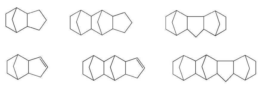

また、縮合多環炭化水素構造を含む高収縮性多官能(メタ)アクリレートは、(メタ)アクリロイル基以外の重合性基を有してもよい。重合性基としては、ラジカル重合性化合物および/またはエーテル基を官能基に有するカチオン重合性化合物中の重合性基が例示される。
(メタ)アクリロイル基や重合性基を含む置換基の結合位置は、特に限定されないが、いずれの置換基も、1つの環のみを構成している炭素原子に結合しているのが好ましい。また、同一の環に複数の置換基が結合する場合には、いずれの置換基も、互いに異なる炭素原子に結合しているのが好ましい。
大西パラメータとは、重合性単位容積あたりの炭素密度を示し、具体的には、重合性化合物の化学式に基づき、以下の式で求められるパラメータである。
式:(C,H,Oの全原子数)/(C原子数-O原子数)
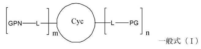
縮合多環炭化水素残基における炭素数は、8~50程度が一般的であり、8~25が好ましく、8~20がより好ましく、10~15がさらに好ましい。
一般式(I)の縮合多環炭化水素構造残基の例としては、前述の縮合多環炭化水素構造の例において、(m+n)個の水素が結合となっているものであればよい。
2価の連結基としては特に限定されないが、アルキレン基(例えば、エチレン基、1,2-プロピレン基、2,2-プロピレン基(2,2-プロピリデン基、1,1-ジメチルメチレン基とも呼ばれる)、1,3-プロピレン基、2,2-ジメチル-1,3-プロピレン基、2-ブチル-2-エチル-1,3-プロピレン基、1,6-ヘキシレン基、1,9-ノニレン基、1,12-ドデシレン基、1,16-ヘキサデシレン基等)、アリーレン基(例えば、フェニレン基、ナフチレン基)、エーテル基、イミノ基、カルボニル基、スルホニル基、およびこれらの2価の基が複数個直列に結合した2価残基(例えば、オキシエチレン基、オキシプロピレン基、2,2-プロピレンフェニレン基等)を挙げることができる。好ましい2価の連結基の例としては、アルキレン基、アルキレン基とエーテル基とが結合した基(オキシアルキレン基)があげられる。このとき、アルキレン基またはエーテル基のいずれがCycと結合していてもよい。より好ましい2価の連結基の例としては、メチレン基、エチレン基、1,3-プロピレン基、およびオキシエチレン基が挙げられる。
(メタ)アクリロイル基を含む置換基以外の重合性基としては、ラジカル重合性化合物および/またはエーテル基を官能基に有するカチオン重合性化合物中の重合性基が挙げられる。具体的には、ビニル基、エポキシ基、オキセタニル基、ビニルエーテル基等が挙げられる。
非重合性基としては、アルキル基(例えば、メチル基、エチル基、イソプロピル基、tert-ブチル基、n-オクチル基、n-デシル基、n-ヘキサデシル基、シクロプロピル基、シクロペンチル基、シクロヘキシル基等)、アルケニル基(例えば、ビニル基、アリル基、2-ブテニル基、3-ペンテニル基等)、アリール基(例えば、フェニル基、p-メチルフェニル基、ナフチル基、アンスリル基、フェナンスリル基、ピレニル基等)、ハロゲン原子(例えば、フッ素、塩素、臭素、ヨウ素)、ヒドロキシ基、アシル基(例えば、アセチル基、ベンゾイル基、ホルミル基、ピバロイル基等)、アシルオキシ基(例えば、アセトキシ基、アクリロイルオキシ基、メタクリロイルオキシ基等)、アルコキシカルボニル基(例えば、メトキシカルボニル基、エトキシカルボニル基等)、アリールオキシカルボニル基(例えば、フェニルオキシカルボニル基等)、スルホニル基(例えば、メタンスルホニル基、ベンゼンスルホニル基等)、スルフィニル基(メタンスルフィニル基、ベンゼンスルフィニル基等)、ヘテロ環基(好ましくは炭素数1~12であり、ヘテロ原子として窒素原子、酸素原子、硫黄原子等を含み、脂肪族ヘテロ環基であってもヘテロアリール基であってもよく、例えば、イミダゾリル基、ピリジル基、キノリル基、フリル基、チエニル基、ピペリジル基、モルホリノ基、ベンゾオキサゾリル基、ベンゾイミダゾリル基、ベンゾチアゾリル基、カルバゾリル基、アゼピニル基等)等が挙げられる。
nは、2が好ましい。mは、0または1が好ましい。
一例として、新中村化学社製のA-DCP、共栄社化学社製のライトアクリレートDCP-A)等が例示される。
一例として、変形抑制層20は、このような高収縮性多官能(メタ)アクリレートに加え、前述のTMPTA等の(メタ)アクリレートおよび/または前述のウレタンとアクリルとのグラフト共重合体を、併用して、形成してもよい。
これにより、高温での支持体12の変形を好適に抑制できる、変形抑制層20が紫外線硬化性に優れ生産性が良好になる、表面硬度が高い変形抑制層20を得られる等の点で好ましい。
従って、後述する変形抑制層20の形成においては、変形抑制層20における高収縮性多官能(メタ)アクリレートの量が、この範囲を満たすように、変形抑制層20を形成する塗布組成物における各成分の固形分濃度を調節するのが好ましい。
変形抑制層20の鉛筆硬度が3B以上であることにより、RtoR等を利用した製造時に変形抑制層20にスリ傷等の損傷が生じることを防止できる等の点で好ましい。
また、変形抑制層20の鉛筆硬度が3H以下であることにより、RtoR等を利用した製造時に有機層16や無機層18の損傷を防止できる等の点で好ましい。
なお、変形抑制層20の鉛筆硬度は、JIS K 5600-5-4に準拠して測定すればよい。
滑り剤となる粒子は、各種のものが利用可能である。一例として、ポリメチル(メタ)アクリレートまたはポリブチル(メタ)アクリレートを含む、好ましくはポリメチル(メタ)アクリレートまたはポリブチル(メタ)アクリレートからなる、粒径が0.01~10μmの粒子が例示される。
このような滑り剤となる粒子を含有することにより、ガスバリアフィルム10をRtoRによって製造する際に、支持体12の搬送を安定させて、高品質なガスバリアフィルムを安定して製造することが可能になる、巻取り時のシワの発生を抑制できる等の点で好ましい。
また、変形抑制層20における粒子の含有量は、使用する滑り剤粒子に応じて、適宜、設定すればよいが、変形抑制層20の樹脂成分に対して0.01~3質量%が好ましい。
本発明者の検討によれば、変形抑制層20の厚さは、支持体12の厚さの1~20%であるのが好ましく、2~10%であるのがより好ましい。
変形抑制層20の厚さを支持体12の厚さの1%以上とすることにより、支持体12の熱膨張を好適に抑制してガスバリア性および光学特性に優れるガスバリアフィルム10が得られる等の点で好ましい。
また、変形抑制層20の厚さを支持体12の厚さの20%以下とすることにより、ガスバリアフィルム10が不要に厚くなることを防止できる、変形抑制層20に起因するガスバリアフィルム10のカールを抑制できる、脆性の悪化を防止できる等の点で好ましい。
すなわち、前述の高収縮性多官能(メタ)アクリレート(体積収縮率が3~20%である、2官能以上の(メタ)アクリレート)を有機溶剤等に溶解あるいは分散してなる塗布組成物(重合性組成物)を調製する。次いで、支持体12の逆側面すなわちガスバリア層の非形成面に、調製した塗布組成物を塗布して、加熱等によって乾燥し、さらに、紫外線を照射して高収縮性多官能(メタ)アクリレートを硬化することで、変形抑制層20を形成する。
なお、高収縮性多官能(メタ)アクリレートを含む塗布組成物には、必要に応じて、光重合開始剤、界面活性剤、分散剤等を添加してもよい。また、高収縮性多官能(メタ)アクリレートを含む塗布組成物には、必要に応じて、前述のグラフト共重合や滑り剤粒子等を添加してもよい。
なお、図2に示すガスバリアフィルム26のように、下地となる有機層16と無機層18との組み合わせを、2組以上、有するガスバリアフィルムの製造は、有機層と無機層との組み合わせの数に応じて、有機層16と無機層18との交互の形成を、繰り返して行えばよい。
[実施例1]
<支持体12>
支持体12として、幅1000mm、厚さ100μm、長さ100mのCOPフィルム(JSR社製、アートンフィルム)を用いた。
この支持体12は、熱膨張係数が60×10-6/℃、水蒸気透過率(WVTR)が90g/(m2・day)のものである。
高収縮性多官能(メタ)アクリレートであるトリシクロデカンジメタノールジアクリレート(新中村化学社製、A-DCP)と、重合開始剤(ランベルティ社製、ESACURE KTO46)とを用意し、質量比率として93:7となるように秤量した。これらを固形分濃度が20質量%となるようにメチルエチルケトン(MEK)に溶解して、変形抑制層20を形成するための塗布組成物を調製した。
トリシクロデカンジメタノールジアクリレートは、縮合多環炭化水素構造を含む2官能アクリレートである。また、硬化後のトリシクロデカンジメタノールジアクリレートの体積収縮率は、5.9%である。
成膜装置において、支持体12を長手方向に搬送しつつ、支持体12にダイコータによって塗布組成物を塗布し、50℃の乾燥ゾーンを3分間通過させた。その後、硬化ゾーンで紫外線を照射(積算照射量約600mJ/cm2)して、支持体12の一面に変形抑制層20を形成した。
塗布組成物の塗布量は、10mL(リットル)/m2とした。形成した変形抑制層20の厚さは2μmであった。
また、JIS K 5600-5-4に準拠して,変形抑制層20の鉛筆硬度を測定したところ、HBであった。
変形抑制層20を形成した支持体12のロールを、RtoRを用いて、CCP-CVD(容量結合型プラズマCVD)によって成膜を行う、一般的なCVD成膜装置の所定位置に装填し、支持体12を所定の搬送経路に挿通した。
このCVD成膜装置において、変形抑制層20を形成した支持体12を長手方向に搬送しつつ、支持体12の変形抑制層20を形成した面とは逆側の面に、無機層18として窒化ケイ素膜を形成した。無機層18を形成した支持体12を巻き取り、ガスバリアフィルムを得た。
すなわち、このガスバリアフィルムは、図3に示すガスバリアフィルム30と同様の構成を有する。
原料ガスは、シランガス(流量160sccm)、アンモニアガス(流量370sccm)、水素ガス(流量590sccm)および窒素ガス(流量240sccm)を用いた。電源は、周波数13.56MHzの高周波電源を用い、プラズマ励起電力は800Wとした。成膜圧力は40Paとした。無機層18の膜厚は、35nmであった。
支持体12を、幅1000mm、厚さ100μm、長さ100mのCOCフィルム(グンゼ社製、F1フィルム)に変更した以外は、実施例1と同様にガスバリアフィルムを作製した。
この支持体12は、熱膨張係数が70×10-6/℃、水蒸気透過率が2g/(m2・day)のものである。
支持体12を、アートンフィルムから、同じCOPフィルムである、幅1000mm、厚さ100μm、長さ100mのゼオノアフィルムF16(日本ゼオン社製)に変更した以外は、実施例1と同様にガスバリアフィルムを作製した。
この支持体12は、熱膨張係数が60×10-6/℃、水蒸気透過率が4g/(m2・day)のものである。
支持体12を、幅1000mm、厚さ100μm、長さ100mのTACフィルム(富士フイルム社製、富士タック)に変更した以外は、実施例1と同様にガスバリアフィルムを作製した。
この支持体12は、熱膨張係数が70×10-6/℃、水蒸気透過率が300g/(m2・day)のものである。
支持体12を、幅1000mm、厚さ100μm、長さ100mの特殊PCフィルム(帝人社製、W148)に変更した以外は、実施例1と同様にガスバリアフィルムを作製した。
この支持体12は、熱膨張係数が90×10-6/℃、水蒸気透過率が150g/(m2・day)のものである。
無機層18の形成に先立ち、支持体12の変形抑制層20の非形成面に、無機層18の下地となる有機層16を形成し、その後、無機層18を形成した以外は、実施例1と同様にガスバリアフィルムを作製した。
下地の有機層16の形成は、以下のように行った。
トリシクロデカンジメタノールジアクリレート(新中村化学社製、A-DCP)と、重合開始剤(ランベルティ社製、ESACURE KTO46)とを用意し、質量比率として93:7となるように秤量した。これらを固形分濃度が20質量%となるようにMEKに溶解して、有機層16を形成するための塗布組成物を調製した。
ダイコータによる塗布部、加熱による乾燥ゾーン、紫外線照射による硬化ゾーンを有する、一般的なRtoRによる成膜装置の塗布部の所定位置に、調製した塗布組成物を充填した。また、支持体12を巻回したロールを、成膜装置の所定位置に装填して、所定の搬送経路に挿通した。
成膜装置において、支持体12を長手方向に搬送しつつ、支持体12にダイコータによって塗布組成物を塗布し、50℃の乾燥ゾーンを3分間通過させた。その後、硬化ゾーンで紫外線を照射(積算照射量約600mJ/cm2)して、支持体12の変形抑制層20の非形成面に有機層16を形成した。有機層16を形成した支持体12にPE製の保護フィルムを貼着した後、巻き取り、ガスバリアフィルムを得た。
塗布組成物の塗布量は、10mL/m2とした。形成した下地の有機層16の厚さは2μmであった。下地の有機層16を形成するトリシクロデカンジメタノールジアクリレートの体積収縮率は5.9%であり、変形抑制層20を形成する(メタ)アクリレート(A-DCP)の体積収縮率と同じである。
トリシクロデカンジメタノールジアクリレート(新中村化学社製、A-DCP)と、DPHA(新中村化学社製)と、重合開始剤(ランベルティ社製、ESACURE KTO46)
とを用意し、質量比率として50:43:7となるように秤量した。これらを固形分濃度が20質量%となるようにMEKに溶解して、有機層16を形成するための塗布組成物を調製した。
この塗布組成物を用いて下地となる有機層16を形成した以外は、実施例6-1と同様にガスバリアフィルムを作製した。下地の有機層16を形成するトリシクロデカンジメタノールジアクリレートとDPHAとの混合物の体積収縮率は9%であり、変形抑制層20を形成する(メタ)アクリレート(A-DCP)との体積収縮率の差は3.1%である。
DPHA(新中村化学社製)と、重合開始剤(ランベルティ社製、ESACURE KTO46)とを用意し、質量比率として93:7となるように秤量した。これらを固形分濃度が20質量%となるようにMEKに溶解して、有機層16を形成するための塗布組成物を調製した。
この塗布組成物を用いて下地となる有機層16を形成した以外は、実施例6-1と同様にガスバリアフィルムを作製した。下地の有機層16を形成するDPHAの体積収縮率は12%であり、変形抑制層20を形成する(メタ)アクリレート(A-DCP)との体積収縮率の差は6.1%である。
無機層18を形成した後に、無機層18の上に保護層となる最表層の有機層16を形成した以外は、実施例1と同様にガスバリアフィルムを作製した。
最表層の有機層16の形成は、以下のように行った。
ウレタンアクリレートのグラフト共重合体(大成ファインケミカル社製、アクリット8BR-930)と、光重合開始剤(BASF社製、イルガキュア184)と、シランカップリング剤(信越シリコーン社製、KBM5103)と、軟化剤(東洋紡社製、バイロンU1400)とを、質量比率として78:10:10:2となるように秤量した。これらを固形分濃度が15質量%となるようにMEKに溶解して、最表層の有機層16を形成するための塗布組成物を調製した。
成膜装置において、ガスバリアフィルム30を長手方向に搬送しつつ、保護フィルムを剥離し、ダイコータによって無機層18に塗布組成物を塗布し、100℃の乾燥ゾーンを3分間通過させた。その後、硬化ゾーンにおいて紫外線を照射(積算照射量約600mJ/cm2)して塗布組成物を硬化させて最表層の有機層16を形成して、ロール状に巻き取り、ガスバリアフィルムを作製した。 形成した最表層の有機層16の厚さは1μmであった。
無機層18の形成に先立ち、実施例6と同様に下地の有機層16を形成し、無機層18を形成した後に、実施例7と同様に最表層の有機層16を形成した以外は、実施例1と同様にガスバリアフィルムを作製した。
すなわち、このガスバリアフィルムは、図1に示すガスバリアフィルム10と同様の構成を有する。
無機層18を形成した後で、かつ、無機層18が最初のパスロールに接触する前に、無機層18にPE製の保護フィルムを貼着した以外は、実施例1と同様にガスバリアフィルムを作製した。
変形抑制層20の形成において、ダイコータによる塗布組成物の塗布量を変更した以外は、実施例1と同様にガスバリアフィルムを作製した。
形成した変形抑制層20の厚さは、0.8μmであった。
変形抑制層20の形成において、ダイコータによる塗布組成物の塗布量を変更した以外は、実施例1と同様にガスバリアフィルムを作製した。
形成した変形抑制層20の厚さは、10μmであった。
変形抑制層20の形成において、ダイコータによる塗布組成物の塗布量を変更した以外は、実施例1と同様にガスバリアフィルムを作製した。
形成した変形抑制層20の厚さは、16μmであった。
変形抑制層20を形成する塗布組成物の調製において、トリシクロデカンジメタノールジアクリレート(新中村化学社製、A-DCP)と、DPHA(新中村化学社製)と、重合開始剤(ランベルティ社製、ESACURE KTO46)とを用意し、質量比率として48:48:4となるように秤量した。これらを固形分濃度が20質量%となるようにMEKに溶解して、変形抑制層20を形成するための塗布組成物を調製した。トリシクロデカンジメタノールジアクリレートとDPHAとの混合物の体積収縮率は12%である。
この塗布組成物を用いて変形抑制層20を形成した以外は、実施例1と同様にガスバリアフィルムを作製した。
変形抑制層20を形成する形成した変形抑制層20の厚さは2μmであった。実施例1と同様に変形抑制層20の鉛筆硬度を測定したところ、3Hであった。
変形抑制層20を形成する塗布組成物の調製において、トリシクロデカンジメタノールジアクリレート(新中村化学社製、A-DCP)と、ウレタンアクリレートのグラフト共重合体(大成ファインケミカル社製、アクリット8BR-930)と、重合開始剤(ランベルティ社製、ESACURE KTO46)とを用意し、質量比率として67:30:3となるように秤量した。これらを固形分濃度が20質量%となるようにMEKに溶解して、変形抑制層20を形成するための塗布組成物を調製した。変形抑制層20を形成するトリシクロデカンジメタノールジアクリレートとウレタンアクリレートのグラフト共重合体との混合物の体積収縮率は3%である。
この塗布組成物を用いて変形抑制層20を形成した以外は、実施例1と同様にガスバリアフィルムを作製した。
形成した変形抑制層20の厚さは2μmであった。実施例1と同様に変形抑制層20の鉛筆硬度を測定したところ、Bであった。
変形抑制層20を形成する塗布組成物の調製において、トリシクロデカンジメタノールジアクリレートおよび重合開始剤の100質量部に対して、滑り剤粒子として粒径1.5μmのポリメチルメタクリレート(PMMA)粒子(綜研科学社製、MX150)を1.5質量部添加して、変形抑制層20を形成するための塗布組成物を調製した。
この塗布組成物を用いて変形抑制層20を形成した以外は、実施例1と同様にガスバリアフィルムを作製した。
形成した変形抑制層20の厚さは2μmであった。実施例1と同様に変形抑制層20の鉛筆硬度を測定したところ、HBであった。
変形抑制層20を形成する塗布組成物の調製において、トリシクロデカンジメタノールジアクリレートおよび重合開始剤の100質量部に対して、滑り剤粒子として粒径5μmのPMMA粒子(綜研科学社製、MX500)を1.5質量部添加して、変形抑制層20を形成するための塗布組成物を調製した。
この塗布組成物を用いて変形抑制層20を形成した以外は、実施例1と同様にガスバリアフィルムを作製した。
形成した変形抑制層20の厚さは2μmであった。実施例1と同様に変形抑制層20の鉛筆硬度を測定したところ、HBであった。
変形抑制層20を形成しない以外は、実施例1と同様にガスバリアフィルムを作製した。
変形抑制層20を形成する塗布組成物の調製において、TMPTA(ダイセルサイテック社製)および光重合開始剤(ランベルティ社製、ESACURE KTO46)を用意し、質量比率として97:3となるように秤量した。これらを固形分濃度が20質量%となるようにMEKに溶解して、変形抑制層20を形成するための塗布組成物を調製した。
硬化後のTMPTAの体積収縮率は25%である。
この塗布組成物を用いて変形抑制層20を形成した以外は、実施例1と同様にガスバリアフィルムを作製した。
形成した変形抑制層20の厚さは2μmであった。実施例1と同様に変形抑制層20の鉛筆硬度を測定したところ、3Hであった。
作製した各ガスバリアフィルムについて、ガスバリア性、耐久性、カールおよび密着性の評価を行った。なお、無機層18を形成した後に保護フィルムを貼着した実施例9は、以下の評価は、保護フィルムを剥離して行った。
<ガスバリア性の評価(WVTR)>
作製した各ガスバリアフィルムの水蒸気透過率[g/(m2・day)]を、カルシウム腐食法(特開2005-283561号公報に記載される方法)によって測定し、作製後のガスバリア性を評価した。なお、恒温恒湿処理の条件は、温度40℃、湿度90%RHとした。
評価は、以下のとおりである。
A: 水蒸気透過率が5×10⁻⁵[g/(m2・day)]未満
B: 水蒸気透過率が5×10⁻⁵ [g/(m2・day)]以上、1×10-4[g/(m2・day)]未満
C: 水蒸気透過率が1×10⁻⁴[g/(m2・day)]以上、5×10-4[g/(m2・day)]未満
D: 水蒸気透過率が5×10⁻⁴[g/(m2・day)]以上、1×10-3[g/(m2・day)]未満
E: 水蒸気透過率が1×10⁻³[g/(m2・day)]以上
温度85℃、湿度85%RHの環境下に、250時間、放置した後、先と同様にして、ガスバリアフィルムの水蒸気透過率を測定した。
評価は、上述のガスバリア性の評価と同様に行った。
作製した各ガスバリアフィルムを、トムソン刃によって一辺が10cmの正方形状に打ち抜いたサンプルを用いて、カールを測定した。サンプルを載置面に載置し、サンプルの四隅において、設置面からサンプルまでの距離を測定し、四隅の距離の平均値を算出した。なお、測定は、変形抑制層20面側を上にして行った。
JIS K5400に準拠したクロスカット剥離試験で評価した。
具体的には、各ガスバリアフィルムの変形抑制層20の形成面に、カッターナイフを用いて膜面に対して90°の切り込みを1mm間隔で入れ、1mm間隔の碁盤目を100個作成した。この上に2cm幅のマイラーテープ(日東電工製、ポリエステルテープ、No.31B)で貼り付けたテープを剥がした。支持体の上に形成した変形抑制層20が残存したマスの数で評価した。
評価は、以下のとおりである。
A: 残存マス数が90マス以上のもの
B: 残存マス数が80~89マスのもの
C: 残存マス数が70~79マスのもの
D: 残存マス数が70マス以下のもの
結果を下記の表に示す。
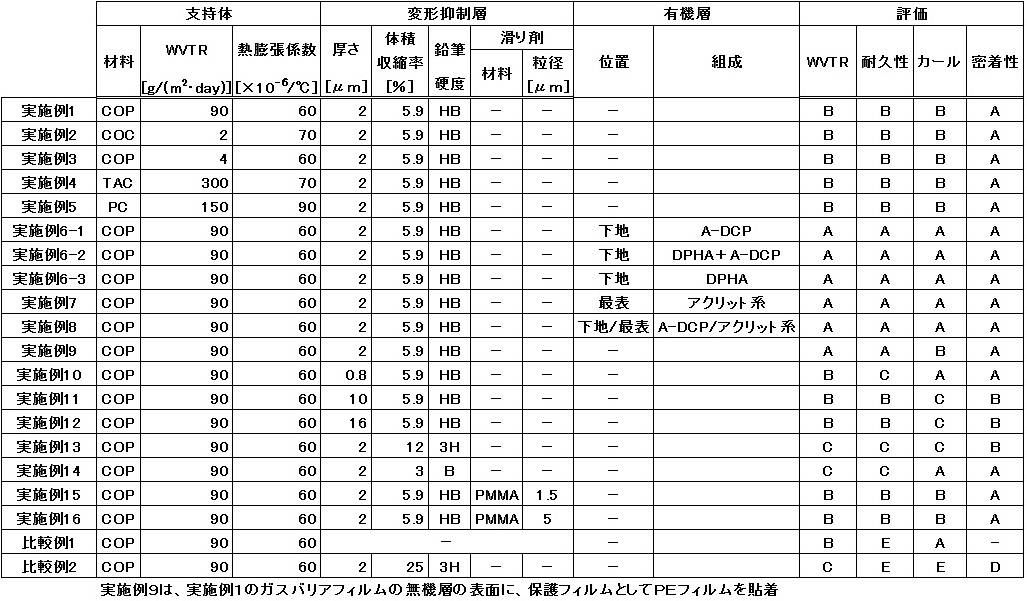
また、実施例4および実施例5に示されるように、本発明のガスバリアフィルムは、水蒸気透過率(WVTR)が高い支持体を用いた場合であっても、高温多湿の環境下に曝しても無機層の損傷を防止でき、優れたガスバリア性が維持された。
これに対して、変形抑制層を有さない比較例1は、作製後のガスバリア性は優れているが、高温高湿の環境下に曝すと、支持体の熱膨張に起因して無機層が損傷してしまい、ガスバリア性が著しく低下した。また、変形抑制層を形成する(メタ)アクリレートの体積収縮率が大きい比較例2は、作製後のガスバリア性は良好でも、高温高湿の環境下に曝すと、支持体の熱膨張に起因して無機層が損傷してガスバリア性が著しく低下し、さらに、カールが大きく生じ、変形抑制層の密着性も低下した。
以上の結果より、本発明の効果は明らかである。
12 支持体
16 有機層
18 無機層
20 変形抑制層
Claims (16)
- 支持体と、
前記支持体の一方の面に設けられる、無機層を含むガスバリア層と、
前記支持体の前記ガスバリア層が設けられた側とは逆側の面に設けられる、2官能以上の(メタ)アクリレートを含む変形抑制層と、を有し、
前記支持体の熱膨張係数が30×10-6/℃以上であり、
前記変形抑制層の(メタ)アクリレートは、体積収縮率が3~20%であることを特徴とするガスバリアフィルム。 - 前記支持体のリタデーション値が150nm以下である請求項1に記載のガスバリアフィルム。
- 前記変形抑制層の(メタ)アクリレートが、縮合多環炭化水素構造を含む請求項1または2に記載のガスバリアフィルム。
- 前記ガスバリア層が、前記支持体に当接する有機層を有する請求項1~3のいずれか1項に記載のガスバリアフィルム。
- 前記支持体に当接する有機層が、2官能以上の(メタ)アクリレートを含み、
前記支持体に当接する有機層の(メタ)アクリレートは、体積収縮率が3~20%である請求項4に記載のガスバリアフィルム。 - 前記変形抑制層の(メタ)アクリレートの体積収縮率と、前記支持体に当接する有機層の(メタ)アクリレートの体積収縮率との差が15%以内である請求項5に記載のガスバリアフィルム。
- 前記支持体に当接する有機層の(メタ)アクリレートが、縮合多環炭化水素構造を含む請求項5または6に記載のガスバリアフィルム。
- 前記ガスバリア層が、前記無機層と、前記無機層の下地となる有機層との組み合わせを1組以上有する請求項4~7のいずれか1項に記載のガスバリアフィルム。
- 前記ガスバリア層が複数の層を有し、前記複数の層のうちの前記支持体と最も離間する層が有機層である請求項1~8のいずれか1項に記載のガスバリアフィルム。
- 前記ガスバリア層の表面に、ポリエチレンもしくはポリプロピレンからなる保護フィルムが設けられる請求項1~9のいずれか1項に記載のガスバリアフィルム。
- 前記支持体の、温度40℃、湿度90%RHにおける水蒸気透過率が10g/(m2・day)以上である請求項1~10のいずれか1項に記載のガスバリアフィルム。
- 前記変形抑制層の厚さが、前記支持体の厚さの1~20%である請求項1~11のいずれか1項に記載のガスバリアフィルム。
- 前記変形抑制層の鉛筆硬度が3B~3Hである請求項1~12のいずれか1項に記載のガスバリアフィルム。
- 前記変形抑制層が滑り剤となる粒子を含有する請求項1~13のいずれか1項に記載のガスバリアフィルム。
- 前記粒子が、ポリメチル(メタ)アクリレートまたはポリブチル(メタ)アクリレートを含み、粒径が0.01~10μmである請求項14に記載のガスバリアフィルム。
- 前記無機層がケイ素化合物からなる請求項1~15のいずれか1項に記載のガスバリアフィルム。
Priority Applications (2)
| Application Number | Priority Date | Filing Date | Title |
|---|---|---|---|
| KR1020187026559A KR102134983B1 (ko) | 2016-03-17 | 2017-01-27 | 가스 배리어 필름 |
| US16/128,013 US10647097B2 (en) | 2016-03-17 | 2018-09-11 | Gas barrier film |
Applications Claiming Priority (2)
| Application Number | Priority Date | Filing Date | Title |
|---|---|---|---|
| JP2016053231A JP6469606B2 (ja) | 2016-03-17 | 2016-03-17 | ガスバリアフィルム |
| JP2016-053231 | 2016-03-17 |
Related Child Applications (1)
| Application Number | Title | Priority Date | Filing Date |
|---|---|---|---|
| US16/128,013 Continuation US10647097B2 (en) | 2016-03-17 | 2018-09-11 | Gas barrier film |
Publications (1)
| Publication Number | Publication Date |
|---|---|
| WO2017159071A1 true WO2017159071A1 (ja) | 2017-09-21 |
Family
ID=59852225
Family Applications (1)
| Application Number | Title | Priority Date | Filing Date |
|---|---|---|---|
| PCT/JP2017/002976 Ceased WO2017159071A1 (ja) | 2016-03-17 | 2017-01-27 | ガスバリアフィルム |
Country Status (4)
| Country | Link |
|---|---|
| US (1) | US10647097B2 (ja) |
| JP (1) | JP6469606B2 (ja) |
| KR (1) | KR102134983B1 (ja) |
| WO (1) | WO2017159071A1 (ja) |
Families Citing this family (1)
| Publication number | Priority date | Publication date | Assignee | Title |
|---|---|---|---|---|
| JP2018105129A (ja) * | 2016-12-22 | 2018-07-05 | 株式会社ニッキ | 燃料供給装置 |
Citations (4)
| Publication number | Priority date | Publication date | Assignee | Title |
|---|---|---|---|---|
| JP2009083465A (ja) * | 2007-09-14 | 2009-04-23 | Fujifilm Corp | ガスバリアフィルムおよびこれを用いた表示素子 |
| JP2010184409A (ja) * | 2009-02-12 | 2010-08-26 | Toppan Printing Co Ltd | ガスバリア性積層フィルムの製造方法 |
| JP2015157411A (ja) * | 2014-02-24 | 2015-09-03 | 大日本印刷株式会社 | ガスバリアフィルム及びその製造方法 |
| JP2015189047A (ja) * | 2014-03-27 | 2015-11-02 | 富士フイルム株式会社 | 機能性フィルムおよび機能性フィルムの製造方法 |
Family Cites Families (9)
| Publication number | Priority date | Publication date | Assignee | Title |
|---|---|---|---|---|
| JP2008046495A (ja) * | 2006-08-18 | 2008-02-28 | Nippon Zeon Co Ltd | 光学積層フィルム、偏光光源装置、及び液晶表示装置 |
| US8067085B2 (en) * | 2007-09-14 | 2011-11-29 | Fujifilm Corporation | Gas barrier film, and display device comprising the same |
| JP5463680B2 (ja) * | 2009-02-06 | 2014-04-09 | 凸版印刷株式会社 | 透明導電性フィルム |
| JP5472685B2 (ja) * | 2009-05-27 | 2014-04-16 | Dic株式会社 | 飛散防止粘着シート |
| JP5795825B2 (ja) | 2012-08-17 | 2015-10-14 | 富士フイルム株式会社 | 機能性フィルムおよび有機elデバイス |
| JP6508869B2 (ja) * | 2013-02-14 | 2019-05-08 | 日東電工株式会社 | 粘着剤組成物、粘着剤層、粘着シート、光学部材、及びタッチパネル |
| JP6040059B2 (ja) * | 2013-03-07 | 2016-12-07 | 富士フイルム株式会社 | バリア性積層体およびガスバリアフィルム |
| JP2015069197A (ja) * | 2013-10-01 | 2015-04-13 | Dic株式会社 | ハードコートフィルム及び画像表示装置 |
| JPWO2015137389A1 (ja) * | 2014-03-11 | 2017-04-06 | コニカミノルタ株式会社 | ガスバリアーフィルムの製造方法 |
-
2016
- 2016-03-17 JP JP2016053231A patent/JP6469606B2/ja not_active Expired - Fee Related
-
2017
- 2017-01-27 KR KR1020187026559A patent/KR102134983B1/ko not_active Expired - Fee Related
- 2017-01-27 WO PCT/JP2017/002976 patent/WO2017159071A1/ja not_active Ceased
-
2018
- 2018-09-11 US US16/128,013 patent/US10647097B2/en not_active Expired - Fee Related
Patent Citations (4)
| Publication number | Priority date | Publication date | Assignee | Title |
|---|---|---|---|---|
| JP2009083465A (ja) * | 2007-09-14 | 2009-04-23 | Fujifilm Corp | ガスバリアフィルムおよびこれを用いた表示素子 |
| JP2010184409A (ja) * | 2009-02-12 | 2010-08-26 | Toppan Printing Co Ltd | ガスバリア性積層フィルムの製造方法 |
| JP2015157411A (ja) * | 2014-02-24 | 2015-09-03 | 大日本印刷株式会社 | ガスバリアフィルム及びその製造方法 |
| JP2015189047A (ja) * | 2014-03-27 | 2015-11-02 | 富士フイルム株式会社 | 機能性フィルムおよび機能性フィルムの製造方法 |
Also Published As
| Publication number | Publication date |
|---|---|
| JP6469606B2 (ja) | 2019-02-13 |
| US10647097B2 (en) | 2020-05-12 |
| US20190001646A1 (en) | 2019-01-03 |
| KR102134983B1 (ko) | 2020-07-16 |
| KR20180114144A (ko) | 2018-10-17 |
| JP2017165004A (ja) | 2017-09-21 |
Similar Documents
| Publication | Publication Date | Title |
|---|---|---|
| CN103764386B (zh) | 屏障层合物以及具有其的器件与密封袋、气体屏障膜及其制造方法 | |
| JP5934544B2 (ja) | ガスバリアフィルム | |
| JP6277142B2 (ja) | 機能性複合フィルムおよび量子ドットフィルム | |
| JP5485624B2 (ja) | バリア性積層体およびこれを用いたガスバリアフィルム | |
| JP5090197B2 (ja) | 積層体の製造方法、バリア性フィルム基板、デバイスおよび光学部材 | |
| JP2013043383A (ja) | バリア性積層体、ガスバリアフィルムおよびこれらを用いたデバイス | |
| JP2010030295A (ja) | バリア性積層体、ガスバリアフィルム、デバイスおよび光学部材 | |
| JP5635955B2 (ja) | バリア性積層体、ガスバリアフィルムおよびこれらを用いたデバイス | |
| JP6603811B2 (ja) | ガスバリアフィルムおよびガスバリアフィルムの製造方法 | |
| TW201815584A (zh) | 氣體阻擋膜及太陽電池以及氣體阻擋膜的製造方法 | |
| JP5373479B2 (ja) | バリア性積層体、ガスバリアフィルムおよびこれらを用いたデバイス | |
| KR20160035045A (ko) | 배리어성 적층체, 가스 배리어 필름, 및 디바이스 | |
| US11203180B2 (en) | Gas barrier film and method for producing gas barrier film | |
| JP2016204461A (ja) | 機能性フィルムおよび機能性フィルムの製造方法 | |
| JP6469606B2 (ja) | ガスバリアフィルム | |
| JP2009172991A (ja) | バリア性積層体、バリア性フィルム基板、デバイスおよび光学部材 | |
| JP6683836B2 (ja) | ガスバリアフィルムおよびガスバリアフィルムの製造方法 | |
| JP6469605B2 (ja) | ガスバリアフィルム | |
| WO2018207508A1 (ja) | ガスバリアフィルムおよびガスバリアフィルムの製造方法 | |
| JP2013202972A (ja) | バリア性積層体、ガスバリアフィルムおよびこれらを用いたデバイス |
Legal Events
| Date | Code | Title | Description |
|---|---|---|---|
| ENP | Entry into the national phase |
Ref document number: 20187026559 Country of ref document: KR Kind code of ref document: A |
|
| WWE | Wipo information: entry into national phase |
Ref document number: 1020187026559 Country of ref document: KR |
|
| NENP | Non-entry into the national phase |
Ref country code: DE |
|
| 121 | Ep: the epo has been informed by wipo that ep was designated in this application |
Ref document number: 17766079 Country of ref document: EP Kind code of ref document: A1 |
|
| 122 | Ep: pct application non-entry in european phase |
Ref document number: 17766079 Country of ref document: EP Kind code of ref document: A1 |