WO2017158852A1 - プローバ - Google Patents
プローバ Download PDFInfo
- Publication number
- WO2017158852A1 WO2017158852A1 PCT/JP2016/060790 JP2016060790W WO2017158852A1 WO 2017158852 A1 WO2017158852 A1 WO 2017158852A1 JP 2016060790 W JP2016060790 W JP 2016060790W WO 2017158852 A1 WO2017158852 A1 WO 2017158852A1
- Authority
- WO
- WIPO (PCT)
- Prior art keywords
- unit
- transport
- probe card
- measurement unit
- transported object
- Prior art date
- Legal status (The legal status is an assumption and is not a legal conclusion. Google has not performed a legal analysis and makes no representation as to the accuracy of the status listed.)
- Ceased
Links
Images









Classifications
-
- H—ELECTRICITY
- H10—SEMICONDUCTOR DEVICES; ELECTRIC SOLID-STATE DEVICES NOT OTHERWISE PROVIDED FOR
- H10P—GENERIC PROCESSES OR APPARATUS FOR THE MANUFACTURE OR TREATMENT OF DEVICES COVERED BY CLASS H10
- H10P72/00—Handling or holding of wafers, substrates or devices during manufacture or treatment thereof
- H10P72/50—Handling or holding of wafers, substrates or devices during manufacture or treatment thereof for positioning, orientation or alignment
-
- G—PHYSICS
- G01—MEASURING; TESTING
- G01R—MEASURING ELECTRIC VARIABLES; MEASURING MAGNETIC VARIABLES
- G01R31/00—Arrangements for testing electric properties; Arrangements for locating electric faults; Arrangements for electrical testing characterised by what is being tested not provided for elsewhere
- G01R31/28—Testing of electronic circuits, e.g. by signal tracer
- G01R31/2851—Testing of integrated circuits [IC]
- G01R31/2855—Environmental, reliability or burn-in testing
- G01R31/286—External aspects, e.g. related to chambers, contacting devices or handlers
- G01R31/2868—Complete testing stations; systems; procedures; software aspects
-
- G—PHYSICS
- G01—MEASURING; TESTING
- G01R—MEASURING ELECTRIC VARIABLES; MEASURING MAGNETIC VARIABLES
- G01R1/00—Details of instruments or arrangements of the types included in groups G01R5/00 - G01R13/00 and G01R31/00
- G01R1/02—General constructional details
- G01R1/06—Measuring leads; Measuring probes
- G01R1/067—Measuring probes
- G01R1/073—Multiple probes
- G01R1/07307—Multiple probes with individual probe elements, e.g. needles, cantilever beams or bump contacts, fixed in relation to each other, e.g. bed of nails fixture or probe card
-
- G—PHYSICS
- G01—MEASURING; TESTING
- G01R—MEASURING ELECTRIC VARIABLES; MEASURING MAGNETIC VARIABLES
- G01R31/00—Arrangements for testing electric properties; Arrangements for locating electric faults; Arrangements for electrical testing characterised by what is being tested not provided for elsewhere
- G01R31/28—Testing of electronic circuits, e.g. by signal tracer
- G01R31/2851—Testing of integrated circuits [IC]
- G01R31/2893—Handling, conveying or loading, e.g. belts, boats, vacuum fingers
-
- H—ELECTRICITY
- H10—SEMICONDUCTOR DEVICES; ELECTRIC SOLID-STATE DEVICES NOT OTHERWISE PROVIDED FOR
- H10P—GENERIC PROCESSES OR APPARATUS FOR THE MANUFACTURE OR TREATMENT OF DEVICES COVERED BY CLASS H10
- H10P72/00—Handling or holding of wafers, substrates or devices during manufacture or treatment thereof
- H10P72/30—Handling or holding of wafers, substrates or devices during manufacture or treatment thereof for conveying, e.g. between different workstations
- H10P72/34—Handling or holding of wafers, substrates or devices during manufacture or treatment thereof for conveying, e.g. between different workstations the wafers being stored in a carrier, involving loading and unloading
-
- H—ELECTRICITY
- H10—SEMICONDUCTOR DEVICES; ELECTRIC SOLID-STATE DEVICES NOT OTHERWISE PROVIDED FOR
- H10P—GENERIC PROCESSES OR APPARATUS FOR THE MANUFACTURE OR TREATMENT OF DEVICES COVERED BY CLASS H10
- H10P74/00—Testing or measuring during manufacture or treatment of wafers, substrates or devices
- H10P74/20—Testing or measuring during manufacture or treatment of wafers, substrates or devices characterised by the properties tested or measured, e.g. structural or electrical properties
- H10P74/203—Structural properties, e.g. testing or measuring thicknesses, line widths, warpage, bond strengths or physical defects
-
- H—ELECTRICITY
- H10—SEMICONDUCTOR DEVICES; ELECTRIC SOLID-STATE DEVICES NOT OTHERWISE PROVIDED FOR
- H10P—GENERIC PROCESSES OR APPARATUS FOR THE MANUFACTURE OR TREATMENT OF DEVICES COVERED BY CLASS H10
- H10P74/00—Testing or measuring during manufacture or treatment of wafers, substrates or devices
- H10P74/23—Testing or measuring during manufacture or treatment of wafers, substrates or devices characterised by multiple measurements, corrections, marking or sorting processes
-
- H—ELECTRICITY
- H10—SEMICONDUCTOR DEVICES; ELECTRIC SOLID-STATE DEVICES NOT OTHERWISE PROVIDED FOR
- H10P—GENERIC PROCESSES OR APPARATUS FOR THE MANUFACTURE OR TREATMENT OF DEVICES COVERED BY CLASS H10
- H10P74/00—Testing or measuring during manufacture or treatment of wafers, substrates or devices
- H10P74/27—Structural arrangements therefor
- H10P74/277—Circuits for electrically characterising or monitoring manufacturing processes, e.g. circuits in tested chips or circuits in testing wafers
-
- G—PHYSICS
- G01—MEASURING; TESTING
- G01R—MEASURING ELECTRIC VARIABLES; MEASURING MAGNETIC VARIABLES
- G01R31/00—Arrangements for testing electric properties; Arrangements for locating electric faults; Arrangements for electrical testing characterised by what is being tested not provided for elsewhere
- G01R31/28—Testing of electronic circuits, e.g. by signal tracer
- G01R31/2851—Testing of integrated circuits [IC]
- G01R31/2886—Features relating to contacting the IC under test, e.g. probe heads; chucks
- G01R31/2887—Features relating to contacting the IC under test, e.g. probe heads; chucks involving moving the probe head or the IC under test; docking stations
Definitions
- the present invention relates to a prober for inspecting electrical characteristics of a plurality of semiconductor elements (chips) formed on a semiconductor wafer, and more particularly to a prober having a drawing mechanism for pulling out a maintenance target device to the maintenance area side.
- the present invention has been made in view of such circumstances, up to a position where a plurality of measuring units provided with a maintenance target device and a pull-out mechanism for pulling out the maintenance target device, and a position where the measurement unit at the transport destination of the transported object can be accessed.
- a prober equipped with a transport unit that moves and transports a transported object into a measurement unit of a transport destination it suppresses Abbe error that must be taken into account when positioning a maintenance target device that requires high accuracy ( Or to eliminate).
- it is possible to load the transported object into the measuring unit from both sides, and to perform the inspection efficiently by properly using the loading direction of the transported object to the measuring unit depending on the use state of the measuring unit or the transported object.
- the purpose is to provide a prober capable of
- a prober is a plurality of measurement units arranged between a transfer area and a maintenance area, and is used for inspecting a semiconductor element formed on a wafer. It has a plurality of measuring units equipped with a maintenance device and a pull-out mechanism that pulls out the device to be maintained to the maintenance area side, and a housing for storing the transported object, and accesses the measuring unit at the transport destination of the transported object in the transport area.
- a pull-out direction of the maintenance target apparatus comprising: a transport unit that moves to a possible position and transports and loads a transported object into a measurement unit at a transport destination; and a loading unit that loads a transported object from the maintenance area side to the measurement unit.
- the conveyance direction of the conveyed product is linear, and the measurement unit can be loaded with the conveyed product from the conveyance area side and the maintenance area side.
- the measurement unit can be loaded with the transported object from the transport area side and the maintenance area side, the transported object is loaded into the measurement unit according to the use state of the measurement unit or the transported object.
- the direction can be properly used, and an efficient inspection can be performed.
- the transport unit loads the transported object into the measuring unit when the transported object is for inspection of a semiconductor element, and the loading unit uses the transported object to calibrate the position of the measuring unit. If it is possible, the transported object is loaded into the measuring section.
- the transport unit loads the transport object into the measurement unit (loading from the transport area side) when the transport object is for inspection of a semiconductor element, and the loading unit is configured so that the transport object is positioned at the measurement unit.
- the transported material is loaded into the measuring section (loading from the maintenance area side), so the loading direction to the measuring section can be used differently for inspection and calibration applications. Inspection can be performed.
- the transport unit loads the transported object to the measuring unit when the transported object requires control of the environment, and the loading unit does not control the environment of the transported object. Load the conveyed product into the measuring unit.
- the transport unit loads the transported object into the measurement unit (loading from the transport area side) when the transported object needs to control the environment, and the loading unit needs to control the environment of the transported object. If not, since the transported object is loaded into the measuring unit (loading from the maintenance area side), the loading to the measuring unit can be used properly depending on the necessity of environmental control, and efficient inspection is performed. be able to.
- the conveyed product loaded into the measuring unit by the loading unit is a calibration probe card.
- the measurement unit can be calibrated efficiently.
- the transported object loaded into the measurement unit by the transport unit is a measurement probe card.
- the measurement probe card is loaded into the measurement unit by the transport unit, the measurement by the measurement unit can be performed efficiently.
- a plurality of measuring units equipped with a maintenance target device and a pull-out mechanism for pulling out the maintenance target device, and a measurement unit of the transport destination by moving to a position where the measurement unit of the transport destination of the transported object can be accessed.
- a prober equipped with a transport unit for transporting into a section Abbe errors that must be taken into account when positioning a maintenance target device that requires high accuracy can be suppressed (or eliminated).
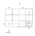
- Top view showing transported material loaded from the maintenance area side to the measurement unit
- FIG. 1 is a perspective view showing a schematic configuration of a prober 10 of the present embodiment.
- the prober 10 moves between a transported object storage unit 12, a plurality of measurement units 14, a transported object storage unit 12, and each measurement unit 14,
- at least one of the wafer and the probe card is transported into the transported object storage unit 12 or into each measurement unit 14, and the transport unit 16 is disposed between the transported object storage unit 12 and each measurement unit 14.
- a moving device 22 that is moved at the same time.
- the transported object storage unit 12 and each measurement unit 14 are arranged at regular intervals in the Y direction in a state where the surfaces accessed by the transport unit 16 face each other (that is, face-to-face).
- the transport unit 16 is disposed between the transported object storage unit 12 and each measurement unit 14.
- the conveyed product storage unit 12 includes a wafer storage unit 12a that stores a plurality of wafers and a probe card storage unit 12b that stores a plurality of probe cards.
- the number and arrangement of the transported object storage units 12 are not particularly limited.
- four transported object storage units 12 including the wafer storage unit 12a and the probe card storage unit 12b are accessed by the transport unit 16.
- each of the plurality of measurement units 14 is a rectangular parallelepiped configured by combining a plurality of frames extending in the X-axis direction, a plurality of frames extending in the Y-axis direction, and a plurality of frames extending in the Z-axis direction.
- This is a shape measurement chamber (also called a prober chamber).
- a plurality of measurement units 14 include a wafer chuck 18 that holds a wafer, a head stage 20, a test head 44 placed on the head stage 20, and a head stage.
- a first probe card holding mechanism (probe card holding part) 36 (not shown in FIGS. 9 and 10) for holding the probe card PC are arranged. ing.
- a test head lifting mechanism 48, a test head pulling mechanism 50, a pogo frame lifting mechanism 52, and a pogo frame pulling mechanism 54 are disposed inside each measurement unit 14. .
- FIG. 2 is a front view of each measurement unit 14.
- a measurement unit group including four measurement units 14 arranged in the horizontal direction (X-axis direction). Are stacked in three stages in the vertical direction (Z-axis direction), and are arranged two-dimensionally with the surface (the left surface in FIG. 1) accessed by the transport unit 16 facing the same direction.
- each measurement unit 14 surface accessed by the transfer unit 16
- a wafer holding arm 16b wafer arm: transfer object holding arm
- a probe card holding arm 16c probe card arm
- An entrance / exit 14a is formed.
- the opening 14b (refer FIG. 8) for drawing out the test head 44 and the pogo frame 46 is formed in the opposite side to the side in which the opening 14a was formed among each measurement part 14.
- FIG. Surfaces other than the surface on which the openings 14a and 14b of each measurement unit 14 are formed may be closed or an opening may be formed.
- the wafer chuck 18 is adjusted to a high or low target temperature (inspection temperature) by a known temperature adjusting device (for example, a heat plate or a chiller device built in the wafer chuck 18).
- a known temperature adjusting device for example, a heat plate or a chiller device built in the wafer chuck 18.
- the environment within each measurement unit 14 is controlled as follows. For example, the temperature in each measurement unit 14 is controlled to the target temperature (inspection temperature) by the temperature of the wafer chuck 18 disposed in each measurement unit 14.
- the humidity in each measurement unit 14 is controlled to the target humidity by purging dry air into each measurement unit 14 by a known mechanism.
- the environment in each measurement unit 14 is controlled by purging a predetermined gas (for example, nitrogen gas) into each measurement unit 14 by a known mechanism.
- Each measurement unit 14 performs a plurality of types of inspections such as a high temperature inspection, a low temperature inspection, and an inspection under a predetermined gas (for example, nitrogen gas) atmosphere.
- the environment in each measurement unit 14 is controlled so that the environment in each measurement unit 14 becomes an environment according to the inspection performed in each measurement unit 14.
- inspection implemented by each measurement part 14 may be the same between each measurement part, and may mutually differ.
- the first probe card holding mechanism 36 is a means for detachably holding the probe card PC, and is provided above the wafer chuck 18, for example, on the head stage 20 side.
- the first probe card holding mechanism 36 detachably holds the probe card PC transported to the first probe card holding mechanism 36 by a probe card transport mechanism described later. Since the first probe card holding mechanism 36 is well known (see, for example, Japanese Patent Laid-Open No. 2000-150596), further explanation is omitted.
- Each measurement unit group includes four alignment devices 38 and alignment devices 38 that perform relative alignment between the probe card PC held by the first probe card holding mechanism 36 and the wafer held by the wafer chuck 18.
- a moving device (not shown) that moves between the units 14 is arranged.
- the alignment device 38 is moved between the four measurement units 14 included in the measurement unit group in which the alignment device 38 is arranged, and is shared among the four measurement units 14.
- a moving device that moves the alignment device 38 between the four measuring units 14 for example, a device described in Japanese Patent Application Laid-Open No. 2014-150168 can be applied.
- the alignment device 38 is a means for performing relative alignment between the probe card PC held by the first probe card holding mechanism 36 and the wafer held by the wafer chuck 18.
- the alignment device 38 is a moving and rotating mechanism that moves the wafer chuck 18 such as the Z-axis movable unit 38a, the Z-axis fixed unit 38b, and the XY movable unit 38c that are moved up and down in the Z-axis direction in the XYZ- ⁇ directions. It is configured.
- the alignment device 38 mainly uses a well-known method for the probe of the probe card PC holding the wafer W held on the wafer chuck 18 while moving in the XYZ- ⁇ direction. Alignment is performed, the wafer W and the probe are brought into electrical contact, and the wafer W is used to inspect the electrical characteristics through the test head.
- the alignment device 38 holds the wafer chuck 18 in the measuring unit 14, and the probe card receiving position P1 (see FIG. 7A) near the opening 14a and the position P2 below the first probe card holding mechanism 36 (see FIG. 7B). ). That is, the alignment device 38 moves between the transport area A1 side and the maintenance area A2 side in the measurement unit 14 at the movement destination. This movement is realized by a known alignment apparatus moving device (not shown).
- the alignment device moving device moves the alignment device 38 holding the wafer chuck 18 heated to the target temperature when receiving the probe card PC to the probe card receiving position P1, and the first probe card holding mechanism 36 of the probe card PC. During the transfer to the position, the alignment device 38 holding the probe card PC and the wafer chuck 18 heated to the target temperature is moved to the position P2.
- the alignment device 38 includes a second probe card holding mechanism 40 (also referred to as a card lifter).
- the second probe card holding mechanism 40 is a means for receiving the probe card PC from the probe card holding arm 16c and holding it.
- the second probe card holding mechanism 40 includes, for example, a holding portion 40a (for example, a ring-shaped member or a plurality of pins) attached to the Z-axis movable portion 38a in a state of surrounding the wafer chuck 18, and the holding portion 40a as the Z-axis moving portion 38a.
- a lifting mechanism (not shown) that moves up and down in the Z-axis direction with respect to the shaft movable portion 38a.
- the holding unit 40a is lifted in the Z-axis direction with respect to the Z-axis movable unit 38a while the alignment device 38 is moved to the probe card receiving position P1, and the probe card PC ) And the probe card PC is lifted from the probe card holding arm 16c by the holding portion 40a rising in the Z-axis direction.
- the probe card PC is held immediately above the wafer chuck 18.
- the probe card transport mechanism is a means for transporting the probe card PC held by the second probe card holding mechanism 40 to the first probe card holding mechanism 36.
- the probe card transport mechanism is constituted by, for example, a Z-axis movable portion 38a provided in the alignment device 38 and moved up and down in the Z-axis direction.
- the conveyance of the probe card PC to the first probe card holding mechanism 36 is realized by raising the Z-axis movable part 38a in the Z-axis direction with the alignment device 38 moved to the position P2.
- FIG. 3A and 3B are perspective views of the transport unit 16, and FIG. 4 is a longitudinal sectional view illustrating a schematic configuration of the transport unit 16.
- the transfer unit 16 moves between the transfer object storage unit 12 and each measurement unit 14 in the X-axis direction and the Z-axis direction to place the wafer W or the probe card PC in the transfer object storage unit 12 or in each measurement unit 14.
- it is a housing for storing the wafer W and the probe card PC, and is a means for transporting and loading the wafer W and the probe card PC (the wafer holding arm 16b and the probe card).
- the housing 16a is provided with an opening 16f through which the card holding arm 16c) enters and exits.
- the casing 16a has a rectangular parallelepiped shape.
- a wafer holding arm 16b, a probe card holding arm 16c, an arm moving mechanism (not shown) for individually moving the arms 16b and 16c, and an environment inside the housing 16a are controlled.
- An environment control means 16d and a sensor 16e for detecting the environment in the housing 16a are arranged.
- the number of transport units 16 is not particularly limited, but in the present embodiment, one transport unit 16 is used. In FIG. 1, two transport units 16 are depicted. This is because one transport unit 16 is accessing the transport object storage unit 12 (probe card storage unit 12 b) (in the lower right in FIG. 1).
- the drawing shows the state of accessing the measurement unit 14 and the measurement unit 14 (see the conveyance unit 16 drawn on the upper left in FIG. 1).
- the wafer holding arm 16b is a means for holding the wafer W.
- the wafer holding arm 16b is arranged in the casing 16a so as to be movable in the horizontal direction along a guide rail (not shown) provided in the casing 16a. Yes.
- the wafer holding arm 16b is housed in the housing 16a together with the wafer W while holding the wafer W.
- the probe card holding arm 16c is a means for holding the probe card PC.
- the probe card holding arm 16c is disposed in the housing 16a so as to be movable in the horizontal direction along a guide rail (not shown) provided in the housing 16a.
- the probe card holding arm 16c is housed in the housing 16a together with the probe card PC while holding the probe card PC.
- the probe card PC includes a card holder CH.
- a seal ring may be included instead of the card holder CH.
- the number and arrangement of the arms 16b and 16c are not particularly limited. In this embodiment, as shown in FIG. 4, two wafer holding arms 16b and one probe card holding arm 16c are arranged in three upper and lower stages. Yes. Further, after the transport unit 16 transports the transported object to the measurement unit 14, the transport unit 16 loads the transported object into the measurement unit 14 using the arms 16b and 16c.
- the arm moving mechanism is constituted by a well-known mechanism, for example, a drive motor (not shown) provided in the housing 16a.
- a drive motor (not shown) provided in the housing 16a.
- the transport unit 16 includes air curtain forming means 42.
- the air curtain forming means 42 is a means for forming an air curtain that closes the opening 16f formed in the housing 16a so that the inside of the housing 16a is sealed or substantially sealed.
- the air curtain forming means 42 is constituted by, for example, a well-known air injection port.
- the number, shape, and arrangement of the air injection ports are not particularly limited.
- the environment in the housing 16a is controlled as follows.
- the temperature and humidity in the housing 16a are controlled to a target temperature and humidity in a predetermined gas atmosphere by purging dry air (high temperature or low temperature dry air) or a predetermined gas (nitrogen gas) into each measurement unit 14. Is done.
- This is a known environment control means 16d, for example, a temperature control gas supply source including a heater and a cooler (cooler), a blower, and a pipe line (not shown) and a pipe line (not shown) connected to the casing 16a. (Not shown).
- the environment control means 16d may include a dehumidifier.
- a gas (high-temperature or low-temperature dry air) whose temperature (and humidity) has been adjusted by a temperature-controlled gas supply source is supplied into the housing 16a through a duct by a blower, and is jetted from an air injection port.
- An air curtain that closes the opening 16f formed in 16a is formed.
- the gas supply source supplied into the housing 16a and the gas supply source injected from the air injection port may be the same or different. Surfaces other than the surface on which the opening 16f of the housing 16a is formed may be closed or an opening may be formed.
- the environment control means 16d may be attached to the housing 16a or may be attached to the arms 16b and 16c.
- the sensor 16e is a sensor that detects the environment in the housing 16a, and is, for example, a temperature sensor or a humidity sensor.
- the sensor 16e may be included in the environment control unit 16d.
- the environment control means 16d controls the environment in the housing 16a so as to be an environment according to the environment of the transport destination of the transported object. Specifically, the environment control means 16d controls the inside of the housing 16a to a target environment based on the detection result of the sensor 16e. For example, the environment control unit 16d controls the temperature control gas supply source based on the detection result of the sensor 16e so that the temperature and humidity in the housing 16a become the target temperature and humidity.
- the function of the environmental control means 16d is realized by feedback control by a controller (not shown) to which the sensor 16e and a temperature control gas supply source (heater and cooler) are electrically connected, for example.
- the environment control means 16d and the air curtain forming means 42 may be integrated.
- an air injection port may be provided downward so as to close the opening 16f, and a dry air air injection port for controlling the environment in the housing 16a may be provided.
- the air injection port of the dry air for controlling the environment in the housing 16a is provided in such a direction that the dry air to be injected circulates well in the housing 16a.
- a temperature control gas supply source including a heater and a cooler (cooler) between the environmental control means 16d and the air curtain forming means 42, And a common fan can be used.
- FIG. 5 is a perspective view of the moving device 22
- FIG. 6 is a partially enlarged perspective view of the moving device 22.
- the moving device 22 is a means for moving the transport unit 16 in the X-axis direction and the Z-axis direction between the transported object storage unit 12 and each measurement unit 14. For example, as shown in FIGS. 5 and 6, the moving device 22 moves in the horizontal direction (X-axis direction), which is the arrangement direction of each measurement unit 14, between the transported object storage unit 12 and each measurement unit 14.
- the second movable body 26 which is attached so as to be movable in the direction (Z-axis direction) and supports the transport unit 16 so as to be rotatable about the vertical axis (Z-axis) as a rotation center, and the second movable body 26 in the vertical direction (Z A second movable body moving mechanism (not shown) that moves in the axial direction), a transport unit rotating mechanism 28 that is attached to the second movable body 26 and rotates the transport unit 16 about the vertical axis (Z axis) as a rotation center. It is constituted by.
- the first movable body 24 is, for example, a frame body configured by connecting four corners of each of a pair of upper and lower rectangular frames 24a with four frames 24b extending in the Z-axis direction, and a lower portion thereof is connected to the transported object storage unit 12. It is movably connected to two guide rails 30 extending in the X-axis direction and arranged in parallel to each other on a base 34 between each measurement unit 14.
- the first movable body moving mechanism is composed of a known moving mechanism, for example, a ball screw connected to the first movable body 24, a drive motor for rotating the same (not shown), or the like. By rotating the drive motor forward and backward, the first movable body 24 (conveyance unit 16) moves along the guide rail 30 in the X-axis direction.
- the first movable body moving mechanism is a mechanism for causing the first movable body 24 to self-run, for example, a wheel provided on the first movable body 24 and a drive motor for rotating the wheel. Also good.
- the second movable body 26 is movably connected to two guide rails 32 extending in the Z-axis direction and arranged in parallel to the first movable body 24.
- the second movable body moving mechanism is composed of a known moving mechanism, for example, a ball screw connected to the second movable body 26, a drive motor for rotating the same (not shown), or the like. By rotating the drive motor forward and reverse, the second movable body 26 (conveyance unit 16) moves along the guide rail 32 in the Z-axis direction.
- the second movable body moving mechanism is a mechanism for causing the second movable body 26 to self-run, for example, a wheel provided on the second movable body 26 and a drive motor for rotating the wheel. Also good.
- the transport unit rotation mechanism 28 includes a known rotation mechanism, for example, a rotation shaft (vertical shaft) provided on the second movable body 26, a drive motor 28a for rotating the rotation shaft, and the like.
- the upper surface of the transport unit 16 is fixed to a rotation axis (vertical axis).
- the transport unit 16 rotates 180 ° about the vertical axis (Z axis), and an opening 16f formed in the transport unit 16 through which the arms 16b and 16c enter and exit is provided. It will be in the state which opposes the conveyed product storage part 12 or each measurement part 14.
- the test head 44 is a maintenance target device (a device that performs maintenance over time) used when inspecting a semiconductor element formed on a wafer, and a plurality of test heads 44 are electrically connected to the pogo pins 46 b of the pogo frame 46. Terminal (not shown).
- the test head 44 is held by a test head holding mechanism.
- the test head holding mechanism includes a base 56 and two test head guide rails 58 fixed on the base 56 and extending in the Y-axis direction.
- the test head 44 is slidably connected to the test head guide rail 58.
- the test head holding mechanism (base 56) is movably connected to a vertical guide rail (not shown) extending in the Z-axis direction.
- the base 56 is provided with a lock mechanism (not shown) for locking (fixing) the test head 44 to the base 56 (and the test head guide rail 58).
- the locking mechanism is configured by an engaging portion such as a claw portion that is engaged with or released from the test head 44, for example.
- the test head elevating mechanism 48 is a means for elevating the test head 44.
- the test head lifting mechanism 48 is configured by an actuator such as a test head cylinder (air or hydraulic cylinder), for example.
- a test head cylinder air or hydraulic cylinder
- one end of the cylinder is connected to the base 56 side, and the other end is connected to the head stage 20 side.
- the cylinder may be equipped with a brake.
- the pogo pin connection position P3 is a position where the terminal of the test head 44 and the pogo pin 46b of the pogo frame 46 are electrically connected.
- the test head lead-out position P4 is such that when the test head 44 is pulled out, the test head 44 does not come into contact with the pogo pin 46b (and the positioning pin 60a described later) of the pogo frame 46 (and there is a rising space of the pogo frame 46 described later). This is a considered position (as ensured).
- test head drawing mechanism 50 (test head slide mechanism) is a means for pulling out the test head 44 raised to the test head drawing position P4 to the maintenance area A2 side.
- the test head lead-out mechanism 50 is constituted by, for example, a test head guide rail 58.
- test head 44 raised to the test head pull-out position P4 is slid in the Y-axis direction along the test head guide rail 58 by the operator releasing the lock by the lock mechanism and pulling it forward. It is pulled out to the maintenance area A2 side through the opening 14b (see FIG. 12B). Thereby, maintenance of the test head 44 (for example, replacement of the substrate inside the test head, etc.) becomes possible.
- the test head 44 After completion of the maintenance, the test head 44 is slid in the Y-axis direction along the test head guide rail 58 to the test head pull-out position P4, and then lowered to the pogo pin connection position P3 along the vertical guide rail. . At that time, as shown in FIG. 10, the test head 44 is positioned above the pogo frame 46, that is, at the pogo pin connection position P ⁇ b> 3 while being positioned with respect to the pogo frame 46 by the test head positioning mechanism 60.
- the test head positioning mechanism 60 is a means for positioning the test head 44 with respect to the pogo frame 46.
- the test head positioning mechanism 60 includes, for example, a positioning pin 60a and a recess 60b with which the positioning pin 60a abuts.
- the positioning pin 60a may be provided on the pogo frame 46 side, or may be provided on the test head 44 side.
- the recess 60b with which the positioning pin 60a abuts is provided on the test head 44 side.
- the positioning pin 60a is provided on the test head 44 side
- the recess 60b with which the positioning pin 60a abuts is provided on the pogo frame 46 side.
- the pogo frame 46 is a maintenance target device (a device that performs maintenance over time) used when inspecting a semiconductor element formed on a wafer.
- the pogo frame 46 includes a pogo frame main body 46a and a plurality of pogo pins 46b held by the pogo frame main body 46a.
- the upper end portion of the pogo pin 46b protrudes from the upper surface of the pogo frame main body 46a, and the lower end portion of the pogo pin 46b protrudes from the lower surface of the pogo frame main body 46a.
- the pogo pin 46 b is electrically connected to the terminal of the test head 44 and is also electrically connected to the probe of the probe card PC held by the first probe card holding mechanism 36.
- the pogo frame 46 is held by a pogo frame holding mechanism.
- the pogo frame holding mechanism includes a base 62 and two pogo frame guide rails 64 fixed on the base 62 and extending in the Y-axis direction.
- the pogo frame 46 is slidably connected to the pogo frame guide rail 64.
- the pogo frame holding mechanism (base 62) is movably connected to a vertical guide rail (not shown) extending in the Z-axis direction.
- the base 62 is provided with a lock mechanism (not shown) that locks (fixes) the pogo frame 46 to the base 62 (and the pogo frame guide rail 64).
- the lock mechanism is configured by an engaging portion such as a claw portion that is engaged with or released from the pogo frame 46, for example.
- the pogo frame elevating mechanism 52 is a means for elevating the pogo frame 46.
- the pogo frame elevating mechanism 52 is configured by an actuator such as a pogo frame cylinder (air or hydraulic cylinder), for example.
- a pogo frame cylinder air or hydraulic cylinder
- one end of the cylinder is connected to the base 62 side, and the other end is connected to the head stage 20 side.
- the cylinder may be equipped with a brake.
- the probe connection position P5 is a position where the pogo pin 46b of the pogo frame 46 and the probe (not shown) of the probe card held by the first probe card holding mechanism 36 are electrically connected.
- the pogo frame drawing position P6 is a position that is considered so that the pogo frame 46 (pogo pin 46b) does not come into contact with a probe (and a positioning pin 66a described later) of the probe card when the pogo frame 46 is pulled out.
- the pogo frame drawing mechanism 54 (pogo frame sliding mechanism) is a means for pulling the pogo frame 46 raised to the pogo frame drawing position P6 to the maintenance area A2 side.
- the pogo frame drawing mechanism 54 is constituted by, for example, a pogo frame guide rail 64.
- the pogo frame 46 raised to the pogo frame pull-out position P6 is slid in the Y-axis direction along the pogo frame guide rail 64 by the operator releasing the lock by the lock mechanism and pulling it forward. It is pulled out to the maintenance area A2 side through the opening 14b (see FIG. 13B). Thereby, maintenance of the pogo frame 46 (for example, pogo pin replacement etc.) becomes possible.
- the pogo frame 46 is slid in the Y-axis direction along the pogo frame guide rail 64 to the pogo frame pull-out position P6 by the operator, and then descends to the probe connection position P5 along the vertical guide rail. .
- the pogo frame 46 is positioned above the head stage 20, that is, at the probe connection position P5 while being positioned with respect to the head stage 20 by the pogo frame positioning mechanism 66.
- the pogo frame positioning mechanism 66 is a means for positioning the pogo frame 46 with respect to the head stage 20.
- the pogo frame positioning mechanism 66 includes, for example, a positioning pin 66a and a recess 66b with which the positioning pin 66a abuts.
- the positioning pin 66a may be provided on the pogo frame 46 side, or may be provided on the head stage 20 side.
- the recess 66b with which the positioning pin 66a abuts is provided on the head stage 20 side.
- the positioning pin 66a is provided on the head stage 20 side
- the recess 66b with which the positioning pin 66a abuts is provided on the pogo frame 46 side.
- Each device and mechanism such as 52 is driven by control by a control means (controller or the like) (not shown).
- the transfer unit 16 is moved to a position where the wafer storage unit 12a can be accessed (a position where the wafer W can be taken out), and the transfer unit 16 is rotated by 180 ° to move the arms 16b and 16c in and out.
- the opening 16f formed on the wafer is opposed to the wafer storage portion 12a.
- the wafer holding arm 16b is advanced into the wafer storage unit 12a, and one wafer W is taken out from the wafer storage unit 12a and stored in the housing 16a.
- the environment in the housing 16a is controlled so as to be an environment according to the environment of the measurement unit 14 at the transport destination. Specifically, a gas whose temperature is adjusted by a temperature-controlled gas supply source is supplied into the housing 16a, and an air curtain is formed that closes the opening 16f formed in the housing 16a by being injected from the air injection port. Is done. As a result, the inside of the housing 16a is sealed or substantially sealed.
- the transfer unit 16 is moved to a position where the measurement unit 14 at the transfer destination can be accessed (position where the wafer W can be transferred), and the transfer unit 16 is rotated by 180 ° to move the arms 16b and 16c in and out.
- the opening 16f formed in the transport unit 16 is opposed to the measurement unit 14 at the transport destination.
- the wafer holding arm 16b is advanced in the Y-axis direction into the measurement unit 14 through the opening 16f on the transfer unit 16 side where the air curtain is formed and the opening 14a on the measurement unit 14 side, and the wafer chuck 18 receives the wafer. W is loaded.
- the arrow on the right side in FIG. 14 represents the transfer direction of the transfer object (wafer W here).
- the wafer holding arm 16b advances into the measurement unit 14 through the opening 16f closed by the air curtain while holding the wafer W.
- the loaded wafer W is held on the wafer chuck 18 by vacuum suction. Then, it waits until the wafer W reaches the inspection temperature by the wafer chuck 18, and when the inspection temperature is reached, the alignment device 38 moves the wafer W held on the wafer chuck 18 while moving in the XYZ- ⁇ direction.
- the probe of the probe card PC held above the chuck 18 is aligned by a known method, and then the wafer chuck 18 is moved in the Z-axis direction by the action of the alignment device 38 to electrically connect the wafer W and the probe. By bringing them into contact, the electrical characteristics of the wafer W are inspected via the pogo frame 46 (pogo pins 46b) and the test head 44.
- the environment in the transfer unit 16 is controlled using the time until the wafer is transferred from the wafer storage unit 12a to the transfer destination measurement unit 14, and the inspection temperature at the transfer destination measurement unit 14 is controlled.
- the difference it is possible to shorten (or eliminate) the waiting time for bringing the wafer close to the inspection temperature in the measurement unit 14 at the transfer destination as compared with the conventional technique.
- the throughput (processing capacity per unit time) in the measurement unit 14 can be improved.
- the transport unit 16 is moved to a position where the probe card storage unit 12b can be accessed (position where the probe card PC can be taken out), and the transport unit 16 is rotated by 180 ° so that the arms 16b and 16c enter and exit.
- the opening 16f formed in the unit 16 is opposed to the probe card storage portion 12b.
- the probe card holding arm 16c is advanced into the probe card storage unit 12b, and one probe card PC is taken out from the probe card storage unit 12b and stored in the housing 16a.
- the environment in the housing 16a is controlled so as to be an environment according to the environment of the measurement unit 14 at the transport destination. Specifically, a gas whose temperature is adjusted by a temperature-controlled gas supply source is supplied into the housing 16a, and an air curtain is formed that closes the opening 16f formed in the housing 16a by being injected from the air injection port. Is done. As a result, the inside of the housing 16a is sealed or substantially sealed.
- the transport unit 16 is moved to a position where the measurement unit 14 at the transport destination can be accessed (position where the probe card PC can be handed over), and the transport unit 16 is rotated 180 degrees so that the arms 16b and 16c enter and exit.
- the opening 16f formed in the transport unit 16 to be transported is opposed to the measurement unit 14 at the transport destination.
- the probe card holding arm 16c is advanced in the Y-axis direction into the measurement unit 14 through the opening 16f on the transport unit 16 side where the air curtain is formed and the opening 14a on the measurement unit 14 side (see FIG. 7A). While holding the probe card PC, the probe card holding arm 16c advances into the measurement unit 14 in the Y-axis direction through the opening 16f closed by the air curtain.
- the arrow on the right side in FIG. 14 represents the transport direction of the transported object (here, probe card PC).
- the probe card PC is received from the probe card holding arm 16c and held by the holding portion 40a of the second probe card holding mechanism 40.
- the holding portion 40a is raised in the Z-axis direction with respect to the Z-axis movable portion 38a to thereby move the probe card PC.
- the probe card PC is lifted from the probe card holding arm 16c by the holding portion 40a that is brought into contact with the outer peripheral edge of the lower surface and is raised in the Z-axis direction.
- the probe card PC is delivered to the holding unit 40a, and held by the holding unit 40a directly above the wafer chuck 18.
- the alignment device 38 holding the probe card PC and the wafer chuck 18 is moved to the position P2 (see FIG. 7B).
- the probe card PC is transported to the first probe card holding mechanism 36 (see FIG. 7B). Specifically, by moving the Z-axis movable portion 38a (second probe card holding mechanism 40) in the Z-axis direction while the alignment device 38 holding the wafer chuck 18 is moved to the position P2, The probe card PC held by the two-probe card holding mechanism 40 is conveyed to the first probe card holding mechanism 36. The probe card PC conveyed to the first probe card holding mechanism 36 is detachably held by the first probe card holding mechanism 36.
- test head pull-out operation Next, an operation example when the test head 44 is pulled out to the maintenance area A2 side will be described.
- the test head lifting mechanism 48 raises the test head holding mechanism (base 56) from the pogo pin connection position P3 to the test head drawing position P4.
- the test head 44 moves to the test head drawing position P4 together with the test head guide rail 58 fixed to the base 56 while being locked by the locking mechanism.
- the operator pulls the test head 44 raised to the test head pull-out position P4 to the near side.
- the test head 44 slides in the Y-axis direction along the test head guide rail 58 and is pulled out to the maintenance area A2 side through the opening 14b.
- maintenance of the test head 44 for example, replacement of the substrate inside the test head, etc.
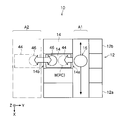
- the arrow on the left side in FIG. 14 represents the pull-out direction (and push-in direction) of the maintenance target apparatus (here, the test head 44).
- the operator pushes the test head 44 for which maintenance has been completed along the test head guide rail 58 and slides the test head 44 to the test head pull-out position P4 in the Y-axis direction, and locks by the lock mechanism at that position. .
- the test head lifting mechanism 48 lowers the test head holding mechanism (base 56) from the test head pull-out position P4 to the pogo pin connection position P3.
- the test head 44 moves to the pogo pin connection position P3 together with the test head guide rail 58 fixed to the base 56 in a locked state by the lock mechanism.
- the test head 44 is positioned above the pogo frame 46, that is, at the pogo pin connection position P ⁇ b> 3 while being positioned with respect to the pogo frame 46 by the test head positioning mechanism 60.
- the terminals of the test head 44 and the pogo pins 46b of the pogo frame 46 are aligned, so that both can be electrically connected with high accuracy.
- the pull-out direction of the maintenance target apparatus here, the test head 44
- the transfer direction of the transfer object (wafer W or probe card PC)
- the Abbe error that must be taken into account when positioning the test head 44 with respect to the pogo frame 46, which requires high accuracy, can be suppressed (or eliminated).
- the test head 44 for which maintenance has been completed is returned to the pogo pin connection position P3, it is possible to suppress a decrease in positioning accuracy in the X-axis direction.
- the test head lifting mechanism 48 raises the test head holding mechanism (base 56) from the pogo pin connection position P3 to the test head drawing position P4.
- the test head 44 moves to the test head drawing position P4 together with the test head guide rail 58 fixed to the base 56 while being locked by the locking mechanism.
- the rising space S of the pogo frame 46 is ensured.
- the pogo frame lifting mechanism 52 raises the pogo frame holding mechanism (base 62) from the probe connection position P5 to the pogo frame drawing position P6.
- the pogo frame 46 is moved to the pogo frame drawing position P6 together with the pogo frame guide rail 64 fixed to the base 62 while being locked by the locking mechanism.
- the pogo frame 46 slides in the Y-axis direction along the pogo frame guide rail 64 and is pulled out to the maintenance area A2 side through the opening 14b.
- the left arrow in FIG. 14 represents the pulling direction (and the pushing direction) of the maintenance target device (here, the pogo frame 46).
- the operator pushes the pogo frame 46 for which maintenance has been completed along the pogo frame guide rail 64 and slides the pogo frame 46 to the pogo frame pull-out position P6 in the Y-axis direction, and locks by the lock mechanism at that position. .
- the pogo frame lifting mechanism 52 lowers the pogo frame holding mechanism (base 62) from the pogo frame pull-out position P6 to the probe connection position P5.
- the pogo frame 46 is moved to the probe connection position P5 together with the pogo frame guide rail 64 fixed to the base 62 while being locked by the locking mechanism.
- the pogo frame 46 is positioned above the head stage 20, that is, at the probe connection position P5 while being positioned with respect to the head stage 20 by the pogo frame positioning mechanism 66.
- the pull-out direction of the maintenance target apparatus here, the pogo frame 46
- the transfer direction of the transfer object wafer W or probe card PC
- the arrow on the right side in FIG. 14 Therefore, it is possible to suppress (or eliminate) an Abbe error that must be taken into account when positioning the pogo frame 46 with respect to the head stage 20 for which high accuracy is required.
- the pogo frame 46 for which maintenance has been completed is returned to the probe connection position P5, it is possible to suppress a decrease in positioning accuracy in the X-axis direction.
- the pogo frame is pulled out without raising the pogo frame, so the probe card had to be carried out of the measuring unit (cell) before pulling out the pogo frame.
- the pogo frame 46 is raised to the pogo frame drawing position P6 and separated from the probe card, and then the pogo frame 46 raised to the pogo frame drawing position P6 is pulled out.
- the pogo frame 46 can be pulled out without unloading the PC from the measuring unit 14.
- a plurality of measurement units 14 including a maintenance target device (for example, at least one of a test head and a pogo frame) and a drawer mechanism that pulls out the maintenance target device
- the prober 10 includes a transfer unit 16 that moves to a position where the measurement unit of the transfer destination of at least one of the wafer and the probe card can be accessed and transfers the transferred object into the measurement unit 14 of the transfer destination.
- the pull-out direction of the maintenance target device and the conveyance direction of the transported object straight (see FIG. 14), the Abbe error that must be taken into consideration when positioning the maintenance target device that requires high accuracy is suppressed. You can do (or eliminate).
- the probe card PC is disposed on the pogo frame 46 and the wafer W is disposed on the probe card PC.
- the Abbe error can be suppressed by conveying these components that require positioning in a straight line.
- the structure which needs these positioning is conveyed in a straight line, since the positioning in a straight line can be abbreviate
- the test head is rotated to expose the pogo pin under the test head to perform a maintenance test. Space is saved as much as there is no space for rotating the head.
- test head 44 can be pulled out.
- the transfer object (wafer W or probe card PC) loaded in the measurement unit 14 is loaded from the transfer area A1 side by the transfer unit 16 (see FIG. 14).
- the conveyed product loaded in the measurement part 14 is loaded from the maintenance area A2 side by the loading part 70.
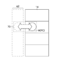
- FIG. 15 is a top view showing that the transported object (wafer W and probe card PC) is loaded into the measurement unit 14 from the maintenance area A2 side.
- the loaded unit 70 loads the conveyed product into the measurement unit 14.
- the loading unit 70 may be provided with a conveyance unit such as the conveyance unit 16 described above to convey the conveyed product, or the user or the installer of the prober 10 manually conveys the conveyed item to the loading unit 70. Then, the measuring unit 14 may be loaded by the loading unit 70.
- the loading unit 70 is not particularly limited, and a known loading unit can be employed.
- the loading unit 70 may load the conveyed product into the measurement unit by using a pull-out mechanism, or may load the conveyed product into the measurement unit by an arm like the conveyance unit 16.
- the measurement unit 14 can be loaded with a transported object from the transport area A1 side and from the maintenance area A2 side.
- the transport unit 16 loads the transported object into the measuring unit 14 when the transported object is for inspection of a semiconductor element, and the loading unit 70
- the conveyed object is loaded into the measuring unit 14.
- the transported object is loaded into the measuring unit 14 from the transport area A1 side, and the loading of the transported object into the measuring unit 14 is infrequent.
- the loaded object is loaded into the measuring unit 14 from the maintenance area side.
- the high frequency and the low frequency are different depending on how the user uses the prober 10.
- the high frequency is a transported object that needs to be replaced every time the wafer W is measured. This is a transported object that needs to be loaded at the time of installation (starting up) 10.
- the transport unit 16 loads the transported object to the measuring unit 14 when the transported object requires environmental control, and the loading unit 70 transports the transported object when the environmental control is not necessary.
- An object is loaded into the measuring unit 14.
- the transport unit 16 since environmental adjustment is performed by the environmental control means 16d of the transport unit 16 in the transport area A1, when a transported object that requires temperature adjustment or humidity adjustment is loaded into the measurement unit 14, the transported object is The measurement unit 14 is loaded from the conveyance area A1 side.
- loading by the transport unit 16 or loading by the loading unit 70 may be divided according to the type of the transported object. That is, since the wafer W and the probe card PC, which are the objects to be conveyed, have various uses and types, the loading unit 70 by the transfer unit 16 or the loading unit 70 depends on the uses and types of the wafer W and the probe card PC. The loading by may be divided.
- the probe card PC includes a measurement probe card for inspecting and measuring the wafer W and a calibration probe card for calibrating the position of the wafer W and the like.
- the calibration probe card is loaded by the loading unit 70, and the measurement probe card is loaded by the transport unit 16.
- the loading of the present application means that the probe card PC or the wafer W is installed in the measuring unit 14. Moreover, it is preferable that the loading by the conveyance unit 16 and the loading by the loading unit 70 are arranged in a straight line with respect to the pulling-out direction of the maintenance target device and the conveyance direction of the conveyance object. In addition, the arrow in FIG. 15 represents the loading direction which the loading part 70 performs.
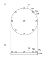
- FIG. 16 is a conceptual diagram showing an example of a calibration probe card.
- 16A is a top view of the calibration probe card 72 on the probe side
- FIG. 16B is a side view of the calibration probe card 72.
- FIG. The calibration probe card 72 shown in FIG. 16 includes a calibration probe card main body 72a and a probe 72b.
- the calibration probe card 72 has 18 probes 72b in total. Two probes 72b form a pair (one set), one set at the center, and one set at a 45 ° interval along the outer periphery of the calibration probe card 72.
- the calibration probe card 72 is used for alignment and alignment of the measurement unit 14. Therefore, for example, when the prober 10 is started up or installed, the calibration probe card 72 is used to align the measuring unit 14.
- test head lifting mechanism 48 the configuration using the test head lifting mechanism 48, the test head pulling mechanism 50, the pogo frame lifting mechanism 52, and the pogo frame pulling mechanism 54 is illustrated, but the present invention is not limited thereto, and the test head lifting mechanism 48 and Only the test head pulling mechanism 50 may be used, or only the pogo frame lifting mechanism 52 and the pogo frame pulling mechanism 54 may be used.
- the pogo frame elevating mechanism 52 is used and the pogo frame 46 that is raised by this is drawn out.
- the present invention is not limited to this, and the pogo frame elevating mechanism 52 may be omitted.
- a pogo frame pulling mechanism similar to that of the prior art may be used, and the pogo frame 46 may be pulled out without raising the pogo frame 46.
- the configuration in which the arms 16b and 16c of the transport unit 16 enter and exit through the opening 16f formed in the housing 16a is illustrated, but the present invention is not limited thereto.
- a similar opening (not shown) is formed on the surface of the casing 16a of the transport unit 16 opposite to the side where the opening 16f is formed, and the arms 16b and 16c reciprocate individually in the horizontal direction. It may be configured to move in and out through the opening 16f and the opening on the opposite side.
- the transport unit rotation mechanism 28 can be omitted. Even though the transport unit rotation mechanism 28 is omitted, that is, without the transport unit 16 being rotated, the arms 16b and 16c can access the transport object storage unit 12 or the measurement units 14.
- an air curtain that closes the opening formed on the opposite side of the opening 16f is provided.
- each measurement unit 14 is two-dimensionally arranged in the horizontal direction (X-axis direction) and the vertical direction (Z-axis direction) is illustrated, but the measurement unit 14 is not limited thereto. May be arranged only in a line in the horizontal direction (X-axis direction), or may be arranged only in a line in the vertical direction (Z-axis direction).
- the second movable body moving mechanism can be omitted by arranging the measuring units 14 in only one row in the horizontal direction (X-axis direction).
- the first movable body moving mechanism can be omitted by arranging the measuring units 14 in only one line in the vertical direction (Z-axis direction).
- the configuration using one transport unit 16 and one moving device 22 is illustrated, but the present invention is not limited to this, and a plurality of transport units 16 and a plurality of moving devices 22 may be used. In this way, the throughput in each measurement unit 14 can be further improved.
- the configuration using the wafer holding arm 16b and the probe card holding arm 16c has been exemplified.
- the configuration is not limited thereto, and only the wafer holding arm 16b may be used, or only the probe card holding arm 16c may be used. It may be used.
- each arm 16b and 16c in the conveyance unit 16 was illustrated, not only this but each arm 16b and 16c (or each on the conveyance article storage part 12 side and each measurement part 14 side) An arm corresponding to this may be provided. Also by this, it is possible to take out the conveyed product from the conveyed product storage unit 12 or the measurement unit 14 by each arm and store it in the conveyance unit 16, and to take out the conveyed product from the conveyance unit 16 and to store the conveyed product storage unit 12 or It can be delivered to the measurement unit 14.
- an opening opening / closing means such as a shutter or a door that is opened when the conveyed product is taken out or delivered and is closed during the conveyance of the conveyed product is provided in the conveyance unit 16, and the opening 16f is opened and closed by the opening opening / closing device. May be. Moreover, you may comprise so that the opening 14a formed in each measurement part 14 may be obstruct
- the pulling direction of the maintenance target device and the transport direction of the transported object are aligned so that it can be considered when positioning the maintenance target device that requires high accuracy.
- the concept of suppressing the Abbe error that must be provided is not only the prober of the above embodiment, but also a plurality of measuring units equipped with a maintenance target device and a drawer mechanism for pulling out the maintenance target device, and a measurement unit for a destination of the transported object All types of probers equipped with a transport unit that moves to a position where it can be accessed It is possible to apply.
Landscapes
- Engineering & Computer Science (AREA)
- Physics & Mathematics (AREA)
- General Physics & Mathematics (AREA)
- Computer Hardware Design (AREA)
- Microelectronics & Electronic Packaging (AREA)
- General Engineering & Computer Science (AREA)
- Environmental & Geological Engineering (AREA)
- Testing Or Measuring Of Semiconductors Or The Like (AREA)
- Testing Of Individual Semiconductor Devices (AREA)
- Automation & Control Theory (AREA)
- Manufacturing & Machinery (AREA)
- Container, Conveyance, Adherence, Positioning, Of Wafer (AREA)
Abstract
被メンテナンス装置及び被メンテナンス装置を引き出す引出機構を備えた複数の測定部と、搬送物の搬送先の測定部にアクセス可能な位置まで移動して搬送物を搬送先の測定部内に搬送する搬送ユニットと、を備えたプローバにおいて、高精度が求められる被メンテナンス装置の位置決めの際に考慮しなくてはならないアッベ誤差を抑制する。プローバ10は、測定部14と、搬送ユニット16と、メンテナンスエリアA2側から測定部に搬送物を装填する装填部70と、を備え、被メンテナンス装置の引出方向と搬送物の搬送方向とが一直線状であり、測定部14は、搬送エリアA1側及びメンテナンスエリアA2側から搬送物が装填されることが可能である。
Description
本発明は、半導体ウエハ上に形成された複数の半導体素子(チップ)の電気的特性の検査を行うプローバに関し、特に、被メンテナンス装置をメンテナンスエリア側に引き出す引出機構を備えたプローバに関する。
従来、複数の測定部(セル)と、各測定部へ搬送物(ウエハ)を搬送する搬送機構(ローダ)と、ポゴフレーム(被メンテナンス装置)を側方向に引き出す引出機構(移動機構)と、を備えたプローバ(ウエハ検査装置)が提案されている(例えば、特許文献1参照)。特許文献1に記載のプローバによれば、ポゴフレームの上方に配置されたテストヘッドを移動機構によって上昇させてポゴフレームから離間させた状態で、ポゴフレームを側方向に引き出す構成であるため、ポゴフレームを側方向へ引き出す際、ポゴフレームのポゴピンがテストヘッドと擦れることに起因するポゴピンの折損等を防止することができる。
しかしながら、特許文献1に記載のプローバにおいては、被メンテナンス装置の引出方向と搬送物の搬送方向とをどのような関係とするのが望ましいかについては一切提案されていない。
本発明は、このような事情に鑑みてなされたもので、被メンテナンス装置及び被メンテナンス装置を引き出す引出機構を備えた複数の測定部と、搬送物の搬送先の測定部にアクセス可能な位置まで移動して搬送物を搬送先の測定部内に搬送する搬送ユニットと、を備えたプローバにおいて、高精度が求められる被メンテナンス装置の位置決めの際に考慮しなくてはならないアッベ誤差を抑制すること(又は無くすこと)を目的とする。さらに本発明では、測定部への搬送物の装填が両側から行える、測定部又は搬送物の使用状況に応じて測定部への搬送物の装填方向を使い分けることができ効率の良い検査を行うことができるプローバを提供することを目的とする。
上記目的を達成するために、本発明のプローバは、搬送エリアとメンテナンスエリアとの間に配置された複数の測定部であって、ウエハ上に形成された半導体素子の検査の際に用いられる被メンテナンス装置と、被メンテナンス装置をメンテナンスエリア側に引き出す引出機構と、を備えた複数の測定部と、搬送物を収納する筐体を備え、搬送エリア内において搬送物の搬送先の測定部にアクセス可能な位置まで移動して搬送物を搬送先の測定部内に搬送して装填する搬送ユニットと、メンテナンスエリア側から測定部に搬送物を装填する装填部と、を備え、被メンテナンス装置の引出方向と搬送物の搬送方向とが一直線状であり、測定部は、搬送エリア側及びメンテナンスエリア側から搬送物が装填されることが可能である。
本態様によれば、被メンテナンス装置の引出方向と搬送物の搬送方向が一直線状であるので、被メンテナンス装置の位置決めの際に考慮しなくてはならないアッベ誤差を抑制することができる。
また本態様によれば、測定部が搬送エリア側及びメンテナンスエリア側から搬送物が装填されることが可能であるので、測定部又は搬送物の使用状況に応じて測定部への搬送物の装填方向を使い分けることができ、効率の良い検査を行うことができる。
本発明のプローバの一態様において、搬送ユニットは、搬送物が半導体素子の検査用である場合には搬送物を測定部へ装填し、装填部は、搬送物が測定部の位置の校正に用いられる場合には搬送物を測定部へ装填する。
本態様によれば、搬送ユニットは、搬送物が半導体素子の検査用である場合には搬送物を測定部へ装填し(搬送エリア側から装填)、装填部は、搬送物が測定部の位置の校正に用いられる場合には搬送物を測定部へ装填するので(メンテナンスエリア側から装填)、測定部への装填が検査用途のものと校正用途のもので装填方向を使い分けることができ、効率的な検査を行うことができる。
本発明のプローバの一態様において、搬送ユニットは、搬送物が環境の制御が必要な場合には搬送物を測定部へ装填し、装填部は、搬送物が環境の制御が必要でない場合には搬送物を測定部へ装填する。
本態様によれば、搬送ユニットは、搬送物が環境の制御が必要な場合には搬送物を測定部へ装填し(搬送エリア側から装填)、装填部は、搬送物が環境の制御が必要でない場合には搬送物を測定部へ装填するので(メンテナンスエリア側から装填)、測定部への装填が環境の制御の必要性の有無で装填方向を使い分けることができ、効率的な検査を行うことができる。
本発明のプローバの一態様において、装填部が測定部に装填する搬送物は、校正用プローブカードである。
本態様によれば、校正用プローブカードは装填部により測定部に装填されるので、効率良く測定部の校正を行うことができる。
本発明のプローバの一態様において、搬送ユニットが測定部に装填する搬送物は、測定用プローブカードである。
本態様によれば、測定用プローブカードは搬送ユニットにより測定部に装填されるので、効率良く測定部での測定を行うことができる。
本発明によれば、被メンテナンス装置及び被メンテナンス装置を引き出す引出機構を備えた複数の測定部と、搬送物の搬送先の測定部にアクセス可能な位置まで移動して搬送物を搬送先の測定部内に搬送する搬送ユニットと、を備えたプローバにおいて、高精度が求められる被メンテナンス装置の位置決めの際に考慮しなくてはならないアッベ誤差を抑制すること(又は無くすこと)ができる。
以下、添付図面に従って本発明の好ましい実施の形態について説明する。
図1は、本実施形態のプローバ10の概略構成を示す斜視図である。
図1に示すように、本実施形態のプローバ10は、搬送物収納部12と、複数の測定部14と、搬送物収納部12と各測定部14との間で移動して搬送物(本実施形態ではウエハ及びプローブカードのうち少なくとも一方)を搬送物収納部12内又は各測定部14内に搬送する搬送ユニット16と、搬送ユニット16を搬送物収納部12と各測定部14との間で移動させる移動装置22と、を備えている。
搬送物収納部12及び各測定部14は、搬送ユニット16によってアクセスされる側の面が互いに対向した状態(すなわち、向かい合わせの状態)でY方向に一定間隔をおいて配置されている。
搬送ユニット16は、搬送物収納部12と各測定部14との間に配置されている。
搬送物収納部12は、複数のウエハを収納するウエハ収納部12a及び複数のプローブカードを収納するプローブカード収納部12bを含む。搬送物収納部12の数や配置形態は特に限定されず、本実施形態では、ウエハ収納部12a及びプローブカード収納部12bを含む4つの搬送物収納部12が、搬送ユニット16によってアクセスされる側の面(図1中右側の面)を同一方向に向けた状態で水平方向(X軸方向)に配置されている。なお、搬送ユニット16によってアクセスされる側とは反対側(図1中左側)は、ウエハ又はプローブカード回収等の際に作業者によってアクセスされる。
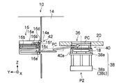
複数の測定部14は、図8に示すように、搬送エリアA1とメンテナンスエリアA2との間に配置されている。複数の測定部14は、それぞれ、図1に示すように、X軸方向に延びる複数のフレーム、Y軸方向に延びる複数のフレーム及びZ軸方向に延びる複数のフレームを組み合わせることで構成された直方体形状の測定室(プローバ室とも称される)である。複数の測定部14の内部には、図9及び図10に示すように、ウエハを保持するウエハチャック18と、ヘッドステージ20と、ヘッドステージ20上に載置されたテストヘッド44と、ヘッドステージ20とテストヘッド44との間に配置されたポゴフレーム46と、プローブカードPCを保持する第1プローブカード保持機構(プローブカード保持部)36(図9及び図10中省略)と、が配置されている。また、図11に示すように、各測定部14内部には、テストヘッド昇降機構48と、テストヘッド引出機構50と、ポゴフレーム昇降機構52と、ポゴフレーム引出機構54と、が配置されている。
図2は、各測定部14の正面図である。
測定部14の数や配置形態は特に限定されないが、本実施形態では、図1及び図2に示すように、水平方向(X軸方向)に配置された4つの測定部14からなる測定部群が鉛直方向(Z軸方向)に3段積み重ねられ、搬送ユニット16によってアクセスされる側の面(図1中左側の面)を同一方向に向けた状態で二次元的に配置されている。
各測定部14(搬送ユニット16によってアクセスされる側の面)には、搬送ユニット16のウエハ保持アーム16b(ウエハ用アーム:搬送物保持アーム)及びプローブカード保持アーム16c(プローブカード用アーム)が出入りする開口14aが形成されている。また、各測定部14のうち開口14aが形成された側とは反対側には、テストヘッド44及びポゴフレーム46を引き出すための開口14b(図8参照)が形成されている。各測定部14の開口14a及び14bが形成された面以外の面は閉塞されていてもよいし、開口が形成されていてもよい。
ウエハチャック18は、周知の温度調節装置(例えば、ウエハチャック18に内蔵されたヒートプレートやチラー装置等)により、高温又は低温の目標温度(検査温度)に調節される。
各測定部14内の環境は次のようにして制御される。例えば、各測定部14内の温度は、各測定部14内に配置されたウエハチャック18の温度によって目標温度(検査温度)に制御される。また、各測定部14内の湿度は、周知の機構によって各測定部14内に乾燥空気をパージすることによって目標湿度に制御される。また、各測定部14内の環境は、周知の機構によって各測定部14内に所定ガス(例えば、窒素ガス)をパージすることによって制御される。各測定部14では、後述の高温検査、低温検査、所定ガス(例えば、窒素ガス)雰囲気下での検査等の複数種類の検査が実施される。各測定部14内の環境は、各測定部14で実施される検査に応じた環境となるように各測定部14内の環境が制御される。なお、各測定部14で実施される検査は各測定部間で同一であってもよいし、相互に異なってもよい。
第1プローブカード保持機構36は、プローブカードPCを着脱自在に保持するための手段で、ウエハチャック18の上方、例えば、ヘッドステージ20側に設けられている。第1プローブカード保持機構36は、後述のプローブカード搬送機構によって当該第1プローブカード保持機構36まで搬送されたプローブカードPCを着脱自在に保持する。第1プローブカード保持機構36については周知である(例えば、特開2000-150596号公報参照)ため、これ以上の説明を省略する。
各測定部群には、第1プローブカード保持機構36に保持されたプローブカードPCとウエハチャック18に保持されたウエハとの相対的な位置合わせを行うアライメント装置38及びアライメント装置38を4つの測定部14間で相互に移動させる移動装置(図示せず)が配置されている。アライメント装置38は、これが配置された測定部群に含まれる4つの測定部14間で相互に移動されて、当該4つの測定部14間で共有される。アライメント装置38を4つの測定部14間で相互に移動させる移動装置については、例えば、特開2014-150168号公報に記載のものを適用することができる。
アライメント装置38は、第1プローブカード保持機構36に保持されたプローブカードPCとウエハチャック18に保持されたウエハとの相対的な位置合わせを行うための手段である。アライメント装置38は、Z軸方向に昇降されるZ軸可動部38aやZ軸固定部38bやXY可動部38c等のウエハチャック18をX-Y-Z-θ方向に移動させる移動及び回転機構で構成されている。アライメント装置38は、主に、X-Y-Z-θ方向に移動しながらウエハチャック18に保持されたウエハWをウエハチャック18上方に保持されたプローブカードPCのプローブに対して周知の方法でアライメントし、ウエハWとプローブとを電気的に接触させ、テストヘッドを介してウエハWの電気的特性検査を実施するために用いられる。
アライメント装置38は、測定部14内においてウエハチャック18を保持した状態で、開口14a近傍のプローブカード受取位置P1(図7A参照)と第1プローブカード保持機構36の下方の位置P2(図7B参照)との間で移動する。すなわち、アライメント装置38は、移動先の測定部14において、搬送エリアA1側とメンテナンスエリアA2側との間で移動する。この移動は、周知のアライメント装置移動装置(図示せず)によって実現される。
アライメント装置移動装置は、プローブカードPCの受取に際して目標温度に加熱されたウエハチャック18を保持した状態のアライメント装置38をプローブカード受取位置P1まで移動させ、プローブカードPCの第1プローブカード保持機構36への搬送に際してプローブカードPC及び目標温度に加熱されたウエハチャック18を保持した状態のアライメント装置38を位置P2まで移動させる。
アライメント装置38は、第2プローブカード保持機構40(カードリフタとも称される)を備えている。
第2プローブカード保持機構40は、プローブカード保持アーム16cからプローブカードPCを受け取り、これを保持するための手段である。第2プローブカード保持機構40は、例えば、ウエハチャック18を取り囲んだ状態でZ軸可動部38aに取り付けられた保持部40a(例えば、リング状部材又は複数のピン)と、当該保持部40aをZ軸可動部38aに対してZ軸方向に昇降させる昇降機構(図示せず)と、によって構成されている。
プローブカードPCの受け取り及び保持は、アライメント装置38がプローブカード受取位置P1に移動した状態で、保持部40aをZ軸可動部38aに対してZ軸方向に上昇させてプローブカードPC(下面外周縁)に当接させ、このZ軸方向に上昇する保持部40aでプローブカードPCをプローブカード保持アーム16cから持ち上げることで実現される。プローブカードPCは、ウエハチャック18の直上で保持される。
プローブカード搬送機構は、第2プローブカード保持機構40によって保持されたプローブカードPCを第1プローブカード保持機構36まで搬送するための手段である。プローブカード搬送機構は、例えば、アライメント装置38に設けられた、Z軸方向に昇降されるZ軸可動部38aによって構成されている。
プローブカードPCの第1プローブカード保持機構36への搬送は、アライメント装置38が位置P2に移動した状態で、Z軸可動部38aをZ軸方向に上昇させることで実現される。
図3A及び図3Bは搬送ユニット16の斜視図であり、図4は搬送ユニット16の概略構成を表す縦断面図である。
搬送ユニット16は、搬送物収納部12と各測定部14との間でX軸方向及びZ軸方向に移動してウエハW又はプローブカードPCを搬送物収納部12内又は各測定部14内に搬送し装填するための手段で、図3A、図3B及び図4に示すように、ウエハW及びプローブカードPCを収納する筐体であって、ウエハW及びプローブカードPC(ウエハ保持アーム16b及びプローブカード保持アーム16c)が出入りする開口16fが形成された筐体16aを備えている。筐体16aは、直方体形状である。筐体16aの内部には、ウエハ保持アーム16bと、プローブカード保持アーム16cと、各アーム16b及び16cを個別に移動させるアーム移動機構(図示せず)と、筐体16a内の環境を制御する環境制御手段16dと、筐体16a内の環境を検出するセンサ16eと、が配置されている。搬送ユニット16の数は特に限定されないが、本実施形態では、1つの搬送ユニット16を用いている。図1には2つの搬送ユニット16が描かれているが、これは、1つの搬送ユニット16が搬送物収納部12(プローブカード収納部12b)にアクセスしている様子(図1中右下に描かれた搬送ユニット16参照)及び測定部14にアクセスしている様子(図1中左上に描かれた搬送ユニット16参照)を表している。
ウエハ保持アーム16bは、ウエハWを保持するための手段で、例えば、筐体16a内に設けられたガイドレール(図示せず)に沿って水平方向に移動可能に筐体16a内に配置されている。ウエハ保持アーム16bは、ウエハWを保持した状態で当該ウエハWとともに筐体16a内に収納される。
プローブカード保持アーム16cは、プローブカードPCを保持するための手段である。プローブカード保持アーム16cは、例えば、筐体16a内に設けられたガイドレール(図示せず)に沿って水平方向に移動可能に筐体16a内に配置されている。プローブカード保持アーム16cは、プローブカードPCを保持した状態で当該プローブカードPCとともに筐体16a内に収納される。プローブカードPCは、カードホルダCHを含む。カードホルダCHに代えてシールリングを含む場合もある。
各アーム16b及び16cの数や配置形態は特に限定されないが、本実施形態では、図4に示すように、2つのウエハ保持アーム16b及び1つのプローブカード保持アーム16cが上下3段に配置されている。また、搬送ユニット16は測定部14に搬送物を搬送した後に各アーム16b及び16cを使用して、搬送物を測定部14に装填する。
アーム移動機構は、周知の機構、例えば、筐体16aに設けられた駆動モータ(図示せず)で構成されている。この駆動モータを正逆回転させることにより、各アーム16b及び16cは、水平方向に個別に往復移動して筐体16aに形成された開口16fを介して出入りする。
搬送ユニット16は、エアカーテン形成手段42を備えている。
エアカーテン形成手段42は、筐体16aに形成された開口16fを閉塞するエアカーテンを形成して筐体16a内を密閉又は略密閉空間とするための手段である。エアカーテン形成手段42は、例えば、周知のエア噴射口によって構成されている。
エア噴射口の数、形状及び配置形態は特に限定されないが、本実施形態では、図4に示すように、複数のエア噴射口が下向きにエア噴射する姿勢で開口16fの上端縁近傍に当該上端縁に沿って(図4中紙面に直交する方向に)配置されている。
筐体16a内の環境は次のようにして制御される。例えば、筐体16a内の温度及び湿度は、各測定部14内に乾燥空気(高温又は低温乾燥空気)又は所定ガス(窒素ガス)をパージすることによって所定ガス雰囲気下、目標温度及び湿度に制御される。これは、周知の環境制御手段16d、例えば、ヒータ及び冷却器(クーラ)を含む温調気体供給源、送風機、及び、送風機(いずれも図示せず)と筐体16aとを連結した管路(図示せず)によって実現される。環境制御手段16dは、除湿器を含んでいてもよい。温調気体供給源で温度(及び湿度)調整された気体(高温又は低温乾燥空気)は、送風機により管路を介して筐体16a内に供給されるとともに、エア噴射口から噴射されて筐体16aに形成された開口16fを閉塞するエアカーテンが形成される。これにより、筐体16a内は密閉又は略密閉された空間となる。筐体16a内に供給される気体の供給源とエア噴射口から噴射される気体の供給源は同一であってもよいし、異なっていてもよい。筐体16aの開口16fが形成された面以外の面は閉塞されていてもよいし、開口が形成されていてもよい。環境制御手段16dは、筐体16aに取り付けられていてもよいし、アーム16b及び16cに取り付けられていてもよい。
センサ16eは、筐体16a内の環境を検出するセンサで、例えば、温度センサや湿度センサである。センサ16eは、環境制御手段16dに含まれていてもよい。
環境制御手段16dは、搬送物の搬送先の環境に応じた環境となるように筐体16a内の環境を制御する。具体的には、環境制御手段16dは、センサ16eの検出結果に基づき、筐体16a内を目標の環境に制御する。例えば、環境制御手段16dは、センサ16eの検出結果に基づき、筐体16a内の温度及び湿度が目標の温度及び湿度となるように温調気体供給源を制御する。この環境制御手段16dの機能は、例えば、センサ16e及び温調気体供給源(ヒータ及び冷却器)が電気的に接続されたコントローラ(図示せず)によるフィードバック制御によって実現される。なお、環境制御手段16dとエアカーテン形成手段42とは、一体であってもよい。すなわち、一つの装置において、開口16fを塞ぐように下向きにエア噴射口が設けられ、且つ、筐体16a内の環境を制御するための乾燥空気のエア噴射口が設けられてもよい。ここで、筐体16a内の環境を制御するための乾燥空気のエア噴射口は、噴射する乾燥空気が筐体16a内でよく循環するような向きに設けられることが好ましい。環境制御手段16dとエアカーテン形成手段42とを一体にすることにより、環境制御手段16dとエアカーテン形成手段42を設けるためのスペースが少なくなり、筐体16aの空間を有効に使用することができる。また、環境制御手段16dとエアカーテン形成手段42とを一体にすることにより、環境制御手段16dとエアカーテン形成手段42との間で、ヒータ、冷却器(クーラ)を含む温調気体供給源、及び送風機などを共通にすることができる。
図5は移動装置22の斜視図であり、図6は移動装置22の部分拡大斜視図である。
移動装置22は、搬送ユニット16を搬送物収納部12と各測定部14との間でX軸方向及びZ軸方向に移動させるための手段である。移動装置22は、例えば、図5及び図6に示すように、搬送物収納部12と各測定部14との間において各測定部14の配置方向である水平方向(X軸方向)に移動する第1可動体24、第1可動体24を水平方向(X軸方向)に移動させる第1可動体移動機構(図示せず)、第1可動体24に各測定部14の配置方向である鉛直方向(Z軸方向)に移動可能に取り付けられ、かつ、搬送ユニット16を鉛直軸(Z軸)を回転中心として回転可能に支持する第2可動体26、第2可動体26を鉛直方向(Z軸方向)に移動させる第2可動体移動機構(図示せず)、第2可動体26に取り付けられ、かつ、搬送ユニット16を鉛直軸(Z軸)を回転中心として回転させる搬送ユニット回転機構28によって構成されている。
第1可動体24は、例えば、上下一対の矩形フレーム24aそれぞれの四隅をZ軸方向に延びる4本のフレーム24bで連結することで構成されたフレーム体で、その下部が搬送物収納部12と各測定部14との間のベース34上に互いに平行に配置されたX軸方向に延びる2本のガイドレール30に移動可能に連結されている。
第1可動体移動機構は、周知の移動機構、例えば、第1可動体24に連結されたボールネジやこれを回転させる駆動モータ(いずれも図示せず)等で構成されている。この駆動モータを正逆回転させることにより、第1可動体24(搬送ユニット16)は、ガイドレール30に沿ってX軸方向に移動する。もちろん、これに限らず、第1可動体移動機構は、第1可動体24を自走させるための機構、例えば、第1可動体24に設けられた車輪及びこれを回転させる駆動モータであってもよい。
第2可動体26は、第1可動体24に互いに平行に配置されたZ軸方向に延びる2本のガイドレール32に移動可能に連結されている。
第2可動体移動機構は、周知の移動機構、例えば、第2可動体26に連結されたボールネジやこれを回転させる駆動モータ(いずれも図示せず)等で構成されている。この駆動モータを正逆回転させることにより、第2可動体26(搬送ユニット16)は、ガイドレール32に沿ってZ軸方向に移動する。もちろん、これに限らず、第2可動体移動機構は、第2可動体26を自走させるための機構、例えば、第2可動体26に設けられた車輪及びこれを回転させる駆動モータであってもよい。
搬送ユニット回転機構28は、周知の回転機構、例えば、第2可動体26に設けられた回転軸(鉛直軸)及びこれを回転させる駆動モータ28a等で構成されている。搬送ユニット16は、その上面が回転軸(鉛直軸)に固定されている。この駆動モータ28aを正逆回転させることにより、搬送ユニット16は、鉛直軸(Z軸)を回転中心として180°回転し、各アーム16b及び16cが出入りする搬送ユニット16に形成された開口16fが搬送物収納部12又は各測定部14に対向した状態となる。
テストヘッド44は、ウエハ上に形成された半導体素子の検査の際に用いられる被メンテナンス装置(経時的にメンテナンスが実施される装置)で、ポゴフレーム46のポゴピン46bに電気的に接続される複数の端子(図示せず)を含む。
テストヘッド44は、テストヘッド保持機構によって保持されている。
テストヘッド保持機構は、図11に示すように、ベース56及びベース56上に固定されたY軸方向に延びる2本のテストヘッド用ガイドレール58によって構成されている。テストヘッド44は、テストヘッド用ガイドレール58にスライド移動可能に連結されている。そして、テストヘッド保持機構(ベース56)は、Z軸方向に延びる鉛直ガイドレール(図示せず)に移動可能に連結されている。ベース56には、テストヘッド44をベース56(及びテストヘッド用ガイドレール58)に対してロック(固定)するロック機構(図示せず)が設けられている。ロック機構は、例えば、テストヘッド44に対して係合し又は係合が解除される爪部等の係合部によって構成されている。
テストヘッド昇降機構48は、テストヘッド44を昇降させるための手段である。テストヘッド昇降機構48は、例えば、テストヘッド用シリンダ(エア又は油圧シリンダ)等のアクチュエータによって構成されている。シリンダは、例えば、一端がベース56側に連結され、他端がヘッドステージ20側に連結されている。シリンダはブレーキ付きであってもよい。このアクチュエータによってテストヘッド保持機構(ベース56)が鉛直ガイドレールに沿ってZ軸方向に昇降されることにより、テストヘッド44は、ロック機構によってロックされた状態でテストヘッド用ガイドレール58とともにZ軸方向に昇降されてポゴピン接続位置P3(図10参照)又はテストヘッド引出位置P4(図12A参照)に移動する。
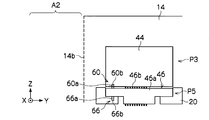
ポゴピン接続位置P3は、テストヘッド44の端子とポゴフレーム46のポゴピン46bとが電気的に接続される位置である。テストヘッド引出位置P4は、テストヘッド44を引き出す際に、テストヘッド44がポゴフレーム46のポゴピン46b(及び後述の位置決めピン60a)に接触しないように(かつ、後述のポゴフレーム46の上昇スペースが確保されるように)考慮された位置である。
テストヘッド引出機構50(テストヘッドスライド機構)は、テストヘッド引出位置P4まで上昇されたテストヘッド44をメンテナンスエリアA2側に引き出すための手段である。テストヘッド引出機構50は、例えば、テストヘッド用ガイドレール58によって構成されている。
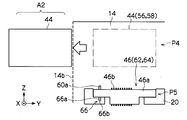
テストヘッド引出位置P4まで上昇されたテストヘッド44は、作業者がロック機構によるロックを解除してこれを手前に引き寄せることで、テストヘッド用ガイドレール58に沿ってY軸方向にスライド移動して開口14bを介してメンテナンスエリアA2側に引き出される(図12B参照)。これにより、テストヘッド44のメンテナンス(例えば、テストヘッド内部の基板交換等)が可能となる。
メンテナンスが終了したテストヘッド44は、作業者によってテストヘッド用ガイドレール58に沿ってテストヘッド引出位置P4までY軸方向にスライド移動された後、鉛直ガイドレールに沿ってポゴピン接続位置P3まで下降する。その際、テストヘッド44は、図10に示すように、テストヘッド位置決め機構60によってポゴフレーム46に対して位置決めされた状態で当該ポゴフレーム46の上方、すなわち、ポゴピン接続位置P3に配置される。
テストヘッド位置決め機構60は、テストヘッド44をポゴフレーム46に対して位置決めするための手段である。テストヘッド位置決め機構60は、例えば、位置決めピン60a及び当該位置決めピン60aが当接する凹部60bによって構成されている。位置決めピン60aは、ポゴフレーム46側に設けられていてもよいし、テストヘッド44側に設けられていてもよい。位置決めピン60aがポゴフレーム46側に設けられている場合、位置決めピン60aが当接する凹部60bは、テストヘッド44側に設けられる。一方、これとは逆に、位置決めピン60aがテストヘッド44側に設けられている場合、位置決めピン60aが当接する凹部60bは、ポゴフレーム46側に設けられる。
ポゴフレーム46は、ウエハ上に形成された半導体素子の検査の際に用いられる被メンテナンス装置(経時的にメンテナンスが実施される装置)である。ポゴフレーム46は、図10に示すように、ポゴフレーム本体46aと当該ポゴフレーム本体46aに保持された複数のポゴピン46bによって構成されている。ポゴピン46bの上端部はポゴフレーム本体46aの上面から突出しており、ポゴピン46bの下端部はポゴフレーム本体46aの下面から突出している。ポゴピン46bは、テストヘッド44の端子に電気的に接続されるとともに、第1プローブカード保持機構36によって保持されたプローブカードPCのプローブに電気的に接続される。
ポゴフレーム46は、ポゴフレーム保持機構によって保持されている。
ポゴフレーム保持機構は、図11に示すように、ベース62及びベース62上に固定されたY軸方向に延びる2本のポゴフレーム用ガイドレール64によって構成されている。ポゴフレーム46は、ポゴフレーム用ガイドレール64にスライド移動可能に連結されている。そして、ポゴフレーム保持機構(ベース62)は、Z軸方向に延びる鉛直ガイドレール(図示せず)に移動可能に連結されている。ベース62には、ポゴフレーム46をベース62(及びポゴフレーム用ガイドレール64)に対してロック(固定)するロック機構(図示せず)が設けられている。ロック機構は、例えば、ポゴフレーム46に対して係合し又は係合が解除される爪部等の係合部によって構成されている。
ポゴフレーム昇降機構52は、ポゴフレーム46を昇降させるための手段である。ポゴフレーム昇降機構52は、例えば、ポゴフレーム用シリンダ(エア又は油圧シリンダ)等のアクチュエータによって構成されている。シリンダは、例えば、一端がベース62側に連結され、他端がヘッドステージ20側に連結されている。シリンダはブレーキ付きであってもよい。このアクチュエータによってポゴフレーム保持機構(ベース62)が鉛直ガイドレールに沿ってZ軸方向に昇降されることにより、ポゴフレーム46は、ロック機構によってロックされた状態でポゴフレーム用ガイドレール64とともにZ軸方向に昇降されてプローブ接続位置P5(図12A参照)又はポゴフレーム引出位置P6(図13A参照)に移動する。
プローブ接続位置P5は、ポゴフレーム46のポゴピン46bと第1プローブカード保持機構36に保持されたプローブカードのプローブ(図示せず)とが電気的に接続される位置である。ポゴフレーム引出位置P6は、ポゴフレーム46を引き出す際に、ポゴフレーム46(ポゴピン46b)がプローブカードのプローブ(及び後述の位置決めピン66a)に接触しないように考慮された位置である。
ポゴフレーム引出機構54(ポゴフレームスライド機構)は、ポゴフレーム引出位置P6まで上昇されたポゴフレーム46をメンテナンスエリアA2側に引き出すための手段である。ポゴフレーム引出機構54は、例えば、ポゴフレーム用ガイドレール64によって構成されている。
ポゴフレーム引出位置P6まで上昇されたポゴフレーム46は、作業者がロック機構によるロックを解除してこれを手前に引き寄せることで、ポゴフレーム用ガイドレール64に沿ってY軸方向にスライド移動して開口14bを介してメンテナンスエリアA2側に引き出される(図13B参照)。これにより、ポゴフレーム46のメンテナンス(例えば、ポゴピン交換等)が可能となる。
メンテナンスが終了したポゴフレーム46は、作業者によってポゴフレーム用ガイドレール64に沿ってポゴフレーム引出位置P6までY軸方向にスライド移動された後、鉛直ガイドレールに沿ってプローブ接続位置P5まで下降する。その際、ポゴフレーム46は、図12Aに示すように、ポゴフレーム位置決め機構66によってヘッドステージ20に対して位置決めされた状態で当該ヘッドステージ20の上方、すなわち、プローブ接続位置P5に配置される。
ポゴフレーム位置決め機構66は、ポゴフレーム46をヘッドステージ20に対して位置決めするための手段である。ポゴフレーム位置決め機構66は、例えば、位置決めピン66a及び当該位置決めピン66aが当接する凹部66bによって構成されている。位置決めピン66aは、ポゴフレーム46側に設けられていてもよいし、ヘッドステージ20側に設けられていてもよい。位置決めピン66aがポゴフレーム46側に設けられている場合、位置決めピン66aが当接する凹部66bは、ヘッドステージ20側に設けられる。一方、これとは逆に、位置決めピン66aがヘッドステージ20側に設けられている場合、位置決めピン66aが当接する凹部66bは、ポゴフレーム46側に設けられる。
なお、アライメント装置38、アーム移動機構、環境制御手段16d、移動装置22(第1可動体移動機構、第2可動体移動機構、搬送ユニット回転機構28)、テストヘッド昇降機構48、ポゴフレーム昇降機構52等の各装置、機構は、不図示の制御手段(コントローラ等)による制御によって駆動される。
次に、本実施形態のプローバ10における搬送ユニット16の動作例について説明する。
<ウエハ搬送動作例>
まず、搬送ユニット16がウエハWをウエハ収納部12aから検査(例えば、高温検査又は低温検査)が実施される測定部14内に搬送する場合の動作例について説明する。
まず、搬送ユニット16がウエハWをウエハ収納部12aから検査(例えば、高温検査又は低温検査)が実施される測定部14内に搬送する場合の動作例について説明する。
まず、ウエハ収納部12aにアクセス可能な位置(ウエハWを取り出し可能な位置)まで搬送ユニット16を移動させ、かつ、搬送ユニット16を180°回転させて各アーム16b及び16cが出入りする搬送ユニット16に形成された開口16fをウエハ収納部12aに対向させる。
次に、ウエハ保持アーム16bをウエハ収納部12a内に進出させて当該ウエハ収納部12aから1枚のウエハWを取り出し、筐体16a内に収納する。これとともに、搬送先の測定部14の環境に応じた環境となるように筐体16a内の環境が制御される。具体的には、温調気体供給源で温度調整された気体が筐体16a内に供給されるとともに、エア噴射口から噴射されて筐体16aに形成された開口16fを閉塞するエアカーテンが形成される。これにより、筐体16a内が密閉又は略密閉空間とされる。
次に、搬送先の測定部14にアクセス可能な位置(ウエハWを引き渡し可能な位置)まで搬送ユニット16を移動させ、かつ、搬送ユニット16を180°回転させて各アーム16b及び16cが出入りする搬送ユニット16に形成された開口16fを搬送先の測定部14に対向させる。
次に、ウエハ保持アーム16bを、エアカーテンが形成された搬送ユニット16側の開口16f及び測定部14側の開口14aを介して測定部14内にY軸方向に進出させてウエハチャック18にウエハWを装填(ロード)する。図14中の右側の矢印は搬送物(ここではウエハW)の搬送方向を表している。ウエハ保持アーム16bは、ウエハWを保持した状態で、エアカーテンで閉塞された状態の開口16fを通過して測定部14内に進出する。
装填(ロード)されたウエハWは、真空吸着によりウエハチャック18に保持される。そして、ウエハWがウエハチャック18によって検査温度に達するまで待機し、検査温度に達すると、アライメント装置38がX-Y-Z-θ方向に移動しながらウエハチャック18に保持されたウエハWをウエハチャック18上方に保持されたプローブカードPCのプローブに対して周知の方法でアライメントし、次いで、ウエハチャック18がアライメント装置38の作用によってZ軸方向に移動してウエハWとプローブとを電気的に接触させることで、ポゴフレーム46(ポゴピン46b)及びテストヘッド44を介してウエハWの電気的特性検査が実施される。
このように、ウエハ収納部12aから搬送先の測定部14内にウエハを搬送するまでの時間を利用して搬送ユニット16内の環境を制御して搬送先の測定部14での検査温度との差を少なくすることにより、従来技術と比べ、搬送先の測定部14内でウエハを検査温度に近づけるための待機時間を短縮する(又は無くす)ことができる。これにより、測定部14でのスループット(単位時間あたりの処理能力)を向上させることができる。
<プローブカード搬送動作例>
次に、搬送ユニット16がプローブカードPCをプローブカード収納部12bから検査(例えば、高温検査又は低温検査)が実施される測定部14内に搬送する場合の動作例について説明する。
次に、搬送ユニット16がプローブカードPCをプローブカード収納部12bから検査(例えば、高温検査又は低温検査)が実施される測定部14内に搬送する場合の動作例について説明する。
まず、プローブカード収納部12bにアクセス可能な位置(プローブカードPCを取り出し可能な位置)まで搬送ユニット16を移動させ、かつ、搬送ユニット16を180°回転させて各アーム16b及び16cが出入りする搬送ユニット16に形成された開口16fをプローブカード収納部12bに対向させる。
次に、プローブカード保持アーム16cをプローブカード収納部12b内に進出させて当該プローブカード収納部12bから1枚のプローブカードPCを取り出し、筐体16a内に収納する。これとともに、搬送先の測定部14の環境に応じた環境となるように筐体16a内の環境が制御される。具体的には、温調気体供給源で温度調整された気体が筐体16a内に供給されるとともに、エア噴射口から噴射されて筐体16aに形成された開口16fを閉塞するエアカーテンが形成される。これにより、筐体16a内が密閉又は略密閉空間とされる。
次に、搬送先の測定部14にアクセス可能な位置(プローブカードPCを引き渡し可能な位置)まで搬送ユニット16を移動させ、かつ、搬送ユニット16を180°回転させて各アーム16b及び16cが出入りする搬送ユニット16に形成された開口16fを搬送先の測定部14に対向させる。
次に、プローブカード保持アーム16cをエアカーテンが形成された搬送ユニット16側の開口16f及び測定部14側の開口14aを介して測定部14内にY軸方向に進出させる(図7A参照)。プローブカード保持アーム16cは、プローブカードPCを保持した状態で、エアカーテンで閉塞された状態の開口16fを通過して測定部14内にY軸方向に進出する。図14中の右側の矢印は搬送物(ここではプローブカードPC)の搬送方向を表している。
次に、第2プローブカード保持機構40の保持部40aによって、プローブカード保持アーム16cからプローブカードPCを受け取り、これを保持させる。具体的には、ウエハチャック18を保持した状態のアライメント装置38がプローブカード受取位置P1に移動した状態で、保持部40aをZ軸可動部38aに対してZ軸方向に上昇させてプローブカードPC(下面外周縁)に当接させ、このZ軸方向に上昇する保持部40aでプローブカードPCをプローブカード保持アーム16cから持ち上げる。これにより、プローブカードPCは、保持部40aに受け渡され、当該保持部40aによってウエハチャック18の直上で保持される。
次に、プローブカードPC及びウエハチャック18を保持した状態のアライメント装置38を位置P2まで移動させる(図7B参照)。
次に、プローブカードPCを第1プローブカード保持機構36まで搬送する(図7B参照)。具体的には、ウエハチャック18を保持した状態のアライメント装置38が位置P2に移動した状態で、Z軸可動部38a(第2プローブカード保持機構40)をZ軸方向に上昇させることで、第2プローブカード保持機構40によって保持されたプローブカードPCを第1プローブカード保持機構36まで搬送する。第1プローブカード保持機構36まで搬送されたプローブカードPCは、当該第1プローブカード保持機構36によって着脱自在に保持される。
<テストヘッド引出動作例>
次に、テストヘッド44をメンテナンスエリアA2側に引き出す場合の動作例について説明する。
次に、テストヘッド44をメンテナンスエリアA2側に引き出す場合の動作例について説明する。
まず、図12Aに示すように、テストヘッド昇降機構48によって、テストヘッド保持機構(ベース56)をポゴピン接続位置P3からテストヘッド引出位置P4に上昇させる。これにより、テストヘッド44は、ロック機構によってロックされた状態で、ベース56に固定されたテストヘッド用ガイドレール58とともに、テストヘッド引出位置P4に移動する。
次に、作業者が、ロック機構によるロックを解除した後、テストヘッド引出位置P4まで上昇されたテストヘッド44を手前に引き寄せる。これにより、テストヘッド44は、図12Bに示すように、テストヘッド用ガイドレール58に沿ってY軸方向にスライド移動して開口14bを介してメンテナンスエリアA2側に引き出される。これにより、テストヘッド44のメンテナンス(例えば、テストヘッド内部の基板交換等)が可能となる。図14中の左側の矢印は被メンテナンス装置(ここではテストヘッド44)の引出方向(及び押入方向)を表している。
次に、メンテナンスが終了したテストヘッド44をポゴピン接続位置P3に戻す場合の動作例について説明する。
まず、作業者が、メンテナンスが終了したテストヘッド44をテストヘッド用ガイドレール58に沿って押し込んでテストヘッド引出位置P4までY軸方向にスライド移動させ、その位置において、ロック機構によるロックを実施する。
次に、テストヘッド昇降機構48によって、テストヘッド保持機構(ベース56)をテストヘッド引出位置P4からポゴピン接続位置P3に下降させる。これにより、テストヘッド44は、ロック機構によってロックされた状態で、ベース56に固定されたテストヘッド用ガイドレール58とともに、ポゴピン接続位置P3に移動する。その際、テストヘッド44は、図10に示すように、テストヘッド位置決め機構60によってポゴフレーム46に対して位置決めされた状態で当該ポゴフレーム46の上方、すなわち、ポゴピン接続位置P3に配置される。これにより、テストヘッド44の端子とポゴフレーム46のポゴピン46bとの位置合わせが実施されるため、両者を精度良く電気的に接続することができる。
以上のように、被メンテナンス装置(ここではテストヘッド44)の引出方向(図14中の左側の矢印参照)と搬送物(ウエハW又はプローブカードPC)の搬送方向(図14中の右側の矢印参照)とがY軸方向に関し一直線状であるため、高精度が求められるテストヘッド44のポゴフレーム46に対する位置決めの際に考慮しなくてはならないアッベ誤差を抑制すること(又は無くすこと)ができる。特に、メンテナンスが終了したテストヘッド44をポゴピン接続位置P3に戻す場合に、X軸方向に関する位置決めの精度が低下することを抑制することができる。
<ポゴフレーム引出動作例>
次に、ポゴフレーム46をメンテナンスエリアA2側に引き出す場合の動作例について説明する。
次に、ポゴフレーム46をメンテナンスエリアA2側に引き出す場合の動作例について説明する。
まず、図12Aに示すように、テストヘッド昇降機構48によって、テストヘッド保持機構(ベース56)をポゴピン接続位置P3からテストヘッド引出位置P4に上昇させる。これにより、テストヘッド44は、ロック機構によってロックされた状態で、ベース56に固定されたテストヘッド用ガイドレール58とともに、テストヘッド引出位置P4に移動する。これにより、ポゴフレーム46の上昇スペースSが確保される。
次に、図13Aに示すように、ポゴフレーム昇降機構52によって、ポゴフレーム保持機構(ベース62)をプローブ接続位置P5からポゴフレーム引出位置P6に上昇させる。これにより、ポゴフレーム46は、ロック機構によってロックされた状態で、ベース62に固定されたポゴフレーム用ガイドレール64とともに、ポゴフレーム引出位置P6に移動する。
次に、作業者が、ロック機構によるロックを解除した後、ポゴフレーム引出位置P6まで上昇されたポゴフレーム46を手前に引き寄せる。これにより、ポゴフレーム46は、図13Bに示すように、ポゴフレーム用ガイドレール64に沿ってY軸方向にスライド移動して開口14bを介してメンテナンスエリアA2側に引き出される。これにより、ポゴフレーム46のメンテナンス(例えば、ポゴピン交換等)が可能となる。図14中の左側の矢印は被メンテナンス装置(ここでポゴフレーム46)の引出方向(及び押入方向)を表している。
次に、メンテナンスが終了したポゴフレーム46をプローブ接続位置P5に戻す場合の動作例について説明する。
まず、作業者が、メンテナンスが終了したポゴフレーム46をポゴフレーム用ガイドレール64に沿って押し込んでポゴフレーム引出位置P6までY軸方向にスライド移動させ、その位置において、ロック機構によるロックを実施する。
次に、ポゴフレーム昇降機構52によって、ポゴフレーム保持機構(ベース62)をポゴフレーム引出位置P6からプローブ接続位置P5に下降させる。これにより、ポゴフレーム46は、ロック機構によってロックされた状態で、ベース62に固定されたポゴフレーム用ガイドレール64とともに、プローブ接続位置P5に移動する。その際、ポゴフレーム46は、図12Aに示すように、ポゴフレーム位置決め機構66によってヘッドステージ20に対して位置決めされた状態で当該ヘッドステージ20の上方、すなわち、プローブ接続位置P5に配置される。これにより、ポゴフレーム46のポゴピン46bとプローブカードのプローブとの位置合わせが実施されるため、両者を精度良く電気的に接続することができる。
以上のように、被メンテナンス装置(ここではポゴフレーム46)の引出方向(図14中の左側の矢印参照)と搬送物(ウエハW又はプローブカードPC)の搬送方向(図14中の右側の矢印参照)とがY軸方向に関し一直線状であるため、高精度が求められるポゴフレーム46のヘッドステージ20に対する位置決めの際に考慮しなくてはならないアッベ誤差を抑制すること(又は無くすこと)ができる。特に、メンテナンスが終了したポゴフレーム46をプローブ接続位置P5に戻す場合に、X軸方向に関する位置決めの精度が低下することを抑制することができる。
また、従来技術においては、ポゴフレームを上昇させることなくポゴフレームを引き出す構成であるため、ポゴフレームを引き出す前に、プローブカードを測定部(セル)から搬出しなければならなかったのに対して、本実施形態においては、ポゴフレーム46をポゴフレーム引出位置P6まで上昇させてプローブカードから離間させた後、当該ポゴフレーム引出位置P6まで上昇されたポゴフレーム46を引き出す構成であるため、プローブカードPCを測定部14から搬出することなく、ポゴフレーム46を引き出すことができる。
以上説明したように、本実施形態によれば、被メンテナンス装置(例えば、テストヘッド及びポゴフレームのうち少なくとも一方)及び被メンテナンス装置を引き出す引出機構を備えた複数の測定部14と、搬送物(例えば、ウエハ及びプローブカードのうち少なくとも一方)の搬送先の測定部にアクセス可能な位置まで移動して搬送物を搬送先の測定部14内に搬送する搬送ユニット16と、を備えたプローバ10において、被メンテナンス装置の引出方向と搬送物の搬送方向とを一直線状とすることで(図14参照)、高精度が求められる被メンテナンス装置の位置決めの際に考慮しなくてはならないアッベ誤差を抑制すること(又は無くすこと)ができる。
すなわち、テストヘッド44がポゴピン接続位置P3に配置され、かつ、ポゴフレーム46がプローブ接続位置P5に配置された状態で、ポゴフレーム46に対してプローブカードPCを、プローブカードPCに対してウエハWを位置決めする必要があるが、これら位置決めが必要な構成を一直線状に搬送することで、アッベ誤差を抑制できる。また本実施形態では、これら位置決めが必要な構成を一直線状に搬送することで、一直線状における位置決めは省略することができるので、より位置決めが容易となる。また本実施形態では、被メンテナンス装置の引出方向と搬送物の搬送方向とが一直線状であるので、テストヘッドを回動させてテストヘッド下のポゴピンを暴露させてメンテナンスを行う技術に対してテストヘッドの回動スペースが無い分だけ、省スペースである。
また、従来技術においては、テストヘッドを引き出す引出機構を備えておらず、テストヘッドを引き出すことができなかったのに対して、本実施形態においては、テストヘッド昇降機構48及びテストヘッド引出機構50を備えており、これによって、テストヘッド44を引き出すことができる。
次に、測定部14に装填(ロード)される他の態様に関して説明する。上述した例では、測定部14に装填される搬送物(ウエハW又はプローブカードPC)は、搬送ユニット16により搬送エリアA1側から装填されることを説明したが(図14を参照)、測定部14に装填される他の態様では、測定部14に装填される搬送物は、装填部70によりメンテナンスエリアA2側から装填される。
図15は、測定部14にメンテナンスエリアA2側から搬送物(ウエハW及びプローブカードPC)が装填されることを表す上面図である。図15に示されるように、測定部14にメンテナンスエリアA2側から搬送物が装填される場合には、装填部70により測定部14に搬送物が装填される。装填部70には、上述した搬送ユニット16のような搬送手段を設けて搬送物を搬送してもよいし、プローバ10のユーザ又は設置者が手動により、搬送物を装填部70に搬送して、その後装填部70により測定部14に装填してもよい。装填部70は、特に限定されるものではなく公知の装填手段を採用することができる。例えば装填部70は、引出機構により搬送物を測定部へ装填してもよいし、搬送ユニット16のようにアームにより搬送物を測定部へ装填してもよい。
このように、測定部14には、搬送エリアA1側から及びメンテナンスエリアA2側から、搬送物を装填することが可能である。例えば、プローブカードPCを測定部14に装填する場合には、搬送ユニット16は、搬送物が半導体素子の検査用である場合には搬送物を測定部14へ装填し、装填部70は、搬送物が測定部14の位置の校正に用いられる場合には搬送物を測定部14へ装填する。
また例えば、搬送物の測定部14への装填が高頻度である場合は、搬送物は搬送エリアA1側から測定部14へ装填され、搬送物の測定部14への装填が低頻度である場合は、搬送物はメンテナンスエリア側から測定部14へ装填される。ここで、高頻度及び低頻度はユーザのプローバ10の使用態様によって異なるものであるが、例えば高頻度はウエハWの測定時に毎回交換が必要な搬送物であり、低頻度は例えばメンテナンス時又はプローバ10の設置時(立ち上げ時)に装填が必要な搬送物である。
また例えば、搬送ユニット16は、環境の制御が必要な搬送物である場合には搬送物を測定部14へ装填し、装填部70は、環境の制御が必要でない搬送物である場合には搬送物を測定部14へ装填する。上述したように、搬送エリアA1においては搬送ユニット16の環境制御手段16dにより環境調整が行われるので、温度調整又は湿度調整が必要な搬送物を測定部14へ装填する場合には、搬送物は測定部14に搬送エリアA1側から装填される。
また例えば、搬送物の種類に応じて搬送ユニット16による装填又は装填部70による装填を分けてもよい。すなわち、搬送物であるウエハW及びプローブカードPCは様々な用途及び種類のものが使用されるので、そのウエハW及びプローブカードPCの用途及び種類に応じて、搬送ユニット16による装填又は装填部70による装填を分けてもよい。
例えば、プローブカードPCには、ウエハWの検査測定を行うための測定用プローブカード及びウエハW等の位置の校正を行う校正用プローブカードがある。そして、例えば校正用プローブカードは装填部70により装填され、測定用プローブカードは搬送ユニット16により装填される。
このように、搬送物及びプローバ10の使用状況に応じて、測定部14への搬送物の装填する側を変えることによって、より効率のよい検査を行うことができる。
ここで本願の装填とは、プローブカードPC又はウエハWを測定部14に装置することである。また、上述した搬送ユニット16による装填及び装填部70による装填は、被メンテナンス装置の引出方向及び搬送物の搬送方向に対して一直線状に配置されていることが好ましい。なお、図15中の矢印は装填部70が行う装填方向を表している。
図16は、校正用プローブカードの一例を示す概念図である。図16の(A)部は校正用プローブカード72のプローブ側の上面図であり、図16の(B)部は校正用プローブカード72の側面図である。図16に示された校正用プローブカード72は、校正用プローブカード本体72aとプローブ72bから構成されている。校正用プローブカード72は、全体で18本のプローブ72bを有する。プローブ72bは2本で対(一組)になり、中心に一組、及び、校正用プローブカード72の外周に沿って45°間隔で一組ずつ配置されている。校正用プローブカード72は、測定部14の位置合わせ、アライメントに用いられる。したがって、例えばプローバ10の立ち上げ時又は設置時に校正用プローブカード72を使用して測定部14の位置合わせを行う。
次に、変形例について説明する。
本実施形態では、テストヘッド昇降機構48、テストヘッド引出機構50、ポゴフレーム昇降機構52、及び、ポゴフレーム引出機構54を用いた構成を例示したが、これに限らず、テストヘッド昇降機構48及びテストヘッド引出機構50のみを用いてもよいし、ポゴフレーム昇降機構52及びポゴフレーム引出機構54のみを用いてもよい。
また、本実施形態では、ポゴフレーム昇降機構52を用い、これによって上昇された状態のポゴフレーム46を引き出す構成を例示したが、これに限らず、ポゴフレーム昇降機構52を省略してもよい。すなわち、従来技術と同様のポゴフレーム引出機構を用い、ポゴフレーム46を上昇させることなくポゴフレーム46を引き出すように構成してもよい。
また、本実施形態では、搬送ユニット16の各アーム16b及び16cが筐体16aに形成された開口16fを介して出入りする構成を例示したが、これに限らない。例えば、搬送ユニット16の筐体16aのうち開口16fが形成された側とは反対側の面に同様の開口(図示せず)を形成し、各アーム16b及び16cが、水平方向に個別に往復移動して開口16f及びその反対側の開口を介して出入りするように構成してもよい。このようにすれば、搬送ユニット回転機構28を省略することができる。そして、搬送ユニット回転機構28を省略したにもかかわらず、すなわち、搬送ユニット16を回転させることなく、各アーム16b及び16cによる搬送物収納部12又は各測定部14へのアクセスを実現できる。この場合、搬送ユニット16の筐体16aに形成された開口16fを閉塞するエアカーテンを形成するエアカーテン形成手段42に加えて、当該開口16fの反対側に形成された開口を閉塞するエアカーテンを形成する同様のエアカーテン形成手段を搬送ユニット16に設けることで、筐体16a内を密閉又は略密閉空間とすることができ、上記実施形態と同様の効果を奏することができる。
また、本実施形態では、各測定部14が水平方向(X軸方向)及び鉛直方向(Z軸方向)に二次元的に配置された構成を例示したが、これに限らず、各測定部14は、水平方向(X軸方向)に一列にのみ配置されていてもよいし、鉛直方向(Z軸方向)に一列にのみ配置されていてもよい。各測定部14を水平方向(X軸方向)に一列にのみ配置することで、第2可動体移動機構を省略できる。また、各測定部14を鉛直方向(Z軸方向)に一列にのみ配置することで、第1可動体移動機構を省略できる。
また、本実施形態では、1つの搬送ユニット16及び1つの移動装置22を用いた構成を例示したが、これに限らず、複数の搬送ユニット16及び複数の移動装置22を用いてもよい。このようにすれば、各測定部14でのスループットをさらに向上させることができる。
また、本実施形態では、ウエハ保持アーム16b及びプローブカード保持アーム16cを用いた構成を例示したが、これに限らず、ウエハ保持アーム16bのみを用いてもよいし、プローブカード保持アーム16cのみを用いてもよい。
また、本実施形態では、搬送ユニット16に各アーム16b及び16cを設けた構成を例示したが、これに限らず、搬送物収納部12側及び各測定部14側に各アーム16b及び16c(又はこれに相当するアーム)を設けてもよい。これによっても、各アームによって搬送物収納部12又は測定部14から搬送物を取り出して搬送ユニット16内に収納することができ、かつ、搬送ユニット16から搬送物を取り出して搬送物収納部12又は測定部14に引き渡すことができる。
また、本実施形態では、筐体16aに形成された開口16fをエアカーテンで閉塞する構成を例示したが、これに限らない。搬送物の取り出しの際又は引き渡しの際に開かれ、搬送物の搬送中に閉じられるシャッターや扉等の開口開閉手段を搬送ユニット16に設け、この開口開閉手段によって開口16fを開閉するように構成してもよい。また、各測定部14に形成された開口14aを同様のエアカーテンで閉塞するように構成してもよいし、または、同様の開口開閉手段で開口14aを開閉するように構成してもよい。
以上説明したように、被メンテナンス装置及び被メンテナンス装置を引き出す引出機構を備えた複数の測定部と、搬送物の搬送先の測定部にアクセス可能な位置まで移動して搬送物を搬送先の測定部内に搬送する搬送ユニットと、を備えたプローバにおいて、被メンテナンス装置の引出方向と搬送物の搬送方向とを一直線状とすることで、高精度が求められる被メンテナンス装置の位置決めの際に考慮しなくてはならないアッベ誤差を抑制するという考え方は、上記実施形態のプローバのみならず、被メンテナンス装置及び被メンテナンス装置を引き出す引出機構を備えた複数の測定部と、搬送物の搬送先の測定部にアクセス可能な位置まで移動して搬送物を搬送先の測定部内に搬送する搬送ユニットと、を備えたあらゆる種類のプローバに適用することができる。
以上、本発明のプローバについて詳細に説明したが、本発明は、以上の例には限定されず、本発明の要旨を逸脱しない範囲において、各種の改良や変形を行ってもよいのはもちろんである。
10…プローバ、12…搬送物収納部、12a…ウエハ収納部、12b…プローブカード収納部、14…測定部、14a…開口、16…搬送ユニット、16a…筐体、16b…ウエハ保持アーム、16c…プローブカード保持アーム、16d…環境制御手段、16e…センサ、16f…開口、18…ウエハチャック、20…ヘッドステージ、22…移動装置、24…第1可動体、26…第2可動体、28…搬送ユニット回転機構、28a…駆動モータ、30、32…ガイドレール、34…ベース、36…第1プローブカード保持機構、38…アライメント装置、40…第2プローブカード保持機構、40a…保持部、42…エアカーテン形成手段、44…テストヘッド、46…ポゴフレーム、46a…ポゴフレーム本体、46b…ポゴピン、48…テストヘッド昇降機構、50…テストヘッド引出機構、52…ポゴフレーム昇降機構、54…ポゴフレーム引出機構、56…ベース、58…テストヘッド用ガイドレール、60…テストヘッド位置決め機構、60a…位置決めピン、60b…凹部、62…ベース、64…ポゴフレーム用ガイドレール、66…ポゴフレーム位置決め機構、66a…位置決めピン、66b…凹部、CH…カードホルダ、PC…プローブカード、W…ウエハ
Claims (5)
- 搬送エリアとメンテナンスエリアとの間に配置された複数の測定部であって、ウエハ上に形成された半導体素子の検査の際に用いられる被メンテナンス装置と、前記被メンテナンス装置を前記メンテナンスエリア側に引き出す引出機構と、を備えた複数の測定部と、
搬送物を収納する筐体を備え、前記搬送エリア内において前記搬送物の搬送先の測定部にアクセス可能な位置まで移動して前記搬送物を前記搬送先の測定部内に搬送して装填する搬送ユニットと、
前記メンテナンスエリア側から前記測定部に前記搬送物を装填する装填部と、
を備え、
前記被メンテナンス装置の引出方向と前記搬送物の搬送方向とが一直線状であり、
前記測定部は、前記搬送エリア側及び前記メンテナンスエリア側から前記搬送物が装填されることが可能であるプローバ。 - 前記搬送ユニットは、前記搬送物が前記半導体素子の検査用である場合には前記搬送物を前記測定部へ装填し、
前記装填部は、前記搬送物が前記測定部の位置の校正に用いられる場合には前記搬送物を前記測定部へ装填する請求項1に記載のプローバ。 - 前記搬送ユニットは、前記搬送物が環境の制御が必要な場合には前記搬送物を前記測定部へ装填し、
前記装填部は、前記搬送物が環境の制御が必要でない場合には前記搬送物を前記測定部へ装填する請求項1又は2に記載のプローバ。 - 前記装填部が前記測定部に装填する前記搬送物は、校正用プローブカードである請求項1から3のいずれか1項に記載のプローバ。
- 前記搬送ユニットが前記測定部に装填する前記搬送物は、測定用プローブカードである請求項1から4のいずれか1項に記載のプローバ。
Priority Applications (1)
| Application Number | Priority Date | Filing Date | Title |
|---|---|---|---|
| US16/132,278 US10510574B2 (en) | 2016-03-18 | 2018-09-14 | Prober |
Applications Claiming Priority (2)
| Application Number | Priority Date | Filing Date | Title |
|---|---|---|---|
| JP2016055901A JP6447553B2 (ja) | 2016-03-18 | 2016-03-18 | プローバ |
| JP2016-055901 | 2016-03-18 |
Related Child Applications (1)
| Application Number | Title | Priority Date | Filing Date |
|---|---|---|---|
| US16/132,278 Continuation US10510574B2 (en) | 2016-03-18 | 2018-09-14 | Prober |
Publications (1)
| Publication Number | Publication Date |
|---|---|
| WO2017158852A1 true WO2017158852A1 (ja) | 2017-09-21 |
Family
ID=59852121
Family Applications (1)
| Application Number | Title | Priority Date | Filing Date |
|---|---|---|---|
| PCT/JP2016/060790 Ceased WO2017158852A1 (ja) | 2016-03-18 | 2016-03-31 | プローバ |
Country Status (3)
| Country | Link |
|---|---|
| US (1) | US10510574B2 (ja) |
| JP (1) | JP6447553B2 (ja) |
| WO (1) | WO2017158852A1 (ja) |
Families Citing this family (13)
| Publication number | Priority date | Publication date | Assignee | Title |
|---|---|---|---|---|
| JP5085534B2 (ja) | 2005-04-27 | 2012-11-28 | エイアー テスト システムズ | 電子デバイスを試験するための装置 |
| US7800382B2 (en) | 2007-12-19 | 2010-09-21 | AEHR Test Ststems | System for testing an integrated circuit of a device and its method of use |
| US8030957B2 (en) | 2009-03-25 | 2011-10-04 | Aehr Test Systems | System for testing an integrated circuit of a device and its method of use |
| TWI782508B (zh) | 2016-01-08 | 2022-11-01 | 美商艾爾測試系統 | 電子測試器中裝置之熱控制的方法與系統 |
| EP3589965B1 (en) | 2017-03-03 | 2023-12-06 | AEHR Test Systems | Electronics tester |
| US11194259B2 (en) * | 2018-08-30 | 2021-12-07 | Taiwan Semiconductor Manufacturing Co., Ltd. | Equipment module with enhanced protection from airborne contaminants, and method of operation |
| JP7390934B2 (ja) | 2020-03-03 | 2023-12-04 | 東京エレクトロン株式会社 | 検査装置 |
| KR102949167B1 (ko) | 2020-10-07 | 2026-04-06 | 에어 테스트 시스템즈 | 일렉트로닉스 테스터 |
| US12394678B2 (en) * | 2021-11-03 | 2025-08-19 | Samsung Electronics Co., Ltd. | Test apparatus and method for a semiconductor device |
| JP2024020816A (ja) * | 2022-08-02 | 2024-02-15 | 東京エレクトロン株式会社 | 検査システム |
| KR102806586B1 (ko) * | 2022-10-18 | 2025-05-16 | 주식회사엔피엑스 | 습기 제거부를 구비한 기판 검사 장치 |
| CN121114724A (zh) | 2022-12-30 | 2025-12-12 | 雅赫测试系统公司 | 电子测试器 |
| KR102932829B1 (ko) * | 2024-01-04 | 2026-03-03 | 주식회사 쎄믹스 | 프로브 카드 핸들링 장치 |
Citations (3)
| Publication number | Priority date | Publication date | Assignee | Title |
|---|---|---|---|---|
| WO2011016096A1 (ja) * | 2009-08-07 | 2011-02-10 | 株式会社アドバンテスト | 試験装置および試験方法 |
| JP2014179379A (ja) * | 2013-03-13 | 2014-09-25 | Tokyo Electron Ltd | ウエハ検査装置及び該装置の整備方法 |
| JP2015130422A (ja) * | 2014-01-08 | 2015-07-16 | 東京エレクトロン株式会社 | 基板検査装置及びプローブカード搬送方法 |
Family Cites Families (12)
| Publication number | Priority date | Publication date | Assignee | Title |
|---|---|---|---|---|
| JPH0732175B2 (ja) | 1988-02-12 | 1995-04-10 | 東京エレクトロン株式会社 | プローブカード自動交換機能付プローブ装置 |
| JPH0758168A (ja) | 1993-08-19 | 1995-03-03 | Tokyo Electron Ltd | プローブ装置 |
| US5912555A (en) | 1995-04-10 | 1999-06-15 | Tokyo Electron Limited | Probe apparatus |
| JP3326751B2 (ja) | 1995-04-10 | 2002-09-24 | 東京エレクトロン株式会社 | テストヘッドの移動方法及び装置並びにプローブ装置 |
| JP2000124274A (ja) | 1998-10-21 | 2000-04-28 | Tokyo Seimitsu Co Ltd | プローバ |
| JP2000150596A (ja) | 1998-11-10 | 2000-05-30 | Tokyo Seimitsu Co Ltd | プローバ |
| JP2002158266A (ja) | 2000-11-20 | 2002-05-31 | Seiko Epson Corp | 半導体測定装置 |
| JP2009277773A (ja) | 2008-05-13 | 2009-11-26 | Micronics Japan Co Ltd | プロービング装置 |
| JP5343488B2 (ja) | 2008-09-26 | 2013-11-13 | 東京エレクトロン株式会社 | プローブ装置 |
| JP2011035724A (ja) * | 2009-08-03 | 2011-02-17 | Canon Inc | 情報処理装置、データ処理方法およびプログラム |
| JP5664938B2 (ja) | 2013-02-01 | 2015-02-04 | 株式会社東京精密 | プローバ及びプローブ検査方法 |
| US9577770B2 (en) * | 2015-05-08 | 2017-02-21 | APS Soutions GmbH | Method for analyzing the RF performance of a probe card, detector assembly and system for analyzing the RF performance of a probe card |
-
2016
- 2016-03-18 JP JP2016055901A patent/JP6447553B2/ja active Active
- 2016-03-31 WO PCT/JP2016/060790 patent/WO2017158852A1/ja not_active Ceased
-
2018
- 2018-09-14 US US16/132,278 patent/US10510574B2/en active Active
Patent Citations (3)
| Publication number | Priority date | Publication date | Assignee | Title |
|---|---|---|---|---|
| WO2011016096A1 (ja) * | 2009-08-07 | 2011-02-10 | 株式会社アドバンテスト | 試験装置および試験方法 |
| JP2014179379A (ja) * | 2013-03-13 | 2014-09-25 | Tokyo Electron Ltd | ウエハ検査装置及び該装置の整備方法 |
| JP2015130422A (ja) * | 2014-01-08 | 2015-07-16 | 東京エレクトロン株式会社 | 基板検査装置及びプローブカード搬送方法 |
Also Published As
| Publication number | Publication date |
|---|---|
| US10510574B2 (en) | 2019-12-17 |
| JP2017174852A (ja) | 2017-09-28 |
| JP6447553B2 (ja) | 2019-01-09 |
| US20190019711A1 (en) | 2019-01-17 |
Similar Documents
| Publication | Publication Date | Title |
|---|---|---|
| JP6447553B2 (ja) | プローバ | |
| JP7610150B2 (ja) | プローバ | |
| JP6020758B1 (ja) | プローバ | |
| JP6425027B2 (ja) | プローバ及びウエハチャック温度測定方法 | |
| JP2024038105A (ja) | プローバ | |
| JP2018022813A (ja) | プローバ | |
| JP6519780B2 (ja) | プローブカード型温度センサ | |
| JP7502689B2 (ja) | プローバ | |
| JP6575663B2 (ja) | プローブカード型温度センサ及びウエハチャック温度測定方法 |
Legal Events
| Date | Code | Title | Description |
|---|---|---|---|
| NENP | Non-entry into the national phase |
Ref country code: DE |
|
| 121 | Ep: the epo has been informed by wipo that ep was designated in this application |
Ref document number: 16894470 Country of ref document: EP Kind code of ref document: A1 |
|
| 122 | Ep: pct application non-entry in european phase |
Ref document number: 16894470 Country of ref document: EP Kind code of ref document: A1 |