WO2017158837A1 - Rotating machine and method for manufacturing casing for rotating machine - Google Patents
Rotating machine and method for manufacturing casing for rotating machine Download PDFInfo
- Publication number
- WO2017158837A1 WO2017158837A1 PCT/JP2016/058804 JP2016058804W WO2017158837A1 WO 2017158837 A1 WO2017158837 A1 WO 2017158837A1 JP 2016058804 W JP2016058804 W JP 2016058804W WO 2017158837 A1 WO2017158837 A1 WO 2017158837A1
- Authority
- WO
- WIPO (PCT)
- Prior art keywords
- casing
- high porosity
- turbine
- compressor
- rotating machine
- Prior art date
Links
Images


Classifications
-
- F—MECHANICAL ENGINEERING; LIGHTING; HEATING; WEAPONS; BLASTING
- F02—COMBUSTION ENGINES; HOT-GAS OR COMBUSTION-PRODUCT ENGINE PLANTS
- F02B—INTERNAL-COMBUSTION PISTON ENGINES; COMBUSTION ENGINES IN GENERAL
- F02B39/00—Component parts, details, or accessories relating to, driven charging or scavenging pumps, not provided for in groups F02B33/00 - F02B37/00
-
- B—PERFORMING OPERATIONS; TRANSPORTING
- B22—CASTING; POWDER METALLURGY
- B22F—WORKING METALLIC POWDER; MANUFACTURE OF ARTICLES FROM METALLIC POWDER; MAKING METALLIC POWDER; APPARATUS OR DEVICES SPECIALLY ADAPTED FOR METALLIC POWDER
- B22F10/00—Additive manufacturing of workpieces or articles from metallic powder
- B22F10/20—Direct sintering or melting
- B22F10/28—Powder bed fusion, e.g. selective laser melting [SLM] or electron beam melting [EBM]
-
- B—PERFORMING OPERATIONS; TRANSPORTING
- B22—CASTING; POWDER METALLURGY
- B22F—WORKING METALLIC POWDER; MANUFACTURE OF ARTICLES FROM METALLIC POWDER; MAKING METALLIC POWDER; APPARATUS OR DEVICES SPECIALLY ADAPTED FOR METALLIC POWDER
- B22F10/00—Additive manufacturing of workpieces or articles from metallic powder
- B22F10/30—Process control
- B22F10/38—Process control to achieve specific product aspects, e.g. surface smoothness, density, porosity or hollow structures
-
- B—PERFORMING OPERATIONS; TRANSPORTING
- B23—MACHINE TOOLS; METAL-WORKING NOT OTHERWISE PROVIDED FOR
- B23K—SOLDERING OR UNSOLDERING; WELDING; CLADDING OR PLATING BY SOLDERING OR WELDING; CUTTING BY APPLYING HEAT LOCALLY, e.g. FLAME CUTTING; WORKING BY LASER BEAM
- B23K26/00—Working by laser beam, e.g. welding, cutting or boring
- B23K26/34—Laser welding for purposes other than joining
- B23K26/342—Build-up welding
-
- B—PERFORMING OPERATIONS; TRANSPORTING
- B23—MACHINE TOOLS; METAL-WORKING NOT OTHERWISE PROVIDED FOR
- B23P—METAL-WORKING NOT OTHERWISE PROVIDED FOR; COMBINED OPERATIONS; UNIVERSAL MACHINE TOOLS
- B23P15/00—Making specific metal objects by operations not covered by a single other subclass or a group in this subclass
- B23P15/26—Making specific metal objects by operations not covered by a single other subclass or a group in this subclass heat exchangers or the like
-
- B—PERFORMING OPERATIONS; TRANSPORTING
- B29—WORKING OF PLASTICS; WORKING OF SUBSTANCES IN A PLASTIC STATE IN GENERAL
- B29C—SHAPING OR JOINING OF PLASTICS; SHAPING OF MATERIAL IN A PLASTIC STATE, NOT OTHERWISE PROVIDED FOR; AFTER-TREATMENT OF THE SHAPED PRODUCTS, e.g. REPAIRING
- B29C64/00—Additive manufacturing, i.e. manufacturing of three-dimensional [3D] objects by additive deposition, additive agglomeration or additive layering, e.g. by 3D printing, stereolithography or selective laser sintering
- B29C64/10—Processes of additive manufacturing
- B29C64/141—Processes of additive manufacturing using only solid materials
- B29C64/153—Processes of additive manufacturing using only solid materials using layers of powder being selectively joined, e.g. by selective laser sintering or melting
-
- B—PERFORMING OPERATIONS; TRANSPORTING
- B29—WORKING OF PLASTICS; WORKING OF SUBSTANCES IN A PLASTIC STATE IN GENERAL
- B29C—SHAPING OR JOINING OF PLASTICS; SHAPING OF MATERIAL IN A PLASTIC STATE, NOT OTHERWISE PROVIDED FOR; AFTER-TREATMENT OF THE SHAPED PRODUCTS, e.g. REPAIRING
- B29C64/00—Additive manufacturing, i.e. manufacturing of three-dimensional [3D] objects by additive deposition, additive agglomeration or additive layering, e.g. by 3D printing, stereolithography or selective laser sintering
- B29C64/30—Auxiliary operations or equipment
- B29C64/386—Data acquisition or data processing for additive manufacturing
- B29C64/393—Data acquisition or data processing for additive manufacturing for controlling or regulating additive manufacturing processes
-
- B—PERFORMING OPERATIONS; TRANSPORTING
- B33—ADDITIVE MANUFACTURING TECHNOLOGY
- B33Y—ADDITIVE MANUFACTURING, i.e. MANUFACTURING OF THREE-DIMENSIONAL [3-D] OBJECTS BY ADDITIVE DEPOSITION, ADDITIVE AGGLOMERATION OR ADDITIVE LAYERING, e.g. BY 3-D PRINTING, STEREOLITHOGRAPHY OR SELECTIVE LASER SINTERING
- B33Y50/00—Data acquisition or data processing for additive manufacturing
- B33Y50/02—Data acquisition or data processing for additive manufacturing for controlling or regulating additive manufacturing processes
-
- B—PERFORMING OPERATIONS; TRANSPORTING
- B33—ADDITIVE MANUFACTURING TECHNOLOGY
- B33Y—ADDITIVE MANUFACTURING, i.e. MANUFACTURING OF THREE-DIMENSIONAL [3-D] OBJECTS BY ADDITIVE DEPOSITION, ADDITIVE AGGLOMERATION OR ADDITIVE LAYERING, e.g. BY 3-D PRINTING, STEREOLITHOGRAPHY OR SELECTIVE LASER SINTERING
- B33Y80/00—Products made by additive manufacturing
-
- F—MECHANICAL ENGINEERING; LIGHTING; HEATING; WEAPONS; BLASTING
- F01—MACHINES OR ENGINES IN GENERAL; ENGINE PLANTS IN GENERAL; STEAM ENGINES
- F01D—NON-POSITIVE DISPLACEMENT MACHINES OR ENGINES, e.g. STEAM TURBINES
- F01D25/00—Component parts, details, or accessories, not provided for in, or of interest apart from, other groups
- F01D25/08—Cooling; Heating; Heat-insulation
- F01D25/14—Casings modified therefor
- F01D25/145—Thermally insulated casings
-
- F—MECHANICAL ENGINEERING; LIGHTING; HEATING; WEAPONS; BLASTING
- F01—MACHINES OR ENGINES IN GENERAL; ENGINE PLANTS IN GENERAL; STEAM ENGINES
- F01D—NON-POSITIVE DISPLACEMENT MACHINES OR ENGINES, e.g. STEAM TURBINES
- F01D25/00—Component parts, details, or accessories, not provided for in, or of interest apart from, other groups
- F01D25/24—Casings; Casing parts, e.g. diaphragms, casing fastenings
- F01D25/26—Double casings; Measures against temperature strain in casings
-
- F—MECHANICAL ENGINEERING; LIGHTING; HEATING; WEAPONS; BLASTING
- F02—COMBUSTION ENGINES; HOT-GAS OR COMBUSTION-PRODUCT ENGINE PLANTS
- F02B—INTERNAL-COMBUSTION PISTON ENGINES; COMBUSTION ENGINES IN GENERAL
- F02B37/00—Engines characterised by provision of pumps driven at least for part of the time by exhaust
-
- F—MECHANICAL ENGINEERING; LIGHTING; HEATING; WEAPONS; BLASTING
- F02—COMBUSTION ENGINES; HOT-GAS OR COMBUSTION-PRODUCT ENGINE PLANTS
- F02C—GAS-TURBINE PLANTS; AIR INTAKES FOR JET-PROPULSION PLANTS; CONTROLLING FUEL SUPPLY IN AIR-BREATHING JET-PROPULSION PLANTS
- F02C6/00—Plural gas-turbine plants; Combinations of gas-turbine plants with other apparatus; Adaptations of gas- turbine plants for special use
- F02C6/04—Gas-turbine plants providing heated or pressurised working fluid for other apparatus, e.g. without mechanical power output
- F02C6/10—Gas-turbine plants providing heated or pressurised working fluid for other apparatus, e.g. without mechanical power output supplying working fluid to a user, e.g. a chemical process, which returns working fluid to a turbine of the plant
- F02C6/12—Turbochargers, i.e. plants for augmenting mechanical power output of internal-combustion piston engines by increase of charge pressure
-
- F—MECHANICAL ENGINEERING; LIGHTING; HEATING; WEAPONS; BLASTING
- F04—POSITIVE - DISPLACEMENT MACHINES FOR LIQUIDS; PUMPS FOR LIQUIDS OR ELASTIC FLUIDS
- F04D—NON-POSITIVE-DISPLACEMENT PUMPS
- F04D29/00—Details, component parts, or accessories
- F04D29/02—Selection of particular materials
- F04D29/023—Selection of particular materials especially adapted for elastic fluid pumps
-
- F—MECHANICAL ENGINEERING; LIGHTING; HEATING; WEAPONS; BLASTING
- F04—POSITIVE - DISPLACEMENT MACHINES FOR LIQUIDS; PUMPS FOR LIQUIDS OR ELASTIC FLUIDS
- F04D—NON-POSITIVE-DISPLACEMENT PUMPS
- F04D29/00—Details, component parts, or accessories
- F04D29/40—Casings; Connections of working fluid
- F04D29/42—Casings; Connections of working fluid for radial or helico-centrifugal pumps
- F04D29/4206—Casings; Connections of working fluid for radial or helico-centrifugal pumps especially adapted for elastic fluid pumps
-
- F—MECHANICAL ENGINEERING; LIGHTING; HEATING; WEAPONS; BLASTING
- F04—POSITIVE - DISPLACEMENT MACHINES FOR LIQUIDS; PUMPS FOR LIQUIDS OR ELASTIC FLUIDS
- F04D—NON-POSITIVE-DISPLACEMENT PUMPS
- F04D29/00—Details, component parts, or accessories
- F04D29/58—Cooling; Heating; Diminishing heat transfer
- F04D29/582—Cooling; Heating; Diminishing heat transfer specially adapted for elastic fluid pumps
- F04D29/5853—Cooling; Heating; Diminishing heat transfer specially adapted for elastic fluid pumps heat insulation or conduction
-
- B—PERFORMING OPERATIONS; TRANSPORTING
- B22—CASTING; POWDER METALLURGY
- B22F—WORKING METALLIC POWDER; MANUFACTURE OF ARTICLES FROM METALLIC POWDER; MAKING METALLIC POWDER; APPARATUS OR DEVICES SPECIALLY ADAPTED FOR METALLIC POWDER
- B22F2207/00—Aspects of the compositions, gradients
- B22F2207/11—Gradients other than composition gradients, e.g. size gradients
- B22F2207/17—Gradients other than composition gradients, e.g. size gradients density or porosity gradients
-
- B—PERFORMING OPERATIONS; TRANSPORTING
- B23—MACHINE TOOLS; METAL-WORKING NOT OTHERWISE PROVIDED FOR
- B23K—SOLDERING OR UNSOLDERING; WELDING; CLADDING OR PLATING BY SOLDERING OR WELDING; CUTTING BY APPLYING HEAT LOCALLY, e.g. FLAME CUTTING; WORKING BY LASER BEAM
- B23K2101/00—Articles made by soldering, welding or cutting
- B23K2101/001—Turbines
-
- F—MECHANICAL ENGINEERING; LIGHTING; HEATING; WEAPONS; BLASTING
- F05—INDEXING SCHEMES RELATING TO ENGINES OR PUMPS IN VARIOUS SUBCLASSES OF CLASSES F01-F04
- F05D—INDEXING SCHEME FOR ASPECTS RELATING TO NON-POSITIVE-DISPLACEMENT MACHINES OR ENGINES, GAS-TURBINES OR JET-PROPULSION PLANTS
- F05D2220/00—Application
- F05D2220/40—Application in turbochargers
-
- F—MECHANICAL ENGINEERING; LIGHTING; HEATING; WEAPONS; BLASTING
- F05—INDEXING SCHEMES RELATING TO ENGINES OR PUMPS IN VARIOUS SUBCLASSES OF CLASSES F01-F04
- F05D—INDEXING SCHEME FOR ASPECTS RELATING TO NON-POSITIVE-DISPLACEMENT MACHINES OR ENGINES, GAS-TURBINES OR JET-PROPULSION PLANTS
- F05D2230/00—Manufacture
- F05D2230/20—Manufacture essentially without removing material
- F05D2230/22—Manufacture essentially without removing material by sintering
-
- F—MECHANICAL ENGINEERING; LIGHTING; HEATING; WEAPONS; BLASTING
- F05—INDEXING SCHEMES RELATING TO ENGINES OR PUMPS IN VARIOUS SUBCLASSES OF CLASSES F01-F04
- F05D—INDEXING SCHEME FOR ASPECTS RELATING TO NON-POSITIVE-DISPLACEMENT MACHINES OR ENGINES, GAS-TURBINES OR JET-PROPULSION PLANTS
- F05D2230/00—Manufacture
- F05D2230/30—Manufacture with deposition of material
- F05D2230/31—Layer deposition
-
- F—MECHANICAL ENGINEERING; LIGHTING; HEATING; WEAPONS; BLASTING
- F05—INDEXING SCHEMES RELATING TO ENGINES OR PUMPS IN VARIOUS SUBCLASSES OF CLASSES F01-F04
- F05D—INDEXING SCHEME FOR ASPECTS RELATING TO NON-POSITIVE-DISPLACEMENT MACHINES OR ENGINES, GAS-TURBINES OR JET-PROPULSION PLANTS
- F05D2260/00—Function
- F05D2260/20—Heat transfer, e.g. cooling
- F05D2260/231—Preventing heat transfer
-
- F—MECHANICAL ENGINEERING; LIGHTING; HEATING; WEAPONS; BLASTING
- F05—INDEXING SCHEMES RELATING TO ENGINES OR PUMPS IN VARIOUS SUBCLASSES OF CLASSES F01-F04
- F05D—INDEXING SCHEME FOR ASPECTS RELATING TO NON-POSITIVE-DISPLACEMENT MACHINES OR ENGINES, GAS-TURBINES OR JET-PROPULSION PLANTS
- F05D2300/00—Materials; Properties thereof
- F05D2300/50—Intrinsic material properties or characteristics
- F05D2300/502—Thermal properties
- F05D2300/5024—Heat conductivity
-
- F—MECHANICAL ENGINEERING; LIGHTING; HEATING; WEAPONS; BLASTING
- F05—INDEXING SCHEMES RELATING TO ENGINES OR PUMPS IN VARIOUS SUBCLASSES OF CLASSES F01-F04
- F05D—INDEXING SCHEME FOR ASPECTS RELATING TO NON-POSITIVE-DISPLACEMENT MACHINES OR ENGINES, GAS-TURBINES OR JET-PROPULSION PLANTS
- F05D2300/00—Materials; Properties thereof
- F05D2300/50—Intrinsic material properties or characteristics
- F05D2300/514—Porosity
-
- Y—GENERAL TAGGING OF NEW TECHNOLOGICAL DEVELOPMENTS; GENERAL TAGGING OF CROSS-SECTIONAL TECHNOLOGIES SPANNING OVER SEVERAL SECTIONS OF THE IPC; TECHNICAL SUBJECTS COVERED BY FORMER USPC CROSS-REFERENCE ART COLLECTIONS [XRACs] AND DIGESTS
- Y02—TECHNOLOGIES OR APPLICATIONS FOR MITIGATION OR ADAPTATION AGAINST CLIMATE CHANGE
- Y02P—CLIMATE CHANGE MITIGATION TECHNOLOGIES IN THE PRODUCTION OR PROCESSING OF GOODS
- Y02P10/00—Technologies related to metal processing
- Y02P10/25—Process efficiency
-
- Y—GENERAL TAGGING OF NEW TECHNOLOGICAL DEVELOPMENTS; GENERAL TAGGING OF CROSS-SECTIONAL TECHNOLOGIES SPANNING OVER SEVERAL SECTIONS OF THE IPC; TECHNICAL SUBJECTS COVERED BY FORMER USPC CROSS-REFERENCE ART COLLECTIONS [XRACs] AND DIGESTS
- Y02—TECHNOLOGIES OR APPLICATIONS FOR MITIGATION OR ADAPTATION AGAINST CLIMATE CHANGE
- Y02T—CLIMATE CHANGE MITIGATION TECHNOLOGIES RELATED TO TRANSPORTATION
- Y02T10/00—Road transport of goods or passengers
- Y02T10/10—Internal combustion engine [ICE] based vehicles
- Y02T10/12—Improving ICE efficiencies
Definitions
- the present invention relates to a rotating machine and a method for manufacturing a casing of the rotating machine.
- a casing that forms the outer shell of a rotary machine such as a compressor casing of a turbocharger, is made of an aluminum alloy and is often formed by casting or die casting.
- Aluminum alloy is lightweight and low in cost, and has high thermal conductivity.
- the heat of the exhaust gas is discharged from the turbine casing made of a material having high thermal conductivity in the turbine. Then, turbine output will fall.
- An object of the present invention is to provide a rotating machine capable of suppressing heat transfer through the casing and improving the performance of the rotating machine, and a method of manufacturing the casing of the rotating machine.
- the rotating machine includes a rotating body that rotates around a central axis, and a casing that houses at least a part of the rotating body, and the casing is formed of a metal material. And a high porosity portion formed of the same material as the main portion and having a higher porosity than the main portion. According to such a configuration, since the high porosity portion has a higher porosity than the main portion of the casing, the thermal conductivity is lowered. By providing such a high-porosity part partially, the required rigidity can be maintained by the main part while partially controlling the thermal conductivity of the casing.
- the high porosity portion may have a gap.
- a high porosity part becomes low in heat conductivity.
- Such voids can be formed, for example, by preventing the powder made of a metal material forming the casing from being completely melted.
- the high porosity portion may include a powder made of the metal material.
- the powder made of the metal material forming the casing exist in the high porosity portion, the density of the high porosity portion can be lowered and the porosity can be increased.
- a powder can exist as a powder in the casing, for example, by not completely melting the metal material forming the casing.
- the high porosity portion is provided at a plurality of locations spaced in the circumferential direction of the central axis. May be.
- the thermal conductivity can be suppressed by the high porosity portion.
- the main portion is formed with a lower porosity than the high porosity portion, and the strength of the casing cover can be ensured.
- the rotary machine is the rotary machine according to the first aspect, wherein the rotary machine is a turbocharger, the casing is a compressor casing of the turbocharger, and the high porosity portion. May be formed between a scroll channel and an inlet channel formed in the compressor casing.
- the rotary machine is the rotary machine according to the first aspect, wherein the rotary machine is a turbocharger, the casing is a turbine casing of the turbocharger, and the high porosity portion. Is formed on the outer periphery of the turbine casing. Thereby, it can suppress that the heat
- a method of manufacturing a casing of a rotary machine the method of manufacturing the casing of the rotary machine as described above, wherein the material powder made of a metal material forming the casing is spread over the material.
- the step of forming the casing by repeating the step of forming a powder layer and the step of melting the material powder by irradiating a melting beam includes the step of forming the casing and melting the material powder by the output of the melting beam, beam scanning By adjusting at least one of the speed and the beam scanning line width, a high porosity portion having a higher porosity than the remaining portion of the casing is formed in a part of the casing.
- a casing including a main portion made of a metal material and a high porosity portion having a higher porosity than the main portion can be formed. Since such a casing has a high porosity in the high porosity portion, the thermal conductivity is partially lowered. By providing such a high porosity portion, it is possible to maintain necessary rigidity by the main portion while partially controlling the thermal conductivity of the casing.
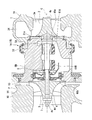
- FIG. 1 is a cross-sectional view of a turbocharger according to the first embodiment of the present invention.
- a turbocharger (rotary machine) 1 ⁇ / b> A includes a turbine wheel 2, a compressor wheel (impeller) 3, a rotating shaft (rotating body) 4, journal bearings 5 ⁇ / b> A and 5 ⁇ / b> B, and a bearing housing 6.
- the turbocharger 1A is mounted on an automobile or the like as an auxiliary machine for an engine, for example, in such a posture that the rotating shaft 4 extends in the horizontal direction.
- the alternate long and short dash line in FIG. 1 indicates the central axis C of the rotating shaft 4.
- a turbine wheel 2 provided in the turbine T is rotated about a central axis C by an exhaust gas flow supplied from an engine (not shown) to the turbine T.
- the rotating shaft 4 and the compressor wheel 3 rotate around the central axis C as the turbine wheel 2 rotates.
- the bearing housing 6 is supported on a vehicle body or the like via a bracket (not shown), a compressor P, a turbine T, and the like.
- the bearing housing 6 has bearing housing portions 61A and 61B for housing the journal bearings 5A and 5B therein.
- the bearing housing 6 has an opening 60a on one end side and an opening 60b on the other end side.
- the rotating shaft 4 is rotatably supported around the central axis C by journal bearings 5A and 5B housed in bearing housing portions 61A and 61B.
- the first end portion 4a and the second end portion 4b of the rotary shaft 4 protrude outside the bearing housing 6 through the openings 60a and 60b. That is, the rotation shaft 4 is housed in the bearing housing 6 in a part in the length direction along the central axis C.
- the turbine wheel 2 In the axial direction in which the central axis C extends, the turbine wheel 2 is provided on the first side (right side in FIG. 1) of the bearing housing 6, and the compressor wheel 3 is on the second side (in FIG. 1). , Left side). More specifically, the turbine wheel 2 is provided integrally with the first end portion 4 a of the rotating shaft 4, and the compressor wheel 3 is connected to the screw portion 4 n formed at the second end portion 4 b of the rotating shaft 4 with a nut 7. It is combined by screwing. The turbine wheel 2 and the compressor wheel 3 rotate around the central axis C together with the rotating shaft 4.
- the compressor P includes a compressor wheel 3 and a compressor casing (casing) 10.
- the compressor wheel 3 is a so-called impeller, and centrifugally compresses air when the rotating shaft 4 rotates. More specifically, air (intake air) flowing in from the second side in the direction in which the central axis C extends is increased in pressure and raised in temperature, and sent to the diffuser 13 formed on the radially outer side.
- FIG. 2 is a sectional view of the compressor in the first embodiment of the present invention.
- the compressor casing 10 forms a wheel inlet channel (inlet channel) 11, a wheel channel 12, a diffuser 13, and a scroll 14.
- the wheel inlet channel 11 is formed between an intake pipe (not shown) extending from an air cleaner box or the like and the wheel channel 12, for example.
- the wheel inlet flow passage 11 is disposed on the side closer to the compressor wheel 3 than the inclined portion 17 where the flow passage cross-sectional area gradually decreases as it approaches the compressor wheel 3, and the flow passage cross-sectional area does not change.
- a general part 18 is disposed on the side closer to the compressor wheel 3 than the inclined portion 17 where the flow passage cross-sectional area gradually decreases as it approaches the compressor wheel 3, and the flow passage cross-sectional area does not change.
- the wheel flow path 12 is a space that accommodates the compressor wheel 3.
- This wheel channel 12 forms a channel through which compressed air flows together with the compressor wheel 3. That is, the wheel flow path 12 can also be said to be a storage chamber that stores the compressor wheel 3.
- a slight gap is formed between the blade portion 19 of the compressor wheel 3 and the compressor casing 10. That is, the compressor casing 10 is formed with a curved surface 15 a that curves along the outer edge 19 g of the blade portion 19 at a position facing the blade portion 19.
- the wheel flow path 12 is gradually curved from the side close to the wheel inlet flow path 11 toward the turbine T side, and is curved so that the increase rate of the diameter increase gradually.
- the diffuser 13 extends from the outermost peripheral portion 12a of the wheel channel 12 toward the radially outer side with the central axis C as the center.
- the diffuser 13 converts, for example, the kinetic energy of air compressed by the compressor wheel 3 into pressure energy.
- the diffuser 13 connects the wheel inlet channel 11 and the scroll 14.
- the scroll 14 further converts the kinetic energy of the air flowing in from the diffuser 13 into pressure energy and discharges it to the outside of the compressor casing 10.
- the air discharged through the scroll 14 is supplied to an engine cylinder (not shown).
- the scroll 14 is formed in a circular shape in the cross section shown in FIG. 2, and is connected to the diffuser 13 at the end portion 14a closest to the turbine T.
- the scroll 14 is formed at a position overlapping the compressor wheel 3 in the direction in which the central axis C extends, and extends in the circumferential direction around the central axis C.
- the cross-sectional area of the scroll 14 formed in this manner gradually increases toward the discharge port (not shown) of the compressor P.
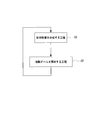
- FIG. 3 is a flowchart of the method for manufacturing the casing of the rotary machine in the first embodiment of the present invention.
- the compressor casing 10 is formed by a metal lamination method using a metal material such as an aluminum alloy. As shown in FIG. 3, the metal lamination method sequentially repeats step S1 in which material powder is spread to a predetermined thickness to form a material powder layer, and step S2 in which the material powder layer is irradiated with a melting beam.
- the material powder layer is formed by spreading material powder made of a metal material such as an aluminum alloy forming the compressor casing 10 to a predetermined thickness of, for example, 30 to 50 ⁇ m.
- step S2 of irradiating the melting beam the material powder layer is irradiated with a melting beam having energy for melting the material powder, such as a laser beam or an electron beam.
- the material powder is melted by the irradiation of the melting beam.
- the material powder is cooled and solidified to form a metal layer.
- the irradiation range of the melting beam with respect to the material powder layer is a range corresponding to the cross-sectional shape of the compressor casing 10.
- a metal layer forming a part of the compressor casing 10 is formed to a predetermined thickness.
- the step S1 of forming the material powder layer and the step S2 of irradiating the molten beam are sequentially repeated, and the irradiation range of the molten beam is sequentially changed in accordance with the cross-sectional shape of the compressor casing 10, whereby a plurality of metal layers are formed.
- the compressor casing 10 having a predetermined shape is formed by sequentially stacking.
- a high porosity portion 16 ⁇ / b> H is formed in a part of the compressor casing 10.
- the high porosity portion 16 ⁇ / b> H suppresses heat conduction from the wheel passage 12, the diffuser 13, and the scroll 14 to the wheel inlet passage 11.
- the high porosity portion 16H is formed, for example, continuously in the circumferential direction on the outer peripheral side of the general portion 18 of the wheel inlet passage 11.
- the high porosity portion 16H is not exposed to the inner peripheral surface 18f of the general portion 18, and is formed in a region on the outer peripheral side by a predetermined dimension from the inner peripheral surface 18f.
- the high porosity portion 16H is formed in the compressor casing 10 so as to have a higher porosity than the low porosity portion (main portion, remaining portion) 16L that forms a portion other than the high porosity portion 16H.
- the low-porosity portion 16L and the high-porosity portion 16H are the melt beam output, beam scanning speed, and beam scanning line width that are irradiated in the step of irradiating the melt beam when the compressor casing 10 is formed by the metal lamination method. It can be formed by adjusting etc.
- the output of the melting beam is set so that the material powder layer made of spread material powder is completely melted, the material powder is completely melted and then cooled and solidified, and the low porosity portion 16L having a porosity of less than 5% is obtained. Is formed.
- a high porosity portion 16H having a porosity of 5% or more is formed. Is done. For example, only the surface of the material powder may be melted and the inside of the high porosity portion 16H may be unmelted from the surface. In this way, the high porosity portion 16H maintains a shape of each material powder, and the surface melts so that a plurality of material powders are bonded to each other, and a large number of voids are formed between the material powders. It can be formed in a porous shape.
- the material powder may remain completely unmelted, that is, remain as the material powder.
- a portion where the surrounding low-porosity portion 16L is formed is irradiated with a melting beam, and a portion where the high-porosity portion 16H is formed is not irradiated with a melting beam. The powder is left unmelted.
- a molten metal material (molten metal) is not poured into a mold.
- a mold concave portion into which the molten metal is poured needs to be at least about 4 mm, for example.
- the metal lamination method it is only necessary to spread material powder and irradiate a melting beam, so that the thickness can be 4 mm or less. Therefore, as shown by a two-dot chain line in FIG. 2, for example, the outer peripheral wall 10F of the compressor casing 10 can be thinned.
- the outer peripheral wall 10F of the compressor casing 10 forming the scroll 14 it is possible to promote the heat radiation of the compressed air whose temperature is increased and increased by the rotation of the compressor wheel 3. Further, in the compressor casing 10, the metal temperature rises on the side close to the turbine T due to the influence of radiation. However, in the compressor casing 10, the heat dissipation effect can be promoted by reducing the thickness of the outer peripheral wall 10F facing the opposite side of the turbine T. In this way, the outer peripheral surface of the wheel channel 12 may be thinned at a plurality of locations spaced in the circumferential direction.
- the compressor casing 10 is provided with the low-porosity part 16L formed from the metal material, and the high-porosity part 16H.
- the high porosity portion 16H has a higher porosity than the low porosity portion 16L of the compressor casing 10, the thermal conductivity is lowered.
- the required rigidity can be maintained by the low porosity portion 16L while partially controlling the thermal conductivity of the compressor casing 10. As a result, it is possible to suppress heat transfer through the compressor casing 10 and improve the performance of the turbocharger 1A.
- the high porosity portion 16H can have a void. Thereby, the high porosity part 16H becomes low in thermal conductivity. Furthermore, the high porosity part 16H can be made to have the powder which consists of metal materials. Thereby, the high porosity portion 16H has a low density, a high porosity, and a low thermal conductivity. Such a high porosity portion 16H may be easily formed as long as the material powder is at least in an unmelted state upon irradiation with the melting beam.
- the high porosity portion 16H is formed between the scroll 14 and the wheel inlet passage 11 in the compressor casing 10 of the compressor P. Therefore, it is possible to suppress the heat of the air heated and raised by the compressor wheel 3 from the scroll 14 on the outlet side of the compressor P from being transmitted to the wheel inlet passage 11 side. As a result, an increase in suction temperature on the inlet side of the compressor P is suppressed, and a decrease in pressure ratio and efficiency in the compressor P can be suppressed.
- the compressor casing 10 by forming the compressor casing 10 by a metal lamination method, it is possible to reduce the thickness as compared with the case where the compressor casing 10 is formed by casting or die casting.
- the thickness of the compressor casing 10 it is possible to promote heat dissipation of the air heated by the compressor wheel 3.
- the surface metal temperature rises due to radiation on the turbine T side of the compressor casing 10, whereas the heat dissipation effect is promoted by reducing the thickness of the outer peripheral wall 10 ⁇ / b> F on the opposite side of the compressor casing 10 from the turbine T. it can.
- FIG. 4 is a cross-sectional view corresponding to FIG. 2 in a first modification of the first embodiment of the present invention.
- the high porosity portion 116H continuously forms the inclined portion 17 and the general portion 18 of the compressor casing 10 that forms the wheel inlet passage 11 and the wheel passage 12. May be.
- the high porosity portions 16H and 116H are continuously formed in the circumferential direction on the entire circumference, but the present invention is not limited to this configuration.
- the high porosity portions 16H and 116H may be provided at a plurality of locations at intervals in the circumferential direction.
- FIG. 1 is used, and the same parts as those in the first embodiment are denoted by the same reference numerals. Further, detailed description of the overall configuration of the turbocharger common to the configuration described in the first embodiment is omitted.
- a turbocharger (rotating machine) 1B includes a turbine wheel 2, a compressor wheel 3, a rotating shaft 4, journal bearings 5A and 5B, and a bearing housing 6.
- the turbine T includes a turbine casing (casing) 31 that houses the turbine wheel 2.
- the turbine casing 31 is attached to one end side of the bearing housing 6 via an attachment fitting 32.
- the turbine casing 31 has an opening 31 a at a position facing the bearing housing 6.
- a turbine wheel 2 having a plurality of turbine blades 2w in the circumferential direction is accommodated in the opening 31a.
- FIG. 5 is a cross-sectional view of the turbine in the second embodiment of the present invention.
- the turbine casing 31 includes a gas introduction part (not shown), a scroll flow path 34, and an exhaust part 35.
- the gas introduction part (not shown) sends a part of the exhaust gas discharged from the engine (not shown) into the turbine casing 31.
- the scroll flow path 34 is continuously formed in the circumferential direction so as to surround the outer peripheral side of the turbine wheel 2 continuously to the gas introduction part (not shown).
- the scroll flow path 34 is provided so as to face the outer peripheral portion of the turbine wheel 2 in at least a part of the circumferential direction, and forms a flow path through which exhaust gas for rotationally driving the turbine wheel 2 flows.
- Exhaust gas that has flowed from the gas introduction part 33 flows along the circumferential direction in the outer peripheral side of the turbine wheel 2 along the scroll flow path 34.
- the exhaust gas flowing along the circumferential direction hits the turbine blade 2w of the turbine wheel 2, whereby the turbine wheel 2 is rotationally driven.
- the exhaust gas strikes each turbine blade 2 w on the outer peripheral side of the turbine wheel 2, thereby changing the flow direction.
- the exhaust gas whose flow direction has been converted by the turbine blade 2 w is discharged from the inner peripheral side of the turbine wheel 2 into the exhaust part 35.
- the exhaust part 35 is formed in a cylindrical shape that continues in the direction away from the bearing housing 6 along the central axis C.
- the exhaust portion 35 has a tapered portion 35t whose inner diameter gradually increases as it is separated from the bearing housing 6, and a straight portion 35s provided downstream of the tapered portion 35t and having a constant inner diameter. is doing.
- the exhaust gas flows in the exhaust part 35 along the central axis C in a direction away from the bearing housing 6.
- a high porosity portion 36 ⁇ / b> H is formed in a part of the turbine casing 31.
- Such a high porosity portion 36H is formed continuously across, for example, the outer peripheral wall portion 34w of the scroll flow path 34, the tapered portion 35t of the exhaust portion 35, and the straight portion 35s.
- the high porosity portion 36 ⁇ / b> H is formed continuously in the circumferential direction of the turbine casing 31.
- the high porosity portion 36H is formed so as not to be exposed to the outer peripheral surface 31f and the inner peripheral surface 31g of the turbine casing 31.
- the high porosity portion 36 ⁇ / b> H suppresses heat conduction from the outer peripheral surface of the turbine casing 31 to the outside.
- the high porosity portion 36H is formed to have a higher porosity in the turbine casing 31 than the low porosity portion (main portion) 36L that forms a portion other than the high porosity portion 36H.
- the low porosity portion 36L and the high porosity portion 36H can be formed by the metal lamination method described above. When forming by this metal lamination method, the low-porosity portion 36L and the high-porosity portion 36H adjust the output of the molten beam to be irradiated, the beam scanning speed, the beam scanning line width, etc. Is formed.
- the high porosity portion 36H has a higher porosity than the low porosity portion 36L of the turbine casing 31, and therefore the thermal conductivity is low.
- the required rigidity can be maintained by the low porosity portion 36L while partially controlling the thermal conductivity of the turbine casing 31.
- heat transfer through the turbine casing 31 can be suppressed, and the performance of the turbocharger 1B can be improved.
- the high porosity portion 36 ⁇ / b> H can be formed on the outer peripheral portion of the turbine casing 31.
- the outer peripheral portion of the turbine casing 31 is, for example, a portion on the outer side (outer peripheral side) from the center in the thickness direction of the turbine casing 31.
- the exhaust gas having a higher temperature can be sent to the catalyst provided downstream of the exhaust unit 35. Since the catalyst has temperature dependence, the catalyst can function more efficiently by suppressing the temperature drop of the exhaust gas temperature.
- FIG. 6 is a cross-sectional view corresponding to FIG. 5 in a first modification of the second embodiment of the present invention.
- the high porosity portion 136H may be formed only on the outer peripheral wall portion 34w of the scroll flow path 34, for example. More specifically, the high porosity portion 136H may be formed only in the scroll flow path 34 without being formed in the exhaust portion 35 or the like in the turbine casing 31.
- the exhaust gas flowing through the scroll flow path 34 via the outer peripheral wall portion 34w of the scroll flow path 34 is formed.
- the release of heat can be suppressed.
- the temperature fall of the exhaust gas sent into the turbine wheel 2 can be suppressed, and the reduction of the output of the turbine T can be suppressed.
- FIG. 7 is a cross-sectional view corresponding to FIG. 5 in a second modification of the second embodiment of the present invention.
- the high porosity portion 236H may be provided only in the tapered portion 35t and the straight portion 35s of the exhaust portion 35, for example.
- the second modification it is possible to suppress the release of heat of the exhaust gas flowing through the exhaust part 35 via the exhaust part 35.
- exhaust gas having a higher temperature can be fed into the catalyst provided on the downstream side of the exhaust part 35.
- the catalyst can function more efficiently.
- the present invention is not limited to the above-described embodiment, and design changes can be made without departing from the spirit of the present invention.
- the high-porosity part 16H had the space
- the high porosity portion 16H may remove the powder from the voids. In this case, the powder can be removed by forming a hole for removing powder in the casing.
- the open type impeller has been described as an example.
- the impeller is not limited to the open type, and may be, for example, a closed type impeller provided integrally with a cover portion.
- turbochargers 1A and 1B have been described as examples of rotating machines.
- the rotating machine is not limited to a turbocharger, and may be a supercharger, a turbine engine, or the like, for example.
- the present invention can be applied to a rotating machine and a method for manufacturing a casing of the rotating machine. According to this invention, it is possible to suppress heat transfer through the casing and improve the performance of the rotating machine.
Abstract
Description
このような構成によれば、ケーシングの主部に対し、高気孔率部は気孔率が高いので、熱伝導性が低くなる。このような高気孔率部を部分的に設けることで、ケーシングの熱伝導性を部分的に制御しつつ、主部により必要な剛性を維持することができる。 According to the first aspect of the present invention, the rotating machine includes a rotating body that rotates around a central axis, and a casing that houses at least a part of the rotating body, and the casing is formed of a metal material. And a high porosity portion formed of the same material as the main portion and having a higher porosity than the main portion.
According to such a configuration, since the high porosity portion has a higher porosity than the main portion of the casing, the thermal conductivity is lowered. By providing such a high-porosity part partially, the required rigidity can be maintained by the main part while partially controlling the thermal conductivity of the casing.
このように、空隙を有することで、高気孔率部は熱伝導性が低くなる。このような空隙は、例えば、ケーシングを形成する金属材料からなる粉体を完全に溶融しないようにすることで形成することができる。 According to the second aspect of the present invention, in the rotary machine according to the first aspect, the high porosity portion may have a gap.
Thus, by having a space | gap, a high porosity part becomes low in heat conductivity. Such voids can be formed, for example, by preventing the powder made of a metal material forming the casing from being completely melted.
高気孔率部にケーシングを形成する金属材料からなる粉体が存在するようにすることで、高気孔率部の密度を低く、気孔率を高くすることができる。このような粉体は、例えば、ケーシングを形成する金属材料を完全に溶融しないことで、ケーシング中に粉体のまま存在させることができる。 According to the third aspect of the present invention, in the rotary machine according to the first aspect, the high porosity portion may include a powder made of the metal material.
By making the powder made of the metal material forming the casing exist in the high porosity portion, the density of the high porosity portion can be lowered and the porosity can be increased. Such a powder can exist as a powder in the casing, for example, by not completely melting the metal material forming the casing.
このように、ケーシングの全周ではなく、周方向に間隔を空けて部分的に高気孔率部を設けると、高気孔率部によって熱伝導性を抑制することができる。高気孔率部以外は、高気孔率部よりも気孔率が低い主部によって形成されることなり、ケーシングのカバーの強度を確保することができる。 According to a fourth aspect of the present invention, in the rotary machine according to the first aspect, the high porosity portion is provided at a plurality of locations spaced in the circumferential direction of the central axis. May be.
As described above, when the high porosity portion is partially provided at intervals in the circumferential direction instead of the entire circumference of the casing, the thermal conductivity can be suppressed by the high porosity portion. Except for the high porosity portion, the main portion is formed with a lower porosity than the high porosity portion, and the strength of the casing cover can be ensured.
これにより、コンプレッサの出口側のスクロール流路から、インペラによって昇温、昇圧される空気の熱が、入口流路側に伝わることを抑制できる。この結果、コンプレッサの入口側における吸込温度上昇が抑制され、コンプレッサの圧力比低下、効率低下を抑制することができる。 According to a fifth aspect of the present invention, the rotary machine is the rotary machine according to the first aspect, wherein the rotary machine is a turbocharger, the casing is a compressor casing of the turbocharger, and the high porosity portion. May be formed between a scroll channel and an inlet channel formed in the compressor casing.
Thereby, it can suppress that the heat of the air heated up and pressure | voltage-risen by the impeller from the scroll flow path by the side of a compressor is transmitted to the inlet flow path side. As a result, an increase in suction temperature on the inlet side of the compressor is suppressed, and a decrease in pressure ratio and efficiency in the compressor can be suppressed.
これにより、高気孔率部により、タービンケーシング内を通る排ガスの熱がタービンケーシングを通して放出されることを抑制できる。さらに、タービンケーシングの外周部側のみ気孔率を高めることで、高温ガスに晒されるタービンケーシングの内面の耐酸化性を維持することができる。 According to a sixth aspect of the present invention, the rotary machine is the rotary machine according to the first aspect, wherein the rotary machine is a turbocharger, the casing is a turbine casing of the turbocharger, and the high porosity portion. Is formed on the outer periphery of the turbine casing.
Thereby, it can suppress that the heat | fever of the waste gas which passes the inside of a turbine casing is discharge | released through a turbine casing by a high-porosity part. Furthermore, the oxidation resistance of the inner surface of the turbine casing exposed to the high-temperature gas can be maintained by increasing the porosity only on the outer peripheral side of the turbine casing.
このようにして、金属材料から形成された主部と、主部よりも気孔率が高い高気孔率部と、を備えるケーシングを形成することができる。このようなケーシングは、高気孔率部の気孔率が高いので、熱伝導率が部分的に低くなる。このような高気孔率部を設けることで、ケーシングの熱伝導率を部分的に制御しつつ、主部により必要な剛性を維持することができる。 According to a seventh aspect of the present invention, there is provided a method of manufacturing a casing of a rotary machine, the method of manufacturing the casing of the rotary machine as described above, wherein the material powder made of a metal material forming the casing is spread over the material. The step of forming the casing by repeating the step of forming a powder layer and the step of melting the material powder by irradiating a melting beam includes the step of forming the casing and melting the material powder by the output of the melting beam, beam scanning By adjusting at least one of the speed and the beam scanning line width, a high porosity portion having a higher porosity than the remaining portion of the casing is formed in a part of the casing.
In this manner, a casing including a main portion made of a metal material and a high porosity portion having a higher porosity than the main portion can be formed. Since such a casing has a high porosity in the high porosity portion, the thermal conductivity is partially lowered. By providing such a high porosity portion, it is possible to maintain necessary rigidity by the main portion while partially controlling the thermal conductivity of the casing.
次に、この発明の第一実施形態における回転機械、回転機械のケーシングの製造方法を図面に基づき説明する。
図1は、この発明の第一実施形態におけるターボチャージャの断面図である。
図1に示すように、ターボチャージャ(回転機械)1Aは、タービンホイール2、コンプレッサホイール(インペラ)3、回転軸(回転体)4、ジャーナルベアリング5A,5B、及び軸受ハウジング6を備えている。このターボチャージャ1Aは、例えば、回転軸4が水平方向に延在するような姿勢で自動車等にエンジンの補機として搭載される。ここで、図1に示す一点鎖線は、回転軸4の中心軸Cを示している。 (First embodiment)
Next, a rotating machine and a method for manufacturing a casing of the rotating machine according to the first embodiment of the present invention will be described with reference to the drawings.
FIG. 1 is a cross-sectional view of a turbocharger according to the first embodiment of the present invention.
As shown in FIG. 1, a turbocharger (rotary machine) 1 </ b> A includes a
回転軸4及びコンプレッサホイール3は、タービンホイール2の回転に伴って中心軸Cを中心に回転する。 In the turbocharger 1 </ b> A, a
The rotating
コンプレッサホイール3は、いわゆるインペラであって、回転軸4が回転することによって空気を遠心圧縮する。より具体的には、中心軸Cの延びる方向で第二側から流入する空気(吸気)を昇圧および昇温して、その径方向外側に形成されるディフューザ13へと送り出す。 The compressor P includes a
The
図2に示すように、コンプレッサケーシング10は、ホイール入口流路(入口流路)11と、ホイール流路12と、ディフューザ13と、スクロール14と、を形成する。 FIG. 2 is a sectional view of the compressor in the first embodiment of the present invention.
As shown in FIG. 2, the
コンプレッサケーシング10は、例えばアルミ合金等の金属材料を用い、金属積層法により形成される。
図3に示すように、金属積層法は、材料粉を所定厚さに敷き詰めて材料粉層を形成する工程S1と、材料粉層に溶融ビームを照射する工程S2と、を順次繰り返す。 FIG. 3 is a flowchart of the method for manufacturing the casing of the rotary machine in the first embodiment of the present invention.
The
As shown in FIG. 3, the metal lamination method sequentially repeats step S1 in which material powder is spread to a predetermined thickness to form a material powder layer, and step S2 in which the material powder layer is irradiated with a melting beam.
高気孔率部16Hは、ホイール流路12、ディフューザ13、および、スクロール14からホイール入口流路11への熱伝導を抑制する。高気孔率部16Hは、例えば、ホイール入口流路11の一般部18の外周側に、周方向に連続して形成されている。高気孔率部16Hは、一般部18の内周面18fに露出せず、内周面18fよりも所定の寸法だけ外周側の領域に形成されている。
この高気孔率部16Hは、コンプレッサケーシング10において、高気孔率部16H以外の部分を形成する低気孔率部(主部、残部)16Lよりも、気孔率が高くなるように形成されている。 As shown in FIG. 2, a high porosity portion 16 </ b> H is formed in a part of the
The high porosity portion 16 </ b> H suppresses heat conduction from the
The
この高気孔率部16Hは、例えば材料粉の表面のみが溶融し、表面よりも内側が未溶融の状態であってもよい。このようにすると、高気孔率部16Hは、各材料粉の形状を維持したまま、表面が溶融することで複数の材料粉同士が結着しつつ、材料粉間に多数の空隙が形成された多孔質状に形成することができる。
ここで、上述した高気孔率部16Hは、材料粉が完全に未溶融のまま、すなわち材料粉のまま残存していてもよい。これには、例えば、周囲の低気孔率部16Lを形成する部分に対しては、溶融ビームを照射し、高気孔率部16Hを形成する部分に対しては、溶融ビームを非照射とし、材料粉を未溶融のまま残存させる。 For example, if the melting beam output is set to be weak so that the spread material powder does not completely melt and remains partially unmelted, for example, a
For example, only the surface of the material powder may be melted and the inside of the
Here, in the
そこで、図2中に二点鎖線で示すように、例えばコンプレッサケーシング10の外周壁10Fを薄肉化することができる。
このように、スクロール14を形成するコンプレッサケーシング10の外周壁10Fを薄肉化することで、コンプレッサホイール3の回転により昇温、昇圧された圧縮空気の放熱を促進することができる。さらに、コンプレッサケーシング10は、タービンTに近い側が、輻射の影響でメタルの温度が上昇する。しかし、コンプレッサケーシング10において、タービンTとは反対側を向く外周壁10Fが薄肉化されることで、放熱効果を促進できる。
なお、このように、ホイール流路12の外周面を薄肉化するのは、周方向に間隔を空けた複数個所であってもよい。 In such a metal laminating method, unlike a casting or die casting method, a molten metal material (molten metal) is not poured into a mold. In the case of a mold, in order to ensure the flowability of the molten metal, a mold concave portion into which the molten metal is poured needs to be at least about 4 mm, for example. On the other hand, in the metal lamination method, it is only necessary to spread material powder and irradiate a melting beam, so that the thickness can be 4 mm or less.
Therefore, as shown by a two-dot chain line in FIG. 2, for example, the outer
In this way, by thinning the outer
In this way, the outer peripheral surface of the
その結果、コンプレッサケーシング10を介しての熱伝達を抑え、ターボチャージャ1Aの性能を向上することが可能となる。 Therefore, according to 1st embodiment mentioned above, the
As a result, it is possible to suppress heat transfer through the
さらに、高気孔率部16Hは、金属材料からなる粉体が存在しているようにすることができる。これにより、高気孔率部16Hは密度が低く、気孔率が高くなり、熱伝導性が低くなる。
これらのような高気孔率部16Hは、溶融ビームの照射の際に、材料粉の少なくとも未溶融の状態とすればよく、容易に形成できる。 Furthermore, according to the first embodiment, the
Furthermore, the
Such a
このように、コンプレッサケーシング10の薄肉化を図ることで、コンプレッサホイール3により昇温した空気の放熱を促進することができる。
さらに、コンプレッサケーシング10のタービンT側が輻射の影響で表面メタル温度が上昇するのに対し、コンプレッサケーシング10のタービンTとは反対側の外周壁10Fの肉厚を薄くすることで、放熱効果を促進できる。 Furthermore, by forming the
Thus, by reducing the thickness of the
Further, the surface metal temperature rises due to radiation on the turbine T side of the
第一実施形態では、高気孔率部16Hを、ホイール入口流路11の一般部18の外周側に形成したが、これに限るものではない。
図4は、この発明の第一実施形態の第一変形例における図2に相当する断面図である。
例えば、図4に示すように、高気孔率部116Hは、ホイール入口流路11を形成するコンプレッサケーシング10の傾斜部17および一般部18と、ホイール流路12とを連続して形成するようにしてもよい。 (First modification of the first embodiment)
In the first embodiment, the
FIG. 4 is a cross-sectional view corresponding to FIG. 2 in a first modification of the first embodiment of the present invention.
For example, as shown in FIG. 4, the high porosity portion 116H continuously forms the
第一実施形態においては、図2、図4に示すように、高気孔率部16H,116Hを周方向に連続して全周に形成したが、この構成に限られない。例えば、高気孔率部16H,116Hは、周方向に間隔を空けて複数個所に設けるようにしてもよい。 (Second modification of the first embodiment)
In the first embodiment, as shown in FIGS. 2 and 4, the
次に、この発明の第二実施形態を図面に基づき説明する。この第二実施形態の説明においては、図1を援用するとともに、第一実施形態と同一部分に同一符号を付して説明する。さらに、第一実施形態で説明した構成と共通するターボチャージャの全体構成については、その詳細説明を省略する。 (Second embodiment)
Next, a second embodiment of the present invention will be described with reference to the drawings. In the description of the second embodiment, FIG. 1 is used, and the same parts as those in the first embodiment are denoted by the same reference numerals. Further, detailed description of the overall configuration of the turbocharger common to the configuration described in the first embodiment is omitted.
図5に示すように、タービンケーシング31は、ガス導入部(図示無し)と、スクロール流路34と、排気部35と、を備えている。 FIG. 5 is a cross-sectional view of the turbine in the second embodiment of the present invention.
As shown in FIG. 5, the
低気孔率部36Lと高気孔率部36Hとは、上述した金属積層法で形成できる。この金属積層法で形成する際、低気孔率部36Lと高気孔率部36Hとは、溶融ビームを照射する工程で、照射する溶融ビームの出力、ビーム走査速度、ビーム走査線幅等を調整することで形成される。 The high porosity portion 36 </ b> H suppresses heat conduction from the outer peripheral surface of the
The
その結果、タービンケーシング31を介した熱伝達を抑え、ターボチャージャ1Bの性能を向上することが可能となる。 In the rotating machine and the method for manufacturing the casing of the rotating machine of this embodiment, the
As a result, heat transfer through the
上述した第二実施形態においては、高気孔率部36Hを、例えば、スクロール流路34の外周壁部34w、排気部35のテーパ部35t、ストレート部35sにわたって連続して形成する場合について説明したが、この構成に限られない。
図6は、この発明の第二実施形態の第一変形例における図5に相当する断面図である。
図6に示すように、高気孔率部136Hは、例えば、スクロール流路34の外周壁部34wのみに形成するようにしてもよい。より具体的には、高気孔率部136Hは、タービンケーシング31のうち、排気部35などには形成せずに、スクロール流路34にのみ形成するようにしてもよい。 (First modification of the second embodiment)
In the second embodiment described above, a case has been described in which the
FIG. 6 is a cross-sectional view corresponding to FIG. 5 in a first modification of the second embodiment of the present invention.
As shown in FIG. 6, the
図7は、この発明の第二実施形態の第二変形例における図5に相当する断面図である。
図7に示すように、高気孔率部236Hは、例えば、排気部35のテーパ部35t、ストレート部35sのみに設けるようにしてもよい。 (Second modification of the second embodiment)
FIG. 7 is a cross-sectional view corresponding to FIG. 5 in a second modification of the second embodiment of the present invention.
As shown in FIG. 7, the
図5から図7では、高気孔率部36H,136H,236Hを周方向に連続して全周に形成する場合を例示した。しかし、この構成に限られず、例えば、高気孔率部36H,136H,236Hは、周方向に間隔を空けて複数個所に設けるようにしてもよい。 (Second modification of the second embodiment)
5 to 7 exemplify the case where the
この発明は、上述した実施形態に限定されるものではなく、この発明の趣旨を逸脱しない範囲において、設計変更可能である。
上述した第一実施形態においては、高気孔率部16Hが、金属材料からなる粉体が未溶融の状態で存在している空隙を有する場合について説明した。しかし、高気孔率部16Hは、空隙から粉体を除去しても良い。この場合、ケーシングに粉体除去用の孔などを形成すれば紛体を除去することができる。 (Other embodiments)
The present invention is not limited to the above-described embodiment, and design changes can be made without departing from the spirit of the present invention.
In 1st embodiment mentioned above, the case where the high-
2 タービンホイール
2w タービン翼
3 コンプレッサホイール
4 回転軸(回転体)
4a 第一端部
4b 第二端部
4n ネジ部
5A,5B ジャーナルベアリング
6 軸受ハウジング
7 ナット
10 コンプレッサケーシング(ケーシング)
10F 外周壁
11 ホイール入口流路(入口流路)
12 ホイール流路
12a 最外周部
13 ディフューザ
14 スクロール
14a 端部
15a 曲面
16H,36H,116H,136H,236H 高気孔率部
16L,36L 低気孔率部(主部、残部)
17 傾斜部
18 一般部
18f 内周面
19 ブレード部
19g 外縁
31 タービンケーシング(ケーシング)
31a 開口部
31f 外周面
31g 内周面
32 取付金具
34 スクロール流路
34w 外周壁部
35 排気部
35s ストレート部
35t テーパ部
60a,60b 開口部
61A,61B ベアリング収容部
C 中心軸
P コンプレッサ
T タービン 1A, 1B Turbocharger (Rotating machine)
2
4a
10F Outer
12
17
31a Opening 31f Outer peripheral surface 31g Inner
Claims (7)
- 中心軸回りに回転する回転体と、
前記回転体の少なくとも一部を収容するケーシングと、を備え、
前記ケーシングは、金属材料から形成された主部と、前記主部と同材料で形成され、かつ前記主部よりも気孔率が高い高気孔率部と、を備える回転機械。 A rotating body that rotates about a central axis;
A casing for accommodating at least a part of the rotating body,
The casing includes a main part formed of a metal material, and a high-porosity part formed of the same material as the main part and having a higher porosity than the main part. - 前記高気孔率部は、空隙を有する請求項1に記載の回転機械。 The rotary machine according to claim 1, wherein the high porosity portion has a gap.
- 前記高気孔率部は、前記金属材料からなる粉体が存在している請求項1に記載の回転機械。 The rotating machine according to claim 1, wherein the high porosity portion includes a powder made of the metal material.
- 前記高気孔率部は、前記中心軸の周方向に間隔を空けた複数個所に設けられている、請求項1に記載の回転機械。 The rotary machine according to claim 1, wherein the high porosity portion is provided at a plurality of locations spaced in the circumferential direction of the central axis.
- 前記回転機械はターボチャージャであり、
前記ケーシングは、前記ターボチャージャのコンプレッサケーシングであり、
前記高気孔率部は、前記コンプレッサケーシングに形成されたスクロール流路と入口流路との間に形成されている請求項1に記載の回転機械。 The rotating machine is a turbocharger;
The casing is a compressor casing of the turbocharger;
The rotary machine according to claim 1, wherein the high porosity portion is formed between a scroll flow path and an inlet flow path formed in the compressor casing. - 前記回転機械はターボチャージャであり、
前記ケーシングは、前記ターボチャージャのタービンケーシングであり、
前記高気孔率部は、前記タービンケーシングの外周部に形成されている請求項1に記載の回転機械。 The rotating machine is a turbocharger;
The casing is a turbine casing of the turbocharger;
The rotating machine according to claim 1, wherein the high porosity portion is formed on an outer peripheral portion of the turbine casing. - 請求項1から6の何れか一項に記載の回転機械の前記ケーシングの製造方法であって、
前記ケーシングを形成する金属材料からなる材料粉を敷き詰めて材料粉層を形成する工程と、溶融ビームを照射して前記材料粉を溶融させる工程と、を繰り返すことで前記ケーシングを形成し、
前記材料粉を溶融させる工程は、前記溶融ビームの出力、ビーム走査速度、及びビーム走査線幅の少なくとも一つを調整することで、前記ケーシングの一部に、前記ケーシングの残部よりも気孔率が高い高気孔率部を形成する、回転機械のケーシングの製造方法。 A method for manufacturing the casing of the rotating machine according to any one of claims 1 to 6,
Forming the casing by repeating the process of forming a material powder layer by spreading material powder made of a metal material that forms the casing, and the step of melting the material powder by irradiating a melting beam,
In the step of melting the material powder, by adjusting at least one of the output of the melting beam, the beam scanning speed, and the beam scanning line width, the porosity of a part of the casing is larger than the remainder of the casing. A method of manufacturing a casing for a rotary machine, which forms a high porosity portion.
Priority Applications (5)
| Application Number | Priority Date | Filing Date | Title |
|---|---|---|---|
| JP2018505204A JP6640326B2 (en) | 2016-03-18 | 2016-03-18 | Method of manufacturing rotary machine, casing of rotary machine |
| CN201680083527.2A CN108779709A (en) | 2016-03-18 | 2016-03-18 | Rotating machinery, rotating machinery shell manufacturing method |
| US16/082,866 US10634042B2 (en) | 2016-03-18 | 2016-03-18 | Rotating machine and method for manufacturing casing for rotating machine |
| PCT/JP2016/058804 WO2017158837A1 (en) | 2016-03-18 | 2016-03-18 | Rotating machine and method for manufacturing casing for rotating machine |
| EP16894455.1A EP3412890B1 (en) | 2016-03-18 | 2016-03-18 | Rotating machine and method for manufacturing casing for rotating machine |
Applications Claiming Priority (1)
| Application Number | Priority Date | Filing Date | Title |
|---|---|---|---|
| PCT/JP2016/058804 WO2017158837A1 (en) | 2016-03-18 | 2016-03-18 | Rotating machine and method for manufacturing casing for rotating machine |
Publications (1)
| Publication Number | Publication Date |
|---|---|
| WO2017158837A1 true WO2017158837A1 (en) | 2017-09-21 |
Family
ID=59850215
Family Applications (1)
| Application Number | Title | Priority Date | Filing Date |
|---|---|---|---|
| PCT/JP2016/058804 WO2017158837A1 (en) | 2016-03-18 | 2016-03-18 | Rotating machine and method for manufacturing casing for rotating machine |
Country Status (5)
| Country | Link |
|---|---|
| US (1) | US10634042B2 (en) |
| EP (1) | EP3412890B1 (en) |
| JP (1) | JP6640326B2 (en) |
| CN (1) | CN108779709A (en) |
| WO (1) | WO2017158837A1 (en) |
Cited By (1)
| Publication number | Priority date | Publication date | Assignee | Title |
|---|---|---|---|---|
| JP2019100205A (en) * | 2017-11-29 | 2019-06-24 | 三菱重工業株式会社 | Turbine wheel, turbocharger and manufacturing method of turbine wheel |
Families Citing this family (2)
| Publication number | Priority date | Publication date | Assignee | Title |
|---|---|---|---|---|
| DE102016207745A1 (en) * | 2016-05-04 | 2017-11-09 | Continental Automotive Gmbh | Turbine housing for a turbocharger of an internal combustion engine and turbocharger |
| DE102020101904A1 (en) * | 2020-01-27 | 2021-07-29 | Röchling Automotive SE & Co. KG | Method for producing an air duct component with an additive production method while changing at least one process parameter during the execution of the method and such an air duct component |
Citations (7)
| Publication number | Priority date | Publication date | Assignee | Title |
|---|---|---|---|---|
| JPS59118801A (en) * | 1982-12-27 | 1984-07-09 | Toshiba Corp | Production of sintered parts |
| JP2003129862A (en) * | 2001-10-23 | 2003-05-08 | Toshiba Corp | Turbine blade production method |
| JP2005219384A (en) * | 2004-02-06 | 2005-08-18 | Toyota Motor Corp | Injection molding mould |
| JP2013129899A (en) * | 2011-12-22 | 2013-07-04 | Toyota Motor Corp | Method for manufacturing heat insulating member, and internal combustion engine manufactured therewith |
| JP2014122582A (en) * | 2012-12-21 | 2014-07-03 | Toyota Motor Corp | Supercharger |
| JP2015187411A (en) * | 2014-03-26 | 2015-10-29 | 株式会社東芝 | Rotor blade integrated type turbine rotor, steam turbine, and method for manufacturing rotor blade integrated type turbine rotor |
| JP2016023351A (en) * | 2014-07-23 | 2016-02-08 | 株式会社日立製作所 | Alloy structure |
Family Cites Families (14)
| Publication number | Priority date | Publication date | Assignee | Title |
|---|---|---|---|---|
| JPS55149178A (en) * | 1979-05-02 | 1980-11-20 | Ishikawajima Harima Heavy Ind | Composite heat resisting structure of ceramic and metal and its manufacture |
| US5980203A (en) * | 1996-06-05 | 1999-11-09 | Atlas Compco Comptec | Spark-prevention coating for oxygen compressor shroud |
| US5704759A (en) * | 1996-10-21 | 1998-01-06 | Alliedsignal Inc. | Abrasive tip/abradable shroud system and method for gas turbine compressor clearance control |
| JP2001234753A (en) | 2000-02-24 | 2001-08-31 | Hitachi Ltd | Compressor housing for supercharger |
| JP2007154750A (en) * | 2005-12-05 | 2007-06-21 | Ishikawajima Harima Heavy Ind Co Ltd | Oxygen compressor |
| JP4655277B2 (en) * | 2006-01-23 | 2011-03-23 | トヨタ自動車株式会社 | Structure |
| ITMI20070665A1 (en) * | 2007-03-30 | 2008-09-30 | Nuovo Pignone Spa | ABRADIBLE AND ANTI-ROUND COATING FOR ROTARY MACHINES IN LUIDO |
| CN201133281Y (en) * | 2007-12-25 | 2008-10-15 | 孙宇 | Turbo-charger |
| JP5665602B2 (en) * | 2011-02-25 | 2015-02-04 | 三菱重工業株式会社 | Multistage turbocharger structure |
| ITFI20120035A1 (en) * | 2012-02-23 | 2013-08-24 | Nuovo Pignone Srl | "IMPELLER PRODUCTION FOR TURBO-MACHINES" |
| WO2015112422A1 (en) * | 2014-01-22 | 2015-07-30 | United Technologies Corporation | Additive manufacturing system and method of operation |
| US10167727B2 (en) * | 2014-08-13 | 2019-01-01 | United Technologies Corporation | Gas turbine engine blade containment system |
| US11359632B2 (en) * | 2014-10-31 | 2022-06-14 | Ingersoll-Rand Industrial U.S., Inc. | Rotary screw compressor rotor having work extraction mechanism |
| US10132185B2 (en) * | 2014-11-07 | 2018-11-20 | Rolls-Royce Corporation | Additive process for an abradable blade track used in a gas turbine engine |
-
2016
- 2016-03-18 WO PCT/JP2016/058804 patent/WO2017158837A1/en active Application Filing
- 2016-03-18 US US16/082,866 patent/US10634042B2/en active Active
- 2016-03-18 CN CN201680083527.2A patent/CN108779709A/en active Pending
- 2016-03-18 JP JP2018505204A patent/JP6640326B2/en not_active Expired - Fee Related
- 2016-03-18 EP EP16894455.1A patent/EP3412890B1/en active Active
Patent Citations (7)
| Publication number | Priority date | Publication date | Assignee | Title |
|---|---|---|---|---|
| JPS59118801A (en) * | 1982-12-27 | 1984-07-09 | Toshiba Corp | Production of sintered parts |
| JP2003129862A (en) * | 2001-10-23 | 2003-05-08 | Toshiba Corp | Turbine blade production method |
| JP2005219384A (en) * | 2004-02-06 | 2005-08-18 | Toyota Motor Corp | Injection molding mould |
| JP2013129899A (en) * | 2011-12-22 | 2013-07-04 | Toyota Motor Corp | Method for manufacturing heat insulating member, and internal combustion engine manufactured therewith |
| JP2014122582A (en) * | 2012-12-21 | 2014-07-03 | Toyota Motor Corp | Supercharger |
| JP2015187411A (en) * | 2014-03-26 | 2015-10-29 | 株式会社東芝 | Rotor blade integrated type turbine rotor, steam turbine, and method for manufacturing rotor blade integrated type turbine rotor |
| JP2016023351A (en) * | 2014-07-23 | 2016-02-08 | 株式会社日立製作所 | Alloy structure |
Non-Patent Citations (1)
| Title |
|---|
| See also references of EP3412890A4 * |
Cited By (2)
| Publication number | Priority date | Publication date | Assignee | Title |
|---|---|---|---|---|
| JP2019100205A (en) * | 2017-11-29 | 2019-06-24 | 三菱重工業株式会社 | Turbine wheel, turbocharger and manufacturing method of turbine wheel |
| JP7002306B2 (en) | 2017-11-29 | 2022-01-20 | 三菱重工業株式会社 | How to manufacture turbine wheels, turbochargers and turbine wheels |
Also Published As
| Publication number | Publication date |
|---|---|
| EP3412890A1 (en) | 2018-12-12 |
| EP3412890A4 (en) | 2019-03-13 |
| EP3412890B1 (en) | 2021-05-05 |
| JP6640326B2 (en) | 2020-02-05 |
| US10634042B2 (en) | 2020-04-28 |
| US20190093550A1 (en) | 2019-03-28 |
| JPWO2017158837A1 (en) | 2019-01-10 |
| CN108779709A (en) | 2018-11-09 |
Similar Documents
| Publication | Publication Date | Title |
|---|---|---|
| JP4697492B2 (en) | Electric turbocharger | |
| US10662806B2 (en) | Compressor, turbine and turbocharger | |
| JP6671858B2 (en) | Electric motor driven compressor with bidirectional coolant passage | |
| JP5933552B2 (en) | Exhaust turbocharger | |
| WO2017158837A1 (en) | Rotating machine and method for manufacturing casing for rotating machine | |
| EP2617961B1 (en) | Radial turbine | |
| CN110036553A (en) | Motor | |
| JP2009544882A (en) | Turbine housing for turbocharger | |
| WO2015005343A1 (en) | Turbo compressor and turbo refrigerating machine | |
| JP2015518115A (en) | Exhaust gas turbocharger | |
| JPWO2017168629A1 (en) | Turbocharger | |
| KR20150138272A (en) | Turbine wheel of an exhaust-gas turbocharger | |
| WO2016088690A1 (en) | Compressor, supercharger equipped with same and method of adjusting throat passage width of compressor | |
| JP7012350B2 (en) | Rotating disk device for centrifugal atomizer, centrifugal atomizer, and method for manufacturing metal powder | |
| JP6388772B2 (en) | Centrifugal compressor and diffuser manufacturing method | |
| JP5797724B2 (en) | Exhaust gas turbocharger | |
| JP2008196327A (en) | Turbocharger | |
| US20170081970A1 (en) | Cast turbocharger turbine housing having guide vanes | |
| JP2014050133A (en) | Rotor, electric motor, and supercharger | |
| JP7130675B2 (en) | Turbine rotor blade, turbocharger, and turbine rotor blade manufacturing method | |
| JP7002306B2 (en) | How to manufacture turbine wheels, turbochargers and turbine wheels | |
| JP2004143937A (en) | Housing for supercharger and its manufacturing method | |
| JP2015224601A (en) | Electric supercharger | |
| JP2015224600A (en) | Electric supercharger | |
| EP3764525B1 (en) | Electric motor and housing with integrated heat exchanger channels |
Legal Events
| Date | Code | Title | Description |
|---|---|---|---|
| WWE | Wipo information: entry into national phase |
Ref document number: 2018505204 Country of ref document: JP |
|
| WWE | Wipo information: entry into national phase |
Ref document number: 2016894455 Country of ref document: EP |
|
| NENP | Non-entry into the national phase |
Ref country code: DE |
|
| ENP | Entry into the national phase |
Ref document number: 2016894455 Country of ref document: EP Effective date: 20180907 |
|
| 121 | Ep: the epo has been informed by wipo that ep was designated in this application |
Ref document number: 16894455 Country of ref document: EP Kind code of ref document: A1 |