EP3412890A1 - Rotating machine and method for manufacturing casing for rotating machine - Google Patents
Rotating machine and method for manufacturing casing for rotating machine Download PDFInfo
- Publication number
- EP3412890A1 EP3412890A1 EP16894455.1A EP16894455A EP3412890A1 EP 3412890 A1 EP3412890 A1 EP 3412890A1 EP 16894455 A EP16894455 A EP 16894455A EP 3412890 A1 EP3412890 A1 EP 3412890A1
- Authority
- EP
- European Patent Office
- Prior art keywords
- section
- casing
- porosity
- rotating machine
- turbine
- Prior art date
- Legal status (The legal status is an assumption and is not a legal conclusion. Google has not performed a legal analysis and makes no representation as to the accuracy of the status listed.)
- Granted
Links
- 238000000034 method Methods 0.000 title claims description 18
- 238000004519 manufacturing process Methods 0.000 title claims description 11
- 239000000463 material Substances 0.000 claims abstract description 43
- 239000007769 metal material Substances 0.000 claims abstract description 17
- 239000000843 powder Substances 0.000 claims description 50
- 238000002844 melting Methods 0.000 claims description 28
- 230000008018 melting Effects 0.000 claims description 28
- 229910052751 metal Inorganic materials 0.000 claims description 19
- 239000002184 metal Substances 0.000 claims description 19
- 230000001678 irradiating effect Effects 0.000 claims description 8
- 238000003892 spreading Methods 0.000 claims description 4
- 238000003475 lamination Methods 0.000 description 9
- 230000007423 decrease Effects 0.000 description 8
- 239000003054 catalyst Substances 0.000 description 5
- 229910000838 Al alloy Inorganic materials 0.000 description 4
- 230000005855 radiation Effects 0.000 description 4
- 238000005266 casting Methods 0.000 description 3
- 238000004512 die casting Methods 0.000 description 3
- 230000003647 oxidation Effects 0.000 description 2
- 238000007254 oxidation reaction Methods 0.000 description 2
- 230000000191 radiation effect Effects 0.000 description 2
- 238000009751 slip forming Methods 0.000 description 2
- 230000006835 compression Effects 0.000 description 1
- 238000007906 compression Methods 0.000 description 1
- 230000003247 decreasing effect Effects 0.000 description 1
- 230000000694 effects Effects 0.000 description 1
- 238000010894 electron beam technology Methods 0.000 description 1
- 239000000155 melt Substances 0.000 description 1
Images


Classifications
-
- F—MECHANICAL ENGINEERING; LIGHTING; HEATING; WEAPONS; BLASTING
- F02—COMBUSTION ENGINES; HOT-GAS OR COMBUSTION-PRODUCT ENGINE PLANTS
- F02B—INTERNAL-COMBUSTION PISTON ENGINES; COMBUSTION ENGINES IN GENERAL
- F02B39/00—Component parts, details, or accessories relating to, driven charging or scavenging pumps, not provided for in groups F02B33/00 - F02B37/00
-
- B—PERFORMING OPERATIONS; TRANSPORTING
- B22—CASTING; POWDER METALLURGY
- B22F—WORKING METALLIC POWDER; MANUFACTURE OF ARTICLES FROM METALLIC POWDER; MAKING METALLIC POWDER; APPARATUS OR DEVICES SPECIALLY ADAPTED FOR METALLIC POWDER
- B22F10/00—Additive manufacturing of workpieces or articles from metallic powder
- B22F10/20—Direct sintering or melting
- B22F10/28—Powder bed fusion, e.g. selective laser melting [SLM] or electron beam melting [EBM]
-
- B—PERFORMING OPERATIONS; TRANSPORTING
- B22—CASTING; POWDER METALLURGY
- B22F—WORKING METALLIC POWDER; MANUFACTURE OF ARTICLES FROM METALLIC POWDER; MAKING METALLIC POWDER; APPARATUS OR DEVICES SPECIALLY ADAPTED FOR METALLIC POWDER
- B22F10/00—Additive manufacturing of workpieces or articles from metallic powder
- B22F10/30—Process control
- B22F10/38—Process control to achieve specific product aspects, e.g. surface smoothness, density, porosity or hollow structures
-
- B—PERFORMING OPERATIONS; TRANSPORTING
- B23—MACHINE TOOLS; METAL-WORKING NOT OTHERWISE PROVIDED FOR
- B23K—SOLDERING OR UNSOLDERING; WELDING; CLADDING OR PLATING BY SOLDERING OR WELDING; CUTTING BY APPLYING HEAT LOCALLY, e.g. FLAME CUTTING; WORKING BY LASER BEAM
- B23K26/00—Working by laser beam, e.g. welding, cutting or boring
- B23K26/34—Laser welding for purposes other than joining
- B23K26/342—Build-up welding
-
- B—PERFORMING OPERATIONS; TRANSPORTING
- B23—MACHINE TOOLS; METAL-WORKING NOT OTHERWISE PROVIDED FOR
- B23P—METAL-WORKING NOT OTHERWISE PROVIDED FOR; COMBINED OPERATIONS; UNIVERSAL MACHINE TOOLS
- B23P15/00—Making specific metal objects by operations not covered by a single other subclass or a group in this subclass
- B23P15/26—Making specific metal objects by operations not covered by a single other subclass or a group in this subclass heat exchangers or the like
-
- B—PERFORMING OPERATIONS; TRANSPORTING
- B29—WORKING OF PLASTICS; WORKING OF SUBSTANCES IN A PLASTIC STATE IN GENERAL
- B29C—SHAPING OR JOINING OF PLASTICS; SHAPING OF MATERIAL IN A PLASTIC STATE, NOT OTHERWISE PROVIDED FOR; AFTER-TREATMENT OF THE SHAPED PRODUCTS, e.g. REPAIRING
- B29C64/00—Additive manufacturing, i.e. manufacturing of three-dimensional [3D] objects by additive deposition, additive agglomeration or additive layering, e.g. by 3D printing, stereolithography or selective laser sintering
- B29C64/10—Processes of additive manufacturing
- B29C64/141—Processes of additive manufacturing using only solid materials
- B29C64/153—Processes of additive manufacturing using only solid materials using layers of powder being selectively joined, e.g. by selective laser sintering or melting
-
- B—PERFORMING OPERATIONS; TRANSPORTING
- B29—WORKING OF PLASTICS; WORKING OF SUBSTANCES IN A PLASTIC STATE IN GENERAL
- B29C—SHAPING OR JOINING OF PLASTICS; SHAPING OF MATERIAL IN A PLASTIC STATE, NOT OTHERWISE PROVIDED FOR; AFTER-TREATMENT OF THE SHAPED PRODUCTS, e.g. REPAIRING
- B29C64/00—Additive manufacturing, i.e. manufacturing of three-dimensional [3D] objects by additive deposition, additive agglomeration or additive layering, e.g. by 3D printing, stereolithography or selective laser sintering
- B29C64/30—Auxiliary operations or equipment
- B29C64/386—Data acquisition or data processing for additive manufacturing
- B29C64/393—Data acquisition or data processing for additive manufacturing for controlling or regulating additive manufacturing processes
-
- B—PERFORMING OPERATIONS; TRANSPORTING
- B33—ADDITIVE MANUFACTURING TECHNOLOGY
- B33Y—ADDITIVE MANUFACTURING, i.e. MANUFACTURING OF THREE-DIMENSIONAL [3-D] OBJECTS BY ADDITIVE DEPOSITION, ADDITIVE AGGLOMERATION OR ADDITIVE LAYERING, e.g. BY 3-D PRINTING, STEREOLITHOGRAPHY OR SELECTIVE LASER SINTERING
- B33Y50/00—Data acquisition or data processing for additive manufacturing
- B33Y50/02—Data acquisition or data processing for additive manufacturing for controlling or regulating additive manufacturing processes
-
- B—PERFORMING OPERATIONS; TRANSPORTING
- B33—ADDITIVE MANUFACTURING TECHNOLOGY
- B33Y—ADDITIVE MANUFACTURING, i.e. MANUFACTURING OF THREE-DIMENSIONAL [3-D] OBJECTS BY ADDITIVE DEPOSITION, ADDITIVE AGGLOMERATION OR ADDITIVE LAYERING, e.g. BY 3-D PRINTING, STEREOLITHOGRAPHY OR SELECTIVE LASER SINTERING
- B33Y80/00—Products made by additive manufacturing
-
- F—MECHANICAL ENGINEERING; LIGHTING; HEATING; WEAPONS; BLASTING
- F01—MACHINES OR ENGINES IN GENERAL; ENGINE PLANTS IN GENERAL; STEAM ENGINES
- F01D—NON-POSITIVE DISPLACEMENT MACHINES OR ENGINES, e.g. STEAM TURBINES
- F01D25/00—Component parts, details, or accessories, not provided for in, or of interest apart from, other groups
- F01D25/08—Cooling; Heating; Heat-insulation
- F01D25/14—Casings modified therefor
- F01D25/145—Thermally insulated casings
-
- F—MECHANICAL ENGINEERING; LIGHTING; HEATING; WEAPONS; BLASTING
- F01—MACHINES OR ENGINES IN GENERAL; ENGINE PLANTS IN GENERAL; STEAM ENGINES
- F01D—NON-POSITIVE DISPLACEMENT MACHINES OR ENGINES, e.g. STEAM TURBINES
- F01D25/00—Component parts, details, or accessories, not provided for in, or of interest apart from, other groups
- F01D25/24—Casings; Casing parts, e.g. diaphragms, casing fastenings
- F01D25/26—Double casings; Measures against temperature strain in casings
-
- F—MECHANICAL ENGINEERING; LIGHTING; HEATING; WEAPONS; BLASTING
- F02—COMBUSTION ENGINES; HOT-GAS OR COMBUSTION-PRODUCT ENGINE PLANTS
- F02B—INTERNAL-COMBUSTION PISTON ENGINES; COMBUSTION ENGINES IN GENERAL
- F02B37/00—Engines characterised by provision of pumps driven at least for part of the time by exhaust
-
- F—MECHANICAL ENGINEERING; LIGHTING; HEATING; WEAPONS; BLASTING
- F02—COMBUSTION ENGINES; HOT-GAS OR COMBUSTION-PRODUCT ENGINE PLANTS
- F02C—GAS-TURBINE PLANTS; AIR INTAKES FOR JET-PROPULSION PLANTS; CONTROLLING FUEL SUPPLY IN AIR-BREATHING JET-PROPULSION PLANTS
- F02C6/00—Plural gas-turbine plants; Combinations of gas-turbine plants with other apparatus; Adaptations of gas-turbine plants for special use
- F02C6/04—Gas-turbine plants providing heated or pressurised working fluid for other apparatus, e.g. without mechanical power output
- F02C6/10—Gas-turbine plants providing heated or pressurised working fluid for other apparatus, e.g. without mechanical power output supplying working fluid to a user, e.g. a chemical process, which returns working fluid to a turbine of the plant
- F02C6/12—Turbochargers, i.e. plants for augmenting mechanical power output of internal-combustion piston engines by increase of charge pressure
-
- F—MECHANICAL ENGINEERING; LIGHTING; HEATING; WEAPONS; BLASTING
- F04—POSITIVE - DISPLACEMENT MACHINES FOR LIQUIDS; PUMPS FOR LIQUIDS OR ELASTIC FLUIDS
- F04D—NON-POSITIVE-DISPLACEMENT PUMPS
- F04D29/00—Details, component parts, or accessories
- F04D29/02—Selection of particular materials
- F04D29/023—Selection of particular materials especially adapted for elastic fluid pumps
-
- F—MECHANICAL ENGINEERING; LIGHTING; HEATING; WEAPONS; BLASTING
- F04—POSITIVE - DISPLACEMENT MACHINES FOR LIQUIDS; PUMPS FOR LIQUIDS OR ELASTIC FLUIDS
- F04D—NON-POSITIVE-DISPLACEMENT PUMPS
- F04D29/00—Details, component parts, or accessories
- F04D29/40—Casings; Connections of working fluid
- F04D29/42—Casings; Connections of working fluid for radial or helico-centrifugal pumps
- F04D29/4206—Casings; Connections of working fluid for radial or helico-centrifugal pumps especially adapted for elastic fluid pumps
-
- F—MECHANICAL ENGINEERING; LIGHTING; HEATING; WEAPONS; BLASTING
- F04—POSITIVE - DISPLACEMENT MACHINES FOR LIQUIDS; PUMPS FOR LIQUIDS OR ELASTIC FLUIDS
- F04D—NON-POSITIVE-DISPLACEMENT PUMPS
- F04D29/00—Details, component parts, or accessories
- F04D29/58—Cooling; Heating; Diminishing heat transfer
- F04D29/582—Cooling; Heating; Diminishing heat transfer specially adapted for elastic fluid pumps
- F04D29/5853—Cooling; Heating; Diminishing heat transfer specially adapted for elastic fluid pumps heat insulation or conduction
-
- B—PERFORMING OPERATIONS; TRANSPORTING
- B22—CASTING; POWDER METALLURGY
- B22F—WORKING METALLIC POWDER; MANUFACTURE OF ARTICLES FROM METALLIC POWDER; MAKING METALLIC POWDER; APPARATUS OR DEVICES SPECIALLY ADAPTED FOR METALLIC POWDER
- B22F2207/00—Aspects of the compositions, gradients
- B22F2207/11—Gradients other than composition gradients, e.g. size gradients
- B22F2207/17—Gradients other than composition gradients, e.g. size gradients density or porosity gradients
-
- B—PERFORMING OPERATIONS; TRANSPORTING
- B23—MACHINE TOOLS; METAL-WORKING NOT OTHERWISE PROVIDED FOR
- B23K—SOLDERING OR UNSOLDERING; WELDING; CLADDING OR PLATING BY SOLDERING OR WELDING; CUTTING BY APPLYING HEAT LOCALLY, e.g. FLAME CUTTING; WORKING BY LASER BEAM
- B23K2101/00—Articles made by soldering, welding or cutting
- B23K2101/001—Turbines
-
- F—MECHANICAL ENGINEERING; LIGHTING; HEATING; WEAPONS; BLASTING
- F05—INDEXING SCHEMES RELATING TO ENGINES OR PUMPS IN VARIOUS SUBCLASSES OF CLASSES F01-F04
- F05D—INDEXING SCHEME FOR ASPECTS RELATING TO NON-POSITIVE-DISPLACEMENT MACHINES OR ENGINES, GAS-TURBINES OR JET-PROPULSION PLANTS
- F05D2220/00—Application
- F05D2220/40—Application in turbochargers
-
- F—MECHANICAL ENGINEERING; LIGHTING; HEATING; WEAPONS; BLASTING
- F05—INDEXING SCHEMES RELATING TO ENGINES OR PUMPS IN VARIOUS SUBCLASSES OF CLASSES F01-F04
- F05D—INDEXING SCHEME FOR ASPECTS RELATING TO NON-POSITIVE-DISPLACEMENT MACHINES OR ENGINES, GAS-TURBINES OR JET-PROPULSION PLANTS
- F05D2230/00—Manufacture
- F05D2230/20—Manufacture essentially without removing material
- F05D2230/22—Manufacture essentially without removing material by sintering
-
- F—MECHANICAL ENGINEERING; LIGHTING; HEATING; WEAPONS; BLASTING
- F05—INDEXING SCHEMES RELATING TO ENGINES OR PUMPS IN VARIOUS SUBCLASSES OF CLASSES F01-F04
- F05D—INDEXING SCHEME FOR ASPECTS RELATING TO NON-POSITIVE-DISPLACEMENT MACHINES OR ENGINES, GAS-TURBINES OR JET-PROPULSION PLANTS
- F05D2230/00—Manufacture
- F05D2230/30—Manufacture with deposition of material
- F05D2230/31—Layer deposition
-
- F—MECHANICAL ENGINEERING; LIGHTING; HEATING; WEAPONS; BLASTING
- F05—INDEXING SCHEMES RELATING TO ENGINES OR PUMPS IN VARIOUS SUBCLASSES OF CLASSES F01-F04
- F05D—INDEXING SCHEME FOR ASPECTS RELATING TO NON-POSITIVE-DISPLACEMENT MACHINES OR ENGINES, GAS-TURBINES OR JET-PROPULSION PLANTS
- F05D2260/00—Function
- F05D2260/20—Heat transfer, e.g. cooling
- F05D2260/231—Preventing heat transfer
-
- F—MECHANICAL ENGINEERING; LIGHTING; HEATING; WEAPONS; BLASTING
- F05—INDEXING SCHEMES RELATING TO ENGINES OR PUMPS IN VARIOUS SUBCLASSES OF CLASSES F01-F04
- F05D—INDEXING SCHEME FOR ASPECTS RELATING TO NON-POSITIVE-DISPLACEMENT MACHINES OR ENGINES, GAS-TURBINES OR JET-PROPULSION PLANTS
- F05D2300/00—Materials; Properties thereof
- F05D2300/50—Intrinsic material properties or characteristics
- F05D2300/502—Thermal properties
- F05D2300/5024—Heat conductivity
-
- F—MECHANICAL ENGINEERING; LIGHTING; HEATING; WEAPONS; BLASTING
- F05—INDEXING SCHEMES RELATING TO ENGINES OR PUMPS IN VARIOUS SUBCLASSES OF CLASSES F01-F04
- F05D—INDEXING SCHEME FOR ASPECTS RELATING TO NON-POSITIVE-DISPLACEMENT MACHINES OR ENGINES, GAS-TURBINES OR JET-PROPULSION PLANTS
- F05D2300/00—Materials; Properties thereof
- F05D2300/50—Intrinsic material properties or characteristics
- F05D2300/514—Porosity
-
- Y—GENERAL TAGGING OF NEW TECHNOLOGICAL DEVELOPMENTS; GENERAL TAGGING OF CROSS-SECTIONAL TECHNOLOGIES SPANNING OVER SEVERAL SECTIONS OF THE IPC; TECHNICAL SUBJECTS COVERED BY FORMER USPC CROSS-REFERENCE ART COLLECTIONS [XRACs] AND DIGESTS
- Y02—TECHNOLOGIES OR APPLICATIONS FOR MITIGATION OR ADAPTATION AGAINST CLIMATE CHANGE
- Y02P—CLIMATE CHANGE MITIGATION TECHNOLOGIES IN THE PRODUCTION OR PROCESSING OF GOODS
- Y02P10/00—Technologies related to metal processing
- Y02P10/25—Process efficiency
-
- Y—GENERAL TAGGING OF NEW TECHNOLOGICAL DEVELOPMENTS; GENERAL TAGGING OF CROSS-SECTIONAL TECHNOLOGIES SPANNING OVER SEVERAL SECTIONS OF THE IPC; TECHNICAL SUBJECTS COVERED BY FORMER USPC CROSS-REFERENCE ART COLLECTIONS [XRACs] AND DIGESTS
- Y02—TECHNOLOGIES OR APPLICATIONS FOR MITIGATION OR ADAPTATION AGAINST CLIMATE CHANGE
- Y02T—CLIMATE CHANGE MITIGATION TECHNOLOGIES RELATED TO TRANSPORTATION
- Y02T10/00—Road transport of goods or passengers
- Y02T10/10—Internal combustion engine [ICE] based vehicles
- Y02T10/12—Improving ICE efficiencies
Definitions
- the present invention relates to a rotating machine, and a method for manufacturing a casing for the rotating machine.
- a casing for forming an outer shell of a rotating machine such as a compressor casing of a turbocharger, is made of an aluminum alloy and is formed by casting or die casting.
- An aluminum alloy has a light weight, a low cost, and high thermal conductivity.
- Patent Document 1 Japanese Unexamined Patent Application, First Publication No. 2001-234753
- An object of the present invention is to provide a rotating machine and a method of manufacturing a casing for the rotating machine capable of suppressing the heat transfer via the casing and improving the performance of the rotating machine.
- a rotating machine including: a rotating body configured to rotate around a central axis, and a casing configured to accommodate at least a part of the rotating body.
- the casing includes a main section made of a metallic material, and a high-porosity section made of the same material as the main section and having a porosity higher than the main section.
- the thermal conductivity decreases.
- the high-porosity section may have a cavity.
- the high-porosity section has low thermal conductivity.
- a cavity can be formed, for example, by not completely melting the powder made of the metallic material for forming the casing.
- powder made of the metallic material may be present in the high-porosity section.
- the density of the high-porosity section can be decreased and the porosity can be increased.
- a powder can be present in a powder form in the casing, for example, by not completely melting the metallic material for forming the casing.
- the high-porosity section may be provided at a plurality of positions spaced apart in a circumferential direction of the central axis.
- the high-porosity section when the high-porosity section is partially provided spaced apart in the circumferential direction rather than all around the circumference of the casing, thermal conductivity can be suppressed by the high-porosity section.
- the section other than the high-porosity section is formed by the main section having a porosity lower than the high-porosity section and the strength of the cover of the casing can be secured.
- the rotating machine in the rotating machine according to the first aspect, may be a turbocharger, the casing may be a compressor casing of the turbocharger, and the high-porosity section may be formed between a scroll flow passage formed in the compressor casing and an inlet flow passage.
- the rotating machine in the rotating machine according to the first aspect, may be a turbocharger, the casing may be a turbine casing of the turbocharger, and the high-porosity section may be formed on an outer circumferential section of the turbine casing.
- a method for manufacturing the casing for the rotating machine including: forming the casing, by repeating a step of forming a material powder layer by spreading a material powder made of a metallic material for forming the casing, and a step of irradiating a melting beam to melt the material powder, and in the step of melting the material powder, a high-porosity section having a porosity higher than that of the remaining section of the casing is formed in a part of the casing, by adjusting at least one of an output of the melting beam, a beam scanning speed, and a beam scanning line width.
- a casing including a main section made of a metallic material and a high-porosity section having a porosity higher than that of the main section.
- the porosity of the high-porosity section is high, the thermal conductivity partially decreases.
- the rotating machine and the method for manufacturing the casing for the rotating machine it is possible to suppress the heat transfer via the casing and to improve the performance of the rotating machine.
- Fig. 1 is a cross-sectional view of a turbocharger according to a first embodiment of the present invention.
- a turbocharger (a rotating machine) 1A includes a turbine wheel 2, a compressor wheel (impeller) 3, a rotating shaft (rotating body) 4, journal bearings 5A and 5B, and a bearing housing 6.
- the turbocharger 1A is mounted, for example, in an automobile or the like as an auxiliary machine of an engine in such a posture that the rotating shaft 4 extends in a horizontal direction.
- an alternate long and short dashed line shown in Fig. 1 indicates a central axis C of the rotating shaft 4.
- the turbine wheel 2 provided in a turbine T rotates about the central axis C by the exhaust gas flow supplied from an engine (not shown) to the turbine T.
- the rotating shaft 4 and the compressor wheel 3 rotate about the central axis C in accordance with the rotation of the turbine wheel 2.
- the bearing housing 6 is supported by a vehicle body or the like via a bracket (not shown), a compressor P, the turbine T, and the like.
- the bearing housing 6 has bearing accommodating sections 61A and 61B for accommodating the journal bearings 5A and 5B therein.
- the bearing housing 6 has an opening 60a at one end side thereof and an opening 60b at the other end side thereof.
- the rotating shaft 4 is supported by the journal bearings 5A and 5B accommodated in the bearing accommodating sections 61A and 61B so as to be rotatable around the central axis C.
- a first end section 4a and a second end section 4b of the rotating shaft 4 protrude to the outside of the bearing housing 6 through the openings 60a and 60b. That is, a part of the rotating shaft 4 in a length direction along the central axis C is accommodated in the bearing housing 6.
- the turbine wheel 2 is provided on a first side (a right side in Fig. 1 ) of the bearing housing 6 in an axial direction in which the central axis C extends, and the compressor wheel 3 is provided on a second side (a left side in Fig. 1 ) of the bearing housing 6. More specifically, the turbine wheel 2 is provided integrally with the first end section 4a of the rotating shaft 4, and the compressor wheel 3 is coupled by screwing a nut 7 onto a screw section 4n formed at the second end section 4b of the rotating shaft 4. The turbine wheel 2 and the compressor wheel 3 rotate about the central axis C integrally with the rotating shaft 4.
- the compressor P includes a compressor wheel 3 and a compressor casing (casing) 10.
- the compressor wheel 3 is a so-called impeller, which centrifugally compresses air by rotation of the rotating shaft 4. More specifically, the air (intake air) flowing in from the second side in the direction in which the central axis C extends rises in pressure and temperature, and is sent to a diffuser 13 formed outwardly in a radial direction.
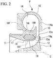
- Fig. 2 is a cross-sectional view of the compressor according to the first embodiment of the present invention.
- the compressor casing 10 forms a wheel inlet flow passage (an inlet flow passage) 11, a wheel flow passage 12, the diffuser 13, and a scroll 14.
- the wheel inlet flow passage 11 is formed, for example, between an intake pipe (not shown) extending from an air cleaner box or the like and the wheel flow passage 12.
- the wheel inlet flow passage 11 includes an inclined section 17 in which the cross-sectional area of the flow passage gradually decreases toward the compressor wheel 3, and a general section 18 which is disposed on a side closer to the compressor wheel 3 than the inclined section 17 and in which a cross-sectional shape of the flow passage does not change.
- the wheel flow passage 12 includes a space which accommodates the compressor wheel 3.
- This wheel flow passage 12 and the compressor wheel 3 form a flow passage through which compressed air flows.
- the wheel flow passage 12 can also be referred to as an accommodating chamber which accommodates the compressor wheel 3.
- a slight gap is formed between a blade section 19 of the compressor wheel 3 and the compressor casing 10. That is, a curved surface 15a is formed along an outer edge 19g of the blade section 19 at a position of the compressor casing 10 facing the blade section 19.
- the wheel flow passage 12 is formed to be curved so that a diameter gradually increases from the side close to the wheel inlet flow passage 11 toward the turbine T side and an increase rate of the diameter expansion gradually increases.
- the diffuser 13 extends radially outward from an outermost circumferential section 12a of the wheel flow passage 12, with the central axis C as the center.
- the diffuser 13 for example, converts kinetic energy of the air compressed by the compressor wheel 3 into pressure energy.
- the diffuser 13 connects the wheel inlet flow passage 11 and the scroll 14.
- the scroll 14 further converts the kinetic energy of the air flowing in from the diffuser 13 into pressure energy and discharges the air to the outside of the compressor casing 10.
- the air discharged via the scroll 14 is supplied to a cylinder or the like of an engine (not shown).
- the scroll 14 is formed in a circular shape in the cross section shown in Fig. 2 , and connected to the diffuser 13 at an end section 14a on the side closest to the turbine T.
- the scroll 14 is formed at a position overlapping the compressor wheel 3 in the direction in which the central axis C extends, and extends in a circumferential direction around the central axis C.
- the cross-sectional area of the scroll 14 thus formed is gradually enlarged toward a discharge port (not shown) of the compressor P.
- Fig. 3 is a flow chart of a method of manufacturing the casing for the rotating machine according to a first embodiment of the present invention.
- the compressor casing 10 is formed by a metal lamination method, using a metallic material such as an aluminum alloy.
- the metal lamination method sequentially repeats a step S1 of spreading the material powder to a predetermined thickness to form a material powder layer, and a step S2 of irradiating the material powder layer with a melting beam.
- the material powder layer is formed by spreading a material powder made of a metallic material such as aluminum alloy for forming the compressor casing 10 to a predetermined thickness of, for example, 30 to 50 ⁇ m.
- step S2 of irradiating the material powder with the melting beam the material powder layer is irradiated with the melting beam having energy for melting the material powder such as a laser beam and an electron beam.
- the material powder melts.
- the irradiation with the melting beam is stopped, the material powder is cooled and solidified to form a metal layer.
- the irradiation range to the material powder layer with the melting beam is set to be in a range corresponding to the cross-sectional shape of the compressor casing 10.
- the metal layer forming a part of the compressor casing 10 is formed to have a predetermined thickness.
- a high-porosity section 16H is formed in a part of the compressor casing 10.
- the high-porosity section 16H suppresses heat transfer from the wheel flow passage 12, the diffuser 13 and the scroll 14 to the wheel inlet flow passage 11.
- the high-porosity section 16H is, for example, formed continuously in the circumferential direction on the outer circumferential side of the general section 18 of the wheel inlet flow passage 11.
- the high-porosity section 16H is not exposed to an inner circumferential surface 18f of the general section 18, but is formed in a region on the outer circumferential side of the inner circumferential surface 18f by a predetermined dimension.
- the high-porosity section 16H is formed so that the porosity thereof is higher than in a low-porosity section (the main section, and the remaining section) 16L which forms a section other than the high-porosity section 16H.
- the low-porosity section 16L and the high-porosity section 16H can be formed, by adjusting the output, the beam scanning speed, the beam scanning line width and the like of the melting beam irradiated in the step of irradiating the material powder with the melting beam, when the compressor casing 10 is formed by the metal lamination method.
- the output of the melting beam is set such that the material powder layer made of the spread material powder is completely melted, the material powder is cooled and solidified after completely melted, and the low-porosity section 16L having a porosity smaller than 5% is formed.
- the output of the melting beam is set, for example, to be weak such that the spread material powder is not completely melted but a part thereof remains in an unmelted state
- the high-porosity section 16H having a porosity of, for example, 5% or more is formed.
- the high-porosity section 16H for example, only the surface of the material powder may be melted and the inner side rather than the surface may be in an unmelted state. In this way, since the surface of the high-porosity section 16H is melted, while maintaining the shape of each material powder, the high-porosity section 16H can be formed in a porous shape in which a large number of cavities are formed between the material powders, while a plurality of material powders are bound to each other.
- the material powder may remain completely unmelted, that is, remain as the material powder.
- a section for forming the surrounding low-porosity section 16L is irradiated with a melting beam
- a section for forming the high-porosity section 16H is not irradiated with the melting beam, and the material powder remains unmelted.
- a molten metallic material (molten metal) is not poured into a metal mold as in the casting or the die casting method.
- molten metal molten metal
- the material powder may spread and the melting beam may be irradiated, it is possible to make the thickness 4 mm or less.
- an outer circumferential wall 10F of the compressor casing 10 can be reduced in thickness.
- the outer circumferential surface of the wheel flow passage 12 may be reduced in thickness at a plurality of positions spaced apart from each other in the circumferential direction.
- the compressor casing 10 includes a low-porosity section 16L and a high-porosity section 16H formed of a metallic material.
- the high-porosity section 16H has high porosity in contrast to the low-porosity section 16L of the compressor casing 10, the thermal conductivity decreases.
- the high-porosity section 16H can have a cavity. As a result, the high-porosity section 16H has low thermal conductivity.
- the high-porosity section 16H can be set such that powder made of a metallic material is present. As a result, the high-porosity section 16H has low density, high porosity, and low thermal conductivity.
- the high-porosity section 16H as described above may be formed at least in an unmelted state of the material powder at the time of irradiation with the melting beam and can be easily formed.
- the high-porosity section 16H is formed between the scroll 14 and the wheel inlet flow passage 11 in the compressor casing 10 of the compressor P.
- the compressor casing 10 can be reduced in thickness as compared with the case where the compressor casing 10 is formed by the casting or the die casting.
- the high-porosity section 16H is formed on the outer circumferential side of the general section 18 of the wheel inlet flow passage 11, but it is not limited thereto.
- Fig. 4 is a cross-sectional view corresponding to Fig. 2 in a first modified example of the first embodiment of the present invention.
- a high-porosity section 116H may continuously form the wheel inlet flow passage 11 and the wheel flow passage 12, and the wheel inlet flow passage 11 includes the inclined section 17 and the general section 18 of the compressor casing 10.
- the high-porosity sections 16H and 116H are formed continuously around the entire circumference in the circumferential direction, but the configuration is not limited thereto.
- the high-porosity sections 16H and 116H may be provided at a plurality of positions spaced apart in the circumferential direction.
- a turbocharger (rotating machine) 1B includes a turbine wheel 2, a compressor wheel 3, a rotating shaft 4, journal bearings 5A and 5B, and a bearing housing 6.
- the turbine T includes a turbine casing (casing) 31 which accommodates the turbine wheel 2.
- the turbine casing 31 is attached to one end side of the bearing housing 6 via a mounting bracket 32.
- the turbine casing 31 has an opening 31a at a position facing the bearing housing 6.
- a turbine wheel 2 having a plurality of turbine blades 2w in a circumferential direction is accommodated in the opening 31a.
- Fig. 5 is a cross-sectional view of the turbine according to the second embodiment of the present invention.
- the turbine casing 31 includes a gas introduction section (not shown), a scroll flow passage 34, and an exhaust section 35.
- the gas introduction section (not shown) sends a part of the exhaust gas discharged from the engine (not shown) into the turbine casing 31.
- the scroll flow passage 34 is continuously formed in the circumferential direction to surround the outer circumferential side of the turbine wheel 2, continuously with the gas introduction section (not shown).
- the scroll flow passage 34 is provided at least in a part in the circumferential direction thereof to face the outer circumferential section of the turbine wheel 2, and forms a flow passage through which the exhaust gas for rotationally driving the turbine wheel 2 flows.
- the exhaust gas flowing in from the gas introduction section 33 flows on the outer circumferential side of the turbine wheel 2 along the scroll flow passage 34 in the circumferential direction.
- the turbine wheel 2 is rotationally driven.
- the flow direction of the exhaust gas changes by hitting the turbine blades 2w on the outer circumferential side of the turbine wheel 2.
- the exhaust gas in which the flow direction changes by the turbine blade 2w is discharged into the exhaust section 35 from the inner circumferential side of the turbine wheel 2.
- the exhaust section 35 is formed in a cylindrical shape which continues along the central axis C in a direction away from the bearing housing 6.
- the exhaust section 35 has a tapered section 35t in which an inner diameter gradually increases as it goes away from the bearing housing 6, and a straight section 35s provided on the downstream side of the tapered section 35t and having a constant inner diameter.
- the exhaust gas flows in the exhaust section 35 in a direction away from the bearing housing 6 along the central axis C.
- a high-porosity section 36H is formed in a part of the turbine casing 31 in a part of the turbine casing 31, a high-porosity section 36H is formed.
- a high-porosity section 36H is formed continuously, for example, over an outer circumferential wall section 34w of the scroll flow passage 34 and the tapered section 35t and the straight section 35s of the exhaust section 35.
- the high-porosity section 36H is formed continuously in the circumferential direction of the turbine casing 31.
- the high-porosity section 36H is formed so as not to be exposed to the outer circumferential surface 31f and the inner circumferential surface 31g of the turbine casing 31.
- the high-porosity section 36H suppresses heat conduction from the outer circumferential surface of the turbine casing 31 to the outside.
- the high-porosity section 36H is formed to have a porosity higher than a low-porosity section (main section) 36L that forms a portion other than the high-porosity section 36H.
- the low-porosity section 36L and the high-porosity section 36H can be formed by the above-described metal lamination method.
- the low-porosity section 36L and the high-porosity section 36H can adjust the output of the melting beam to be irradiated, the beam scanning speed, and the beam scanning line width.
- the thermal conductivity decreases.
- the high-porosity section 36H can be formed on the outer circumferential section of the turbine casing 31.
- the outer circumferential section of the turbine casing 31 is, for example, a portion on the outer side (an outer circumferential side) rather than the center of the turbine casing 31 in the thickness direction.
- Fig. 6 is a cross-sectional view corresponding to Fig. 5 in the first modified example of the second embodiment of the present invention.
- the high-porosity section 136H may be formed, for example, only on the outer circumferential wall section 34w of the scroll flow passage 34. More specifically, the high-porosity section 136H may be formed only on the scroll flow passage 34 of the turbine casing 31, without being formed in the exhaust section 35 or the like.
- the high-porosity section 136H is formed on the outer circumferential wall section 34w of the scroll flow passage 34, it is possible to suppress the exhaust gas flowing through the scroll flow passage 34 from being released via the outer circumferential wall section 34w of the scroll flow passage 34. As a result, it is possible to suppress the temperature decrease of the exhaust gas sent to the turbine wheel 2, and to suppress the reduction in output of the turbine T.
- Fig. 7 is a cross-sectional view corresponding to Fig. 5 in a second modified example of the second embodiment of the present invention.
- a high-porosity section 236H may be provided, for example, only on the tapered section 35t and the straight section 35s of the exhaust section 35.
- the second modified example it is possible to suppress the heat of the exhaust gas flowing through the exhaust section 35 from being released via the exhaust section 35. As a result, exhaust gas having a higher temperature can be sent to the catalyst provided on the downstream side of the exhaust section 35. As a result, the catalyst can function more efficiently.
- the present invention is not limited to this configuration.
- the high-porosity sections 36H, 136H and 236H may be provided at a plurality of positions spaced apart in the circumferential direction.
- the present invention is not limited to the above-described embodiments, and the design can be changed within the scope that does not depart from the gist of the present invention.
- the powder may be removed from the cavity. In this case, it is possible to remove the powder by forming holes or the like for powder removal in the casing.
- an open type impeller has been described as an example.
- the impeller is not limited to the open type impeller, but may be, for example, a closed type impeller integrally including a cover part.
- turbochargers 1A and 1B have been described as examples of rotating machines.
- the rotating machine is not limited to a turbocharger, but may be, for example, a supercharger, a turbine engine or the like.
- the present invention can be applied to a rotating machine and a method of manufacturing the casing for the rotating machine. According to the present invention, heat transfer through the casing can be suppressed and the performance of the rotating machine can be improved.
Landscapes
- Engineering & Computer Science (AREA)
- Chemical & Material Sciences (AREA)
- Mechanical Engineering (AREA)
- General Engineering & Computer Science (AREA)
- Materials Engineering (AREA)
- Physics & Mathematics (AREA)
- Manufacturing & Machinery (AREA)
- Combustion & Propulsion (AREA)
- Optics & Photonics (AREA)
- Plasma & Fusion (AREA)
- Chemical Kinetics & Catalysis (AREA)
- General Chemical & Material Sciences (AREA)
- Automation & Control Theory (AREA)
- Thermal Sciences (AREA)
- Supercharger (AREA)
- Structures Of Non-Positive Displacement Pumps (AREA)
Abstract
Description
- The present invention relates to a rotating machine, and a method for manufacturing a casing for the rotating machine.
- For example, as disclosed in
Patent Document 1, in many cases, a casing for forming an outer shell of a rotating machine, such as a compressor casing of a turbocharger, is made of an aluminum alloy and is formed by casting or die casting. An aluminum alloy has a light weight, a low cost, and high thermal conductivity. - [Patent Document 1] Japanese Unexamined Patent Application, First Publication No.
2001-234753 - In the turbocharger described in
Patent Document 1, the temperature and pressure of air rises by an impeller. At this time, since the compressor casing is made of a material having high thermal conductivity, there is a possibility that the heat of the air heated by the impeller is transferred to the intake air via the compressor casing. When the heat is transferred to the intake air in this manner, the intake air temperature rises and the compression performance of the centrifugal compressor deteriorates. - In the turbocharger, heat of exhaust gas in the turbine is released from the turbine casing made of a material with high thermal conductivity. Hereupon, the turbine output deteriorates.
- An object of the present invention is to provide a rotating machine and a method of manufacturing a casing for the rotating machine capable of suppressing the heat transfer via the casing and improving the performance of the rotating machine.
- According to a first aspect of the present invention, there is provided a rotating machine including: a rotating body configured to rotate around a central axis, and a casing configured to accommodate at least a part of the rotating body. The casing includes a main section made of a metallic material, and a high-porosity section made of the same material as the main section and having a porosity higher than the main section.
- According to such a configuration, since the high-porosity section has a high porosity in contrast to the main section of the casing, the thermal conductivity decreases. By partially providing such a high-porosity section, it is possible to use the main section to main the necessary rigidity, while partially controlling the thermal conductivity of the casing.
- According to a second aspect of the present invention, in the rotating machine according to the first aspect, the high-porosity section may have a cavity.
- In this way, by having the cavity, the high-porosity section has low thermal conductivity. Such a cavity can be formed, for example, by not completely melting the powder made of the metallic material for forming the casing.
- According to a third aspect of the present invention, in the rotating machine according to the first aspect, powder made of the metallic material may be present in the high-porosity section.
- By causing the powder made of the metallic material for forming the casing to be present in the high-porosity section, the density of the high-porosity section can be decreased and the porosity can be increased. Such a powder can be present in a powder form in the casing, for example, by not completely melting the metallic material for forming the casing.
- According to a fourth aspect of the present invention, in the rotating machine according to the first aspect, the high-porosity section may be provided at a plurality of positions spaced apart in a circumferential direction of the central axis.
- In this way, when the high-porosity section is partially provided spaced apart in the circumferential direction rather than all around the circumference of the casing, thermal conductivity can be suppressed by the high-porosity section. The section other than the high-porosity section is formed by the main section having a porosity lower than the high-porosity section and the strength of the cover of the casing can be secured.
- According to a fifth aspect of the present invention, in the rotating machine according to the first aspect, the rotating machine may be a turbocharger, the casing may be a compressor casing of the turbocharger, and the high-porosity section may be formed between a scroll flow passage formed in the compressor casing and an inlet flow passage.
- Thus, it is possible to suppress the heat of the air, which rises in temperature and pressure by the impeller, from being transmitted to the inlet flow passage side from the scroll flow passage on the outlet side of the compressor. As a result, the suction temperature rise at the inlet side of the compressor is suppressed, and it is possible to suppress the reduction in the pressure ratio and the reduction in efficiency of the compressor.
- According to a sixth aspect of the present invention, in the rotating machine according to the first aspect, the rotating machine may be a turbocharger, the casing may be a turbine casing of the turbocharger, and the high-porosity section may be formed on an outer circumferential section of the turbine casing.
- Thus, it is possible to suppress the heat of the exhaust gas passing through the turbine casing from being released through the turbine casing, by the high-porosity section. Furthermore, by increasing the porosity only on the outer circumferential side of the turbine casing, it is possible to maintain the oxidation resistance of the inner surface of the turbine casing exposed to the high temperature gas.
- According to a seventh aspect of the present invention, there is provided a method for manufacturing the casing for the rotating machine, the method including: forming the casing, by repeating a step of forming a material powder layer by spreading a material powder made of a metallic material for forming the casing, and a step of irradiating a melting beam to melt the material powder, and in the step of melting the material powder, a high-porosity section having a porosity higher than that of the remaining section of the casing is formed in a part of the casing, by adjusting at least one of an output of the melting beam, a beam scanning speed, and a beam scanning line width.
- In this way, it is possible to form a casing including a main section made of a metallic material and a high-porosity section having a porosity higher than that of the main section. In such a casing, since the porosity of the high-porosity section is high, the thermal conductivity partially decreases. By providing such a high-porosity section, it is possible to maintain necessary rigidity by the main section, while partially controlling the thermal conductivity of the casing.
- According to the rotating machine and the method for manufacturing the casing for the rotating machine, it is possible to suppress the heat transfer via the casing and to improve the performance of the rotating machine.
-
-
Fig. 1 is a cross-sectional view of a turbocharger according to first and second embodiments of the present invention. -
Fig. 2 is a cross-sectional view of a compressor according to the first embodiment of the present invention. -
Fig. 3 is a flowchart of a method of manufacturing a casing for a rotating machine according to the first embodiment of the present invention. -
Fig. 4 is a cross-sectional view corresponding toFig. 2 in a first modified example of the first embodiment of the present invention. -
Fig. 5 is a cross-sectional view of a turbine according to a second embodiment of the present invention. -
Fig. 6 is a cross-sectional view corresponding toFig. 5 in the first modified example of the second embodiment of the present invention. -
Fig. 7 is a cross-sectional view corresponding toFig. 5 in a second modified example of the second embodiment of the present invention. - Next, a rotating machine and a method for manufacturing a casing for the rotating machine according to a first embodiment of the present invention will be described with reference to the drawings.
-
Fig. 1 is a cross-sectional view of a turbocharger according to a first embodiment of the present invention. - As shown in
Fig. 1 , a turbocharger (a rotating machine) 1A includes aturbine wheel 2, a compressor wheel (impeller) 3, a rotating shaft (rotating body) 4,journal bearings turbocharger 1A is mounted, for example, in an automobile or the like as an auxiliary machine of an engine in such a posture that the rotating shaft 4 extends in a horizontal direction. Here, an alternate long and short dashed line shown inFig. 1 indicates a central axis C of the rotating shaft 4. - In the
turbocharger 1A, theturbine wheel 2 provided in a turbine T rotates about the central axis C by the exhaust gas flow supplied from an engine (not shown) to the turbine T. - The rotating shaft 4 and the
compressor wheel 3 rotate about the central axis C in accordance with the rotation of theturbine wheel 2. - The bearing housing 6 is supported by a vehicle body or the like via a bracket (not shown), a compressor P, the turbine T, and the like. The bearing housing 6 has bearing accommodating
sections journal bearings journal bearings sections first end section 4a and asecond end section 4b of the rotating shaft 4 protrude to the outside of the bearing housing 6 through theopenings - The
turbine wheel 2 is provided on a first side (a right side inFig. 1 ) of the bearing housing 6 in an axial direction in which the central axis C extends, and thecompressor wheel 3 is provided on a second side (a left side inFig. 1 ) of the bearing housing 6. More specifically, theturbine wheel 2 is provided integrally with thefirst end section 4a of the rotating shaft 4, and thecompressor wheel 3 is coupled by screwing anut 7 onto ascrew section 4n formed at thesecond end section 4b of the rotating shaft 4. Theturbine wheel 2 and thecompressor wheel 3 rotate about the central axis C integrally with the rotating shaft 4. - The compressor P includes a
compressor wheel 3 and a compressor casing (casing) 10. - The
compressor wheel 3 is a so-called impeller, which centrifugally compresses air by rotation of the rotating shaft 4. More specifically, the air (intake air) flowing in from the second side in the direction in which the central axis C extends rises in pressure and temperature, and is sent to adiffuser 13 formed outwardly in a radial direction. -
Fig. 2 is a cross-sectional view of the compressor according to the first embodiment of the present invention. - As shown in
Fig. 2 , thecompressor casing 10 forms a wheel inlet flow passage (an inlet flow passage) 11, awheel flow passage 12, thediffuser 13, and ascroll 14. - The wheel
inlet flow passage 11 is formed, for example, between an intake pipe (not shown) extending from an air cleaner box or the like and thewheel flow passage 12. The wheelinlet flow passage 11 includes aninclined section 17 in which the cross-sectional area of the flow passage gradually decreases toward thecompressor wheel 3, and ageneral section 18 which is disposed on a side closer to thecompressor wheel 3 than theinclined section 17 and in which a cross-sectional shape of the flow passage does not change. - The
wheel flow passage 12 includes a space which accommodates thecompressor wheel 3. Thiswheel flow passage 12 and thecompressor wheel 3 form a flow passage through which compressed air flows. In other words, thewheel flow passage 12 can also be referred to as an accommodating chamber which accommodates thecompressor wheel 3. In thewheel flow passage 12, a slight gap is formed between ablade section 19 of thecompressor wheel 3 and thecompressor casing 10. That is, acurved surface 15a is formed along anouter edge 19g of theblade section 19 at a position of thecompressor casing 10 facing theblade section 19. As a result, thewheel flow passage 12 is formed to be curved so that a diameter gradually increases from the side close to the wheelinlet flow passage 11 toward the turbine T side and an increase rate of the diameter expansion gradually increases. - The
diffuser 13 extends radially outward from an outermostcircumferential section 12a of thewheel flow passage 12, with the central axis C as the center. Thediffuser 13, for example, converts kinetic energy of the air compressed by thecompressor wheel 3 into pressure energy. Thediffuser 13 connects the wheelinlet flow passage 11 and thescroll 14. - The
scroll 14 further converts the kinetic energy of the air flowing in from thediffuser 13 into pressure energy and discharges the air to the outside of thecompressor casing 10. The air discharged via thescroll 14 is supplied to a cylinder or the like of an engine (not shown). Thescroll 14 is formed in a circular shape in the cross section shown inFig. 2 , and connected to thediffuser 13 at anend section 14a on the side closest to the turbine T. Thescroll 14 is formed at a position overlapping thecompressor wheel 3 in the direction in which the central axis C extends, and extends in a circumferential direction around the central axis C. The cross-sectional area of thescroll 14 thus formed is gradually enlarged toward a discharge port (not shown) of the compressor P. -
Fig. 3 is a flow chart of a method of manufacturing the casing for the rotating machine according to a first embodiment of the present invention. - The
compressor casing 10 is formed by a metal lamination method, using a metallic material such as an aluminum alloy. - As shown in
Fig. 3 , the metal lamination method sequentially repeats a step S1 of spreading the material powder to a predetermined thickness to form a material powder layer, and a step S2 of irradiating the material powder layer with a melting beam. - In step S1 of forming the material powder layer, the material powder layer is formed by spreading a material powder made of a metallic material such as aluminum alloy for forming the
compressor casing 10 to a predetermined thickness of, for example, 30 to 50 µm. - In step S2 of irradiating the material powder with the melting beam, the material powder layer is irradiated with the melting beam having energy for melting the material powder such as a laser beam and an electron beam. By being irradiated with the melting beam, the material powder melts. When the irradiation with the melting beam is stopped, the material powder is cooled and solidified to form a metal layer. The irradiation range to the material powder layer with the melting beam is set to be in a range corresponding to the cross-sectional shape of the
compressor casing 10. - When the step S1 of forming the material powder layer and the step S2 of irradiating the material powder with the melting beam are performed for one cycle, the metal layer forming a part of the
compressor casing 10 is formed to have a predetermined thickness. By sequentially repeating the step S1 of forming the material powder layer and the step S2 of irradiating the melting beam, and by sequentially changing the irradiation range with the melting beam in accordance with the cross-sectional shape of thecompressor casing 10, a plurality of metal layers are sequentially laminated to form thecompressor casing 10 having a predetermined shape. - As shown in
Fig. 2 , a high-porosity section 16H is formed in a part of thecompressor casing 10. - The high-
porosity section 16H suppresses heat transfer from thewheel flow passage 12, thediffuser 13 and thescroll 14 to the wheelinlet flow passage 11. The high-porosity section 16H is, for example, formed continuously in the circumferential direction on the outer circumferential side of thegeneral section 18 of the wheelinlet flow passage 11. The high-porosity section 16H is not exposed to an innercircumferential surface 18f of thegeneral section 18, but is formed in a region on the outer circumferential side of the innercircumferential surface 18f by a predetermined dimension. - In the
compressor casing 10, the high-porosity section 16H is formed so that the porosity thereof is higher than in a low-porosity section (the main section, and the remaining section) 16L which forms a section other than the high-porosity section 16H. - When the
compressor casing 10 is formed by the aforementioned metal lamination method, the low-porosity section 16L and the high-porosity section 16H can be formed, by adjusting the output, the beam scanning speed, the beam scanning line width and the like of the melting beam irradiated in the step of irradiating the material powder with the melting beam, when thecompressor casing 10 is formed by the metal lamination method. - For example, if the output of the melting beam is set such that the material powder layer made of the spread material powder is completely melted, the material powder is cooled and solidified after completely melted, and the low-
porosity section 16L having a porosity smaller than 5% is formed. - For example, when the output of the melting beam is set, for example, to be weak such that the spread material powder is not completely melted but a part thereof remains in an unmelted state, the high-
porosity section 16H having a porosity of, for example, 5% or more is formed. - In the high-
porosity section 16H, for example, only the surface of the material powder may be melted and the inner side rather than the surface may be in an unmelted state. In this way, since the surface of the high-porosity section 16H is melted, while maintaining the shape of each material powder, the high-porosity section 16H can be formed in a porous shape in which a large number of cavities are formed between the material powders, while a plurality of material powders are bound to each other. - Here, in the aforementioned high-
porosity section 16H, the material powder may remain completely unmelted, that is, remain as the material powder. For this purpose, for example, a section for forming the surrounding low-porosity section 16L is irradiated with a melting beam, a section for forming the high-porosity section 16H is not irradiated with the melting beam, and the material powder remains unmelted. - In such a metal lamination method, a molten metallic material (molten metal) is not poured into a metal mold as in the casting or the die casting method. In the case of a mold, in order to secure the flowability of the molten metal, there is a need for at least, for example, an approximate 4 mm mold frame recess into which the molten metal is poured. In contrast, in the metal lamination method, since the material powder may spread and the melting beam may be irradiated, it is possible to make the thickness 4 mm or less.
- Therefore, as shown by a two-dot chain line in
Fig. 2 , for example, an outercircumferential wall 10F of thecompressor casing 10 can be reduced in thickness. - By reducing the thickness of the outer
circumferential wall 10F of thecompressor casing 10 for forming thescroll 14 in this manner, it is possible to promote heat radiation of the compressed air whose temperature and pressure have been increased by the rotation of thecompressor wheel 3. Furthermore, the temperature of the metal of thecompressor casing 10 on the side close to the turbine T rises due to the influence of the radiation. However, in thecompressor casing 10, by reducing the thickness of the outercircumferential wall 10F facing the side opposite to the turbine T, the heat radiation effect can be promoted. - Further, in this way, the outer circumferential surface of the
wheel flow passage 12 may be reduced in thickness at a plurality of positions spaced apart from each other in the circumferential direction. - Therefore, according to the above-described first embodiment, the
compressor casing 10 includes a low-porosity section 16L and a high-porosity section 16H formed of a metallic material. With such a configuration, since the high-porosity section 16H has high porosity in contrast to the low-porosity section 16L of thecompressor casing 10, the thermal conductivity decreases. By partially providing the high-porosity section 16H, it is possible to maintain necessary rigidity by the low-porosity section 16L, while partially controlling the thermal conductivity of thecompressor casing 10. - As a result, heat transfer through the
compressor casing 10 can be suppressed, and the performance of theturbocharger 1A can be improved. - Furthermore, according to the first embodiment, the high-
porosity section 16H can have a cavity. As a result, the high-porosity section 16H has low thermal conductivity. - Further, the high-
porosity section 16H can be set such that powder made of a metallic material is present. As a result, the high-porosity section 16H has low density, high porosity, and low thermal conductivity. - The high-
porosity section 16H as described above may be formed at least in an unmelted state of the material powder at the time of irradiation with the melting beam and can be easily formed. - Further, the high-
porosity section 16H is formed between thescroll 14 and the wheelinlet flow passage 11 in thecompressor casing 10 of the compressor P. As a result, it is possible to suppress the heat of the air, in which the temperature and pressure increases by thecompressor wheel 3, from being transmitted to the wheelinlet flow passage 11 side from thescroll 14 on the outlet side of the compressor P. As a result, an increase in the suction temperature at the inlet side of the compressor P is suppressed, and it is possible to suppress a reduction in pressure ratio and a decrease in efficiency of the compressor P. - Furthermore, by forming the
compressor casing 10 using the metal lamination method, thecompressor casing 10 can be reduced in thickness as compared with the case where thecompressor casing 10 is formed by the casting or the die casting. - In this way, by reducing the thickness of the
compressor casing 10, it is possible to promote heat radiation of the air which is increased in temperature by thecompressor wheel 3. - Furthermore, while the temperature of the surface metal rises under the influence of radiation on the side of the
compressor casing 10 close to the turbine T, by reducing the thickness of the outercircumferential wall 10F of thecompressor casing 10 on the side opposite to the turbine T, the heat radiation effect can be promoted. - In the first embodiment, the high-
porosity section 16H is formed on the outer circumferential side of thegeneral section 18 of the wheelinlet flow passage 11, but it is not limited thereto. -
Fig. 4 is a cross-sectional view corresponding toFig. 2 in a first modified example of the first embodiment of the present invention. - For example, as shown in
Fig. 4 , a high-porosity section 116H may continuously form the wheelinlet flow passage 11 and thewheel flow passage 12, and the wheelinlet flow passage 11 includes theinclined section 17 and thegeneral section 18 of thecompressor casing 10. - With such a configuration, heat conduction from the
wheel flow passage 12, thediffuser 13, and thescroll 14 to the wheelinlet flow passage 11 is more effectively suppressed by the high-porosity section 116H. - In the first embodiment, as shown in
FIGS. 2 and4 , the high-porosity sections porosity sections - Next, a second embodiment of the present invention will be described with reference to the drawings. In the description of the second embodiment, the same reference numerals are used for the same parts as in the first embodiment, while referring to
Fig. 1 . Further, a detailed description of the overall configuration of the turbocharger that is common to the configuration described in the first embodiment will not be provided. - As shown in
Fig. 1 , a turbocharger (rotating machine) 1B includes aturbine wheel 2, acompressor wheel 3, a rotating shaft 4,journal bearings - The turbine T includes a turbine casing (casing) 31 which accommodates the
turbine wheel 2. Theturbine casing 31 is attached to one end side of the bearing housing 6 via a mountingbracket 32. Theturbine casing 31 has anopening 31a at a position facing the bearing housing 6. Aturbine wheel 2 having a plurality ofturbine blades 2w in a circumferential direction is accommodated in theopening 31a. -
Fig. 5 is a cross-sectional view of the turbine according to the second embodiment of the present invention. - As shown in
Fig. 5 , theturbine casing 31 includes a gas introduction section (not shown), ascroll flow passage 34, and anexhaust section 35. - The gas introduction section (not shown) sends a part of the exhaust gas discharged from the engine (not shown) into the
turbine casing 31. - The
scroll flow passage 34 is continuously formed in the circumferential direction to surround the outer circumferential side of theturbine wheel 2, continuously with the gas introduction section (not shown). Thescroll flow passage 34 is provided at least in a part in the circumferential direction thereof to face the outer circumferential section of theturbine wheel 2, and forms a flow passage through which the exhaust gas for rotationally driving theturbine wheel 2 flows. - The exhaust gas flowing in from the gas introduction section 33 flows on the outer circumferential side of the
turbine wheel 2 along thescroll flow passage 34 in the circumferential direction. When the exhaust gas flowing along the circumferential direction in this way hits theturbine blade 2w of theturbine wheel 2, theturbine wheel 2 is rotationally driven. The flow direction of the exhaust gas changes by hitting theturbine blades 2w on the outer circumferential side of theturbine wheel 2. The exhaust gas in which the flow direction changes by theturbine blade 2w is discharged into theexhaust section 35 from the inner circumferential side of theturbine wheel 2. - The
exhaust section 35 is formed in a cylindrical shape which continues along the central axis C in a direction away from the bearing housing 6. Theexhaust section 35 has a taperedsection 35t in which an inner diameter gradually increases as it goes away from the bearing housing 6, and astraight section 35s provided on the downstream side of the taperedsection 35t and having a constant inner diameter. The exhaust gas flows in theexhaust section 35 in a direction away from the bearing housing 6 along the central axis C. - In a part of the
turbine casing 31, a high-porosity section 36H is formed. Such a high-porosity section 36H is formed continuously, for example, over an outercircumferential wall section 34w of thescroll flow passage 34 and the taperedsection 35t and thestraight section 35s of theexhaust section 35. The high-porosity section 36H is formed continuously in the circumferential direction of theturbine casing 31. The high-porosity section 36H is formed so as not to be exposed to the outer circumferential surface 31f and the inner circumferential surface 31g of theturbine casing 31. - The high-
porosity section 36H suppresses heat conduction from the outer circumferential surface of theturbine casing 31 to the outside. In theturbine casing 31, the high-porosity section 36H is formed to have a porosity higher than a low-porosity section (main section) 36L that forms a portion other than the high-porosity section 36H. - The low-
porosity section 36L and the high-porosity section 36H can be formed by the above-described metal lamination method. When being formed by the metal lamination method, in the step of irradiating the material powder with the melting beam, the low-porosity section 36L and the high-porosity section 36H can adjust the output of the melting beam to be irradiated, the beam scanning speed, and the beam scanning line width. - In the method of manufacturing the rotating machine and the casing for the rotating machine of this embodiment, since the high-
porosity section 36H has high porosity in contrast to the low-porosity section 36L of theturbine casing 31, the thermal conductivity decreases. By partially providing such a high-porosity section 36H, it is possible to maintain the required rigidity by the low-porosity section 36L, while partially controlling the thermal conductivity of theturbine casing 31. - As a result, heat transfer through the
turbine casing 31 can be suppressed, and the performance of theturbocharger 1B can be improved. - The high-
porosity section 36H can be formed on the outer circumferential section of theturbine casing 31. Here, the outer circumferential section of theturbine casing 31 is, for example, a portion on the outer side (an outer circumferential side) rather than the center of theturbine casing 31 in the thickness direction. By forming the high-porosity section 36H in this manner, it is possible to suppress the heat of the exhaust gas passing through theturbine casing 31 from being released through theturbine casing 31. Further, by forming the high-porosity section 36H having high porosity only on the outer circumferential section of theturbine casing 31, it is possible to maintain the oxidation resistance of the inner surface of theturbine casing 31 exposed to the high temperature gas. Furthermore, since it is possible to suppress heat of the exhaust gas from being released, it is possible to send the exhaust gas having a higher temperature to the catalyst provided downstream of theexhaust section 35. Since the catalyst has temperature dependence, by suppressing the temperature decrease of the exhaust gas temperature, it is possible to make the catalyst function more efficiently. - In the above-described second embodiment, the description has been given for the case in which the high-
porosity section 36H is continuously formed over the outercircumferential wall section 34w of thescroll flow passage 34 and the taperedsection 35t and thestraight section 35s of theexhaust section 35 has been described, but is not limited to this configuration. -
Fig. 6 is a cross-sectional view corresponding toFig. 5 in the first modified example of the second embodiment of the present invention. - As shown in
Fig. 6 , the high-porosity section 136H may be formed, for example, only on the outercircumferential wall section 34w of thescroll flow passage 34. More specifically, the high-porosity section 136H may be formed only on thescroll flow passage 34 of theturbine casing 31, without being formed in theexhaust section 35 or the like. - According to the first modified example, when the high-
porosity section 136H is formed on the outercircumferential wall section 34w of thescroll flow passage 34, it is possible to suppress the exhaust gas flowing through thescroll flow passage 34 from being released via the outercircumferential wall section 34w of thescroll flow passage 34. As a result, it is possible to suppress the temperature decrease of the exhaust gas sent to theturbine wheel 2, and to suppress the reduction in output of the turbine T. -
Fig. 7 is a cross-sectional view corresponding toFig. 5 in a second modified example of the second embodiment of the present invention. - As shown in
Fig. 7 , a high-porosity section 236H may be provided, for example, only on the taperedsection 35t and thestraight section 35s of theexhaust section 35. - According to the second modified example, it is possible to suppress the heat of the exhaust gas flowing through the
exhaust section 35 from being released via theexhaust section 35. As a result, exhaust gas having a higher temperature can be sent to the catalyst provided on the downstream side of theexhaust section 35. As a result, the catalyst can function more efficiently. - In
Figs. 5 to 7 , the description has been of a case in which the high-porosity sections porosity sections - The present invention is not limited to the above-described embodiments, and the design can be changed within the scope that does not depart from the gist of the present invention.
- In the above-described first embodiment, the description has been provided of the case in which the high-
porosity section 16H has cavity in which the powder made of a metallic material is present in an unmelted state. However, in the high-porosity section 16H, the powder may be removed from the cavity. In this case, it is possible to remove the powder by forming holes or the like for powder removal in the casing. - Furthermore, in the above-described embodiment, an open type impeller has been described as an example. However, the impeller is not limited to the open type impeller, but may be, for example, a closed type impeller integrally including a cover part.
- Further, the
turbochargers - The present invention can be applied to a rotating machine and a method of manufacturing the casing for the rotating machine. According to the present invention, heat transfer through the casing can be suppressed and the performance of the rotating machine can be improved.
-
- 1A, 1B Turbocharger (rotating machine)
- 2 Turbine Wheel
- 2w Turbine blade
- 3 Compressor wheel
- 4 Rotating shaft (rotating body)
- 4a First end section
- 4b Second end section
- 4n Screw section
- 5A, 5B journal bearing
- 6 Bearing housing
- 7 Nut
- 10 Compressor casing (casing)
- 10F Outer circumferential wall
- 11 Wheel inlet flow passage (inlet flow passage)
- 12 Wheel flow passage
- 12a Outermost circumferential section
- 13 Diffuser
- 14 Scroll
- 14a End section
- 15a Curved surface
- 16H, 36H, 116H, 136H, 236H high-porosity section
- 16L, 36L Low-porosity section (main section, remaining section)
- 17 Inclined section
- 18 General section
- 18f Inner circumferential surface
- 19 Blade section
- 19g Outer edge
- 31 Turbine casing (casing)
- 31a Opening
- 31f Outer circumferential surface
- 31g Inner circumferential surface
- 32 Mounting bracket
- 34 Scroll flow passage
- 34w Outer circumferential wall section
- 35 Exhaust section
- 35s Straight section
- 35t Tapered section
- 60a, 60b Opening
- 61A, 61B Bearing accommodating section
- C Central axis
- P Compressor
- T Turbine
Claims (7)
- A rotating machine comprising:a rotating body configured to rotate around a central axis, anda casing configured to accommodate at least a part of the rotating body,wherein the casing includes a main section made of a metallic material, and a high-porosity section made of the same material as the main section and having a porosity higher than the main section.
- The rotating machine according to claim 1, wherein the high-porosity section has a cavity.
- The rotating machine according to claim 1, wherein powder made of the metallic material is present in the high-porosity section.
- The rotating machine according to claim 1, wherein the high-porosity section is provided at a plurality of positions spaced apart in a circumferential direction of the central axis.
- The rotating machine according to claim 1, wherein the rotating machine is a turbocharger,
the casing is a compressor casing of the turbocharger, and
the high-porosity section is formed between a scroll flow passage formed in the compressor casing and an inlet flow passage. - The rotating machine according to claim 1, wherein the rotating machine is a turbocharger,
the casing is a turbine casing of the turbocharger, and
the high-porosity section is formed on an outer circumferential section of the turbine casing. - A method for manufacturing the casing for the rotating machine according to any one of claims 1 to 6, the method comprising:forming the casing, by repeating a step of forming a material powder layer by spreading a material powder made of a metallic material for forming the casing, and a step of irradiating the metal powder with a melting beam to melt the material powder; andwherein, in the step of melting the material powder, a high-porosity section having a porosity higher than that of the remaining section of the casing is formed in a part of the casing, by adjusting at least one of an output of the melting beam, a beam scanning speed, and a beam scanning line width.
Applications Claiming Priority (1)
| Application Number | Priority Date | Filing Date | Title |
|---|---|---|---|
| PCT/JP2016/058804 WO2017158837A1 (en) | 2016-03-18 | 2016-03-18 | Rotating machine and method for manufacturing casing for rotating machine |
Publications (3)
| Publication Number | Publication Date |
|---|---|
| EP3412890A1 true EP3412890A1 (en) | 2018-12-12 |
| EP3412890A4 EP3412890A4 (en) | 2019-03-13 |
| EP3412890B1 EP3412890B1 (en) | 2021-05-05 |
Family
ID=59850215
Family Applications (1)
| Application Number | Title | Priority Date | Filing Date |
|---|---|---|---|
| EP16894455.1A Active EP3412890B1 (en) | 2016-03-18 | 2016-03-18 | Rotating machine and method for manufacturing casing for rotating machine |
Country Status (5)
| Country | Link |
|---|---|
| US (1) | US10634042B2 (en) |
| EP (1) | EP3412890B1 (en) |
| JP (1) | JP6640326B2 (en) |
| CN (1) | CN108779709A (en) |
| WO (1) | WO2017158837A1 (en) |
Families Citing this family (3)
| Publication number | Priority date | Publication date | Assignee | Title |
|---|---|---|---|---|
| DE102016207745A1 (en) * | 2016-05-04 | 2017-11-09 | Continental Automotive Gmbh | Turbine housing for a turbocharger of an internal combustion engine and turbocharger |
| JP7002306B2 (en) * | 2017-11-29 | 2022-01-20 | 三菱重工業株式会社 | How to manufacture turbine wheels, turbochargers and turbine wheels |
| DE102020101904A1 (en) * | 2020-01-27 | 2021-07-29 | Röchling Automotive SE & Co. KG | Method for producing an air duct component with an additive production method while changing at least one process parameter during the execution of the method and such an air duct component |
Family Cites Families (21)
| Publication number | Priority date | Publication date | Assignee | Title |
|---|---|---|---|---|
| JPS55149178A (en) * | 1979-05-02 | 1980-11-20 | Ishikawajima Harima Heavy Ind | Composite heat resisting structure of ceramic and metal and its manufacture |
| JPS59118801A (en) * | 1982-12-27 | 1984-07-09 | Toshiba Corp | Production of sintered parts |
| US5980203A (en) | 1996-06-05 | 1999-11-09 | Atlas Compco Comptec | Spark-prevention coating for oxygen compressor shroud |
| US5704759A (en) * | 1996-10-21 | 1998-01-06 | Alliedsignal Inc. | Abrasive tip/abradable shroud system and method for gas turbine compressor clearance control |
| JP2001234753A (en) | 2000-02-24 | 2001-08-31 | Hitachi Ltd | Compressor housing for supercharger |
| JP2003129862A (en) * | 2001-10-23 | 2003-05-08 | Toshiba Corp | Turbine blade production method |
| JP4544398B2 (en) * | 2004-02-06 | 2010-09-15 | トヨタ自動車株式会社 | Injection mold |
| JP2007154750A (en) * | 2005-12-05 | 2007-06-21 | Ishikawajima Harima Heavy Ind Co Ltd | Oxygen compressor |
| JP4655277B2 (en) * | 2006-01-23 | 2011-03-23 | トヨタ自動車株式会社 | Structure |
| ITMI20070665A1 (en) * | 2007-03-30 | 2008-09-30 | Nuovo Pignone Spa | ABRADIBLE AND ANTI-ROUND COATING FOR ROTARY MACHINES IN LUIDO |
| CN201133281Y (en) * | 2007-12-25 | 2008-10-15 | 孙宇 | Turbo-charger |
| JP5665602B2 (en) * | 2011-02-25 | 2015-02-04 | 三菱重工業株式会社 | Multistage turbocharger structure |
| JP2013129899A (en) * | 2011-12-22 | 2013-07-04 | Toyota Motor Corp | Method for manufacturing heat insulating member, and internal combustion engine manufactured therewith |
| ITFI20120035A1 (en) * | 2012-02-23 | 2013-08-24 | Nuovo Pignone Srl | "IMPELLER PRODUCTION FOR TURBO-MACHINES" |
| JP5974886B2 (en) * | 2012-12-21 | 2016-08-23 | トヨタ自動車株式会社 | Turbocharger |
| US20160332371A1 (en) * | 2014-01-22 | 2016-11-17 | United Technologies Corporation | Additive manufacturing system and method of operation |
| JP2015187411A (en) * | 2014-03-26 | 2015-10-29 | 株式会社東芝 | Rotor blade integrated type turbine rotor, steam turbine, and method for manufacturing rotor blade integrated type turbine rotor |
| JP6459272B2 (en) * | 2014-07-23 | 2019-01-30 | 日立金属株式会社 | Alloy structure |
| US10167727B2 (en) * | 2014-08-13 | 2019-01-01 | United Technologies Corporation | Gas turbine engine blade containment system |
| US11359632B2 (en) * | 2014-10-31 | 2022-06-14 | Ingersoll-Rand Industrial U.S., Inc. | Rotary screw compressor rotor having work extraction mechanism |
| US10132185B2 (en) * | 2014-11-07 | 2018-11-20 | Rolls-Royce Corporation | Additive process for an abradable blade track used in a gas turbine engine |
-
2016
- 2016-03-18 US US16/082,866 patent/US10634042B2/en active Active
- 2016-03-18 JP JP2018505204A patent/JP6640326B2/en not_active Expired - Fee Related
- 2016-03-18 CN CN201680083527.2A patent/CN108779709A/en active Pending
- 2016-03-18 WO PCT/JP2016/058804 patent/WO2017158837A1/en active Application Filing
- 2016-03-18 EP EP16894455.1A patent/EP3412890B1/en active Active
Also Published As
| Publication number | Publication date |
|---|---|
| US20190093550A1 (en) | 2019-03-28 |
| JP6640326B2 (en) | 2020-02-05 |
| EP3412890B1 (en) | 2021-05-05 |
| US10634042B2 (en) | 2020-04-28 |
| WO2017158837A1 (en) | 2017-09-21 |
| CN108779709A (en) | 2018-11-09 |
| EP3412890A4 (en) | 2019-03-13 |
| JPWO2017158837A1 (en) | 2019-01-10 |
Similar Documents
| Publication | Publication Date | Title |
|---|---|---|
| JP4697492B2 (en) | Electric turbocharger | |
| US10662806B2 (en) | Compressor, turbine and turbocharger | |
| JP5933552B2 (en) | Exhaust turbocharger | |
| EP2617961B1 (en) | Radial turbine | |
| EP3412890B1 (en) | Rotating machine and method for manufacturing casing for rotating machine | |
| EP2889455B1 (en) | Water cooled turbocharger with heat insulation | |
| EP3409920B1 (en) | Turbocharger | |
| JP2003314201A (en) | Moving blade used in turbomachine | |
| JP2009544882A (en) | Turbine housing for turbocharger | |
| JP2009281323A (en) | Housing of compressor | |
| KR20150138272A (en) | Turbine wheel of an exhaust-gas turbocharger | |
| KR101055231B1 (en) | Turbine housing | |
| JP5797724B2 (en) | Exhaust gas turbocharger | |
| JP2008196327A (en) | Turbocharger | |
| CN108474390B (en) | Centrifugal compressor and supercharger | |
| CN103052778A (en) | Scroll portion structure for radial turbine or diagonal flow turbine | |
| EP3764525B1 (en) | Electric motor and housing with integrated heat exchanger channels | |
| JP2014050133A (en) | Rotor, electric motor, and supercharger | |
| JP2015224600A (en) | Electric supercharger | |
| JP2014034957A (en) | Bearing housing for supercharger | |
| WO2019138497A1 (en) | Turbine rotor blade, turbo charger, and turbine rotor blade manufacturing method | |
| JP7002306B2 (en) | How to manufacture turbine wheels, turbochargers and turbine wheels | |
| JP2004143937A (en) | Housing for supercharger and its manufacturing method | |
| EP3434908A1 (en) | Impeller, rotary machine, and turbocharger | |
| CN110234855B (en) | Housing of turbine for exhaust turbocharger, and manufacturing method |
Legal Events
| Date | Code | Title | Description |
|---|---|---|---|
| STAA | Information on the status of an ep patent application or granted ep patent |
Free format text: STATUS: THE INTERNATIONAL PUBLICATION HAS BEEN MADE |
|
| PUAI | Public reference made under article 153(3) epc to a published international application that has entered the european phase |
Free format text: ORIGINAL CODE: 0009012 |
|
| STAA | Information on the status of an ep patent application or granted ep patent |
Free format text: STATUS: REQUEST FOR EXAMINATION WAS MADE |
|
| 17P | Request for examination filed |
Effective date: 20180907 |
|
| AK | Designated contracting states |
Kind code of ref document: A1 Designated state(s): AL AT BE BG CH CY CZ DE DK EE ES FI FR GB GR HR HU IE IS IT LI LT LU LV MC MK MT NL NO PL PT RO RS SE SI SK SM TR |
|
| AX | Request for extension of the european patent |
Extension state: BA ME |
|
| A4 | Supplementary search report drawn up and despatched |
Effective date: 20190213 |
|
| RIC1 | Information provided on ipc code assigned before grant |
Ipc: F02C 6/12 20060101ALI20190207BHEP Ipc: F04D 29/02 20060101ALI20190207BHEP Ipc: F04D 29/58 20060101ALI20190207BHEP Ipc: F04D 29/42 20060101ALI20190207BHEP Ipc: F02B 39/00 20060101AFI20190207BHEP |
|
| DAV | Request for validation of the european patent (deleted) | ||
| DAX | Request for extension of the european patent (deleted) | ||
| STAA | Information on the status of an ep patent application or granted ep patent |
Free format text: STATUS: EXAMINATION IS IN PROGRESS |
|
| 17Q | First examination report despatched |
Effective date: 20191125 |
|
| GRAP | Despatch of communication of intention to grant a patent |
Free format text: ORIGINAL CODE: EPIDOSNIGR1 |
|
| STAA | Information on the status of an ep patent application or granted ep patent |
Free format text: STATUS: GRANT OF PATENT IS INTENDED |
|
| RIC1 | Information provided on ipc code assigned before grant |
Ipc: B33Y 50/02 20150101ALI20201022BHEP Ipc: F01D 25/26 20060101ALI20201022BHEP Ipc: F02C 6/12 20060101ALI20201022BHEP Ipc: F02B 39/00 20060101AFI20201022BHEP Ipc: B33Y 80/00 20150101ALI20201022BHEP Ipc: B29C 64/153 20170101ALI20201022BHEP Ipc: F02B 37/00 20060101ALI20201022BHEP Ipc: F04D 29/58 20060101ALI20201022BHEP Ipc: F04D 29/42 20060101ALI20201022BHEP Ipc: B29C 64/393 20170101ALI20201022BHEP Ipc: B22F 3/105 20060101ALI20201022BHEP Ipc: F04D 29/02 20060101ALI20201022BHEP |
|
| INTG | Intention to grant announced |
Effective date: 20201117 |
|
| INTG | Intention to grant announced |
Effective date: 20201124 |
|
| GRAS | Grant fee paid |
Free format text: ORIGINAL CODE: EPIDOSNIGR3 |
|
| GRAA | (expected) grant |
Free format text: ORIGINAL CODE: 0009210 |
|
| STAA | Information on the status of an ep patent application or granted ep patent |
Free format text: STATUS: THE PATENT HAS BEEN GRANTED |
|
| AK | Designated contracting states |
Kind code of ref document: B1 Designated state(s): AL AT BE BG CH CY CZ DE DK EE ES FI FR GB GR HR HU IE IS IT LI LT LU LV MC MK MT NL NO PL PT RO RS SE SI SK SM TR |
|
| REG | Reference to a national code |
Ref country code: GB Ref legal event code: FG4D |
|
| REG | Reference to a national code |
Ref country code: CH Ref legal event code: EP |
|
| REG | Reference to a national code |
Ref country code: AT Ref legal event code: REF Ref document number: 1390073 Country of ref document: AT Kind code of ref document: T Effective date: 20210515 |
|
| REG | Reference to a national code |
Ref country code: IE Ref legal event code: FG4D |
|
| REG | Reference to a national code |
Ref country code: DE Ref legal event code: R096 Ref document number: 602016057617 Country of ref document: DE |
|
| REG | Reference to a national code |
Ref country code: LT Ref legal event code: MG9D |
|
| REG | Reference to a national code |
Ref country code: AT Ref legal event code: MK05 Ref document number: 1390073 Country of ref document: AT Kind code of ref document: T Effective date: 20210505 |
|
| PG25 | Lapsed in a contracting state [announced via postgrant information from national office to epo] |
Ref country code: FI Free format text: LAPSE BECAUSE OF FAILURE TO SUBMIT A TRANSLATION OF THE DESCRIPTION OR TO PAY THE FEE WITHIN THE PRESCRIBED TIME-LIMIT Effective date: 20210505 Ref country code: LT Free format text: LAPSE BECAUSE OF FAILURE TO SUBMIT A TRANSLATION OF THE DESCRIPTION OR TO PAY THE FEE WITHIN THE PRESCRIBED TIME-LIMIT Effective date: 20210505 Ref country code: HR Free format text: LAPSE BECAUSE OF FAILURE TO SUBMIT A TRANSLATION OF THE DESCRIPTION OR TO PAY THE FEE WITHIN THE PRESCRIBED TIME-LIMIT Effective date: 20210505 Ref country code: BG Free format text: LAPSE BECAUSE OF FAILURE TO SUBMIT A TRANSLATION OF THE DESCRIPTION OR TO PAY THE FEE WITHIN THE PRESCRIBED TIME-LIMIT Effective date: 20210805 Ref country code: AT Free format text: LAPSE BECAUSE OF FAILURE TO SUBMIT A TRANSLATION OF THE DESCRIPTION OR TO PAY THE FEE WITHIN THE PRESCRIBED TIME-LIMIT Effective date: 20210505 |
|
| PG25 | Lapsed in a contracting state [announced via postgrant information from national office to epo] |
Ref country code: IS Free format text: LAPSE BECAUSE OF FAILURE TO SUBMIT A TRANSLATION OF THE DESCRIPTION OR TO PAY THE FEE WITHIN THE PRESCRIBED TIME-LIMIT Effective date: 20210905 Ref country code: GR Free format text: LAPSE BECAUSE OF FAILURE TO SUBMIT A TRANSLATION OF THE DESCRIPTION OR TO PAY THE FEE WITHIN THE PRESCRIBED TIME-LIMIT Effective date: 20210806 Ref country code: LV Free format text: LAPSE BECAUSE OF FAILURE TO SUBMIT A TRANSLATION OF THE DESCRIPTION OR TO PAY THE FEE WITHIN THE PRESCRIBED TIME-LIMIT Effective date: 20210505 Ref country code: SE Free format text: LAPSE BECAUSE OF FAILURE TO SUBMIT A TRANSLATION OF THE DESCRIPTION OR TO PAY THE FEE WITHIN THE PRESCRIBED TIME-LIMIT Effective date: 20210505 Ref country code: RS Free format text: LAPSE BECAUSE OF FAILURE TO SUBMIT A TRANSLATION OF THE DESCRIPTION OR TO PAY THE FEE WITHIN THE PRESCRIBED TIME-LIMIT Effective date: 20210505 Ref country code: PL Free format text: LAPSE BECAUSE OF FAILURE TO SUBMIT A TRANSLATION OF THE DESCRIPTION OR TO PAY THE FEE WITHIN THE PRESCRIBED TIME-LIMIT Effective date: 20210505 Ref country code: NO Free format text: LAPSE BECAUSE OF FAILURE TO SUBMIT A TRANSLATION OF THE DESCRIPTION OR TO PAY THE FEE WITHIN THE PRESCRIBED TIME-LIMIT Effective date: 20210805 Ref country code: PT Free format text: LAPSE BECAUSE OF FAILURE TO SUBMIT A TRANSLATION OF THE DESCRIPTION OR TO PAY THE FEE WITHIN THE PRESCRIBED TIME-LIMIT Effective date: 20210906 |
|
| REG | Reference to a national code |
Ref country code: NL Ref legal event code: MP Effective date: 20210505 |
|
| PG25 | Lapsed in a contracting state [announced via postgrant information from national office to epo] |
Ref country code: NL Free format text: LAPSE BECAUSE OF FAILURE TO SUBMIT A TRANSLATION OF THE DESCRIPTION OR TO PAY THE FEE WITHIN THE PRESCRIBED TIME-LIMIT Effective date: 20210505 |
|
| PG25 | Lapsed in a contracting state [announced via postgrant information from national office to epo] |
Ref country code: SK Free format text: LAPSE BECAUSE OF FAILURE TO SUBMIT A TRANSLATION OF THE DESCRIPTION OR TO PAY THE FEE WITHIN THE PRESCRIBED TIME-LIMIT Effective date: 20210505 Ref country code: SM Free format text: LAPSE BECAUSE OF FAILURE TO SUBMIT A TRANSLATION OF THE DESCRIPTION OR TO PAY THE FEE WITHIN THE PRESCRIBED TIME-LIMIT Effective date: 20210505 Ref country code: CZ Free format text: LAPSE BECAUSE OF FAILURE TO SUBMIT A TRANSLATION OF THE DESCRIPTION OR TO PAY THE FEE WITHIN THE PRESCRIBED TIME-LIMIT Effective date: 20210505 Ref country code: DK Free format text: LAPSE BECAUSE OF FAILURE TO SUBMIT A TRANSLATION OF THE DESCRIPTION OR TO PAY THE FEE WITHIN THE PRESCRIBED TIME-LIMIT Effective date: 20210505 Ref country code: EE Free format text: LAPSE BECAUSE OF FAILURE TO SUBMIT A TRANSLATION OF THE DESCRIPTION OR TO PAY THE FEE WITHIN THE PRESCRIBED TIME-LIMIT Effective date: 20210505 Ref country code: RO Free format text: LAPSE BECAUSE OF FAILURE TO SUBMIT A TRANSLATION OF THE DESCRIPTION OR TO PAY THE FEE WITHIN THE PRESCRIBED TIME-LIMIT Effective date: 20210505 Ref country code: ES Free format text: LAPSE BECAUSE OF FAILURE TO SUBMIT A TRANSLATION OF THE DESCRIPTION OR TO PAY THE FEE WITHIN THE PRESCRIBED TIME-LIMIT Effective date: 20210505 |
|
| REG | Reference to a national code |
Ref country code: DE Ref legal event code: R097 Ref document number: 602016057617 Country of ref document: DE |
|
| PLBE | No opposition filed within time limit |
Free format text: ORIGINAL CODE: 0009261 |
|
| STAA | Information on the status of an ep patent application or granted ep patent |
Free format text: STATUS: NO OPPOSITION FILED WITHIN TIME LIMIT |
|
| 26N | No opposition filed |
Effective date: 20220208 |
|
| PG25 | Lapsed in a contracting state [announced via postgrant information from national office to epo] |
Ref country code: IS Free format text: LAPSE BECAUSE OF FAILURE TO SUBMIT A TRANSLATION OF THE DESCRIPTION OR TO PAY THE FEE WITHIN THE PRESCRIBED TIME-LIMIT Effective date: 20210905 Ref country code: AL Free format text: LAPSE BECAUSE OF FAILURE TO SUBMIT A TRANSLATION OF THE DESCRIPTION OR TO PAY THE FEE WITHIN THE PRESCRIBED TIME-LIMIT Effective date: 20210505 |
|
| PG25 | Lapsed in a contracting state [announced via postgrant information from national office to epo] |
Ref country code: IT Free format text: LAPSE BECAUSE OF FAILURE TO SUBMIT A TRANSLATION OF THE DESCRIPTION OR TO PAY THE FEE WITHIN THE PRESCRIBED TIME-LIMIT Effective date: 20210505 |
|
| PG25 | Lapsed in a contracting state [announced via postgrant information from national office to epo] |
Ref country code: MC Free format text: LAPSE BECAUSE OF FAILURE TO SUBMIT A TRANSLATION OF THE DESCRIPTION OR TO PAY THE FEE WITHIN THE PRESCRIBED TIME-LIMIT Effective date: 20210505 |
|
| REG | Reference to a national code |
Ref country code: CH Ref legal event code: PL |
|
| GBPC | Gb: european patent ceased through non-payment of renewal fee |
Effective date: 20220318 |
|
| REG | Reference to a national code |
Ref country code: BE Ref legal event code: MM Effective date: 20220331 |
|
| PG25 | Lapsed in a contracting state [announced via postgrant information from national office to epo] |
Ref country code: LU Free format text: LAPSE BECAUSE OF NON-PAYMENT OF DUE FEES Effective date: 20220318 Ref country code: LI Free format text: LAPSE BECAUSE OF NON-PAYMENT OF DUE FEES Effective date: 20220331 Ref country code: IE Free format text: LAPSE BECAUSE OF NON-PAYMENT OF DUE FEES Effective date: 20220318 Ref country code: GB Free format text: LAPSE BECAUSE OF NON-PAYMENT OF DUE FEES Effective date: 20220318 Ref country code: FR Free format text: LAPSE BECAUSE OF NON-PAYMENT OF DUE FEES Effective date: 20220331 Ref country code: CH Free format text: LAPSE BECAUSE OF NON-PAYMENT OF DUE FEES Effective date: 20220331 |
|
| PG25 | Lapsed in a contracting state [announced via postgrant information from national office to epo] |
Ref country code: BE Free format text: LAPSE BECAUSE OF NON-PAYMENT OF DUE FEES Effective date: 20220331 |
|
| PG25 | Lapsed in a contracting state [announced via postgrant information from national office to epo] |
Ref country code: HU Free format text: LAPSE BECAUSE OF FAILURE TO SUBMIT A TRANSLATION OF THE DESCRIPTION OR TO PAY THE FEE WITHIN THE PRESCRIBED TIME-LIMIT; INVALID AB INITIO Effective date: 20160318 |
|
| PG25 | Lapsed in a contracting state [announced via postgrant information from national office to epo] |
Ref country code: MK Free format text: LAPSE BECAUSE OF FAILURE TO SUBMIT A TRANSLATION OF THE DESCRIPTION OR TO PAY THE FEE WITHIN THE PRESCRIBED TIME-LIMIT Effective date: 20210505 Ref country code: CY Free format text: LAPSE BECAUSE OF FAILURE TO SUBMIT A TRANSLATION OF THE DESCRIPTION OR TO PAY THE FEE WITHIN THE PRESCRIBED TIME-LIMIT Effective date: 20210505 |
|
| PGFP | Annual fee paid to national office [announced via postgrant information from national office to epo] |
Ref country code: DE Payment date: 20240130 Year of fee payment: 9 |