JP5933552B2 - Exhaust turbocharger - Google Patents
Exhaust turbocharger Download PDFInfo
- Publication number
- JP5933552B2 JP5933552B2 JP2013526000A JP2013526000A JP5933552B2 JP 5933552 B2 JP5933552 B2 JP 5933552B2 JP 2013526000 A JP2013526000 A JP 2013526000A JP 2013526000 A JP2013526000 A JP 2013526000A JP 5933552 B2 JP5933552 B2 JP 5933552B2
- Authority
- JP
- Japan
- Prior art keywords
- oil
- exhaust turbocharger
- bearing housing
- chamber
- turbine
- Prior art date
- Legal status (The legal status is an assumption and is not a legal conclusion. Google has not performed a legal analysis and makes no representation as to the accuracy of the status listed.)
- Expired - Fee Related
Links
- 238000005192 partition Methods 0.000 claims description 12
- 230000002093 peripheral effect Effects 0.000 claims description 6
- 238000007789 sealing Methods 0.000 claims description 5
- 230000015572 biosynthetic process Effects 0.000 description 3
- 238000005266 casting Methods 0.000 description 2
- 238000010586 diagram Methods 0.000 description 2
- 238000003754 machining Methods 0.000 description 2
- 230000007704 transition Effects 0.000 description 2
- 230000001419 dependent effect Effects 0.000 description 1
- 230000000694 effects Effects 0.000 description 1
- 239000003595 mist Substances 0.000 description 1
- 239000013589 supplement Substances 0.000 description 1
Images


Classifications
-
- F—MECHANICAL ENGINEERING; LIGHTING; HEATING; WEAPONS; BLASTING
- F01—MACHINES OR ENGINES IN GENERAL; ENGINE PLANTS IN GENERAL; STEAM ENGINES
- F01D—NON-POSITIVE DISPLACEMENT MACHINES OR ENGINES, e.g. STEAM TURBINES
- F01D25/00—Component parts, details, or accessories, not provided for in, or of interest apart from, other groups
- F01D25/18—Lubricating arrangements
-
- F—MECHANICAL ENGINEERING; LIGHTING; HEATING; WEAPONS; BLASTING
- F16—ENGINEERING ELEMENTS AND UNITS; GENERAL MEASURES FOR PRODUCING AND MAINTAINING EFFECTIVE FUNCTIONING OF MACHINES OR INSTALLATIONS; THERMAL INSULATION IN GENERAL
- F16C—SHAFTS; FLEXIBLE SHAFTS; ELEMENTS OR CRANKSHAFT MECHANISMS; ROTARY BODIES OTHER THAN GEARING ELEMENTS; BEARINGS
- F16C35/00—Rigid support of bearing units; Housings, e.g. caps, covers
- F16C35/02—Rigid support of bearing units; Housings, e.g. caps, covers in the case of sliding-contact bearings
-
- F—MECHANICAL ENGINEERING; LIGHTING; HEATING; WEAPONS; BLASTING
- F01—MACHINES OR ENGINES IN GENERAL; ENGINE PLANTS IN GENERAL; STEAM ENGINES
- F01D—NON-POSITIVE DISPLACEMENT MACHINES OR ENGINES, e.g. STEAM TURBINES
- F01D25/00—Component parts, details, or accessories, not provided for in, or of interest apart from, other groups
- F01D25/16—Arrangement of bearings; Supporting or mounting bearings in casings
-
- F—MECHANICAL ENGINEERING; LIGHTING; HEATING; WEAPONS; BLASTING
- F01—MACHINES OR ENGINES IN GENERAL; ENGINE PLANTS IN GENERAL; STEAM ENGINES
- F01D—NON-POSITIVE DISPLACEMENT MACHINES OR ENGINES, e.g. STEAM TURBINES
- F01D25/00—Component parts, details, or accessories, not provided for in, or of interest apart from, other groups
- F01D25/18—Lubricating arrangements
- F01D25/183—Sealing means
-
- F—MECHANICAL ENGINEERING; LIGHTING; HEATING; WEAPONS; BLASTING
- F01—MACHINES OR ENGINES IN GENERAL; ENGINE PLANTS IN GENERAL; STEAM ENGINES
- F01D—NON-POSITIVE DISPLACEMENT MACHINES OR ENGINES, e.g. STEAM TURBINES
- F01D25/00—Component parts, details, or accessories, not provided for in, or of interest apart from, other groups
- F01D25/24—Casings; Casing parts, e.g. diaphragms, casing fastenings
-
- F—MECHANICAL ENGINEERING; LIGHTING; HEATING; WEAPONS; BLASTING
- F02—COMBUSTION ENGINES; HOT-GAS OR COMBUSTION-PRODUCT ENGINE PLANTS
- F02B—INTERNAL-COMBUSTION PISTON ENGINES; COMBUSTION ENGINES IN GENERAL
- F02B39/00—Component parts, details, or accessories relating to, driven charging or scavenging pumps, not provided for in groups F02B33/00 - F02B37/00
- F02B39/14—Lubrication of pumps; Safety measures therefor
-
- F—MECHANICAL ENGINEERING; LIGHTING; HEATING; WEAPONS; BLASTING
- F16—ENGINEERING ELEMENTS AND UNITS; GENERAL MEASURES FOR PRODUCING AND MAINTAINING EFFECTIVE FUNCTIONING OF MACHINES OR INSTALLATIONS; THERMAL INSULATION IN GENERAL
- F16C—SHAFTS; FLEXIBLE SHAFTS; ELEMENTS OR CRANKSHAFT MECHANISMS; ROTARY BODIES OTHER THAN GEARING ELEMENTS; BEARINGS
- F16C17/00—Sliding-contact bearings for exclusively rotary movement
- F16C17/12—Sliding-contact bearings for exclusively rotary movement characterised by features not related to the direction of the load
- F16C17/18—Sliding-contact bearings for exclusively rotary movement characterised by features not related to the direction of the load with floating brasses or brushing, rotatable at a reduced speed
-
- F—MECHANICAL ENGINEERING; LIGHTING; HEATING; WEAPONS; BLASTING
- F01—MACHINES OR ENGINES IN GENERAL; ENGINE PLANTS IN GENERAL; STEAM ENGINES
- F01D—NON-POSITIVE DISPLACEMENT MACHINES OR ENGINES, e.g. STEAM TURBINES
- F01D25/00—Component parts, details, or accessories, not provided for in, or of interest apart from, other groups
- F01D25/16—Arrangement of bearings; Supporting or mounting bearings in casings
- F01D25/166—Sliding contact bearing
-
- F—MECHANICAL ENGINEERING; LIGHTING; HEATING; WEAPONS; BLASTING
- F01—MACHINES OR ENGINES IN GENERAL; ENGINE PLANTS IN GENERAL; STEAM ENGINES
- F01D—NON-POSITIVE DISPLACEMENT MACHINES OR ENGINES, e.g. STEAM TURBINES
- F01D25/00—Component parts, details, or accessories, not provided for in, or of interest apart from, other groups
- F01D25/18—Lubricating arrangements
- F01D25/183—Sealing means
- F01D25/186—Sealing means for sliding contact bearing
-
- F—MECHANICAL ENGINEERING; LIGHTING; HEATING; WEAPONS; BLASTING
- F05—INDEXING SCHEMES RELATING TO ENGINES OR PUMPS IN VARIOUS SUBCLASSES OF CLASSES F01-F04
- F05D—INDEXING SCHEME FOR ASPECTS RELATING TO NON-POSITIVE-DISPLACEMENT MACHINES OR ENGINES, GAS-TURBINES OR JET-PROPULSION PLANTS
- F05D2220/00—Application
- F05D2220/40—Application in turbochargers
-
- F—MECHANICAL ENGINEERING; LIGHTING; HEATING; WEAPONS; BLASTING
- F05—INDEXING SCHEMES RELATING TO ENGINES OR PUMPS IN VARIOUS SUBCLASSES OF CLASSES F01-F04
- F05D—INDEXING SCHEME FOR ASPECTS RELATING TO NON-POSITIVE-DISPLACEMENT MACHINES OR ENGINES, GAS-TURBINES OR JET-PROPULSION PLANTS
- F05D2240/00—Components
- F05D2240/70—Slinger plates or washers
-
- F—MECHANICAL ENGINEERING; LIGHTING; HEATING; WEAPONS; BLASTING
- F16—ENGINEERING ELEMENTS AND UNITS; GENERAL MEASURES FOR PRODUCING AND MAINTAINING EFFECTIVE FUNCTIONING OF MACHINES OR INSTALLATIONS; THERMAL INSULATION IN GENERAL
- F16C—SHAFTS; FLEXIBLE SHAFTS; ELEMENTS OR CRANKSHAFT MECHANISMS; ROTARY BODIES OTHER THAN GEARING ELEMENTS; BEARINGS
- F16C17/00—Sliding-contact bearings for exclusively rotary movement
- F16C17/26—Systems consisting of a plurality of sliding-contact bearings
-
- F—MECHANICAL ENGINEERING; LIGHTING; HEATING; WEAPONS; BLASTING
- F16—ENGINEERING ELEMENTS AND UNITS; GENERAL MEASURES FOR PRODUCING AND MAINTAINING EFFECTIVE FUNCTIONING OF MACHINES OR INSTALLATIONS; THERMAL INSULATION IN GENERAL
- F16C—SHAFTS; FLEXIBLE SHAFTS; ELEMENTS OR CRANKSHAFT MECHANISMS; ROTARY BODIES OTHER THAN GEARING ELEMENTS; BEARINGS
- F16C2360/00—Engines or pumps
- F16C2360/23—Gas turbine engines
- F16C2360/24—Turbochargers
-
- F—MECHANICAL ENGINEERING; LIGHTING; HEATING; WEAPONS; BLASTING
- F16—ENGINEERING ELEMENTS AND UNITS; GENERAL MEASURES FOR PRODUCING AND MAINTAINING EFFECTIVE FUNCTIONING OF MACHINES OR INSTALLATIONS; THERMAL INSULATION IN GENERAL
- F16C—SHAFTS; FLEXIBLE SHAFTS; ELEMENTS OR CRANKSHAFT MECHANISMS; ROTARY BODIES OTHER THAN GEARING ELEMENTS; BEARINGS
- F16C3/00—Shafts; Axles; Cranks; Eccentrics
- F16C3/02—Shafts; Axles
-
- F—MECHANICAL ENGINEERING; LIGHTING; HEATING; WEAPONS; BLASTING
- F16—ENGINEERING ELEMENTS AND UNITS; GENERAL MEASURES FOR PRODUCING AND MAINTAINING EFFECTIVE FUNCTIONING OF MACHINES OR INSTALLATIONS; THERMAL INSULATION IN GENERAL
- F16C—SHAFTS; FLEXIBLE SHAFTS; ELEMENTS OR CRANKSHAFT MECHANISMS; ROTARY BODIES OTHER THAN GEARING ELEMENTS; BEARINGS
- F16C33/00—Parts of bearings; Special methods for making bearings or parts thereof
- F16C33/02—Parts of sliding-contact bearings
- F16C33/04—Brasses; Bushes; Linings
- F16C33/06—Sliding surface mainly made of metal
- F16C33/10—Construction relative to lubrication
- F16C33/1025—Construction relative to lubrication with liquid, e.g. oil, as lubricant
Landscapes
- Engineering & Computer Science (AREA)
- General Engineering & Computer Science (AREA)
- Mechanical Engineering (AREA)
- Chemical & Material Sciences (AREA)
- Combustion & Propulsion (AREA)
- Supercharger (AREA)
Description
本発明は、特許請求項1のプリアンブルによる排気ターボ過給機に関する。 The present invention relates to an exhaust turbocharger according to the preamble of claim 1.
前記タイプの排気ターボ過給機は、独国特許出願公開第102007027869A1号明細書から既知である。タービン内への油の損失を最小限にする手段が前記ターボ過給機に実装されてもなお、本発明の状況内で実行された試験は、前記手段は不十分であることを示してきた。 An exhaust turbocharger of this type is known from German Offenlegungsschrift 102007027869A1. Even though means for minimizing oil loss into the turbine are implemented in the turbocharger, tests performed within the context of the present invention have shown that the means are insufficient. .
したがって、本発明の目的は、特許請求項1のプリアンブルに特定されたタイプの、実質的にタービン内への油の損失を回避することを可能にする、排気ターボ過給機を提供することである。 The object of the present invention is therefore to provide an exhaust turbocharger of the type specified in the preamble of claim 1 which makes it possible to substantially avoid the loss of oil into the turbine. is there.
前記目的は、請求項1の特徴の手段によって達成される。 Said object is achieved by means of the features of claim 1.
本発明は、流れを制御された油の排出をともなうタービン側の動的密封の概念を提案し、タービン側ラジアル軸受ブッシングのタービン側における油は、狭いギャップを介して導かれ、内側を機械加工され、および/または平滑化された油収集チャンバ内へ、好適には外側へ向けることによって、半径方向に導入される。油の前記油収集チャンバ内への導入の後、シャフトの高い回転速度、およびシャフト肩部と油収集チャンバのラジアル軸受側の区切り壁との間の狭いギャップの手段により、油は遠心力により、タービン側の方向により小さくなる油収集チャンバの外径へと進むように導かれ、好適には流れ案内要素を備える油チャンバまたは油中子内へと導入される。 The present invention proposes the concept of dynamic sealing on the turbine side with controlled flow oil discharge, the oil on the turbine side of the turbine radial bearing bushing is guided through a narrow gap and machined inside And / or introduced radially, by directing into a smoothed oil collection chamber, preferably outward. After the introduction of oil into the oil collection chamber, the oil is subjected to centrifugal force by means of a high rotational speed of the shaft and a narrow gap between the shaft shoulder and the partition wall on the radial bearing side of the oil collection chamber, Directed to the outer diameter of the oil collection chamber, which becomes smaller in the direction of the turbine, is preferably introduced into an oil chamber or oil core with a flow guide element.
従属請求項は、本発明の有利な改良に関する。 The dependent claims relate to advantageous refinements of the invention.
流れ案内要素(「ガセット」とも呼ばれる)が提供される場合、油収集チャンバ内のこの画定された油案内は、乱れの形成ならびに油の泡および/または油のミストの形成を少なくすることができる効果を有する。 If a flow guide element (also referred to as a “gusset”) is provided, this defined oil guide in the oil collection chamber can reduce the formation of turbulence and the formation of oil bubbles and / or oil mist. Has an effect.
さらに、前記手段により、目標とされるやり方で油が排出され、油収集チャンバとピストンリング密封との間にあるピストンリング密封ギャップから離れて保持される。 Furthermore, the means allows the oil to be drained in a targeted manner and held away from the piston ring sealing gap between the oil collection chamber and the piston ring seal.
油収集チャンバの切り抜き部分、外を向けられた部分を取り囲むことにより、および外を向いた部分の下側への鋳造中子、または油収集チャンバ中子の接続により、ピストンリング密封ギャップは、長くすることができる。これによって、結果的に砂中子の最少壁厚さを除去し、鋳造の許容誤差を改善する。 The piston ring sealing gap can be lengthened by surrounding the cut-out part of the oil collection chamber, the outwardly directed part, and the casting core to the underside of the part facing outward, or the connection of the oil collection chamber core. can do. This eventually eliminates the minimum wall thickness of the sand core and improves casting tolerances.
軸受筐体およびシャフトの肩部とロータジャーナルとの間の狭いギャップにより、ラジアル軸受からタービン側への油の処理能力は減少する。軸受点間の改善された油排出により、油中子の改造により、既知の設計に対してタービン側軸受ブロックを短くすることも可能になる。 The narrow gap between the bearing housing and shaft shoulder and the rotor journal reduces the oil handling capacity from the radial bearing to the turbine. The improved oil drainage between the bearing points also allows the turbine-side bearing block to be shortened relative to known designs by modifying the oil core.
本発明のさらなる詳細、有利点、および特徴は、図面に基づく以下の例示的な実施形態の記述から明らかになる。 Further details, advantages and features of the invention will become apparent from the following description of exemplary embodiments on the basis of the drawings.
図1は、本発明による、シャフト2と、圧縮機ホイール3と、シャフトの反対側の端部に取り付けられたタービンホイール4とを備える、排気ターボ過給機1を図示する。圧縮機ホイール3とタービンホイール4との間に、タービン側軸受配列またはラジアル軸受ブッシング6、および圧縮機側軸受配列またはラジアル軸受ブッシング30も有する、軸受筐体5が図示される。
FIG. 1 illustrates an exhaust turbocharger 1 comprising a
排気ターボ過給機1、または軸受筐体5も、軸受筐体端部領域8内に油収集チャンバ7およびピストンリング密封14を有する。
The exhaust turbocharger 1 or the bearing
排気ターボ過給機1は、圧縮機筐体およびタービン筐体、ならびに過給機のタイプに応じて提供される他の構成要素も自明的に有するが、これらは本発明の原理を説明するためには必要とされないので、前記構成要素は図1には図示されない。 The exhaust turbocharger 1 also has a compressor housing and a turbine housing, as well as other components that are provided depending on the type of turbocharger, but these illustrate the principle of the present invention. The components are not shown in FIG. 1 since they are not required.
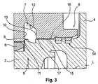
図2および図3の並置から、排気ターボ過給機1のシャフト2が、半径方向Rで外向きに油収集チャンバ7内へ延在する肩部9を有することが明らかになる。半径方向Rは、過給機軸Lと垂直な方向矢印として、図1および図3の両方に図示される。肩部9は、ロータジャーナルとも呼ばれる場合があり、その半径方向外向きに向けられた広がりの理由で、好適にはごく狭い設計であるギャップ11を、油収集チャンバ7のラジアル軸受側の第1の区切り壁10とともに区切る。
From the juxtaposition of FIGS. 2 and 3, it becomes clear that the
油収集チャンバ7は、油収集チャンバ7の第1の区切り壁10、上部壁12、および第2の区切り壁13などの外を向いたチャンバとして形成され、滑らかな表面を有するように機械加工される。これは、ギャップ11の前記狭い設計を達成するために好ましい。
The
特に図3から見ることができるように、上部壁12は第1の区切り壁10から第2の区切り壁13へと傾斜して下がり、すなわち、ピストンリング密封の側において、大きい直径領域から小さい直径領域へ、第1の区切り壁10から第2の区切り壁13へと続く。
As can be seen in particular from FIG. 3, the
図3は、長い設計が好ましく、シャフト2の外側周囲表面16と軸受筐体内側周囲表面17との間に形成されるピストンリング密封ギャップ15の提供も示す。前記ピストンリング密封ギャップ15は、油収集チャンバ7と軸受筐体端部領域8内に配設されるピストンリング密封14との間に配設される。
FIG. 3 also shows the provision of a piston
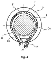
図4は、軸受筐体5、シャフト2、および油収集チャンバ7の概略的に高度に単純化された端面図を示し、滑らかな遷移Ueを介して、油Oeを、油収集チャンバ7内で上向きに、および前記油が漏斗形状出口19を介して流れて出るのを可能にするように引っ張る空気の流れLUが説明されるはずであり、ここで、軸受筐体5の油チャンバ18内に流れ案内要素20が配設される。流案内要素20は、図4の図式的な図から見ることができるように、ガセットまたは切頭円錐の様式で形成される。これは、シャフト2の高い回転速度と協働して、目標とする油の流れOeSを生み出す。
FIG. 4 shows a schematic and highly simplified end view of the bearing
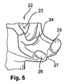
軸受筐体5内に油チャンバ18を形成することを可能にするために、図5および図6に図示される砂中子22が提供されてもよい。既知の設計と比較して短くなったタービン側軸受ブロック21(図2を参照のこと)を製造することを可能にするために、砂中子22は、表面23およびそれから軸方向に離間された表面24を有し、これらの表面は、完全に鋳造された状態で、図2に示される表面S1およびS2に対応する。
A
砂中子22は、切り欠き27を区切る突起25および26も有し、これは、完全に鋳造された状態で、図4に図示された流れ案内要素20を生み出す。
The
図7および図8は、その突起25および26の領域内の砂中子22、および、特に、油収集チャンバ7の形成29も可能にする機械加工28のモデルも示す。ここで、突起25および26は、外を向いた部分の下側、または油収集チャンバ7への中子の接続を形成する。
FIGS. 7 and 8 also show a model of
上記の開示を補足するために、図1〜図8において本発明の図式的な図示の参照が明示的に行われる。 To supplement the above disclosure, reference is made explicitly to the schematic illustrations of the present invention in FIGS.
1 排気ターボ過給機
2 シャフト
3 圧縮機ホイール
4 タービンホイール
5 軸受筐体
6 タービン側ラジアル軸受ブッシング
7 油収集チャンバ
8 軸受筐体端部領域
9 肩部/シャフト肩部/ロータジャーナル
10 第1の区切り壁
11 ギャップ
12 上部壁
13 第2の区切り壁
14 ピストンリング密封
15 ピストンリング密封ギャップ
16 シャフト2の外側周囲表面
17 軸受筐体内側周囲表面
18 軸受筐体5の油チャンバ
19 漏斗形状出口
20 流れ案内要素/ガセット
21 タービン側軸受ブロック
22 砂中子
23 表面
24 表面
25 突起
26 突起
27 凹部
28 機械加工のモデル
29 油収集チャンバの外を向いた部分
30 圧縮機側ラジアル軸受ブッシング
L 過給機軸
R 半径方向
LU 空気の流れ
Ue 滑らかな接線方向の遷移
Oe 油
OeS 油の流れ
S1 表面
S2 表面
1
DESCRIPTION OF SYMBOLS 3
Claims (5)
圧縮機ホイール(3)およびタービンホイール(4)がその上に配設されるシャフト(2)を有し、
タービン側ラジアル軸受ブッシング(6)を有し、かつ前記タービン側ラジアル軸受ブッシング(6)とタービン側軸受筐体端部領域(8)との間に配設された油収集チャンバ(7)を有する軸受筐体(5)を有し、
前記シャフト(2)は、半径方向(R)で外向きに前記油収集チャンバ(7)の中へ延在し、前記油収集チャンバ(7)のラジアル軸受側の第1の区切り壁(10)とともにギャップ(11)を区切る肩部(9)を有し、
前記油収集チャンバの前記第1の区切り壁(10)、上部壁(12)、および第2の区切り壁(13)が、機械加工されてなり、
前記油収集チャンバ(7)と前記軸受筐体端部領域(8)内に配設されたピストンリング密封(14)との間で、前記シャフト(2)の外側周囲表面(16)と軸受筐体内側周囲表面(17)との間にピストンリング密封ギャップ(15)が配設される、
排気ターボ過給機(1)。 An exhaust turbocharger (1),
A compressor wheel (3) and a turbine wheel (4) having a shaft (2) disposed thereon;
A turbine-side radial bearing bushing (6) and an oil collecting chamber (7) disposed between the turbine-side radial bearing bushing (6) and the turbine-side bearing housing end region (8). A bearing housing (5),
The shaft (2) extends radially outward (R) into the oil collection chamber (7), and a first partition wall (10) on the radial bearing side of the oil collection chamber (7). with have a shoulder (9) that separates the gap (11),
The first partition wall (10), the top wall (12), and the second partition wall (13) of the oil collecting chamber are machined;
Between the oil collecting chamber (7) and the piston ring seal (14) disposed in the bearing housing end region (8), the outer peripheral surface (16) of the shaft (2) and the bearing housing. A piston ring sealing gap (15) is disposed between the body inner peripheral surface (17),
Exhaust turbocharger (1).
Applications Claiming Priority (3)
| Application Number | Priority Date | Filing Date | Title |
|---|---|---|---|
| DE102010035282 | 2010-08-24 | ||
| DE102010035282.9 | 2010-08-24 | ||
| PCT/US2011/048219 WO2012027184A2 (en) | 2010-08-24 | 2011-08-18 | Exhaust-gas turbocharger |
Publications (2)
| Publication Number | Publication Date |
|---|---|
| JP2013536369A JP2013536369A (en) | 2013-09-19 |
| JP5933552B2 true JP5933552B2 (en) | 2016-06-15 |
Family
ID=45723989
Family Applications (1)
| Application Number | Title | Priority Date | Filing Date |
|---|---|---|---|
| JP2013526000A Expired - Fee Related JP5933552B2 (en) | 2010-08-24 | 2011-08-18 | Exhaust turbocharger |
Country Status (6)
| Country | Link |
|---|---|
| US (1) | US9222366B2 (en) |
| JP (1) | JP5933552B2 (en) |
| KR (1) | KR101779895B1 (en) |
| CN (1) | CN103026026B (en) |
| DE (1) | DE112011102807B4 (en) |
| WO (1) | WO2012027184A2 (en) |
Cited By (1)
| Publication number | Priority date | Publication date | Assignee | Title |
|---|---|---|---|---|
| JPH0723276B2 (en) | 1987-11-02 | 1995-03-15 | 三菱マテリアル株式会社 | Crystal growth equipment |
Families Citing this family (18)
| Publication number | Priority date | Publication date | Assignee | Title |
|---|---|---|---|---|
| US9163641B2 (en) | 2012-06-21 | 2015-10-20 | Electro-Motive Diesel, Inc. | Turbocharger support housing having improved drainage |
| CN104769232A (en) * | 2012-11-12 | 2015-07-08 | 博格华纳公司 | Bearing housing segment joining method for a turbocharger incorporating an electric motor |
| EP3859191B1 (en) | 2013-01-15 | 2024-05-01 | RTX Corporation | Fluid collection gutter for a geared turbine engine |
| EP2946131B1 (en) | 2013-01-15 | 2020-03-04 | United Technologies Corporation | Turbine engine |
| CN106795808B (en) * | 2014-11-17 | 2019-11-05 | 三菱重工发动机和增压器株式会社 | Turbo machine |
| US11066945B2 (en) | 2015-07-15 | 2021-07-20 | Raytheon Technologies Corporation | Fluid collection gutter for a geared turbine engine |
| WO2017014156A1 (en) * | 2015-07-22 | 2017-01-26 | 株式会社Ihi | Oil seal structure and supercharger |
| US9850857B2 (en) * | 2015-08-17 | 2017-12-26 | Electro-Motive Diesel, Inc. | Turbocharger blisk/shaft joint with heat isolation |
| US10641330B2 (en) * | 2016-03-01 | 2020-05-05 | Mitsubishi Heavy Industries Engine & Turbocharger, Ltd. | Bearing device and exhaust turbine supercharger |
| US10329954B2 (en) | 2016-04-14 | 2019-06-25 | Borgwarner Inc. | Flow strakes for turbocharger bearing housing oil core |
| AT519288B1 (en) * | 2016-10-21 | 2018-07-15 | Miba Gleitlager Austria Gmbh | bearing element |
| WO2018085213A1 (en) * | 2016-11-02 | 2018-05-11 | Borgwarner Inc. | Turbine having a multipart turbine housing |
| FR3062679B1 (en) * | 2017-02-07 | 2019-04-19 | Safran Aircraft Engines | VIROLE FOR REDUCING THE PRESSURE REDUCTION IN THE NEIGHBORHOOD OF THE UPPER JOINT OF A TURBOJET ENGINE BEARING ENCLOSURE |
| DE102017102420A1 (en) * | 2017-02-08 | 2018-08-09 | Abb Turbo Systems Ag | SLIDING STORAGE WITH HYDRODYNAMIC AXIAL SAFETY |
| KR101965062B1 (en) | 2017-06-30 | 2019-08-13 | 현대위아 주식회사 | Turbo Charger apparatus |
| US10900380B2 (en) | 2017-12-13 | 2021-01-26 | Borgwarner Inc. | Recirculation stall in compressor insert or backplate |
| CN110848019A (en) * | 2019-10-14 | 2020-02-28 | 中国北方发动机研究所(天津) | Altitude-variable self-adaptive turbocharger |
| WO2025252828A1 (en) * | 2024-06-05 | 2025-12-11 | Accelleron Switzerland Ltd. | Sealing arrangement, turbomachine, and method of operating a turbomachine |
Family Cites Families (18)
| Publication number | Priority date | Publication date | Assignee | Title |
|---|---|---|---|---|
| DE2843202A1 (en) * | 1978-10-04 | 1980-04-17 | Barmag Barmer Maschf | Turbocharger for IC engine - has perforated plate between inlet volute and turbine wheel for better low speed performance |
| US4240678A (en) * | 1979-02-22 | 1980-12-23 | Wallace Murray Corporation | Non-rotating fluid damped combination thrust and journal bearing |
| US4268229A (en) * | 1979-04-19 | 1981-05-19 | The Garrett Corporation | Turbocharger shaft seal arrangement |
| US4314705A (en) | 1979-05-23 | 1982-02-09 | Ishikawajima-Harima Jukogyo Kabushiki Kaisha | Oil seal device |
| JPS59154829U (en) * | 1983-03-31 | 1984-10-17 | 日産自動車株式会社 | Turbo gear oil leak prevention device |
| JPS6192724U (en) * | 1984-11-22 | 1986-06-16 | ||
| JPS61192522U (en) * | 1985-05-24 | 1986-11-29 | ||
| JPH036028U (en) * | 1989-06-07 | 1991-01-22 | ||
| JPH0565829A (en) * | 1991-09-05 | 1993-03-19 | Hitachi Ltd | Supercharger |
| US5308169A (en) * | 1992-11-20 | 1994-05-03 | Cummins Engine Company, Inc. | Bearing system for turbocharger |
| JPH1162600A (en) * | 1997-08-07 | 1999-03-05 | Tochigi Fuji Ind Co Ltd | Centrifugal fluid machine |
| WO2001069047A1 (en) | 2000-03-13 | 2001-09-20 | Alliedsignal Inc. | Ball bearing assembly for a turbocharger rotor |
| US6449950B1 (en) * | 2000-09-12 | 2002-09-17 | Honeywell International Inc. | Rotor and bearing system for electrically assisted turbocharger |
| JP4238610B2 (en) * | 2003-03-20 | 2009-03-18 | トヨタ自動車株式会社 | Turbocharger seal structure |
| US20070092387A1 (en) | 2005-10-21 | 2007-04-26 | Borgwarner Inc. | Oil discharge assembly for a turbocharger |
| JP2008208732A (en) * | 2007-02-23 | 2008-09-11 | Ihi Corp | Bearing housing structure of turbocharger |
| JP4816562B2 (en) | 2007-05-17 | 2011-11-16 | トヨタ自動車株式会社 | Oil seal structure |
| DE102007027869B4 (en) * | 2007-06-18 | 2010-04-29 | Continental Automotive Gmbh | Turbocharger with a turbocharger housing |
-
2011
- 2011-08-18 JP JP2013526000A patent/JP5933552B2/en not_active Expired - Fee Related
- 2011-08-18 DE DE112011102807.5T patent/DE112011102807B4/en not_active Expired - Fee Related
- 2011-08-18 US US13/816,516 patent/US9222366B2/en not_active Expired - Fee Related
- 2011-08-18 KR KR1020137006168A patent/KR101779895B1/en not_active Expired - Fee Related
- 2011-08-18 CN CN201180036708.7A patent/CN103026026B/en not_active Expired - Fee Related
- 2011-08-18 WO PCT/US2011/048219 patent/WO2012027184A2/en not_active Ceased
Cited By (1)
| Publication number | Priority date | Publication date | Assignee | Title |
|---|---|---|---|---|
| JPH0723276B2 (en) | 1987-11-02 | 1995-03-15 | 三菱マテリアル株式会社 | Crystal growth equipment |
Also Published As
| Publication number | Publication date |
|---|---|
| JP2013536369A (en) | 2013-09-19 |
| WO2012027184A2 (en) | 2012-03-01 |
| DE112011102807B4 (en) | 2023-02-16 |
| US9222366B2 (en) | 2015-12-29 |
| KR20130143011A (en) | 2013-12-30 |
| DE112011102807T5 (en) | 2013-05-29 |
| KR101779895B1 (en) | 2017-09-19 |
| US20130142679A1 (en) | 2013-06-06 |
| CN103026026A (en) | 2013-04-03 |
| WO2012027184A3 (en) | 2012-04-26 |
| CN103026026B (en) | 2016-05-11 |
Similar Documents
| Publication | Publication Date | Title |
|---|---|---|
| JP5933552B2 (en) | Exhaust turbocharger | |
| JP6368864B2 (en) | Turbocharger | |
| EP2236754A2 (en) | Steam turbine rotor blade and corresponding steam turbine | |
| CN204553354U (en) | Subtract the gas compressor of scroll and aeroengine | |
| JP5897009B2 (en) | Exhaust turbocharger bearing housing | |
| CN104747274A (en) | Turbocharger | |
| CN103670531A (en) | Impeller for a fluid machine and method for manufacturing a turbine for a fluid machine | |
| CN104271918A (en) | Oil flinger oil seal and associated turbocharger | |
| JP6504254B2 (en) | Bearing structure and supercharger | |
| CN202065055U (en) | Turbocharger | |
| CN103032347A (en) | Centrifugal compressor with isolation structure | |
| JP6640326B2 (en) | Method of manufacturing rotary machine, casing of rotary machine | |
| CN107816456A (en) | Supercharging device | |
| JP5818894B2 (en) | Exhaust turbocharger bearing housing | |
| KR101532439B1 (en) | Thrust bearing seal for exhaust gas turbo charger | |
| WO2017026292A1 (en) | Bearing structure and supercharger | |
| CN105604615A (en) | Exhaust turbocharger | |
| JP5797724B2 (en) | Exhaust gas turbocharger | |
| JP2019094899A (en) | Turbine and turbocharger | |
| CN104747240A (en) | Rotor system of small turbocharger | |
| CN205895595U (en) | Electric scroll compressor | |
| JP2019519717A (en) | Exhaust gas turbocharger bearing device and exhaust gas turbocharger | |
| CN104364531B (en) | Exhaust-driven turbo-charger exhaust-gas turbo charger | |
| CN113123857A (en) | Turbine box exhaust gas bypass device | |
| CN102905816A (en) | Stator and method for producing stator |
Legal Events
| Date | Code | Title | Description |
|---|---|---|---|
| A621 | Written request for application examination |
Free format text: JAPANESE INTERMEDIATE CODE: A621 Effective date: 20140226 |
|
| A977 | Report on retrieval |
Free format text: JAPANESE INTERMEDIATE CODE: A971007 Effective date: 20141120 |
|
| A131 | Notification of reasons for refusal |
Free format text: JAPANESE INTERMEDIATE CODE: A131 Effective date: 20141125 |
|
| A521 | Request for written amendment filed |
Free format text: JAPANESE INTERMEDIATE CODE: A523 Effective date: 20150220 |
|
| A131 | Notification of reasons for refusal |
Free format text: JAPANESE INTERMEDIATE CODE: A131 Effective date: 20150901 |
|
| A521 | Request for written amendment filed |
Free format text: JAPANESE INTERMEDIATE CODE: A523 Effective date: 20151201 |
|
| TRDD | Decision of grant or rejection written | ||
| A01 | Written decision to grant a patent or to grant a registration (utility model) |
Free format text: JAPANESE INTERMEDIATE CODE: A01 Effective date: 20160405 |
|
| A61 | First payment of annual fees (during grant procedure) |
Free format text: JAPANESE INTERMEDIATE CODE: A61 Effective date: 20160502 |
|
| R150 | Certificate of patent or registration of utility model |
Ref document number: 5933552 Country of ref document: JP Free format text: JAPANESE INTERMEDIATE CODE: R150 |
|
| R250 | Receipt of annual fees |
Free format text: JAPANESE INTERMEDIATE CODE: R250 |
|
| R250 | Receipt of annual fees |
Free format text: JAPANESE INTERMEDIATE CODE: R250 |
|
| R250 | Receipt of annual fees |
Free format text: JAPANESE INTERMEDIATE CODE: R250 |
|
| LAPS | Cancellation because of no payment of annual fees |