WO2017155037A1 - 鋳造装置 - Google Patents
鋳造装置 Download PDFInfo
- Publication number
- WO2017155037A1 WO2017155037A1 PCT/JP2017/009475 JP2017009475W WO2017155037A1 WO 2017155037 A1 WO2017155037 A1 WO 2017155037A1 JP 2017009475 W JP2017009475 W JP 2017009475W WO 2017155037 A1 WO2017155037 A1 WO 2017155037A1
- Authority
- WO
- WIPO (PCT)
- Prior art keywords
- cooling
- mold
- gas supply
- gas
- casting apparatus
- Prior art date
- Legal status (The legal status is an assumption and is not a legal conclusion. Google has not performed a legal analysis and makes no representation as to the accuracy of the status listed.)
- Ceased
Links
Images
Classifications
-
- B—PERFORMING OPERATIONS; TRANSPORTING
- B22—CASTING; POWDER METALLURGY
- B22D—CASTING OF METALS; CASTING OF OTHER SUBSTANCES BY THE SAME PROCESSES OR DEVICES
- B22D27/00—Treating the metal in the mould while it is molten or ductile ; Pressure or vacuum casting
- B22D27/04—Influencing the temperature of the metal, e.g. by heating or cooling the mould
-
- B—PERFORMING OPERATIONS; TRANSPORTING
- B22—CASTING; POWDER METALLURGY
- B22C—FOUNDRY MOULDING
- B22C9/00—Moulds or cores; Moulding processes
- B22C9/02—Sand moulds or like moulds for shaped castings
- B22C9/04—Use of lost patterns
-
- B—PERFORMING OPERATIONS; TRANSPORTING
- B22—CASTING; POWDER METALLURGY
- B22C—FOUNDRY MOULDING
- B22C9/00—Moulds or cores; Moulding processes
- B22C9/06—Permanent moulds for shaped castings
-
- B—PERFORMING OPERATIONS; TRANSPORTING
- B22—CASTING; POWDER METALLURGY
- B22C—FOUNDRY MOULDING
- B22C9/00—Moulds or cores; Moulding processes
- B22C9/06—Permanent moulds for shaped castings
- B22C9/065—Cooling or heating equipment for moulds
-
- B—PERFORMING OPERATIONS; TRANSPORTING
- B22—CASTING; POWDER METALLURGY
- B22C—FOUNDRY MOULDING
- B22C9/00—Moulds or cores; Moulding processes
- B22C9/10—Cores; Manufacture or installation of cores
-
- B—PERFORMING OPERATIONS; TRANSPORTING
- B22—CASTING; POWDER METALLURGY
- B22C—FOUNDRY MOULDING
- B22C9/00—Moulds or cores; Moulding processes
- B22C9/10—Cores; Manufacture or installation of cores
- B22C9/106—Vented or reinforced cores
-
- B—PERFORMING OPERATIONS; TRANSPORTING
- B22—CASTING; POWDER METALLURGY
- B22C—FOUNDRY MOULDING
- B22C9/00—Moulds or cores; Moulding processes
- B22C9/22—Moulds for peculiarly-shaped castings
-
- B—PERFORMING OPERATIONS; TRANSPORTING
- B22—CASTING; POWDER METALLURGY
- B22C—FOUNDRY MOULDING
- B22C9/00—Moulds or cores; Moulding processes
- B22C9/22—Moulds for peculiarly-shaped castings
- B22C9/24—Moulds for peculiarly-shaped castings for hollow articles
-
- B—PERFORMING OPERATIONS; TRANSPORTING
- B22—CASTING; POWDER METALLURGY
- B22D—CASTING OF METALS; CASTING OF OTHER SUBSTANCES BY THE SAME PROCESSES OR DEVICES
- B22D27/00—Treating the metal in the mould while it is molten or ductile ; Pressure or vacuum casting
- B22D27/003—Treating the metal in the mould while it is molten or ductile ; Pressure or vacuum casting by using inert gases
-
- B—PERFORMING OPERATIONS; TRANSPORTING
- B22—CASTING; POWDER METALLURGY
- B22D—CASTING OF METALS; CASTING OF OTHER SUBSTANCES BY THE SAME PROCESSES OR DEVICES
- B22D30/00—Cooling castings, not restricted to casting processes covered by a single main group
Definitions
- the present invention relates to a casting apparatus for obtaining a cast product by directional solidification, and more particularly to a casting apparatus having a high cooling capacity for performing directional solidification.
- This casting apparatus enables directional solidification by cooling sequentially from one end of the poured mold to the other end, usually from the lower end to the upper end.
- This casting apparatus includes a heating chamber and a cooling chamber adjacent to each other, and the mold poured in the heating chamber moves from its lower end to the cooling chamber at a moderate speed.
- solidification proceeds while maintaining a large temperature gradient at the solidification interface of the molten metal while moving the mold to the cooling chamber at a moderate speed.
- a cooling gas composed of an inert gas is blown onto a mold in a cooling chamber.
- An object of the present invention is to stably realize a high cooling capacity in a casting apparatus that blows cooling gas onto a mold in a cooling chamber.
- the casting apparatus of the present invention includes a heating chamber in which molten metal is poured into a mold, and a cooling chamber that is provided adjacent to the heating chamber and performs directional solidification while moving the mold into which molten metal is poured.
- the cooling chamber according to the present invention includes a gas cooling unit having one or a plurality of gas supply nozzles for blowing a cooling gas toward the mold, and each gas supply nozzle discharges a cooling gas corresponding to the movement of the mold. The position of the end is adjusted.
- each gas supply nozzle can maintain the distance between the discharge end and the mold constant by adjusting the position of the discharge end of the cooling gas corresponding to the movement of the mold. A high cooling capacity by gas blowing can be stably obtained.
- the distance can be adjusted to an optimum distance, so that a high cooling capacity by blowing cooling gas can be obtained more stably.
- the gas supply nozzle in the present invention can adjust the position of the discharge end by moving, and as one form thereof, the position of the discharge end can be adjusted by moving the gas supply nozzle back and forth.
- the position of the discharge end can be adjusted by expanding and contracting the gas supply nozzle at a fixed position.
- the gas supply nozzle can have a slit-like nozzle opening extending in the horizontal direction.
- the gas supply nozzle can have its discharge end facing downward.
- the cooling chamber in the present invention preferably includes a radiation cooling unit that cools the mold by radiation.
- the radiant cooling section in the present invention is preferably arranged in series in the vertical direction with the gas cooling section below the gas cooling section provided immediately below the heat shield that separates the heating chamber and the cooling chamber.
- This radiant cooling section is preferably a cylindrical water cooling jacket that surrounds the mold and circulates cooling water below the gas cooling section.
- one or a plurality of gas supply nozzles corresponding to the respective molds are provided.
- the edge position can be adjusted.
- the position of the discharge end can be adjusted by rotating the gas supply nozzle or nozzles in the horizontal direction.
- each gas supply nozzle can adjust the position of the discharge end of the cooling gas corresponding to the movement of the mold, so that the high cooling capacity of the mold by blowing the cooling gas can be stabilized. Obtainable.
- the casting apparatus 1 manufactures parts such as a moving blade and a stationary blade for a gas turbine that require mechanical strength at a high temperature by precision casting to which directional solidification is applied.
- the casting apparatus 1 is made especially for the purpose of maximizing the cooling ability of the mold by the cooling gas.
- the casting apparatus 1 includes a vacuum chamber 2 in which an internal space is maintained in a reduced pressure state, a pouring chamber 3 disposed relatively above the inside of the vacuum chamber 2, and a vacuum chamber 2.
- a heating chamber 4 provided below the pouring chamber 3 inside, and a cooling chamber 5 provided below the heating chamber 4 inside the vacuum chamber 2 are provided.
- a heat shield 6 is provided at the boundary between the pouring chamber 3 and the heating chamber 4, and a heat shield 7 is provided at the boundary between the heating chamber 4 and the cooling chamber 5.
- FIG. 2 shows a state in which the mold M is accommodated in the casting apparatus 1.
- inside the cooling chamber 5 there are provided a drive rod 8 that moves the mold M up and down, and a cooling table 9 that is provided on the top of the drive rod 8 and supports the mold M from below and cools it. ing.
- the mold M is made of a refractory material, and as shown in FIG. 2, a cavity that is a space corresponding to the outer shape of a moving blade or a stationary blade to be cast is formed inside.
- the mold M has the smallest width-wise dimension (hereinafter, thickness) at the lower end, and the largest thickness at the flange F formed in a portion near the upper end.
- the cavity of the mold M has an upper opening MA at the upper end and a lower opening MB at the lower end, and penetrates in the vertical direction.
- the molten alloy A can be filled into the cavity of the mold M from the upper opening MA.
- the lower opening MB is closed from below by the cooling table 9, and the bottom wall of the mold M is configured by the cooling table 9.
- the interior of the vacuum chamber 2 is maintained in a vacuum state during casting by the operation of a vacuum pump (not shown).
- the pouring chamber 3 pours molten alloy A stored in a pouring ladle (not shown) into the mold M through the pouring nozzle 11 during pouring.
- the pouring nozzle 11 is supported by a heat shield 6 that forms a boundary between the pouring chamber 3 and the heating chamber 4.
- An unillustrated pouring ladle is introduced into the pouring chamber 3 from the outside before the vacuum chamber 2 is evacuated, and then the vacuum chamber 2 is depressurized to a vacuum before being melted from the pouring ladle.
- Pour alloy A is introduced into the pouring chamber 3 from the outside before the vacuum chamber 2 is evacuated, and then the vacuum chamber 2 is depressurized to a vacuum before being melted from the pouring ladle.
- the heating chamber 4 holds the mold M into which the molten alloy A is poured at a temperature higher than the melting point of the alloy A during casting.
- the heating chamber 4 is provided with a heater 12 as shown in FIGS.
- the heater 12 is provided in a cylindrical shape along the circumferential direction of the inner wall surface 4A so as to surround the inner space.
- the heat shield 7 separates the heating chamber 4 and the cooling chamber 5 and suppresses heat transfer between them.
- the heat shield 7 is provided at the boundary between the heating chamber 4 and the cooling chamber 5 so as to protrude in the horizontal direction from the inner wall surface 5 ⁇ / b> A of the cooling chamber 5 toward the center thereof.
- the heat shield 7 is formed with a mold passage 7A communicating the heating chamber 4 and the cooling chamber 5 at the center thereof.
- the opening diameter of the mold passage 7A is the maximum thickness of the mold M. It is set larger than the flange F having.
- the mold M is disposed at the center of the vacuum chamber 2 and can be moved in the vertical direction between the heating chamber 4 and the cooling chamber 5 through the mold passage 7A of the heat shield 7.
- the cooling chamber 5 is an area for solidifying the poured molten alloy A.
- the cooling chamber 5 is maintained at a temperature lower than the melting point of the alloy A poured into the mold M, and the molten alloy A is A cooling mechanism 20 for forcibly cooling is provided.
- the mold M that has received the molten alloy A in the heating chamber 4 moves to the cooling chamber 5, and upstream and downstream are defined based on the direction in which the mold M moves.
- the cooling mechanism 20 includes a gas cooling unit 21 and a radiant cooling unit 25.
- the gas cooling unit 21 includes a plurality of gas supply nozzles 22 that eject a cooling gas CG (FIG. 2) supplied from a gas supply source (not shown), and an actuator 23 that moves the gas supply nozzle 22 back and forth. .
- the position of the discharge end 221 is adjusted by moving the gas supply nozzle 22 in response to the movement of the mold M.
- the gas supply nozzle 22 is provided immediately below the heat shield 7 in the vertical direction, and in the horizontal direction, as shown in FIG. 2, the gas supply nozzle 22 surrounds the mold M from the periphery.
- the mold M can be uniformly cooled in the horizontal direction.
- the gas supply nozzle 22 blows the cooling gas CG toward the mold M from the discharge end 221 that is the tip facing the mold M.
- the cooling gas CG sprayed from the gas supply nozzle 22 toward the mold M is preferably an inert gas such as argon (Ar) or helium (He) in order to suppress oxidation of the alloy A.
- the temperature of the cooling gas CG is sufficient if it is about room temperature. However, when it is desired to increase the solidification rate, the cooling gas CG having a temperature lower than the room temperature can be used.
- the actuator 23 advances and retracts the gas supply nozzle 22 in order to keep the distance between the discharge end 221 of the gas supply nozzle 22 and the mold M constant while avoiding interference between the gas supply nozzle 22 and the mold M. That is, the gas supply nozzle 22 is advanced and retracted according to the thickness of the mold M. The gas supply nozzle 22 is advanced when the mold M is thin, and the gas supply nozzle 22 when the mold M is thick. Treatment.
- the actuator 23 is provided corresponding to each of the plurality of gas supply nozzles 22, and each of the gas supply nozzles 22 is independently advanced and retracted. Therefore, even if the mold M has an irregular shape, the distance from each gas supply nozzle 22 to the mold M can be maintained constant or adjusted to an optimum distance.
- the radiant cooling unit 25 radiatively cools the mold M.
- radiation is a phenomenon in which energy is transferred from a high-temperature object to a low-temperature object.
- the high-temperature object is the mold M
- the low-temperature object is the radiation cooling unit 25.
- the radiant cooling unit 25 circulates a cooling medium, for example, cooling water CW, through a passage formed of, for example, a cylindrical water cooling jacket 26 made of copper, copper alloy, aluminum, aluminum alloy or the like having high thermal conductivity. It has the structure to do.
- the radiant cooling unit 25 surrounds the mold M from its periphery, so that the high-temperature mold M passing through the hollow portion is radiatively cooled.
- the radiant cooling unit 25 is provided immediately below the gas supply nozzle 22 of the gas cooling unit 21, and the gas supply nozzle 22 and the radiant cooling unit 25 are arranged in series in the vertical direction.
- the drive rod 8 moves the mold M up and down via the cooling table 9. As shown in FIGS. 1 and 2, the drive rod 8 is provided through the bottom wall 5 ⁇ / b> B of the cooling chamber 5. To do.
- the cooling table 9 supports the mold M from below while closing the lower opening MB of the mold M, and particularly cools the alloy A inside the mold M through the lower opening MB.
- the discharge end 221 of the gas supply nozzle 22 stands by at an advanced position closest to the central axis of the casting apparatus 1.
- the cooling gas CG may be discharged from the gas supply nozzle 22 or the cooling water CW may be circulated through the water cooling jacket 26.
- the cooling step ends. Thereafter, the mold M is taken out from the cooling chamber 5 and then released from the mold to obtain a directionally solidified cast product.
- the casting apparatus 1 cools by blowing the cooling gas CG from the gas supply nozzle 22 as the mold M descends in the cooling chamber 5, and radiative cooling by the radiant cooling unit 25, thereby lowering the lower end of the mold M. Cooling is performed from the top to the top. Therefore, according to the present embodiment, it is possible to perform directional solidification while improving the temperature gradient and the solidification rate by increasing the cooling rate of the mold M. Thereby, it is possible to manufacture a cast product having increased mechanical strength while suppressing casting defects.
- the present embodiment uses a gas supply nozzle 22 that can move forward and backward, and can cool while maintaining a constant distance between the discharge end 221 of the gas supply nozzle 22 and the mold M.
- High cooling performance can be maintained.
- the supply amount of the cooling gas CG can be increased / decreased instead of the advance / retreat of the gas supply nozzle 22, but in this embodiment, a larger amount of the cooling gas CG is required. Since the supply amount of the gas CG can be kept to a certain minimum, the manufacturing cost of the cast product can be kept low.
- the mechanism for moving the gas supply nozzle 22 back and forth has the advantage of being simple. However, it is not excluded to increase or decrease the supply amount of the cooling gas CG in addition to the present invention.
- the casting apparatus 1 can exhibit the respective cooling performance without hindering the cooling function of each other. it can.
- the radiation cooling unit 25 also performs radiation cooling for the gas supply nozzle 22 and the discharged cooling gas CG, the cooling of the mold M by the gas cooling unit 21 is maximized.
- the cooling mechanism 20 is arranged from the top in the order of the gas cooling unit 21 and the radiation cooling unit 25, and the descending mold M is cooled by the cooling gas CG blown from the gas supply nozzle 22, and then the radiation cooling unit. 25 for radiative cooling.
- the temperature of the mold M itself is higher than the temperature in the region immediately after leaving the heating chamber 4. Since CG can be supplied, the cooling performance by the gas cooling unit 21 can be maximized.
- a plurality of molds M (M1, M2, M3, M4) arranged around a predetermined region are moved from the heating chamber 4 and supplied to the plurality of molds M.
- a drive rod 8 for moving a plurality of molds M (M1, M2, M3, M4) from a heating chamber 4 and a plurality of molds M (M1, M1, M2) from the inside of a predetermined region.
- M2, M3, M4) are cooled by a cooling gas, and a plurality of molds M (M1, M2, M3, M4) are blown from a gas supply nozzle 22 from outside a predetermined region.
- the present invention can also be suitably applied to a casting apparatus 1 that includes a gas cooling unit 21 that cools.
- the gas supply nozzle 22 can be moved back and forth as shown in FIG. 5A, but by rotating the gas supply nozzle 22 as shown in FIG. The position of the discharge end can also be moved to a position where it does not interfere with the mold M (M1, M2, M3, M4).
- the gas cooling unit 21 includes a plurality of independent gas supply nozzles 22, but as illustrated in FIG. 6A, includes a slit-like nozzle opening 222 extending in the width direction, that is, the horizontal direction.
- a gas supply nozzle 22 can be used.
- the gas supply nozzle 22 has a discharge end 221 formed in a V shape, and a pair of gas supply nozzles 22 are used with the discharge ends 221 facing the mold M as shown in FIG. .
- the gas supply nozzle 22 is also advanced and retracted by the actuator 23.
- the gas supply nozzle 22 having the slit-like nozzle opening 222 is used, the discharge flow rate of the cooling gas CG becomes uniform, so that the surface of the mold M can be cooled uniformly.
- the gas supply nozzle 22 mentioned above shows the example which discharges the cooling gas CG in a horizontal direction
- this invention is not limited to this,
- tip is heated. It is preferable to use a gas supply nozzle 22 that faces downward from the chamber 4. By doing so, it becomes possible to reduce the flow rate of the cooling gas CG that flows unnecessarily into the heating chamber 4, so that the output of the heater 12 can be reduced.
- the gas cooling unit 21 described above can maintain the distance from the mold M constant or optimally adjusted by the gas supply nozzle 22 moving forward and backward, but the present invention is not limited to this.
- the gas supply nozzle 22 expands and contracts at a fixed position, so that the distance between the discharge end 221 that is the front end for discharging the cooling gas CG and the mold M is kept constant or optimal. You can adjust the distance.
- the area occupied by the gas supply nozzle 22 can be made narrower than providing the actuator 23 for the gas supply nozzle 22.
- the gas supply nozzle 22 has a short S, an intermediate M, and a long L, but in reality, one gas supply nozzle 22 expands and contracts at a fixed position.
- S, M, and L are shown here, it is preferable to use a gas supply nozzle 22 that can be expanded and contracted steplessly.
- each of the gas supply nozzles 22 is moved forward and backward.
- the movement of the gas supply nozzle 22 in the present invention is not limited to this, and for example, in a group of a plurality of gas supply nozzles 22. It can be translated horizontally.
- the gas supply nozzles 22A, 22B, 22C, 22D, 22E, and 22F are grouped in the left direction in the figure.
- the gas supply nozzles 22G and 22H can be translated as a group in the downward direction in the figure.
- each of the plurality of gas supply nozzles 22 can be rotated in the horizontal direction. Specifically, as shown in FIGS.
- the region surrounded by the gas supply nozzles 22 to 22H can be widened or narrowed. it can.
- the movement of the gas supply nozzle 22 is not limited to that illustrated in FIG. 8.
- the plurality of gas supply nozzles 22 to 22H are translated in units of groups.
- the plurality of gas supply nozzles 22 can be rotated and moved in units of groups.
- the movement may be performed not only in the horizontal direction but also in the vertical direction.
- a rotation axis is set in the horizontal direction, and the gas supply nozzle 22 is swung around the rotation axis. It can also be moved.
- the method for controlling the movement of the gas supply nozzle 22 is arbitrary.
- data on the size and shape of the mold M used for casting is stored, and the gas supply nozzle is based on the data.
- 22 advance / retreat positions can be adjusted.
- a distance measuring sensor that measures the distance from the discharge end 221 of the gas supply nozzle 22 to the surface of the mold M is provided, and the gas supply nozzle is based on the distance to the surface of the mold M measured by the distance measuring sensor. 22 advance / retreat positions can be adjusted.
Landscapes
- Engineering & Computer Science (AREA)
- Mechanical Engineering (AREA)
- Molds, Cores, And Manufacturing Methods Thereof (AREA)
Abstract
本発明の鋳造装置1は、それぞれのガス供給ノズル22が、鋳型Mの移動に対応して、冷却ガスCGの吐出端221の位置を調整できるので、冷却ガスCGの吹き付けによる鋳型Mの高い冷却能力を安定して得ることができる。吐出端221の位置を調整するには、ガス供給ノズル22を進退移動させる、あるいは、ガス供給ノズル22を伸縮させればよい。また、冷却室5は、放射により鋳型Mを冷却する放射冷却部25を備えることができ、放射冷却部25は、加熱室4と冷却室5を区切る遮熱体7の直下に設けられるガス供給ノズル22よりも下方に配置される。
Description
本発明は、方向性凝固により鋳造品を得る鋳造装置に関し、特に、方向性凝固をするための冷却能力の高い鋳造装置に関する。
例えば、タービン用の翼、その他の部品は、方向性凝固を適用した精密鋳造により、その結晶構造を柱状結晶又は単結晶とすることによりクリープ変形の抑制、及び、疲労強度の向上を図っている。この鋳造装置は、注湯された鋳型の一端部から他端部、通常は下端部から上端部に向けて順次冷却することにより、方向性凝固を可能としている。この鋳造装置は、互いに隣接する加熱室と冷却室を備え、加熱室で注湯された鋳型は、緩やかな速度でその下端部から冷却室に移動する。
このように、方向性凝固を達成するためには鋳型を冷却室へ緩やかな速度で移動させつつ、溶湯の凝固界面における温度勾配が大きい状態を維持しながら凝固を進める。鋳造欠陥を抑え、健全な柱状結晶又は単結晶を得るには、温度勾配を大きくして凝固速度(又は冷却速度)を速くすることが重要である。
凝固速度を速くする手段として、例えば特許文献1に記載されるように、冷却室において不活性ガスからなる冷却ガスを鋳型へ吹き付けることが行われる。
凝固速度を速くする手段として、例えば特許文献1に記載されるように、冷却室において不活性ガスからなる冷却ガスを鋳型へ吹き付けることが行われる。
本発明は、冷却室で鋳型に冷却ガスを吹き付ける鋳造装置において、高い冷却能力を安定して実現することを目的とする。
本発明の鋳造装置は、鋳型に溶融金属が注がれる加熱室と、加熱室に隣接して設けられ、溶融金属が注がれた鋳型を移動させながら方向性凝固を行なう冷却室と、を備える。
本発明における冷却室は、鋳型に向けて冷却ガスを吹き付ける、単数又は複数のガス供給ノズルを有するガス冷却部を備え、それぞれのガス供給ノズルは、鋳型の移動に対応して、冷却ガスの吐出端の位置が調整される、ことを特徴とする。
本発明の鋳造装置は、それぞれのガス供給ノズルが、鋳型の移動に対応して、冷却ガスの吐出端の位置を調整することで、吐出端と鋳型との距離を一定に維持できるので、冷却ガスの吹き付けによる高い冷却能力を安定して得ることができる。または、吐出端と鋳型との距離を一定か否かにかかわらず、最適な距離に調整できるので、冷却ガスの吹き付けによる高い冷却能力をさらに安定して得ることができる。
本発明における冷却室は、鋳型に向けて冷却ガスを吹き付ける、単数又は複数のガス供給ノズルを有するガス冷却部を備え、それぞれのガス供給ノズルは、鋳型の移動に対応して、冷却ガスの吐出端の位置が調整される、ことを特徴とする。
本発明の鋳造装置は、それぞれのガス供給ノズルが、鋳型の移動に対応して、冷却ガスの吐出端の位置を調整することで、吐出端と鋳型との距離を一定に維持できるので、冷却ガスの吹き付けによる高い冷却能力を安定して得ることができる。または、吐出端と鋳型との距離を一定か否かにかかわらず、最適な距離に調整できるので、冷却ガスの吹き付けによる高い冷却能力をさらに安定して得ることができる。
本発明におけるガス供給ノズルは、移動することにより、吐出端の位置を調整することができ、その一形態として、ガス供給ノズルを進退移動することにより、吐出端の位置を調整できる。また、本発明は、ガス供給ノズルを定位置において伸縮することにより、吐出端の位置を調整できる。
本発明において、複数のガス供給ノズルを、鋳型を取り囲むように、水平方向に放射状に設けることが好ましい。
本発明において、ガス供給ノズルを、水平方向に延びるスリット状のノズル開口を有するものにできる。
本発明において、ガス供給ノズルは、その吐出端を下向きにできる。
本発明において、ガス供給ノズルを、水平方向に延びるスリット状のノズル開口を有するものにできる。
本発明において、ガス供給ノズルは、その吐出端を下向きにできる。
本発明における冷却室は、放射により鋳型を冷却する放射冷却部を備えることが好ましい。
本発明における放射冷却部は、加熱室と冷却室を区切る遮熱体の直下に設けられるガス冷却部よりも下方において、ガス冷却部と鉛直方向に直列に配列されることが好ましい。
この放射冷却部は、ガス冷却部の下方において鋳型の周囲を取り囲み冷却水が循環する、円筒状の水冷ジャケットであることが好ましい。
本発明における放射冷却部は、加熱室と冷却室を区切る遮熱体の直下に設けられるガス冷却部よりも下方において、ガス冷却部と鉛直方向に直列に配列されることが好ましい。
この放射冷却部は、ガス冷却部の下方において鋳型の周囲を取り囲み冷却水が循環する、円筒状の水冷ジャケットであることが好ましい。
本発明において、複数の鋳型で同時に鋳造を行う場合には、それぞれの鋳型に対応する単数又は複数のガス供給ノズルを備えることになるが、鋳型の移動に対応して、このガス供給ノズルの吐出端の位置を調整できる。
この鋳造装置において、単数又は複数のガス供給ノズルを、水平方向に回転することで、吐出端の位置を調整できる。
この鋳造装置において、単数又は複数のガス供給ノズルを、水平方向に回転することで、吐出端の位置を調整できる。
本発明の鋳造装置によれば、それぞれのガス供給ノズルが、鋳型の移動に対応して、冷却ガスの吐出端の位置を調整できるので、冷却ガスの吹き付けによる鋳型の高い冷却能力を安定して得ることができる。
以下、添付図面を参照しながら、本発明の実施形態に係る鋳造装置1について説明する。
鋳造装置1は、高い温度で機械的強度が要求される、例えば、ガスタービン用の動翼、静翼等の部品を方向性凝固が適用される精密鋳造によって製造する。鋳造装置1は、特に、冷却ガスによる鋳型の冷却能力を最大限に発揮することを目的としてなされたものである。
鋳造装置1は、高い温度で機械的強度が要求される、例えば、ガスタービン用の動翼、静翼等の部品を方向性凝固が適用される精密鋳造によって製造する。鋳造装置1は、特に、冷却ガスによる鋳型の冷却能力を最大限に発揮することを目的としてなされたものである。
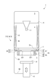
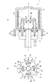
鋳造装置1は、図1に示すように、内部空間が減圧状態に保持された真空室2と、真空室2の内部の相対的に上方に配置される注湯室3と、真空室2の内部において注湯室3よりも下方に設けられる加熱室4と、真空室2の内部において加熱室4の下方に設けられる冷却室5と、を備えている。真空室2の内部において、注湯室3と加熱室4の境界部分には遮熱体6が設けられ、加熱室4と冷却室5の境界部分には遮熱体7が設けられている。
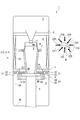
また図2は、鋳造装置1の内部に鋳型Mを収容した様子を示している。図2に示すように、冷却室5の内部には、鋳型Mを昇降させる駆動ロッド8と、駆動ロッド8の頂部に設けられ、鋳型Mを下方から支持するとともに冷却する冷却テーブル9が設けられている。
また図2は、鋳造装置1の内部に鋳型Mを収容した様子を示している。図2に示すように、冷却室5の内部には、鋳型Mを昇降させる駆動ロッド8と、駆動ロッド8の頂部に設けられ、鋳型Mを下方から支持するとともに冷却する冷却テーブル9が設けられている。
鋳型Mは、耐火材料よりなり、図2に示すように、鋳造しようとする動翼又は静翼等の外形に対応する空間であるキャビティが内部に形成されている。鋳型Mは、下端の幅方向の寸法(以下、太さ)が最も小さく、上端に近い部分に形成されるフランジFにおける太さが最も大きい。
鋳型Mのキャビティは、上端に上部開口MAが、また、下端に下部開口MBが設けられており、上下方向に貫通している。そして、上部開口MAより溶融状態の合金Aが鋳型Mのキャビティへ充填可能とされている。また、下部開口MBは冷却テーブル9によって下方から閉塞されるとともに、この冷却テーブル9によって鋳型Mの底壁が構成される。
鋳型Mのキャビティは、上端に上部開口MAが、また、下端に下部開口MBが設けられており、上下方向に貫通している。そして、上部開口MAより溶融状態の合金Aが鋳型Mのキャビティへ充填可能とされている。また、下部開口MBは冷却テーブル9によって下方から閉塞されるとともに、この冷却テーブル9によって鋳型Mの底壁が構成される。
図1及び図2において、真空室2は、図示を省略する真空ポンプの動作により、鋳造時には内部の空間が概ね真空状態に維持される。
注湯室3は、注湯時に、図示を省略する注湯取鍋に溜められた溶融状態の合金Aを、注湯ノズル11を介して鋳型Mに注ぐ。注湯ノズル11は、注湯室3と加熱室4の境界をなす遮熱体6に支持されている。図示を省略する注湯取鍋は、真空室2を真空にする前に外部から注湯室3に導入され、その後、真空室2を真空に減圧してから、注湯取鍋から溶融状態の合金Aを注湯する。
注湯室3は、注湯時に、図示を省略する注湯取鍋に溜められた溶融状態の合金Aを、注湯ノズル11を介して鋳型Mに注ぐ。注湯ノズル11は、注湯室3と加熱室4の境界をなす遮熱体6に支持されている。図示を省略する注湯取鍋は、真空室2を真空にする前に外部から注湯室3に導入され、その後、真空室2を真空に減圧してから、注湯取鍋から溶融状態の合金Aを注湯する。
加熱室4は、鋳造の際に、溶融状態の合金Aが注がれた鋳型Mを、当該合金Aの融点よりも高い温度に保持する。そのために、加熱室4は、図1及び図2に示すように、加熱ヒータ12が設けられている。加熱ヒータ12は、その内部空間を取り囲むように、その内壁面4Aの周方向に沿って円筒状に設けられている。
遮熱体7は、加熱室4と冷却室5との間を区切り、両者間の熱伝達を抑える。
遮熱体7は、図1及び図2に示すように、加熱室4と冷却室5の境界において、冷却室5の内壁面5Aからその中心に向かって水平方向に突出して設けられている。また、この遮熱体7には、その中央部に加熱室4と冷却室5とを連通する鋳型通路7Aが形成されており、この鋳型通路7Aの開口径は、鋳型Mの最大の太さを有するフランジFよりも大きく設定されている。鋳型Mは、真空室2の中央部に配置されるものであり、遮熱体7の鋳型通路7Aを通じて、加熱室4と冷却室5との間を上下方向に移動可能とされている。
遮熱体7は、図1及び図2に示すように、加熱室4と冷却室5の境界において、冷却室5の内壁面5Aからその中心に向かって水平方向に突出して設けられている。また、この遮熱体7には、その中央部に加熱室4と冷却室5とを連通する鋳型通路7Aが形成されており、この鋳型通路7Aの開口径は、鋳型Mの最大の太さを有するフランジFよりも大きく設定されている。鋳型Mは、真空室2の中央部に配置されるものであり、遮熱体7の鋳型通路7Aを通じて、加熱室4と冷却室5との間を上下方向に移動可能とされている。
次に冷却室5について説明する。
冷却室5は、注がれた溶融状態の合金Aを凝固させる領域であり、鋳型Mの内部へ注がれた合金Aの融点よりも低い温度に保持されるとともに、溶融状態の合金Aを強制的に冷却する冷却機構20を備えている。
加熱室4で溶融状態の合金Aを受け取った鋳型Mは冷却室5に移動するが、この鋳型Mが移動する向きを基準に上流と下流を定義する。
冷却室5は、注がれた溶融状態の合金Aを凝固させる領域であり、鋳型Mの内部へ注がれた合金Aの融点よりも低い温度に保持されるとともに、溶融状態の合金Aを強制的に冷却する冷却機構20を備えている。
加熱室4で溶融状態の合金Aを受け取った鋳型Mは冷却室5に移動するが、この鋳型Mが移動する向きを基準に上流と下流を定義する。
冷却機構20は、図1及び図2に示すように、ガス冷却部21と、放射冷却部25と、を備えている。
ガス冷却部21は、図示を省略するガス供給源から供給される冷却ガスCG(図2)を噴出する複数のガス供給ノズル22と、ガス供給ノズル22を進退させるアクチュエータ23と、を備えている。ガス供給ノズル22は、鋳型Mが移動するのに対応して、移動することによりその吐出端221の位置が調整される。
ガス供給ノズル22は、鉛直方向については、図1に示すように、遮熱体7の直下に設けられるとともに、水平方向については、図2に示すように、鋳型Mを周囲から取り囲むように、水平方向に放射状に設けられており、鋳型Mを水平方向に均一に冷却できる。ガス供給ノズル22は、鋳型Mに対向する先端である吐出端221から冷却ガスCGを鋳型Mに向けて吹き付ける。ガス供給ノズル22から鋳型Mに向けて吹き付けられる冷却ガスCGは、合金Aの酸化を抑制するために、アルゴン(Ar)、ヘリウム(He)などの不活性ガスを用いることが好ましい。また、冷却ガスCGの温度は、常温程度であれば十分であるが、特に凝固速度を速くしたいときには、常温よりも低い温度の冷却ガスCGを用いることができる。
ガス冷却部21は、図示を省略するガス供給源から供給される冷却ガスCG(図2)を噴出する複数のガス供給ノズル22と、ガス供給ノズル22を進退させるアクチュエータ23と、を備えている。ガス供給ノズル22は、鋳型Mが移動するのに対応して、移動することによりその吐出端221の位置が調整される。
ガス供給ノズル22は、鉛直方向については、図1に示すように、遮熱体7の直下に設けられるとともに、水平方向については、図2に示すように、鋳型Mを周囲から取り囲むように、水平方向に放射状に設けられており、鋳型Mを水平方向に均一に冷却できる。ガス供給ノズル22は、鋳型Mに対向する先端である吐出端221から冷却ガスCGを鋳型Mに向けて吹き付ける。ガス供給ノズル22から鋳型Mに向けて吹き付けられる冷却ガスCGは、合金Aの酸化を抑制するために、アルゴン(Ar)、ヘリウム(He)などの不活性ガスを用いることが好ましい。また、冷却ガスCGの温度は、常温程度であれば十分であるが、特に凝固速度を速くしたいときには、常温よりも低い温度の冷却ガスCGを用いることができる。
アクチュエータ23は、ガス供給ノズル22と鋳型Mとの干渉を避けつつ、ガス供給ノズル22の吐出端221と鋳型Mとの距離を一定に保つために、ガス供給ノズル22を進退させる。つまり、ガス供給ノズル22の進退は、鋳型Mの太さに応じてなされるものであり、鋳型Mが細い部分では、ガス供給ノズル22を前進させ、鋳型Mが太い部分では、ガス供給ノズル22を後退させる。アクチュエータ23は、複数のガス供給ノズル22のそれぞれに対応して設けられており、ガス供給ノズル22のそれぞれは、独立して進退動作がなされる。したがって、平面形状が異形をなす鋳型Mであっても、それぞれのガス供給ノズル22から鋳型Mまでの距離を一定に維持し、または、最適な距離に調整できる。
次に、放射冷却部25は、鋳型Mを放射冷却する。ここで、放射とは、高温の物体から低温の物体にエネルギが伝達される現象であり、鋳造装置1の場合には、高温の物体が鋳型Mであり、低温の物体が放射冷却部25である。
放射冷却部25は、熱伝導率の高い銅、銅合金、アルミニウム、アルミニウム合金などで形成された、例えば円筒状の水冷ジャケット26の内部に形成された通路を冷却媒体、例えば冷却水CWが循環する構造を有している。放射冷却部25は、鋳型Mをその周囲から取り囲むことで、中空部分を通過する高温の鋳型Mが放射冷却される。
放射冷却部25は、ガス冷却部21のガス供給ノズル22の直下に隣接して設けられており、ガス供給ノズル22と放射冷却部25は、鉛直方向に直列に配列されている。
放射冷却部25は、熱伝導率の高い銅、銅合金、アルミニウム、アルミニウム合金などで形成された、例えば円筒状の水冷ジャケット26の内部に形成された通路を冷却媒体、例えば冷却水CWが循環する構造を有している。放射冷却部25は、鋳型Mをその周囲から取り囲むことで、中空部分を通過する高温の鋳型Mが放射冷却される。
放射冷却部25は、ガス冷却部21のガス供給ノズル22の直下に隣接して設けられており、ガス供給ノズル22と放射冷却部25は、鉛直方向に直列に配列されている。
駆動ロッド8は、冷却テーブル9を介して鋳型Mを昇降させる。
駆動ロッド8は、図1及び図2に示すように、冷却室5の底壁5Bを貫通して設けられ、冷却テーブル9を支持しながら図示を省略するアクチュエータにより、冷却室5の内部を昇降する。
駆動ロッド8は、図1及び図2に示すように、冷却室5の底壁5Bを貫通して設けられ、冷却テーブル9を支持しながら図示を省略するアクチュエータにより、冷却室5の内部を昇降する。
冷却テーブル9は、図1及び図2に示すように、鋳型Mの下部開口MBを閉塞しながら鋳型Mを下方から支持するとともに、特に下部開口MBを通じて鋳型Mの内部の合金Aを冷却する。
[動 作]
次に、以上の構成を備える鋳造装置1における鋳造の動作を説明する。
<注湯ステップ>
図2に示すように、冷却テーブル9を介して鋳型Mを支持した状態で、駆動ロッド8を最も高い位置に移動させて、下端の一部を除いて鋳型Mを加熱室4の内部に配置する。そして、図示を省略する溶解炉で溶解された合金Aを、鋳型Mの上部開口MAより鋳型Mの内部へ注ぐ。
加熱室4は、合金Aの融点よりも高い温度に保持されているので、鋳型Mに注がれた溶融状態の合金Aが凝固することがない。一方で、鋳型Mへ注がれた合金Aの下端部は冷却テーブル9に接することで優先的に凝固され、薄い凝固部分である凝固界面が形成される。
次に、以上の構成を備える鋳造装置1における鋳造の動作を説明する。
<注湯ステップ>
図2に示すように、冷却テーブル9を介して鋳型Mを支持した状態で、駆動ロッド8を最も高い位置に移動させて、下端の一部を除いて鋳型Mを加熱室4の内部に配置する。そして、図示を省略する溶解炉で溶解された合金Aを、鋳型Mの上部開口MAより鋳型Mの内部へ注ぐ。
加熱室4は、合金Aの融点よりも高い温度に保持されているので、鋳型Mに注がれた溶融状態の合金Aが凝固することがない。一方で、鋳型Mへ注がれた合金Aの下端部は冷却テーブル9に接することで優先的に凝固され、薄い凝固部分である凝固界面が形成される。
注湯ステップにおいては、ガス供給ノズル22の吐出端221は鋳造装置1の中心軸に最も接近した前進位置で待機している。注湯ステップにおいて、ガス供給ノズル22から冷却ガスCGを吐出させておいてもよいし、また、水冷ジャケット26に冷却水CWを循環させておいてもよい。
<冷却ステップ>
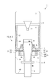
必要な量の合金Aを注湯したならば、図3に示すように、駆動ロッド8を降下させることで、遮熱体7の鋳型通路7Aを通じて鋳型Mを冷却室5の内部へ緩やかな速度で移動させる。このときの鋳型Mの移動速度は、例えば1時間に数十センチ程度とされる。
必要な量の合金Aを注湯したならば、図3に示すように、駆動ロッド8を降下させることで、遮熱体7の鋳型通路7Aを通じて鋳型Mを冷却室5の内部へ緩やかな速度で移動させる。このときの鋳型Mの移動速度は、例えば1時間に数十センチ程度とされる。
冷却室5の内部は、鋳型Mの内部の合金Aの融点よりも低い温度に保持されているので、鋳型Mが冷却室5に移動されるのに従って、凝固界面は徐々に上方へ移動していき、方向性凝固がなされる。
鋳型Mを降下させながら、ガス供給ノズル22から鋳型Mに向けて冷却ガスCGを吹き付けるとともに、水冷ジャケット26に冷却水CWを循環させることで、冷却機構20は遮熱体7の直下において鋳型Mを冷却する。駆動ロッド8の降下動作に連動してアクチュエータ23を動作させることで、それぞれのガス供給ノズル22を後退させる。これにより、それぞれのガス供給ノズル22から鋳型Mまでの距離を一定に保つ。
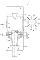
鋳型Mを降下させる過程で、図4に示すように、鋳型Mの最も太い部分が遮熱体7の鋳型通路7Aを通過するときに、ガス供給ノズル22が最も後退する後退位置に達する。この後退位置においても、それぞれのガス供給ノズル22から鋳型Mまでの距離が一定に保たれる。
鋳型Mを降下させながら、ガス供給ノズル22から鋳型Mに向けて冷却ガスCGを吹き付けるとともに、水冷ジャケット26に冷却水CWを循環させることで、冷却機構20は遮熱体7の直下において鋳型Mを冷却する。駆動ロッド8の降下動作に連動してアクチュエータ23を動作させることで、それぞれのガス供給ノズル22を後退させる。これにより、それぞれのガス供給ノズル22から鋳型Mまでの距離を一定に保つ。
鋳型Mを降下させる過程で、図4に示すように、鋳型Mの最も太い部分が遮熱体7の鋳型通路7Aを通過するときに、ガス供給ノズル22が最も後退する後退位置に達する。この後退位置においても、それぞれのガス供給ノズル22から鋳型Mまでの距離が一定に保たれる。
必要な位置まで緩やかな速度で鋳型Mが降下したならば、冷却ステップが終了する。その後は、冷却室5から鋳型Mを取り出してから型ばらしをして、方向性凝固された鋳造品を得る。
[効 果]
本実施形態の鋳造装置1によれば、以下の効果を奏する。
鋳造装置1は、冷却室5において鋳型Mが降下するのにともなって、ガス供給ノズル22から冷却ガスCGを吹き付けて冷却するとともに、放射冷却部25による放射冷却をすることによって、鋳型Mの下端から上端に向かって冷却が行なわれる。したがって、本実施形態によれば、鋳型Mを冷却する速度を速くすることで温度勾配と凝固速度を向上しながら、方向性凝固を行なうことができる。これにより、機械的強度を増大した鋳造品を、鋳造欠陥を抑制しながら製造できる。
本実施形態の鋳造装置1によれば、以下の効果を奏する。
鋳造装置1は、冷却室5において鋳型Mが降下するのにともなって、ガス供給ノズル22から冷却ガスCGを吹き付けて冷却するとともに、放射冷却部25による放射冷却をすることによって、鋳型Mの下端から上端に向かって冷却が行なわれる。したがって、本実施形態によれば、鋳型Mを冷却する速度を速くすることで温度勾配と凝固速度を向上しながら、方向性凝固を行なうことができる。これにより、機械的強度を増大した鋳造品を、鋳造欠陥を抑制しながら製造できる。
特に、本実施形態は、進退可能なガス供給ノズル22を用い、ガス供給ノズル22の吐出端221と鋳型Mとの距離を一定に保ちながら冷却できるので、太さが異なる鋳型Mにおいても、常に高い冷却性能を維持することができる。
ここで、ガス供給ノズル22の進退に変えて、冷却ガスCGの供給量を増減することもできるが、これだと多量の冷却ガスCGが必要になるのに比べて、本実施形態は、冷却ガスCGの供給量を一定の最小限に抑えることができるので、鋳造品の製造コストを低く抑えることができる。しかも、ガス供給ノズル22を進退させる機構は簡易である利点もある。ただし、本発明に加えて冷却ガスCGの供給量を増減することを排除するものではない。
ここで、ガス供給ノズル22の進退に変えて、冷却ガスCGの供給量を増減することもできるが、これだと多量の冷却ガスCGが必要になるのに比べて、本実施形態は、冷却ガスCGの供給量を一定の最小限に抑えることができるので、鋳造品の製造コストを低く抑えることができる。しかも、ガス供給ノズル22を進退させる機構は簡易である利点もある。ただし、本発明に加えて冷却ガスCGの供給量を増減することを排除するものではない。
鋳造装置1は、冷却機構20をなすガス冷却部21と放射冷却部25が鉛直方向に直列に配列されているので、互いの冷却機能を阻害することなく、それぞれの冷却性能を発揮することができる。しかも、放射冷却部25はガス供給ノズル22及び吐出される冷却ガスCGに対しても放射冷却するので、ガス冷却部21による鋳型Mの冷却が最大限に発揮される。
特に、冷却機構20は、上からガス冷却部21、放射冷却部25の順に配置しており、降下する鋳型Mはガス供給ノズル22から吹き付けられる冷却ガスCGで冷却され、その後に、放射冷却部25により放射冷却に給される。したがって、本実施形態によれば、ガス冷却部21と放射冷却部25の鉛直方向の配列が逆の場合に比べて、鋳型M自身の温度が高い加熱室4を出てすぐの領域に冷却ガスCGを供給できるために、ガス冷却部21による冷却性能を最大限に発揮させることができる。
特に、冷却機構20は、上からガス冷却部21、放射冷却部25の順に配置しており、降下する鋳型Mはガス供給ノズル22から吹き付けられる冷却ガスCGで冷却され、その後に、放射冷却部25により放射冷却に給される。したがって、本実施形態によれば、ガス冷却部21と放射冷却部25の鉛直方向の配列が逆の場合に比べて、鋳型M自身の温度が高い加熱室4を出てすぐの領域に冷却ガスCGを供給できるために、ガス冷却部21による冷却性能を最大限に発揮させることができる。
以上、本発明の好適な実施形態を説明したが、本発明の主旨を逸脱しない限り、上記実施形態で挙げた構成を取捨選択したり、他の構成に適宜変更したりすることができる。
例えば、図5に示すように、加熱室4から、所定の領域の周囲に配置された複数の鋳型M(M1,M2,M3,M4)を移動して、当該複数の鋳型Mに供給された溶融金属を方向性凝固させる鋳造装置1において、複数の鋳型M(M1,M2,M3,M4)を加熱室4より移動する駆動ロッド8と、所定の領域の内側から複数の鋳型M(M1,M2,M3,M4)を冷却ガスにより冷却する放射冷却部25と、所定の領域の外側から複数の鋳型M(M1,M2,M3,M4)を、ガス供給ノズル22から冷却ガスを吹き付けることにより冷却するガス冷却部21を備える鋳造装置1に対しても好適に適用することができる。
この鋳造装置1の場合は、図5(a)に示すようにガス供給ノズル22を進退させることもできるが、図5(b)に示すようにガス供給ノズル22を回転Rさせることにより、例えばその吐出端の位置を鋳型M(M1,M2,M3,M4)と干渉しない位置に移動させることもできる。
例えば、図5に示すように、加熱室4から、所定の領域の周囲に配置された複数の鋳型M(M1,M2,M3,M4)を移動して、当該複数の鋳型Mに供給された溶融金属を方向性凝固させる鋳造装置1において、複数の鋳型M(M1,M2,M3,M4)を加熱室4より移動する駆動ロッド8と、所定の領域の内側から複数の鋳型M(M1,M2,M3,M4)を冷却ガスにより冷却する放射冷却部25と、所定の領域の外側から複数の鋳型M(M1,M2,M3,M4)を、ガス供給ノズル22から冷却ガスを吹き付けることにより冷却するガス冷却部21を備える鋳造装置1に対しても好適に適用することができる。
この鋳造装置1の場合は、図5(a)に示すようにガス供給ノズル22を進退させることもできるが、図5(b)に示すようにガス供給ノズル22を回転Rさせることにより、例えばその吐出端の位置を鋳型M(M1,M2,M3,M4)と干渉しない位置に移動させることもできる。
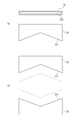
また、ガス冷却部21は、それぞれが独立する複数のガス供給ノズル22を備えているが、図6(a)に示すように、幅方向、つまり水平方向に延びるスリット状のノズル開口222を備えるガス供給ノズル22を用いることができる。このガス供給ノズル22は、吐出端221がV字状に形成されており、図6(b)に示すように、一対のガス供給ノズル22を、吐出端221同士が鋳型Mに対向させて用いる。図示を省略するが、このガス供給ノズル22もアクチュエータ23により進退される。
スリット状のノズル開口222を備えるガス供給ノズル22を用いると、冷却ガスCGの吐出流速が均一となることにより、鋳型Mの表面を均一に冷却できる。
スリット状のノズル開口222を備えるガス供給ノズル22を用いると、冷却ガスCGの吐出流速が均一となることにより、鋳型Mの表面を均一に冷却できる。
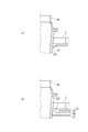
また、上述したガス供給ノズル22は、冷却ガスCGを水平方向に吐出する例を示すが、本発明はこれに限定されず、例えば、図7(a)に示すように、その先端を、加熱室4と反対側の下向きにするガス供給ノズル22を用いることが好ましい。そうすることで、加熱室4へ不必要に流入する冷却ガスCGの流量を減らすことが可能となるので、加熱ヒータ12の出力を低減できる。
また、上述したガス冷却部21は、ガス供給ノズル22が進退移動することで、鋳型Mとの距離を一定に維持するか、または、最適に調整できるが、本発明はこれに限るものでなく、図7(b)に示すように、定位置においてガス供給ノズル22が伸縮することで、冷却ガスCGを吐出する先端である吐出端221と鋳型Mとの距離を一定に維持、または、最適な距離に調整できる。ガス供給ノズル22のためのアクチュエータ23を設けるよりも、ガス供給ノズル22が占める領域を狭くできる可能性がある。なお、図7(b)は、ガス供給ノズル22が短いS、中間のM、長いLを個別に示しているが、実際には一本のガス供給ノズル22が定位置で伸縮する。また、ここではS、M及びLを示しているが、ガス供給ノズル22は無段階で伸縮されるものを使うことが好ましい。
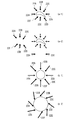
さらに、上述した実施形態は、ガス供給ノズル22のそれぞれを進退移動させているが、本発明におけるガス供給ノズル22の移動はこれに限るものでなく、例えば、複数のガス供給ノズル22のグループで水平方向へ平行移動させることができる。具体的には、図8(a-1)、(a-2)に示すように、ガス供給ノズル22A,22B,22C,22D,22E,22Fについては、これらをグループとして図中の左方向へ平行移動させ、また、ガス供給ノズル22G,22Hについては、これらをグループとして図中の下方向へ平行移動することができる。
また、複数のガス供給ノズル22のそれぞれを水平方向に回転させることもできる。具体的には、図8(b-1)、(b-2)に示すように、ガス供給ノズル22~22Hを回転することにより、ガス供給ノズル22~22Hで取り囲まれる領域を広狭させることができる。
ガス供給ノズル22の移動は、例示した図8に限るものでなく、例えば、図8(a-1)、(a-2)は複数のガス供給ノズル22~22Hをグループの単位で平行移動させるが、複数のガス供給ノズル22をグループの単位で回転移動させることもできる。
さらに、移動の形態としては、水平方向の移動だけでなく、鉛直方向に移動させてもよく、例えば、水平方向に回転軸を設定して、この回転軸を中心にしてガス供給ノズル22を揺動させることもできる。
また、複数のガス供給ノズル22のそれぞれを水平方向に回転させることもできる。具体的には、図8(b-1)、(b-2)に示すように、ガス供給ノズル22~22Hを回転することにより、ガス供給ノズル22~22Hで取り囲まれる領域を広狭させることができる。
ガス供給ノズル22の移動は、例示した図8に限るものでなく、例えば、図8(a-1)、(a-2)は複数のガス供給ノズル22~22Hをグループの単位で平行移動させるが、複数のガス供給ノズル22をグループの単位で回転移動させることもできる。
さらに、移動の形態としては、水平方向の移動だけでなく、鉛直方向に移動させてもよく、例えば、水平方向に回転軸を設定して、この回転軸を中心にしてガス供給ノズル22を揺動させることもできる。
また、本発明において、ガス供給ノズル22の移動を制御する手立ては任意であり、例えば、鋳造に供される鋳型Mの寸法、形状に関するデータを保持しておき、当該データに基づいてガス供給ノズル22の進退位置を調整できる。または、ガス供給ノズル22の吐出端221から鋳型Mの表面までの距離を計測する測距センサを備えておき、この測距センサで計測された鋳型Mの表面までの距離に基づいてガス供給ノズル22の進退位置を調整できる。
1 鋳造装置
2 真空室
3 注湯室
4 加熱室
4A 内壁面
5 冷却室
5A 内壁面
6 遮熱体
7 遮熱体
7A 鋳型通路
8 駆動ロッド
9 冷却テーブル
11 注湯ノズル
12 加熱ヒータ
20 冷却機構
21 ガス冷却部
22,22A,22B,22C,22D,22E,22F,22G ガス供給ノズル
221 吐出端
222 ノズル開口
23 アクチュエータ
25 放射冷却部
26 水冷ジャケット
CG 冷却ガス
CW 冷却水
M 鋳型
MA 上部開口
MB 下部開口
2 真空室
3 注湯室
4 加熱室
4A 内壁面
5 冷却室
5A 内壁面
6 遮熱体
7 遮熱体
7A 鋳型通路
8 駆動ロッド
9 冷却テーブル
11 注湯ノズル
12 加熱ヒータ
20 冷却機構
21 ガス冷却部
22,22A,22B,22C,22D,22E,22F,22G ガス供給ノズル
221 吐出端
222 ノズル開口
23 アクチュエータ
25 放射冷却部
26 水冷ジャケット
CG 冷却ガス
CW 冷却水
M 鋳型
MA 上部開口
MB 下部開口
Claims (11)
- 鋳型に溶融金属が注がれる加熱室と、
前記加熱室に隣接して設けられ、前記溶融金属が注がれた前記鋳型を移動させながら方向性凝固を行なう冷却室と、を備える鋳造装置であって、
前記冷却室は、
前記鋳型に向けて冷却ガスを吹き付ける、単数又は複数のガス供給ノズルを有するガス冷却部を備え、
それぞれの前記ガス供給ノズルは、前記鋳型の移動に対応して、前記冷却ガスの吐出端の位置が調整される、
ことを特徴とする鋳造装置。 - 前記ガス供給ノズルは、
移動することにより、前記吐出端の位置が調整される、
請求項1に記載の鋳造装置。 - 前記ガス供給ノズルは、
進退移動することにより、前記吐出端の位置が調整される、
請求項1に記載の鋳造装置。 - 前記ガス供給ノズルは、
定位置において伸縮することにより、前記吐出端の位置が調整される、
請求項1に記載の鋳造装置。 - 複数の前記ガス供給ノズルが、前記鋳型を取り囲むように、水平方向に放射状に設けられる、
請求項1に記載の鋳造装置。 - 前記ガス供給ノズルは、
水平方向に延びるスリット状のノズル開口を有する、
請求項1に記載の鋳造装置。 - 前記ガス供給ノズルは、
前記吐出端が、下向きとされている、
請求項1に記載の鋳造装置。 - 前記冷却室は、
放射により前記鋳型を冷却する放射冷却部を備え、
前記放射冷却部は、
前記加熱室と前記冷却室を区切る遮熱体の直下に設けられる前記ガス冷却部よりも下方において、前記ガス冷却部と鉛直方向に直列に配列される、
請求項1に記載の鋳造装置。 - 前記放射冷却部は、
前記ガス冷却部の下方において前記鋳型の周囲を取り囲み冷却水が循環する、円筒状の水冷ジャケットを備える、
請求項8に記載の鋳造装置。 - 複数の前記鋳型を備え、
それぞれの前記鋳型に対応する単数又は複数の前記ガス供給ノズルは、
前記鋳型の移動に対応して、前記吐出端の位置が調整される、
請求項1に記載の鋳造装置。 - 前記単数又は複数の前記ガス供給ノズルは、
水平方向に回転することで、前記吐出端の位置が調整される、
請求項10に記載の鋳造装置。
Priority Applications (1)
| Application Number | Priority Date | Filing Date | Title |
|---|---|---|---|
| US16/082,724 US10974319B2 (en) | 2016-03-11 | 2017-03-09 | Casting device |
Applications Claiming Priority (2)
| Application Number | Priority Date | Filing Date | Title |
|---|---|---|---|
| JP2016047733A JP6554052B2 (ja) | 2016-03-11 | 2016-03-11 | 鋳造装置 |
| JP2016-047733 | 2016-03-11 |
Publications (1)
| Publication Number | Publication Date |
|---|---|
| WO2017155037A1 true WO2017155037A1 (ja) | 2017-09-14 |
Family
ID=59789571
Family Applications (1)
| Application Number | Title | Priority Date | Filing Date |
|---|---|---|---|
| PCT/JP2017/009475 Ceased WO2017155037A1 (ja) | 2016-03-11 | 2017-03-09 | 鋳造装置 |
Country Status (3)
| Country | Link |
|---|---|
| US (1) | US10974319B2 (ja) |
| JP (1) | JP6554052B2 (ja) |
| WO (1) | WO2017155037A1 (ja) |
Families Citing this family (1)
| Publication number | Priority date | Publication date | Assignee | Title |
|---|---|---|---|---|
| US11998976B2 (en) | 2022-09-07 | 2024-06-04 | Ge Infrastructure Technology Llc | Systems and methods for enhanced cooling during directional solidification of a casting component |
Citations (3)
| Publication number | Priority date | Publication date | Assignee | Title |
|---|---|---|---|---|
| JP2002144019A (ja) * | 2000-11-02 | 2002-05-21 | Mitsubishi Heavy Ind Ltd | 一方向凝固鋳造方法及びその装置 |
| JP2003191067A (ja) * | 2001-12-21 | 2003-07-08 | Mitsubishi Heavy Ind Ltd | 方向性凝固鋳造装置、方向性凝固鋳造方法 |
| JP2014131816A (ja) * | 2012-11-06 | 2014-07-17 | Howmet Corp | 鋳造方法、装置及び製品 |
Family Cites Families (2)
| Publication number | Priority date | Publication date | Assignee | Title |
|---|---|---|---|---|
| DE19539770A1 (de) | 1995-06-20 | 1997-01-02 | Abb Research Ltd | Verfahren zur Herstellung eines gerichtet erstarrten Gießkörpers und Vorrichtung zur Durchführung dieses Verfahrens |
| EP1531020B1 (en) * | 2003-11-06 | 2007-02-07 | ALSTOM Technology Ltd | Method for casting a directionally solidified article |
-
2016
- 2016-03-11 JP JP2016047733A patent/JP6554052B2/ja active Active
-
2017
- 2017-03-09 US US16/082,724 patent/US10974319B2/en active Active
- 2017-03-09 WO PCT/JP2017/009475 patent/WO2017155037A1/ja not_active Ceased
Patent Citations (3)
| Publication number | Priority date | Publication date | Assignee | Title |
|---|---|---|---|---|
| JP2002144019A (ja) * | 2000-11-02 | 2002-05-21 | Mitsubishi Heavy Ind Ltd | 一方向凝固鋳造方法及びその装置 |
| JP2003191067A (ja) * | 2001-12-21 | 2003-07-08 | Mitsubishi Heavy Ind Ltd | 方向性凝固鋳造装置、方向性凝固鋳造方法 |
| JP2014131816A (ja) * | 2012-11-06 | 2014-07-17 | Howmet Corp | 鋳造方法、装置及び製品 |
Also Published As
| Publication number | Publication date |
|---|---|
| JP2017159338A (ja) | 2017-09-14 |
| JP6554052B2 (ja) | 2019-07-31 |
| US10974319B2 (en) | 2021-04-13 |
| US20190076919A1 (en) | 2019-03-14 |
Similar Documents
| Publication | Publication Date | Title |
|---|---|---|
| US10711617B2 (en) | Casting method, apparatus and product | |
| JP3919256B2 (ja) | 方向性凝固した鋳造物を製作する方法とこの方法を実施するための装置 | |
| RU2606817C2 (ru) | Способ направленной кристаллизации отливок при литье лопаток газовых турбин и устройство для получения отливок с направленной и монокристаллической структурой при литье лопаток газовых турбин | |
| US3620289A (en) | Method for casting directionally solified articles | |
| US6868893B2 (en) | Method and apparatus for directionally solidified casting | |
| JP5168591B2 (ja) | 連続鋳造用水冷鋳型及び鋳塊の製造方法 | |
| JP2004017158A (ja) | 方向性凝固方法および装置 | |
| EP3470150B1 (en) | Low-pressure casting mold | |
| US10675678B2 (en) | Apparatus for casting multiple components using a directional solidification process | |
| CN113118420A (zh) | 一种超细柱晶高温合金叶片及其激光定向凝固制备方法 | |
| JP6554052B2 (ja) | 鋳造装置 | |
| JP6017203B2 (ja) | 半凝固金属の製造装置、半凝固成形装置、半凝固金属の製造方法及び半凝固成形方法 | |
| CN109475931B (zh) | 定向凝固冷却熔炉及使用这种熔炉的冷却方法 | |
| JP4296566B2 (ja) | 鋳造用鋳込装置 | |
| JP6639963B2 (ja) | 鋳造装置 | |
| JP2009279628A (ja) | 一方向凝固鋳造装置 | |
| KR20150022000A (ko) | 인상식 연속 주조 장치 및 인상식 연속 주조 방법 | |
| JP2000343204A (ja) | 水平軸方向回転の方向性凝固装置とその方法 | |
| JP2015134377A (ja) | 高純度鋳塊の溶解連続鋳造装置及び高純度鋳塊の溶解連続鋳造方法 | |
| JP5579314B1 (ja) | 高純度鋳塊の溶解連続鋳造装置及び高純度鋳塊の溶解連続鋳造方法 | |
| JP2004105986A (ja) | 半凝固金属温度測定方法 | |
| KR20200055502A (ko) | 주조용 몰드, 주조 장치 및 주조방법 | |
| HK1195532A (en) | Casting method, apparatus and product | |
| JP2018075628A (ja) | 引上式連続鋳造装置 | |
| JP2009066621A (ja) | 鋳造装置 |
Legal Events
| Date | Code | Title | Description |
|---|---|---|---|
| NENP | Non-entry into the national phase |
Ref country code: DE |
|
| 121 | Ep: the epo has been informed by wipo that ep was designated in this application |
Ref document number: 17763377 Country of ref document: EP Kind code of ref document: A1 |
|
| 122 | Ep: pct application non-entry in european phase |
Ref document number: 17763377 Country of ref document: EP Kind code of ref document: A1 |