WO2017154577A1 - 輻射ヒータ装置 - Google Patents
輻射ヒータ装置 Download PDFInfo
- Publication number
- WO2017154577A1 WO2017154577A1 PCT/JP2017/006588 JP2017006588W WO2017154577A1 WO 2017154577 A1 WO2017154577 A1 WO 2017154577A1 JP 2017006588 W JP2017006588 W JP 2017006588W WO 2017154577 A1 WO2017154577 A1 WO 2017154577A1
- Authority
- WO
- WIPO (PCT)
- Prior art keywords
- occupant
- heater
- temperature
- target temperature
- radiation heater
- Prior art date
- Legal status (The legal status is an assumption and is not a legal conclusion. Google has not performed a legal analysis and makes no representation as to the accuracy of the status listed.)
- Ceased
Links
Images







Classifications
-
- B—PERFORMING OPERATIONS; TRANSPORTING
- B60—VEHICLES IN GENERAL
- B60H—ARRANGEMENTS OF HEATING, COOLING, VENTILATING OR OTHER AIR-TREATING DEVICES SPECIALLY ADAPTED FOR PASSENGER OR GOODS SPACES OF VEHICLES
- B60H1/00—Heating, cooling or ventilating devices
- B60H1/22—Heating, cooling or ventilating devices the heat source being other than the propulsion plant
- B60H1/2215—Heating, cooling or ventilating devices the heat source being other than the propulsion plant the heat being derived from electric heaters
- B60H1/2218—Heating, cooling or ventilating devices the heat source being other than the propulsion plant the heat being derived from electric heaters controlling the operation of electric heaters
-
- B—PERFORMING OPERATIONS; TRANSPORTING
- B60—VEHICLES IN GENERAL
- B60H—ARRANGEMENTS OF HEATING, COOLING, VENTILATING OR OTHER AIR-TREATING DEVICES SPECIALLY ADAPTED FOR PASSENGER OR GOODS SPACES OF VEHICLES
- B60H1/00—Heating, cooling or ventilating devices
- B60H1/00642—Control systems or circuits; Control members or indication devices for heating, cooling or ventilating devices
- B60H1/00814—Control systems or circuits characterised by their output, for controlling particular components of the heating, cooling or ventilating installation
- B60H1/00821—Control systems or circuits characterised by their output, for controlling particular components of the heating, cooling or ventilating installation the components being ventilating, air admitting or air distributing devices
- B60H1/00835—Damper doors, e.g. position control
- B60H1/00849—Damper doors, e.g. position control for selectively commanding the induction of outside or inside air
-
- B—PERFORMING OPERATIONS; TRANSPORTING
- B60—VEHICLES IN GENERAL
- B60H—ARRANGEMENTS OF HEATING, COOLING, VENTILATING OR OTHER AIR-TREATING DEVICES SPECIALLY ADAPTED FOR PASSENGER OR GOODS SPACES OF VEHICLES
- B60H1/00—Heating, cooling or ventilating devices
- B60H1/22—Heating, cooling or ventilating devices the heat source being other than the propulsion plant
-
- B—PERFORMING OPERATIONS; TRANSPORTING
- B60—VEHICLES IN GENERAL
- B60H—ARRANGEMENTS OF HEATING, COOLING, VENTILATING OR OTHER AIR-TREATING DEVICES SPECIALLY ADAPTED FOR PASSENGER OR GOODS SPACES OF VEHICLES
- B60H1/00—Heating, cooling or ventilating devices
- B60H1/22—Heating, cooling or ventilating devices the heat source being other than the propulsion plant
- B60H1/2215—Heating, cooling or ventilating devices the heat source being other than the propulsion plant the heat being derived from electric heaters
- B60H1/2226—Electric heaters using radiation
-
- B—PERFORMING OPERATIONS; TRANSPORTING
- B60—VEHICLES IN GENERAL
- B60H—ARRANGEMENTS OF HEATING, COOLING, VENTILATING OR OTHER AIR-TREATING DEVICES SPECIALLY ADAPTED FOR PASSENGER OR GOODS SPACES OF VEHICLES
- B60H1/00—Heating, cooling or ventilating devices
- B60H1/00007—Combined heating, ventilating, or cooling devices
- B60H1/00207—Combined heating, ventilating, or cooling devices characterised by the position of the HVAC devices with respect to the passenger compartment
- B60H2001/00228—Devices in the interior of the passenger compartment
Definitions
- the present disclosure relates to a radiation heater device.
- Patent Document 1 describes that the output of the radiant heater is controlled in accordance with a thermal load that varies depending on the heating capacity required in the passenger compartment.
- the passenger gets in the passenger compartment for a certain period of time or more, and is comfortable for a passenger whose body is sufficiently warm.
- a problem has been found that, for example, a cold occupant who has just entered from outside the vehicle is not necessarily in a comfortable state. For this reason, it is preferable to provide heating equal to or greater than the calculated heat load for a cold occupant who has just entered from outside the vehicle.
- the present disclosure has been made in view of such problems, and an object thereof is to provide a radiation heater device capable of improving the thermal sensation of a vehicle occupant.
- a radiation heater device includes a radiation heater that radiates radiant heat to a vehicle occupant, and a control unit that controls an output of the radiation heater.
- the information regarding the thermal sensation of the passenger is acquired, and the output of the radiant heater is controlled based on the information regarding the thermal sensation.
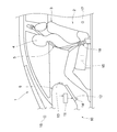
- FIG. 1 is a diagram illustrating a schematic configuration of a vehicle interior of a vehicle to which the radiation heater device according to the first embodiment of the present disclosure is applied.
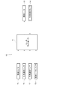
- FIG. 2 is a block diagram showing the configuration of the radiation heater device according to the first embodiment.
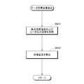
- FIG. 3 is a flowchart showing switching control of a target temperature calculation method for the radiant heater in the first embodiment.
- FIG. 4 is a flowchart showing a subroutine process performed in the heater target temperature calculation process in step S105 in FIG.
- FIG. 5 is a flowchart showing a subroutine process performed in the heater target temperature correction process of step S107 in FIG.
- FIG. 6 is a diagram illustrating an example of a heater target temperature characteristic used in the first embodiment.
- FIG. 1 is a diagram illustrating a schematic configuration of a vehicle interior of a vehicle to which the radiation heater device according to the first embodiment of the present disclosure is applied.
- FIG. 2 is a block diagram showing the configuration of the radiation heater device according to the first embodiment.
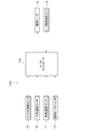
- FIG. 7 is a block diagram showing the configuration of the radiation heater device according to the second embodiment.
- FIG. 8 is a flowchart showing switching control of the target temperature calculation method of the radiant heater in the second embodiment.
- FIG. 9 is a diagram illustrating a schematic configuration of a vehicle interior of a vehicle to which the radiation heater device according to the third embodiment is applied.
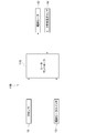
- FIG. 10 is a block diagram showing the configuration of the radiation heater device according to the third embodiment.
- FIG. 11 is a flowchart showing target temperature calculation control of the radiant heater in the third embodiment.
- FIG. 12 is a flowchart showing a subroutine process performed in the heater target temperature calculation process in step S503 in FIG.
- FIG. 13 is a diagram illustrating an example of a heater target temperature characteristic used in the third embodiment.
- FIG. 14 is a block diagram illustrating a configuration of a modified example of the embodiment.
- the first embodiment will be described with reference to FIGS. First, with reference to FIG.1 and FIG.2, the structure of the radiation heater apparatus 10 which concerns on 1st Embodiment is demonstrated.
- the radiant heater device 10 is a heating device that uses radiant heat, and constitutes a part of the heating device for the interior of the vehicle compartment 2 of the vehicle 1.
- the radiant heater device 10 is an electric heater that generates heat by being fed from a power source such as a battery or a generator mounted on the vehicle 1.
- the radiant heater device 10 is installed in the passenger compartment 2 so that radiant heat can be radiated to the feet of the passenger 4 seated on the seat 3 in the passenger compartment 2.
- a seating sensor 15 for detecting the seating state of the occupant 4 is installed in each seat 3 of the vehicle 1.
- the seating sensor 15 sends a seating signal indicating this state to the ECU in the vehicle 1, the heater controller 11 of the radiation heater device 10 described later, and the like. Output (it can also be expressed that the seating signal is turned on).
- the vehicle 1 is also provided with an outside air temperature sensor 16 that detects an outside air temperature that is a temperature outside the vehicle 1 and an inside air temperature sensor 17 that detects an inside air temperature that is the temperature inside the passenger compartment 2 of the vehicle 1. ing.
- the outside air temperature sensor 16 and the inside air temperature sensor 17 output information corresponding to the outside air temperature and the inside air temperature to the ECU in the vehicle 1, the heater controller 11 of the radiation heater device 10 to be described later, and the like.
- each seat 3 is provided with a buckle connection sensor 18 for detecting the connection state of the buckle of the seat belt 5.
- the buckle connection sensor 18 sends a buckle connection signal indicating this state to the ECU in the vehicle 1 or a radiant heater device 10 to be described later when the buckle of the seat belt 5 is connected to the seat 3 where the sensor is installed. To the heater controller 11 or the like (it can also be expressed that the buckle connection signal is turned on).
- the state in which the buckle connection sensor 18 outputs a buckle connection signal can be said to be a state in which the occupant 4 is seated on the seat 3 where the sensor is installed, and the occupant 4 is wearing the seat belt 5. Therefore, the buckle connection sensor 18 functions as a seat belt sensor for detecting the seat belt wearing state of the occupant 4.
- the radiant heater device 10 includes a heater controller 11 (control unit), a radiant heater 12, a radiant heater switch 13, and a heater surface temperature sensor 14.
- the heater controller 11 is a control device that controls the operation of the radiation heater 12.
- the heater controller 11 is electrically connected to the seating sensor 15, the outside air temperature sensor 16, the inside air temperature sensor 17, the radiation heater switch 13, the heater surface temperature sensor 14, and the radiation heater 12.
- the heater controller 11 controls the output of the radiant heater 12 based on various information input from the seating sensor 15, the outside air temperature sensor 16, the inside air temperature sensor 17, the radiant heater switch 13, and the heater surface temperature sensor 14.
- the radiant heater 12 is a heat generating device that can radiate radiant heat to the passenger 4 of the vehicle 1.
- the radiant heater 12 is installed in the passenger compartment 2 so as to radiate radiant heat to the feet of the passenger 4 seated in the seat 3.
- the radiant heater 12 can be installed on the wall surface in the passenger compartment 2.
- the radiant heater 12 is attached to the occupant 4 on the lower surface of the instrument panel 6 disposed in front of the seat 3. It can be installed to face each other.
- the radiant heater switch 13 is an input device that receives an operation input of the occupant 4 regarding the operation of the radiant heater 12.
- the radiation heater switch 13 receives an operation command for executing the operation of the radiation heater 12 when the radiation heater switch 13 is turned on by the operation of the passenger 4. Moreover, when it will be in an OFF state, the operation command which stops operation
- the radiant heater switch 13 can switch the output of the radiant heater 12 in multiple stages in the ON state.
- the radiant heater switch 13 can switch the output of the radiant heater 12 in three stages, for example, low output (Lo), medium output (Mi), and high output (Hi).
- the heater controller 11 can vary the heater target temperature under the same conditions according to the stage selected by the radiant heater switch 13 (hereinafter referred to as a heater output setting signal).
- the heater surface temperature sensor 14 detects the surface temperature of the radiant heater 12.
- the heater surface temperature sensor 14 outputs information corresponding to the surface temperature of the radiant heater 12 to the heater controller 11.
- the heater controller 11 is configured to acquire information related to the thermal sensation of the occupant 4 and to control the output of the radiant heater 12 based on the acquired information.
- the thermal sensation of the occupant 4 can also be expressed as an index that can express the feeling of heat and cold (thermal sensation) felt by the occupant 4 on a single scale.
- the “occupant 4 gets on the vehicle 1, which is calculated based on the information on the seating state of the passenger 4 detected by the seating sensor 15 as“ information related to the thermal sensation of the passenger ”acquired by the heater controller 11. Apply later elapsed time.
- the heater controller 11 switches the calculation method of the target temperature of the radiation heater 12 based on this elapsed time. Specifically, when the elapsed time after the occupant 4 gets into the vehicle 1 is less than a predetermined value, the occupant 4 has just entered the vehicle from outside the vehicle, and therefore, compared with the occupant who remains in the passenger compartment 2. Since the body is cold and the feeling of heat is thought to be cold, correction is performed to raise the target temperature in order to supply stronger radiant heat to the occupant.
- step S101 it is determined whether or not the radiation heater switch (SW) 13 is on.
- the process proceeds to step S102, and when it is in the off state (No in step S101), the process proceeds to step S109.
- step S102 it is determined whether or not the seating signal input from the seating sensor 15 is in an off state.
- the seating signal is on (No in step S102)
- the process proceeds to step S103.
- the seating signal is off (Yes in step S102)
- the process proceeds to step S109.
- step S103 as a result of the determinations in steps S101 and S102, the radiation heater switch 13 is in the on state and the seating signal is in the on state, that is, the radiation heater 12 is in operation and the seat 3 is turned on. Since the occupant 4 is in a seated state, it is determined whether or not a predetermined ⁇ or more has elapsed since the seating signal was turned on. If ⁇ minutes or more have elapsed since the seating signal was turned on (Yes in step S103), the process proceeds to step S104, and if the elapsed time since the seating signal was turned on is less than ⁇ minutes (No in step S103), the process proceeds to step S106.
- step S104 as a result of the determination in step S104, since a predetermined time after the occupant is seated on the seat has passed ⁇ minutes or more, the target temperature correction bit is set to 0 to use a normal target temperature calculation method. Is done.
- step S104 the process proceeds to step S105.
- step S105 a “heater target temperature calculation” process, which is a normal target temperature calculation method, is performed. Specific processing of “heater target temperature calculation” is steps S201 to S202 in the subroutine processing shown in FIG.
- step S201 the inside air temperature information is acquired from the inside air temperature sensor 17, and the heater output setting information (any of Hi, Mi, Lo) is acquired from the radiation heater switch 13.
- a target temperature is calculated from a predetermined heater target temperature characteristic based on the inside air temperature and the heater output setting acquired in step S201.
- the heater target temperature characteristic for example, the characteristic shown in FIG. 6 can be used.
- the horizontal axis in FIG. 6 represents the inside air temperature or the outside air temperature [° C.] (here, the inside air temperature), and the vertical axis in FIG. 6 represents the heater target temperature [° C.].
- three types of characteristics indicating the correspondence relationship between the inside air temperature and the target temperature are set according to the heater output setting in three stages.
- step S202 the process returns to the main flow and proceeds to step S108.
- step S106 as a result of the determination in step S104, since the predetermined time after the occupant is seated in the seat is less than ⁇ minutes, the target temperature correction bit is set to 1 in order to perform correction for temporarily raising the target temperature. Is set.
- step S107 the process proceeds to step S107.
- step S107 a “heater target temperature correction” process, which is a process for temporarily increasing the target temperature, is performed.
- Specific processing of “heater target temperature correction” is steps S301 to S304 in the subroutine processing shown in FIG.
- step S301 the inside air temperature information is obtained from the inside air temperature sensor 17, the outside air temperature information is obtained from the outside air temperature sensor 16, and the heater output setting information (any one of Hi, Mi, Lo) is obtained from the radiation heater switch 13. Obtained from.
- step S302 the target temperature A is calculated from predetermined heater target temperature characteristics based on the inside air temperature and the heater output setting acquired in step S301.
- the characteristic shown in FIG. 6 can be used for the heater target temperature characteristic as in step S202.
- step S303 the target temperature B is calculated from predetermined heater target temperature characteristics based on the outside air temperature and heater output setting acquired in step S301.
- the heater target temperature characteristics the characteristics shown in FIG. 6 can be used as in steps S202 and S302.
- the horizontal axis in FIG. 6 is the outside air temperature [° C.].
- step S304 the heater target temperature is calculated using the target temperature A based on the inside air temperature calculated in step S302 and the target temperature B based on the outside air temperature calculated in step S303.
- the heater target temperature can be calculated by, for example, the following equation (1).
- A is the target temperature [° C.] based on the inside air temperature calculated in step S302
- B is the target temperature [° C.] based on the outside air temperature calculated in step S303.
- T is an elapsed time [minute] after the seating signal is switched from the off state to the on state
- ⁇ is a predetermined time [minute], for example, 5 minutes.
- ⁇ also functions as a reference value for switching between the heater target temperature calculation process in step S105 and the heater target temperature correction process in step S107.
- k is a coefficient that varies according to the elapsed time T. The closer the elapsed time T is to 0, the closer the value is to 1. The closer the elapsed time is to ⁇ , the closer to 0.
- the first term (A) on the right side is a target temperature calculated from the heater target temperature characteristic shown in FIG. 6 based on the inside air temperature and the heater output setting. This is the same as the heater target temperature calculated in the normal target temperature calculation method.
- the second term on the right side (k * C) functions as a correction term for raising the target temperature A of the first term.
- k is a variable that varies according to the elapsed time T
- C is a variable determined by a deviation between the target temperature B and the target temperature A.
- the raised amount is larger, and as the elapsed time T approaches the predetermined time ⁇ , the raised amount tends to be smaller.
- the second term is that the larger the deviation between the target temperature B based on the outside air temperature and the target temperature A based on the inside air temperature, that is, the lower the outside air temperature is, the larger the amount of raising, and the outside air temperature There exists a tendency for the amount of raising to become small, so that it is close to inside air temperature.
- step S108 the radiant heater 12 is controlled to be in an on state, and the output of the radiant heater 12 is controlled based on the heater target temperature calculated in step S105 or step S107.
- the heater controller 11 feedback-controls the output of the radiant heater 12 based on the information on the actual surface temperature of the radiant heater 12 input from the heater surface temperature sensor 14, thereby setting the surface temperature of the radiant heater 12 to the heater target temperature. can do.
- this control flow ends.
- step S109 as a result of the determinations in steps S101 and S102, the radiation heater switch 13 is in the off state or the seating signal is in the off state, so the radiation heater 12 is controlled to the off state, and this control flow ends. To do.
- the radiant heater device 10 of the first embodiment includes a radiant heater 12 that radiates radiant heat to the passenger 4 of the vehicle 1, and a heater controller 11 that controls the output of the radiant heater 12.
- the controller 11 acquires “information relating to the thermal sensation of the passenger 4” and controls the output of the radiation heater 12 based on this information.
- the passenger 4 who has been in the passenger compartment 2 for a certain period of time and whose body is sufficiently warmed is compared with the passenger 4 who has just entered from the outside of the vehicle, the passenger compartment 2 having the same temperature is compared.
- the feeling of heat felt by the occupant 4 that is, an index that can express the sensation of heat and cold felt by the occupant 4 (heating sensation) on a single scale
- the radiation heater device 10 according to the first embodiment can control the output of the radiation heater 12 based on “information related to the thermal sensation of the occupant 4” by the above configuration. Appropriate heating can be provided according to the individual thermal sensation of the occupant 4 such as providing radiant heat with a relatively larger output than the occupant 4. As a result, it is possible to improve the feeling of heat and the feeling of heating for each occupant 4 of the vehicle 1.
- the above-described “output control of the radiant heater 12 based on information related to the thermal sensation of the passenger 4” specifically takes the following configuration in the radiant heater device 10 of the first embodiment. That is, the heater controller 11 calculates the elapsed time after the occupant 4 gets on the vehicle 1 as “information related to the thermal sensation of the occupant 4” based on the information on the sitting state of the occupant 4 detected by the seating sensor 15. The calculation method of the target temperature of the radiation heater 12 is switched based on the elapsed time.
- the elapsed time after the occupant 4 gets on is highly correlated with the thermal sensation of the occupant 4. For example, if the elapsed time is short, the occupant 4's body is cold and the thermal sensation is low, and if the elapsed time is long, the occupant 4's body is sufficiently warm and the thermal sensation is high. As described above, by switching the calculation method of the target temperature of the radiation heater 12 based on the elapsed time, it is possible to provide appropriate heating according to the thermal sensation of the occupant 4.
- the heater controller 11 is the temperature in the compartment 2 of the vehicle 1 when the elapsed time after the occupant 4 gets into the vehicle 1 is equal to or greater than the predetermined value ⁇ .
- a target temperature is set based on the inside air temperature, and when the elapsed time is less than the predetermined value ⁇ , correction for raising the target temperature is performed.
- the target temperature of the radiant heater 12 can be raised and the output can be increased from the normal time. Therefore, the thermal sensation of the occupant 4 can be improved appropriately.
- the above-described “correction for raising the target temperature” specifically takes the following configuration in the radiation heater device 10 of the first embodiment. That is, as described with reference to Equation (1), the heater controller 11 performs a correction to increase the target temperature raising amount as the elapsed time is shorter, and the outside temperature that is the temperature outside the vehicle 1 is further increased. The correction is performed to increase the amount of raising the target temperature as the temperature is lower than the inside air temperature. With this configuration, it is possible to appropriately correct the target temperature increase of the radiant heater 12 necessary for improving the thermal sensation of the occupant 4.
- the radiation heater device 10 ⁇ / b> A uses a buckle connection signal acquired from the buckle connection sensor 18 as input information instead of the seating information acquired from the seating sensor 15. This is different from the radiation heater device 10 of the first embodiment.
- the operation of the radiation heater device 10A according to the second embodiment will be described with reference to the flowchart of FIG. 8 are the same as steps S101 and S104 to S109 in the flowchart of FIG. 3, and thus description thereof is omitted.
- the heater target temperature calculation process in step S405 executes the subroutine process shown in FIG. 4 similarly to the first embodiment, and the heater target temperature correction process in step S407 performs the subroutine shown in FIG. 5 as in the first embodiment. Execute the process.
- step S402 it is determined whether or not the buckle connection signal input from the buckle connection sensor 18 is in an off state.
- the process proceeds to step S403.
- the buckle connection signal is in the off state (Yes in step S402), the process proceeds to step S409.
- step S403 as a result of the determinations in steps S401 and S402, the radiation heater switch 13 is on and the buckle connection signal is on, that is, the radiation heater 12 is operating and the seat 3 Since the passenger 4 is seated with the seat belt on, it is determined whether or not a predetermined ⁇ or more has elapsed since the buckle connection signal was turned on.
- ⁇ minutes or more have elapsed since the buckle connection signal is turned on Yes in step S403), the process proceeds to step S404, and when the elapsed time since the buckle connection signal is turned on is less than ⁇ minutes (No in step S403), the process proceeds to step S406.
- the above-described “output control of the radiation heater 12 based on information related to the thermal sensation of the passenger 4” has the following configuration. That is, the heater controller 11 ⁇ / b> A determines the elapsed time after the occupant 4 gets on the vehicle 1 as “information about the thermal sensation of the occupant 4” based on the information on the seat belt wearing state of the occupant 4 detected by the buckle connection sensor 18. The calculation method of the target temperature of the radiation heater 12 is switched based on the calculated elapsed time.
- the radiation heater device 10A of the second embodiment has a feature common to the first embodiment in which the calculation method of the target temperature of the radiation heater 12 is switched based on the elapsed time after the occupant 4 gets on.
- the radiation heater device 10B according to the third embodiment is different from the first and second embodiments in that an IR (infrared) sensor 19 is used as input information.
- the heater controller 11B is different from the first and second embodiments in that the information from the seating sensor 15, the outside air temperature sensor 16, the inside air temperature sensor 17, and the buckle connection sensor 18 is not used. .
- the vehicle 1 is provided with an IR sensor 19.
- the IR sensor 19 detects the surface temperature of the human body.
- the IR sensor 19 is installed, for example, in the vicinity of the radiant heater 12 so as to detect the surface temperature of the portion of the occupant 4 (for example, the foot part under the knee) irradiated with the radiant heat from the radiant heater 12.
- the IR sensor 19 outputs information corresponding to the temperature in the detection region to the ECU in the vehicle 1, the heater controller 11B of the radiation heater device 10B, and the like.
- crew 4 detected by the IR sensor 19 is applied as "information regarding a passenger
- the heater controller 11 sets the target temperature of the radiant heater 12 based on this surface temperature. Specifically, as the surface temperature is lower, the occupant 4 has just entered the vehicle from the outside of the vehicle, so the body is cold compared to the occupant staying in the passenger compartment 2, and the thermal feeling is also colder. Since it is possible, the heater target temperature is made relatively high. On the other hand, as the surface temperature is higher, it is considered that a sufficient time has passed since the occupant 4 got on and the thermal sensation was sufficiently recovered, so the heater target temperature is relatively lowered.
- step S501 it is determined whether or not the radiation heater switch (SW) 13 is turned on.
- the process proceeds to step S502.
- the process proceeds to step S505.
- step S502 it is determined whether or not the presence of the passenger 4 can be detected based on the IR sensor signal input from the IR sensor 19. For example, when the IR sensor signal detects a temperature distribution different from the surface temperature of the seat 3, the heater controller 11 ⁇ / b> B can determine that the passenger 4 is in the seat 3.
- the process proceeds to step S503.
- the process proceeds to step S505.
- step S503 as a result of the determination in steps S501 and S502, the radiant heater switch 13 is in the on state, and the occupant 4 can be detected by the IR sensor signal, so the “heater target temperature calculation” process is performed.
- Specific processing of “heater target temperature calculation” is steps S601 to S602 shown in FIG.
- step S601 the surface temperature information of the occupant 4 is acquired from the IR sensor 19, and the heater output setting information (any of Hi, Mi, Lo) is acquired from the radiation heater switch 13.
- a target temperature is calculated from predetermined heater target temperature characteristics based on the occupant surface temperature and heater output setting acquired in step S601.
- the heater target temperature characteristic for example, the characteristic shown in FIG. 13 can be used.
- the horizontal axis in FIG. 13 represents the passenger surface temperature [° C.]
- the vertical axis in FIG. 13 represents the heater target temperature [° C.].
- the characteristics shown in FIG. 13 are the same as the characteristics shown in FIG.
- step S504 the radiant heater 12 is controlled to be in an ON state, and the output of the radiant heater 12 is controlled based on the heater target temperature calculated in step S503.
- the heater controller 11B feedback-controls the output of the radiant heater 12 based on information on the actual surface temperature of the radiant heater 12 input from the heater surface temperature sensor 14, thereby setting the surface temperature of the radiant heater 12 to the heater target temperature. can do.
- this control flow ends.
- step S505 as a result of the determinations in steps S501 and S502, the radiant heater switch 13 is in the off state or the occupant 4 cannot be detected by the IR sensor signal. End the control flow.
- the method of detecting the presence or absence of the occupant 4 in step S502 includes a seating signal input from the seating sensor 15 and a buckle connection signal input from the buckle connection sensor 18 in addition to the method using the IR sensor 19 described above. You may use it in combination.
- the above-described “output control of the radiant heater 12 based on information related to the thermal sensation of the occupant 4” specifically has the following configuration. That is, the heater controller 11B uses the surface temperature of the occupant 4 detected by the IR sensor 19 as “information regarding the thermal sensation of the occupant 4”, and sets the target temperature of the radiant heater 12 based on the surface temperature.
- the surface temperature of the occupant 4 detected by the IR sensor 19 (for example, the lower part of the knee of the occupant 4 to which the radiant heat is supplied by the radiant heater 12) is highly correlated with the thermal sensation of the occupant 4. For example, if the surface temperature is low, the occupant 4's body is cold and the thermal sensation is low, and if the surface temperature is high, the occupant 4's body is sufficiently warm and the thermal sensation is high. Therefore, as described above, by setting the target temperature of the radiant heater 12 based on the surface temperature, it is possible to provide appropriate heating according to the thermal sensation of the occupant 4.
- the information on the surface temperature of the occupant 4 detected by the IR sensor 19 has a strong correlation with “information on the thermal sensation of the occupant 4”. Therefore, by applying the occupant surface temperature as input information, it is possible to accurately estimate the thermal sensation of the occupant 4 and to further control the output of the radiant heater 12 in accordance with the thermal sensation of the occupant 4. be able to.
- the IR sensor 19 can be replaced with other sensors that can measure the surface temperature of the occupant 4.
- FIG. 14 a configuration in which various sensors are electrically connected to the heater controllers 11, 11A, and 11B of the radiation heater devices 10, 10A, and 10B and signals are directly input from the various sensors is illustrated.
- the radiation heater devices 10, 10A, and 10B are not limited to these configurations.
- various sensors are electrically connected to the A / C ECU 100 at the upper level of the heater controllers 11, 11 ⁇ / b> A, 11 ⁇ / b> B, and the A / C ECU 100 receives signals input from the various sensors as heaters. It is good also as a structure which controls the radiation heater 12 based on the various sensor signals which transmitted to the controller 11,11A, 11B and the heater controller 11,11A, 11B received from A / C ECU100.
- the seating signal of the seating sensor 15, the buckle connection signal of the buckle connection sensor 18, and the IR of the IR sensor 19 are used. Although the configuration using the sensor signal is illustrated, these signals may be used in combination.
- the configuration for determining whether or not the occupant 4 is seated on the seat 3 is exemplified.
- the predetermined unit after it is determined that the occupant 4 is not seated.
- a configuration may be adopted in which it is determined again whether or not the user is seated within a time period (for example, several seconds to several tens of seconds). That is, in the first embodiment, the detection of the sitting state of the occupant 4 by the seating sensor 15 (that is, the processing of step S102) is performed for a predetermined unit time (for example, several seconds to several tens of seconds) after it is determined that the seating sensor 15 is not seated. It is good also as a structure performed again within seconds.
- the detection of the seating state of the occupant 4 by the buckle connection sensor 18 (that is, the process of step S402) is performed for a predetermined unit time (for example, several seconds to several seconds) after it is determined that the passenger is not seated.
- the configuration may be performed again within 10 seconds.
- step S102 even when it is determined that the occupant 4 is not seated in the process of step S102 even though the occupant 4 is actually seated, it is immediately after the determination (for example, it can be detected that the occupant 4 is seated several seconds to several tens of seconds later. Thereby, even when it is determined that the occupant 4 is not seated in this way, it can be detected that the occupant 4 is seated. Further, when it is detected that the occupant 4 is seated as described above, the subsequent processing (that is, the processing of steps S103 to S105, S106, etc.) may be performed.
- the posture is changed after the occupant 4 is seated. For example, a case where the user sits down for a while, or a case where the passenger leaves the vehicle momentarily due to a passenger's response at the time of stopping or the like is assumed.
- the third embodiment determines whether or not the occupant 4 exists within a predetermined unit time (for example, several seconds to several tens of seconds) after it is determined that the occupant 4 does not exist. Such a determination may be performed again.
- a predetermined unit time for example, several seconds to several tens of seconds
- the same effect as described above can be obtained. That is, in the case of this configuration, even when it is determined that the occupant 4 is not present even though the occupant 4 is actually present, the presence of the occupant 4 is detected. can do.
Landscapes
- Physics & Mathematics (AREA)
- Thermal Sciences (AREA)
- Engineering & Computer Science (AREA)
- Mechanical Engineering (AREA)
- Air-Conditioning For Vehicles (AREA)
Abstract
本開示に係る輻射ヒータ装置(10,10A,10B)は、車両(1)の乗員(4)に対して輻射熱を放射する輻射ヒータ(12)と、輻射ヒータの出力を制御する制御部(11,11A,11B)と、を備える。制御部は、乗員の温熱感に関する情報を取得し、温熱感に関する情報に基づき輻射ヒータの出力を制御する。
Description
本出願は、2016年3月11日に出願された日本国特許出願2016-048435号に基づくものであって、その優先権の利益を主張するものであり、その特許出願の全ての内容が、参照により本明細書に組み込まれる。
本開示は、輻射ヒータ装置に関する。
輻射熱を利用して対象を暖めることができる輻射ヒータ装置を車両の車室内に設置する構成が知られている。このような構成に関して、例えば特許文献1には、車室内に必要とされる暖房能力により変動する熱負荷に応じて、輻射ヒータの出力を制御することが記載されている。
特許文献1に記載の輻射ヒータの制御手法では、車室内に一定時間以上乗車しており、体が十分に暖まった乗員に対しては、快適な状態となる。しかしながら、発明者の詳細な検討の結果、例えば車外から入ってきたばかりの体の冷え切った乗員に対しては、必ずしも快適な状態とならない、という課題が見出された。このため、車外から入ってきたばかりの体の冷え切った乗員などに対しては、算出された熱負荷以上の暖房を提供することが好ましい。
本開示はこのような課題に鑑みてなされたものであり、その目的は、車両の乗員の温熱感の向上を図ることができる輻射ヒータ装置を提供することにある。
上記課題を解決するために、本開示に係る輻射ヒータ装置は、車両の乗員に対して輻射熱を放射する輻射ヒータと、前記輻射ヒータの出力を制御する制御部と、を備え、前記制御部は、前記乗員の温熱感に関する情報を取得し、前記温熱感に関する情報に基づき前記輻射ヒータの出力を制御する。
この構成により、例えば体の冷え切った乗員には、充分に暖まっている乗員よりも相対的に大きな出力で輻射熱を提供するなど、乗員の個々の温熱感に応じて適切な暖房を提供することができる。この結果、車両の乗員ごとに温熱感や暖房感を向上することが可能となる。
本開示によれば、車両の乗員の温熱感の向上を図ることができる輻射ヒータ装置を提供することができる。
以下、添付図面を参照しながら本開示の実施形態について説明する。説明の理解を容易にするため、各図面において同一の構成要素に対しては可能な限り同一の符号を付して、重複する説明は省略する。
[第1実施形態]
図1~図6を参照して第1実施形態について説明する。まず図1及び図2を参照して、第1実施形態に係る輻射ヒータ装置10の構成について説明する。
輻射ヒータ装置10は、輻射熱を利用する暖房装置であり、車両1の車室2内のための暖房装置の一部を構成している。輻射ヒータ装置10は、車両1に搭載された電池、発電機などの電源から給電されて発熱する電気的なヒータである。輻射ヒータ装置10は、車室2内の座席3に着座している乗員4に対して、この乗員4の足元に輻射熱を放射することができるように、車室2内に設置されている。
車両1の各座席3には、乗員4の着座状態を検出する着座センサ15が設置されている。着座センサ15は、このセンサが設置される座席3に乗員4が着座している状態のとき、この状態を示す着座信号を車両1内のECUや後述する輻射ヒータ装置10のヒータコントローラ11などに出力する(着座信号がオン状態となる、とも表現できる)。
また、車両1には、車両1の外部の温度である外気温度を検出する外気温度センサ16と、車両1の車室2内の温度である内気温度を検出する内気温度センサ17とが設置されている。外気温度センサ16及び内気温度センサ17は、外気温度及び内気温度に対応する情報を車両1内のECUや後述する輻射ヒータ装置10のヒータコントローラ11などに出力する。
また、各座席3には、シートベルト5のバックルの接続状態を検出するバックル接続センサ18が設置されている。バックル接続センサ18は、このセンサが設置される座席3において、シートベルト5のバックルが接続されている状態のとき、この状態を示すバックル接続信号を車両1内のECUや後述する輻射ヒータ装置10のヒータコントローラ11などに出力する(バックル接続信号がオン状態となる、とも表現できる)。バックル接続センサ18がバックル接続信号を出力する状態とは、このセンサが設置される座席3に乗員4が着座し、この乗員4がシートベルト5を装着している状態といえる。したがって、バックル接続センサ18は、乗員4のシートベルト装着状態を検出するシートベルトセンサとして機能するものである。
輻射ヒータ装置10は、ヒータコントローラ11(制御部)と、輻射ヒータ12と、輻射ヒータスイッチ13と、ヒータ表面温度センサ14とを備える。
ヒータコントローラ11は、輻射ヒータ12の動作を制御する制御装置である。ヒータコントローラ11は、着座センサ15、外気温度センサ16、内気温度センサ17、輻射ヒータスイッチ13、ヒータ表面温度センサ14、輻射ヒータ12と電気的に接続されている。ヒータコントローラ11は、着座センサ15、外気温度センサ16、内気温度センサ17、輻射ヒータスイッチ13、ヒータ表面温度センサ14から入力される各種情報に基づき、輻射ヒータ12の出力を制御する。
輻射ヒータ12は、車両1の乗員4に対して輻射熱を放射することができる発熱装置である。輻射ヒータ12は、座席3に着座している乗員4の足元に輻射熱を放射するように車室2内に設置されている。輻射ヒータ12は、車室2内の壁面に設置することができ、例えば車両1の前側の座席3の場合には、座席3の前方に配置されるインストルメントパネル6の下面に、乗員4に対向するように設置することができる。
輻射ヒータスイッチ13は、輻射ヒータ12の動作に関する乗員4の操作入力を受け付ける入力装置である。輻射ヒータスイッチ13は、乗員4の操作によってオン状態となるとき、輻射ヒータ12の動作を実行させる操作指令を受け付ける。また、オフ状態となるとき、輻射ヒータ12の動作を停止させる操作指令を受け付ける。さらに、輻射ヒータスイッチ13は、オン状態において輻射ヒータ12の出力を多段階に切り替えることができる。輻射ヒータスイッチ13は、例えば、輻射ヒータ12の出力を、低出力(Lo)、中出力(Mi)、高出力(Hi)の3段階に切り替えることができる。ヒータコントローラ11は、輻射ヒータスイッチ13により選択される段階(以降ではヒータ出力設定信号という)に応じて、同一条件におけるヒータ目標温度を異ならせることができる。
ヒータ表面温度センサ14は、輻射ヒータ12の表面温度を検出する。ヒータ表面温度センサ14は、輻射ヒータ12の表面温度に対応する情報をヒータコントローラ11に出力する。
次に、図3~図6を参照して、第1実施形態に係る輻射ヒータ装置10の動作について説明する。輻射ヒータ装置10において、ヒータコントローラ11は、乗員4の温熱感に関する情報を取得し、この取得した情報に基づき輻射ヒータ12の出力を制御するよう構成されている。ここで「乗員4の温熱感」とは、乗員4が感じる暑さや寒さの感覚(温冷感覚)を単一の尺度で表すことができる指標、とも表現することができる。
第1実施形態では、ヒータコントローラ11が取得する「乗員の温熱感に関する情報」として、着座センサ15により検出される乗員4の着座状態の情報に基づき算出される、乗員4が車両1に乗車した後の経過時間を適用する。ヒータコントローラ11は、この経過時間に基づき、輻射ヒータ12の目標温度の算出手法を切り替える。具体的には、乗員4が車両1に乗車した後の経過時間が所定値未満のときには、乗員4はまだ車外から車内に入ったばかりであるため、車室2内に居続けている乗員と比較して体が冷えており、温熱感も寒い状態と考えられるので、より強い輻射熱を乗員に供給すべく目標温度を嵩上げする補正を行う。一方、経過時間が所定値以上のときには、乗員4が乗車してから充分な時間が経過し、温熱感も充分に回復したと考えられるので、内気温度に基づき目標温度を設定するという通常のヒータ出力制御を行う。
以下、図3のフローチャートに沿って、輻射ヒータ装置10により実施される、輻射ヒータ12の目標温度算出手法の切り替え制御について説明する。図3に示す処理は、ヒータコントローラ11によって例えば所定周期ごとに実行される。
ステップS101では、輻射ヒータスイッチ(SW)13がオン状態か否かが判定される。輻射ヒータスイッチ13がオン状態のとき(ステップS101のYes)ステップS102に進み、オフ状態のとき(ステップS101のNo)ステップS109に進む。
ステップS102では、着座センサ15から入力される着座信号がオフ状態か否かが判定される。着座信号がオン状態のとき(ステップS102のNo)ステップS103に進み、オフ状態のとき(ステップS102のYes)ステップS109に進む。
ステップS103では、ステップS101,S102の判定の結果、輻射ヒータスイッチ13がオン状態であり、かつ、着座信号がオン状態であるので、すなわち、輻射ヒータ12が作動中であり、かつ、座席3に乗員4が着座している状態であるので、着座信号がオン状態となってから所定のα分以上経過しているか否かが判定される。着座信号オンからα分以上経過しているとき(ステップS103のYes)ステップS104に進み、着座信号オンからの経過時間がα分未満のとき(ステップS103のNo)ステップS106に進む。
ステップS104では、ステップS104の判定の結果、乗員が座席に着座してからの所定時間がα分以上経過しているので、通常の目標温度算出手法を用いるべく、目標温度補正ビットが0に設定される。ステップS104の処理が完了するとステップS105に進む。
ステップS105では、通常の目標温度算出手法である「ヒータ目標温度算出」処理が行われる。「ヒータ目標温度算出」の具体的な処理は、図4に示すサブルーチン処理におけるステップS201~S202である。
ステップS201では、内気温度の情報が内気温度センサ17から取得され、ヒータ出力設定の情報(Hi,Mi,Loのいずれか)が輻射ヒータスイッチ13から取得される。
ステップS202では、ステップS201にて取得した内気温度及びヒータ出力設定に基づいて、所定のヒータ目標温度特性から目標温度が算出される。ここで、ヒータ目標温度特性は、例えば図6に示す特性を用いることができる。図6の横軸は、内気温度又は外気温度[℃](ここでは内気温度)を表し、図6の縦軸はヒータ目標温度[℃]を表す。図6では、内気温度と目標温度との対応関係を示す特性が、3段階のヒータ出力設定に応じて3種類設定されている。これらの3種類の特性は、内気温度が所定の低温側温度T1以下のときに目標温度が最大値となり、低温側温度T1から高温側温度T2までの区間で温度上昇に伴って単調減少し、内気温度が高温側温度T2のときに目標温度が最小値となる点で共通する。また、これらの3種類の特性は、目標温度の最大値及び最小値が、ヒータ出力設定のHi、Mi、Loの順番で段階的に小さくなるように設定されている。ステップS202の処理が完了するとメインフローに戻り、ステップS108に進む。
ステップS106では、ステップS104の判定の結果、乗員が座席に着座してからの所定時間がα分未満であるので、一時的に目標温度を嵩上げする補正を行うべく、目標温度補正ビットが1に設定される。ステップS106の処理が完了するとステップS107に進む。
ステップS107では、一時的に目標温度を嵩上げする補正を行う処理である「ヒータ目標温度補正」処理が行われる。「ヒータ目標温度補正」の具体的な処理は、図5に示すサブルーチン処理におけるステップS301~S304である。
ステップS301では、内気温度の情報が内気温度センサ17から取得され、外気温度の情報が外気温度センサ16から取得され、ヒータ出力設定の情報(Hi,Mi,Loのいずれか)が輻射ヒータスイッチ13から取得される。
ステップS302では、ステップS301にて取得した内気温度及びヒータ出力設定に基づいて、所定のヒータ目標温度特性から目標温度Aが算出される。ここで、ヒータ目標温度特性は、ステップS202と同様に図6に示す特性を用いることができる。
ステップS303では、ステップS301にて取得した外気温度及びヒータ出力設定に基づいて、所定のヒータ目標温度特性から目標温度Bが算出される。ここで、ヒータ目標温度特性は、ステップS202、S302と同様に図6に示す特性を用いることができる。本ステップでは、図6の横軸は外気温度[℃]となる。
ステップS304では、ステップS302にて算出された内気温度に基づく目標温度Aと、ステップS303にて算出された外気温度に基づく目標温度Bとを用いて、ヒータ目標温度が算出される。ヒータ目標温度は、例えば下記の(1)式により算出することができる。

ここで、AはステップS302にて算出された内気温度に基づく目標温度[℃]であり、BはステップS303にて算出された外気温度に基づく目標温度[℃]である。Cは、目標温度Bと目標温度Aとの偏差(B-A)[℃]であり、C≦0の場合はC=0とする。Tは、着座信号がオフ状態からオン状態に切り替わった後の経過時間[分]であり、αは、所定時間[分]であり、例えば5分である。αは、ステップS105のヒータ目標温度算出処理と、ステップS107のヒータ目標温度補正処理とを切り替えるための基準値としても機能する。kは、経過時間Tに応じて変動する係数であり、経過時間Tが0に近いほど1に近い値となり、経過時間がαに近いほど0に近い値となる。
ここで(1)式についてさらに述べると、右辺第一項(A)は、内気温度及びヒータ出力設定に基づいて、図6に示すヒータ目標温度特性から算出される目標温度であり、ステップS105の通常の目標温度算出手法において算出されるヒータ目標温度と同一である。右辺第二項(k*C)は、第一項の目標温度Aを嵩上げするための補正項として機能する。第二項において、kが経過時間Tに応じて変動する変数であり、Cが目標温度Bと目標温度Aとの偏差によって決まる変数である。第二項は、経過時間Tが短いほど嵩上げ量が大きく、経過時間Tが所定時間αに近づくほど嵩上げ量が小さくなる傾向がある。また、第二項は、外気温度に基づく目標温度Bと、内気温度に基づく目標温度Aとの偏差が大きいほど、つまり、外気温度が内気温度より低温であるほど嵩上げ量が大きく、外気温度が内気温度に近づくほど嵩上げ量が小さくなる傾向がある。ステップS304の処理が完了するとメインフローに戻り、ステップS108に進む。
ステップS108では、輻射ヒータ12がオン状態に制御され、ステップS105またはステップS107にて算出されたヒータ目標温度に基づいて輻射ヒータ12の出力が制御される。ヒータコントローラ11は、ヒータ表面温度センサ14から入力される輻射ヒータ12の実際の表面温度の情報に基づき、輻射ヒータ12の出力をフィードバック制御することによって、輻射ヒータ12の表面温度をヒータ目標温度にすることができる。ステップS108の処理が完了すると本制御フローを終了する。
ステップS109では、ステップS101,S102の判定の結果、輻射ヒータスイッチ13がオフ状態であるか、または、着座信号がオフ状態であるので、輻射ヒータ12がオフ状態に制御され、本制御フローを終了する。
次に、第1実施形態に係る輻射ヒータ装置10の効果について説明する。
車両1の車室2内に着座している乗員4を輻射ヒータの暖房提供の対象とする構成を考える。従来の輻射ヒータの制御手法では、例えば特許文献1のように、車室2内に必要とされる暖房能力により変動する熱負荷に応じて、輻射ヒータの出力を変動させる制御手法が提案されている。しかし、これらの制御手法では、車室2内に一定時間以上乗車しており、体が十分に暖まった乗員4に対しては、快適な状態となるが、例えば車外から入ってきたばかりの体の冷え切った乗員4に対しては、算出された熱負荷以上の暖房感が求められるケースが想定され、乗員4にとって充分な暖房提供を行えない虞がある。
これに対して、第1実施形態の輻射ヒータ装置10は、車両1の乗員4に対して輻射熱を放射する輻射ヒータ12と、輻射ヒータ12の出力を制御するヒータコントローラ11と、を備え、ヒータコントローラ11は、「乗員4の温熱感に関する情報」を取得し、この情報に基づき輻射ヒータ12の出力を制御する。
例えば、車室2内に一定時間以上乗車しており、体が十分に暖まっている乗員4と、車外から入ってきたばかりの体の冷え切った乗員4とを比較すると、同じ温度の車室2にいても乗員4が感じる温熱感(すなわち、乗員4が感じる暑さや寒さの感覚(温冷感覚)を単一の尺度で表すことができる指標)は異なるものとなる。第1実施形態の輻射ヒータ装置10は、上記構成によって、「乗員4の温熱感に関する情報」に基づき輻射ヒータ12の出力を制御できるので、例えば体の冷え切った乗員4には、充分に暖まっている乗員4よりも相対的に大きな出力で輻射熱を提供するなど、乗員4の個々の温熱感に応じて適切な暖房を提供することができる。この結果、車両1の乗員4ごとに温熱感や暖房感を向上することが可能となる。
また、上述した「乗員4の温熱感に関する情報に基づく輻射ヒータ12の出力制御」とは、第1実施形態の輻射ヒータ装置10では具体的には以下の構成をとる。すなわち、ヒータコントローラ11は、着座センサ15により検出される乗員4の着座状態の情報に基づき、乗員4が車両1に乗車した後の経過時間を「乗員4の温熱感に関する情報」として算出し、経過時間に基づき輻射ヒータ12の目標温度の算出手法を切り替える。
乗員4が乗車した後の経過時間は、乗員4の温熱感と高い相関があると考えられる。例えば、この経過時間が短ければ乗員4の体は冷えており温熱感が低い状態であり、経過時間が長ければ乗員4の体は充分に暖まっており温熱感は高い状態といえる。上記構成のとおり、経過時間に基づき輻射ヒータ12の目標温度の算出手法を切り替えることにより、乗員4の温熱感に応じた適切な暖房の提供が可能となる。
また、第1実施形態の輻射ヒータ装置10において、ヒータコントローラ11は、乗員4が車両1に乗車した後の経過時間が所定値α分以上のとき、車両1の車室2内の温度である内気温度に基づき目標温度を設定し、経過時間が所定値α未満のとき、目標温度を嵩上げする補正を行う。
この構成により、乗員4が車両1に乗車した後の経過時間が短く、乗員4の温熱感が比較的低いときには、輻射ヒータ12の目標温度を嵩上げして通常時より出力を増大させることができるので、乗員4の温熱感を適切に向上させることができる。
また、上述した「目標温度を嵩上げする補正」とは、第1実施形態の輻射ヒータ装置10では具体的には以下の構成をとる。すなわち、ヒータコントローラ11は、数式(1)を参照して説明したように、経過時間が短いほど目標温度の嵩上げ量を大きくする補正を行い、さらに、車両1の外部の温度である外気温度が内気温度に対して低くなるほど、目標温度の嵩上げ量を大きくする補正を行う。この構成により、乗員4の温熱感を向上させるために必要な輻射ヒータ12の目標温度の嵩上げ補正を適切に行うことができる。
[第2実施形態]
図7及び図8を参照して第2実施形態について説明する。図7に示すように、第2実施形態に係る輻射ヒータ装置10Aは、着座センサ15から取得される着座情報の代わりに、バックル接続センサ18から取得されるバックル接続信号を入力情報として用いる点で、第1実施形態の輻射ヒータ装置10と異なる。
第2実施形態に係る輻射ヒータ装置10Aの動作について、図8のフローチャートを参照して説明する。図8のフローチャートのステップS401,S404~S409の各処理は、図3のフローチャートのステップS101,S104~S109と同一の処理であるので説明を省略する。なお、ステップS405のヒータ目標温度算出処理は、第1実施形態と同様に図4に示すサブルーチン処理を実行し、ステップS407のヒータ目標温度補正処理は、第1実施形態と同様に図5のサブルーチン処理を実行する。
ステップS402では、バックル接続センサ18から入力されるバックル接続信号がオフ状態か否かが判定される。バックル接続信号がオン状態のとき(ステップS402のNo)ステップS403に進み、オフ状態のとき(ステップS402のYes)ステップS409に進む。
ステップS403では、ステップS401,S402の判定の結果、輻射ヒータスイッチ13がオン状態であり、かつ、バックル接続信号がオン状態であるので、すなわち、輻射ヒータ12が作動中であり、かつ、座席3に乗員4がシートベルトを装着して着座している状態であるので、バックル接続信号がオン状態となってから所定のα分以上経過しているか否かが判定される。バックル接続信号オンからα分以上経過しているとき(ステップS403のYes)ステップS404に進み、バックル接続信号オンからの経過時間がα分未満のとき(ステップS403のNo)ステップS406に進む。
第2実施形態の輻射ヒータ装置10Aにおいて、上述した「乗員4の温熱感に関する情報に基づく輻射ヒータ12の出力制御」とは具体的には以下の構成をとる。すなわち、ヒータコントローラ11Aは、バックル接続センサ18により検出される乗員4のシートベルト装着状態の情報に基づき、乗員4が車両1に乗車した後の経過時間を「乗員4の温熱感に関する情報」として算出し、経過時間に基づき輻射ヒータ12の目標温度の算出手法を切り替える。
このように、第2実施形態の輻射ヒータ装置10Aは、乗員4が乗車した後の経過時間に基づき輻射ヒータ12の目標温度の算出手法を切り替える、という第1実施形態と共通の特徴を有するので、第1実施形態と同様の効果を奏することができる。
[第3実施形態]
図9~図13を参照して第3実施形態について説明する。図10に示すように、第3実施形態に係る輻射ヒータ装置10Bは、IR(赤外線)センサ19を入力情報として用いる点で、第1、第2実施形態と異なる。また、図10に示すように、ヒータコントローラ11Bは、着座センサ15、外気温度センサ16、内気温度センサ17、バックル接続センサ18からの情報を利用しない点で、第1、第2実施形態と異なる。
図9及び図10に示すように、車両1にはIRセンサ19が設けられる。IRセンサ19は、人体の表面温度を検知する。IRセンサ19は、輻射ヒータ12からの輻射熱が照射される乗員4の部分(例えば膝下の足部)の表面温度を検知できるよう、例えば輻射ヒータ12の近傍に設置される。IRセンサ19は、検知領域の温度に対応する情報を車両1内のECUや輻射ヒータ装置10Bのヒータコントローラ11Bなどに出力する。
次に、図11~図13を参照して、第3実施形態に係る輻射ヒータ装置10Bの動作について説明する。第3実施形態では、ヒータコントローラ11Bが取得する「乗員の温熱感に関する情報」として、IRセンサ19により検出される乗員4の足部の表面温度の情報を適用する。ヒータコントローラ11は、この表面温度に基づき、輻射ヒータ12の目標温度を設定する。具体的には、表面温度が低いほど、乗員4はまだ車外から車内に入ったばかりであるため、車室2内に居続けている乗員と比較して体が冷えており、温熱感も寒い状態と考えられるので、ヒータ目標温度を相対的に高くする。一方、表面温度が高いほど、乗員4が乗車してから充分な時間が経過し、温熱感も充分に回復したと考えられるので、ヒータ目標温度を相対的に低くする。
以下、図11のフローチャートに沿って、輻射ヒータ装置10Bにより実施される、輻射ヒータ12の目標温度の算出制御について説明する。図11に示す処理は、ヒータコントローラ11Bによって例えば所定周期ごとに実行される。
ステップS501では、輻射ヒータスイッチ(SW)13がオン状態か否かが判定される。輻射ヒータスイッチ13がオン状態のとき(ステップS501のYes)ステップS502に進み、オフ状態のとき(ステップS501のNo)ステップS505に進む。
ステップS502では、IRセンサ19から入力されるIRセンサ信号により乗員4の存在を検知できるか否かが判定される。ヒータコントローラ11Bは、例えばIRセンサ信号が、座席3の表面温度とは異なる温度分布を検知したときに、乗員4が座席3にいると判定することができる。乗員4を検知したとき(ステップS502のYes)ステップS503に進み、乗員4を検知できないとき(ステップS502のNo)ステップS505に進む。
ステップS503では、ステップS501,S502の判定の結果、輻射ヒータスイッチ13がオン状態であり、かつ、IRセンサ信号により乗員4を検知できたので、「ヒータ目標温度算出」処理が行われる。「ヒータ目標温度算出」の具体的な処理は、図12に示すステップS601~S602である。
ステップS601では、乗員4の表面温度の情報がIRセンサ19から取得され、ヒータ出力設定の情報(Hi,Mi,Loのいずれか)が輻射ヒータスイッチ13から取得される。
ステップS602では、ステップS601にて取得した乗員表面温度及びヒータ出力設定に基づいて、所定のヒータ目標温度特性から目標温度が算出される。ここで、ヒータ目標温度特性は、例えば図13に示す特性を用いることができる。図13の横軸は、乗員表面温度[℃]を表し、図13の縦軸はヒータ目標温度[℃]を表す。図13に示す特性は、その他の点については図6に示した特性と同様である。ステップS602の処理が完了するとメインフローに戻り、ステップS504に進む。
ステップS504では、輻射ヒータ12がオン状態に制御され、ステップS503にて算出されたヒータ目標温度に基づいて輻射ヒータ12の出力が制御される。ヒータコントローラ11Bは、ヒータ表面温度センサ14から入力される輻射ヒータ12の実際の表面温度の情報に基づき、輻射ヒータ12の出力をフィードバック制御することによって、輻射ヒータ12の表面温度をヒータ目標温度にすることができる。ステップS504の処理が完了すると本制御フローを終了する。
ステップS505では、ステップS501,S502の判定の結果、輻射ヒータスイッチ13がオフ状態であるか、または、IRセンサ信号により乗員4を検知できなかったので、輻射ヒータ12がオフ状態に制御され、本制御フローを終了する。
なお、ステップS502における乗員4の有無を検出する手法は、上記のIRセンサ19を用いる手法の他に、着座センサ15から入力される着座信号や、バックル接続センサ18から入力されるバックル接続信号を組み合わせて用いても良い。
第3実施形態の輻射ヒータ装置10Bにおいて、上述した「乗員4の温熱感に関する情報に基づく輻射ヒータ12の出力制御」とは具体的には以下の構成をとる。すなわち、ヒータコントローラ11Bは、IRセンサ19により検出される乗員4の表面温度を「乗員4の温熱感に関する情報」として用い、表面温度に基づき輻射ヒータ12の目標温度を設定する。
IRセンサ19により検知される乗員4(例えば輻射ヒータ12により輻射熱が供給される乗員4の膝下部)の表面温度は、乗員4の温熱感と高い相関があると考えられる。例えば、この表面温度が低ければ乗員4の体は冷えており温熱感が低い状態であり、表面温度が高ければ乗員4の体は充分に暖まっており温熱感は高い状態といえる。したがって、上記構成のとおり、表面温度に基づき輻射ヒータ12の目標温度を設定することにより、乗員4の温熱感に応じた適切な暖房の提供が可能となる。
また、IRセンサ19により検知される乗員4の表面温度の情報は、「乗員4の温熱感に関する情報」との相関が強いと考えられる。このため、乗員表面温度を入力情報として適用することにより、乗員4の温熱感を精度良く推定することが可能となり、輻射ヒータ12の出力制御をより一層乗員4の温熱感に則したものとすることができる。なお、第3実施形態の輻射ヒータ装置10Bでは、IRセンサ19を、乗員4の表面温度を計測することができる他のセンサ類に置き換えることも可能である。
[変形例]
図14を参照して上記実施形態の変形例について説明する。第1~第3実施形態では、輻射ヒータ装置10,10A,10Bのヒータコントローラ11,11A,11Bに各種センサが電気的に接続され、各種センサから直接信号が入力される構成を例示したが、輻射ヒータ装置10,10A,10Bはこれらの構成に限られない。例えば図14に示すように、各種センサ類が、ヒータコントローラ11,11A,11Bの上位のA/C ECU100に電気的に接続され、A/C ECU100が、各種センサ類から入力される信号をヒータコントローラ11,11A,11Bに送信し、ヒータコントローラ11,11A,11BがA/C ECU100から受信した各種センサ信号に基づき輻射ヒータ12を制御する構成としてもよい。
以上、具体例を参照しつつ本開示の実施の形態について説明した。しかし、本開示はこれらの具体例に限定されるものではない。すなわち、これら具体例に、当業者が適宜設計変更を加えたものも、本開示の特徴を備えている限り、本開示の範囲に包含される。例えば、前述した各具体例が備える各要素及びその配置、材料、条件、形状、サイズなどは、例示したものに限定されるわけではなく適宜変更することができる。また、前述した各実施の形態が備える各要素は、技術的に可能な限りにおいて組み合わせることができ、これらを組み合わせたものも本開示の特徴を含む限り本開示の範囲に包含される。
第1、第2実施形態に示した、乗員4の乗車後の経過時間に基づく輻射ヒータ12の目標温度の嵩上げ補正手法と、第3実施形態に示した、乗員4の表面温度に基づく輻射ヒータ12の目標温度の設定手法とを組み合わせる構成としてもよい。
また、第1~第3実施形態では、乗員4が座席3に着座しているか否かの判定手法として、それぞれ着座センサ15の着座信号、バックル接続センサ18のバックル接続信号、IRセンサ19のIRセンサ信号を利用する構成を例示したが、これらの信号を組み合わせて使用してもよい。
また、第1、第2実施形態では、座席3に乗員4が着座している状態であるか否かの判定を行う構成を例示したが、着座していないと判定された後の所定の単位時間(例えば、数秒~数十秒)内に、着座している状態であるか否かの判定を再度行う構成としても良い。すなわち、第1実施形態において、着座センサ15による乗員4の着座状態の検出(すなわち、ステップS102の処理)を、着座していないと判定された後の所定の単位時間(例えば、数秒~数十秒)内に再び行う構成としても良い。また、第2実施形態において、バックル接続センサ18による乗員4の着座状態の検出(すなわち、ステップS402の処理)を、着座していないと判定された後の所定の単位時間(例えば、数秒~数十秒)内に再び行う構成としても良い。
この構成によれば、実際は乗員4が着座しているも同然の状態であるにも関わらずステップS102の処理にて乗員4が着座していないと判定された場合においても、該判定の直後(例えば、数秒~数十秒後)に乗員4が着座していることを検出することができる。これにより、このように乗員4が着座していないと判定された場合でも、乗員4が着座している状態であることを検出することができる。また、このように乗員4が着座している状態であることを検出したときにその後の処理(すなわち、ステップS103~S105、S106の処理など)を行う構成としても良い。尚、「実際は乗員4が着座しているも同然の状態であるにも関わらず乗員4が着座していないと判定とされる場合」としては、例えば、乗員4が着座した後に、姿勢を変えるために座りなおした場合或いは停車時の乗降者の対応等で瞬間的に離席した場合などが想定される。
また、これと同様に、第3実施形態において、乗員4が存在していないと判定された後の所定の単位時間(例えば、数秒~数十秒)内に、乗員4が存在しているか否かの判定を再度行う構成としても良い。この構成の場合も、上記と同様の効果が得られる。すなわち、この構成の場合、実際は乗員4が存在しているも同然の状態であるにも関わらず乗員4が存在していないと判定された場合においても、乗員4が存在していることを検出することができる。また、このように乗員4が存在していることを検出したときにその後の処理(すなわち、ステップS503、S504の処理)を行う構成としても良い。
Claims (7)
- 車両(1)の乗員(4)に対して輻射熱を放射する輻射ヒータ(12)と、
前記輻射ヒータの出力を制御する制御部(11,11A,11B)と、
を備え、
前記制御部は、前記乗員の温熱感に関する情報を取得し、前記温熱感に関する情報に基づき前記輻射ヒータの出力を制御する、
輻射ヒータ装置(10,10A,10B)。 - 前記乗員の着座状態を検出する着座センサ(15)を備え、
前記制御部(11)は、前記着座センサにより検出される前記着座状態の情報に基づき、前記乗員が前記車両に乗車した後の経過時間を前記温熱感に関する情報として算出し、前記経過時間に基づき前記輻射ヒータの目標温度の算出手法を切り替える、
請求項1に記載の輻射ヒータ装置(10)。 - 前記乗員のシートベルト装着状態を検出するシートベルトセンサ(18)を備え、
前記制御部(11A)は、前記シートベルトセンサにより検出される前記シートベルト装着状態の情報に基づき、前記乗員が前記車両に乗車した後の経過時間を前記温熱感に関する情報として算出し、前記経過時間に基づき前記輻射ヒータの目標温度の算出手法を切り替える、
請求項1または2に記載の輻射ヒータ装置(10A)。 - 前記制御部(11,11A)は、
前記経過時間が所定値以上のとき、前記車両の車室内の温度である内気温度に基づき前記目標温度を設定し、
前記経過時間が所定値未満のとき、前記目標温度を嵩上げする補正を行う、
請求項2または3に記載の輻射ヒータ装置(10,10A)。 - 前記制御部は、前記経過時間が短いほど前記目標温度の嵩上げ量(k・C)を大きくする補正を行う、
請求項4に記載の輻射ヒータ装置。 - 前記制御部は、前記車両の外部の温度である外気温度が、前記内気温度に対して低くなるほど、前記目標温度の嵩上げ量を大きくする補正を行う、
請求項5に記載の輻射ヒータ装置。 - 前記乗員の表面温度を検出する温度センサ(19)を備え、
前記制御部(11B)は、前記温度センサにより検出される前記表面温度を前記温熱感に関する情報として用い、前記表面温度に基づき前記輻射ヒータの目標温度を設定する、請求項1~6のいずれか1項に記載の輻射ヒータ装置(10B)。
Priority Applications (2)
| Application Number | Priority Date | Filing Date | Title |
|---|---|---|---|
| US16/083,253 US10906378B2 (en) | 2016-03-11 | 2017-02-22 | Radiant heater device |
| DE112017001261.9T DE112017001261T5 (de) | 2016-03-11 | 2017-02-22 | Heizstrahlereinrichtung |
Applications Claiming Priority (2)
| Application Number | Priority Date | Filing Date | Title |
|---|---|---|---|
| JP2016-048435 | 2016-03-11 | ||
| JP2016048435A JP6528705B2 (ja) | 2016-03-11 | 2016-03-11 | 輻射ヒータ装置 |
Publications (1)
| Publication Number | Publication Date |
|---|---|
| WO2017154577A1 true WO2017154577A1 (ja) | 2017-09-14 |
Family
ID=59789341
Family Applications (1)
| Application Number | Title | Priority Date | Filing Date |
|---|---|---|---|
| PCT/JP2017/006588 Ceased WO2017154577A1 (ja) | 2016-03-11 | 2017-02-22 | 輻射ヒータ装置 |
Country Status (4)
| Country | Link |
|---|---|
| US (1) | US10906378B2 (ja) |
| JP (1) | JP6528705B2 (ja) |
| DE (1) | DE112017001261T5 (ja) |
| WO (1) | WO2017154577A1 (ja) |
Cited By (1)
| Publication number | Priority date | Publication date | Assignee | Title |
|---|---|---|---|---|
| JP2023149873A (ja) * | 2022-03-31 | 2023-10-16 | 株式会社デンソー | 車両用暖房装置 |
Families Citing this family (10)
| Publication number | Priority date | Publication date | Assignee | Title |
|---|---|---|---|---|
| US11077734B2 (en) * | 2016-04-25 | 2021-08-03 | Denso Corporation | Vehicle control system with idling stop control |
| US10814697B2 (en) * | 2017-08-17 | 2020-10-27 | Ford Global Technologies, Llc | Radiant heating system with infrared sensors for temperature feedback control |
| JP2019085095A (ja) * | 2017-11-01 | 2019-06-06 | 株式会社デンソー | 流体加熱装置 |
| WO2019087643A1 (ja) * | 2017-11-01 | 2019-05-09 | 株式会社デンソー | 流体加熱装置 |
| JP7246000B2 (ja) * | 2018-03-30 | 2023-03-27 | パナソニックIpマネジメント株式会社 | 車両用暖房装置及び車両用暖房装置を備えた車両 |
| EP3738802B1 (en) * | 2019-05-13 | 2024-09-11 | Volvo Car Corporation | Automatic temperature adjustment of vehicle compartment components |
| DE102019124054B4 (de) * | 2019-09-09 | 2025-08-28 | Hanon Systems | Verfahren zur Steuerung und Regelung einer Fahrzeugklimatisierungsanordnung |
| US11407278B2 (en) | 2019-09-26 | 2022-08-09 | GM Global Technology Operations LLC | Vehicle cabin thermal management system |
| KR102572539B1 (ko) * | 2020-12-14 | 2023-08-31 | 서울대학교산학협력단 | 복사열을 이용한 온열 역치 측정 시스템 및 그 시스템을 이용한 사용자 맞춤형 복사열 히터 제어 장치 |
| DE102021004188B4 (de) | 2021-08-17 | 2023-08-17 | Mercedes-Benz Group AG | Kraftfahrzeug mit einer Bodenheizvorrichtung |
Citations (7)
| Publication number | Priority date | Publication date | Assignee | Title |
|---|---|---|---|---|
| JPH04103427A (ja) * | 1990-08-21 | 1992-04-06 | Zexel Corp | 車両用空気調和装置 |
| JPH08183320A (ja) * | 1995-01-05 | 1996-07-16 | Mitsubishi Heavy Ind Ltd | 車両用空気調和装置 |
| JP2005059821A (ja) * | 2003-07-29 | 2005-03-10 | Nissan Motor Co Ltd | 車両用空調装置 |
| JP2005306095A (ja) * | 2004-04-19 | 2005-11-04 | Denso Corp | 車両用空調制御装置 |
| JP2012192829A (ja) * | 2011-03-16 | 2012-10-11 | Denso Corp | 車両用暖房装置 |
| JP2015223917A (ja) * | 2014-05-27 | 2015-12-14 | 株式会社デンソー | 車両用暖房装置 |
| JP2016022894A (ja) * | 2014-07-23 | 2016-02-08 | 株式会社オートネットワーク技術研究所 | 温度制御装置及び温度制御システム |
Family Cites Families (24)
| Publication number | Priority date | Publication date | Assignee | Title |
|---|---|---|---|---|
| JP2898364B2 (ja) * | 1990-07-06 | 1999-05-31 | 日本碍子株式会社 | 電極一体型ハニカムヒーター及びその製造方法 |
| DE10111223A1 (de) * | 2000-03-09 | 2001-09-13 | Denso Corp | Fahrzeugklimaanlage mit einem die manuelle Steuerungsbetätigung der Gebläsespannung lernenden Regelungssystem |
| JP3714261B2 (ja) * | 2002-02-12 | 2005-11-09 | 株式会社デンソー | 車両用シート空調装置 |
| US10227063B2 (en) * | 2004-02-26 | 2019-03-12 | Geelux Holdings, Ltd. | Method and apparatus for biological evaluation |
| JP2009046115A (ja) * | 2007-07-20 | 2009-03-05 | Denso It Laboratory Inc | 車両用空調装置及び車両用空調装置の制御方法 |
| CA2735664A1 (en) * | 2008-09-16 | 2010-03-25 | United States Gypsum Company | Heating system |
| JP2012056531A (ja) * | 2010-09-13 | 2012-03-22 | Denso Corp | 車両用輻射熱暖房装置 |
| US20120234932A1 (en) * | 2011-03-16 | 2012-09-20 | Denso Corporation | Vehicular heating system |
| JP2012228896A (ja) * | 2011-04-25 | 2012-11-22 | Denso Corp | 車両用輻射熱暖房装置 |
| US9371024B2 (en) * | 2012-02-13 | 2016-06-21 | Denso Corporation | Air-conditioner for vehicle |
| JP5988195B2 (ja) * | 2012-03-29 | 2016-09-07 | パナソニックIpマネジメント株式会社 | 機器制御装置、機器制御システムおよびプログラム |
| JP5988196B2 (ja) * | 2012-03-29 | 2016-09-07 | パナソニックIpマネジメント株式会社 | 機器制御装置、機器制御システムおよびプログラム |
| JP5954235B2 (ja) | 2013-03-28 | 2016-07-20 | 株式会社デンソー | ヒータ装置 |
| JP6127913B2 (ja) | 2013-03-29 | 2017-05-17 | 株式会社デンソー | 輻射ヒータ装置 |
| MY182329A (en) * | 2013-05-17 | 2021-01-19 | Panasonic Ip Corp America | Thermal image sensor and user interface |
| JP2016048435A (ja) | 2014-08-27 | 2016-04-07 | 京セラドキュメントソリューションズ株式会社 | 広告配信システム、広告配信装置、広告配信システムプログラム、広告配信プログラム、及び広告配信方法 |
| US20160207375A1 (en) * | 2015-01-20 | 2016-07-21 | Atieva, Inc. | Method of Operating a Preemptive Vehicle Temperature Control System |
| US10351029B2 (en) * | 2015-05-04 | 2019-07-16 | Hyundai America Technical Center, Inc. | Thermal wave-based seat heating |
| JP5866585B1 (ja) * | 2015-05-20 | 2016-02-17 | パナソニックIpマネジメント株式会社 | 受光センサ、それを用いた空気調和機および電子調理器 |
| CA2987273A1 (en) * | 2015-06-12 | 2016-12-15 | University Of Maryland, College Park | Comfort units and systems, methods, and devices for use thereof |
| JP6535613B2 (ja) * | 2016-01-29 | 2019-06-26 | 株式会社デンソー | 車両用空調装置 |
| JP6558490B2 (ja) * | 2016-02-23 | 2019-08-14 | 株式会社デンソー | 車両用空調装置 |
| US10647230B2 (en) * | 2016-02-23 | 2020-05-12 | Denso Corporation | Seat air conditioner |
| US20190063776A1 (en) * | 2017-08-22 | 2019-02-28 | Panasonic Intellectual Property Management Co., Ltd. | Air conditioning control system, air conditioning control apparatus, and air conditioning control method |
-
2016
- 2016-03-11 JP JP2016048435A patent/JP6528705B2/ja not_active Expired - Fee Related
-
2017
- 2017-02-22 US US16/083,253 patent/US10906378B2/en active Active
- 2017-02-22 DE DE112017001261.9T patent/DE112017001261T5/de active Pending
- 2017-02-22 WO PCT/JP2017/006588 patent/WO2017154577A1/ja not_active Ceased
Patent Citations (7)
| Publication number | Priority date | Publication date | Assignee | Title |
|---|---|---|---|---|
| JPH04103427A (ja) * | 1990-08-21 | 1992-04-06 | Zexel Corp | 車両用空気調和装置 |
| JPH08183320A (ja) * | 1995-01-05 | 1996-07-16 | Mitsubishi Heavy Ind Ltd | 車両用空気調和装置 |
| JP2005059821A (ja) * | 2003-07-29 | 2005-03-10 | Nissan Motor Co Ltd | 車両用空調装置 |
| JP2005306095A (ja) * | 2004-04-19 | 2005-11-04 | Denso Corp | 車両用空調制御装置 |
| JP2012192829A (ja) * | 2011-03-16 | 2012-10-11 | Denso Corp | 車両用暖房装置 |
| JP2015223917A (ja) * | 2014-05-27 | 2015-12-14 | 株式会社デンソー | 車両用暖房装置 |
| JP2016022894A (ja) * | 2014-07-23 | 2016-02-08 | 株式会社オートネットワーク技術研究所 | 温度制御装置及び温度制御システム |
Cited By (2)
| Publication number | Priority date | Publication date | Assignee | Title |
|---|---|---|---|---|
| JP2023149873A (ja) * | 2022-03-31 | 2023-10-16 | 株式会社デンソー | 車両用暖房装置 |
| JP7746902B2 (ja) | 2022-03-31 | 2025-10-01 | 株式会社デンソー | 車両用暖房装置 |
Also Published As
| Publication number | Publication date |
|---|---|
| US10906378B2 (en) | 2021-02-02 |
| JP2017159858A (ja) | 2017-09-14 |
| DE112017001261T5 (de) | 2018-11-29 |
| US20190070930A1 (en) | 2019-03-07 |
| JP6528705B2 (ja) | 2019-06-12 |
Similar Documents
| Publication | Publication Date | Title |
|---|---|---|
| JP6528705B2 (ja) | 輻射ヒータ装置 | |
| US11383624B2 (en) | Seat | |
| CN104340016B (zh) | 用于对车辆内室进行供暖的方法 | |
| US9045066B2 (en) | Heater control unit and vehicle seat heater | |
| EP3017998B1 (en) | Vehicle heating system | |
| US8926010B2 (en) | Vehicle seat | |
| US20200391634A1 (en) | Vehicle seat heater and vehicle seat | |
| JP5708292B2 (ja) | シートヒータ及びそれを備える車両用シート | |
| JP7035947B2 (ja) | シートヒータ装置 | |
| JP2018062297A (ja) | 温感付与システム | |
| JP2010064681A (ja) | 車両用暖房装置 | |
| JP6431800B2 (ja) | 乗物用シート | |
| US20200323301A1 (en) | Heating device | |
| JP6221985B2 (ja) | 輻射ヒータ装置 | |
| JP2016120777A5 (ja) | ||
| KR101664696B1 (ko) | 승객감지장치를 이용한 시트 히터 온도제어방법 | |
| JP2012239797A (ja) | 乗物用シート | |
| JP2017178130A (ja) | シートヒータおよび乗物用シート | |
| JP7168889B2 (ja) | シート | |
| JP7328559B2 (ja) | シートヒータおよび乗物用シート | |
| JP2022094185A (ja) | シートヒータ制御装置 | |
| JP7176502B2 (ja) | 温冷刺激システム | |
| JP2021075143A (ja) | 空調制御装置、空調装置の制御方法、およびプログラム | |
| JP6697153B2 (ja) | シート | |
| JP2020185822A (ja) | 空調システムおよびシート |
Legal Events
| Date | Code | Title | Description |
|---|---|---|---|
| 121 | Ep: the epo has been informed by wipo that ep was designated in this application |
Ref document number: 17762919 Country of ref document: EP Kind code of ref document: A1 |
|
| 122 | Ep: pct application non-entry in european phase |
Ref document number: 17762919 Country of ref document: EP Kind code of ref document: A1 |