WO2017154513A1 - 熱式質量流量センサ、当該熱式質量流量センサの製造方法、及び当該熱式質量流量センサを用いる熱式質量流量計 - Google Patents
熱式質量流量センサ、当該熱式質量流量センサの製造方法、及び当該熱式質量流量センサを用いる熱式質量流量計 Download PDFInfo
- Publication number
- WO2017154513A1 WO2017154513A1 PCT/JP2017/005816 JP2017005816W WO2017154513A1 WO 2017154513 A1 WO2017154513 A1 WO 2017154513A1 JP 2017005816 W JP2017005816 W JP 2017005816W WO 2017154513 A1 WO2017154513 A1 WO 2017154513A1
- Authority
- WO
- WIPO (PCT)
- Prior art keywords
- sensor
- thermal mass
- mass flow
- exhaust pipe
- internal space
- Prior art date
- Legal status (The legal status is an assumption and is not a legal conclusion. Google has not performed a legal analysis and makes no representation as to the accuracy of the status listed.)
- Ceased
Links
Images








Classifications
-
- G—PHYSICS
- G01—MEASURING; TESTING
- G01F—MEASURING VOLUME, VOLUME FLOW, MASS FLOW OR LIQUID LEVEL; METERING BY VOLUME
- G01F1/00—Measuring the volume flow or mass flow of fluid or fluent solid material wherein the fluid passes through a meter in a continuous flow
- G01F1/68—Measuring the volume flow or mass flow of fluid or fluent solid material wherein the fluid passes through a meter in a continuous flow by using thermal effects
- G01F1/684—Structural arrangements; Mounting of elements, e.g. in relation to fluid flow
- G01F1/6847—Structural arrangements; Mounting of elements, e.g. in relation to fluid flow where sensing or heating elements are not disturbing the fluid flow, e.g. elements mounted outside the flow duct
-
- G—PHYSICS
- G01—MEASURING; TESTING
- G01F—MEASURING VOLUME, VOLUME FLOW, MASS FLOW OR LIQUID LEVEL; METERING BY VOLUME
- G01F1/00—Measuring the volume flow or mass flow of fluid or fluent solid material wherein the fluid passes through a meter in a continuous flow
- G01F1/68—Measuring the volume flow or mass flow of fluid or fluent solid material wherein the fluid passes through a meter in a continuous flow by using thermal effects
- G01F1/684—Structural arrangements; Mounting of elements, e.g. in relation to fluid flow
-
- G—PHYSICS
- G01—MEASURING; TESTING
- G01F—MEASURING VOLUME, VOLUME FLOW, MASS FLOW OR LIQUID LEVEL; METERING BY VOLUME
- G01F1/00—Measuring the volume flow or mass flow of fluid or fluent solid material wherein the fluid passes through a meter in a continuous flow
- G01F1/68—Measuring the volume flow or mass flow of fluid or fluent solid material wherein the fluid passes through a meter in a continuous flow by using thermal effects
- G01F1/684—Structural arrangements; Mounting of elements, e.g. in relation to fluid flow
- G01F1/688—Structural arrangements; Mounting of elements, e.g. in relation to fluid flow using a particular type of heating, cooling or sensing element
-
- G—PHYSICS
- G01—MEASURING; TESTING
- G01F—MEASURING VOLUME, VOLUME FLOW, MASS FLOW OR LIQUID LEVEL; METERING BY VOLUME
- G01F1/00—Measuring the volume flow or mass flow of fluid or fluent solid material wherein the fluid passes through a meter in a continuous flow
- G01F1/68—Measuring the volume flow or mass flow of fluid or fluent solid material wherein the fluid passes through a meter in a continuous flow by using thermal effects
- G01F1/684—Structural arrangements; Mounting of elements, e.g. in relation to fluid flow
- G01F1/688—Structural arrangements; Mounting of elements, e.g. in relation to fluid flow using a particular type of heating, cooling or sensing element
- G01F1/69—Structural arrangements; Mounting of elements, e.g. in relation to fluid flow using a particular type of heating, cooling or sensing element of resistive type
-
- G—PHYSICS
- G01—MEASURING; TESTING
- G01F—MEASURING VOLUME, VOLUME FLOW, MASS FLOW OR LIQUID LEVEL; METERING BY VOLUME
- G01F15/00—Details of, or accessories for, apparatus of groups G01F1/00 - G01F13/00 insofar as such details or appliances are not adapted to particular types of such apparatus
- G01F15/18—Supports or connecting means for meters
-
- G—PHYSICS
- G01—MEASURING; TESTING
- G01F—MEASURING VOLUME, VOLUME FLOW, MASS FLOW OR LIQUID LEVEL; METERING BY VOLUME
- G01F5/00—Measuring a proportion of the volume flow
Definitions
- the present invention relates to a thermal mass flow sensor, a method of manufacturing the thermal mass flow sensor, and a thermal mass flow meter using the thermal mass flow sensor. More specifically, the present invention relates to a thermal mass flow sensor in which the high temperature durability of the coating layer of the sensor wire is improved, a method of manufacturing the thermal mass flow sensor, and a thermal mass flow using the thermal mass flow sensor About the total.
- Mass flow rate sensors are widely used, for example, for the purpose of detecting the mass flow rate of a process gas supplied into a chamber in a semiconductor manufacturing process.
- Various types of mass flow sensors are known in the art, among which thermal mass flow sensors are widely used because they can accurately measure the mass flow of process gases with a relatively simple structure. It is popular.
- the thermal mass flow rate sensor is a flow path through which a process gas flows, a bypass provided in the middle of the flow path, and a sensor tube which branches from the flow path upstream of the bypass and joins the flow path downstream of the bypass , A pair of sensor wires wound around the sensor tube, and a sensor circuit including a bridge circuit constituted by the sensor wire and the other resistive element.
- the bypass has a fluid resistance to the process gas and is configured to branch a portion of the process gas flowing in the flow path to the sensor tube at a constant rate. Therefore, by measuring the mass flow rate of the process gas flowing to the sensor tube, the mass flow rate of the process gas flowing to the flow path can be determined.
- the sensor wire When a predetermined current is applied to the sensor wire, the sensor wire generates heat and heat is given to the process gas flowing through the sensor tube. The heat moves from the upstream side to the downstream side as the process gas flows. This heat transfer causes a temperature difference between the upstream sensor wire and the downstream sensor wire, resulting in a difference in electrical resistance. As a result, a potential difference occurs between the ends of the bridge circuit. By detecting this potential difference by the sensor circuit, it is possible to measure the mass flow rate of the process gas flowing through the sensor tube.
- the surface of the sensor wire is insulated so that a short circuit (electrical contact) does not occur between the sensor wires and between the sensor wire and the sensor tube. It is common to be covered by a sexual covering layer.
- the material constituting the covering layer is required to have a function as an electrical insulator, a function as an adhesive, and a function as a conductor of heat.
- the sensor wire in order to heat the process gas flowing through the sensor tube, the sensor wire is heated by supplying a predetermined current to the sensor wire.
- flow sensors may be used at high temperatures.
- the material constituting the coating layer may chemically react with oxygen in the atmosphere to gradually disappear as a gas.
- the covering layer disappears, for example, electrical contact may occur between adjacent sensor wires, or electrical contact may occur between the sensor wire and the sensor tube.
- electrical contact occurs, the electrical resistance value of the sensor wire is lowered, which makes it difficult to heat the process gas by energization of the sensor wire, and the sensitivity as a flow rate sensor is lowered.
- a gap is generated between the sensor tube and the sensor wire, which impedes the movement of heat, making it difficult to heat the process gas by energizing the sensor wire, or reducing the sensitivity as a flow sensor.
- the inside of the package is made a vacuum or an inert gas atmosphere, and then made of a solder based material provided in the sealing hole. It has also been proposed to hermetically seal the package by heating and melting the sealing material (for example, by irradiating an electron beam, a laser beam or the like) (see, for example, Patent Document 3).
- the coating layer of the sensor wire for use at high temperature Loss can be suppressed.
- the thermal mass flow sensor sealed in a closed container in an inert atmosphere for the purpose of suppressing the disappearance of the coating layer of the sensor wire accompanying use at high temperature;
- airtightness refers to, for example, “a state in which a plurality of members are joined without a gap and fluid does not leak from between these members”.
- the bonding method capable of airtightly bonding a plurality of members in this manner for example, welding, brazing, diffusion bonding and the like can be mentioned.
- the thermal mass flow sensor according to the present invention (hereinafter sometimes referred to as “the sensor of the present invention") is inactive for the purpose of suppressing the disappearance of the covering layer of the sensor wire accompanying use at high temperatures. It is a thermal mass flow sensor enclosed in a closed container in the atmosphere.
- the sensor of the present invention comprises a sealed container, and a sensor tube in airtight communication with an inlet and an outlet formed on an outer wall defining the inner space of the sealed container and housed in the inner space of the sealed container.
- a pair of sensor wires wound around the sensor tube a covering layer covering at least a portion of the sensor wire wound around the sensor tube, and an outer wall provided with both ends of the pair of sensor wires outside the sealed container And a hermetic connector electrically connected to the external electrode.
- the internal space of the sealed container is sealed in an inert atmosphere.
- the senor according to the present invention further includes an exhaust pipe, which is a pipe that airtightly communicates the internal space of the sealed container with the outside through an exhaust hole, which is a through hole formed in the outer wall.
- an exhaust pipe which is a pipe that airtightly communicates the internal space of the sealed container with the outside through an exhaust hole, which is a through hole formed in the outer wall.
- the end of the exhaust pipe opposite to the exhaust hole is sealed by plastic deformation to form a sealed portion.
- the sealing portion may be further sealed by welding.
- the sensor of the present invention according to another preferred embodiment further comprises a cap having an inner space capable of receiving the seal and an opening, wherein the seal is inserted into the inner space of the cap through the opening.
- the cap and the exhaust pipe may be further sealed by welding.
- a pair of the first member which is a member in which the inlet and the outlet are formed, has a pair of the inlet and the outlet and the both ends of the sensor tube in airtight communication. Weld the sensor tube wound with the sensor wire.
- An exhaust pipe is welded to a third member, which is a member having an exhaust hole, of the plurality of members constituting the hermetic container, in such a manner as to be in airtight communication with the internal space of the hermetic container via the exhaust hole.
- Step 4 A plurality of members constituting the closed container are welded together to form the closed container.
- Step 5 After air is exhausted from the internal space through the exhaust pipe (for example, by a pressure reducing pump or the like), the end of the exhaust pipe opposite to the exhaust hole is sealed by plastic deformation to form a sealed portion.
- the inert gas is enclosed in the internal space through the exhaust pipe.
- the end of the exhaust pipe opposite to the exhaust hole may be sealed by plastic deformation to form a sealed portion.
- the inert gas may be enclosed in the internal space through the exhaust pipe.
- the sealing portion may be further sealed by welding.
- sealing is performed through the opening to the internal space capable of receiving the sealing portion and the internal space of the cap in which the opening is formed.
- the cap and the exhaust pipe may be further sealed by welding in a state in which the stopper is inserted.
- the specific detection gas is locally supplied to the outer surface of the closed container, and the inside of the inside via the exhaust pipe (for example, by a pressure reduction pump)
- the method may further include an air tightness test step of specifying a place where the gas for detection is supplied when the gas for detection is detected in the gas discharged from the space as a defective place having insufficient air tightness.
- the present invention also relates to a thermal mass flow meter (hereinafter sometimes referred to as "the present flow meter") using the sensor of the present invention having the configuration as described above.
- the flow meter of the present invention may further include a heat transfer block in surface contact with each of the installation surface of the base and the side surface of the closed container of the sensor of the present invention.
- the flow meter of the present invention may further include a temperature control block provided in contact with at least one side of the base and the heat transfer block.
- the temperature control block is formed of a heat transfer material and has a heating element for heating the temperature control block and / or a cooling body for cooling the temperature control block.
- the exhaust holes may be in symmetrical positions with respect to the pair of sensor wires.
- the through hole through which the exhaust pipe is inserted may be formed in the heat transfer block, and the shortest distance between the outer surface of the exhaust pipe and the inner surface of the through hole may be 1 mm or more.
- a heat insulating material may be filled between the outer surface of the exhaust pipe and the inner surface of the through hole.
- the sensor wire is enclosed in a closed container in an inert atmosphere for the purpose of suppressing the disappearance of the coating layer of the sensor wire.
- the sealed container can be assembled easily and with high accuracy, and the decrease in the airtightness of the sealed container due to use at high temperature can be suppressed. Therefore, it is possible to suppress the temporal change due to the deterioration of the coating layer of the sensor wire accompanying the use of the thermal mass flow sensor without increasing the manufacturing cost and / or lowering the processing accuracy of the closed container.
- the coating layer of the sensor wire is, for example, associated with the use of the sensor of the present invention. It is possible to reduce the problem of deterioration or change in the sensitivity of the sensor of the present invention.
- the temperature of the sensor of the present invention (corresponding to the temperature of the gas flowing through the sensor tube) is desired regardless of the ambient temperature around the flow meter of the present invention.
- problems such as condensation and deterioration of gas inside the sensor tube can be reduced.
- the operation of the heat generating body and / or the cooling body provided to the temperature control block by reducing the heat conduction between the heat transfer block and / or the temperature control block and the exhaust pipe and It is possible to reduce the problem that the transient temperature change of the temperature control block accompanying the switching to the stop affects the detection result of the mass flow.
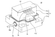
- FIG. 1 It is a perspective view of a thermal type mass flow sensor (the 1st sensor) concerning a 1st embodiment of the present invention.
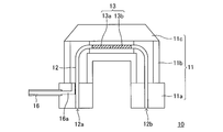
- A front view, (b) top view (perspective view), (c) bottom view of the first sensor, (d) sectional view by plane DD 'seen from left side, and (e) seen from the front It is a sectional view by plane EE '.
- plane EE ' It is a typical enlarged view of (e) of FIG.
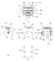
- the end on the opposite side of the exhaust hole 16a of the exhaust pipe 16 provided in the first sensor according to the second modification of the first embodiment of the present invention forms a sealing portion 16b, and the inner space of the cap 16c is concerned.
- the inert gas whose water content is reduced by the water reducing means for reducing the water contained in the inert gas is removed from the exhaust pipe.
- FIG. 10 is a schematic side view of the first flow meter observed from the direction of arrow A shown in FIG. 9;
- FIG. 10 is a schematic plan view (top view) of the first flow meter observed from the direction of arrow B shown in FIG. 9;
- It is a typical front view of the 1st flowmeter concerning modification 1 of a 3rd embodiment of the present invention observed from the direction which intersects perpendicularly with the axis of the flow path of the fluid provided in the base.
- FIG. 13 is a schematic side view of the first flow meter observed from the direction of arrow A shown in FIG. 12;
- FIG. 13 is a schematic plan view (top view) of the first flow meter observed from the direction of arrow B shown in FIG.
- FIG. 16 is a schematic side view of the first flow meter observed from the direction of arrow A shown in FIG. 15;
- FIG. 16 is a schematic plan view (top view) of the first flow meter observed from the direction of arrow B shown in FIG.
- first sensor thermal mass flow rate sensor
- the first sensor 10 comprises a sensor tube 12, a pair of sensor wires 13 (13 a and 13 b, only shown in FIG. 3) wound around the sensor tube 12, and at least a sensor wire 13. And a covering layer (not shown) covering a portion wound around the sensor tube 12 in the same manner as a general thermal mass flow sensor.
- the sensor tube 12 is inert to the fluid to be measured (for example, the process gas supplied into the chamber in the semiconductor manufacturing process) flowing therethrough, and the measurement condition (for example, mass flow rate of the fluid to be measured) It is a tubular member formed of a material that can withstand temperature, pressure, etc.).
- a steel pipe made of stainless steel for example, SUS316 material of Japanese Industrial Standard
- having an outer diameter of 0.6 mm and a thickness of 0.04 mm was used as the sensor tube 12.
- the sensor wire 13 is a heating element capable of heating the fluid to be measured flowing through the sensor tube 12 by heat generation by energization and a conductor capable of functioning as a resistance element whose electric resistance value changes according to the temperature. It is a linear member to be formed.
- a wire made of an iron-nickel alloy (iron 30%, nickel 70%) having a diameter of 35 ⁇ m was used as the sensor wire 13.
- the material constituting the covering layer is required to have a function as an electrical insulator, a function as an adhesive, and a function as a conductor of heat. Furthermore, it is preferable to form a thin covering layer on the surface of the sensor wire 13 and have a flexibility so as not to cause a crack when the sensor wire 13 after forming the covering layer is wound around the sensor tube 12. From these viewpoints, as a material which comprises a coating layer, organic materials, such as resin which has the outstanding heat resistance, such as polyamide imide and polyimide, are used, for example.
- a polyimide precursor N-methylpyrrolidone solution of polyimide acid (hereinafter sometimes referred to as “solution A”) is applied to the surface of the sensor wire 13, dried, and then baked. Then, a coating layer of polyimide having a thickness of 6.0 ⁇ m was formed. A coating layer may be provided on the surface of the sensor tube 12 for the purpose of, for example, further ensuring the insulation and adhesion between the sensor tube 12 and the sensor wire 13.
- the solution A is applied to the surface of the sensor tube 12 over a predetermined length, dried, and then baked to form a coating layer made of polyimide also on the surface of the sensor tube 12 Can.
- the sensor tube 12, the sensor wire 13 and the coating layer are housed in the internal space of the sealed container 11 sealed in an inert atmosphere for the purpose of suppressing the disappearance of the coating layer with use at high temperature.
- the sealed container 11 is constituted by the constituent members 11a, 11b and 11c.
- the materials constituting the component members 11a, 11b and 11c can be airtightly joined to each other by welding, for example, to form the closed container 11, and the measurement conditions of the mass flow rate of the fluid to be measured (for example, temperature and pressure) Etc.) are selected.
- a sensor base made of stainless steel for example, SUS316L material of Japanese Industrial Standard etc.
- a sensor case made of 42 alloy for example, a sensor case made of 42 alloy
- a lid made of 42 alloy are adopted as constituent members 11a, 11b and 11c, respectively.
- the airtight container 11 was comprised by joining by welding.
- inert atmosphere refers to an atmosphere that does not degrade the coating layer. Specifically, “inert atmosphere” refers to, for example, a state in which there is no or only a slight amount of an oxidizing gas such as oxygen in the internal space of the sealed container 11, an inert gas such as a noble gas. It refers to the state in which the internal space of the sealed container 11 is filled with gas, the vacuum state (including the extremely low pressure state), and the like.
- the sensor tube 12 is in airtight communication with the inlet 12 a and the outlet 12 b formed in the outer wall that defines the internal space of the sealed container 11.
- the inlet 12a and the outlet 12b may be formed in any of the components 11a, 11b and 11c. That is, the inlet 12a and the outlet 12b may be formed in any of the sensor base, the sensor case and the lid. Typically, the inlet 12a and the outlet 12b are formed in the sensor base.
- the opening on the bottom side (outside of the sealed container 11) of the two through holes formed in the component 11a which is a sensor base made of stainless steel flows It corresponds to the inlet 12a and the outlet 12b, respectively.
- the sensor tube 12 is made of a stainless steel pipe, in this example, the sensor tube 12 and the inlet 12a and the outlet 12b are joined by welding.
- the sensor tube 12 is disposed upstream and downstream of a bypass (not shown) provided in the flow path (not shown) of the fluid to be measured.
- the inlet 12a and the outlet 12b are respectively connected to the upstream and downstream sides of the bypass in the flow path of the fluid to be measured.
- the first sensor 10 is provided on the outer wall that defines the internal space of the sealed container 11, and both ends of the pair of sensor wires 13a and 13b are electrically connected to the external electrode 15 provided outside the sealed container 11.
- a hermetic connector 14 is provided to connect.
- power can be supplied to the pair of sensor wires 13a and 13b from a power source (not shown) provided outside the sealed container 11 through the external electrode 15.
- a predetermined current is caused to flow through the sensor wire 13 to generate heat, and the fluid to be measured (for example, flowing inside the sensor tube 12 as described above)
- the mass flow rate of the process gas supplied to the chamber in the semiconductor manufacturing process can be measured.
- a sensor circuit including a bridge circuit constituted by a pair of sensor wires 13a and 13b and other resistance elements can be configured to measure the mass flow rate of the fluid to be measured flowing through the sensor tube 12 as described above. .
- the hermetic connector 14 may be formed on any of the components 11a, 11b and 11c. That is, the hermetic connector 14 may be formed on any of the sensor base, the sensor case, and the lid. In the present embodiment, as shown in FIGS. 1 and 2, the hermetic connector 14 is formed on the component 11b which is a 42 alloy sensor case. The detailed configuration of the hermetic connector 14 is well known to those skilled in the art, and thus the description thereof is omitted. In the present example, Kovar (registered trademark) (iron / nickel / cobalt alloy manufactured by Westinghouse Co., Ltd.) plated with gold was used as a material for forming the external electrode 15.
- Kovar registered trademark
- the first sensor 10 is a pipe that airtightly communicates the internal space of the sealed container 11 with the outside through the exhaust hole 16a, which is a through hole formed in the outer wall that defines the internal space of the sealed container 11.
- the exhaust pipe 16 is further provided.
- the exhaust hole 16a may be formed in any of the component members 11a, 11b and 11c. That is, the exhaust hole 16a may be formed in any of the sensor base, the sensor case, and the lid. In the present embodiment, as shown in FIGS. 2 and 3, the exhaust hole 16 a is formed in the component 11 a which is a sensor base made of stainless steel.
- the exhaust pipe 16 is not only the measurement condition (for example, temperature and pressure, etc.) of the mass flow rate of the fluid to be measured, but also the inside and the outside of the pipe when discharging air from the internal space of the sealed container 11 as described in detail later. And a tubular member formed of a material capable of withstanding a pressure difference between the two.
- a steel pipe made of stainless steel for example, SUS316L material of Japanese Industrial Standard
- having an outer diameter of 2.0 mm and a thickness of 0.5 mm was used as the exhaust pipe 16.
- the end of the exhaust pipe 16 opposite to the exhaust hole 16 a is sealed by plastic deformation to form a sealing portion 16 b.
- the internal space of the exhaust pipe 16 in the sealing portion 16 b is closed, and the internal space of the sealed container 11 is shut off from the outside. That is, the closed container 11 is airtightly closed.
- the sealed portion 16 b is formed by crushing the exhaust pipe 16, the internal space of the exhaust pipe 16 is closed, and the internal space of the sealed container 11 is shut off from the outside.
- the specific method for plastically deforming the exhaust pipe 16 to form the sealing portion 16 b is not limited to the above.
- the exhaust pipe 16 is formed of a material capable of plastic deformation.
- the exhaust pipe 16 is formed of a metal such as, for example, an iron-based metal such as stainless steel described above.
- the material forming the exhaust pipe 16 has properties such that it is sealed by plastic deformation to require an excessive load when forming the sealing portion 16 b or not to cause an unintended breakage. From such a point of view, the material forming the exhaust pipe 16 has a hardness smaller than a predetermined hardness. Specifically, the material forming the exhaust pipe 16 preferably has a Vickers hardness of 180 or less, more preferably 150 or less. Such an exhaust pipe 16 can be obtained, for example, by annealing a stainless steel pipe having a desired shape and size at a predetermined temperature.
- the closed container 11 is configured by the three components 11a, 11b and 11c.
- the number of components of the closed container 11, the shapes of the individual components, and the like are not limited to the above. That is, the number of components forming the closed container 11 and the shape of each component can be variously changed according to the configuration of the target sensor.
- the inlet 12a, the outlet 12b, and the exhaust hole 16a are formed in the component 11a, and the hermetic connector 14 is formed in the component 11b.
- the arrangement of the inlet 12a and the outlet 12b, the exhaust hole 16a and the hermetic connector 14 is not limited to the above as long as the configuration capable of realizing the function as a thermal mass flow sensor can be achieved. That is, all of the inlet 12a, the outlet 12b, the exhaust hole 16a, and the hermetic connector 14 may be formed in one component or may be formed in different components.
- the sensor tube 12 around which the sensor wire 13 covered with the covering layer is wound is enclosed in the closed container 11 in an inert atmosphere. Therefore, the loss of the covering layer of the sensor wire 13 associated with the use at high temperature can be suppressed. Furthermore, according to the first sensor 10 having the above-described configuration, the closed container 11 can be obtained by welding the component members 11a to 11c under a normal atmosphere, not under a special environment such as a glove box, for example. It can be assembled. Therefore, the closed container 11 can be assembled easily and with high accuracy.
- the internal space of the sealed container 11 thus assembled is finally airtightly closed by sealing the exhaust pipe 16 communicating with the exhaust hole 16a by plastic deformation. Therefore, the closed container 11 can be airtightly closed not under a special environment such as a glove box but under a normal atmosphere. Furthermore, unlike the sealing by heating and melting the sealing material made of, for example, a solder-based material, it is possible to suppress the decrease in the airtightness of the sealed container 11 accompanying the use at high temperature.
- the deterioration of the coating layer of the sensor wire accompanying the use of the thermal mass flow rate sensor is caused without causing the increase of the manufacturing cost and / or the decrease of the processing accuracy of the closed container. Changes over time can be suppressed.
- the airtight container 11 when an inert atmosphere is achieved by vacuum, the airtight container 11 is required to have a higher degree of airtightness. Further, for example, even when the internal space of the sealed container 11 is filled with an inert gas and it is necessary to heat the first sensor 10 to a significantly high temperature at the time of flow rate measurement, higher air tightness is required. Ru.
- the sealing portion 16b may be further sealed by welding.
- the exhaust pipe 16 is formed of a weldable material.
- the exhaust pipe 16 is formed of a metal such as, for example, an iron-based metal such as stainless steel described above.
- the internal space of the sealed container 11 is further airtightly closed by the welding of the sealing portion 16b.
- the airtightness of the sealed container 11 can be further enhanced.
- the shape of the sealing portion 16b may be caused, for example, by residual stress of plastic deformation due to temperature rise accompanying welding. May at least partially return to the state before sealing, and the seal in the sealing portion 16b may be broken.
- the sealing portion 16 b is not welded, for example, when the first sensor 10 is heated to a significantly high temperature during flow rate measurement, the same problem may occur. That is, for example, at the time of flow rate measurement, welding, etc., there is a concern that the airtightness may be reduced due to the shape change of the sealing portion 16b due to the temperature rise.
- the first sensor 10 further includes a cap 16 c in which an internal space capable of accommodating the sealing portion 16 b and an opening is formed.
- the cap 16 c and the exhaust pipe 16 may be further sealed by welding in a state in which the sealing portion 16 b is inserted into the internal space of the cap 16 c through the opening.
- the cap 16 c including the sealing portion 16 b due to the plastic deformation of the exhaust pipe 16 is further sealed by being welded to the exhaust pipe 16.
- the sealing portion 16 b itself is not welded, it is possible to prevent a drop in air tightness due to a change in shape of the sealing portion 16 b due to a temperature rise accompanying the welding.
- the welding is further performed by welding the cap 16c and the exhaust pipe 16 as described above. Since it has stopped, the fall of the airtightness as the airtight container 11 whole can be prevented.
- the first method includes the first to fifth steps as described above. Each of the first to fifth steps will be described in detail below.
- the method of manufacturing the thermal mass flow sensor according to the present invention includes, for example, the first process or the like depending on the configuration of the thermal mass flow sensor to be manufactured and the specifications of the manufacturing equipment for which the manufacturing method is to be executed. It goes without saying that steps other than the fifth step can be further included.
- the first sensor 10 described above is implemented by sequentially executing the first to fifth steps as shown in the flowchart of FIG. The case of manufacturing by the first method is assumed. Therefore, each component of the first sensor 10 will be described with the same reference numeral as that of the first sensor 10 described above.
- step S01 First, in step S01, of the plurality of members constituting the sealed container 11, both ends of the inflow port 12a, the outflow port 12b, and the sensor tube 12 are provided to the first member which is the member in which the inflow port 12a and the outflow port 12b are formed.
- the sensor tube 12 on which the pair of sensor wires 13 (13a and 13b) are wound is welded so as to be in airtight communication with the portion.
- the inlet 12a and the outlet 12b are formed in the component 11a. Therefore, in the first sensor 10, the component 11a corresponds to the first member.
- step S02 of the plurality of members constituting the sealed container 11, both ends (13a and 13b) of the pair of sensor wires 13 are hermetically sealed on the second member which is the member provided with the hermetic connector 14. It electrically connects to the corresponding terminal (not shown) of the connector 14, respectively.
- the hermetic connector 14 is formed on the component 11b. Therefore, in the first sensor 10, the component 11b corresponds to the second member. Further, as described above, both ends of the pair of sensor wires 13 wound around the sensor tube 12 welded to the first member (constituent member 11a) are disposed on the inner side of the second member (constitutive member 11b) It is necessary to electrically connect to the terminals of the connector 14. In order to facilitate this operation, the upper side of the component 11b (the side opposite to the side facing the component 11a) is open. In addition, as described in detail later, the opening is closed by the component 11 c to form the closed container 11.
- a specific method for connecting both ends of the pair of sensor wires 13 to the corresponding terminals of the hermetic connector 14 is the manufacturing conditions of the first sensor 10 and the measurement conditions of the mass flow rate of the fluid to be measured (for example, temperature and pressure)
- the connection is not particularly limited as long as the connection can endure.
- both ends of the sensor wire 13 were connected by welding to the corresponding terminals of the hermetic connector 14.
- step S03 the third member, which is a member having the exhaust hole 16a formed of the plurality of members constituting the hermetic container 11, is in airtight communication with the internal space of the hermetic container 11 via the exhaust hole 16a. As such, the exhaust pipe 16 is welded.
- the exhaust hole 16a is formed in the component 11a. Therefore, in the first sensor 10, the component 11a corresponds to the third member. That is, in the first sensor 10, the component 11a corresponds to both the first member and the third member.
- the first to third members may be any of a plurality of constituent members constituting the sealed container 11.
- one of the plurality of components constituting the closed container 11 may correspond to all of the first to third members, or a plurality of components constituting the closed container 11
- the first to third members may correspond to different constituent members among them.
- step S04 a plurality of members constituting the closed container 11 are welded to each other to form the closed container 11. That is, in the fourth step, a plurality of members including the first member, the second member, and the third member described above are welded to each other to form the sealed container 11.
- the closed container 11 is welded by mutually welding a component 11c which is a lid made of 42 alloy.
- the specific method for welding the respective constituent members to form the closed container 11 as described above is not particularly limited.
- a welding method such as the above-described resistance welding method or laser welding method can be employed.
- a part of part (joining part) facing component 11a (sensor base) of component 11b (sensor case) protrudes ing.
- the outline of the bonding portion includes the region where the external electrode 15 provided outside the component 11b is present, A protrusion 11b 'is formed on a part of the joint portion.
- a laser welding method is adopted as a specific method for forming the closed container 11 by welding the respective constituent members.
- a laser beam is irradiated to the bonding portion from the upper side (that is, the component 11 b side) in FIG. 1. Therefore, it is difficult to sufficiently bond the component 11a and the component 11b because the laser beam to be irradiated to the bonding portion interferes with the external electrode 15 when the above projection 11b 'is not formed. And the external electrode 15 may be damaged.
- Step 5 Therefore, after the air (atmosphere) is discharged from the internal space of the sealed container 11 by a pressure reducing pump or the like (not shown) via the exhaust pipe 16 in step S05, the end of the exhaust pipe 16 on the opposite side to the exhaust hole 16a. The portion is sealed by plastic deformation to form a sealed portion 16b.
- plastic deformation for example, crushing, bending, cutting, threading and the like can be mentioned.
- plastic deformation of the exhaust pipe 16 can be generated using, for example, tools such as pliers, nippers and pliers and processing machines such as a press.
- the sealing portion 16 b is not necessarily located at the end of the exhaust pipe 16 opposite to the exhaust hole 16 a from the start of plastic deformation of the exhaust pipe 16.
- the sealing portion 16b is formed at the end of the exhaust pipe 16 opposite to the exhaust hole 16a. May be formed.
- the execution order of each process included in the method of manufacturing the thermal mass flow sensor according to the present invention is not limited to the flowchart of FIG. 6 and the above description.
- the exhaust pipe 16 is plastically deformed after the internal space of the sealed container 11 is airtightly closed except for the exhaust hole 16a and the exhaust pipe 16 formed in the third member (constituent member 11a)
- the order of execution of the respective steps is not particularly limited as long as the fifth step of sealing to form the sealing portion 16 b is performed.
- steps S01 to S04 surrounded by a broken line in the flowchart of FIG. 6 are not particularly limited in the execution order of the steps, as long as it is possible to obtain a thermal mass flow sensor having a target configuration.
- the sensor tube 12 around which the sensor wire 13 covered with the covering layer is wound is sealed in the closed container 11 in an inert atmosphere (in this example, in a vacuum state)
- an inert atmosphere in this example, in a vacuum state
- the sealed container 11 can be assembled by welding the component members 11a to 11c under a normal atmosphere, not under a special environment such as a glove box. Therefore, the closed container 11 can be assembled easily and with high accuracy.
- the internal space of the sealed container 11 assembled as described above is finally airtightly closed by sealing the exhaust pipe 16 communicating with the exhaust hole 16a by plastic deformation. Therefore, the closed container 11 can be airtightly closed not under a special environment such as a glove box but under a normal atmosphere. Furthermore, unlike the sealing by heating and melting the sealing material made of, for example, a solder-based material, it is possible to suppress the decrease in the airtightness of the sealed container 11 accompanying the use at high temperature.
- the internal space of the sealed container 11 when the internal space of the sealed container 11 is in a vacuum state, the pressure difference between the internal space of the sealed container 11 and the outside is very large, and the joint between the sealing member 16 b and the components of the sealed container 11 is Depending on the airtightness, there is a concern that air or the like from the surrounding atmosphere enters the internal space of the sealed container 11 during the subsequent use period of the first sensor 10, and the internal space of the sealed container 11 is not an inert atmosphere. In order to reduce such a concern, for example, it is desirable to form the sealing portion 16 b in a state where the internal space of the sealed container 11 is filled with an inert gas.
- the air is discharged from the internal space of the sealed container 11 by the pressure reducing pump or the like through the exhaust pipe 16 in the fifth step, the air is deactivated in the internal space of the sealed container 11 through the exhaust pipe 16 After sealing the gas, the end of the exhaust pipe 16 opposite to the exhaust hole 16a may be sealed by plastic deformation to form the sealing portion 16b.
- the sealing portion 16 b is formed in a state in which the internal space of the sealed container 11 is filled with the inert gas.
- the pressure difference between the internal space of the closed container 11 and the outside can be reduced. Therefore, it is possible to reduce the concern that air or the like from the surrounding atmosphere enters the internal space of the sealed container 11 during the subsequent use period of the first sensor 10 and the internal space of the sealed container 11 is not inert atmosphere.
- the inert gas with which the internal space of the sealed container 11 is filled contains water as described above, for example, the coating layer of the sensor wire 13 is used along with the use of the first sensor 10 (for example, hydrolysis etc. And the sensitivity of the first sensor 10 may change. Therefore, after the air is exhausted from the internal space of the sealed container 11 through the exhaust pipe 16 in the fifth step, the inert gas whose moisture content is reduced by the moisture reducing means for reducing the moisture contained in the inert gas May be enclosed in the internal space of the sealed container 11 via the exhaust pipe 16.
- a piping system in which the exhaust line 20 and the sealing line 30 are connected to the exhaust pipe 16 of the first sensor 10 via the branch point B is prepared.
- a pressure reducing pump (vacuum pump) 21 is connected to an end of the exhaust line 20 opposite to the branch point B, and an on-off valve 22 is interposed between the pressure reducing pump and the branch point B.
- an inert gas source 31 (for example, a cylinder or the like) serving as a supply source of an inert gas (for example, nitrogen, argon or the like) is connected to the end of the sealing line 30 opposite to the branch point B
- a regulator 32, an on-off valve 33, a moisture reducing means 34, and an on-off valve 35 are interposed in the order from the inert gas source 31 to the branch point B.
- an inert gas source 31 for example, a cylinder or the like
- an inert gas for example, nitrogen, argon or the like
- an inert gas for example, nitrogen, argon or the like
- an inert gas for example, nitrogen, argon or the like
- an inert gas for example, nitrogen, argon or the like
- an inert gas for example, nitrogen, argon or the like
- an inert gas for example, nitrogen, argon or the like
- an inert gas for example, nitrogen, argon or the like
- the pressure reducing pump 21 is operated in a state where the on-off valve 22 is opened and the on-off valve 35 is closed, via the exhaust pipe 16 and the exhaust line 20.
- the air is exhausted from the internal space of the closed container 11 (not shown) (see the open arrow in the figure).
- the on-off valve 22 is closed, the on-off valve 33 and the on-off valve 35 are opened, and the inert gas is sealed from the inert gas source 31 into the internal space of the sealed container 11 through the sealing line 30 and the exhaust pipe 16 See the solid arrows in the figure.)
- the inert gas flowing from the inert gas source 31 to the sealed container 11 passes through the moisture reducing means 34 interposed in the sealing line 30, the moisture contained in the inert gas is reduced, and the inert gas is not The water content in the active gas is reduced.
- the moisture reduction means 34 reduces the moisture. Therefore, for example, the problem that the coating layer of the sensor wire 13 is deteriorated due to (for example, hydrolysis etc.) or the sensitivity of the first sensor 10 changes with the use of the first sensor 10 can be reduced.
- the internal space of the sealed container 11 is further airtightly closed by the welding of the sealing portion 16b.
- the airtightness of the sealed container 11 can be further enhanced.
- the cap 16 c including the sealing portion 16 b due to the plastic deformation of the exhaust pipe 16 is further sealed by being welded to the exhaust pipe 16.
- the sealing portion 16 b itself is not welded, it is possible to prevent a drop in air tightness due to a change in shape of the sealing portion 16 b due to a temperature rise accompanying the welding.
- the welding is further performed by welding the cap 16c and the exhaust pipe 16 as described above. Since it has stopped, the fall of the airtightness as the airtight container 11 whole can be prevented.
- the first method may further include an air tightness test step of checking the air tightness of the sealed container 11.
- a method of detecting the presence or absence of leakage of a specific component gas from the inside of the sealed container is adopted for the sealed container according to the prior art having no exhaust pipe. It is common to do. Specifically, for example, a detection gas (tracer gas) containing a specific component such as hydrogen (H 2 ), argon (Ar) or helium (He) is filled in the inside of the closed container, and the closed container is used as a chamber. It is left inside for a predetermined period under predetermined conditions.
- a detection gas traceer gas
- a specific component such as hydrogen (H 2 ), argon (Ar) or helium (He)
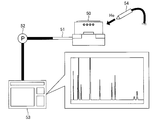
- a vacuum method (spray method) using a helium leak detector as shown in FIG. 8 is cited. be able to.
- the detection gas He
- the portion to which the detection gas is supplied is specified as a defective portion having insufficient airtightness.
- the thermal mass flow sensor according to the present invention including the first sensor 10 is provided with the exhaust pipe 16 communicating with the internal space of the sealed container 11. Therefore, if the exhaust pipe 16 is not sealed in the above-described fifth step, the airtightness test by the vacuum method spraying method as described above can be performed without requiring special processing.
- a specific detection gas is locally supplied to the outer surface of the sealed container 11 before the fifth step is performed, via the exhaust pipe 16 (for example, by a pressure reduction pump or the like).
- Airtightness test step of specifying the place where the detection gas is supplied when the detection gas is detected in the gas discharged from the internal space of the sealed container 11 as a defective place having insufficient airtightness Can further be included.
- the airtightness test by the above-mentioned vacuum method spraying method can be performed without requiring special processing. Accordingly, the airtightness test of the closed container can be performed on the total number of thermal mass flow sensors manufactured by the first method while reducing the increase in manufacturing cost.
- the mass spectrometer 53 is used as a detection means for the detection gas (specific component contained therein), but it goes without saying that, instead of the mass spectrometer 53, for example, A relatively simple detection means such as an analysis tube having a detection ability specialized for a specific component can be employed.
- the first method can perform the above-described fifth step at a temperature higher than room temperature.
- air is exhausted from the internal space of the sealed container 11 through the exhaust pipe 16 (see, for example, the open arrow in FIG. 7). Therefore, even if a small amount of water is attached to the inner wall of the sealed container 11 or a material such as a resin constituting the coating layer of the sensor wire 13 adsorbs water, the fifth step is performed at room temperature As compared with the above, water is more effectively reduced from the internal space of the sealed container 11. As a result, it is possible to reduce, for example, the problem that the coating layer of the sensor wire 13 is deteriorated due to (for example, hydrolysis etc.) or the sensitivity of the first sensor 10 changes with the use of the first sensor 10 .
- the fifth step when air is exhausted from the internal space of the sealed container 11 through the exhaust pipe 16 and then an inert gas is sealed in the internal space through the exhaust pipe 16, it is not possible at a temperature higher than room temperature. Active gas is enclosed in the internal space. Therefore, when the first sensor 10 is used at a temperature higher than room temperature, the temperature when the inert gas is filled and the temperature when the first sensor 10 is used are lower than when the fifth step is performed at room temperature. The difference between is smaller. As a result, the pressure in the internal space when using the first sensor 10 can be prevented from becoming significantly higher than the atmospheric pressure.
- the higher the temperature when performing the fifth step the more effectively the moisture is reduced from the internal space of the sealed container 11.
- the temperature when executing the fifth step is excessively high, for example, the resin etc. constituting the coating layer of the sensor wire 13 may deteriorate or the stainless steel constituting the closed container 11 may discolor, etc. It may lead to problems.
- the temperature when performing the fifth step is a temperature higher than room temperature and 200 ° C. or less.
- the invention also relates to a thermal mass flowmeter using the thermal mass flow sensor according to the invention.
- a thermal mass flow meter (hereinafter sometimes referred to as “first flow meter”) according to a third embodiment of the present invention will be described with reference to the drawings.
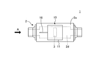
- FIG. 9 is a schematic front view of the first flow meter observed from the direction orthogonal to the axis of the fluid flow path provided in the base.
- FIG. 10 is a schematic side view of the first flow meter observed from the direction of arrow A shown in FIG.
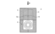
- FIG. 11 is a schematic plan view (top view) of the first flow meter observed from the direction of arrow B shown in FIG.
- FIGS. 9 to 11 for the purpose of facilitating the understanding of the configuration of the first flow meter 1, the flow path 2d provided inside, the bypass 3, the sensor tube 12, the sensor wires 13a and 13b, etc. Is represented by a dashed line. However, in FIG. 10 and FIG. 11, the sensor tube 12 and the sensor wires 13a and 13b are omitted.
- the first flow meter 1 has one installation surface 2a, and is provided between the base 2 on which the fluid flow path 2d is provided and the flow path 2d. It has a bypass 3, a first sensor 10, and a sensor circuit (not shown) including a bridge circuit constituted by sensor wires 13 a and 13 b included in the first sensor 10 and other resistive elements (not shown). .
- the sensor tube 12 is configured to branch from the flow path 2 d on the upstream side of the bypass 3 and bypass the outside of the installation surface 2 a and then join the flow path 2 d on the downstream side of the bypass 3.
- the first flow meter 1 employs the first sensor 10 as a thermal mass flow sensor.
- the deterioration of the coating layer of the sensor wire accompanying the use of the thermal flowmeter does not result in an increase in the manufacturing cost and / or a decrease in the processing accuracy of the closed container. Changes over time can be suppressed.
- thermal mass flow rate sensor constituting the thermal mass flow meter according to the present invention is not limited to the first sensor 10, and various thermal mass flow rate sensors according to the present invention can be used. .
- the first sensor 10 is disposed on the installation surface 2a of the base 2 in which the flow path 2d is provided. That is, the sensor tube 12 is provided so as to protrude from the base 2. Therefore, the first sensor 10 including the sensor tube 12 is likely to be cooled under the influence of the ambient temperature around the first flow meter 1. As a result, it becomes difficult to maintain the temperature of the gas flowing through the sensor tube 12 at a high temperature, which may lead to problems such as condensation of the gas inside the sensor tube 12, for example.
- the first flowmeter 1 according to the first modification of the third embodiment of the present invention further includes a member (heat transfer block) for conducting heat from the base 2 to the closed container 11 of the first sensor 10 It is also good.
- FIG. 12 is a schematic front view of the first flowmeter according to the first modification of the third embodiment of the present invention which is observed from the direction orthogonal to the axis of the flow path of the fluid provided in the base.
- FIG. 13 is a schematic side view of the first flow meter observed from the direction of arrow A shown in FIG.
- FIG. 14 is a schematic plan view (top view) of the first flow meter observed from the direction of arrow B shown in FIG.
- FIG. 12 to FIG. 14 for the purpose of facilitating the understanding of the configuration of the first flow meter 1, the flow path 2d provided inside, the bypass 3, the first sensor 10, the closed container 11, the exhaust pipe 16 (parts thereof) and a through hole 5a and the like formed in the heat transfer block 5 (described later) for inserting the exhaust pipe 16 are shown by broken lines.
- the sensor tube 12 and the sensor wires 13a and 13b are omitted.
- the hatched portions in FIG. 12 to FIG. 14 with downward slanting lines illustrate the embodiment of the heat transfer block 5.
- the first flowmeter 1 is a heat transfer provided in contact with the installation surface 2a of the base 2 at a position adjacent to the closed container 11 and formed of a heat transfer material.
- the block 5 is further included.
- the bottom surface of the heat transfer block 5 is in surface contact with the installation surface 2 a, and at least one side surface of the heat transfer block 5 is in surface contact with the side surface of the sealed container 11.
- the heat transfer block 5 is in surface contact with the side surface and the upper surface (top surface) of the closed container 11 and the installation surface 2 a of the base 2.
- surface contact means that a position at which one part and another part are in contact is a flat surface, and both are in contact without any gap.
- the heat transfer block 5 When the surface of the heat transfer block 5 makes surface contact with both the installation surface 2 a of the base 2 and the side surface (and the top surface) of the closed container 11, the heat transfer block 5 is interposed from the installation surface 2 a of the base Heat is conducted without delay, and the temperature difference between the base 2 and the closed vessel 11 is reduced. As a result, the temperature difference between the flow path 2 d formed inside the base 2 and the sensor tube 12 housed inside the closed container 11 is also reduced.
- the heat transfer block 5 is preferably made of a material having as high a thermal conductivity as possible. Accordingly, the heat transfer block 5 is formed of a heat transfer material.
- a heat transfer material refers to a material having high thermal conductivity (i.e., a good conductor of heat), which has at least a thermal conductivity higher than stainless steel.
- copper or aluminum or an alloy containing copper or aluminum can be used.
- the aluminum-containing alloy that can be suitably used for the heat transfer block 5 include, for example, industrial pure aluminum excellent in thermal conductivity (in the international aluminum alloy name series of 1000) and strength and workability. Examples of the excellent Al-Mg-based alloy (the international aluminum alloy name is 5000 series) and the like can be mentioned.
- the heat transfer block 5 needs to be provided adjacent to the closed vessel 11 in contact with the installation surface 2 a of the base 2. Thereby, heat can be efficiently conducted from the installation surface 2 a toward the sealed container 11.
- the heat transfer block 5 is preferably installed so as to cover the entire outer surface (except for the bottom surface in contact with the installation surface 2 a) of the sealed container 11.
- the embodiment of the heat transfer block 5 is not particularly limited as long as heat can be conducted from the mounting surface 2a of the base to the closed vessel 11 through the heat transfer block 5 without any problem.
- the heat transfer block 5 can not be installed so as to cover the entire outer surface of the closed container 11 due to the positional relationship with other parts constituting the thermal mass flow meter, etc. Even if a portion is exposed, the heat transfer block 5 may be provided adjacent to the other portion of the outer surface of the closed vessel 11 and in contact with the other portion and the installation surface 2 a of the base 2.
- the shape of the heat transfer block 5 can be designed in any shape.
- the heat transfer block 5 can be provided so as to be divisible into a plurality of parts for the convenience of assembly.
- the heat transfer block 5 illustrated in FIGS. 12 to 14 is composed of two parts, and can be assembled and fixed so as to sandwich the sealed container 11.
- a through hole for inserting the exhaust pipe 16 as illustrated in FIGS. 12 to 14. 5 a can be formed in the heat transfer block 5.
- the heat conduction between the base 2 and (the closed container 11 of) the first sensor 10 is promoted by the heat transfer block 5, it is affected by the environmental temperature around the first flow meter 1. It becomes difficult for the first sensor 10 to be cooled. As a result, the temperature of the gas flowing through the sensor tube 12 is maintained at a desired temperature when, for example, the piping system is heated and held so that the process gas does not condense in the piping when using a coagulable gas as the process gas. As a result, problems such as condensation of gas inside the sensor tube 12 can be reduced.
- the first flow meter 1 may further include a heat transfer promoting member which is a member for further promoting heat transfer from the base 2 to the closed vessel 11 and / or the heat transfer block 5.
- a heat transfer promotion member a heat transfer sheet etc. which were provided in contact with the side of base 2 and the side of heat transfer block 5 can be mentioned, for example.
- a material which forms such a heat-transfer sheet the metal material which forms the heat-transfer block 5 mentioned above, a graphite, a silicone type material, etc. can be mentioned, for example.
- the first flow meter 1 may further include a heat insulating material which is a member for reducing the heat radiation from at least one of the base 2, the sealed container 11 and the heat transfer block 5.
- a heat insulating material which is a member for reducing the heat radiation from at least one of the base 2, the sealed container 11 and the heat transfer block 5.
- positioned so that the base 2, the airtight container 11, and at least one part of the exposed surface of the heat-transfer block 5 may be mentioned can be mentioned, for example.
- a material which forms such a heat insulation sheet what hardened glass fiber with a binder, etc. can be mentioned, for example.
- FIG. 15 is a schematic front view of the first flowmeter according to the second modification of the third embodiment of the present invention, which is observed from the direction orthogonal to the axis of the flow path of the fluid provided in the base.
- FIG. 16 is a schematic side view of the first flow meter observed from the direction of arrow A shown in FIG.
- FIG. 17 is a schematic plan view (top view) of the first flow meter observed from the direction of arrow B shown in FIG.
- FIGS. 15 to 17 the flow path 2 d provided inside, the bypass 3, (part of the exhaust pipe 16), the heat transfer, for the purpose of facilitating the understanding of the configuration of the first flow meter 1.
- the first sensor 10 in FIGS. 15 to 17, the first sensor 10, the closed container 11 and the like are omitted.
- the heat generating body 8b (or the cooling body 8c) was abbreviate
- the hatched portion of FIG. 15 to FIG. 17 with the upper right hatching illustrates the embodiment of the temperature control block 8.
- the arrangement and shape of the temperature adjustment block 8 are It is not particularly limited. Further, although the temperature control block 8 is configured to be divided into a plurality of members in the examples shown in FIGS. 15 to 17, for example, the temperature control block 8 is configured in a range not accompanied by inconvenience in assembly and the like. The shape and number of members to be used can be determined appropriately. When the temperature control block 8 is disposed to cover the surface of the closed vessel 11 from which the exhaust pipe 16 protrudes, as in the case of the heat transfer block 5, as illustrated in FIGS. A through hole 8 a for inserting 16 can be formed in the temperature control block 8.
- the temperature control block 8 as well as the heat transfer block 5 is preferably also made of a material having as high a thermal conductivity as possible. Accordingly, the temperature control block 8 is also formed by the heat transfer material.
- the heat transfer material which can be suitably used for the temperature control block 8, in addition to the metal material which forms the heat transfer block 5 mentioned above, silicon rubber, ceramics, etc. can be mentioned.
- the heating element 8b is an element or device that generates thermal energy, and as a specific example thereof, a cartridge heater including a nichrome wire can be mentioned, for example.
- the cooling body 8c is an element or device which absorbs thermal energy, and as a specific example thereof, for example, a Peltier element or the like can be mentioned.
- a specific example of the temperature control block 8 is, for example, a bar-like member including nichrome wire in a plate or block member formed of aluminum alloy.
- a plate heater or the like in which the heating element 8b is provided can be suitably used.
- the temperature control block 11 for example, a plate-like or block-like member formed of an aluminum alloy 8c inserted and / or attached, rubber cooler having cooling body 8c in plate-like or block-like member formed of silicone rubber, cooling into plate-like or block-like member formed of ceramics
- a plate cooler or the like provided with the body 8c can be suitably used.
- the base 2 and / or the heat transfer block 5 can be actively heated or cooled by the temperature adjustment block 8, the temperature of the first sensor 10 is maintained regardless of the ambient temperature around the first flow meter 1. It is even easier to maintain the temperature at the desired temperature. As a result, for example, problems such as condensation and deterioration of gas inside the sensor tube 12 can be reduced.
- the first flow meter 1 is a heat transfer promoting member which is a member for further promoting heat conduction from the temperature adjustment block 8 to the base 2 and / or the closed vessel 11 and / or the heat transfer block 5. It may further have.
- a heat transfer promoting member for example, it is provided in contact with any surface of the temperature control block 8 and any surface of the base 2 and / or the sealed container 11 and / or the heat transfer block 5 And the like.
- a material which forms such a heat-transfer sheet the metal material which forms the heat-transfer block 5 mentioned above, a graphite, a silicone type material, etc. can be mentioned, for example.
- the first flow meter 1 may further include a heat insulating material which is a member for reducing the heat radiation from at least one of the temperature adjustment block 8, the base 2, the closed container 11 and the heat transfer block 5.
- a heat insulating material which is a member for reducing the heat radiation from at least one of the temperature adjustment block 8, the base 2, the closed container 11 and the heat transfer block 5.
- positioned so that the surface of at least one part of the temperature control block 8, the base 2, the airtight container 11, and the heat transfer block 5 may be mentioned, for example .
- a material which forms such a heat insulation sheet what hardened glass fiber with a binder, etc. can be mentioned, for example.
- the first flowmeter 1 according to the second modification of the third embodiment described above includes the base 2 and / or the base 2 and / or the temperature control block 8 provided with the heating element 8 b and / or the cooling body 8 c in addition to the heat transfer block 5.
- the heat transfer block 5 can be actively heated or cooled. This makes it easier to maintain the temperature of the first sensor 10 at a desired temperature regardless of the ambient temperature around the first flow meter 1. For example, problems such as condensation and deterioration of gas inside the sensor tube 12 Can be reduced.
- the heating element 8b and / or the temperature adjustment block 8 is provided according to the relationship between the temperature of the first sensor 10 and the target temperature.
- the operation and stop of the cooling body 8c are switched.
- the first sensor 10 includes the exhaust pipe 16 which is a pipe that airtightly communicates the internal space of the sealed container 11 with the outside.
- the exhaust pipe 16 withstands not only the measurement conditions (for example, temperature and pressure, etc.) of the mass flow rate of the fluid to be measured but also the pressure difference between the inside and the outside of the pipe when air is exhausted from the internal space of the sealed container 11 It is formed by the material to be obtained.
- a metal pipe such as, for example, a stainless steel pipe is used as the exhaust pipe 16. Therefore, the exhaust pipe 16 can also act as a heat conduction path for conducting heat between the internal space of the sealed container 11 and the outside.
- a transitional temperature change of the temperature control block 8 accompanying switching of the operation and stop of the heating element 8b and / or the cooling body 8c is transmitted to the internal space of the sealed container 11 through the exhaust pipe 16, (1)
- the detection result of the mass flow rate by the sensor 10 may be affected. This phenomenon occurs, for example, that the position of the exhaust hole 16a (corresponding to the end of the exhaust pipe 16 on the side of the internal space of the sealed container 11) in the first sensor 10 is closer to one of the pair of sensor wires 13a and 13b, This is more remarkable when the exhaust hole 16a is in an asymmetrical position with respect to the pair of sensor wires 13a and 13b in the heat conduction path in the first sensor 10.
- the position where the exhaust hole is symmetrical to the pair of sensor wires in the heat conduction path in the thermal mass flow sensor It is in.
- heat is similarly transmitted to the pair of sensor wires 13 a and 13 b from the exhaust hole 16 a corresponding to the end portion of the exhaust pipe 16 on the inner space side of the sealed container 11. Configured to communicate.
- the first sensor 10 is configured such that the exhaust pipe 16 and the exhaust hole 16a are on the symmetry axis of the pair of sensor wires 13a and 13b.
- the exhaust holes 16a can be disposed at “symmetrical positions with respect to the pair of sensor wires 13a and 13b”.
- the exhaust pipe 16 is disposed on the left side surface of the component 11a of the sealed container 11.
- the exhaust pipe 16 is located at the center of the back surface of the component 11a of the sealed container 11.
- An exhaust pipe 16 is provided.
- the arrangement of the exhaust pipe 16 and the exhaust hole 16a is not particularly limited as long as heat can be transmitted from the exhaust hole 16a to each of the pair of sensor wires 13a and 13b in the same manner.
- the exhaust pipe 16 may not be on the symmetry axis.
- the heat conducted through the exhaust pipe 16 and the exhaust hole 16a is transmitted to the pair of sensor wires 13a and 13b in the same manner.
- a transitional temperature change of the temperature control block 8 accompanying switching of the operation and stop of the heating element 8b and / or the cooling body 8c is transmitted to the internal space of the sealed container 11 through the exhaust pipe 16, Problems such as affecting the detection result of mass flow rate by the single sensor 10 are reduced.
- the heat transfer block is obtained by spatially separating the heat transfer block 5 and / or the temperature control block 8 and the exhaust pipe 16.
- the heat conduction between the temperature control block 8 and the exhaust pipe 16 is reduced.
- the through hole 5 a and the through hole 8 a through which the exhaust pipe 16 is inserted are respectively formed in the heat transfer block 5 and the temperature control block 8.
- the shortest distance between the outer surface of the exhaust pipe 16 and the inner surfaces of the through holes 5a and the through holes 8a is 1 mm or more.
- the first flowmeter 1 according to the fifth modification of the third embodiment of the present invention is the first flowmeter 1 according to the fourth modification of the third embodiment described above, and the outer surface of the exhaust pipe 16 and the through hole 5a And the heat insulating material is filled between the inner surfaces of the through holes 8a.
- the heat conduction between the heat transfer block 5 and / or the temperature control block 8 and the exhaust pipe 16 can be further reduced by the heat insulating material.
- the heat conduction between the internal space of the sealed container 11 and the outside via the exhaust pipe 16 can be further reduced, the above-mentioned problems can be more reliably reduced.
- the thermal mass flow meter according to the present invention (the flow meter of the present invention) comprises a flow control valve, an actuator for increasing or decreasing the opening of the flow control valve, and the flow meter of the present invention.
- a thermal mass flow control device can be configured by combining with a control device that controls the opening degree of the flow control valve using the actuator so that the flow rate of the detected fluid approaches the target value. Accordingly, the present invention relates not only to the above-described thermal mass flow sensor and thermal mass flow meter, but also to a thermal mass flow controller using the flow meter of the present invention.
Landscapes
- Physics & Mathematics (AREA)
- Fluid Mechanics (AREA)
- General Physics & Mathematics (AREA)
- Measuring Volume Flow (AREA)
Abstract
Description
密閉容器を構成する複数の部材のうち、流入口及び流出口が形成された部材である第1部材に、流入口及び流出口とセンサチューブの両端部とが気密に連通するように、一対のセンサワイヤが巻き付けられたセンサチューブを溶接する。
密閉容器を構成する複数の部材のうち、ハーメチックコネクタが設けられた部材である第2部材に、一対のセンサワイヤのそれぞれの両端をハーメチックコネクタの対応する端子にそれぞれ電気的に接続する。
密閉容器を構成する複数の部材のうち、排気孔が形成された部材である第3部材に、排気孔を介して密閉容器の内部空間と気密に連通するように、排気管を溶接する。
密閉容器を構成する複数の部材を互いに溶接して密閉容器を形成する。
排気管を介して(例えば、減圧ポンプ等によって)内部空間から空気を排出した後、排気管の排気孔とは反対側の端部を塑性変形によって封止して封止部を形成する。
以下、図面を参照しながら本発明の第1実施形態に係る熱式質量流量センサ(以降、「第1センサ」と称呼される場合がある)について説明する。
図1乃至図4に示すように、第1センサ10は、センサチューブ12と、センサチューブ12に巻き付けられた一対のセンサワイヤ13(13a及び13b、図3においてのみ図示)と、少なくともセンサワイヤ13のセンサチューブ12に巻き付けられた部分を覆う被覆層(図示せず)と、を備える点において、一般的な熱式質量流量センサと同様の構成を有する。
第1センサ10においては、被覆層に覆われたセンサワイヤ13が巻き付けられたセンサチューブ12が不活性雰囲気にある密閉容器11の中に封入されている。従って、高温における使用に伴うセンサワイヤ13の被覆層の消失を抑制することができる。更に、上記のような構成を有する第1センサ10によれば、例えばグローブボックス等の特殊な環境下ではなく、通常の大気雰囲気下において構成部材11a乃至11cを溶接することによって、密閉容器11を組み立てることができる。従って、密閉容器11を容易且つ高精度に組み立てることができる。
上述したように、第1センサ10においては、排気管16の排気孔16aとは反対側の端部が塑性変形によって封止されて封止部16bを形成することにより、不活性雰囲気にある密閉容器11の内部空間が気密に閉じられる。しかしながら、排気管16の塑性変形のみによる封止によって達成される密閉容器11の気密性では不十分な場合がある。
ところが、上記のように排気管16の塑性変形による封止部16bを溶接によって更に封止する場合、溶接に伴う温度上昇により、例えば塑性変形の残留応力に起因して、封止部16bの形状が封止前の状態に少なくとも部分的に戻り、封止部16bにおける封止が破れる場合がある。また、封止部16bが溶接されていない場合、例えば、流量測定時に第1センサ10を著しく高い温度にまで加熱すると同様の問題が生ずる虞がある。即ち、例えば流量測定時及び溶接時等において、温度上昇による封止部16bの形状変化に起因する気密性の低下が懸念される。
以下、図面を参照しながら本発明の第2実施形態に係る熱式質量流量センサの製造方法(以降、「第1方法」と称呼される場合がある)について説明する。
先ず、ステップS01において、密閉容器11を構成する複数の部材のうち、流入口12a及び流出口12bが形成された部材である第1部材に、流入口12a及び流出口12bとセンサチューブ12の両端部とが気密に連通するように、一対のセンサワイヤ13(13a及び13b)が巻き付けられたセンサチューブ12を溶接する。
次に、ステップS02において、密閉容器11を構成する複数の部材のうち、ハーメチックコネクタ14が設けられた部材である第2部材に、一対のセンサワイヤ13のそれぞれ(13a及び13b)の両端をハーメチックコネクタ14の対応する端子(図示せず)にそれぞれ電気的に接続する。
更に、ステップS03において、密閉容器11を構成する複数の部材のうち、排気孔16aが形成された部材である第3部材に、排気孔16aを介して密閉容器11の内部空間と気密に連通するように、排気管16を溶接する。
次に、ステップS04において、密閉容器11を構成する複数の部材を互いに溶接して密閉容器11を形成する。即ち、第4工程においては、上述した第1部材、第2部材及び第3部材を含む複数の部材を互いに溶接して密閉容器11を形成する。本例においては、ステンレス鋼製のセンサベースである構成部材11a及び42アロイ製のセンサケースである構成部材11bに加えて42アロイ製の蓋である構成部材11cを互いに溶接して密閉容器11を形成する。
そこで、ステップS05において、排気管16を介して減圧ポンプ等(図示せず)によって密閉容器11の内部空間から空気(大気)を排出した後、排気管16の排気孔16aとは反対側の端部を塑性変形によって封止して封止部16bを形成する。
以上のように、第1方法によれば、被覆層に覆われたセンサワイヤ13が巻き付けられたセンサチューブ12を不活性雰囲気(本例においては真空状態)にある密閉容器11の中に封入することにより高温における使用に伴うセンサワイヤ13の被覆層の消失を抑制することができる第1センサ10を容易且つ高精度に製造することができる。具体的には、第1方法によれば、例えばグローブボックス等の特殊な環境下ではなく、通常の大気雰囲気下において構成部材11a乃至11cを溶接することによって密閉容器11を組み立てることができる。従って、密閉容器11を容易且つ高精度に組み立てることができる。
上述した第1方法に含まれる第5工程においては、排気管16を介して減圧ポンプ等によって密閉容器11の内部空間から空気(大気)を排出した後、排気管16の排気孔16aとは反対側の端部を塑性変形によって封止して封止部16bを形成した。これにより、密閉容器11の内部空間は不活性雰囲気としての真空状態となる。しかしながら、密閉容器11の内部空間が真空状態にある場合、密閉容器11の内部空間と外部との間の圧力差が非常に大きく、封止部16b及び密閉容器11の構成部材間の接合部の気密性によっては、その後の第1センサ10の使用期間中に密閉容器11の内部空間に周囲雰囲気から空気等が進入し、密閉容器11の内部空間が不活性雰囲気ではなくなる懸念がある。このような懸念を低減するためには、例えば、密閉容器11の内部空間が不活性ガスによって充填されている状態において封止部16bを形成することが望ましい。
前述したように、排気管16の塑性変形のみによる封止によって達成される密閉容器11の気密性では不十分な場合がある。そこで、上記第5工程において、封止部16bを形成した後、当該封止部16bを溶接によって更に封止してもよい。
ところが、前述したように、例えば流量測定時及び溶接時等において、温度上昇による封止部16bの形状変化に起因する気密性の低下が懸念される場合がある。このような場合は、上記第5工程において、封止部16bを形成した後、当該封止部16bを収容可能な内部空間及び開口部が形成されたキャップ16cの内部空間に開口部を通して当該封止部16bが挿入された状態において、上記キャップ16cと上記排気管16とを溶接によって更に封止してもよい。
ところで、第1方法によって製造される第1センサ10において、センサチューブ12に巻き付けられたセンサワイヤ13を覆う被覆層が高温における第1センサ10の使用に伴って消失することを確実に抑制するためには、密閉容器11の気密性が高いことが必要である。そこで、第1方法は、密閉容器11の気密性を調べる気密性テスト工程を更に含むことができる。
ところで、前述したように第1センサ10の密閉容器11の内部空間に充填される不活性ガスが水分を含んでいる場合のみならず、例えば、密閉容器11の内壁に微量の水分が付着していたり、センサワイヤ13の被覆層を構成する樹脂等の材料が水分を吸着していたりする場合においても、例えば、第1センサ10の使用に伴ってセンサワイヤ13の被覆層が(例えば加水分解等)により劣化したり、第1センサ10の感度が変化したりする問題に繋がる虞がある。
前述したように、本発明は、本発明に係る熱式質量流量センサを用いる熱式質量流量計にも関する。以下、図面を参照しながら本発明の第3実施形態に係る熱式質量流量計(以降、「第1流量計」と称呼される場合がある)について説明する。
ところで、例えば半導体の製造プロセス等においては、ある種の液体材料の気化ガスや固体材料の昇華ガスのように、常温で凝結(液体化又は固体化)し易いガス(以降、「凝結性ガス」と称される場合がある。)をプロセスガスとして使用する場合がある。このような場合、半導体の製造プロセスにおいてチャンバー内に供給されるプロセスガスが配管内で凝結してしまわないように、チャンバーに至るまでの全ての配管系を臨界温度以上の温度に加熱保持しなければならない。この配管系には、上述したベース2の内部に設けられた流体の流路2dも含まれる。
上述した第3実施形態の変形例1に係る第1流量計1においては、ベース2と第1センサ10(の密閉容器11)との間の熱伝導を伝熱ブロック5によって促進することにより、第1流量計1の周囲の環境温度の影響を受けて第1センサ10の温度を所望の温度に維持することを容易にしている。即ち、伝熱ブロック5は、自ら能動的に熱を発生するものではなく、ベース2の熱を密閉容器11に伝える受動的な役割を担っている。
上述した第3実施形態の変形例2に係る第1流量計1は、伝熱ブロック5に加えて、発熱体8b及び/又は冷却体8cを備えた温度調節ブロック8により、ベース2及び/又は伝熱ブロック5を能動的に加熱又は冷却することができる。これにより、第1流量計1の周囲の環境温度に拘わらず第1センサ10の温度を所望の温度に維持することを更に容易にし、例えばセンサチューブ12の内部におけるガスの凝結及び劣化等の問題を低減することができる。
上述した第3実施形態の変形例3においては、排気管16及び排気孔16aを介して伝導される熱が一対のセンサワイヤ13a及び13bのそれぞれに対して同じように伝わるようにすることにより、発熱体8b及び/又は冷却体8cの作動と停止との切り替えに伴う温度調節ブロック8の過渡的な温度変化が第1センサ10による質量流量の検出結果に影響を及ぼす等の問題を低減した。しかしながら、伝熱ブロック5及び/又は温度調節ブロック8と排気管16との間における熱伝導を低減することができれば、上記問題を根本的に低減することができる筈である。
本発明の第3実施形態の変形例5に係る第1流量計1は、上述した第3実施形態の変形例4に係る第1流量計1であって、排気管16の外面と貫通孔5a及び貫通孔8aの内面との間に断熱材が充填されている。
Claims (17)
- 密閉容器と、前記密閉容器の内部空間を画定する外壁に形成された流入口及び流出口と気密に連通し且つ前記密閉容器の前記内部空間に収容されたセンサチューブと、前記センサチューブに巻き付けられた一対のセンサワイヤと、少なくとも前記センサワイヤの前記センサチューブに巻き付けられた部分を覆う被覆層と、前記外壁に設けられて前記一対のセンサワイヤのそれぞれの両端を前記密閉容器の外部に設けられた外部電極に電気的に接続するハーメチックコネクタと、を備え、
前記密閉容器の前記内部空間は不活性雰囲気に密閉されている、
熱式質量流量センサであって、
前記外壁に形成された貫通孔である排気孔を介して前記密閉容器の前記内部空間と外部とを気密に連通する管である排気管を更に備え、
前記排気管の前記排気孔とは反対側の端部が塑性変形によって封止されて封止部を形成している、
熱式質量流量センサ。 - 請求項1に記載の熱式質量流量センサであって、
前記封止部が溶接によって更に封止されている、
熱式質量流量センサ。 - 請求項1に記載の熱式質量流量センサであって、
前記封止部を収容可能な内部空間及び開口部が形成されたキャップを更に備え、
前記キャップの前記内部空間に前記開口部を通して前記封止部が挿入された状態において前記キャップと前記排気管とが溶接によって更に封止されている、
熱式質量流量センサ。 - 密閉容器と、前記密閉容器の内部空間を画定する外壁に形成された流入口及び流出口と気密に連通し且つ前記密閉容器の前記内部空間に収容されたセンサチューブと、前記センサチューブに巻き付けられた一対のセンサワイヤと、少なくとも前記センサワイヤの前記センサチューブに巻き付けられた部分を覆う被覆層と、前記外壁に設けられて前記一対のセンサワイヤのそれぞれの両端を前記密閉容器の外部に設けられた外部電極に電気的に接続するハーメチックコネクタと、を備え、
前記密閉容器の前記内部空間は不活性雰囲気に密閉されており、
前記外壁に形成された貫通孔である排気孔を介して前記密閉容器の前記内部空間と外部とを気密に連通する管である排気管を更に備え、
前記排気管の前記排気孔とは反対側の端部が塑性変形によって封止されて封止部を形成している、
熱式質量流量センサの製造方法であって、
前記密閉容器を構成する複数の部材のうち、前記流入口及び前記流出口が形成された部材である第1部材に、前記流入口及び前記流出口と前記センサチューブの両端部とが気密に連通するように、前記一対のセンサワイヤが巻き付けられた前記センサチューブを溶接する第1工程と、
前記密閉容器を構成する前記複数の部材のうち、前記ハーメチックコネクタが設けられた部材である第2部材に、前記一対のセンサワイヤのそれぞれの両端を前記ハーメチックコネクタの対応する端子にそれぞれ電気的に接続する第2工程と、
前記密閉容器を構成する前記複数の部材のうち、前記排気孔が形成された部材である第3部材に、前記排気孔を介して前記密閉容器の前記内部空間と気密に連通するように、前記排気管を溶接する第3工程と、
前記密閉容器を構成する前記複数の部材を互いに溶接して前記密閉容器を形成する第4工程と、
前記排気管を介して前記内部空間から空気を排出した後、前記排気管の前記排気孔とは反対側の端部を塑性変形によって封止して前記封止部を形成する第5工程と、
を含む、
熱式質量流量センサの製造方法。 - 請求項4に記載の熱式質量流量センサの製造方法であって、
前記第5工程において、前記排気管を介して前記内部空間から空気を排出した後、前記排気管を介して前記内部空間に不活性ガスを封入した後、前記排気管の前記排気孔とは反対側の端部を塑性変形によって封止して前記封止部を形成する、
熱式質量流量センサの製造方法。 - 請求項5に記載の熱式質量流量センサの製造方法であって、
前記第5工程において、前記排気管を介して前記内部空間から空気を排出した後、前記不活性ガスに含まれる水分を低減する水分低減手段によって水分の含有率を下げた前記不活性ガスを、前記排気管を介して、前記内部空間に封入する、
熱式質量流量センサの製造方法。 - 請求項4乃至請求項6の何れか1項に記載の熱式質量流量センサの製造方法であって、
前記第5工程において、前記封止部を形成した後、前記封止部を溶接によって更に封止する、
熱式質量流量センサの製造方法。 - 請求項4乃至請求項6の何れか1項に記載の熱式質量流量センサの製造方法であって、
前記第5工程において、前記封止部を形成した後、前記封止部を収容可能な内部空間及び開口部が形成されたキャップの前記内部空間に前記開口部を通して前記封止部が挿入された状態において前記キャップと前記排気管とを溶接によって更に封止する、
熱式質量流量センサの製造方法。 - 請求項4乃至請求項8の何れか1項に記載の熱式質量流量センサの製造方法であって、
前記第5工程を実行する前に、前記密閉容器の外表面に特定の検知用ガスを局所的に供給しつつ、前記排気管を介して前記内部空間から排出される気体中に前記検知用ガスが検出されたときに前記検知用ガスが供給されていた箇所を気密性が不十分な不良箇所として特定する気密性テスト工程を更に含む、
熱式質量流量センサの製造方法。 - 請求項4乃至請求項9の何れか1項に記載の熱式質量流量センサの製造方法であって、
室温よりも高い温度において前記第5工程を実行する、
熱式質量流量センサの製造方法。 - 請求項10に記載の熱式質量流量センサの製造方法であって、
室温よりも高く且つ200℃以下の温度において前記第5工程を実行する、
熱式質量流量センサの製造方法。 - 一の設置面を有し、内部に流体の流路が設けられたベースと、
前記流路の中間に設けられたバイパスと、
請求項1乃至請求項3の何れか1項に記載の熱式質量流量センサと、
前記センサワイヤ及び他の抵抗素子によって構成されたブリッジ回路を含むセンサ回路と、
を有し、
前記センサチューブは、前記バイパスの上流側において前記流路から分岐し前記設置面の外側を迂回した後に前記バイパスの下流側において前記流路に合流するように構成されている、
熱式質量流量計。 - 請求項12に記載の熱式質量流量計であって、
前記設置面に接して、前記密閉容器と隣り合う位置に設けられた、伝熱材料によって形成された伝熱ブロックを更に有し、
前記伝熱ブロックの底面と前記設置面とは面接触をしており、
前記伝熱ブロックの少なくとも一の側面と前記密閉容器の側面とは面接触をしている、
熱式質量流量計。 - 請求項13に記載の熱式質量流量計であって、
前記ベース及び前記伝熱ブロックの少なくとも一方の側面に接して設けられた温度調節ブロックを更に有し、
前記温度調節ブロックは、伝熱材料によって形成されており、且つ、前記温度調節ブロックを加熱する発熱体及び/又は前記温度調節ブロックを冷却する冷却体を有する、
熱式質量流量計。 - 請求項14に記載の熱式質量流量計であって、
前記熱式質量流量センサにおける熱伝導経路において、前記一対のセンサワイヤに対して前記排気孔が対称な位置にある、
熱式質量流量計。 - 請求項14又は請求項15に記載の熱式質量流量計であって、
前記排気管が挿通する貫通孔が前記伝熱ブロック及び前記温度調節ブロックに形成されており、
前記排気管の外面と前記貫通孔の内面との間の最短距離が1mm以上である、
熱式質量流量計。 - 請求項16に記載の熱式質量流量計であって、
前記排気管の外面と前記貫通孔の内面との間に断熱材が充填されている、
熱式質量流量計。
Priority Applications (4)
| Application Number | Priority Date | Filing Date | Title |
|---|---|---|---|
| KR1020187025855A KR102403432B1 (ko) | 2016-03-11 | 2017-02-17 | 열식 질량 유량 센서, 당해 열식 질량 유량 센서의 제조 방법, 및 당해 열식 질량 유량 센서를 사용하는 열식 질량 유량계 |
| US16/080,767 US10859417B2 (en) | 2016-03-11 | 2017-02-17 | Thermal mass flow sensor, method for manufacturing the thermal mass flow sensor, and thermal mass flow meter using the thermal mass flow sensor |
| CN201780016648.XA CN108779996B (zh) | 2016-03-11 | 2017-02-17 | 热式质量流量传感器及其制造方法以及热式质量流量计 |
| JP2018504323A JP6769478B2 (ja) | 2016-03-11 | 2017-02-17 | 熱式質量流量センサ、当該熱式質量流量センサの製造方法、及び当該熱式質量流量センサを用いる熱式質量流量計 |
Applications Claiming Priority (2)
| Application Number | Priority Date | Filing Date | Title |
|---|---|---|---|
| JP2016048578 | 2016-03-11 | ||
| JP2016-048578 | 2016-03-11 |
Publications (1)
| Publication Number | Publication Date |
|---|---|
| WO2017154513A1 true WO2017154513A1 (ja) | 2017-09-14 |
Family
ID=59790383
Family Applications (1)
| Application Number | Title | Priority Date | Filing Date |
|---|---|---|---|
| PCT/JP2017/005816 Ceased WO2017154513A1 (ja) | 2016-03-11 | 2017-02-17 | 熱式質量流量センサ、当該熱式質量流量センサの製造方法、及び当該熱式質量流量センサを用いる熱式質量流量計 |
Country Status (5)
| Country | Link |
|---|---|
| US (1) | US10859417B2 (ja) |
| JP (1) | JP6769478B2 (ja) |
| KR (1) | KR102403432B1 (ja) |
| CN (1) | CN108779996B (ja) |
| WO (1) | WO2017154513A1 (ja) |
Cited By (1)
| Publication number | Priority date | Publication date | Assignee | Title |
|---|---|---|---|---|
| WO2026052928A1 (en) * | 2024-09-09 | 2026-03-12 | Lwf Uk Limited | A mounting arrangement and a sensing arrangement for a fluid pipe |
Families Citing this family (7)
| Publication number | Priority date | Publication date | Assignee | Title |
|---|---|---|---|---|
| EP3979843B1 (en) * | 2019-06-28 | 2023-11-01 | Philip Morris Products S.A. | System and method for testing a heating system for use in an aerosol |
| WO2021095492A1 (ja) * | 2019-11-15 | 2021-05-20 | 株式会社堀場エステック | 流体抵抗素子及び流体制御装置 |
| CN111707698B (zh) * | 2020-07-16 | 2021-04-13 | 西安交通大学 | 一种流量与温度协同交变加热方式下高温煅烧反应特性的实验装置及测试方法 |
| NL2026167B1 (en) * | 2020-07-30 | 2022-04-08 | Berkin Bv | Thermal-type flow sensor with a thermally conductive frame element in the form of a printed circuit board (PCB) |
| CN114993397A (zh) * | 2022-05-28 | 2022-09-02 | 广州市唯量工控技术有限公司 | 高温型热式mems流量计 |
| KR102841659B1 (ko) | 2022-10-17 | 2025-08-01 | 한국기계연구원 | 유량 센서가 통합된 약물 주입기 |
| CN119178461B (zh) * | 2024-11-22 | 2025-03-07 | 山西创芯光电科技有限公司 | 一种抗干扰红外探测芯片封装结构 |
Citations (8)
| Publication number | Priority date | Publication date | Assignee | Title |
|---|---|---|---|---|
| JPS581181U (ja) * | 1981-06-26 | 1983-01-06 | 富士電機株式会社 | ガス封入式放射線検出器 |
| JPS6287825A (ja) * | 1985-10-01 | 1987-04-22 | バリアン・アソシエイツ・インコ−ポレイテツド | ガス漏れ検知のための方法及び装置 |
| JPH01100433A (ja) * | 1987-10-13 | 1989-04-18 | Mitsubishi Motors Corp | 加熱式リークテスト方法 |
| JPH02196472A (ja) * | 1989-01-25 | 1990-08-03 | Fuji Electric Co Ltd | 半導体圧力センサ |
| JPH03167425A (ja) * | 1989-11-27 | 1991-07-19 | Stec Kk | 質量流量計 |
| JP2004020418A (ja) * | 2002-06-18 | 2004-01-22 | Japan Atom Energy Res Inst | 放射性ヨウ素の核変換用ターゲット |
| WO2015041255A1 (ja) * | 2013-09-18 | 2015-03-26 | 日立金属株式会社 | 流量センサ、それを用いた質量流量計及び質量流量制御装置並びに流量センサの製造方法 |
| WO2015141437A1 (ja) * | 2014-03-20 | 2015-09-24 | 日立金属株式会社 | 熱式質量流量計及びこれを用いた質量流量制御装置 |
Family Cites Families (7)
| Publication number | Priority date | Publication date | Assignee | Title |
|---|---|---|---|---|
| JPS5694597A (en) | 1979-12-28 | 1981-07-31 | Fujitsu Ltd | Memory data control system |
| JPH0979880A (ja) | 1995-09-08 | 1997-03-28 | Mitsui Mining & Smelting Co Ltd | 流量センサ装置 |
| US6125695A (en) * | 1997-10-13 | 2000-10-03 | Teledyne Brown Engineering, Inc. | Method and apparatus for measuring a fluid |
| US7157836B2 (en) | 2004-10-19 | 2007-01-02 | Seiko Epson Corporation | Piezoelectric device |
| NL1032007C2 (nl) * | 2006-06-14 | 2007-12-17 | Berkin Bv | Stromingssensor van het thermische type. |
| US7971480B2 (en) * | 2008-10-13 | 2011-07-05 | Hitachi Metals, Ltd. | Mass flow controller having a first pair of thermal sensing elements opposing a second pair of thermal sensing elements |
| CN104700506B (zh) * | 2015-03-31 | 2017-10-31 | 成都秦川物联网科技股份有限公司 | 安全切断型远控智能质量流量燃气表及其管理系统 |
-
2017
- 2017-02-17 CN CN201780016648.XA patent/CN108779996B/zh active Active
- 2017-02-17 WO PCT/JP2017/005816 patent/WO2017154513A1/ja not_active Ceased
- 2017-02-17 KR KR1020187025855A patent/KR102403432B1/ko active Active
- 2017-02-17 JP JP2018504323A patent/JP6769478B2/ja active Active
- 2017-02-17 US US16/080,767 patent/US10859417B2/en active Active
Patent Citations (8)
| Publication number | Priority date | Publication date | Assignee | Title |
|---|---|---|---|---|
| JPS581181U (ja) * | 1981-06-26 | 1983-01-06 | 富士電機株式会社 | ガス封入式放射線検出器 |
| JPS6287825A (ja) * | 1985-10-01 | 1987-04-22 | バリアン・アソシエイツ・インコ−ポレイテツド | ガス漏れ検知のための方法及び装置 |
| JPH01100433A (ja) * | 1987-10-13 | 1989-04-18 | Mitsubishi Motors Corp | 加熱式リークテスト方法 |
| JPH02196472A (ja) * | 1989-01-25 | 1990-08-03 | Fuji Electric Co Ltd | 半導体圧力センサ |
| JPH03167425A (ja) * | 1989-11-27 | 1991-07-19 | Stec Kk | 質量流量計 |
| JP2004020418A (ja) * | 2002-06-18 | 2004-01-22 | Japan Atom Energy Res Inst | 放射性ヨウ素の核変換用ターゲット |
| WO2015041255A1 (ja) * | 2013-09-18 | 2015-03-26 | 日立金属株式会社 | 流量センサ、それを用いた質量流量計及び質量流量制御装置並びに流量センサの製造方法 |
| WO2015141437A1 (ja) * | 2014-03-20 | 2015-09-24 | 日立金属株式会社 | 熱式質量流量計及びこれを用いた質量流量制御装置 |
Cited By (1)
| Publication number | Priority date | Publication date | Assignee | Title |
|---|---|---|---|---|
| WO2026052928A1 (en) * | 2024-09-09 | 2026-03-12 | Lwf Uk Limited | A mounting arrangement and a sensing arrangement for a fluid pipe |
Also Published As
| Publication number | Publication date |
|---|---|
| KR20180122344A (ko) | 2018-11-12 |
| JPWO2017154513A1 (ja) | 2019-01-10 |
| CN108779996A (zh) | 2018-11-09 |
| US20190178693A1 (en) | 2019-06-13 |
| JP6769478B2 (ja) | 2020-10-14 |
| KR102403432B1 (ko) | 2022-05-30 |
| CN108779996B (zh) | 2020-09-04 |
| US10859417B2 (en) | 2020-12-08 |
Similar Documents
| Publication | Publication Date | Title |
|---|---|---|
| JP6769478B2 (ja) | 熱式質量流量センサ、当該熱式質量流量センサの製造方法、及び当該熱式質量流量センサを用いる熱式質量流量計 | |
| US10468575B2 (en) | Thermoelectric module | |
| JP4901350B2 (ja) | 熱電変換装置及びその製造方法 | |
| CN110672171A (zh) | 热式空气流量测定装置 | |
| JPWO2010095367A1 (ja) | 真空封止パッケージ、真空封止パッケージを有するプリント回路基板、電子機器、及び真空封止パッケージの製造方法 | |
| CN1937273A (zh) | 热电装置及其制造方法 | |
| US10260978B2 (en) | Pressure detection unit and pressure sensor using the same | |
| CN102522343B (zh) | 一种微器件真空封装排气装置及方法 | |
| US12553751B2 (en) | Sensor assembly and methods of manufacturing thereof | |
| JP2015102490A (ja) | 圧力センサーの検査装置 | |
| US11137307B2 (en) | Pressure sensor | |
| CN103245710A (zh) | 用于确定有待分析的流体的组成部分的浓度的传感器以及方法 | |
| CN119660672A (zh) | 一种高真空mems器件封装工艺 | |
| CN102576977B (zh) | 半导体激光器模块 | |
| CN216484743U (zh) | 一种带封装台的结露系统及露点仪 | |
| US20200355568A1 (en) | Pressure transducer including kovar integrated packages | |
| JP2002013994A (ja) | 圧力センサ | |
| JPS5863826A (ja) | 半導体圧力変換器 | |
| CN218098045U (zh) | 红外热成像传感器及其吸气剂封装组件 | |
| JP2007212197A (ja) | センサの取付構造及びフローセンサの取付構造 | |
| JP2023048378A (ja) | ガスセンサ装置 | |
| US7101736B2 (en) | Method of assembling a semiconductor component and apparatus therefor | |
| JP2022186139A (ja) | 熱電変換パッケージ用封止材、及び、熱電変換パッケージ | |
| CN116667133A (zh) | 一种大功率激光器同轴封装基座的制作方法 | |
| JP2006132853A (ja) | 熱輸送装置の製造方法、熱輸送装置及び電子機器 |
Legal Events
| Date | Code | Title | Description |
|---|---|---|---|
| WWE | Wipo information: entry into national phase |
Ref document number: 2018504323 Country of ref document: JP |
|
| ENP | Entry into the national phase |
Ref document number: 20187025855 Country of ref document: KR Kind code of ref document: A |
|
| NENP | Non-entry into the national phase |
Ref country code: DE |
|
| 121 | Ep: the epo has been informed by wipo that ep was designated in this application |
Ref document number: 17762856 Country of ref document: EP Kind code of ref document: A1 |
|
| 122 | Ep: pct application non-entry in european phase |
Ref document number: 17762856 Country of ref document: EP Kind code of ref document: A1 |