WO2017154471A1 - 横断判定装置 - Google Patents
横断判定装置 Download PDFInfo
- Publication number
- WO2017154471A1 WO2017154471A1 PCT/JP2017/005189 JP2017005189W WO2017154471A1 WO 2017154471 A1 WO2017154471 A1 WO 2017154471A1 JP 2017005189 W JP2017005189 W JP 2017005189W WO 2017154471 A1 WO2017154471 A1 WO 2017154471A1
- Authority
- WO
- WIPO (PCT)
- Prior art keywords
- crossing
- yaw rate
- host vehicle
- speed
- unit
- Prior art date
- Legal status (The legal status is an assumption and is not a legal conclusion. Google has not performed a legal analysis and makes no representation as to the accuracy of the status listed.)
- Ceased
Links
Images


Classifications
-
- B—PERFORMING OPERATIONS; TRANSPORTING
- B60—VEHICLES IN GENERAL
- B60W—CONJOINT CONTROL OF VEHICLE SUB-UNITS OF DIFFERENT TYPE OR DIFFERENT FUNCTION; CONTROL SYSTEMS SPECIALLY ADAPTED FOR HYBRID VEHICLES; ROAD VEHICLE DRIVE CONTROL SYSTEMS FOR PURPOSES NOT RELATED TO THE CONTROL OF A PARTICULAR SUB-UNIT
- B60W30/00—Purposes of road vehicle drive control systems not related to the control of a particular sub-unit, e.g. of systems using conjoint control of vehicle sub-units
- B60W30/08—Active safety systems predicting or avoiding probable or impending collision or attempting to minimise its consequences
- B60W30/095—Predicting travel path or likelihood of collision
- B60W30/0956—Predicting travel path or likelihood of collision the prediction being responsive to traffic or environmental parameters
-
- B—PERFORMING OPERATIONS; TRANSPORTING
- B60—VEHICLES IN GENERAL
- B60W—CONJOINT CONTROL OF VEHICLE SUB-UNITS OF DIFFERENT TYPE OR DIFFERENT FUNCTION; CONTROL SYSTEMS SPECIALLY ADAPTED FOR HYBRID VEHICLES; ROAD VEHICLE DRIVE CONTROL SYSTEMS FOR PURPOSES NOT RELATED TO THE CONTROL OF A PARTICULAR SUB-UNIT
- B60W30/00—Purposes of road vehicle drive control systems not related to the control of a particular sub-unit, e.g. of systems using conjoint control of vehicle sub-units
- B60W30/08—Active safety systems predicting or avoiding probable or impending collision or attempting to minimise its consequences
- B60W30/095—Predicting travel path or likelihood of collision
- B60W30/0953—Predicting travel path or likelihood of collision the prediction being responsive to vehicle dynamic parameters
-
- B—PERFORMING OPERATIONS; TRANSPORTING
- B60—VEHICLES IN GENERAL
- B60W—CONJOINT CONTROL OF VEHICLE SUB-UNITS OF DIFFERENT TYPE OR DIFFERENT FUNCTION; CONTROL SYSTEMS SPECIALLY ADAPTED FOR HYBRID VEHICLES; ROAD VEHICLE DRIVE CONTROL SYSTEMS FOR PURPOSES NOT RELATED TO THE CONTROL OF A PARTICULAR SUB-UNIT
- B60W40/00—Estimation or calculation of non-directly measurable driving parameters for road vehicle drive control systems not related to the control of a particular sub unit, e.g. by using mathematical models
- B60W40/02—Estimation or calculation of non-directly measurable driving parameters for road vehicle drive control systems not related to the control of a particular sub unit, e.g. by using mathematical models related to ambient conditions
- B60W40/04—Traffic conditions
-
- B—PERFORMING OPERATIONS; TRANSPORTING
- B60—VEHICLES IN GENERAL
- B60W—CONJOINT CONTROL OF VEHICLE SUB-UNITS OF DIFFERENT TYPE OR DIFFERENT FUNCTION; CONTROL SYSTEMS SPECIALLY ADAPTED FOR HYBRID VEHICLES; ROAD VEHICLE DRIVE CONTROL SYSTEMS FOR PURPOSES NOT RELATED TO THE CONTROL OF A PARTICULAR SUB-UNIT
- B60W40/00—Estimation or calculation of non-directly measurable driving parameters for road vehicle drive control systems not related to the control of a particular sub unit, e.g. by using mathematical models
- B60W40/10—Estimation or calculation of non-directly measurable driving parameters for road vehicle drive control systems not related to the control of a particular sub unit, e.g. by using mathematical models related to vehicle motion
- B60W40/114—Yaw movement
-
- B—PERFORMING OPERATIONS; TRANSPORTING
- B60—VEHICLES IN GENERAL
- B60W—CONJOINT CONTROL OF VEHICLE SUB-UNITS OF DIFFERENT TYPE OR DIFFERENT FUNCTION; CONTROL SYSTEMS SPECIALLY ADAPTED FOR HYBRID VEHICLES; ROAD VEHICLE DRIVE CONTROL SYSTEMS FOR PURPOSES NOT RELATED TO THE CONTROL OF A PARTICULAR SUB-UNIT
- B60W60/00—Drive control systems specially adapted for autonomous road vehicles
- B60W60/001—Planning or execution of driving tasks
- B60W60/0015—Planning or execution of driving tasks specially adapted for safety
-
- B—PERFORMING OPERATIONS; TRANSPORTING
- B60—VEHICLES IN GENERAL
- B60W—CONJOINT CONTROL OF VEHICLE SUB-UNITS OF DIFFERENT TYPE OR DIFFERENT FUNCTION; CONTROL SYSTEMS SPECIALLY ADAPTED FOR HYBRID VEHICLES; ROAD VEHICLE DRIVE CONTROL SYSTEMS FOR PURPOSES NOT RELATED TO THE CONTROL OF A PARTICULAR SUB-UNIT
- B60W60/00—Drive control systems specially adapted for autonomous road vehicles
- B60W60/001—Planning or execution of driving tasks
- B60W60/0027—Planning or execution of driving tasks using trajectory prediction for other traffic participants
- B60W60/00274—Planning or execution of driving tasks using trajectory prediction for other traffic participants considering possible movement changes
-
- G—PHYSICS
- G06—COMPUTING OR CALCULATING; COUNTING
- G06V—IMAGE OR VIDEO RECOGNITION OR UNDERSTANDING
- G06V20/00—Scenes; Scene-specific elements
- G06V20/50—Context or environment of the image
- G06V20/56—Context or environment of the image exterior to a vehicle by using sensors mounted on the vehicle
- G06V20/58—Recognition of moving objects or obstacles, e.g. vehicles or pedestrians; Recognition of traffic objects, e.g. traffic signs, traffic lights or roads
-
- G—PHYSICS
- G08—SIGNALLING
- G08G—TRAFFIC CONTROL SYSTEMS
- G08G1/00—Traffic control systems for road vehicles
- G08G1/16—Anti-collision systems
- G08G1/166—Anti-collision systems for active traffic, e.g. moving vehicles, pedestrians, bikes
-
- B—PERFORMING OPERATIONS; TRANSPORTING
- B60—VEHICLES IN GENERAL
- B60W—CONJOINT CONTROL OF VEHICLE SUB-UNITS OF DIFFERENT TYPE OR DIFFERENT FUNCTION; CONTROL SYSTEMS SPECIALLY ADAPTED FOR HYBRID VEHICLES; ROAD VEHICLE DRIVE CONTROL SYSTEMS FOR PURPOSES NOT RELATED TO THE CONTROL OF A PARTICULAR SUB-UNIT
- B60W2520/00—Input parameters relating to overall vehicle dynamics
- B60W2520/10—Longitudinal speed
-
- B—PERFORMING OPERATIONS; TRANSPORTING
- B60—VEHICLES IN GENERAL
- B60W—CONJOINT CONTROL OF VEHICLE SUB-UNITS OF DIFFERENT TYPE OR DIFFERENT FUNCTION; CONTROL SYSTEMS SPECIALLY ADAPTED FOR HYBRID VEHICLES; ROAD VEHICLE DRIVE CONTROL SYSTEMS FOR PURPOSES NOT RELATED TO THE CONTROL OF A PARTICULAR SUB-UNIT
- B60W2520/00—Input parameters relating to overall vehicle dynamics
- B60W2520/14—Yaw
-
- B—PERFORMING OPERATIONS; TRANSPORTING
- B60—VEHICLES IN GENERAL
- B60W—CONJOINT CONTROL OF VEHICLE SUB-UNITS OF DIFFERENT TYPE OR DIFFERENT FUNCTION; CONTROL SYSTEMS SPECIALLY ADAPTED FOR HYBRID VEHICLES; ROAD VEHICLE DRIVE CONTROL SYSTEMS FOR PURPOSES NOT RELATED TO THE CONTROL OF A PARTICULAR SUB-UNIT
- B60W2554/00—Input parameters relating to objects
- B60W2554/40—Dynamic objects, e.g. animals, windblown objects
- B60W2554/404—Characteristics
- B60W2554/4042—Longitudinal speed
Definitions
- the present disclosure relates to a crossing determination device that is mounted on a vehicle and determines whether an object crosses the course of the vehicle.
- a vehicle is being equipped with a driving support device that avoids a collision accident caused by an object entering from the lateral direction toward the course of the host vehicle. is there.
- a PCS system Pre-crash safety system
- Patent Document 1 it is determined whether or not an object is going to cross the front of the host vehicle based on the amount of movement of the object in the direction crossing the course of the host vehicle. As a result, it is possible to determine the possibility of a collision only on an object that is about to cross the front of the host vehicle.
- the present disclosure has been made in order to solve the above-described problem, and a main purpose of the present disclosure is to detect an object in a scene where the traveling state of the host vehicle affects the detection state of the object in a direction crossing the course of the host vehicle. It is an object of the present invention to provide a crossing determination apparatus capable of suppressing erroneous determination of crossing determination.
- the present disclosure relates to a crossing determination device that detects an object that moves in a direction intersecting with a path of the host vehicle, and detects the current path of the host vehicle by the object detection unit.
- a crossing speed calculation unit that calculates a crossing speed that is a speed at which the object crosses, and the crossing speed calculated by the crossing speed calculation unit is higher than a predetermined speed, so that the object is a course of the host vehicle.
- a yaw rate detection unit that detects the yaw rate of the host vehicle.
- the crossing determination unit is configured to detect the object based on the yaw rate detected by the yaw rate detection unit. The crossing speed or the predetermined speed is corrected.
- the crossing speed or the predetermined speed of the object is corrected by the crossing determination unit based on the yaw rate of the host vehicle detected by the yaw rate detection unit.
- FIG. 1 is a schematic configuration diagram of a driving support device according to the present embodiment.
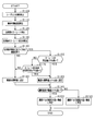
- FIG. 2 is a control flowchart executed by the detection ECU according to this embodiment.
- FIG. 3 is a control flowchart executed by a detection ECU according to another example.
- This driving support control functions as a PCS system (Pre-crash safety system) that performs control to avoid collision with an object or reduce collision damage.
- the driving support device 100 also functions as a crossing determination device according to the present embodiment.
- the driving support device 100 includes a detection ECU 10, a radar device 21, a yaw rate sensor (corresponding to a yaw rate detection unit) 22, and a steering angle sensor 23.
- the radar device 21 is, for example, a known millimeter wave radar that uses a high frequency signal in the millimeter wave band as a transmission wave.
- the radar device 21 is provided at the front end portion of the host vehicle and can detect an area within a predetermined detection angle. The position of the object within the detection range is detected. Specifically, an exploration wave is transmitted at a predetermined period, and a reflected wave is received by a plurality of antennas. The distance to the object is calculated from the transmission time of the exploration wave and the reception time of the reflected wave. Further, the relative speed (specifically, the relative speed in the traveling direction of the vehicle) is calculated from the frequency of the reflected wave reflected by the object, which has changed due to the Doppler effect.
- the azimuth of the object is calculated from the phase difference of the reflected waves received by the plurality of antennas. If the position and orientation of the object can be calculated, the relative position (lateral position) of the object with respect to the host vehicle can be specified. Therefore, the radar device 21 corresponds to an object detection unit and a crossing speed calculation unit. The radar device 21 performs transmission of the exploration wave, reception of the reflected wave, calculation of the reflection position and relative velocity at predetermined intervals, and transmits the calculated reflection position and relative velocity to the detection ECU 10.
- the radar device 21 is connected to the detection ECU 10.
- the detection ECU 10 is a computer that includes a CPU 11, a RAM 12, a ROM 13, an I / O, and the like.
- the detection ECU 10 realizes each function by the CPU 11 executing a program installed in the ROM 13.
- the program installed in the ROM 13 detects an object existing in front of the host vehicle based on information on the object detected by the radar device 21 (such as a calculated position and a relative speed), and performs a prescribed process. It is a control program for performing a driving support process.
- the detection ECU 10 corresponds to a yaw rate change rate calculation unit and a crossing determination unit.
- the driving support process corresponds to an alarm process for notifying the driver that there is an object that may collide with the host vehicle and a braking process for braking the host vehicle. Therefore, the host vehicle is provided with an alarm device 31 and a brake device 32 as a safety device that is driven by a control command from the detection ECU 10.
- the alarm device 31 is a speaker or a display installed in the passenger compartment of the host vehicle.
- the detection ECU 10 has a shorter time to collision (TTC: Time-to-Collision), which is the time it takes for the host vehicle to collide with the target, to reduce the possibility that the host vehicle will collide with an object. If it is determined that the alarm has occurred, the alarm device 31 outputs an alarm sound, an alarm message, or the like according to the control command from the detection ECU 10 to notify the driver of the risk of collision.
- TTC Time-to-Collision
- the brake device 32 is a braking device that brakes the host vehicle. If the detection ECU 10 determines that the collision margin time is shorter than the second predetermined time set to be shorter than the first predetermined time and the possibility that the own vehicle collides with the object has increased, the control from the detection ECU 10 The brake device 32 is actuated by the command. Specifically, the braking force with respect to the brake operation by the driver is increased (brake assist function), or automatic braking is performed if the brake operation is not performed by the driver (automatic brake function).
- crossing determination whether or not an object moving in a direction intersecting with the path of the host vehicle crosses the path of the host vehicle (hereinafter referred to as crossing determination) has been performed based on the amount of movement of the object. .
- This crossing determination can be performed based on the speed of the object in the direction crossing the path of the host vehicle (hereinafter referred to as the crossing speed) instead of the amount of movement of the object.
- the travel support apparatus 100 includes the yaw rate sensor 22 and the steering angle sensor 23.
- the yaw rate sensor 22 detects the angular velocity (yaw rate) in the turning direction of the vehicle
- the steering angle sensor 23 detects the steering angle of the host vehicle
- each sensor transmits the detected yaw rate and steering angle to the detection ECU 10.
- the detection ECU 10 can determine based on the received steering angle information and the position information of the object detected by the radar device 21 that the vehicle has changed its course in a direction approaching the object. If it is determined that the vehicle has changed its course in the direction of approaching the object, there is a risk that the crossing speed of the object will be excessively calculated based on the magnitude of the yaw rate generated by the vehicle changing the course. It can be determined whether or not there is.
- the detection ECU 10 A rate of change with time (hereinafter referred to as a yaw rate rate of change) is calculated.
- a rate of change with time hereinafter referred to as a yaw rate rate of change
- the object crossing determination with respect to the course of the host vehicle is performed based on the crossing speed of the object moving in the direction intersecting with the path of the host vehicle. Specifically, when the crossing speed of the object is higher than the threshold value, it is determined that the object crosses the course of the host vehicle. At this time, the threshold is set based on the crossing speed according to the type of object such as a pedestrian, a bicycle, a motorcycle, and an automobile. Instead of performing the crossing determination of the object based on the crossing speed of the object, the crossing determination of the object may be performed based on the movement amount of the object with time. Also, other examples described later can be applied as appropriate.
- the radar device 21 detects an object moving in a direction crossing the course of the host vehicle, and the detection ECU 10 changes the course from the steering angle sensor 23 in the direction in which the host vehicle approaches the object, and the yaw rate is set.
- the threshold used for the object crossing determination is reset higher than the standard value.
- the detection ECU 10 executes a crossing determination process shown in FIG.
- the crossing determination process shown in FIG. 2 is repeatedly executed at a predetermined cycle by the detection ECU 10 while the detection ECU 10 is powered on.
- step S100 the radar device 21 detects an object moving in a direction crossing the course of the host vehicle.
- step S110 the radar device 21 is caused to calculate the crossing speed of the object.
- step S120 the yaw rate sensor 22 detects the yaw rate of the host vehicle.
- step S130 the yaw rate change rate is calculated from the detected yaw rate of the host vehicle.
- step S140 based on the position information of the object detected by the radar device 21 and the information of the steering angle detected by the steering angle sensor 23, the host vehicle travels in a direction approaching the object detected by the radar device 21. It is determined whether or not it has been changed. If it is determined that the vehicle has not changed the course in the direction approaching the object (S140: NO), the process proceeds to step S180 described later. When the own vehicle changes the course in the direction approaching the object (S140: YES), the process proceeds to step S150.
- step S150 it is determined whether the yaw rate detected by the yaw rate sensor 22 is higher than a predetermined value.
- the process proceeds to step S160 described later.
- the process proceeds to step S170.
- step S170 it is determined whether or not the yaw rate change rate calculated in step S130 is higher than a predetermined change rate.
- the process proceeds to step S180.
- step S180 a threshold value used for object crossing determination is set to a standard value.
- the process proceeds to step S190.
- step S160 the threshold used for the object crossing determination is set higher than the standard value. And it progresses to below-mentioned step S190.
- step S190 it is determined whether or not the crossing speed of the object calculated in step S110 is higher than a threshold value. If it is determined that the crossing speed of the object is higher than the threshold (S190: YES), the process proceeds to step S200, where it is determined that there is a high possibility that the object crosses the course of the host vehicle, and this control is terminated. When it is determined that the crossing speed of the object is lower than the threshold (S190: NO), the process proceeds to step S210, where it is determined that the possibility that the object crosses the course of the host vehicle is low, and this control is terminated.
- this embodiment has the following effects.
- the threshold used for crossing determination is increased on the condition that the host vehicle is turning and running toward the object closer to the object and the yaw rate detected by the yaw rate sensor 22 is greater than the threshold. It is corrected as follows. Accordingly, it is possible to suppress erroneous determination to cross an object that does not cross the vehicle path even if the crossing speed of the object is excessively calculated.
- the threshold can be corrected to be high even in situations where the yaw rate is expected to be greater than a predetermined value in the future.
- the radar device 21 executes target detection.
- the imaging device 24 may detect a target.
- the imaging device 24 includes, for example, a monocular camera or a stereo camera using a CCD camera, a CMOS image sensor, a near infrared camera, or the like. Even in this case, since the position information and the relative speed of the target can be calculated based on the image captured by the imaging device 24, the same operations and effects as those of the above-described embodiment can be achieved by such a configuration.
- the threshold used for crossing determination is corrected to be high.
- the crossing speed of the object may be corrected while the threshold value is fixed.
- the threshold used for crossing determination remains fixed and the crossing speed of the object is reduced. It may be corrected.
- the yaw rate of the host vehicle when the yaw rate of the host vehicle is lower than a predetermined value, it is further determined whether or not the yaw rate change rate is higher than the predetermined change rate. It is not always necessary to determine whether or not the yaw rate change rate is higher than the predetermined change rate.
- whether or not the host vehicle has changed the course in a direction approaching the object detected by the radar device 21 is detected by the position information of the object detected by the radar device 21 and the steering angle sensor 23. Based on the information on the steering angle. Regarding this, it is not always necessary to use information on the steering angle detected by the steering angle sensor 23. For example, the turning angle with respect to the traveling direction of the own vehicle is calculated from the yaw rate of the own vehicle detected by the yaw rate sensor 22, and it is determined whether or not the course has been changed in the direction in which the own vehicle approaches the object based on the calculated turning angle. May be.
- the threshold used for the crossing determination is set to a standard value.
- the threshold used for the crossing determination is set lower than the standard value. May be.
- FIG. 3 is a modification of a part of the flowchart of FIG. That is, if NO is determined in step S340, which is the same process as step S140 in FIG. 2, the process proceeds to step S420, which is a new step.
- Step S420 is processing according to step S350 which is the same processing as step S150 in FIG. Specifically, it is determined whether the yaw rate of the host vehicle is higher than a predetermined value. If it is determined that the yaw rate of the host vehicle is higher than the predetermined value (S420: YES), the process proceeds to a later-described step S430, which is a new step.
- step S440 is processing according to step S370 which is the same processing as step S170 in FIG. Specifically, it is determined whether the yaw rate change rate is higher than a predetermined change rate. If it is determined that the yaw rate change rate is lower than the predetermined change rate (S440: NO), the process proceeds to step S380, which is the same process as step S180 in FIG. If it is determined that the yaw rate change rate is higher than the predetermined change (S440: YES), the process proceeds to step S430. In step S430, the threshold used for crossing determination is set lower than the standard value. And it progresses to step S390 which is the same process as step S190 in FIG.
- steps S300, 310, 320, 330, 360, 400, and 410 in FIG. 3 are respectively performed in steps S100, 110, 120, 130, 160, 200, and 210 in FIG. It is the same as the process.
- the threshold used for the crossing determination is set to be higher than the standard value. Set low. As a result, it is possible to suppress erroneous determination that an object that crosses the vehicle path is not crossed.
Landscapes
- Engineering & Computer Science (AREA)
- Automation & Control Theory (AREA)
- Transportation (AREA)
- Mechanical Engineering (AREA)
- Physics & Mathematics (AREA)
- General Physics & Mathematics (AREA)
- Human Computer Interaction (AREA)
- Mathematical Physics (AREA)
- Multimedia (AREA)
- Theoretical Computer Science (AREA)
- Traffic Control Systems (AREA)
- Control Of Driving Devices And Active Controlling Of Vehicle (AREA)
Priority Applications (1)
| Application Number | Priority Date | Filing Date | Title |
|---|---|---|---|
| US16/082,377 US10850730B2 (en) | 2016-03-07 | 2017-02-13 | Crossing determination apparatus |
Applications Claiming Priority (2)
| Application Number | Priority Date | Filing Date | Title |
|---|---|---|---|
| JP2016043625A JP6462610B2 (ja) | 2016-03-07 | 2016-03-07 | 横断判定装置 |
| JP2016-043625 | 2016-03-07 |
Publications (1)
| Publication Number | Publication Date |
|---|---|
| WO2017154471A1 true WO2017154471A1 (ja) | 2017-09-14 |
Family
ID=59789389
Family Applications (1)
| Application Number | Title | Priority Date | Filing Date |
|---|---|---|---|
| PCT/JP2017/005189 Ceased WO2017154471A1 (ja) | 2016-03-07 | 2017-02-13 | 横断判定装置 |
Country Status (3)
| Country | Link |
|---|---|
| US (1) | US10850730B2 (https=) |
| JP (1) | JP6462610B2 (https=) |
| WO (1) | WO2017154471A1 (https=) |
Families Citing this family (2)
| Publication number | Priority date | Publication date | Assignee | Title |
|---|---|---|---|---|
| EP4077083B1 (en) * | 2019-12-18 | 2024-07-03 | Volvo Truck Corporation | A method for providing a positive decision signal for a vehicle |
| JP7415846B2 (ja) | 2020-08-11 | 2024-01-17 | 株式会社デンソー | 物体検出装置および物体検出方法 |
Citations (2)
| Publication number | Priority date | Publication date | Assignee | Title |
|---|---|---|---|---|
| JP2000062553A (ja) * | 1998-08-19 | 2000-02-29 | Honda Motor Co Ltd | 車両の走行安全装置 |
| JP2014089505A (ja) * | 2012-10-29 | 2014-05-15 | Daimler Ag | 他車検出装置 |
Family Cites Families (6)
| Publication number | Priority date | Publication date | Assignee | Title |
|---|---|---|---|---|
| US6269307B1 (en) | 1998-08-06 | 2001-07-31 | Honda Giken Kogyo Kabushiki Kaisha | Travel safety system for vehicle |
| US7095336B2 (en) * | 2003-09-23 | 2006-08-22 | Optimus Corporation | System and method for providing pedestrian alerts |
| US7881868B2 (en) * | 2007-06-12 | 2011-02-01 | Palo Alto Research Center Incorporated | Dual assessment for early collision warning |
| US9424468B2 (en) * | 2010-09-08 | 2016-08-23 | Toyota Jidosha Kabushiki Kaisha | Moving object prediction device, hypothetical movable object prediction device, program, moving object prediction method and hypothetical movable object prediction method |
| CN103597527B (zh) * | 2011-06-13 | 2016-03-16 | 丰田自动车株式会社 | 驾驶辅助装置和驾驶辅助方法 |
| JP5905846B2 (ja) | 2013-03-29 | 2016-04-20 | 株式会社日本自動車部品総合研究所 | 横断判定装置およびプログラム |
-
2016
- 2016-03-07 JP JP2016043625A patent/JP6462610B2/ja active Active
-
2017
- 2017-02-13 US US16/082,377 patent/US10850730B2/en active Active
- 2017-02-13 WO PCT/JP2017/005189 patent/WO2017154471A1/ja not_active Ceased
Patent Citations (2)
| Publication number | Priority date | Publication date | Assignee | Title |
|---|---|---|---|---|
| JP2000062553A (ja) * | 1998-08-19 | 2000-02-29 | Honda Motor Co Ltd | 車両の走行安全装置 |
| JP2014089505A (ja) * | 2012-10-29 | 2014-05-15 | Daimler Ag | 他車検出装置 |
Also Published As
| Publication number | Publication date |
|---|---|
| US10850730B2 (en) | 2020-12-01 |
| JP6462610B2 (ja) | 2019-01-30 |
| US20190061751A1 (en) | 2019-02-28 |
| JP2017162005A (ja) | 2017-09-14 |
Similar Documents
| Publication | Publication Date | Title |
|---|---|---|
| US10967857B2 (en) | Driving support device and driving support method | |
| US11069241B2 (en) | Driving support device and driving support method | |
| JP6561584B2 (ja) | 車両制御装置、及び車両制御方法 | |
| JP6504078B2 (ja) | 衝突予測装置 | |
| JP6451623B2 (ja) | 走行支援装置 | |
| US9470790B2 (en) | Collision determination device and collision determination method | |
| US20150232073A1 (en) | Collision avoidance assistance device and collision avoidance assistance method | |
| WO2018074287A1 (ja) | 車両制御装置 | |
| WO2018056212A1 (ja) | 物体検知装置及び物体検知方法 | |
| JP6432538B2 (ja) | 衝突予測装置 | |
| CN108137007B (zh) | 车辆控制装置以及车辆控制方法 | |
| WO2017104773A1 (ja) | 移動体制御装置及び移動体制御方法 | |
| WO2017104387A1 (ja) | 物体検知装置及び物体検知方法 | |
| WO2017104503A1 (ja) | 移動体制御装置及び移動体制御方法 | |
| WO2019012995A1 (ja) | 走行支援装置 | |
| JP6432496B2 (ja) | 物体検出装置 | |
| JP2017111055A (ja) | 物体検出装置 | |
| JP6462610B2 (ja) | 横断判定装置 | |
| US12559091B2 (en) | Control device for controlling safety device in vehicle | |
| JP7265971B2 (ja) | 制御装置 | |
| JP7377054B2 (ja) | 制御装置 |
Legal Events
| Date | Code | Title | Description |
|---|---|---|---|
| NENP | Non-entry into the national phase |
Ref country code: DE |
|
| 121 | Ep: the epo has been informed by wipo that ep was designated in this application |
Ref document number: 17762814 Country of ref document: EP Kind code of ref document: A1 |
|
| 122 | Ep: pct application non-entry in european phase |
Ref document number: 17762814 Country of ref document: EP Kind code of ref document: A1 |