WO2017154295A1 - 蓄電システム及びパワーコンディショナ - Google Patents
蓄電システム及びパワーコンディショナ Download PDFInfo
- Publication number
- WO2017154295A1 WO2017154295A1 PCT/JP2016/086201 JP2016086201W WO2017154295A1 WO 2017154295 A1 WO2017154295 A1 WO 2017154295A1 JP 2016086201 W JP2016086201 W JP 2016086201W WO 2017154295 A1 WO2017154295 A1 WO 2017154295A1
- Authority
- WO
- WIPO (PCT)
- Prior art keywords
- power
- storage battery
- conditioner
- control
- control unit
- Prior art date
Links
- 238000000034 method Methods 0.000 claims abstract description 27
- 238000006243 chemical reaction Methods 0.000 claims description 15
- 238000012545 processing Methods 0.000 claims description 8
- 239000013078 crystal Substances 0.000 claims description 6
- 238000010248 power generation Methods 0.000 claims description 4
- 238000007599 discharging Methods 0.000 abstract description 9
- 210000000352 storage cell Anatomy 0.000 abstract 3
- 230000002457 bidirectional effect Effects 0.000 description 9
- 238000010586 diagram Methods 0.000 description 7
- 238000004891 communication Methods 0.000 description 3
- 238000002474 experimental method Methods 0.000 description 2
- 238000011160 research Methods 0.000 description 2
- 238000003491 array Methods 0.000 description 1
- 230000007423 decrease Effects 0.000 description 1
- 238000013461 design Methods 0.000 description 1
- 239000000446 fuel Substances 0.000 description 1
- 238000009434 installation Methods 0.000 description 1
- 238000012986 modification Methods 0.000 description 1
- 230000004048 modification Effects 0.000 description 1
Images
Classifications
-
- H—ELECTRICITY
- H02—GENERATION; CONVERSION OR DISTRIBUTION OF ELECTRIC POWER
- H02J—CIRCUIT ARRANGEMENTS OR SYSTEMS FOR SUPPLYING OR DISTRIBUTING ELECTRIC POWER; SYSTEMS FOR STORING ELECTRIC ENERGY
- H02J3/00—Circuit arrangements for ac mains or ac distribution networks
- H02J3/28—Arrangements for balancing of the load in a network by storage of energy
- H02J3/32—Arrangements for balancing of the load in a network by storage of energy using batteries with converting means
-
- H—ELECTRICITY
- H02—GENERATION; CONVERSION OR DISTRIBUTION OF ELECTRIC POWER
- H02J—CIRCUIT ARRANGEMENTS OR SYSTEMS FOR SUPPLYING OR DISTRIBUTING ELECTRIC POWER; SYSTEMS FOR STORING ELECTRIC ENERGY
- H02J3/00—Circuit arrangements for ac mains or ac distribution networks
- H02J3/24—Arrangements for preventing or reducing oscillations of power in networks
-
- H—ELECTRICITY
- H02—GENERATION; CONVERSION OR DISTRIBUTION OF ELECTRIC POWER
- H02J—CIRCUIT ARRANGEMENTS OR SYSTEMS FOR SUPPLYING OR DISTRIBUTING ELECTRIC POWER; SYSTEMS FOR STORING ELECTRIC ENERGY
- H02J3/00—Circuit arrangements for ac mains or ac distribution networks
- H02J3/38—Arrangements for parallely feeding a single network by two or more generators, converters or transformers
- H02J3/381—Dispersed generators
-
- H—ELECTRICITY
- H02—GENERATION; CONVERSION OR DISTRIBUTION OF ELECTRIC POWER
- H02J—CIRCUIT ARRANGEMENTS OR SYSTEMS FOR SUPPLYING OR DISTRIBUTING ELECTRIC POWER; SYSTEMS FOR STORING ELECTRIC ENERGY
- H02J7/00—Circuit arrangements for charging or depolarising batteries or for supplying loads from batteries
- H02J7/0013—Circuit arrangements for charging or depolarising batteries or for supplying loads from batteries acting upon several batteries simultaneously or sequentially
-
- H—ELECTRICITY
- H02—GENERATION; CONVERSION OR DISTRIBUTION OF ELECTRIC POWER
- H02J—CIRCUIT ARRANGEMENTS OR SYSTEMS FOR SUPPLYING OR DISTRIBUTING ELECTRIC POWER; SYSTEMS FOR STORING ELECTRIC ENERGY
- H02J7/00—Circuit arrangements for charging or depolarising batteries or for supplying loads from batteries
- H02J7/34—Parallel operation in networks using both storage and other dc sources, e.g. providing buffering
- H02J7/35—Parallel operation in networks using both storage and other dc sources, e.g. providing buffering with light sensitive cells
-
- H—ELECTRICITY
- H02—GENERATION; CONVERSION OR DISTRIBUTION OF ELECTRIC POWER
- H02M—APPARATUS FOR CONVERSION BETWEEN AC AND AC, BETWEEN AC AND DC, OR BETWEEN DC AND DC, AND FOR USE WITH MAINS OR SIMILAR POWER SUPPLY SYSTEMS; CONVERSION OF DC OR AC INPUT POWER INTO SURGE OUTPUT POWER; CONTROL OR REGULATION THEREOF
- H02M7/00—Conversion of ac power input into dc power output; Conversion of dc power input into ac power output
- H02M7/42—Conversion of dc power input into ac power output without possibility of reversal
- H02M7/44—Conversion of dc power input into ac power output without possibility of reversal by static converters
- H02M7/48—Conversion of dc power input into ac power output without possibility of reversal by static converters using discharge tubes with control electrode or semiconductor devices with control electrode
- H02M7/493—Conversion of dc power input into ac power output without possibility of reversal by static converters using discharge tubes with control electrode or semiconductor devices with control electrode the static converters being arranged for operation in parallel
-
- H—ELECTRICITY
- H02—GENERATION; CONVERSION OR DISTRIBUTION OF ELECTRIC POWER
- H02J—CIRCUIT ARRANGEMENTS OR SYSTEMS FOR SUPPLYING OR DISTRIBUTING ELECTRIC POWER; SYSTEMS FOR STORING ELECTRIC ENERGY
- H02J2300/00—Systems for supplying or distributing electric power characterised by decentralized, dispersed, or local generation
- H02J2300/20—The dispersed energy generation being of renewable origin
- H02J2300/22—The renewable source being solar energy
- H02J2300/24—The renewable source being solar energy of photovoltaic origin
-
- Y—GENERAL TAGGING OF NEW TECHNOLOGICAL DEVELOPMENTS; GENERAL TAGGING OF CROSS-SECTIONAL TECHNOLOGIES SPANNING OVER SEVERAL SECTIONS OF THE IPC; TECHNICAL SUBJECTS COVERED BY FORMER USPC CROSS-REFERENCE ART COLLECTIONS [XRACs] AND DIGESTS
- Y02—TECHNOLOGIES OR APPLICATIONS FOR MITIGATION OR ADAPTATION AGAINST CLIMATE CHANGE
- Y02E—REDUCTION OF GREENHOUSE GAS [GHG] EMISSIONS, RELATED TO ENERGY GENERATION, TRANSMISSION OR DISTRIBUTION
- Y02E10/00—Energy generation through renewable energy sources
- Y02E10/50—Photovoltaic [PV] energy
- Y02E10/56—Power conversion systems, e.g. maximum power point trackers
-
- Y—GENERAL TAGGING OF NEW TECHNOLOGICAL DEVELOPMENTS; GENERAL TAGGING OF CROSS-SECTIONAL TECHNOLOGIES SPANNING OVER SEVERAL SECTIONS OF THE IPC; TECHNICAL SUBJECTS COVERED BY FORMER USPC CROSS-REFERENCE ART COLLECTIONS [XRACs] AND DIGESTS
- Y02—TECHNOLOGIES OR APPLICATIONS FOR MITIGATION OR ADAPTATION AGAINST CLIMATE CHANGE
- Y02E—REDUCTION OF GREENHOUSE GAS [GHG] EMISSIONS, RELATED TO ENERGY GENERATION, TRANSMISSION OR DISTRIBUTION
- Y02E70/00—Other energy conversion or management systems reducing GHG emissions
- Y02E70/30—Systems combining energy storage with energy generation of non-fossil origin
-
- Y—GENERAL TAGGING OF NEW TECHNOLOGICAL DEVELOPMENTS; GENERAL TAGGING OF CROSS-SECTIONAL TECHNOLOGIES SPANNING OVER SEVERAL SECTIONS OF THE IPC; TECHNICAL SUBJECTS COVERED BY FORMER USPC CROSS-REFERENCE ART COLLECTIONS [XRACs] AND DIGESTS
- Y02—TECHNOLOGIES OR APPLICATIONS FOR MITIGATION OR ADAPTATION AGAINST CLIMATE CHANGE
- Y02P—CLIMATE CHANGE MITIGATION TECHNOLOGIES IN THE PRODUCTION OR PROCESSING OF GOODS
- Y02P90/00—Enabling technologies with a potential contribution to greenhouse gas [GHG] emissions mitigation
- Y02P90/50—Energy storage in industry with an added climate change mitigation effect
Definitions
- the present invention relates to a power storage system and a power conditioner.
- a hybrid type power conditioner that can convert electric power obtained by the solar cell array into alternating current and supply it to an alternating current load (electric product) and / or an electric power system, and can charge surplus power to a storage battery (for example, see Patent Document 1) ) Has been put to practical use.
- the capacity of the solar cell array and storage battery that can be connected to the hybrid power conditioner is limited. Accordingly, it is conceivable to install a plurality of hybrid power conditioners in order to increase the number of solar cell arrays or to increase the amount of power that can be stored.
- the inventor has found that when a hybrid power conversion device having the same basic switching period is additionally provided, the charge / discharge power (mainly charge / discharge current) of the storage battery hunts relatively large in a short period. It was. The inventor has also found that the same phenomenon occurs in a power converter for a storage battery.
- an object of the present invention is a power storage system including a plurality of power conditioners, and a power storage system capable of suppressing hunting of charge / discharge power of a storage battery connected to each power conditioner, and such a power storage system. It is in providing the power conditioner which can be used as a component of.
- each of the plurality of power conditioners includes power from the power system.
- a target amount of power is exchanged between the plurality of power conditioners and the power system based on the magnitude of the input / output current flowing between the power converter and the plurality of power conditioners and the power system.
- a control unit that periodically performs a control process for controlling the power conversion unit, wherein an execution cycle of the control process is set as the basic process. And changeable control unit from switching period, wherein the execution cycle of the control process by the plurality of control units in a plurality of power conditioners have been changed differently from each other, configurations are employed.
- the storage battery connected to the own power conditioner in the present invention is a storage battery housed in the casing of the own power conditioner, the storage battery is directly connected to the own power conditioner or via a bidirectional DC / DC converter. A connected storage battery may be used.
- the control unit of each power conditioner according to the present invention may be provided with a function of changing the execution cycle of the control process to the cycle associated with the unique information of the own power conditioner.
- the unique information may be a unit number assigned to each power conditioner at the start of operation of the power storage system.
- a setting change unit that changes the execution cycle of the control process by the control unit may be added to each power conditioner of the power storage system of the present invention.
- this setting change part changes the execution period of the control processing by each control part based on the information set by the user (the owner of a power storage system or a contractor), from each power conditioner Based on the collected information (for example, serial number), the execution cycle of the control processing by each control unit may be changed.
- each power conditioner of the power storage system of the present invention may have a function of supplying power from the power generation device to the AC load and / or the power system.
- the control unit of each power conditioner is a unit that can change the execution period of the control process from the basic switching period by a time corresponding to an integral multiple of the minimum resolution of the clock obtained by dividing the period of the crystal oscillator It may be.
- the power conditioner connected to the power system and the AC load of the present invention supplies power from the power system to the storage battery connected to the AC load and / or the own power conditioner, and Based on the magnitude of the input / output current flowing through the power line to the power system, the power conversion unit capable of supplying the power charged in the storage battery together with the power from the power system or alone to the AC load, and A control unit that periodically performs a control process for controlling the power conversion unit so that a target amount of power is transmitted by a power line, and a control unit that can change an execution period of the control process from a basic switching period; Is provided.
- a power storage system including a plurality of power conditioners having the same basic switching period, and a power storage system capable of suppressing hunting of charge / discharge power of a storage battery connected to each power conditioner;
- a power conditioner that can be used as a component of such a power storage system can be provided.
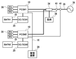
- FIG. 1 is a configuration diagram of a power storage system according to an embodiment of the present invention.
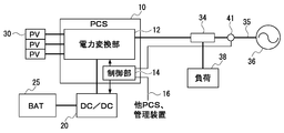
- FIG. 2 is an explanatory diagram of the configuration of each power conditioner included in the power storage system according to the embodiment.
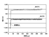
- FIG. 3 is an explanatory diagram of the experimental results.
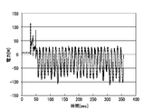
- FIG. 4 is an enlarged view of BATP 2 shown in FIG.
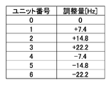
- FIG. 5 is an explanatory diagram of the adjustment amount information.
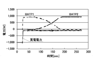
- FIG. 6 is an explanatory diagram of an experiment result on the power storage system according to the embodiment.
- FIG. 1 shows a configuration diagram of a power storage system according to an embodiment of the present invention
- FIG. 2 shows an explanatory diagram of the configuration of each power conditioner 10 included in the power storage system.
- the power storage system includes a plurality (two in the figure) of power conditioners (PCS) connected to a power system 36 and an AC load 38 via a distribution board 34. ) 10 and a management device 28 connected to each power conditioner 10 by a communication line 16.
- PCS power conditioners
- the power conditioner 10 is a hybrid power conversion device that is connected to a solar battery (PV) 30 and connected to a storage battery (BAT) 25 via a bidirectional DC / DC converter (DC / DC) 20. .
- the power conditioner 10 includes a power converter 12 connected to the solar cell 30, the bidirectional DC / DC converter 20, and the distribution board 34, and a controller 14.
- the power conversion unit 12 is a unit in which a plurality of switching elements, a reactor, and the like are combined so that a state exemplified below can be taken.
- a state in which power from the power system 36 is supplied to the AC load 38 and / or the storage battery 25 A state in which power from the storage battery 25 is supplied to the AC load 38 together with or alone from the power system 36
- the control unit 14 is a unit that controls the power conversion unit 12 and the bidirectional DC / DC converter 20.
- the control unit 14 includes a processor (a microcontroller in this embodiment), a gate driver IC, and the like.
- the output of the current sensor 41 attached to the power line 35 connecting the distribution board 34 and the power system 36 is input to the control unit 14.
- the output voltage of the solar cell 30, the voltage on the distribution board 34 side of the power conversion unit 12, and the like are also input to the control unit 14.
- the same number of current sensors 41 as the number of power conditioners 10 are attached to the power line 35, and a plurality of control units 14 (power conditioners 10) in the power storage system are connected to the power line 35. Outputs of different current sensors 41 are input.
- the management device 28 is a kind of computer connected to the control unit 14 in each power conditioner 10 through the communication line 16.
- the management device 28 collects information related to the operation status (the amount of power generated by the solar cell 30 and the like) from each power conditioner 10 and stores the information in the inside, and the function to display the information stored in the inside in various formats. have.
- the power storage system is configured as a system in which each power conditioner 10 is identified by a unit number. When the operation of the power storage system is started (at the time of installation), a unit number (in this embodiment, a serial number starting from “0”) is set for each power conditioner 10 using the management device 28.
- the control unit 14 in the power conditioner 10 is a unit that periodically performs control processing for controlling the power conversion unit 12 and the bidirectional DC / DC converter 20 based on the output of the current sensor 41 and the like.
- controlling the power converter 12 and the bidirectional DC / DC converter 20 performs ON / OFF control (PWM control) of a plurality of switching elements in the power converter 12 and the bidirectional DC / DC converter 20. That's what it means.
- control processes performed by the control unit 14 are a control process for outputting (discharging) a certain amount of power to the storage battery 25 and a control process for inputting (charging) a certain amount of power to the storage battery 25. Is included.
- the control process (hereinafter referred to as a storage battery control process) related to charging / discharging of the storage battery 25 performed by the control unit 14 is almost hunting if the power conditioner 10 is used alone. It is processing that does not.
- the default storage battery control process is a storage battery control process whose execution cycle (hereinafter also referred to as a control cycle) is a basic switching cycle that is a cycle at the time of factory shipment.
- FIGS. 3 and 4 are obtained.
- the experimental results shown in FIG. 3 show that the two power conditioners 10 with the solar cells 30 removed are connected to a simulated system simulating the power system 36, and the target of purchased power (power input from the simulated system) The value is 100 W, the power consumption by the AC load 38 is 1000 W, and each control unit 14 is obtained by performing default storage battery control processing.
- BATP1 is input / output power of one storage battery 25
- BATP2 is input / output power of the other storage battery 25.
- the power output from the storage battery 25 is indicated by plus
- the power input to the storage battery 25 is indicated by minus.
- FIG. 4 is an enlarged view of BATP 2 shown in FIG.
- the inventor has also found that hunting of charge / discharge power of each storage battery can be suppressed by making the control cycle of each control unit vary more largely than variations caused by individual differences of crystal oscillators. Specifically, in order to reduce noise during operation, the control cycle of the control unit is usually about 20 kHz, but the difference between the control cycles of the two control units is about 4 Hz or more. It has been found that the charging / discharging power hunting of each storage battery can be reduced to a practically sufficient level.
- hunting of charge / discharge power can also be suppressed by setting the power storage system to a system that starts operation after setting the control cycle of each control unit 14 so as to satisfy the above conditions.
- hunting of charge / discharge power occurs due to a setting mistake and the storage battery 25 deteriorates, it is better to perform such setting automatically.
- the power conditioner 10 allows the control unit 14 to operate the management device 28 from the adjustment amount information indicating the correspondence between the unit ID and the adjustment amount of the control cycle as illustrated in FIG.
- the adjustment amount corresponding to the unit ID assigned to itself is read out, and the storage battery control process is executed (programmed) in a cycle in which the read out adjustment amount is added.
- the control cycle of the two control units is different, so that hunting of charge / discharge power of each storage battery 25 is reduced to a practically sufficient level. I can do it.
- the adjustment amount in FIG. 5 may be an integer multiple of the minimum resolution of the clock obtained by frequency-dividing the period of the crystal oscillator with the Micoro controller. However, it is assumed that the optimum value of the adjustment amount differs depending on the design of the control unit 14.
- the experimental results shown in FIG. 6 are obtained.
- the experimental results in FIG. 6 show that the two power conditioners 10 with the solar cells 30 removed are connected to a simulated system simulating the power system, the target value of power input from the simulated system is 100 W, and the AC load 38 This is obtained by letting each control unit 14 perform the storage battery control process at the adjusted (changed) control cycle, assuming that the power consumption by 1000 is 1000W.
- BATP1 decreases and BATP2 increases as time elapses The reason why BATP1 decreases and BATP2 increases as time elapses is that the power conditioner 10 does not take into account the charge / discharge power of the storage battery 25 in the other power conditioners 10, This is because the current sensor 41 has individual differences in addition to being configured as a device for determining and controlling electric power. In addition, when the storage battery discharged during the experiment was switched from BATP1 to BATP2, it was confirmed that no hunting phenomenon occurred.
- the adjustment amount information (FIG. 5) described above is information that directly indicates the correspondence between the unit ID and the adjustment amount of the control cycle.
- Information indicating the relationship indirectly may be information indicating the correspondence between the unit ID and the adjusted control cycle directly / indirectly.
- the information indirectly indicating the correspondence between the unit ID and the adjustment amount of the control period includes the change amount of the unit ID and the timer setting value that defines the control period (positive or negative to be added to the timer setting value) Information indicating the relationship with the As information that indirectly indicates the correspondence between the unit ID and the adjusted control cycle, information indicating the relationship between the unit ID and the set value of the timer can be exemplified.
- the adjustment amount information directly or indirectly indicating the correspondence between the unit ID and the adjustment amount of the control cycle or the adjusted control cycle is information embedded as a program code or data in the program. Alternatively, it may be information read by the processor that executed the program.
- the serial number of the other power conditioner 10 is acquired by the control unit 14, and the serial number of the own power conditioner 10 is the serial number in the sorting result of the acquired serial number and the serial number of the own power conditioner 10.
- a function for determining the adjustment amount of the control cycle or the control cycle after adjustment may be provided.
- the management device 18 determines the adjustment amount of the control cycle or the control cycle after the adjustment from the magnitude relationship between the unit ID and the serial number, and the control unit 14 of each power conditioner 10. The system may be modified to notify the system.
- the power storage system according to the embodiment includes a system in which the power conditioner 10 is connected to a power generation device (such as a fuel cell) other than the solar battery 30, a system in which the storage battery 25 is accommodated in the casing of the power conditioner 10,
- the power conversion unit 12 may be modified into a system that also has a function as the bidirectional DC / DC converter 20. Furthermore, the problem that the charging / discharging amount of the storage battery 25 hunts when it is also provided also occurs in the power conditioner 10 that is not connected to the power generation device. Therefore, the power storage system according to the embodiment may be modified to a system including a plurality of power conditioners 10 that perform only charge / discharge control of the storage battery 25.
Abstract
Description
・電力系統36からの電力を交流負荷38及び/又は蓄電池25に供給する状態
・蓄電池25からの電力を電力系統36からの電力と共に又は単独で交流負荷38に供給する状態
・太陽電池30からの電力を、蓄電池25、交流負荷38及び電力系統36の中の1つ以上に供給する状態
上記した実施形態に係る蓄電システムは、各種の変形を行うことが出来るものである。例えば、上記した調整量情報(図5)は、ユニットIDと制御周期の調整量の対応関係を直接的に示す情報であったが、調整量情報は、ユニットIDと制御周期の調整量の対応関係を間接的に示す情報であっても、ユニットIDと調整後の制御周期の対応関係を直接的/間接的に示す情報であっても良い。なお、ユニットIDと制御周期の調整量の対応関係を間接的に示す情報としては、ユニットIDと、制御周期を規定するタイマの設定値の変更量(タイマの設定値に加算すべき正又は負の値)との関係を示す情報を例示できる。ユニットIDと調整後の制御周期の対応関係を間接的に示す情報としては、ユニットIDと、タイマの設定値との関係を示す情報を例示できる。
12 電力変換部
14 制御部
16 通信ライン
20 双方向DC/DCコンバータ
25 蓄電池
28 管理装置
30 太陽電池
34 分電盤
35 電力線
36 電力系統
38 交流負荷
41 電流センサ
Claims (7)
- 電力系統及び交流負荷に接続される、同一の基本スイッチング周期を持つ複数のパワーコンディショナを含む蓄電システムにおいて、
前記複数のパワーコンディショナは、それぞれ、
前記電力系統からの電力を前記交流負荷及び/又は自パワーコンディショナに接続される蓄電池に供給すること、及び、当該蓄電池に充電された電力を前記電力系統からの電力と共に又は単独で前記交流負荷に供給することが可能な電力変換部と、
前記複数のパワーコンディショナと前記電力系統との間を流れる入出力電流の大きさに基づき、前記複数のパワーコンディショナと前記電力系統との間で目標量の電力が授受されるように前記電力変換部を制御する制御処理を周期的に行う制御部であって、前記制御処理の実行周期を前記基本スイッチング周期から変更可能な制御部と、
を備え、
前記複数のパワーコンディショナ内の複数の制御部による前記制御処理の実行周期が互いに異なるように変更されている、
ことを特徴とする蓄電池システム。 - 前記制御部は、自パワーコンディショナの固有情報に対応づけられている周期に前記制御処理の実行周期を変更する機能を有する
ことを特徴とする請求項1に記載の蓄電池システム。 - 前記固有情報が、前記蓄電システムの運用開始時に各パワーコンディショナに割り当てられるユニット番号である
ことを特徴とする請求項2に記載の蓄電池システム。 - 各パワーコンディショナは、前記制御部による前記制御処理の実行周期を変更する設定変更部を、さらに含む
ことを特徴とする請求項1に記載の蓄電池システム。 - 前記パワーコンディショナは、発電装置と接続可能であり、
前記電力変換部は、前記発電装置からの電力を前記蓄電池、前記交流負荷及び前記電力系統の中の1つ以上に供給する機能を有する
ことを特徴とする請求項1から4のいずれか一項に記載の蓄電池システム。 - 前記制御部は、水晶発振子の周期を分周して得られるクロックの最少分解能の整数倍に対応する時間分、前記制御処理の実行周期を前記基本スイッチング周期から変更可能なユニットである
ことを特徴とする請求項1から5のいずれか一項に記載の蓄電池システム。 - 電力系統及び交流負荷に接続される、基本スイッチング周期をもつパワーコンディショナであって、
前記電力系統からの電力を前記交流負荷及び/又は自パワーコンディショナに接続される蓄電池に供給すること、及び、当該蓄電池に充電された電力を前記電力系統からの電力と共に又は単独で前記交流負荷に供給することが可能な電力変換部と、
前記電力系統への電力線を流れる入出力電流の大きさに基づき、前記電力線により目標量の電力が伝送されるように前記電力変換部を制御する制御処理を周期的に行う制御部であって、前記制御処理の実行周期を前記基本スイッチング周期から変更可能な制御部と、
を備えることを特徴とするパワーコンディショナ。
Priority Applications (2)
| Application Number | Priority Date | Filing Date | Title |
|---|---|---|---|
| US15/750,841 US20180248372A1 (en) | 2016-03-11 | 2016-12-06 | Power storage system and power conditioner |
| KR1020187004521A KR20180029251A (ko) | 2016-03-11 | 2016-12-06 | 축전 시스템 및 파워 컨디셔너 |
Applications Claiming Priority (2)
| Application Number | Priority Date | Filing Date | Title |
|---|---|---|---|
| JP2016048371A JP2017163787A (ja) | 2016-03-11 | 2016-03-11 | 蓄電システム及びパワーコンディショナ |
| JP2016-048371 | 2016-03-11 |
Publications (1)
| Publication Number | Publication Date |
|---|---|
| WO2017154295A1 true WO2017154295A1 (ja) | 2017-09-14 |
Family
ID=59789105
Family Applications (1)
| Application Number | Title | Priority Date | Filing Date |
|---|---|---|---|
| PCT/JP2016/086201 WO2017154295A1 (ja) | 2016-03-11 | 2016-12-06 | 蓄電システム及びパワーコンディショナ |
Country Status (4)
| Country | Link |
|---|---|
| US (1) | US20180248372A1 (ja) |
| JP (1) | JP2017163787A (ja) |
| KR (1) | KR20180029251A (ja) |
| WO (1) | WO2017154295A1 (ja) |
Cited By (2)
| Publication number | Priority date | Publication date | Assignee | Title |
|---|---|---|---|---|
| WO2020085424A1 (ja) * | 2018-10-26 | 2020-04-30 | 株式会社九電工 | 再生可能エネルギーを用いた電力供給設備 |
| JP2020072637A (ja) * | 2018-10-26 | 2020-05-07 | 株式会社九電工 | 再生可能エネルギーを用いた電力供給設備 |
Families Citing this family (1)
| Publication number | Priority date | Publication date | Assignee | Title |
|---|---|---|---|---|
| KR102353146B1 (ko) | 2018-03-13 | 2022-01-18 | 주식회사 엘지화학 | 페라이트계 코팅 촉매의 제조방법 및 이를 이용한 부타디엔의 제조방법 |
Citations (3)
| Publication number | Priority date | Publication date | Assignee | Title |
|---|---|---|---|---|
| JP2010233292A (ja) * | 2009-03-26 | 2010-10-14 | Fuji Electric Holdings Co Ltd | 電力変換システムのノイズ低減法 |
| JP2015082954A (ja) * | 2013-10-24 | 2015-04-27 | 富士電機株式会社 | 自立運転システム、自立運転制御装置および蓄電池システム |
| JP2015211480A (ja) * | 2014-04-23 | 2015-11-24 | 株式会社ノーリツ | 発電システムの電圧上昇抑制制御方法 |
Family Cites Families (9)
| Publication number | Priority date | Publication date | Assignee | Title |
|---|---|---|---|---|
| JP2810081B2 (ja) * | 1989-02-08 | 1998-10-15 | 株式会社日立製作所 | Pwm電力変換装置 |
| JP2000092848A (ja) * | 1998-09-16 | 2000-03-31 | Toyo Electric Mfg Co Ltd | 電力変換装置の多数台運転方法 |
| US6529979B1 (en) * | 1999-11-08 | 2003-03-04 | International Business Machines Corporation | Method and apparatus for a high-speed serial communications bus protocol with positive acknowledgement |
| JP3740118B2 (ja) * | 2002-11-19 | 2006-02-01 | 三菱重工業株式会社 | 系統連係システム |
| JP4102278B2 (ja) * | 2003-03-19 | 2008-06-18 | 三菱電機株式会社 | 風力発電システム |
| JP2004312922A (ja) * | 2003-04-09 | 2004-11-04 | Toyota Motor Corp | 電力変換器制御装置 |
| US10468993B2 (en) * | 2007-05-17 | 2019-11-05 | Enphase Energy, Inc. | Inverter for use in photovoltaic module |
| US8345454B1 (en) * | 2009-11-21 | 2013-01-01 | The Boeing Company | Architecture and control method for dynamically conditioning multiple DC sources to driven an AC load |
| JP5612718B2 (ja) * | 2011-05-18 | 2014-10-22 | 国立大学法人 東京大学 | 多端子型非同期連系装置、電力機器制御端末装置と電力ネットワークシステムおよびその制御方法 |
-
2016
- 2016-03-11 JP JP2016048371A patent/JP2017163787A/ja active Pending
- 2016-12-06 KR KR1020187004521A patent/KR20180029251A/ko not_active Application Discontinuation
- 2016-12-06 WO PCT/JP2016/086201 patent/WO2017154295A1/ja active Application Filing
- 2016-12-06 US US15/750,841 patent/US20180248372A1/en not_active Abandoned
Patent Citations (3)
| Publication number | Priority date | Publication date | Assignee | Title |
|---|---|---|---|---|
| JP2010233292A (ja) * | 2009-03-26 | 2010-10-14 | Fuji Electric Holdings Co Ltd | 電力変換システムのノイズ低減法 |
| JP2015082954A (ja) * | 2013-10-24 | 2015-04-27 | 富士電機株式会社 | 自立運転システム、自立運転制御装置および蓄電池システム |
| JP2015211480A (ja) * | 2014-04-23 | 2015-11-24 | 株式会社ノーリツ | 発電システムの電圧上昇抑制制御方法 |
Cited By (3)
| Publication number | Priority date | Publication date | Assignee | Title |
|---|---|---|---|---|
| WO2020085424A1 (ja) * | 2018-10-26 | 2020-04-30 | 株式会社九電工 | 再生可能エネルギーを用いた電力供給設備 |
| JP2020072637A (ja) * | 2018-10-26 | 2020-05-07 | 株式会社九電工 | 再生可能エネルギーを用いた電力供給設備 |
| JP7097869B2 (ja) | 2018-10-26 | 2022-07-08 | 株式会社九電工 | 再生可能エネルギーを用いた電力供給設備 |
Also Published As
| Publication number | Publication date |
|---|---|
| US20180248372A1 (en) | 2018-08-30 |
| KR20180029251A (ko) | 2018-03-20 |
| JP2017163787A (ja) | 2017-09-14 |
Similar Documents
| Publication | Publication Date | Title |
|---|---|---|
| JP5726555B2 (ja) | 太陽光発電システム | |
| JP5925554B2 (ja) | 制御装置、制御システム、及び制御方法 | |
| WO2015122196A1 (ja) | 在宅状況判定装置、配送システム、在宅状況判定方法、在宅状況判定プログラム、および配送端末 | |
| WO2017154295A1 (ja) | 蓄電システム及びパワーコンディショナ | |
| JP2011250673A (ja) | エネルギーコントローラおよび制御方法 | |
| JP5796189B2 (ja) | 電力供給システム | |
| JPWO2016084396A1 (ja) | 電力制御装置、電力制御方法及び電力制御システム | |
| JP5960641B2 (ja) | 充電装置 | |
| JP2012235631A (ja) | 二次電池充電装置、二次電池充電システム及び二次電池充電方法 | |
| US20100320957A1 (en) | Method and device for charging rechargeable batteries | |
| US9876350B2 (en) | Power supply system | |
| JP5947270B2 (ja) | 電力供給システム | |
| JP2008072774A (ja) | 自然エネルギー発電電力平準化装置 | |
| JP2015208129A (ja) | 電力制御システム、電力制御装置、および電力制御方法 | |
| KR102029030B1 (ko) | 장주기 및 단주기 특성을 모두 고려하는 전력저장시스템 운전 제어 장치 및 방법 | |
| JP2017147898A (ja) | 蓄電装置及びマイクロバッテリ | |
| KR101324516B1 (ko) | 전기 제품과 접속되는 전원 공급 제어장치 및 이의 배터리 충전 방법 | |
| JP2012210076A (ja) | 充放電制御回路 | |
| JP2023030289A (ja) | バッテリーユニットの制御装置 | |
| JP6489332B2 (ja) | 蓄電池ユニット及び蓄電システム | |
| JP2013051838A (ja) | 電池運用装置、電池運用方法及びコンピュータプログラム | |
| JP2019193317A (ja) | 蓄電システム、充放電制御装置、その制御方法、およびプログラム | |
| JP2019154108A (ja) | 蓄電システム | |
| JP2013099046A (ja) | 蓄・給電装置 | |
| JP2019154109A (ja) | 蓄電システム |
Legal Events
| Date | Code | Title | Description |
|---|---|---|---|
| WWE | Wipo information: entry into national phase |
Ref document number: 15750841 Country of ref document: US |
|
| ENP | Entry into the national phase |
Ref document number: 20187004521 Country of ref document: KR Kind code of ref document: A |
|
| NENP | Non-entry into the national phase |
Ref country code: DE |
|
| 121 | Ep: the epo has been informed by wipo that ep was designated in this application |
Ref document number: 16893619 Country of ref document: EP Kind code of ref document: A1 |
|
| 122 | Ep: pct application non-entry in european phase |
Ref document number: 16893619 Country of ref document: EP Kind code of ref document: A1 |