WO2017154162A1 - 紙幣分類装置 - Google Patents
紙幣分類装置 Download PDFInfo
- Publication number
- WO2017154162A1 WO2017154162A1 PCT/JP2016/057528 JP2016057528W WO2017154162A1 WO 2017154162 A1 WO2017154162 A1 WO 2017154162A1 JP 2016057528 W JP2016057528 W JP 2016057528W WO 2017154162 A1 WO2017154162 A1 WO 2017154162A1
- Authority
- WO
- WIPO (PCT)
- Prior art keywords
- bill
- bills
- insertion slot
- storage unit
- banknote
- Prior art date
- Legal status (The legal status is an assumption and is not a legal conclusion. Google has not performed a legal analysis and makes no representation as to the accuracy of the status listed.)
- Ceased
Links
Images



Classifications
-
- B—PERFORMING OPERATIONS; TRANSPORTING
- B65—CONVEYING; PACKING; STORING; HANDLING THIN OR FILAMENTARY MATERIAL
- B65H—HANDLING THIN OR FILAMENTARY MATERIAL, e.g. SHEETS, WEBS, CABLES
- B65H1/00—Supports or magazines for piles from which articles are to be separated
- B65H1/02—Supports or magazines for piles from which articles are to be separated adapted to support articles on edge
-
- G—PHYSICS
- G07—CHECKING-DEVICES
- G07D—HANDLING OF COINS OR VALUABLE PAPERS, e.g. TESTING, SORTING BY DENOMINATIONS, COUNTING, DISPENSING, CHANGING OR DEPOSITING
- G07D9/00—Counting coins; Handling of coins not provided for in the other groups of this subclass
-
- G—PHYSICS
- G07—CHECKING-DEVICES
- G07D—HANDLING OF COINS OR VALUABLE PAPERS, e.g. TESTING, SORTING BY DENOMINATIONS, COUNTING, DISPENSING, CHANGING OR DEPOSITING
- G07D9/00—Counting coins; Handling of coins not provided for in the other groups of this subclass
- G07D9/04—Hand- or motor-driven devices for counting coins
Definitions
- the present invention relates to a bill sorting device.
- a bill depositing apparatus installed in a back yard of a head office or branch of a bank or a cash center is well known as an apparatus used for cash inspection of a financial institution.
- confirmation of the number of sheets and authenticity determination, integrity separation treatment for sorting regular banknotes and unfit banknotes, banding processing for bundling the sorted banknotes in a band, and the like are performed.
- a means for stacking the paper sheets in an aligned state is required. For example, as in the case of overseas banknotes, the short and long size of the banknotes become large for each denomination In such a country, it is necessary to match the bill insertion slot and the stacking unit to the largest bill, which makes it difficult to align small bills.
- the stacking port does not have a mechanism for aligning the banknotes, and during stacking, the banknotes are accumulated in the left and right without being uniform.
- the present invention is made in view of the above, and an object of the present invention is to provide a bill sorting device capable of offsetting bills at the time of insertion and at the time of accumulation without reducing the reliability.
- the bill sorting device stores a bill insertion slot, a discriminating unit which discriminates whether or not the bill can be accepted, and a bill discriminated by the discriminating unit.
- the sorting mechanism includes a bill storage portion, and a transport path connecting the bill insertion slot, the determination portion, and the bill storage portion, and the sorting mechanism is configured to face the apparatus installation surface in the bill transport width direction.
- the bill insertion port is installed at a predetermined angle, and the bill insertion port has an insertion port bias roller for offsetting the bill to be inserted on one side which is one end of the direction in which the bill insertion port is inclined, the storage section
- the storage unit is configured as a bill sorting device having a storage unit offset roller for offsetting the stored bills on one side which is one end of the storage direction in the inclined direction.
- bills can be offset at the time of insertion and accumulation without lowering the reliability.
- FIG. 1 It is a general view of a banknote depositing device. It is a block diagram which shows the functional structure of the banknote classification apparatus shown in FIG. It is a side view of the banknote depositing device shown in FIG. It is explanatory drawing of the method of arrange
- a bill sorting device according to the present invention will be described in detail with reference to the attached drawings.
- the following describes the case where the bill sorting device and the bill sorting mechanism according to the present invention are applied to a bill depositing apparatus such as a sorter including a bill bundle winding device, but the present invention is not limited to this. It can be applied to various devices to be integrated.
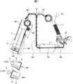
- FIG. 1 is an overall view of the bill depositing apparatus.
- a bill insertion slot 10, a return slot 20, and an operation unit 3 are disposed on the front side of the bill depositing apparatus.
- the operation unit 3 may be disposed on the side surface, or may be configured by an information processing terminal such as a detachable tablet electrically connected to the device.
- a bill discrimination unit 30 and a bill storage unit 40 are provided, and in the bill storage unit 40, delivery of bills is performed between the bill bundle winding device 100 for bundling stacked bills.
- An opening 90 is provided for this purpose.
- a large number of bills are often stacked on a hopper or a stacking opening, considering cooperation with the bill bundle winding apparatus 100
- the bill depositing apparatus described below the piled bills are offset by the offset rollers provided in the bill insertion slot 10 and the bill storage portion 40, and the mechanism including these is inclined in the offset direction. It is possible to align a large amount of banknotes to be handled.
- the classification mechanism having the angle .theta. Is disposed at an appropriate angle .theta.
- the sorting mechanism is installed in the apparatus such that the right side in the bill width direction is higher than the left side in the bill width direction by a predetermined angle.
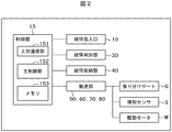
- FIG. 2 is a block diagram showing a functional configuration of the banknote sorting apparatus shown in FIG.
- the banknote classification device functionally includes a control unit 15 including a host communication unit 151, a main control unit 152, and a memory 153.
- the control unit 15 controls the operations of the bill depositing / dispensing port 10, the bill discriminating unit 30, the bill storage unit 40, and the transport paths 50 to 80 connecting these.
- a distribution gate G for sorting out acceptable banknotes and non-acceptable banknotes, and a plurality of transport gates of the transport paths 50 to 80 for detecting the transport of the banknotes provided at predetermined intervals.
- a detection sensor S and a drive motor M for transporting bills on the transport paths 50 to 80 are provided, and operate in response to an instruction from the control unit 15 in the same manner as the transport paths 50 to 80.
- the upper level communication unit 151 is a processing unit that transmits / receives various information for deposit to / from a host computer for managing the banknotes deposited into the banknote depositing device or the banknote depositing device.
- the main control unit 152 reads the discrimination result of the bill by the bill discriminating unit 30, stores it in the memory 153, counts the number of bills stored in the bill storage unit 40, stores it in the memory 153, etc.
- the control unit 151 controls the operation of each unit of the control unit 151 including the unit 151.
- the discrimination result is, for example, the denomination and number of acceptable banknotes, and the denomination and number of unacceptable banknotes.
- the memory 153 stores various information processed by the main control unit 152.
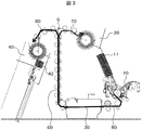
- FIG. 3 is a side view of the bill depositing apparatus shown in FIG.
- a bill insertion slot 10 where the user inserts bills
- a return slot for returning bills unsuitable for depositing. 20 and are arranged.
- the bill discrimination unit 30 and the bill storage unit 40 are respectively disposed on the rear side of the apparatus (left side in FIG. 3) which is the back side, and are connected by conveyance paths 50, 60, 70 and 80.
- the bill discrimination unit 30 can perform denomination discrimination and authenticity discrimination of the bill to be transported from the front, which is the upstream side, to the rear, which is the downstream side. Whether the bill can be accepted or returned It can be judged.
- the bill that has been separated one by one from the bill insertion slot 10 and fed out is conveyed to the bill discriminating portion 30 through the conveyance path 50.
- the bill discrimination unit 30 discriminates the denomination, authenticity, and state of the conveyed bill, and determines whether or not the bill is received while the bill passes through the transport path 60.
- Acceptable bills are distributed by the gate G to the conveyance path connected to the conveyance path 80 and accumulated in the bill storage unit 40.
- the unacceptable banknotes are distributed by the gate G to the transport path connected to the transport path 70 and accumulated in the return port 20.
- each mechanism described above for example, the drive of the rollers of the transport path, the switching of the distribution gate of the transport path, and the like are drive-controlled by the control unit 15 (not shown).
- the control unit 15 (not shown).
- the drive motor M for driving the transport paths
- the transport path 80 for transporting the bills to the bill storage portion 40
- An electromagnetic solenoid for switching the distribution gate G for switching to 70, a detection sensor S (not shown) for detecting the conveyance of the bill, and the like (not shown) are arranged, and a drive motor and an electromagnetic solenoid required according to the bill transaction.
- the state of conveyance of the bill is monitored using the detection signal of the detection sensor.
- FIG. 4 a top view of the inlet is shown in the upper right, a front view of the inlet is shown in the lower right, and a side view of the inlet is shown on the left.
- an actuator such as a conveyance motor and a delivery motor.
- the delivery motor is a motor for delivering the banknotes by the delivery rollers 12 and 13.
- the transport motor is a motor for delivering the banknotes delivered by the delivery rollers 12 and 13.
- the sorting mechanism is inclined at an appropriate angle toward one side (left in this example) of the transport direction, the operator can set a large amount of bills in the bill insertion slot 10. It can be expected that the banknotes are aligned and set at a position approaching in the direction of gravity without being conscious of it.
- the classification mechanism including the bill insertion slot 10 is one side which is one end of the classification mechanism in the longitudinal width direction of the bill from the horizontal plane which is the installation surface of the bill depositing device. (In this example, the right side) is disposed to be inclined so as to be higher by a predetermined angle ⁇ .
- the unit casing of the classification mechanism may be supported from below by a support.
- a plurality of offset rollers 11 having a rotation axis in a direction not perpendicular to the direction in which the inserted bills are reduced (that is, the bill accumulation direction Q).
- the respective offset rollers 11 rotate in the same direction (the direction of the arrow A), The end face of the bill in the longitudinal direction can be rubbed to move the bill to one side (the direction of the arrow B).
- the bills fed to one side by touching the offset roller 11 are separated one by one by the delivery rollers 12 and 13 rotating in the delivery direction of the bills, and the separation roller 14, and are delivered to the transport path 50.
- the offset roller 11 provided in the bill insertion slot 10 rotates in the direction to bias the accumulated bills P toward one end of the bill insertion slot 10 on the low inclination side, the inclination of the sorting mechanism Due to the effect and the rotation effect of the bias roller 11, a large amount of banknotes can be brought close to one side at a time and fed out.
- the offset direction of the stacked bills P and the feeding direction of the bills fed out from the stacked bills P are perpendicular to each other.
- the single-sided bill P 1 is separated and fed by the feed roller 13 and the separation roller 14, and further, the following bill P 2 is fed by the feed roller 12.
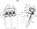
- FIG. 5 the front view of the accumulation port is shown on the left side, and the side view of the accumulation port is shown on the right side.
- the bills conveyed to the bill storage unit 40 are accumulated one by one between the blades of the accumulation wheel 41 moving in synchronization with the conveyance of the bills, and the inside of the bill storage unit 40 follows the rotation of the accumulation wheel 41 (arrow C direction). At that time, it is difficult to align the bills in the left-right direction because of inhibiting factors such as air resistance, static electricity, and friction. Therefore, similarly to the bill insertion slot 10, the bill storage portion 40 also has the offset roller 42 having a rotation axis in a direction not perpendicular to the direction in which the accumulated bills increase (ie, the bill accumulation direction R). , Rotate in the A direction.
- the entire mechanism is inclined by an angle ⁇ to facilitate aligning the bills in the direction of gravity, so that the accuracy of aligning the bills is improved.
- the classification mechanism including the bill storage unit 40 is one end of the classification mechanism in the longitudinal width direction of the bill from the horizontal plane, which is the installation surface of the bill depositing device.
- the right side is arranged to be higher by a predetermined angle ⁇ .
- the bills dropped from the accumulation wheel 41 and accumulated on the accumulation plate 43 are It slips naturally to the low side of the slope along its slope and is offset.
- a method of inclining the classification mechanism as in the case of the bill insertion slot 10, it may be supported from below by a support.
- control unit 15 may start rotating the offset roller 42 at the timing when conveyance of bills starts, or at a timing at which a sensor arranged upstream of the accumulation wheel 41 detects the first bill, rotation. It is also possible to get started.
- the accumulation plate 43 can move downward (in the direction of the arrow D) according to the number of accumulated bills, and can always maintain a space for accumulation.
- various conventionally known techniques such as control by a drive motor and an electromagnetic solenoid can be used.
- stacked banknotes can be aligned on one side by a bias roller having a rotation axis in a direction not orthogonal to the direction in which the banknotes increase. That is, since the bias roller 42 provided in the bill storage unit 40 rotates in a direction to bias the accumulated bills S to one end of the accumulation plate 43 of the bill storage unit 40 on the low inclination side, the sorting mechanism Due to the inclination effect of and the rotation effect of the bias roller 42, a large amount of conveyed banknotes can be moved to one side at any time and accumulated.
- FIG. 6 is a view showing an arrangement relationship between the classification mechanism and the bill depositing device.
- a part of the mechanism shown in FIG. 5 is omitted.
- the sorting mechanism and the bill bundle winding machine are arranged at a predetermined angle ⁇ with respect to the line H parallel to the installation surface of the bill depositing apparatus with respect to the bill depositing apparatus.
- the entire device can be installed on the floor of the store of the financial institution in the same manner as the conventional device.
- the control unit 15 stops the feeding motor that rotates the feeding rollers 12 and 13.
- the conveyance motor, the accumulation motor for operating the accumulation plate 43 of the bill storage unit 40, and the drive motor for the offset roller 42 are stopped, and a series of operations are completed. .
- the control unit 15 operates the accumulation motor to lower the accumulation plate 43 in the downward direction T. , Stop at the position of the opening 90.
- the accumulated bills S accumulated on the accumulation plate 43 lowered to the position of the opening 90 are delivered to the banknote bundle winding device 100 through the opening 90.
- an arm X controlled by a drive mechanism such as a drive motor or an electromagnetic solenoid is provided on the bill storage portion 40 side.
- the bill S may be gripped and pushed out from the collecting plate 43 in the direction Y of the bill bundle winding device 100 and conveyed.
- the bill bundle winding device 100 is provided with an arm X ′ controlled by a drive mechanism such as a drive motor or an electromagnetic solenoid, and the stacked bills S are grasped by the arm X ′ , And may be transported in the direction Y of the banknote bundle winding device 100.
- the method of conveying the stacked bills S may be adopted in consideration of the space of the bill storage unit 40 and the bill bundle winding device 100.
- the opening 90 is provided on the side of the bill storage unit 40, and the bill bundle winding device 100 is provided on the opening 90 side.
- the bill bundle winding device 100 may be provided on the opening 90 side.
- a sensor (not shown) provided in the bill insertion slot 10 detects the bill insertion and a case where the feeding can be started automatically has been described.
- the operation panel or the tablet it is possible to instruct the start of counting by the operation of a staff member.
- the offset roller 42 it is also possible to arrange the offset roller 42 only in the bill storage portion 40 or to arrange the offset roller 11 only in the bill insertion slot 10.
- the return port 20 may be provided with the same offset roller as the offset roller 42.
- the bias roller rotates in the direction to bias the bill to one end of the return port 20 on the lower side of the tilt, so the tilt effect of the sorting mechanism and the bias roller 42 Because of the rotation effect of, it is possible to collect and return the returned bills at any time to one side. Therefore, the operator can easily grasp and return the returned accumulated bills.
- the classification mechanism is arranged to be inclined by a predetermined angle ⁇ , but the angle may be adjustable to an arbitrary angle. For example, depending on the number of banknotes to be deposited, the number of banknotes may be large, medium, or small.
- the angle can be determined according to the size of the contact surface between the offset roller 11 and the stacked banknotes set in the banknote insertion slot 10. Specifically, as shown in FIG. 4, when a bill of a small size that contacts two of the three offset rollers 11 is set, and all of the three offset rollers 11 are contacted. Consider the case of setting a bill of such a large size.
- the bill can be offset in the same manner as in the latter case by providing a further inclination in the former case than the latter.
- the offset roller 11 provided in the bill insertion slot 10 offsets the banknote
- the offset roller 42 provided in the banknote storage unit 40 can be considered similarly. .
Landscapes
- Physics & Mathematics (AREA)
- General Physics & Mathematics (AREA)
- Engineering & Computer Science (AREA)
- Mechanical Engineering (AREA)
- Pile Receivers (AREA)
Abstract
紙幣投入口と、紙幣の受け付け可否を判別する判別部と、判別部により判別された紙幣を収納する紙幣収納部と、紙幣投入口と判別部と紙幣収納部とを接続する搬送路とを備えた分類機構を備え、分類機構は、紙幣搬送幅方向に、装置設置面に対して所定の角度傾斜して設置され、紙幣投入口は、紙幣投入口が傾斜する方向の一端である片側に、投入する紙幣を片寄せする投入口片寄せローラを有し、収納部は、収納部が傾斜する方向の一端である片側に、収納する紙幣を片寄せする収納部片寄せローラを有する。
Description
本発明は、紙幣分類装置に関する。
従来、金融機関の現金精査に用いられる装置として、銀行の本店や支店のバックヤード、あるいは現金センタに設置されている紙幣入金装置がよく知られている。精査の際には、枚数の確認と真偽判定、正券紙幣と損券紙幣とを仕分けする正損分離処置や、区分けされた紙幣を帯で束ねる帯封処理などを行っている。帯封処理などをするには、紙葉類を整列させた状態で集積させる手段が必要となるが、例えば、海外の紙幣のように、紙幣の短手、長手サイズが金種ごとに大きくことなるような国では、いちばん大きい紙幣に、紙幣投入口や集積部を合わせる必要があり、小さい紙幣をそろえることが困難になる。
これまで、このような事例において、効果的な解決手段は無く、紙幣の投入口ならびに、集積口のサイズを制限することで、解決しているが、海外のように、紙幣の大きさにばらつきがある場合には、手段がなく、紙幣のセット時、ならびに集積時に確実に紙幣を端によせる機構が求められる。上記機構として、例えば、特許文献1には、集積部直前の搬送路を紙幣の到着タイミングにあわせ、傾けて、紙幣を片側に寄せて集積する機構が開示されている。
例えば、銀行のバックヤードなどで使用される紙幣入金装置は、大量の紙幣が紙幣投入口部に積まれることが多く、また、束巻き機との連携を考慮すると、投入時だけではなく、紙幣を判別、集積後においても、集積紙幣をそろえる必要がある。
これまでの紙幣入金装置では、異なる大きさの紙幣をそろえようとすると、紙幣大きさに応じて、投入口の紙幣ガイドの位置を変える必要がある。また、集積口において紙幣をそろえる機構を有しておらず、集積時には、紙幣が左右にそろわず集積されてしまう。
特許文献1の紙幣取引装置では、集積部直前の搬送路を紙幣の到着タイミングにあわせ、傾けて、紙幣を片側に寄せて集積する機構が開示されているが、大量の紙幣を高速に取り扱うような紙幣入金機では、一枚一枚の紙幣について、搬送ガイドを傾斜させる動作をする必要があり、機構の信頼性、寿命に問題がある。すなわち、従来の装置では、紙幣を片寄せするために、搬送路自体を傾斜させるための傾斜機構が必要となる。このため、大量の紙幣を高速に処理する場合、搬送路の傾斜動作を繰り返すことにより、傾斜機構の耐久性が損なわれてしまう。その結果、傾斜機構のみならず装置自体の寿命が短くなり、装置の信頼性が低下してしまう。
本発明は、上記に鑑みてなされたものであって、信頼性を低下させることなく、投入時および集積時に紙幣を片寄せすることが可能な紙幣分類装置を提供することを目的とする。
上記課題を解決し、目的を達成するために、本発明にかかる紙幣分類装置は、紙幣投入口と、前記紙幣の受け付け可否を判別する判別部と、前記判別部により判別された紙幣を収納する紙幣収納部と、前記紙幣投入口と前記判別部と前記紙幣収納部とを接続する搬送路とを備えた分類機構を備え、前記分類機構は、紙幣搬送幅方向に、装置設置面に対して所定の角度傾斜して設置され、前記紙幣投入口は、前記紙幣投入口が前記傾斜する方向の一端である片側に、投入する紙幣を片寄せする投入口片寄せローラを有し、前記収納部は、前記収納部が前記傾斜する方向の一端である片側に、収納する紙幣を片寄せする収納部片寄せローラを有する、ことを特徴とする紙幣分類装置として構成される。
本発明によれば、信頼性を低下させることなく、投入時および集積時に紙幣を片寄せすることができる。
以下、添付図面を参照して、本発明にかかる紙幣分類装置の実施形態について詳細に説明する。以下では、本発明にかかる紙幣分類装置、紙幣分類機構を、紙幣束巻き装置を含むソータ等の紙幣入金装置に適用した場合について説明しているが、これに限らず、大量の紙幣を投入して集積する様々な装置に適用することができる。
図1は、紙幣入金装置の全体図である。図1に示すように、紙幣入金装置の前面側には、紙幣投入口10と、返却口20と、操作部3とが配置されている。操作部3は、側面に配置されていてもよいし、装置と電気的に接続された着脱可能なタブレット等の情報処理端末により構成されていてもよい。また、紙幣入金装置の背面側には、紙幣判別部30と、紙幣収納部40とが設けられ、紙幣収納部40には、集積紙幣を束ねる紙幣束巻き装置100との間で紙幣の受け渡しをするための開口部90が設けられている。紙幣束巻き装置を含むソータ等の紙幣入金装置では、ATM(Automated Teller Machine)とは異なり、大量の紙幣をホッパや集積口に積まれること多く、紙幣束巻き装置100との連携を考慮して紙幣を整列させる需要が大きい。そのため、以下に示す紙幣入金装置では、紙幣投入口10や紙幣収納部40に設けられた片寄せローラにより集積紙幣を片寄せするとともに、これらを含む機構自体を片寄せ方向に傾斜させることにより、取り扱う大量の紙幣を整列させることを可能としている。
紙幣投入口10、紙幣判別部30、紙幣収納部40を含み、紙幣投入口10から紙幣判別部30を経由して紙幣収納部40または返却口20まで紙幣を搬送するための搬送路50~80を有した分類機構は、地面に対し、適切な角度θ度斜めに配置されている。上記分類機構を、紙幣分類装置の設置面である地面に対して斜めに配置することにより、大量の紙幣を重力方向に揃えやすくなり、顧客も、意識することなく、紙幣を端によせて、セットすることができる、本例では、紙幣幅方向の右側が紙幣幅方向の左側よりも所定の角度だけ高くなるように、上記分類機構が装置内に設置されている。
図2は、図1に示した紙幣分類装置の機能的な構成を示すブロック図である。図2に示すように、紙幣分類装置は、機能的には、上位通信部151と、主制御部152と、メモリ153とを含む制御部15を有している。制御部15は、上記紙幣入出金口10、紙幣判別部30、紙幣収納部40、これらを接続する搬送路50~80の動作を制御する。なお、搬送路50~80には、受付可能な紙幣とそうでない紙幣とを振り分けるための振り分けゲートGと、搬送路50~80に所定間隔で設けられた紙幣の搬送を検知するための複数の検知センサSと、搬送路50~80上の紙幣を搬送するための駆動モータMとが設けられ、搬送路50~80と同様に、制御部15からの指示を受けて動作する。
上記上位通信部151は、紙幣入金装置や紙幣入金装置に入金された紙幣を管理するためのホストコンピュータとの間で入金のための各種情報を送受信する処理部である。主制御部152は、紙幣判別部30による紙幣の判別結果を読み取り、メモリ153に記憶させたり、紙幣収納部40に収納された紙幣の枚数をカウントし、メモリ153に記憶させる等、上位通信部151を含む制御部151を構成する各部の動作を制御する。上記判別結果とは、例えば、受付可能な紙幣の金種や枚数、受付不可能な紙幣の金種や枚数である。メモリ153は、主制御部152が処理した様々な情報を記憶する。
図3は、図1に示した紙幣入金装置の側面図である。図3に示すように、紙幣入金装置において、その装置前面側(図3右側)には、利用者が紙幣の投入を行う紙幣投入口10と、入金に不適な紙幣を返却するための返却口20とが配置されている。紙幣判別部30と紙幣収納部40とが、その奥側である装置背面側(図3左側)にそれぞれ配置され、搬送路50、60、70および80で接続されている。
上記のように、紙幣判別部30は、上流側である前方から下流側である後方へ搬送する紙幣の金種判別および、真偽判別を行うことができ、紙幣を受付可能か返却するかを判断することができる。紙幣投入口10より1枚ずつ分離され、繰り出された紙幣は、搬送路50をとおり、紙幣判別部30へ搬送される。紙幣判別部30は、搬送された紙幣の金種、真偽、状態を判別し、当該紙幣が搬送路60を通る間に、紙幣を受け付けるか否かを判定する。受付可能な紙幣は、ゲートGにより、搬送路80につながる搬送路に振り分けられ、紙幣収納部40へ集積される。受付不可な紙幣は、ゲートGにより搬送路70につながる搬送路に振り分けられ、返却口20へ集積される。
上記の各機構部の駆動、例えば、搬送路のローラの駆動、搬送路の振り分けゲートの切り替え等は、上記制御部15(図示省略)により駆動制御される。なお、搬送路50~80を含む上記各機構部には、これらの搬送路を駆動する駆動モータM、紙幣収納部40に紙幣を搬送する搬送路80と返却口20に紙幣を搬送する搬送路70とを切替えるための振り分けゲートGを切替える電磁ソレノイド、及び紙幣の搬送を検知する検知センサSなど(図示せず)が配置されており、紙幣の取引に応じて必要な駆動モータや電磁ソレノイドが駆動され、また検知センサの検知信号を用いて紙幣の搬送状態が監視される。以上のように構成された紙幣入金装置により、紙幣の計数/収納処理を実行することができる。
次に、紙幣をそろえる方法について、図4を参照して説明する。図4では、右上段に投入口の上面図を示し、右下段に投入口の正面図を示し、その左に投入口の側面図を示している。係員が、紙幣を紙幣投入口10に装填すると、紙幣投入口10に設置されている1つ以上のセンサが、紙幣の投入を検知し、搬送モータ、繰り出しモータなどのアクチュエータを駆動させる。上記繰り出しモータは、繰出しローラ12、13による紙幣の繰出しを行うためのモータであり、上記搬送モータは、繰出しローラ12、13により繰り出された紙幣の搬送を行うためのモータである。
上記したように、分類機構が、搬送方向の片側(本例では左)に向かって適切な角度、斜めに傾いているので、大量の紙幣を紙幣投入口10にセットする際に、操作者は意識することなく重力方向に寄せる位置に紙幣を整列させてセットすることが期待できる。具体的には、図4右下段に示すように、紙幣投入口10を含む上記分類機構は、紙幣入金装置の設置面である水平面から、紙幣の長手幅方向における上記分類機構の一端である片側(本例では右側)が、所定の角度θだけ高くなるように傾斜して配置されている。このように、紙幣投入口10の幅方向の一端が紙幣入金装置の設置面から所定の角度だけ傾斜して配置されているので、操作者は、集積紙幣Pのように大量の紙幣を投入しようとする場合であっても、特に意識することなく自然に傾斜の低い側に紙幣を揃えることができる。なお、上記分類機構を傾斜させる方法としては、例えば、上記分類機構のユニット筐体を、支柱によって下側から支えるようにすればよい。
また、紙幣投入口10には、投入された紙幣が減っていく方向と直交しない方向(すなわち、紙幣の集積方向Q)に回転軸を有する複数の片寄せローラ11が配置されている。紙幣投入口10に設けた不図示のセンサが、紙幣を投入するために集積紙幣Pがセットされたことを検知すると、それぞれの片寄せローラ11は、同一方向(矢印A方向)に回転し、紙幣の長手方向の端面をこすり、紙幣を片側(矢印B方向)に寄せることができる。片寄せローラ11に触れ、片側に寄せられた紙幣は、紙幣の繰り出し方向に回転する繰り出しローラ12、13、および分離ローラ14により一枚ずつ分離され、搬送路50に繰り出される。このように、紙幣投入口10に設けられた片寄せローラ11が、上記傾斜の低い側となる紙幣投入口10の一端に集積紙幣Pを片寄せする方向に回転するので、上記分類機構の傾き効果と片寄せローラ11の回転効果とにより、大量の紙幣を一度に片側に寄せて、繰り出すことができる。なお、図中、集積紙幣Pの片寄せ方向と、集積紙幣Pから繰出される紙幣の繰出し方向とは、互いに垂直方向である。図4左では、片寄せされた紙幣P1が、繰り出しローラ13および分離ローラ14により分離されて繰り出され、さらに、続く紙幣P2が繰り出しローラ12によって繰り出されていることがわかる。
続いて、紙幣収納部40において、紙幣をそろえる方法について、図5を参照して説明する。図5では、左側に集積口の正面図を示し、右側に集積口の側面図を示している。
紙幣収納部40まで搬送された紙幣は、紙幣の搬送と同期して動く集積ホイール41の羽根の間に1枚ずつ集積し、集積ホイール41の回転(矢印C方向)に従い、紙幣収納部40内に集積されるが、その際、空気抵抗、静電気、摩擦などの阻害要因のため、紙幣を左右方向にそろえることは困難となる。そのため、紙幣投入口10と同様、紙幣収納部40にも、集積された紙幣が増えていく方向と直交しない方向(すなわち、紙幣の集積方向R)に回転軸を有する片寄せローラ42を配置し、A方向に回転させる。集積する紙幣が集積ホイール41から離れて、集積プレート43に集積する際に、集積した紙幣を片側(矢印B方向)に寄せられる。図5右では、紙幣P3は集積ホイール41を離れて集積プレート43に落下し、紙幣P4およびP5は、集積ホイール41に挟持されていることがわかる。
また、紙幣投入口10と同様に、図5左に示すように、機構全体が角度θ分だけ傾け、重力方向に紙幣を揃える易い構造になっているので、紙幣を揃える精度が向上する。具体的には、図5左に示すように、紙幣収納部40を含む上記分類機構は、紙幣入金装置の設置面である水平面から、紙幣の長手幅方向における上記分類機構の一端である片側(本例では右側)が、所定の角度θだけ高くなるように傾斜して配置されている。このように、紙幣収納部40の幅方向の一端が紙幣入金装置の設置面から所定の角度だけ傾斜して配置されているので、集積ホイール41から落下し、集積プレート43に集積した紙幣は、その傾斜に沿って自然に傾斜の低い側にすべり、片寄せされる。なお、上記分類機構を傾斜させる方法としては、紙幣投入口10と同様、支柱によって下側から支えるようにすればよい。
なお、制御部15は、片寄せローラ42を、紙幣の搬送が始まるタイミングで回転を始めてもよいし、集積ホイール41の手前の上流側に配置するセンサが最初の紙幣を検知したタイミングで、回転を始めることも可能である。
また、集積プレート43は、紙幣の集積枚数に応じ下方向(矢印D方向)に動き、常に、集積するためのスペースを保つことができる。集積プレート43を動かす機構については、駆動モータや電磁ソレノイドによる制御等、従来から知られている様々な技術を用いることができる。
このようにして、集積紙幣を紙幣が増えていく方向と直交しない方向に回転軸を有する片寄せローラで、片側に整列させることができる。すなわち、紙幣収納部40に設けられた片寄せローラ42が、上記傾斜の低い側となる紙幣収納部40の集積プレート43の一端に集積紙幣Sを片寄せする方向に回転するので、上記分類機構の傾き効果と片寄せローラ42の回転効果とにより、搬送されてくる大量の紙幣を随時片側に寄せて、集積することができる。
図6は、上記分類機構と、紙幣入金装置との配置関係を示す図である。図6では、図5に示した一部の機構を省略して示している。既述のとおり、紙幣入金装置に対して、紙幣入金装置の設置面と平行な線Hに対して上記分類機構と紙幣束巻き機が所定の角度θ分だけ傾斜して配置されているが、装置全体としては、従来装置と同じように金融機関の店舗内の床面に設置することができる。
紙幣投入口10に設置している不図示のセンサが、紙幣が無くなったことを検知すると、制御部15は、繰り出しローラ12、13を回転させる繰出しモータを停止させる。繰出された最後の紙幣が紙幣収納部40に集積されると、搬送モータ、紙幣収納部40の集積プレート43を動作させる集積モータ、片寄ローラ42の駆動モータを停止させ、一連の動作が終了する。
さらに、図7に示すように、紙幣収納部40では、すべての紙幣が集積プレート43に集積されると、制御部15は、上記集積モータを動作させ、集積プレート43を下方向Tに下降させ、開口部90の位置で停止させる。開口部90の位置まで下降した集積プレート43に集積された集積紙幣Sは、開口部90を介して紙幣束巻き装置100に受け渡される。集積紙幣Sの受け渡し方法としては、例えば、図7下に示すように、紙幣収納部40側に、駆動モータや電磁ソレノイド等の駆動機構による制御されるアームXを設け、そのアームXにより、集積紙幣Sを掴んで集積プレート43から紙幣束巻き装置100の方向Yに押し出して搬送すればよい。あるいは、これとは逆に、紙幣束巻き装置100側に、駆動モータや電磁ソレノイド等の駆動機構による制御されるアームX’を設け、そのアームX’により、集積紙幣Sを掴んで集積プレート43から紙幣束巻き装置100の方向Yに引き込んで搬送すればよい。いずれの方法により集積紙幣Sを搬送するかは、紙幣収納部40や紙幣束巻き装置100のスペースを考慮して採用すればよい。また、本例では、紙幣収納部40の側面側に開口部90が設けられ、紙幣束巻き装置100がその開口部90側に設けられているが、紙幣収納部40の背面側に開口部90を設け、その開口部90側に紙幣束巻き装置100を設けてもよい。これらの配置についても、上記同様、紙幣入金装置内のスペースを考慮して定めることができる。すなわち、集積紙幣Sが紙幣束巻き装置100に受け渡し可能なように、紙幣束巻き装置100側に開口部90が設けられていればよい。
上記例では、紙幣投入口10に紙幣が置かれると、紙幣投入口10に設けられた不図示のセンサが、紙幣投入を検知して、自動的に繰り出しがスタートすることができる場合について説明したが、操作パネルやタブレットを用いることで、係員の操作により、計数の開始を指示することもできる。また、別の実施例として、紙幣収納部40のみに片寄せローラ42を配置することや、紙幣投入口10のみに片寄せローラ11を配置することも可能である。さらに、返却口20に片寄せローラ42と同様の片寄せローラを設けてもよい。この場合、紙幣収納部40と同様、片寄せローラが、上記傾斜の低い側となる返却口20の一端に紙幣を片寄せする方向に回転するので、上記分類機構の傾き効果と片寄せローラ42の回転効果とにより、返却されてくる紙幣を随時片側に寄せて、集積することができる。したがって、操作者は、返却された集積紙幣を容易に掴んで取り出すことができる。
さらに、本実施例では、上記分類機構を所定の角度θだけ傾けて配置しているが、その角度を任意の角度に調整可能としてもよい。例えば、入金する紙幣枚数に応じて、紙幣枚数が多い場合、中程度の場合、少ない場合の3段階としてもよい。上記角度は、片寄せローラ11と紙幣投入口10にセットされた集積紙幣との接触面の大きさに応じて定めることができる。具体的には、図4に示したように、3つの片寄せローラ11のうちの2つに接触するような小さいサイズの紙幣をセットした場合と、3つの片寄せローラ11のすべてに接触するような大きいサイズの紙幣をセットした場合とを考える。前者の場合、後者の場合に比べて片寄せローラ11から受ける力が小さいため、後者よりも前者の場合に一層傾斜をつけることにより、後者の場合と同様に紙幣を片寄せすることができる。上記例では、紙幣投入口10に設けられた片寄せローラ11が紙幣を片寄せする場合について記載しているが、紙幣収納部40に設けられた片寄せローラ42についても同様に考えることができる。
以上のように、上記した実施例によれば、ユーザが無意識に紙幣を投入口にセットしても、異なったサイズの紙幣でも、紙幣を片側に整列させて集積させる紙幣区分機を実現することができる。すなわち、顧客の操作性を確保しながら、投入時および集積時において紙幣の片寄せ性能を高め、かつ、異なったサイズの紙幣でも、大量の紙幣を自動的に整列させて繰出し、集積させることができる。
1:紙幣取扱装置、
3:操作パネル
10:紙幣投入口
15:制御部
20:返却口
30:紙幣判別部
40:紙幣収納部
50、60、70、80:搬送路
90:開口部
100:紙幣巻取り装置
11、42:片寄せローラ
12、13、14:繰り出しローラ
41:集積ホイール
G:振り分けゲート
S:検知センサ
M:駆動モータ
θ:傾き角。
3:操作パネル
10:紙幣投入口
15:制御部
20:返却口
30:紙幣判別部
40:紙幣収納部
50、60、70、80:搬送路
90:開口部
100:紙幣巻取り装置
11、42:片寄せローラ
12、13、14:繰り出しローラ
41:集積ホイール
G:振り分けゲート
S:検知センサ
M:駆動モータ
θ:傾き角。
Claims (5)
- 紙幣投入口と、前記紙幣の受け付け可否を判別する判別部と、前記判別部により判別された紙幣を収納する紙幣収納部と、前記紙幣投入口と前記判別部と前記紙幣収納部とを接続する搬送路とを備えた分類機構を備え、
前記分類機構は、紙幣搬送幅方向に、装置設置面に対して所定の角度傾斜して設置され、
前記紙幣投入口は、前記紙幣投入口が前記傾斜する方向の一端である片側に、投入する紙幣を片寄せする投入口片寄せローラを有し、
前記収納部は、前記収納部が前記傾斜する方向の一端である片側に、収納する紙幣を片寄せする収納部片寄せローラを有する、
ことを特徴とする紙幣分類装置。 - 前記紙幣分類装置は、前記装置設置面と水平に設置された、前記紙幣収納部に収納された集積紙幣を束ねる紙幣束巻き機を備え、
前記紙幣収納部には、前記紙幣束巻き機との間で前記集積紙幣を受け渡すための開口部が前記紙幣束巻き機側に設けられ、前記紙幣収納部または前記紙幣束巻き機のいずれかに設けられた駆動機構により動作されるアームが前記集積紙幣を受け渡しする、
ことを特徴とする請求項1に記載の紙幣分類装置。 - 前記分類機構は、前記紙幣投入口の集積紙幣と前記投入口片寄せローラとの接触面の大きさ、または前記紙幣収納部の集積紙幣と前記収納部片寄せローラとの接触面の大きさに基づいて、前記所定の角度が定められる、
ことを特徴とする請求項1に記載の紙幣分類装置。 - 前記分類機構は、前記判別部による判別の結果受け付けられない紙幣を返却する返却口を備え、
前記返却口は、前記返却口が前記傾斜する方向の一端である片側に、返却する紙幣を片寄せする返却口片寄せローラを有する、
ことを特徴とする請求項1に記載の紙幣分類装置。 - 前記分類機構は、前記紙幣投入口に設けられたセンサが、前記紙幣投入口に投入する紙幣を検知し、前記紙幣投入口に設けられた繰出しローラにより前記紙幣の繰出しを開始する、
ことを特徴とする請求項1に記載の紙幣分類装置。
Priority Applications (1)
| Application Number | Priority Date | Filing Date | Title |
|---|---|---|---|
| PCT/JP2016/057528 WO2017154162A1 (ja) | 2016-03-10 | 2016-03-10 | 紙幣分類装置 |
Applications Claiming Priority (1)
| Application Number | Priority Date | Filing Date | Title |
|---|---|---|---|
| PCT/JP2016/057528 WO2017154162A1 (ja) | 2016-03-10 | 2016-03-10 | 紙幣分類装置 |
Publications (1)
| Publication Number | Publication Date |
|---|---|
| WO2017154162A1 true WO2017154162A1 (ja) | 2017-09-14 |
Family
ID=59789225
Family Applications (1)
| Application Number | Title | Priority Date | Filing Date |
|---|---|---|---|
| PCT/JP2016/057528 Ceased WO2017154162A1 (ja) | 2016-03-10 | 2016-03-10 | 紙幣分類装置 |
Country Status (1)
| Country | Link |
|---|---|
| WO (1) | WO2017154162A1 (ja) |
Citations (4)
| Publication number | Priority date | Publication date | Assignee | Title |
|---|---|---|---|---|
| JPH0656280A (ja) * | 1992-08-05 | 1994-03-01 | Hitachi Electron Eng Co Ltd | Ocr装置の紙送り方式 |
| JP2009163721A (ja) * | 2007-12-12 | 2009-07-23 | Hitachi Omron Terminal Solutions Corp | 紙幣取扱装置 |
| JP2015203903A (ja) * | 2014-04-11 | 2015-11-16 | グローリー株式会社 | 紙葉類処理装置 |
| JP2015232797A (ja) * | 2014-06-10 | 2015-12-24 | グローリー株式会社 | 束紙幣処理装置および精査処理方法 |
-
2016
- 2016-03-10 WO PCT/JP2016/057528 patent/WO2017154162A1/ja not_active Ceased
Patent Citations (4)
| Publication number | Priority date | Publication date | Assignee | Title |
|---|---|---|---|---|
| JPH0656280A (ja) * | 1992-08-05 | 1994-03-01 | Hitachi Electron Eng Co Ltd | Ocr装置の紙送り方式 |
| JP2009163721A (ja) * | 2007-12-12 | 2009-07-23 | Hitachi Omron Terminal Solutions Corp | 紙幣取扱装置 |
| JP2015203903A (ja) * | 2014-04-11 | 2015-11-16 | グローリー株式会社 | 紙葉類処理装置 |
| JP2015232797A (ja) * | 2014-06-10 | 2015-12-24 | グローリー株式会社 | 束紙幣処理装置および精査処理方法 |
Similar Documents
| Publication | Publication Date | Title |
|---|---|---|
| JP5060019B2 (ja) | ヘッダーカードの処理システム | |
| CN102689704B (zh) | 累积和捆绑设备 | |
| CN101685558B (zh) | 纸张类传送装置 | |
| JP5664355B2 (ja) | 紙葉類処理装置及び取引装置 | |
| US20110314773A1 (en) | Banknote bundling device and banknote bundling method | |
| KR20150047795A (ko) | 횡방향 입출금 방식이 적용된 환류형 지폐/수표 입출금장치 및 그에 적용되는 지폐/수표 처리방법 | |
| US8961275B2 (en) | Coin depositing and dispensing machine | |
| JP2000048234A (ja) | 紙葉類収納機構 | |
| CN102930639A (zh) | 一种纸页类堆叠装置 | |
| WO2015141162A1 (ja) | 紙葉類処理装置 | |
| JP3766466B2 (ja) | 紙葉類の枚数確定方法及び紙葉類取扱装置 | |
| JP5898041B2 (ja) | 搬送ユニット付き紙葉類取扱装置 | |
| CN103003850B (zh) | 纸张类排出装置、纸张类处理装置 | |
| JP2011141612A (ja) | 紙葉類取扱装置 | |
| WO2017154162A1 (ja) | 紙幣分類装置 | |
| JP5321118B2 (ja) | 紙幣処理装置 | |
| JP6230940B2 (ja) | 紙葉類処理装置 | |
| KR101437207B1 (ko) | 매체 수납 조출 장치 | |
| JPH1186092A (ja) | 紙葉類搬送装置および自動取引装置 | |
| JP5176739B2 (ja) | 紙幣処理装置及び金銭処理機 | |
| WO2014002117A1 (en) | System and method for currency collection and presentation | |
| JP6750466B2 (ja) | 紙幣処理装置 | |
| JP7774584B2 (ja) | 紙葉類取扱装置及び異物検出方法 | |
| KR101709093B1 (ko) | 수표 및 지폐 입출금장치 | |
| JP4608814B2 (ja) | 媒体処理装置 |
Legal Events
| Date | Code | Title | Description |
|---|---|---|---|
| NENP | Non-entry into the national phase |
Ref country code: DE |
|
| 121 | Ep: the epo has been informed by wipo that ep was designated in this application |
Ref document number: 16893492 Country of ref document: EP Kind code of ref document: A1 |
|
| 122 | Ep: pct application non-entry in european phase |
Ref document number: 16893492 Country of ref document: EP Kind code of ref document: A1 |
|
| NENP | Non-entry into the national phase |
Ref country code: JP |