WO2017154138A1 - 水素漏えい防止システム、水素漏えい防止方法水素製造システム、電力貯蔵システム - Google Patents
水素漏えい防止システム、水素漏えい防止方法水素製造システム、電力貯蔵システム Download PDFInfo
- Publication number
- WO2017154138A1 WO2017154138A1 PCT/JP2016/057393 JP2016057393W WO2017154138A1 WO 2017154138 A1 WO2017154138 A1 WO 2017154138A1 JP 2016057393 W JP2016057393 W JP 2016057393W WO 2017154138 A1 WO2017154138 A1 WO 2017154138A1
- Authority
- WO
- WIPO (PCT)
- Prior art keywords
- hydrogen
- furnace
- water vapor
- electrolysis unit
- electrolysis
- Prior art date
- Legal status (The legal status is an assumption and is not a legal conclusion. Google has not performed a legal analysis and makes no representation as to the accuracy of the status listed.)
- Ceased
Links
Images


Classifications
-
- C—CHEMISTRY; METALLURGY
- C25—ELECTROLYTIC OR ELECTROPHORETIC PROCESSES; APPARATUS THEREFOR
- C25B—ELECTROLYTIC OR ELECTROPHORETIC PROCESSES FOR THE PRODUCTION OF COMPOUNDS OR NON-METALS; APPARATUS THEREFOR
- C25B1/00—Electrolytic production of inorganic compounds or non-metals
- C25B1/01—Products
- C25B1/02—Hydrogen or oxygen
- C25B1/04—Hydrogen or oxygen by electrolysis of water
-
- C—CHEMISTRY; METALLURGY
- C25—ELECTROLYTIC OR ELECTROPHORETIC PROCESSES; APPARATUS THEREFOR
- C25B—ELECTROLYTIC OR ELECTROPHORETIC PROCESSES FOR THE PRODUCTION OF COMPOUNDS OR NON-METALS; APPARATUS THEREFOR
- C25B15/00—Operating or servicing cells
-
- G—PHYSICS
- G01—MEASURING; TESTING
- G01M—TESTING STATIC OR DYNAMIC BALANCE OF MACHINES OR STRUCTURES; TESTING OF STRUCTURES OR APPARATUS, NOT OTHERWISE PROVIDED FOR
- G01M3/00—Investigating fluid-tightness of structures
- G01M3/02—Investigating fluid-tightness of structures by using fluid or vacuum
- G01M3/04—Investigating fluid-tightness of structures by using fluid or vacuum by detecting the presence of fluid at the leakage point
- G01M3/16—Investigating fluid-tightness of structures by using fluid or vacuum by detecting the presence of fluid at the leakage point using electric detection means
-
- G—PHYSICS
- G01—MEASURING; TESTING
- G01N—INVESTIGATING OR ANALYSING MATERIALS BY DETERMINING THEIR CHEMICAL OR PHYSICAL PROPERTIES
- G01N25/00—Investigating or analyzing materials by the use of thermal means
- G01N25/20—Investigating or analyzing materials by the use of thermal means by investigating the development of heat, i.e. calorimetry, e.g. by measuring specific heat, by measuring thermal conductivity
- G01N25/22—Investigating or analyzing materials by the use of thermal means by investigating the development of heat, i.e. calorimetry, e.g. by measuring specific heat, by measuring thermal conductivity on combustion or catalytic oxidation, e.g. of components of gas mixtures
-
- G—PHYSICS
- G01—MEASURING; TESTING
- G01N—INVESTIGATING OR ANALYSING MATERIALS BY DETERMINING THEIR CHEMICAL OR PHYSICAL PROPERTIES
- G01N27/00—Investigating or analysing materials by the use of electric, electrochemical, or magnetic means
- G01N27/02—Investigating or analysing materials by the use of electric, electrochemical, or magnetic means by investigating impedance
- G01N27/04—Investigating or analysing materials by the use of electric, electrochemical, or magnetic means by investigating impedance by investigating resistance
-
- Y—GENERAL TAGGING OF NEW TECHNOLOGICAL DEVELOPMENTS; GENERAL TAGGING OF CROSS-SECTIONAL TECHNOLOGIES SPANNING OVER SEVERAL SECTIONS OF THE IPC; TECHNICAL SUBJECTS COVERED BY FORMER USPC CROSS-REFERENCE ART COLLECTIONS [XRACs] AND DIGESTS
- Y02—TECHNOLOGIES OR APPLICATIONS FOR MITIGATION OR ADAPTATION AGAINST CLIMATE CHANGE
- Y02E—REDUCTION OF GREENHOUSE GAS [GHG] EMISSIONS, RELATED TO ENERGY GENERATION, TRANSMISSION OR DISTRIBUTION
- Y02E60/00—Enabling technologies; Technologies with a potential or indirect contribution to GHG emissions mitigation
- Y02E60/30—Hydrogen technology
- Y02E60/36—Hydrogen production from non-carbon containing sources, e.g. by water electrolysis
Definitions
- the present invention relates to a hydrogen leakage prevention system, a hydrogen leakage prevention method, a hydrogen production system, and a power storage system.
- steam electrolysis is performed using a solid oxide electrochemical cell group called a stack or a module, in which a plurality of cells are bundled and integrated.
- the hydrogen production method by high-temperature steam electrolysis is a method for producing hydrogen by electrolyzing water vapor at a high temperature (mainly in a temperature range of 500 to 1000 ° C.) using a solid oxide electrochemical cell.
- this solid oxide electrochemical cell is mainly disadvantageous in terms of strength as compared with metal materials and the like because it mainly comprises a solid oxide (ceramics). For this reason, it is required to prevent hydrogen and oxygen from diffusing into the surrounding environment from the solid oxide electrochemical cell or cell stack.
- the problem to be solved by the present invention is to provide a hydrogen leakage prevention system, a hydrogen leakage prevention method, a hydrogen production system, and an electric power storage system that improve safety by stopping the system immediately when hydrogen leaks. That is.
- a hydrogen leakage prevention system includes: An electrolysis unit that electrolyzes water vapor to produce hydrogen and oxygen; An electric furnace that houses the electrolysis section in a furnace and heats the electrolysis section housed; A supply pipe for supplying water vapor to the electrolysis unit; An outflow pipe for flowing out hydrogen from the electrolysis section; A detection device for detecting a gas component in the furnace of the electric furnace; A determination device for determining the presence or absence of hydrogen leakage in the furnace from the data acquired from the detection device; And a control device that controls the amount of water vapor supplied to the electrolysis unit based on the determination by the determination device.
- the conceptual diagram which shows the storage container by the 1st form of this invention The conceptual diagram which shows a solid oxide form electrolysis cell.
- the conceptual diagram which shows the storage container by the 2nd form of this invention The conceptual diagram which shows the storage container by the 3rd form of this invention.
- the conceptual diagram which shows the storage container by the 4th form of this invention The conceptual diagram which shows the storage container by the 5th form of this invention.
- the conceptual diagram which shows the storage container by the 7th form of this invention The conceptual diagram which shows the hydrogen production system and electric power storage system by embodiment of this invention.
- FIG. 1 shows an outline of a preferred specific example of a hydrogen leakage prevention system according to an embodiment of the present invention.
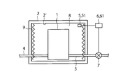
- the hydrogen leakage prevention system shown in FIG. An electrolysis unit 1 for electrolyzing water vapor to produce hydrogen and oxygen; An electric furnace 2 that houses the electrolysis unit 1 in the furnace and heats the electrolysis unit 1 housed therein; A supply pipe 3 for supplying water vapor to the electrolysis unit 1; An outflow pipe 4 through which hydrogen flows out from the electrolysis unit 1; A detection device 5 for detecting a gas component in the furnace of the electric furnace 2, and A determination device 6 for determining the presence or absence of hydrogen leakage in the furnace from the data acquired from the detection device 5; And a control device 7 for controlling the amount of water vapor supplied to the electrolysis unit based on the determination by the determination device 6.
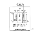
- the electrolysis unit 1 uses a solid oxide having ionic conductivity as an electrolyte, and a plurality of electrolysis cells formed by sandwiching the solid oxide electrolyte between a hydrogen electrode and an oxygen electrode. As shown in FIG. 2, one electrolytic cell 10 is configured by sandwiching an electrolyte 10a made of a solid oxide between a hydrogen electrode 10b and an oxygen electrode 10c, and water (H 2 O) is placed on the hydrogen electrode 10b side.
- the electrolysis unit 1 can be formed by overlapping a plurality of the electrolysis cells 10 (single cells).
- a separator (not shown) can be further arranged between individual cells as necessary.
- the electric furnace 2 accommodates the electrolysis unit 1 in the furnace, and a heater 9 is mainly disposed for heating the electrolysis unit 1 accommodated therein.
- the electric furnace 2 is preferably formed of a heat insulating material.
- One electric furnace 2 can accommodate one or a plurality of solid oxide electrolytic cell stacks 10.
- the electrolysis unit 1 includes a supply pipe 3 for supplying water vapor, an outflow pipe 4 for flowing out hydrogen generated in the electrolysis unit 1, and an oxygen outflow pipe for flowing out oxygen generated in the electrolysis unit 1 in some cases (see FIG. (Not shown) is connected.
- the electrolysis unit 1 is connected to a power supply line (not shown) for supplying power for electrolyzing water vapor.
- a gas other than water vapor can be supplied to the electrolysis unit 1 together with water vapor as necessary.
- the gas other than water vapor include nitrogen and air.
- Hydrogen leaking into the gap 8 is detected by a hydrogen detection device 51 installed in the electric furnace 2, and the determination device 61 determines whether or not hydrogen leaks in the furnace from the data acquired from the detection device 51. Based on this, the controller 7 can control the amount of water vapor supplied to the electrolysis unit 1. For example, the hydrogen concentration in the electric furnace 2 is continuously or intermittently measured by the detection device 51, and the determination device 61 determines the presence of hydrogen in the gap 8 based on the measurement data of the detection device 51. When the presence of a small amount of hydrogen is determined (or when the presence of hydrogen of a predetermined concentration or more is determined), the supply of water vapor to the electrolysis unit 1 can be shut off by closing the control valve of the control device 7. Thereby, electrolysis of water vapor in the electrolysis unit 1 is stopped, generation of hydrogen is stopped, leakage of hydrogen into the electric furnace 2 is stopped, and an increase in hydrogen concentration can be suppressed.
- FIG. 3 shows an outline of a preferable specific example of the hydrogen leakage prevention system according to the embodiment of the present invention.
- the hydrogen leakage prevention system shown in FIG. 3 uses a “water vapor detection device 52” instead of the hydrogen detection device 51 shown in FIG. Therefore, except for the water vapor detection device 52, the same one as described above can be used for the first embodiment.
- water vapor present in the furnace of the electric furnace 2 (that is, the gap 8) is detected by the water vapor detection device 52, and the data acquired from the detection device 52 is used in the electric furnace 2.
- the presence or absence of hydrogen leakage is determined by the determination device 62, and based on the determination, the amount of water vapor supplied to the electrolysis unit 1 is controlled by the control device 7.
- the water vapor detector 52 detects the leaked hydrogen, oxygen that is also present in the gap 8 (for example, oxygen in the air that is present in the gap 8), and the like. It is possible to detect water vapor which is a reaction product.
- the determination device 62 can determine the presence or absence of hydrogen leakage by comparing the data acquired from the water vapor detection device 52 with, for example, water vapor data stored in advance when there is no hydrogen leakage.
- the control valve of the control device 7 can be closed to shut off the supply of water vapor to the electrolysis unit 1. Thereby, electrolysis of water vapor in the electrolysis unit 1 is stopped, generation of hydrogen is stopped, leakage of hydrogen into the electric furnace 2 is stopped, and an increase in hydrogen concentration can be suppressed.
- FIG. 4 shows an outline of a preferable specific example of the hydrogen leakage prevention system according to the embodiment of the present invention.
- the hydrogen leakage prevention system shown in FIG. 4 is configured in such a manner that the detection device 51 is disposed in the flow path 11 of the gas component led from the inside of the electric furnace 2 (specifically, the gap 8). This is the same as the first embodiment shown in FIG.
- the structure 11 can have one end on the electric furnace 2 side opened to the gap 8 and the other end opened to the external space of the electric furnace 2.
- the flow path 11 may have an elongated tubular shape in which one end on the electric furnace 2 side is opened to the gap 8.
- the installation position of the gas component flow path 11 and the acquisition position of the gas from the electric furnace 2 are not particularly limited.
- the gas can be obtained from the inside of the electric furnace 3 through the opening 12 provided above the electric furnace 2 and provided in the ceiling of the electric furnace 2.
- the opening 12 can be provided with a gas flow rate adjusting mechanism 13 or the like as necessary.
- a gas flow rate adjusting mechanism 13 for example, when it is not necessary to detect the hydrogen concentration in the flow path 11, the gas flow is blocked by the gas flow rate adjusting mechanism 13, thereby preventing gas from leaking from the other opening of the flow path 11 to the outside. Can do.
- the gas flow rate is lowered by the gas flow rate adjusting mechanism 13, the temperature drop in the electric furnace 2 accompanying the discharge of the high temperature gas can be suppressed.
- a gas-permeable woven fabric, knitted fabric, cotton-like material, or the like can be preferably used.
- the determination device 61 determines whether or not hydrogen leaks in the furnace from the data installed in the flow path 11 and acquired from the water vapor detection device 51, and based on the determination, the control device 7 supplies water vapor to the electrolysis unit 1. The amount can be controlled.
- the electrolysis of water vapor in the electrolysis unit 1 is stopped, the generation of hydrogen is stopped, the leakage of hydrogen into the electric furnace 2 is stopped, and the increase in the hydrogen concentration is suppressed. be able to.
- the control device 7 controls the amount of water vapor supplied to the electrolysis unit 1. be able to.
- FIG. 5 shows an outline of a preferable specific example of the hydrogen leakage prevention system according to the embodiment of the present invention.
- the hydrogen leakage prevention system of the fourth form shown in FIG. 5 is the same as the third form shown in FIG. 4 except that the combustion catalyst 14 is installed. Therefore, except for the combustion catalyst 14, the third embodiment is the same as described above.
- the combustion catalyst 14 is not particularly limited in material and shape as long as it has an action of oxidizing hydrogen (here, oxidation includes combustion).
- oxidation includes combustion
- the material those containing noble metal components such as Pt and Ru are desirable.
- the shape may be particulate, cylindrical or honeycomb, but is not particularly limited.
- the combustion catalyst 14 is installed on the downstream side of the hydrogen detection device 51 in the flow path of the gas component led from the furnace of the electric furnace 2 to the flow path 11. That is, the gas component guided from the gap 8 of the electric furnace 2 to the flow path 11 passes through the combustion catalyst 14 after the hydrogen concentration is measured by the hydrogen detector 51, and is then discharged from the flow path 11 to the outside. It has become so.
- the determination device 61 determines whether or not hydrogen leaks in the furnace from the data installed in the flow path 11 and acquired from the hydrogen detection device 51, and on the basis of the determination device 61, The amount of water vapor supplied to the electrolysis unit 1 can be controlled.
- the electrolysis of water vapor in the electrolysis unit 1 is stopped, the generation of hydrogen is stopped, the leakage of hydrogen into the electric furnace 2 is stopped, and the increase in the hydrogen concentration is suppressed. be able to.
- FIG. 6 shows an outline of a preferable specific example of the hydrogen leakage prevention system according to the embodiment of the present invention.
- the detection device 5 includes the combustion catalyst 14 and a device 15 for measuring the temperature of the combustion catalyst 14, and the determination device 63.
- the presence or absence of hydrogen leakage in the electric furnace 2 is determined.
- the amount of steam supplied can be controlled.
- the combustion catalyst 14 is not particularly limited in material and shape as long as it has an action of oxidizing hydrogen (here, oxidation includes combustion).
- oxidation includes combustion
- the material those containing noble metal components such as Pt and Ru are desirable.
- the shape may be particulate, cylindrical or honeycomb, but is not particularly limited.
- the determination device 63 determines whether or not hydrogen leaks in the electric furnace 2 from the data acquired from the device 15, and based on the determination, the control device 7 controls the amount of water vapor supplied to the electrolysis unit 1. it can.
- FIG. 7 shows an outline of a preferable specific example of the hydrogen leakage prevention system according to the embodiment of the present invention.
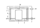
- the detection device 5 has a device 16 for measuring a temperature change in the electric furnace 2
- the determination device 64 has the above-mentioned Determining whether or not hydrogen leaks in the electric furnace 2 from the temperature data acquired from the device 16 for measuring the temperature change, and based on that, the control device 7 controls the amount of steam supplied to the electrolysis unit 1 It is something that can be done.
- the “device 16 for measuring the temperature change in the electric furnace 2 provided there” is provided.
- the presence of hydrogen leaked in the electric furnace 2 and the change (for example, increase) in the amount of hydrogen present can be determined based on the temperature data acquired from “
- an electric resistor can be preferably used. This is to detect a temperature change from a change in resistance value by utilizing the fact that the resistance value of the electric resistor changes due to the temperature change.
- the determination device 64 determines the presence or absence of hydrogen leakage in the electric furnace 2 from the data acquired from the device 16, and the control unit 7 controls the amount of water vapor supplied to the electrolysis unit 1 based on the determination. it can.
- FIG. 8 shows an outline of a preferable specific example of the hydrogen leakage prevention system according to the embodiment of the present invention.
- the detection device 5 is a heater 9 disposed in the furnace of the electric furnace 2, and the control device is connected to the heater 9.
- the presence or absence of hydrogen leakage in the electric furnace 2 is determined from the obtained change in the electric resistance value of the heater 9, and based on this, the amount of water vapor supplied to the electrolysis unit 1 is controlled.
- the heater 9 can be connected to a heater control device 17 that controls the output of the heater 9.
- a heater control device 17 that controls the output of the heater 9.
- the control device 7 can control the amount of water vapor supplied to the electrolysis unit 1. .
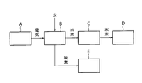
- FIG. 9 is a conceptual diagram of the hydrogen production system and the power storage system.
- the hydrogen production system uses a power generation unit (or electrical energy supply source) A and electric power generated by the power generation unit A to generate hydrogen by decomposing water into hydrogen and oxygen to produce hydrogen.
- a decomposition part B a decomposition part B.
- the power storage system includes a power generation unit (or electrical energy supply source) A, an electrolysis unit B that uses the power from the power generation unit A to decompose water into hydrogen and oxygen to produce hydrogen, and an electrolysis unit B.
- the storage part C which stores the hydrogen manufactured in (1), and the power generation part D which generates electric power using the stored hydrogen as a fuel are provided.
- generated in the electrolysis part B can be stored in the storage part E as needed, and this oxygen can also be utilized as a fluid-like combustion support substance.
- the hydrogen production system is a hydrogen production system for producing hydrogen by supplying water vapor and electric energy to the electrolysis unit B, and electrolyzing the water vapor in the electrolysis unit B, and includes a hydrogen leakage prevention system. It is done.
- the power storage system includes an electrolysis unit B that produces hydrogen by electrolysis of water vapor, a storage unit C that stores hydrogen, and a power generation unit D that generates power using the stored hydrogen as fuel.
- a system comprising a hydrogen leakage prevention system.
- the hydrogen leakage prevention system includes those described in the first to seventh embodiments, and these hydrogen leakage prevention systems are also shown in FIGS. 1 to 8. Further, it can be adapted to the periphery of the electrolysis part B.
- Electrolysis section 2: Electric furnace, 3: Supply pipe, 4: Outflow pipe, 5: Detection device, 6: Determination device, 7: Control device, 8: Air gap, 9: Heater, 10: Solid oxide electrolyte cell 11: flow path, 12: opening, 13: gas flow rate adjusting mechanism, 14: combustion catalyst, 15: device for measuring temperature of combustion catalyst, 16: device for measuring temperature change, 17: heater control device, A: power generation unit, B: electrolysis unit, C: hydrogen storage unit, D: power generation unit, E: oxygen storage unit
Landscapes
- Chemical & Material Sciences (AREA)
- Chemical Kinetics & Catalysis (AREA)
- General Physics & Mathematics (AREA)
- Engineering & Computer Science (AREA)
- Electrochemistry (AREA)
- Physics & Mathematics (AREA)
- Health & Medical Sciences (AREA)
- Organic Chemistry (AREA)
- Biochemistry (AREA)
- General Health & Medical Sciences (AREA)
- Life Sciences & Earth Sciences (AREA)
- Immunology (AREA)
- Pathology (AREA)
- Analytical Chemistry (AREA)
- Materials Engineering (AREA)
- Metallurgy (AREA)
- Combustion & Propulsion (AREA)
- Inorganic Chemistry (AREA)
- Electrolytic Production Of Non-Metals, Compounds, Apparatuses Therefor (AREA)
- Investigating Or Analyzing Materials By The Use Of Electric Means (AREA)
- Examining Or Testing Airtightness (AREA)
Abstract
水素が漏洩した場合、早急にシステムを停止することで安全性を向上させた水素漏えい防止システム、水素漏えい防止方法、水素製造システム、電力貯蔵システムを提供する。水蒸気を電気分解して水素及び酸素を生成させる電解部と、前記電解部を炉内に収容し、この収容された前記電解部の加熱を行う電気炉と、前記電解部に水蒸気を供給する供給管と、前記電解部から水素を取り出す流出管と、前記電気炉の炉内のガス成分を検知する検知装置と、前記検知装置から取得されたデータから前記炉内における水素の漏えいの有無を判定する判定装置と、前記判定装置による判定に基づき、前記電解部に供給される水蒸気量を制御する制御装置とを具備する水素漏えい防止システム。
Description
本発明は、水素漏えい防止システム、水素漏えい防止方法、水素製造システム、電力貯蔵システムに関する。
近年、化石燃料の枯渇、および大気中への二酸化炭素の放出による地球温暖化などの環境問題、エネルギーセキュリティー、などの観点から、太陽光や風力、地熱などに代表される再生可能エネルギーの導入が推進されている。また、二次エネルギーとして、貯蔵や輸送の観点から、水素エネルギーが注目されている。現在、水素の製造方法は、コストや技術の面から、化石燃料を改質する手法が主流となっている。
また、再生可能エネルギーは、近年導入が拡大しているが、その特質上、出力の安定化や電力需要等に対応するように発電量を任意に調整することが難しいという課題がある。
そこで、再生可能エネルギーから取得した電気エネルギーにより水の電気分解(電解)による水素製造を行い、この水素を一旦貯蔵し、必要なときにこの貯蔵された水素を燃料として発電を行う手法が検討されている。
電解による水素製造方法の中で、高効率な手法として、固体酸化物形電気化学セルを用いた高温水蒸気電解がある。なお、通常、水蒸気電解は、スタックあるいはモジュールなどと称されている、複数のセルを束ね統合化した固体酸化物形電気化学セル群を用いて実施されている。
高温水蒸気電解による水素製造方法は、固体酸化物形電気化学セルを用い、高温(主に500~1000℃の温度域)で水蒸気を電気分解し、水素を製造する方法である。一般に、この固体酸化物形電気化学セルは、固体酸化物(セラミックス)を主構成としていることから、金属材などと比較して強度的に不利であることが多い。このことから、固体酸化物電気化学セルやセルスタックから水素や酸素が周囲環境に拡散しないようにすることが求められる。
本発明が解決しようとする課題は、水素が漏洩した場合、早急にシステムを停止することで安全性を向上させた水素漏えい防止システム、水素漏えい防止方法、水素製造システム、電力貯蔵システムを提供することである。
本発明の実施形態による水素漏えい防止システムは、
水蒸気を電気分解して水素および酸素を生成させる電解部と、
前記電解部を炉内に収容し、この収容された前記電解部の加熱を行う電気炉と、
前記電解部に水蒸気を供給する供給管と、
前記電解部から水素を流出させる流出管と、
前記電気炉の炉内のガス成分を検知する検知装置と、
前記検知装置から取得されたデータから前記炉内における水素の漏えいの有無を判定する判定装置と、
前記判定装置による判定に基づき、前記電解部に供給される水蒸気量を制御する制御装置と
を具備するものである。
水蒸気を電気分解して水素および酸素を生成させる電解部と、
前記電解部を炉内に収容し、この収容された前記電解部の加熱を行う電気炉と、
前記電解部に水蒸気を供給する供給管と、
前記電解部から水素を流出させる流出管と、
前記電気炉の炉内のガス成分を検知する検知装置と、
前記検知装置から取得されたデータから前記炉内における水素の漏えいの有無を判定する判定装置と、
前記判定装置による判定に基づき、前記電解部に供給される水蒸気量を制御する制御装置と
を具備するものである。
本発明の実施形態によれば、水素が漏洩した場合、早急にシステムを停止することで安全性を向上させることができる。
<水素漏えい防止システム>
<< 第一の形態 >>
図1は、本発明の実施形態による水素漏えい防止システムの好ましい一具体例の概要について示すものである。
図1に示される水素漏えい防止システムは、
水蒸気を電気分解して水素および酸素を生成させる電解部1と、
電解部1を炉内に収容し、この収容された電解部1の加熱を行う電気炉2と、
電解部1に水蒸気を供給する供給管3と、
電解部1から水素を流出させる流出管4と、
電気炉2の炉内のガス成分を検知する検知装置5と、
検知装置5から取得されたデータから炉内における水素の漏えいの有無を判定する判定装置6と、
判定装置6による判定に基づき、電解部に供給される水蒸気量を制御する制御装置7と
を具備するものである。
<< 第一の形態 >>
図1は、本発明の実施形態による水素漏えい防止システムの好ましい一具体例の概要について示すものである。
図1に示される水素漏えい防止システムは、
水蒸気を電気分解して水素および酸素を生成させる電解部1と、
電解部1を炉内に収容し、この収容された電解部1の加熱を行う電気炉2と、
電解部1に水蒸気を供給する供給管3と、
電解部1から水素を流出させる流出管4と、
電気炉2の炉内のガス成分を検知する検知装置5と、
検知装置5から取得されたデータから炉内における水素の漏えいの有無を判定する判定装置6と、
判定装置6による判定に基づき、電解部に供給される水蒸気量を制御する制御装置7と
を具備するものである。
電解部1は、電解質としてイオン伝導性を持つ固体酸化物を用い、この固体酸化物電解質を水素極と酸素極とで挟んで構成されてなる電解セルが、複数重ね合わされてなるものである。図2に示されるように、一つの電解セル10は、固体酸化物からなる電解質10aを水素極10bと酸素極10cとで挟んで構成されてなり、この水素極10b側に水(H2O)が水蒸気の形態で供給され、水素極10bにおける H2O+2e- → H2+O2- の反応によって水素の生成がなされ、一方、酸素極10cにおける O2- → 1/2 O2+2e- の反応によって酸素の生成がなされる結果、電解セル10に供給された水が、水素と酸素へと電気分解されるようになっている。
この電解セル10(単セル)が複数個重ね合わせて、電解部1を形成することができる。なお、個々のセルとセルとの間には、必要に応じてさらにセパレータ(図示せず)を配置することができる。
電気炉2は、前記電解部1を炉内に収容し、主として、この収容された電解部1の加熱を行うためにヒータ9が配置されている。この電気炉2は、断熱性材料で形成されていることが好ましい。一つの電気炉2は、固体酸化物形電解セルスタック10を1個または複数個収容することができる。
電解部1には、水蒸気を供給する供給管3と、電解部1で生成された水素を流出させる流出管4と、場合により、電解部1で生成された酸素を流出させる酸素流出管(図示せず)が接続されている。また、この電解部1には、水蒸気の電気分解を行うための電力を供給するための電力供給線(図示せず)が接続される。
電解部1からの漏えい物(例えば、水素、酸素あるいは水蒸気)がある場合、これらは、電気炉2の内部(即ち、電気炉2の炉の内面2’とこの電気炉2に収容された電解部1との間の空隙8)に漏出することになる。ここで、電解部1には、必要に応じて、水蒸気と共に水蒸気以外のガスを供給することができる。水蒸気以外のガスとしては、例えば窒素、空気を挙げることができる。
空隙8に漏出した水素は、電気炉2内に設置された水素検知装置51によって検知され、検知装置51から取得されたデータから前記炉内における水素の漏えいの有無を判定装置61にて判定し、それに基づき、制御装置7において、電解部1に供給される水蒸気量を制御することができる。例えば、検知装置51で電気炉2内の水素濃度を継続的ないし断続的に計測し、この検知装置51の計測データをもとに、空隙8における水素の存在を判定装置61が判定し、極微量の水素の存在を判定した場合(もしくは所定濃度以上の水素の存在を判定した場合)に、制御装置7の制御弁を閉じて、電解部1への水蒸気の供給を遮断することができる。これによって、電解部1での水蒸気の電気分解が停止され、水素の生成が停止され、電気炉2内への水素の漏えいが停止され、水素濃度の上昇を抑えることができる。
以上の本発明の第一の形態による水素漏えい防止システムによれば、水素が電解部から漏洩した場合、早急にシステムを停止することで安全性を向上させることができる。かつ、水素製造効率の低下した状態での運転を避けることができる。
<< 第二の形態 >>
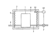
図3は、本発明の実施形態による水素漏えい防止システムの好ましい一具体例の概要について示すものである。
図3に示される水素漏えい防止システムは、図1に記載された水素検知装置51の代わりに「水蒸気検知装置52」を用いるものである。したがって、水蒸気検知装置52以外は、第一の形態に関して、前記したものと同様なものを用いることができる。
図3は、本発明の実施形態による水素漏えい防止システムの好ましい一具体例の概要について示すものである。
図3に示される水素漏えい防止システムは、図1に記載された水素検知装置51の代わりに「水蒸気検知装置52」を用いるものである。したがって、水蒸気検知装置52以外は、第一の形態に関して、前記したものと同様なものを用いることができる。
本発明の第二の形態は、電気炉2の炉内(即ち、空隙8)に存在する水蒸気を、水蒸気検知装置52で検知し、この検知装置52から取得されたデータから電気炉2内における水素の漏えいの有無を判定装置62で判定し、それに基づき、電解部1に供給される水蒸気量を制御装置7で制御するものである。
この水蒸気検知装置52は、電解部1から空隙8へ水素の漏出が生じた場合、その漏出した水素と、同じく空隙8に存在する酸素(例えば、空隙8に存在する空気中の酸素)等との反応生成物である水蒸気を検知することができるようになっている。
判定装置62では、水蒸気検知装置52から取得されたデータと、例えば予め蓄積された水素漏えいがない場合の水蒸気データとを対比することによって、水素漏えいの有無を判定することできる。
判定装置62が水素の漏えいを判定した場合、制御装置7の制御弁を閉じて、電解部1への水蒸気の供給を遮断することができる。これによって、電解部1での水蒸気の電気分解が停止され、水素の生成が停止され、電気炉2内への水素の漏えいが停止され、水素濃度の上昇を抑えることができる。
以上の本発明の第二の形態による水素漏えい防止システムによれば、水素が電解部から漏えいした場合、早急にシステムを停止することで安全性を向上させることができる。かつ、水素製造効率の低下した状態での運転を避けることができる。
<< 第三の形態 >>
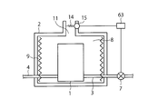
図4は、本発明の実施形態による水素漏えい防止システムの好ましい一具体例の概要について示すものである。
図4に示される水素漏えい防止システムは、検知装置51が、電気炉2の炉内(具体的には、空隙8)から導かれたガス成分の流路11中に配置されている以外は、図1に示される第一の形態と同様のものである。
図4は、本発明の実施形態による水素漏えい防止システムの好ましい一具体例の概要について示すものである。
図4に示される水素漏えい防止システムは、検知装置51が、電気炉2の炉内(具体的には、空隙8)から導かれたガス成分の流路11中に配置されている以外は、図1に示される第一の形態と同様のものである。
したがって、ガス成分の流路11が設けられ、電気炉2の炉内から導かれたガス成分を検知できるように水素検知装置51が設置されている以外は、第一の形態に関して、前記したものと同様なものである。
ガス成分の流路11は、そこに水素検知装置51が設置可能であって、そこに電気炉2の炉内の空隙8に存在するガスを流通しえるようなっているならば、その構造、形態等は特に制限されない。例えば、図4のように、流路11は、電気炉2側の一端が空隙8に開口し、もう一端が電気炉2の外部空間に開口していることができる。また、流路11は、電気炉2側の一端が空隙8に開口した細長い管状形態をしていてもよい。
ガス成分の流路11の設置位置ならびに電気炉2からのガスの取得位置も特に制限されない。好ましくは、図4のように、電気炉2の上方に設置し、電気炉2の天井部に設けられた開口部12を通して電気炉3内部からガスを取得することができる。
なお、この開口部12には、必要に応じて、ガス流量の調整機構13等を設けることができる。例えば、流路11において水素濃度の検知が必要でない時には、このガス流量の調整機構13でガス流を遮断することによって、流路11の他方の開口から外部へガスが漏出することを防止することができる。このガス流量の調整機構13でガス流量を低下させる場合は、高温ガスの排出に伴う、電気炉2内の温度低下を抑制することができる。この場合のガス流量の調整機構13としては、好ましくは、ガス透過性の織物、編み物、綿状物等を挙げることができる。
流路11に設置され水蒸気検知装置51から取得されたデータから前記炉内における水素の漏えいの有無を判定装置61にて判定し、それに基づき、制御装置7において、電解部1に供給される水蒸気量を制御することができる。
これによって、第一の形態と同様に、電解部1での水蒸気の電気分解が停止され、水素の生成が停止され、電気炉2内への水素の漏えいが停止され、水素濃度の上昇を抑えることができる。
以上の本発明の第三の形態による水素漏えい防止システムによれば、水素が電解部から漏えいした場合、早急にシステムを停止することで安全性を向上させることができる。かつ、水素製造効率の低下した状態での運転を避けることができる。
また、水素検知装置51の代わりに水蒸気検知装置52を用いることによっても、同様に水素の漏えいの有無を判定でき、それに基づき、制御装置7において、電解部1に供給される水蒸気量を制御することができる。
<< 第四の形態 >>
図5は、本発明の実施形態による水素漏えい防止システムの好ましい一具体例の概要について示すものである。
図5に示される第四の形態の水素漏えい防止システムは、燃焼触媒14が設置されていること以外は、図4に示される第三の形態と同様なものである。したがって、燃焼触媒14以外は、第三の形態に関して、前記したものと同様なものである。
図5は、本発明の実施形態による水素漏えい防止システムの好ましい一具体例の概要について示すものである。
図5に示される第四の形態の水素漏えい防止システムは、燃焼触媒14が設置されていること以外は、図4に示される第三の形態と同様なものである。したがって、燃焼触媒14以外は、第三の形態に関して、前記したものと同様なものである。
燃焼触媒14は、水素を酸化(ここでの酸化とは、燃焼を包含する)させる作用を有するものであるならば、材質や形状などは特に問わない。材質に関しては、PtやRuなどの貴金属成分を含むものが望ましい。形状についても、粒子状、円筒状、ハニカム状等が挙げられるが、特に問わない。
この第四の形態においては、電気炉2の炉内から流路11に導かれたガス成分の流路中の水素検知装置51の下流側に、燃焼触媒14が設置されている。即ち、電気炉2の空隙8から流路11に導かれたガス成分は、水素検知装置51によって水素濃度が測定された後、燃焼触媒14を透過し、その後、流路11から外部へ排出されるようになっている。
このように燃焼触媒14が設置されていることによって、電解部2から空隙8へ水素が漏えいしたとしても、漏えいした水素が流路11から外部へ排出されることが防止されている。
第三の態様と同様に、流路11に設置され水素検知装置51から取得されたデータから前記炉内における水素の漏えいの有無を判定装置61にて判定し、それに基づき、制御装置7において、電解部1に供給される水蒸気量を制御することができる。
これによって、第三の形態と同様に、電解部1での水蒸気の電気分解が停止され、水素の生成が停止され、電気炉2内への水素の漏えいが停止され、水素濃度の上昇を抑えることができる。
以上の本発明の第四の形態による水素漏えい防止システムによれば、水素が電解部から漏洩した場合、早急にシステムを停止することで安全性を向上させることができる。かつ、水素製造効率の低下した状態での運転を避けることができる。さらに、電気炉から周囲環境への水素の漏えいが防止されているので、さらなる安全性の向上が達成されている。
<< 第五の形態 >>
図6は、本発明の実施形態による水素漏えい防止システムの好ましい一具体例の概要について示すものである。
図6に示される第五の形態の水素漏えい防止システムは、具体的には、検知装置5が、燃焼触媒14およびこの燃焼触媒14の温度を計測する装置15を有し、かつ、判定装置63が、前記燃焼触媒14の温度を計測する装置15から取得された温度データをもとに、電気炉2内における水素の漏えいの有無を判定し、それに基づき、制御装置7において、電解部1に供給される水蒸気量を制御することができるものである。
図6は、本発明の実施形態による水素漏えい防止システムの好ましい一具体例の概要について示すものである。
図6に示される第五の形態の水素漏えい防止システムは、具体的には、検知装置5が、燃焼触媒14およびこの燃焼触媒14の温度を計測する装置15を有し、かつ、判定装置63が、前記燃焼触媒14の温度を計測する装置15から取得された温度データをもとに、電気炉2内における水素の漏えいの有無を判定し、それに基づき、制御装置7において、電解部1に供給される水蒸気量を制御することができるものである。
燃焼触媒14は、水素を酸化(ここでの酸化とは、燃焼を包含する)させる作用を有するものであるならば、材質や形状などは特に問わない。材質に関しては、PtやRuなどの貴金属成分を含むものが望ましい。形状についても、粒子状、円筒状、ハニカム状等が挙げられるが、特に問わない。
燃焼触媒14は、そこでの水素と酸素との反応を受けてその温度が上昇することから、そこに設けられた「燃焼触媒14の温度を計測する装置(温度センサ)15」から取得された温度データをもとに、酸化触媒14における水素(即ち、電気炉2内で漏出した水素)の存在ならびに水素存在量の変化(例えば増大)を検知することができる。
前記装置15から取得されたデータから電気炉2内における水素の漏えいの有無を判定装置63にて判定し、それに基づき、制御装置7において、電解部1に供給される水蒸気量を制御することができる。
以上の本発明の第五の形態による水素漏えい防止システムによれば、水素が電解部から漏洩した場合、早急にシステムを停止することで安全性を向上させることができる。かつ、水素製造効率の低下した状態での運転を避けることができる。さらに、電気炉から周囲環境への水素の漏えいが防止されているので、さらなる安全性の向上が達成されている。
<< 第六の形態 >>
図7は、本発明の実施形態による水素漏えい防止システムの好ましい一具体例の概要について示すものである。
図7に示される第六の形態の水素漏えい防止システムは、具体的には、検知装置5が、電気炉2内の温度変化を計測する装置16を有し、かつ、判定装置64が、前記温度変化を計測する装置16から取得された温度データから前記電気炉2内における水素の漏えいの有無を判定し、それに基づき、制御装置7が前記電解部1に供給される蒸気量を制御することができるものである。
図7は、本発明の実施形態による水素漏えい防止システムの好ましい一具体例の概要について示すものである。
図7に示される第六の形態の水素漏えい防止システムは、具体的には、検知装置5が、電気炉2内の温度変化を計測する装置16を有し、かつ、判定装置64が、前記温度変化を計測する装置16から取得された温度データから前記電気炉2内における水素の漏えいの有無を判定し、それに基づき、制御装置7が前記電解部1に供給される蒸気量を制御することができるものである。
電気炉2内の温度は、水素の漏えいが生じた場合、水素と酸素との反応を受けて温度が上昇することから、そこに設けられた「電気炉2内の温度変化を計測する装置16」から取得された温度データをもとに、電気炉2内で漏出した水素の存在ならびに水素存在量の変化(例えば増大)を判定することができる。
温度変化を計測する装置16としては、好ましくは電気抵抗器を用いることができる。これは、電気抵抗器の抵抗値が温度変化によって変化することを利用して、抵抗値の変化から温度変化を検出するものである。
前記装置16から取得されたデータから電気炉2内における水素の漏えいの有無を判定装置64にて判定し、それに基づき、制御部7において、電解部1に供給される水蒸気量を制御することができる。
以上の本発明の第六の形態による水素漏えい防止システムによれば、水素が電解部から漏洩した場合、早急にシステムを停止することで安全性を向上させることができる。かつ、水素製造効率の低下した状態での運転を避けることができる。さらに、電気炉から周囲環境への水素の漏えいが防止されているので、さらなる安全性の向上が達成されている。
<< 第七の形態 >>
図8は、本発明の実施形態による水素漏えい防止システムの好ましい一具体例の概要について示すものである。
図8に示される第七の形態の水素漏えい防止システムは、具体的には、検知装置5が、電気炉2の炉内に配設されたヒータ9であり、制御装置が、前記ヒータ9から取得されたヒータ9の電気抵抗値の変化から電気炉2内における水素の漏えいの有無を判定し、それに基づき、電解部1に供給される水蒸気量を制御するものである。
図8は、本発明の実施形態による水素漏えい防止システムの好ましい一具体例の概要について示すものである。
図8に示される第七の形態の水素漏えい防止システムは、具体的には、検知装置5が、電気炉2の炉内に配設されたヒータ9であり、制御装置が、前記ヒータ9から取得されたヒータ9の電気抵抗値の変化から電気炉2内における水素の漏えいの有無を判定し、それに基づき、電解部1に供給される水蒸気量を制御するものである。
ヒータ9には、ヒータ9の出力を制御するヒータ制御装置17を接続することができる。電気炉2内の温度は、水素の漏えいが生じた場合、水素と酸素との反応を受けて温度が上昇し、これによってヒータ制御装置17によって制御されたヒータ9の出力低下をもとに、電気炉2内で漏出した水素の存在ならびに水素存在量の変化(例えば増大)を検知することができる。
ヒータ9から取得されたデータから電気炉2内における水素の漏えいの有無を判定装置65にて判定し、それに基づき、制御装置7において、電解部1に供給される水蒸気量を制御することができる。
以上の本発明の第七の形態による水素漏えい防止システムによれば、水素が電解部から漏洩した場合、早急にシステムを停止することで安全性を向上させることができる。かつ、水素製造効率の低下した状態での運転を避けることができる。さらに、電気炉から周囲環境への水素の漏えいが防止されているので、さらなる安全性の向上が達成されている。
<水素製造システムおよび電力貯蔵システム>
図9は、水素製造システムおよび電力貯蔵システムの概念図である。
図9に示されるように、水素製造システムは、発電部(ないし電気エネルギー供給源)Aと、その発電部Aで発電した電力を用い、水を水素と酸素に分解して水素を製造する電気分解部Bとを具備してなるものである。電力貯蔵システムは、発電部(ないし電気エネルギー供給源)Aと、この発電部Aからの電力を用い、水を水素と酸素に分解して水素を製造する電気分解部Bと、電気分解部Bで製造された水素を貯蔵する貯蔵部Cと、貯蔵された水素を燃料として発電を行う発電部Dとを具備してなるものである。なお、電気分解部Bで生成された酸素は、必要に応じて、貯蔵部Eで貯蔵することができるし、この酸素を流体状の支燃性物質として利用することもできる。
図9は、水素製造システムおよび電力貯蔵システムの概念図である。
図9に示されるように、水素製造システムは、発電部(ないし電気エネルギー供給源)Aと、その発電部Aで発電した電力を用い、水を水素と酸素に分解して水素を製造する電気分解部Bとを具備してなるものである。電力貯蔵システムは、発電部(ないし電気エネルギー供給源)Aと、この発電部Aからの電力を用い、水を水素と酸素に分解して水素を製造する電気分解部Bと、電気分解部Bで製造された水素を貯蔵する貯蔵部Cと、貯蔵された水素を燃料として発電を行う発電部Dとを具備してなるものである。なお、電気分解部Bで生成された酸素は、必要に応じて、貯蔵部Eで貯蔵することができるし、この酸素を流体状の支燃性物質として利用することもできる。
水素製造システムは、電気分解部Bに水蒸気および電気エネルギーを供給して、電気分解部Bにおいて水蒸気の電気分解を行って、水素の製造を行う水素製造システムであって、水素漏えい防止システムを具備してなるである。
電力貯蔵システムは、水蒸気の電気分解によって水素を製造する電気分解部Bと、水素を貯蔵する貯蔵部Cと、貯蔵された水素を燃料として発電を行う発電部Dとを具備してなる電力貯蔵システムであって、水素漏えい防止システムを具備してなるものである。
ここで、水素漏えい防止システムの好ましい具体例には、第一の形態~第七の形態において記載されたものが包含され、これらの水素漏えい防止システムは、図1~図8にも示されるように、電気分解部Bの周囲に適応することができる。
本発明の実施形態による水素製造システムおよび電力貯蔵システムでは、水素が電解部から漏えいした場合、早急にシステムを停止することで安全性を向上させることができる。かつ、水素製造効率の低下した状態での運転を避けることができる。
以上、本発明のいくつかの実施形態を説明したが、これらの実施形態は、例として提示したものであり、発明の範囲を限定することは意図していない。これら新規な実施形態は、その他の様々な形態で実施することが可能であり、発明の要旨を逸脱しない範囲で、種々の省略、置き換え、変更を行うことができる。これらの実施形態やその変形例は、発明の範囲や要旨に含まれると共に、特許請求の範囲に記載された発明とその均等の範囲に含まれる。
1:電解部、2:電気炉、3:供給管、4:流出管、5:検知装置、6:判定装置、7:制御装置、8:空隙、9:ヒータ、10:固体酸化物電解質セル、11:流路、12:開口部、13:ガス流量の調整機構、14:燃焼触媒、15:燃焼触媒の温度を計測する装置、16:温度変化を計測する装置、17:ヒータ制御装置、A:発電部、B:電気分解部、C:水素貯蔵部、D:発電部、E:酸素貯蔵部
Claims (9)
- 水蒸気を電気分解して水素および酸素を生成させる電解部と、
前記電解部を炉内に収容し、この収容された前記電解部の加熱を行う電気炉と、
前記電解部に水蒸気を供給する供給管と、
前記電解部から水素を流出させる流出管と、
前記電気炉の炉内のガス成分を検知する検知装置と、
前記検知装置から取得されたデータから前記炉内における水素の漏えいの有無を判定する判定装置と、
前記判定装置による判定に基づき、前記電解部に供給される水蒸気量を制御する制御装置と
を具備する水素漏えい防止システム。 - 前記検知装置が、前記電気炉の炉内の水素ガス成分および水蒸気成分の少なくとも一方を検知する請求項1記載の水素漏えい防止システム。
- 前記電気炉の炉内のガス成分が燃焼触媒によって処理される請求項1または請求項2に記載の水素漏えい防止システム。
- 前記検知装置が、前記燃焼触媒の温度を計測する装置を有する請求項3記載の水素漏えい防止システム。
- 前記検知装置が、前記電気炉の炉内の温度変化を計測する装置を有する請求項1記載の水素漏えい防止システム。
- 前記検知装置が、前記電気炉の炉内に配設されたヒータの出力変化を計測する請求項1記載の水素漏えい防止システム。
- 水蒸気を電気分解して水素および酸素を生成させる電解部と、
前記電解部を炉内に収容し、この収容された前記電解部の加熱を行う電気炉と、
前記電解部に水蒸気を供給する供給管と、
前記電解部から水素を流出させる流出管と、
前記電気炉の炉内のガス成分を検知する検知装置と、
前記電解部に供給される水蒸気量を制御する制御装置とを具備してなる水素製造装置によって水素製造を行う際に、
前記検知装置から取得されたデータから前記炉内における水素の漏えいの有無を判定し、それに基づき、前記電解部に供給される水蒸気量を制御する水素漏えい防止方法。 - 電解部に水蒸気および電気エネルギーを供給して、当該電解部において前記水蒸気の電気分解を行って、水素の製造を行う水素製造システムであって、
前記請求項1~6のいずれか1項に記載の水素漏えい防止システムを具備してなる水素製造システム。 - 水蒸気の電気分解によって水素を製造する電解部と、前記水素を貯蔵する貯蔵部と、前記貯蔵された水素を燃料として発電を行う発電部とを具備してなる電力貯蔵システムであって、
前記請求項1~6のいずれか1項に記載の水素漏えい防止システムを具備してなる電力貯蔵システム。
Priority Applications (2)
| Application Number | Priority Date | Filing Date | Title |
|---|---|---|---|
| JP2018503917A JP6574893B2 (ja) | 2016-03-09 | 2016-03-09 | 水素漏えい防止システム、水素漏えい防止方法水素製造システム、電力貯蔵システム |
| PCT/JP2016/057393 WO2017154138A1 (ja) | 2016-03-09 | 2016-03-09 | 水素漏えい防止システム、水素漏えい防止方法水素製造システム、電力貯蔵システム |
Applications Claiming Priority (1)
| Application Number | Priority Date | Filing Date | Title |
|---|---|---|---|
| PCT/JP2016/057393 WO2017154138A1 (ja) | 2016-03-09 | 2016-03-09 | 水素漏えい防止システム、水素漏えい防止方法水素製造システム、電力貯蔵システム |
Publications (1)
| Publication Number | Publication Date |
|---|---|
| WO2017154138A1 true WO2017154138A1 (ja) | 2017-09-14 |
Family
ID=59790263
Family Applications (1)
| Application Number | Title | Priority Date | Filing Date |
|---|---|---|---|
| PCT/JP2016/057393 Ceased WO2017154138A1 (ja) | 2016-03-09 | 2016-03-09 | 水素漏えい防止システム、水素漏えい防止方法水素製造システム、電力貯蔵システム |
Country Status (2)
| Country | Link |
|---|---|
| JP (1) | JP6574893B2 (ja) |
| WO (1) | WO2017154138A1 (ja) |
Cited By (3)
| Publication number | Priority date | Publication date | Assignee | Title |
|---|---|---|---|---|
| JP2019056155A (ja) * | 2017-09-22 | 2019-04-11 | 株式会社東芝 | 水素製造装置及び水素製造システム |
| JP2023540050A (ja) * | 2020-09-01 | 2023-09-21 | エナプター エス.アール.エル. | 気体流中の水素/酸素の除去システム |
| EP4711497A1 (en) * | 2024-09-03 | 2026-03-18 | MicroPROGEL S.R.L. | Method and apparatus for detecting the presence of hydrogen in the oxygen stream generated by a pem cell |
Citations (4)
| Publication number | Priority date | Publication date | Assignee | Title |
|---|---|---|---|---|
| JPH0745602A (ja) * | 1993-08-02 | 1995-02-14 | Mitsubishi Corp | 半導体ウエハ熱処理装置 |
| JP2005131554A (ja) * | 2003-10-30 | 2005-05-26 | Nomura Micro Sci Co Ltd | 排ガス処理機能を備えた機能水製造装置 |
| JP2011225410A (ja) * | 2010-04-22 | 2011-11-10 | Panasonic Corp | 水素生成装置、これを備える燃料電池システム、並びに水素生成装置の運転方法 |
| JP2012229137A (ja) * | 2011-04-26 | 2012-11-22 | Panasonic Corp | 水素生成装置、燃料電池システム及び水素生成装置の運転方法 |
-
2016
- 2016-03-09 WO PCT/JP2016/057393 patent/WO2017154138A1/ja not_active Ceased
- 2016-03-09 JP JP2018503917A patent/JP6574893B2/ja active Active
Patent Citations (4)
| Publication number | Priority date | Publication date | Assignee | Title |
|---|---|---|---|---|
| JPH0745602A (ja) * | 1993-08-02 | 1995-02-14 | Mitsubishi Corp | 半導体ウエハ熱処理装置 |
| JP2005131554A (ja) * | 2003-10-30 | 2005-05-26 | Nomura Micro Sci Co Ltd | 排ガス処理機能を備えた機能水製造装置 |
| JP2011225410A (ja) * | 2010-04-22 | 2011-11-10 | Panasonic Corp | 水素生成装置、これを備える燃料電池システム、並びに水素生成装置の運転方法 |
| JP2012229137A (ja) * | 2011-04-26 | 2012-11-22 | Panasonic Corp | 水素生成装置、燃料電池システム及び水素生成装置の運転方法 |
Cited By (4)
| Publication number | Priority date | Publication date | Assignee | Title |
|---|---|---|---|---|
| JP2019056155A (ja) * | 2017-09-22 | 2019-04-11 | 株式会社東芝 | 水素製造装置及び水素製造システム |
| JP2023540050A (ja) * | 2020-09-01 | 2023-09-21 | エナプター エス.アール.エル. | 気体流中の水素/酸素の除去システム |
| JP7769406B2 (ja) | 2020-09-01 | 2025-11-13 | エナプター エス.アール.エル. | 気体流中の水素/酸素の除去システム |
| EP4711497A1 (en) * | 2024-09-03 | 2026-03-18 | MicroPROGEL S.R.L. | Method and apparatus for detecting the presence of hydrogen in the oxygen stream generated by a pem cell |
Also Published As
| Publication number | Publication date |
|---|---|
| JP6574893B2 (ja) | 2019-09-11 |
| JPWO2017154138A1 (ja) | 2019-02-14 |
Similar Documents
| Publication | Publication Date | Title |
|---|---|---|
| US11289725B2 (en) | Fuel cell module arrangement with leak recovery and methods of use | |
| JP6472638B2 (ja) | 複合発電システム、その制御装置及び方法並びにプログラム | |
| EP2808298B1 (en) | Method for operating hydrogen generation device and method for operating a fuel cell system | |
| JP2018087501A (ja) | 複合発電システムの制御装置、複合発電システム、複合発電システムの制御方法および複合発電システムの制御プログラム | |
| US20230235466A1 (en) | Internal steam delivery system | |
| JP6574893B2 (ja) | 水素漏えい防止システム、水素漏えい防止方法水素製造システム、電力貯蔵システム | |
| KR20110096025A (ko) | 연료 전지 발전 장치의 애노드 이용률 제어 시스템 | |
| JP6352147B2 (ja) | 複合発電システム及び複合発電システムの制御方法 | |
| JP2024039238A (ja) | 水素生成システムおよび水素生成システムの制御方法 | |
| JPWO2012132181A1 (ja) | 燃料電池システム及びその運転方法 | |
| JP6486649B2 (ja) | 複合発電システム及び複合発電システムの制御方法 | |
| JP6085241B2 (ja) | 燃料電池カートリッジの監視装置、及びこれを備える燃料電池システム、燃料電池カートリッジの監視方法 | |
| JP6725641B2 (ja) | 固体酸化物形電解セルスタックの収容容器、水素製造システム、電力貯蔵システム | |
| JP6632911B2 (ja) | 燃料電池及び燃料電池複合発電システム並びに燃料電池の停止方法 | |
| JP2013082603A (ja) | 水素生成装置およびその水素生成装置を用いた燃料電池システム | |
| JP2014165009A (ja) | セルスタックの評価装置、及びその評価方法 | |
| JP2025033746A (ja) | 水蒸気電解装置および水蒸気電解方法 | |
| JP6163386B2 (ja) | 燃料電池システム、及びその保護方法 | |
| JP2015082408A (ja) | 固体酸化物形燃料電池システムおよび固体酸化物形燃料電池システムの停止方法 | |
| JP5147198B2 (ja) | 燃料電池システム | |
| KR20240134713A (ko) | 내부 스팀 전달 시스템 | |
| JP2022131744A (ja) | 燃料電池の温度評価装置、制御装置、及び、温度評価方法 | |
| Craft | The Effects of Reforming Byproducts on PEM Fuel Cell Performance | |
| JP2014214050A (ja) | 水素生成器および燃料電池システム | |
| JP2014216079A (ja) | 固体酸化物形燃料電池システム |
Legal Events
| Date | Code | Title | Description |
|---|---|---|---|
| WWE | Wipo information: entry into national phase |
Ref document number: 2018503917 Country of ref document: JP |
|
| NENP | Non-entry into the national phase |
Ref country code: DE |
|
| 121 | Ep: the epo has been informed by wipo that ep was designated in this application |
Ref document number: 16893470 Country of ref document: EP Kind code of ref document: A1 |
|
| 122 | Ep: pct application non-entry in european phase |
Ref document number: 16893470 Country of ref document: EP Kind code of ref document: A1 |