WO2017154137A1 - 固体酸化物形電解セルスタックの収容容器、水素製造システム、電力貯蔵システム - Google Patents
固体酸化物形電解セルスタックの収容容器、水素製造システム、電力貯蔵システム Download PDFInfo
- Publication number
- WO2017154137A1 WO2017154137A1 PCT/JP2016/057389 JP2016057389W WO2017154137A1 WO 2017154137 A1 WO2017154137 A1 WO 2017154137A1 JP 2016057389 W JP2016057389 W JP 2016057389W WO 2017154137 A1 WO2017154137 A1 WO 2017154137A1
- Authority
- WO
- WIPO (PCT)
- Prior art keywords
- hydrogen
- container
- solid oxide
- cell stack
- electrolytic cell
- Prior art date
- Legal status (The legal status is an assumption and is not a legal conclusion. Google has not performed a legal analysis and makes no representation as to the accuracy of the status listed.)
- Ceased
Links
Images




Classifications
-
- H—ELECTRICITY
- H01—ELECTRIC ELEMENTS
- H01M—PROCESSES OR MEANS, e.g. BATTERIES, FOR THE DIRECT CONVERSION OF CHEMICAL ENERGY INTO ELECTRICAL ENERGY
- H01M8/00—Fuel cells; Manufacture thereof
- H01M8/04—Auxiliary arrangements, e.g. for control of pressure or for circulation of fluids
-
- H—ELECTRICITY
- H01—ELECTRIC ELEMENTS
- H01M—PROCESSES OR MEANS, e.g. BATTERIES, FOR THE DIRECT CONVERSION OF CHEMICAL ENERGY INTO ELECTRICAL ENERGY
- H01M8/00—Fuel cells; Manufacture thereof
- H01M8/10—Fuel cells with solid electrolytes
- H01M8/12—Fuel cells with solid electrolytes operating at high temperature, e.g. with stabilised ZrO2 electrolyte
-
- Y—GENERAL TAGGING OF NEW TECHNOLOGICAL DEVELOPMENTS; GENERAL TAGGING OF CROSS-SECTIONAL TECHNOLOGIES SPANNING OVER SEVERAL SECTIONS OF THE IPC; TECHNICAL SUBJECTS COVERED BY FORMER USPC CROSS-REFERENCE ART COLLECTIONS [XRACs] AND DIGESTS
- Y02—TECHNOLOGIES OR APPLICATIONS FOR MITIGATION OR ADAPTATION AGAINST CLIMATE CHANGE
- Y02E—REDUCTION OF GREENHOUSE GAS [GHG] EMISSIONS, RELATED TO ENERGY GENERATION, TRANSMISSION OR DISTRIBUTION
- Y02E60/00—Enabling technologies; Technologies with a potential or indirect contribution to GHG emissions mitigation
- Y02E60/30—Hydrogen technology
- Y02E60/50—Fuel cells
Definitions
- the present invention relates to a container for a solid oxide electrolytic cell stack, a hydrogen production system, and a power storage system.
- steam electrolysis is performed using a solid oxide electrochemical cell group called a stack or a module, in which a plurality of cells are bundled and integrated.
- the hydrogen production method by high-temperature steam electrolysis is a method for producing hydrogen by electrolyzing water vapor at a high temperature (mainly in a temperature range of 500 to 1000 ° C.) using a solid oxide electrochemical cell.
- this solid oxide electrochemical cell is mainly disadvantageous in terms of strength as compared with metal materials and the like because it mainly comprises a solid oxide (ceramics). For this reason, it is required to prevent hydrogen and oxygen from diffusing into the surrounding environment from the solid oxide electrochemical cell or cell stack.
- the problem to be solved by the present invention is to provide a safe solid oxide electrolytic cell in which hydrogen does not stay in the container by rapidly oxidizing and burning hydrogen in the container containing the solid oxide electrochemical cell stack. It is to provide a stack container, a hydrogen production system, and a power storage system.
- the container of the solid oxide electrolytic cell stack according to the embodiment of the present invention is configured to remove hydrogen present in the gap between the inner surface of the container and the solid oxide electrolytic cell stack accommodated in the container. It comprises an oxidizing agent that is oxidized at
- the conceptual diagram which shows a solid oxide form electrolysis cell The conceptual diagram which shows the storage container by the 2nd form of this invention.
- FIG. 1 shows a preferred specific example of a container for an oxide electrolysis cell stack according to an embodiment of the present invention.
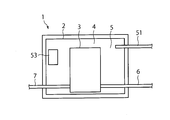
- the container 1 of the solid oxide electrolytic cell stack shown in FIG. 1 has hydrogen present in the gap 4 between the inner surface 2 of the container 1 and the solid oxide electrolytic cell stack 3 accommodated in the container 1.
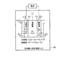
- the solid oxide electrolytic cell stack 3 uses a solid oxide having ionic conductivity as an electrolyte, and a plurality of electrolytic cells formed by sandwiching the solid oxide electrolyte between a hydrogen electrode and an oxygen electrode are stacked. It will be. As shown in FIG. 2, one electrolytic cell 30 is configured by sandwiching an electrolyte 31 made of a solid oxide between a hydrogen electrode 32 and an oxygen electrode 33, and water (H 2 O) is placed on the hydrogen electrode 32 side. ) Is usually supplied in the form of water vapor, and hydrogen is generated by the reaction of H 2 O + 2e ⁇ ⁇ H 2 + O 2 ⁇ at the hydrogen electrode 32, while O 2 ⁇ ⁇ 1/2 O 2 + 2e ⁇ at the oxygen electrode 33. As a result of the generation of oxygen by this reaction, water supplied to the electrolysis cell 30 is electrolyzed into hydrogen and oxygen.
- a plurality of the electrolytic cells 30 can be stacked to form the solid oxide electrolytic cell stack 3.
- a separator (not shown) is further arranged between individual cells as necessary.
- One storage container 1 can store one or a plurality of solid oxide electrolytic cell stacks 3.
- the oxide electrolysis cell stack 3 according to the embodiment shown in FIG. 1 includes a fuel supply pipe 6 that supplies water (water vapor), a hydrogen outflow pipe 7 that flows out the hydrogen generated in the cell stack 3, and, depending on circumstances.
- the cell stack 3 is connected to a power supply line (not shown) for supplying power for electrolyzing water.
- the storage container 1 of the solid oxide electrolytic cell stack is provided with a heater (not shown) for heating the cell stack 3 stored in the container 1. And it is preferable that the storage container 1 is formed with the heat insulating material.
- the oxidant 5 that oxidizes the hydrogen present in the gap 4 inside the container 1 is specifically a fluid oxidant.
- this oxidizing agent is "a substance that assists the combustion of combustible substances (particularly hydrogen)", it may be referred to as “flammable material” in this specification (note that hydrogen gas is Excluded from “flammable materials”).
- flammable material preferably has a higher oxidizing power than air, but this is not essential and may have a lower oxidizing power than air.
- Fluid means a substance or mixture having fluidity under the temperature and pressure conditions when introduced into the container 1. In particular, a gaseous form is preferable.
- examples of particularly preferable fluid-supporting materials include oxygen gas and oxygen-containing gas (for example, air).
- the temperature of the flame-supporting material introduced into the container 1 is high. By this, the temperature fall inside the container 1 by introduction of a flame retardant material can be suppressed.
- the hydrogen leaking into the gap 4 is burned as quickly and reliably as possible.
- the space 4 of the container 1 contains a combustion-supporting substance in an amount more than that necessary for burning leaked hydrogen. Therefore, it is preferable to supply the combustion-supporting substance to the gap 4 at least during the operation of the cell stack 3 (that is, the period in which electrolysis is performed in the cell stack 3). Even when the operation of the cell stack 3 is stopped, it is preferable to supply a combustion-supporting substance to the gap 4 in order to quickly burn the leaked hydrogen.
- the hydrogen leaked from the solid oxide electrolysis cell stack 3 into the gap 4 can be promptly caused by the extremely simple oxidation device 5. It can be burned reliably and gently. This is because when a very small amount of hydrogen leaks, it diffuses mutually with the abundant combustion-supporting substances present in the surrounding area, so that the so-called diffusion combustion occurs stably and continues to be mild. It is presumed that slow combustion is realized. As a result, the stagnation of hydrogen in the gap 4 of the storage container 1 is suppressed, so that the safety of the hydrogen production system and the power storage system can be improved.
- FIG. 3 shows a preferred specific example of a container for an oxide electrolysis cell stack according to an embodiment of the present invention.
- the container 1 of the solid oxide electrolytic cell stack shown in FIG. 3 has hydrogen present in the gap 4 between the inner surface 2 of the container 1 and the solid oxide electrolytic cell stack 3 accommodated in the container 1.
- the oxidant is a solid oxidant 52 disposed in the gap 4.
- the container 1 of the solid oxide electrolytic cell stack shown in FIG. 3 uses the “solid oxidizer 52” and is not shown in FIG. 1 except that the “oxidizer supply device 51” is not provided. It is the same as the container 1 shown. Therefore, except for the solid oxidizing agent 52, the same one as described above can be used for the first embodiment.
- This oxidizer is also “aiding the combustion of combustible substances (especially hydrogen)”.
- the solid combustible material is not particularly limited as long as it can oxidize hydrogen, but an oxide is preferable.
- Particularly preferable examples include iron oxide, nickel oxide, and solid materials containing these.
- Such a solid oxidant 52 can be disposed in the void 4 so as to be in contact with hydrogen existing in the void 4 in the form of particles or powder, or in an arbitrary shape, or in the form of a molded product.
- the inner surface 2 of the container 1 for example, the wall surface, floor surface, or ceiling surface of the container
- the outer wall surface of the cell stack 3 may be attached, coated, or filled into the container 1 with granular or powder. it can.
- Oxidation can be performed.
- the temperature sensor 8 may be disposed on the solid combustion-supporting substance 52. In such an embodiment, the temperature sensor 8 detects a temperature change due to the reaction of the solid combustion-supporting substance with hydrogen, and immediately, the presence or absence of leakage of hydrogen from the electrolytic cell stack 3 and / or hydrogen. The amount of leakage can be accurately determined.
- the container 1 of the oxide type electrolytic cell stack according to the second embodiment hydrogen leaked from the solid oxide type electrolytic cell stack 3 into the gap 4 can be quickly and reliably obtained by an extremely simple oxidation apparatus. Can be gently oxidized. As a result, the stagnation of hydrogen in the gap 4 of the storage container 1 is suppressed, so that the safety of the hydrogen production system and the power storage system can be improved.
- FIG. 4 shows a preferred specific example of a container for an oxide electrolysis cell stack according to an embodiment of the present invention.
- the container 1 of the solid oxide electrolytic cell stack shown in FIG. 4 is the solid oxide shown in FIG. 1 except that a combustion catalyst 53 for burning hydrogen existing in the gap 4 is installed in the gap 4. It has the same contents as the container 1 of the electrolytic cell stack. Therefore, except for the combustion catalyst 53, the same one as described above can be used for the first embodiment.
- the material, shape, installation location, etc. of the combustion catalyst 53 are not particularly limited.
- the material those containing noble metal components such as Pt and Ru are desirable.
- the shape may be particulate, cylindrical or honeycomb, but is not particularly limited.
- the installation location is not particularly limited, examples include the vicinity of the inlet of the combustion-supporting gas pipe 51 and the outer wall surface of the cell stack 3. Thereby, the leaked hydrogen burns and reacts instantaneously, and it is possible to suppress the hydrogen from staying inside the container 1.
- the effects obtained in the first aspect can be achieved more highly and reliably.
- FIG. 5 shows a preferred specific example of a container for an oxide electrolysis cell stack according to an embodiment of the present invention.
- the storage container 1 of the solid oxide electrolytic cell stack shown in FIG. 5 includes hydrogen present in the gap 4 between the inner surface 2 of the container 1 and the solid oxide electrolytic cell stack 3 stored in the container 1. Is contained in the container 1, and the container 1 of the first form shown in FIG.
- the container 1 of the solid oxide electrolytic cell stack further comprising:
- the solid oxide electrolytic cell stack 3 and the oxidant supply device 51 shown in FIG. 5 can be the same as those described above with respect to the first embodiment.
- the temperature sensor 9, the hydrogen concentration sensor 10, the oxygen concentration sensor 11, and the determination device 12 need not always be provided at the same time in the container 1, and can be provided as necessary.
- a sensor or device necessary for acquiring data according to data used when determining the presence or absence of hydrogen leakage from the cell stack 3 and / or the amount of hydrogen leakage Etc. can be provided. That is, for example, when the determination device 12 is provided, when the determination device 12 determines the presence or absence of hydrogen leakage and / or the amount of hydrogen leakage from only the temperature data of the cell stack 3, at least the temperature sensor 9 is used. However, it is not necessary to further include the hydrogen concentration sensor 10, the oxygen concentration sensor 12, other devices, and the like.
- the storage container 1 can be provided with different types of sensors or devices, or a plurality of the same type of sensors or devices.
- the installation location of the temperature sensor 9, the hydrogen concentration sensor 10, the oxygen concentration sensor 11, the determination device 12, and the control device 13 is not particularly limited.
- the various sensors (9, 10, 11) and the container 1 The optimum installation position can be selected as appropriate in consideration of specific contents, type, measurement object, accuracy of measurement results, stability, reliability, and the like.
- the hydrogen concentration sensor 10 is provided at a location where the concentration of leaked hydrogen increases quickly or in the vicinity thereof (for example, preferably, the surface of the cell stack 3, the vicinity thereof, or the ceiling inside the container 1).
- the oxygen concentration sensor 11 can be provided at a location where the oxygen concentration tends to be lean or a location where the average oxygen concentration in the container 1 is obtained.
- the temperature sensor 9, the hydrogen concentration sensor 10, the oxygen concentration sensor 11, and the like are preferably installed inside the storage container 1, but the gas state of the gap 4 can be detected at a level with no necessary accuracy or trouble. Then, it is possible to obtain desired measurement data by installing it outside the container 1 and circulating the gas in the gap 4 therethrough.
- the presence or absence of hydrogen leakage from the solid oxide electrolytic cell stack 3 and / or the amount of hydrogen leakage can be determined.
- the control device 13 is a control device that adjusts the amount of the combustion-supporting substance introduced into the solid oxide electrolytic cell storage container 3 based on the determination by the determination device 12.
- Preferable specific examples of the control device 13 include a supply valve for the combustion-supporting substance and a control valve for controlling the supply amount of the support material. Only one or both of the supply pump and the control valve can be provided.
- the hydrogen leaked from the solid oxide electrolysis cell stack 3 into the gap 4 can be more quickly produced by an extremely simple oxidation apparatus. In addition, it can be reliably and gently oxidized. Thereby, the leaked hydrogen burns and reacts instantaneously, and it is possible to suppress the hydrogen from staying inside the container 1.
- the container 1 of the oxide electrolysis cell stack according to the fourth aspect of the present invention, further comprising various sensors, a determination device, a control device, etc., if necessary, the presence or absence of hydrogen leakage and / or )
- the amount of hydrogen leakage can be determined. Based on this, the supply amount of the combustion-supporting substance can be controlled. As a result, it is possible to effectively suppress a reduction in the amount of the combustion-supporting substance introduced into the container 1 and a decrease in the temperature in the container 1.
- the oxide electrolysis cell stack housing container 1 according to the fourth embodiment may further include a combustion catalyst 53 and a temperature sensor 14 for measuring the temperature of the combustion catalyst 53 as necessary.
- a combustion catalyst 53 the same catalyst as described above can be used for the third embodiment.
- the determination device 12 when the container 1 further includes the combustion catalyst 53 includes (a) the temperature of the solid oxide electrolytic cell stack 3 acquired from the temperature sensor 9 and (b) the hydrogen concentration sensor 10. Selected from the concentration of hydrogen present in the void 4 obtained from (iii) the concentration of oxygen present in the void 4 obtained from the oxygen concentration sensor 11, and (d) the temperature of the combustion catalyst 53 obtained from the temperature sensor 14.
- a determination device 12 that determines the presence or absence of hydrogen leakage from the solid oxide electrolytic cell stack 3 and / or the amount of hydrogen leakage based on one or two or more can be cited.
- the hydrogen leaked from the solid oxide electrolysis cell stack 3 into the gap 4 can be more quickly produced by an extremely simple oxidation apparatus. In addition, it can be reliably and gently oxidized. Thereby, the leaked hydrogen can be instantaneously combusted and reacted, and the hydrogen can be prevented from staying inside the container 1, and the safety of the hydrogen production system and the power storage system can be improved.
- the container 1 of the oxide electrolysis cell stack according to the fourth aspect of the present invention, further comprising various sensors, a determination device, a control device, etc., if necessary, the presence or absence of hydrogen leakage and / or ) It is possible to determine the amount of hydrogen leakage and to control the supply amount of combustion-supporting substances. As a result, it is possible to effectively suppress a reduction in the amount of the combustion-supporting substance introduced into the container 1 and a decrease in the temperature in the container 1.
- FIG. 6 shows a preferred specific example of a container for an oxide electrolysis cell stack according to an embodiment of the present invention.
- the container 1 of the solid oxide electrolytic cell stack shown in FIG. 6 is further added to the container 1 of the first form shown in FIG. (6)
- a flow sensor 15 for measuring the amount of water flowing into the solid oxide electrolytic cell stack 3 a flow sensor 16 for measuring the amount of hydrogen flowing out from the outlet of the solid oxide electrolytic cell stack 3, and a flow sensor 15 and a determination device 17 for determining the presence / absence of hydrogen leakage from the solid oxide electrolytic cell stack 3 and / or the amount of hydrogen leakage based on the calculation of data acquired from the flow sensor 16.
- a solid oxide electrolytic cell further comprising a control device 13 that adjusts the amount of a combustion-supporting substance introduced into the solid oxide electrolytic cell container 3 based on the determination by the determination device 17.
- the stack container 1 is shown. Note that the solid oxide electrolytic cell stack 3 and the oxidant supply device 51 shown in FIG. 6 can be the same as those described above with respect to the first embodiment.
- the determination device 17 the amount of water flowing into the solid oxide electrolytic cell stack acquired from the flow sensor 15 and the amount of hydrogen flowing out from the outlet of the solid oxide electrolytic cell stack acquired from the flow sensor 16.
- the presence or absence of hydrogen leakage from the solid oxide electrolytic cell stack 3 and / or the amount of hydrogen leakage is determined based on the calculation of each data. That is, the determination device 17 leaks hydrogen from the cell stack 3 from the material balance between the raw material (that is, water) supplied to the cell stack 3 and the product (that is, hydrogen and oxygen) that is a decomposition product of water.
- the presence or absence of hydrogen and / or the amount of hydrogen leakage is determined.
- water flowing into the solid oxide electrolytic cell stack is usually water in a water vapor state or a mixture of water in a water vapor state and liquid water (water droplets).
- the control device 13 is a control device that adjusts the amount of the combustion-supporting substance introduced into the solid oxide electrolytic cell storage container 3 based on the determination by the determination device 17.
- the control device 13 include a supply valve for the combustion-supporting substance and a control valve for controlling the supply amount of the support material. Only one or both of the supply pump and the control valve can be provided.
- the oxide electrolytic cell stack housing container 1 according to the fifth embodiment of the present invention further includes a combustion catalyst 53 and a temperature sensor 14 for measuring the temperature of the combustion catalyst 53 as necessary. Can do.
- the combustion catalyst 53 the same catalyst as described above can be used for the third embodiment.
- the oxide electrolysis cell stack container 1 according to the fifth embodiment of the present invention further includes the determination device 12 and sensors described in FIG. 5 and the fourth embodiment in addition to the determination device 17. can do.
- the hydrogen leaked from the solid oxide electrolysis cell stack 3 into the gap 4 can be more quickly obtained by an extremely simple oxidation apparatus. In addition, it can be reliably and gently oxidized.
- the container 1 of the oxide electrolysis cell stack according to the fifth aspect of the present invention further comprising various sensors, a determination device, a control device, etc., the presence or absence of hydrogen leakage and / or ) It is possible to determine the amount of hydrogen leakage and to control the supply amount of combustion-supporting substances. As a result, it is possible to effectively suppress a reduction in the amount of the combustion-supporting substance introduced into the container 1 and a decrease in the temperature in the container 1.
- FIG. 7 is a conceptual diagram of the hydrogen production system and the power storage system.
- the hydrogen production system uses a power generation unit (or electrical energy supply source) A and electric power generated by the power generation unit A to generate hydrogen by decomposing water into hydrogen and oxygen.
- a decomposition part B a decomposition part B.
- the power storage system includes a power generation unit (or electrical energy supply source) A, an electrolysis unit B that uses the power from the power generation unit A to decompose water into hydrogen and oxygen to produce hydrogen, and electrolysis It comprises a storage unit C that stores the hydrogen produced in part B, and a power generation unit D that generates power using the stored hydrogen as a fuel.
- generated in the electrolysis part B can be stored in the storage part E as needed, and this oxygen can also be utilized as a fluid-like combustion support substance.
- the hydrogen production system is a hydrogen production system including an electrolysis unit B including a solid oxide electrolytic cell stack that generates hydrogen by electrolysis of water, and the solid oxide electrolytic cell stack includes: It is stored in the storage container.
- the power storage system includes an electrolysis unit B including a solid oxide electrolytic cell stack that produces hydrogen by electrolysis of water, and a storage unit C that stores hydrogen produced by the electrolysis unit B.
- a power storage system including a power generation unit D that generates power using hydrogen as a fuel, in which a solid oxide electrolytic cell stack is accommodated in a storage container.
- the storage container includes those described in the first to fifth embodiments.
- the stagnation of hydrogen in the space of the container is suppressed, so that the safety of the hydrogen production system and the power storage system can be improved.
Landscapes
- Life Sciences & Earth Sciences (AREA)
- Engineering & Computer Science (AREA)
- Manufacturing & Machinery (AREA)
- Sustainable Development (AREA)
- Sustainable Energy (AREA)
- Chemical & Material Sciences (AREA)
- Chemical Kinetics & Catalysis (AREA)
- Electrochemistry (AREA)
- General Chemical & Material Sciences (AREA)
- Electrolytic Production Of Non-Metals, Compounds, Apparatuses Therefor (AREA)
- Fuel Cell (AREA)
Abstract
固体酸化物形電気化学セルスタックを収容する容器内で水素を速やかに酸化、燃焼させることで、容器内に水素が滞留しない安全な固体酸化物形電解セルスタックの収容容器、水素製造システム、電力貯蔵システムを提供する。固体酸化物形電解セルスタックの収容容器であって、この容器の内面とこの容器に収容された前記固体酸化物形電解セルスタックとの間の空隙に存在する水素を当該容器内部で酸化させる酸化剤を具備する固体酸化物形電解セルスタックの収容容器。
Description
本発明は、固体酸化物形電解セルスタックの収容容器、水素製造システム、電力貯蔵システムに関する。
近年、化石燃料の枯渇、および大気中への二酸化炭素の放出による地球温暖化などの環境問題、エネルギーセキュリティー、などの観点から、太陽光や風力、地熱などに代表される再生可能エネルギーの導入が推進されている。また、二次エネルギーとして、貯蔵や輸送の観点から、水素エネルギーが注目されている。現在、水素の製造方法は、コストや技術の面から、化石燃料を改質する手法が主流となっている。
また、再生可能エネルギーは、近年導入が拡大しているが、その特質上、出力の安定化や電力需要等に対応するように発電量を任意に調整することが難しいという問題点がある。
そこで、再生可能エネルギーから取得した電気エネルギーにより水の電気分解(電解)による水素製造を行い、この水素を一旦貯蔵し、必要なときにこの貯蔵された水素を燃料として発電を行う手法が検討されている。
電解による水素製造方法の中で、高効率な手法として、固体酸化物形電気化学セルを用いた高温水蒸気電解がある。なお、通常、水蒸気電解は、スタックあるいはモジュールなどと称されている、複数のセルを束ね統合化した固体酸化物形電気化学セル群を用いて実施されている。
高温水蒸気電解による水素製造方法は、固体酸化物形電気化学セルを用い、高温(主に500~1000℃の温度域)で水蒸気を電気分解し、水素を製造する方法である。一般に、この固体酸化物形電気化学セルは、固体酸化物(セラミックス)を主構成としていることから、金属材などと比較して強度的に不利であることが多い。このことから、固体酸化物電気化学セルやセルスタックから水素や酸素が周囲環境に拡散しないようにすることが求められる。
本発明が解決しようとする課題は、固体酸化物形電気化学セルスタックを収容する容器内で水素を速やかに酸化、燃焼させることで、容器内に水素が滞留しない安全な固体酸化物形電解セルスタックの収容容器、水素製造システム、電力貯蔵システムを提供することである。
本発明の実施形態による固体酸化物形電解セルスタックの収容容器は、この容器の内面とこの容器に収容された前記固体酸化物形電解セルスタックとの間の空隙に存在する水素を当該容器内部で酸化させる酸化剤を具備するものである。
本発明の実施形態によれば、水の電気分解により水素を製造するシステムおよび電力貯蔵システムにおいて、固体酸化物形電気化学セルスタックを収容する容器内で水素を速やかに酸化、燃焼させることで、容器内に水素が滞留せず、安全性を向上させることができる。
<固体酸化物形電解セルスタックの収容容器>
<< 第一の形態 >>
図1は、本発明の実施形態による酸化物形電解セルスタックの収容容器の好ましい一具体例について示すものである。
図1に示される固体酸化物形電解セルスタックの収容容器1は、この容器1の内面2とこの容器1に収容された固体酸化物形電解セルスタック3との間の空隙4に存在する水素を当該容器1内部で酸化させる酸化剤5を、前記空隙4に導入する酸化剤供給装置51を具備するものである。
<< 第一の形態 >>
図1は、本発明の実施形態による酸化物形電解セルスタックの収容容器の好ましい一具体例について示すものである。
図1に示される固体酸化物形電解セルスタックの収容容器1は、この容器1の内面2とこの容器1に収容された固体酸化物形電解セルスタック3との間の空隙4に存在する水素を当該容器1内部で酸化させる酸化剤5を、前記空隙4に導入する酸化剤供給装置51を具備するものである。
固体酸化物形電解セルスタック3は、電解質としてイオン伝導性を持つ固体酸化物を用い、この固体酸化物電解質を水素極と酸素極とで挟んで構成されてなる電解セルが、複数重ね合わされてなるものである。図2に示されるように、一つの電解セル30は、固体酸化物からなる電解質31を水素極32と酸素極33とで挟んで構成されてなり、この水素極32側に水(H2O)が通常水蒸気の形態で供給され、水素極32における H2O+2e- → H2+O2- の反応によって水素の生成がなされ、一方、酸素極33における O2- → 1/2 O2+2e- の反応によって酸素の生成がなされる結果、電解セル30に供給された水が、水素と酸素へと電気分解されるようになっている。
この電解セル30(単セル)が複数個重ね合わせて、固体酸化物形電解セルスタック3を形成することができる。なお、個々のセルとセルとの間には、必要に応じてさらにセパレータ(図示せず)を配置する。
一つの収容容器1は、固体酸化物形電解セルスタック3を1個または複数個収容することができる。
図1に示される実施形態による酸化物形電解セルスタック3には、水(水蒸気)を供給する燃料供給管6と、セルスタック3で生成された水素を流出させる水素流出管7と、場合により、セルスタック3から酸素を流出させる酸素流出管(図示せず)が接続されている。また、このセルスタック3には、水の電気分解を行うための電力を供給するための電力供給線(図示せず)が接続される。
固体酸化物形電解セルスタックの収容容器1は、容器1内に収容されたセルスタック3を加熱するヒータ(図示せず)が配置されている。そして、収容容器1は、断熱性材料で形成されていることが好ましい。
セルスタック3からの漏えい物(例えば、水素、酸素あるいは水蒸気)がある場合、空隙4に漏出することになる。
固体酸化物形電解セルスタックの収容容器1において、空隙4に存在する水素を当該容器1内部で酸化させる酸化剤5は、具体的には流体状の酸化剤である。なお、この酸化剤は、「可燃性物質(特に水素)の燃焼を助けるもの」であることから、本明細書においては「支燃性材料」と表記する場合がある(尚、水素ガスは、「支燃性材料」から除外する)。
上記「支燃性材料」は、空気以上に酸化力が高いことが好ましいが、これは必須ではなく、空気よりも酸化力が低い場合もありえる。また、「流体」とは、収容容器1に導入する時の温度および圧力条件下において流動性を有する物質ないし混合物を意味する。特に、ガス状であるものが好ましい。
本発明の実施形態において、流体状の支燃性材料として特に好ましいものとしては、例えば、酸素ガスおよび酸素含有ガス(例えば、空気)等を挙げることができる。
そして、収容容器1に導入する支燃性材料質は、温度が高いことが好ましい。このことによって、支燃性材料導入による容器1内部の温度低下を抑制することが出来る。
本発明の実施形態では、空隙4に漏えいした水素を出来るだけ速やかにかつ確実に燃焼させることが好ましい。この観点からは、収容容器1の空隙4には、漏えいした水素の燃焼に必要な量以上の支燃性物質が存在するようにすることが好ましい。したがって、空隙4への支燃性物質の供給は、少なくともセルスタック3の運転中(即ち、セルスタック3において電気分解が行われている期間)は行うことが好ましい。そして、セルスタック3の運転停止中であっても、漏えいした水素の燃焼を速やかに行うためには、空隙4に支燃性物質を供給することが好ましい。
以上の通り、第一の形態による酸化物形電解セルスタックの収容容器1によれば、固体酸化物形電解セルスタック3から空隙4に漏えいした水素を、極めて簡便な酸化装置5によって、速やかに確実にかつ穏やかに燃焼させることができる。これは、水素がごく少量漏えいした時点で、周囲に存在する豊富な支燃性物質との間で相互に拡散しあい、所謂拡散燃焼が安定的に生起し、それが持続することによって、穏やかな緩慢燃焼が実現されることによるものと推測されている。このことによって、収容容器1の空隙4における水素の滞留が抑制されるので、水素製造システムならびに電力貯蔵システムの安全性を向上させることができる。
<< 第二の形態 >>
図3は、本発明の実施形態による酸化物形電解セルスタックの収容容器の好ましい一具体例について、示すものである。
図3に示される固体酸化物形電解セルスタックの収容容器1は、この容器1の内面2とこの容器1に収容された固体酸化物形電解セルスタック3との間の空隙4に存在する水素を当該容器1内部で酸化させる酸化剤を具備するものであって、前記酸化剤が、空隙4内に配置された固体状の酸化剤52であるものである。
図3は、本発明の実施形態による酸化物形電解セルスタックの収容容器の好ましい一具体例について、示すものである。
図3に示される固体酸化物形電解セルスタックの収容容器1は、この容器1の内面2とこの容器1に収容された固体酸化物形電解セルスタック3との間の空隙4に存在する水素を当該容器1内部で酸化させる酸化剤を具備するものであって、前記酸化剤が、空隙4内に配置された固体状の酸化剤52であるものである。
図3に示される固体酸化物形電解セルスタックの収容容器1は、「固体状の酸化剤52」を用いており、そして「酸化剤供給装置51」が設けられていない以外は、図1に示される収容容器1と同様のものである。したがって、固体状の酸化剤52以外は、第一の形態に関して、前記したものと同様なものを用いることができる。この酸化剤も「可燃性物質(特に水素)の燃焼を助けるもの」である。
本発明の実施形態において、固体状の支燃性材料としては、水素を酸化できるものであるならば特に種類を問わないが、酸化物が望ましい。特に好ましいものとしては、例えば、酸化鉄、酸化ニッケル、これらを含む固体材料などが挙げられる。
このような固体状の酸化剤52は、粒状ないし粉体、あるいは任意の形状で、あるいは成形物の形態で、空隙4に存在する水素と接するように、空隙4の中に配置することができる。例えば、容器1の内面2(例えば、容器の壁面、床面あるいは天井面)や、セルスタック3の外壁面に取り付けたり、コーティングしたり、あるいは粒状ないし粉体を容器1内に充填することができる。
本発明の実施形態では、空隙4に存在する水素を速やかにかつ確実に酸化させることが好ましい。この観点からは、収容容器1の空隙4には、漏えいした水素の酸化に必要な量以上の酸素が容器1内に存在させることが好ましい。
このような第二の形態では、セルスタック3の運転中(即ち、セルスタック3において電気分解が行われている期間)はもとより、セルスタック3の運転停止中であっても、漏えいした水素の酸化を行うことができる。
固体状の支燃性物質52には、温度センサ8を配置してもよい。このような実施形態では、固体状の支燃性物質が水素との反応による温度変化を温度センサ8にて検知することにより、直ちに電解セルスタック3からの水素の漏えいの有無および(または)水素の漏えい量を精度良く判定することができるようになる。
以上の第二の形態による酸化物形電解セルスタックの収容容器1によれば、固体酸化物形電解セルスタック3から空隙4に漏えいした水素を、極めて簡便な酸化装置によって、速やかに確実にかつ穏やかに酸化させることができる。このことによって、収容容器1の空隙4における水素の滞留が抑制されるので、水素製造システムならびに電力貯蔵システムの安全性を向上させることができる。
<< 第三の形態 >>
図4は、本発明の実施形態による酸化物形電解セルスタックの収容容器の好ましい一具体例について、示すものである。
図4に示される固体酸化物形電解セルスタックの収容容器1は、空隙4に存在する水素を燃焼させる燃焼触媒53が空隙4に設置されていること以外は、図1に示される固体酸化物形電解セルスタックの収容容器1と同様な内容のものである。したがって、燃焼触媒53以外は、第一の形態に関して、前記したものと同様なものを用いることができる。
図4は、本発明の実施形態による酸化物形電解セルスタックの収容容器の好ましい一具体例について、示すものである。
図4に示される固体酸化物形電解セルスタックの収容容器1は、空隙4に存在する水素を燃焼させる燃焼触媒53が空隙4に設置されていること以外は、図1に示される固体酸化物形電解セルスタックの収容容器1と同様な内容のものである。したがって、燃焼触媒53以外は、第一の形態に関して、前記したものと同様なものを用いることができる。
本発明の実施形態において、燃焼触媒53については、材質や形状、設置場所などは特に問わない。材質に関しては、PtやRuなどの貴金属成分を含むものが望ましい。形状についても、粒子状、円筒状、ハニカム状等が挙げられるが、特に問わない。設置場所についても特に問わないが、支燃性ガス管51の導入口付近や、セルスタック3の外壁面を挙げることができる。これにより、漏えいした水素は瞬時に燃焼・反応し、水素が容器1の内部に滞留することを抑制することができる。
以上の本発明の第三の形態による酸化物形電解セルスタックの収容容器1によれば、前述の第一の形態において得られる効果を、より高度にかつ確実に達成することができる。
<< 第四の形態 >>
図5は、本発明の実施形態による酸化物形電解セルスタックの収容容器の好ましい一具体例について示すものである。
図5に示される固体酸化物形電解セルスタックの収容容器1は、この容器1の内面2とこの容器1に収容された固体酸化物形電解セルスタック3との間の空隙4に存在する水素を当該容器1内部で酸化させる酸化剤を具備するものであって、図1に示される第一の形態の収容容器1に、さらに、
(1)固体酸化物形電解セルスタック3の温度を測定する温度センサ9、
(2)空隙4に存在する水素の濃度を測定する水素濃度センサ10、
(3)空隙4に存在する酸素の濃度を測定する酸素濃度センサ11、
(4)(イ)温度センサ9から取得した固体酸化物形電解セルスタック3の温度、(ロ)水素濃度センサ10から取得した空隙4に存在する水素の濃度、(ハ)酸素濃度センサ11から取得した空隙4に存在する酸素の濃度から選ばれた1つまたは2つ以上をもとに、固体酸化物形電解セルスタック3からの水素の漏えいの有無および(または)水素の漏えい量を判定する判定装置12、
(5)判定装置12による判定をもとに、固体酸化物形電解セル収容容器3の内部に導入される支燃性物質の量を調整する制御装置13
をさらに具備する固体酸化物形電解セルスタックの収容容器1を示すものである。
図5は、本発明の実施形態による酸化物形電解セルスタックの収容容器の好ましい一具体例について示すものである。
図5に示される固体酸化物形電解セルスタックの収容容器1は、この容器1の内面2とこの容器1に収容された固体酸化物形電解セルスタック3との間の空隙4に存在する水素を当該容器1内部で酸化させる酸化剤を具備するものであって、図1に示される第一の形態の収容容器1に、さらに、
(1)固体酸化物形電解セルスタック3の温度を測定する温度センサ9、
(2)空隙4に存在する水素の濃度を測定する水素濃度センサ10、
(3)空隙4に存在する酸素の濃度を測定する酸素濃度センサ11、
(4)(イ)温度センサ9から取得した固体酸化物形電解セルスタック3の温度、(ロ)水素濃度センサ10から取得した空隙4に存在する水素の濃度、(ハ)酸素濃度センサ11から取得した空隙4に存在する酸素の濃度から選ばれた1つまたは2つ以上をもとに、固体酸化物形電解セルスタック3からの水素の漏えいの有無および(または)水素の漏えい量を判定する判定装置12、
(5)判定装置12による判定をもとに、固体酸化物形電解セル収容容器3の内部に導入される支燃性物質の量を調整する制御装置13
をさらに具備する固体酸化物形電解セルスタックの収容容器1を示すものである。
なお、図5に示される固体酸化物形電解セルスタック3および酸化剤供給装置51は、第一の形態に関して、前記したものと同様なものを用いることができる。
温度センサ9、水素濃度センサ10、酸素濃度センサ11、判定装置12は、収容容器1に常に同時に設ける必要はなく、それぞれ、必要に応じて設けることができる。
好ましくは、例えば、判定装置12において、セルスタック3からの水素の漏えいの有無および(または)水素の漏えい量を判定する際に利用するデータに応じて、そのデータの取得に必要なセンサないし装置等を設けることができる。即ち、例えば、判定装置12を設ける場合において、この判定装置12がセルスタック3の温度のデータのみから水素の漏えいの有無および(または)水素の漏えい量を判定する際には、少なくとも温度センサ9と判定装置12の両者を具備する必要があるが、それらに加えて水素濃度センサ10や酸素濃度センサ12、その他の装置等などを更に具備することまでは要しない。
収容容器1には、異なる種類のセンサないし装置を設けることができるし、同一種類のセンサないし装置を複数個設けることができる。
上記の温度センサ9、水素濃度センサ10、酸素濃度センサ11、判定装置12、制御装置13の設置箇所は、特に限定はなく、例えば、各種センサ(9、10、11)や収容容器1の具体的な内容、種類、測定対象、測定結果の正確性、安定性、信頼性等を考慮して、適宜最適な設置位置を選定することができる。好ましくは、例えば、水素濃度センサ10は、漏えいした水素の濃度がいち早く高まる箇所あるいはその近傍(例えば、好ましくは、セルスタック3の表面、その近傍付近、あるいは容器1内部の天井付近等)に設けることができ、例えば、酸素濃度センサ11は、酸素濃度が希薄になりがちな箇所や、あるいは容器1内において平均的な酸素濃度となる箇所等に設けることができる。
一般的に、温度センサ9、水素濃度センサ10、酸素濃度センサ11等は、収容容器1の内部に設置することが好ましいが、隙間4のガス状態を必要な精度あるいは支障がないレベルで検知できるならば、収容容器1の外部に設置し、そこに隙間4のガスを流通させることによって所望の測定データを得ることができる。
判定装置12では、(イ)固体酸化物形電解セルスタック3の温度、(ロ)空隙4に存在する水素の濃度、(ハ)空隙4に存在する酸素の濃度から選ばれたいずれか1つまたは2つ以上をもとに、前記固体酸化物形電解セルスタック3からの水素の漏えいの有無および(または)水素の漏えい量を判定することができる。これらの中では、(ロ)の「空隙4に存在する水素の濃度」から、水素の漏えいの有無および(または)水素の漏えい量を判定するのが好適である。
制御装置13は、前記の判定装置12による判定をもとに、固体酸化物形電解セル収容容器3の内部に導入される支燃性物質の量を調整する制御装置である。この制御装置13の好ましい具体例としては、支燃性物質の供給ポンプおよび支燃性物質の供給量を制御する制御弁等を挙げることができる。供給ポンプおよび制御弁は、どちらか片方のみを設けることができるし、両方を設けることができる。
以上の本発明の第四の形態による酸化物形電解セルスタックの収容容器1によれば、固体酸化物形電解セルスタック3から空隙4に漏えいした水素を、極めて簡便な酸化装置によって、より速やかに、確実にかつ穏やかに酸化させることができる。これにより、漏えいした水素は瞬時に燃焼・反応し、水素が容器1の内部に滞留することを抑制することができる。
そして、必要に応じて、各種センサ、判定装置、制御装置等を更に具備する本発明の第四の形態による酸化物形電解セルスタックの収容容器1によれば、水素の漏えいの有無および(または)水素の漏えい量の判定を行うことができる。そして、それに基づいて、支燃性物質の供給量の制御を行うことができる。このことにより、容器1への支燃性物質の導入量の削減ならびに容器1内の温度の低下を効果的に抑制することができる。
<<< 第四の形態の他の具体例 >>>
上記の第四の形態による酸化物形電解セルスタック収容容器1は、必要に応じて、燃焼触媒53、ならびにこの燃焼触媒53の温度を測定する温度センサ14を、さらに具備することができる。なお、燃焼触媒53としては、第三の形態に関して、前記したものと同様なものを用いることができる。
上記の第四の形態による酸化物形電解セルスタック収容容器1は、必要に応じて、燃焼触媒53、ならびにこの燃焼触媒53の温度を測定する温度センサ14を、さらに具備することができる。なお、燃焼触媒53としては、第三の形態に関して、前記したものと同様なものを用いることができる。
このように、収容容器1がさらに燃焼触媒53を具備する場合の判定装置12としては、(イ)温度センサ9から取得した固体酸化物形電解セルスタック3の温度、(ロ)水素濃度センサ10から取得した空隙4に存在する水素の濃度、(ハ)酸素濃度センサ11から取得した前記空隙4に存在する酸素の濃度、(ニ)温度センサ14から取得した燃焼触媒53の温度から選ばれた1つまたは2つ以上をもとに、固体酸化物形電解セルスタック3からの水素の漏えいの有無および(または)水素の漏えい量を判定する判定装置12を挙げることができる。
以上の本発明の第四の形態による酸化物形電解セルスタックの収容容器1によれば、固体酸化物形電解セルスタック3から空隙4に漏えいした水素を、極めて簡便な酸化装置によって、より速やかに、確実にかつ穏やかに酸化させることができる。これにより、漏えいした水素は瞬時に燃焼・反応し、水素が容器1の内部に滞留することを抑制することができ、水素製造システムならびに電力貯蔵システムの安全性を向上させることができる。
そして、必要に応じて、各種センサ、判定装置、制御装置等を更に具備する本発明の第四の形態による酸化物形電解セルスタックの収容容器1によれば、水素の漏えいの有無および(または)水素の漏えい量の判定と、支燃性物質の供給量の制御を行うことができる。このことにより、容器1への支燃性物質の導入量の削減ならびに容器1内の温度の低下を効果的に抑制することができる。
<< 第五の形態 >>
図6は、本発明の実施形態による酸化物形電解セルスタックの収容容器の好ましい一具体例について示すものである。
図6に示される固体酸化物形電解セルスタックの収容容器1は、具体的には、図1に示される第一の形態の収容容器1に、さらに、
(6)固体酸化物形電解セルスタック3に流入する水の量を測定する流量センサ15、固体酸化物形電解セルスタック3の流出口から流出する水素の量を測定する流量センサ16、流量センサ15と流量センサ16とから取得したデータの演算をもとに、前記固体酸化物形電解セルスタック3からの水素の漏えいの有無および(または)水素の漏えい量を判定する判定装置17、
(7)判定装置17による判定をもとに、固体酸化物形電解セル収容容器3の内部に導入される支燃性物質の量を調整する制御装置13をさらに具備する固体酸化物形電解セルスタックの収容容器1を示すものである。
なお、図6に示される固体酸化物形電解セルスタック3および酸化剤供給装置51は、第一の形態に関して、前記したものと同様なものを用いることができる。
図6は、本発明の実施形態による酸化物形電解セルスタックの収容容器の好ましい一具体例について示すものである。
図6に示される固体酸化物形電解セルスタックの収容容器1は、具体的には、図1に示される第一の形態の収容容器1に、さらに、
(6)固体酸化物形電解セルスタック3に流入する水の量を測定する流量センサ15、固体酸化物形電解セルスタック3の流出口から流出する水素の量を測定する流量センサ16、流量センサ15と流量センサ16とから取得したデータの演算をもとに、前記固体酸化物形電解セルスタック3からの水素の漏えいの有無および(または)水素の漏えい量を判定する判定装置17、
(7)判定装置17による判定をもとに、固体酸化物形電解セル収容容器3の内部に導入される支燃性物質の量を調整する制御装置13をさらに具備する固体酸化物形電解セルスタックの収容容器1を示すものである。
なお、図6に示される固体酸化物形電解セルスタック3および酸化剤供給装置51は、第一の形態に関して、前記したものと同様なものを用いることができる。
判定装置17では、流量センサ15から取得された固体酸化物形電解セルスタックに流入する水の量と、流量センサ16から取得された固体酸化物形電解セルスタックの流出口から流出する水素の量との、それぞれのデータの演算をもとに、固体酸化物形電解セルスタック3からの水素の漏えいの有無および(または)水素の漏えい量を判定する。すなわち、判定装置17では、セルスタック3に供給された原料(即ち、水)と、水の分解物である生成物(即ち、水素と酸素)との物質収支から、セルスタック3からの水素漏えいの有無および(または)水素の漏えい量の判定がなされる。ここで、「固体酸化物形電解セルスタックに流入する水」とは、通常、水蒸気の状態にある水、あるいは水蒸気状態にある水と液状(水滴)にある水との混合物である。
固体酸化物形電解セルスタック3からの水素の漏えいの有無および(または)水素の漏えい量を判定する際は、流量センサ15および流量センサ16から取得されたデータをもとに、例えば容器1の具体的内容やセルスタック3で行われる電気分解の運転状況等を踏まえ、必要に応じて適宜定められた条件パラメータ等を加味して適宜行うことができる。
制御装置13は、前記の判定装置17による判定をもとに、固体酸化物形電解セル収容容器3の内部に導入される支燃性物質の量を調整する制御装置である。この制御装置13の好ましい具体例としては、支燃性物質の供給ポンプおよび支燃性物質の供給量を制御する制御弁等を挙げることができる。供給ポンプおよび制御弁は、どちらか片方のみを設けることができるし、両方を設けることができる。
<<< 第五の形態の他の具体例 >>>
上記の本発明の第五の実施形態による酸化物形電解セルスタック収容容器1は、必要に応じて、燃焼触媒53、ならびにこの燃焼触媒53の温度を測定する温度センサ14を、さらに具備することができる。なお、燃焼触媒53としては、第三の形態に関して、前記したものと同様なものを用いることができる。
上記の本発明の第五の実施形態による酸化物形電解セルスタック収容容器1は、必要に応じて、燃焼触媒53、ならびにこの燃焼触媒53の温度を測定する温度センサ14を、さらに具備することができる。なお、燃焼触媒53としては、第三の形態に関して、前記したものと同様なものを用いることができる。
さらに、本発明の第五の実施形態による酸化物形電解セルスタック収容容器1は、判定装置17に加えて、図5および第四の実施形態に記載された判定装置12やセンサ等をさらに具備することができる。
以上の本発明の第五の形態による酸化物形電解セルスタックの収容容器1によれば、固体酸化物形電解セルスタック3から空隙4に漏えいした水素を、極めて簡便な酸化装置によって、より速やかに、確実にかつ穏やかに酸化させることができる。
そして、必要に応じて、各種センサ、判定装置、制御装置等を更に具備する本発明の第五の形態による酸化物形電解セルスタックの収容容器1によれば、水素の漏えいの有無および(または)水素の漏えい量の判定と、支燃性物質の供給量の制御を行うことができる。このことにより、容器1への支燃性物質の導入量の削減ならびに容器1内の温度の低下を効果的に抑制することができる。
<水素製造システムおよび電力貯蔵システム>
図7は、水素製造システムおよび電力貯蔵システムの概念図である。
図7に示されるように、水素製造システムは、発電部(ないし電気エネルギー供給源)Aと、その発電部Aで発電した電力を用い、水を水素と酸素に分解して水素を製造する電気分解部Bとを具備してなるものである。また、電力貯蔵システムは、発電部(ないし電気エネルギー供給源)Aと、この発電部Aからの電力を用い、水を水素と酸素に分解して水素を製造する電気分解部Bと、電気分解部Bで製造された水素を貯蔵する貯蔵部Cと、貯蔵された水素を燃料として発電を行う発電部Dとを具備してなるものである。なお、電気分解部Bで生成された酸素は、必要に応じて、貯蔵部Eで貯蔵することができるし、この酸素を流体状の支燃性物質として利用することもできる。
図7は、水素製造システムおよび電力貯蔵システムの概念図である。
図7に示されるように、水素製造システムは、発電部(ないし電気エネルギー供給源)Aと、その発電部Aで発電した電力を用い、水を水素と酸素に分解して水素を製造する電気分解部Bとを具備してなるものである。また、電力貯蔵システムは、発電部(ないし電気エネルギー供給源)Aと、この発電部Aからの電力を用い、水を水素と酸素に分解して水素を製造する電気分解部Bと、電気分解部Bで製造された水素を貯蔵する貯蔵部Cと、貯蔵された水素を燃料として発電を行う発電部Dとを具備してなるものである。なお、電気分解部Bで生成された酸素は、必要に応じて、貯蔵部Eで貯蔵することができるし、この酸素を流体状の支燃性物質として利用することもできる。
水素製造システムは、水の電気分解によって水素を生成させる固体酸化物形電解セルスタックを含んでなる電気分解部Bを具備してなる水素製造システムであって、固体酸化物形電解セルスタックが、収容容器に収容されているものである。
電力貯蔵システムは、水の電気分解によって水素を製造する固体酸化物形電解セルスタックを含んでなる電気分解部Bと、電気分解部Bで製造された水素を貯蔵する貯蔵部Cと、貯蔵された水素を燃料として発電を行う発電部Dとを具備してなる電力貯蔵システムであって、固体酸化物形電解セルスタックが、収容容器に収容されているものである。
ここで、収容容器の好ましい具体例には、第一の形態~第五の形態において記載されたものが包含される。
本発明の実施形態による水素製造システムおよび電力貯蔵システムでは、収容容器の空隙における水素の滞留が抑制されるので、水素製造システムならびに電力貯蔵システムの安全性を向上させることができる。
以上、本発明のいくつかの実施形態を説明したが、これらの実施形態は、例として提示したものであり、発明の範囲を限定することは意図していない。これら新規な実施形態は、その他の様々な形態で実施することが可能であり、発明の要旨を逸脱しない範囲で、種々の省略、置き換え、変更を行うことができる。これらの実施形態やその変形例は、発明の範囲や要旨に含まれると共に、特許請求の範囲に記載された発明とその均等の範囲に含まれる。
1:収容容器、3:固体酸化物形電解セルスタック、30:電解セル、31:固体酸化物電解質、32:水素極、33:酸素極、4:空隙、51:流体状の酸化剤の供給装置、52:固体状の酸化剤、53:燃焼触媒、6:燃料供給管、7:水素流出管、8:温度センサ、9:温度センサ、10:水素濃度センサ、11:酸素濃度センサ、12:判定装置、13:制御装置、14:温度センサ、15:流量センサ、16:流量センサ、17:判定装置、A:発電部、B:電気分解部、C:水素貯蔵部、D:発電部、E:酸素貯蔵部
Claims (9)
- 固体酸化物形電解セルスタックの収容容器であって、
この容器の内面とこの容器に収容された前記固体酸化物形電解セルスタックとの間の空隙に存在する水素を当該容器内部で酸化させる酸化剤を具備する、固体酸化物形電解セルスタックの収容容器。 - 前記収容容器が、流体状の前記酸化剤を前記空隙に導入する酸化剤供給装置をさらに具備する、請求項1に記載の収容容器。
- 前記酸化剤が、前記空隙内に配置された固体状の酸化剤である、請求項1に記載の収容容器。
- 前記空隙に設置された、水素を燃焼させる燃焼触媒をさらに具備する、請求項2に記載の収容容器。
- 前記固体酸化物形電解セルスタックの温度、前記空隙に存在する水素の濃度、前記空隙に存在する酸素の濃度、前記固体状の支燃性物質の温度、前記燃焼触媒の温度から選ばれるいずれか1つまたは2つ以上をもとに、前記固体酸化物形電解セルスタックからの水素の漏えいの有無および水素の漏えい量のうち少なくともひとつを判定する判定装置をさらに具備する、請求項1~4のいずれか1項に記載の収容容器。
- 前記固体酸化物形電解セルスタックに流入する水の量と、前記固体酸化物形電解セルスタックの流出口から流出する水素の量との、それぞれのデータの演算をもとに、前記固体酸化物形電解セルスタックからの水素の漏えいの有無および水素の漏えい量のうち少なくともひとつを判定する判定装置をさらに具備する、請求項1~5のいずれか1項に記載の収容容器。
- 前記判定装置による判定をもとに、前記固体酸化物形電解セル収容容器の内部に導入される前記支燃性物質の量を調整する制御装置をさらに具備する、請求項5または請求項6に記載の収容容器。
- 水の電気分解によって水素を生成させる固体酸化物形電解セルスタックを含んでなる電解部を具備してなる水素製造システムであって、
前記固体酸化物形電解セルスタックが、請求項1~7のいずれか1項に記載の収容容器に収容されている、水素製造システム。 - 水の電気分解によって水素を製造する固体酸化物形電解セルスタックを含んでなる電解部と、前記電解部で製造された水素を貯蔵する貯蔵部と、前記貯蔵された水素を燃料として発電を行う発電部とを具備してなる電力貯蔵システムであって、
前記固体酸化物形電解セルスタックが、請求項1~7のいずれか1項に記載の収容容器に収容されている、電力貯蔵システム。
Priority Applications (2)
| Application Number | Priority Date | Filing Date | Title |
|---|---|---|---|
| PCT/JP2016/057389 WO2017154137A1 (ja) | 2016-03-09 | 2016-03-09 | 固体酸化物形電解セルスタックの収容容器、水素製造システム、電力貯蔵システム |
| JP2018503916A JP6725641B2 (ja) | 2016-03-09 | 2016-03-09 | 固体酸化物形電解セルスタックの収容容器、水素製造システム、電力貯蔵システム |
Applications Claiming Priority (1)
| Application Number | Priority Date | Filing Date | Title |
|---|---|---|---|
| PCT/JP2016/057389 WO2017154137A1 (ja) | 2016-03-09 | 2016-03-09 | 固体酸化物形電解セルスタックの収容容器、水素製造システム、電力貯蔵システム |
Publications (1)
| Publication Number | Publication Date |
|---|---|
| WO2017154137A1 true WO2017154137A1 (ja) | 2017-09-14 |
Family
ID=59789229
Family Applications (1)
| Application Number | Title | Priority Date | Filing Date |
|---|---|---|---|
| PCT/JP2016/057389 Ceased WO2017154137A1 (ja) | 2016-03-09 | 2016-03-09 | 固体酸化物形電解セルスタックの収容容器、水素製造システム、電力貯蔵システム |
Country Status (2)
| Country | Link |
|---|---|
| JP (1) | JP6725641B2 (ja) |
| WO (1) | WO2017154137A1 (ja) |
Cited By (1)
| Publication number | Priority date | Publication date | Assignee | Title |
|---|---|---|---|---|
| WO2023279128A1 (de) * | 2021-07-06 | 2023-01-12 | Avl List Gmbh | Brennstoffzellensystem mit einer rekombinationsvorrichtung |
Citations (5)
| Publication number | Priority date | Publication date | Assignee | Title |
|---|---|---|---|---|
| JP2006162243A (ja) * | 2004-11-10 | 2006-06-22 | Osaka Gas Co Ltd | 水素ガス除去装置 |
| JP2010232165A (ja) * | 2009-02-16 | 2010-10-14 | Toshiba Corp | 水素電力貯蔵システムおよび水素電力貯蔵方法 |
| WO2012128368A1 (ja) * | 2011-03-24 | 2012-09-27 | Jx日鉱日石エネルギー株式会社 | 燃料電池モジュール |
| JP2013175448A (ja) * | 2012-01-23 | 2013-09-05 | Ngk Spark Plug Co Ltd | 燃料電池システム |
| JP2013199675A (ja) * | 2012-03-23 | 2013-10-03 | Tokyo Gas Co Ltd | 電気化学装置および蓄電システム |
Family Cites Families (6)
| Publication number | Priority date | Publication date | Assignee | Title |
|---|---|---|---|---|
| US4801369A (en) * | 1987-06-29 | 1989-01-31 | Westinghouse Electric Corp. | Preventing fluids in leakable enclosures from intermixing |
| JP2009174018A (ja) * | 2008-01-25 | 2009-08-06 | Toshiba Corp | 水素製造装置 |
| JP5181012B2 (ja) * | 2010-03-30 | 2013-04-10 | 本田技研工業株式会社 | 水電解システム及びその運転方法 |
| JP5514266B2 (ja) * | 2012-06-25 | 2014-06-04 | 株式会社東芝 | 水蒸気電解装置及び水蒸気電解方法 |
| JP6289828B2 (ja) * | 2013-07-17 | 2018-03-07 | 株式会社東芝 | 水素製造装置 |
| CN105393392B (zh) * | 2013-07-24 | 2018-04-10 | 京瓷株式会社 | 混合动力装置以及混合动力系统 |
-
2016
- 2016-03-09 WO PCT/JP2016/057389 patent/WO2017154137A1/ja not_active Ceased
- 2016-03-09 JP JP2018503916A patent/JP6725641B2/ja active Active
Patent Citations (5)
| Publication number | Priority date | Publication date | Assignee | Title |
|---|---|---|---|---|
| JP2006162243A (ja) * | 2004-11-10 | 2006-06-22 | Osaka Gas Co Ltd | 水素ガス除去装置 |
| JP2010232165A (ja) * | 2009-02-16 | 2010-10-14 | Toshiba Corp | 水素電力貯蔵システムおよび水素電力貯蔵方法 |
| WO2012128368A1 (ja) * | 2011-03-24 | 2012-09-27 | Jx日鉱日石エネルギー株式会社 | 燃料電池モジュール |
| JP2013175448A (ja) * | 2012-01-23 | 2013-09-05 | Ngk Spark Plug Co Ltd | 燃料電池システム |
| JP2013199675A (ja) * | 2012-03-23 | 2013-10-03 | Tokyo Gas Co Ltd | 電気化学装置および蓄電システム |
Cited By (3)
| Publication number | Priority date | Publication date | Assignee | Title |
|---|---|---|---|---|
| WO2023279128A1 (de) * | 2021-07-06 | 2023-01-12 | Avl List Gmbh | Brennstoffzellensystem mit einer rekombinationsvorrichtung |
| AT525203A1 (de) * | 2021-07-06 | 2023-01-15 | Avl List Gmbh | Brennstoffzellensystem mit einer Rekombinationsvorrichtung |
| AT525203B1 (de) * | 2021-07-06 | 2023-03-15 | Avl List Gmbh | Brennstoffzellensystem mit einer Rekombinationsvorrichtung |
Also Published As
| Publication number | Publication date |
|---|---|
| JPWO2017154137A1 (ja) | 2019-02-14 |
| JP6725641B2 (ja) | 2020-07-22 |
Similar Documents
| Publication | Publication Date | Title |
|---|---|---|
| JP2018087501A (ja) | 複合発電システムの制御装置、複合発電システム、複合発電システムの制御方法および複合発電システムの制御プログラム | |
| KR20190098906A (ko) | 연료 전지 시스템 및 복합 발전 시스템, 그리고 연료 전지 시스템의 제어 방법 | |
| US9685672B2 (en) | Hydrogen generation apparatus, fuel cell system including the same, method of operating hydrogen generation apparatus and method of operating fuel cell system | |
| JP2010086917A (ja) | 燃料電池システム | |
| JP6494981B2 (ja) | 固体酸化物形燃料電池システム及びこれを備える複合発電システム、並びに、固体酸化物形燃料電池システムの停止方法 | |
| JP5601945B2 (ja) | 固体酸化物形燃料電池の起動方法 | |
| JP2013191299A (ja) | 燃料電池システム | |
| JP6574893B2 (ja) | 水素漏えい防止システム、水素漏えい防止方法水素製造システム、電力貯蔵システム | |
| JP6352147B2 (ja) | 複合発電システム及び複合発電システムの制御方法 | |
| CN101816090A (zh) | 燃料电池设备 | |
| JP6725641B2 (ja) | 固体酸化物形電解セルスタックの収容容器、水素製造システム、電力貯蔵システム | |
| JP6486649B2 (ja) | 複合発電システム及び複合発電システムの制御方法 | |
| KR101265198B1 (ko) | 연료 개질장치 | |
| JP6239229B2 (ja) | 燃料電池システムおよび燃料電池運転方法 | |
| JP5114086B2 (ja) | 固体酸化物型燃料電池モジュールおよびその起動方法 | |
| JP2013082603A (ja) | 水素生成装置およびその水素生成装置を用いた燃料電池システム | |
| JP6424492B2 (ja) | 燃料電池システム | |
| JP2014089890A (ja) | 燃料電池式発電装置及びコージェネレーションシステム | |
| JP5850769B2 (ja) | 燃料電池システム | |
| JP2007194098A (ja) | 燃料電池発電システム | |
| JP6632911B2 (ja) | 燃料電池及び燃料電池複合発電システム並びに燃料電池の停止方法 | |
| JP5147198B2 (ja) | 燃料電池システム | |
| KR101744504B1 (ko) | 고체산화물연료전지시스템의 급속 시동 장치 및 이를 이용한 고체산화물연료전지시스템의 급속 시동 방법 | |
| JP2015082408A (ja) | 固体酸化物形燃料電池システムおよび固体酸化物形燃料電池システムの停止方法 | |
| JP2014165009A (ja) | セルスタックの評価装置、及びその評価方法 |
Legal Events
| Date | Code | Title | Description |
|---|---|---|---|
| WWE | Wipo information: entry into national phase |
Ref document number: 2018503916 Country of ref document: JP |
|
| NENP | Non-entry into the national phase |
Ref country code: DE |
|
| 121 | Ep: the epo has been informed by wipo that ep was designated in this application |
Ref document number: 16893469 Country of ref document: EP Kind code of ref document: A1 |
|
| 122 | Ep: pct application non-entry in european phase |
Ref document number: 16893469 Country of ref document: EP Kind code of ref document: A1 |