WO2017150352A1 - ナール構造付きフィルム及び製造方法 - Google Patents
ナール構造付きフィルム及び製造方法 Download PDFInfo
- Publication number
- WO2017150352A1 WO2017150352A1 PCT/JP2017/006960 JP2017006960W WO2017150352A1 WO 2017150352 A1 WO2017150352 A1 WO 2017150352A1 JP 2017006960 W JP2017006960 W JP 2017006960W WO 2017150352 A1 WO2017150352 A1 WO 2017150352A1
- Authority
- WO
- WIPO (PCT)
- Prior art keywords
- film
- knurl
- knurled
- nar
- back roll
- Prior art date
- Legal status (The legal status is an assumption and is not a legal conclusion. Google has not performed a legal analysis and makes no representation as to the accuracy of the status listed.)
- Ceased
Links
Images


Classifications
-
- B—PERFORMING OPERATIONS; TRANSPORTING
- B29—WORKING OF PLASTICS; WORKING OF SUBSTANCES IN A PLASTIC STATE IN GENERAL
- B29C—SHAPING OR JOINING OF PLASTICS; SHAPING OF MATERIAL IN A PLASTIC STATE, NOT OTHERWISE PROVIDED FOR; AFTER-TREATMENT OF THE SHAPED PRODUCTS, e.g. REPAIRING
- B29C59/00—Surface shaping of articles, e.g. embossing; Apparatus therefor
- B29C59/02—Surface shaping of articles, e.g. embossing; Apparatus therefor by mechanical means, e.g. pressing
- B29C59/04—Surface shaping of articles, e.g. embossing; Apparatus therefor by mechanical means, e.g. pressing using rollers or endless belts
-
- B—PERFORMING OPERATIONS; TRANSPORTING
- B29—WORKING OF PLASTICS; WORKING OF SUBSTANCES IN A PLASTIC STATE IN GENERAL
- B29C—SHAPING OR JOINING OF PLASTICS; SHAPING OF MATERIAL IN A PLASTIC STATE, NOT OTHERWISE PROVIDED FOR; AFTER-TREATMENT OF THE SHAPED PRODUCTS, e.g. REPAIRING
- B29C59/00—Surface shaping of articles, e.g. embossing; Apparatus therefor
- B29C59/002—Component parts, details or accessories; Auxiliary operations
-
- B—PERFORMING OPERATIONS; TRANSPORTING
- B29—WORKING OF PLASTICS; WORKING OF SUBSTANCES IN A PLASTIC STATE IN GENERAL
- B29C—SHAPING OR JOINING OF PLASTICS; SHAPING OF MATERIAL IN A PLASTIC STATE, NOT OTHERWISE PROVIDED FOR; AFTER-TREATMENT OF THE SHAPED PRODUCTS, e.g. REPAIRING
- B29C59/00—Surface shaping of articles, e.g. embossing; Apparatus therefor
- B29C59/02—Surface shaping of articles, e.g. embossing; Apparatus therefor by mechanical means, e.g. pressing
- B29C59/022—Surface shaping of articles, e.g. embossing; Apparatus therefor by mechanical means, e.g. pressing characterised by the disposition or the configuration, e.g. dimensions, of the embossments or the shaping tools therefor
-
- B—PERFORMING OPERATIONS; TRANSPORTING
- B29—WORKING OF PLASTICS; WORKING OF SUBSTANCES IN A PLASTIC STATE IN GENERAL
- B29L—INDEXING SCHEME ASSOCIATED WITH SUBCLASS B29C, RELATING TO PARTICULAR ARTICLES
- B29L2007/00—Flat articles, e.g. films or sheets
- B29L2007/002—Panels; Plates; Sheets
Definitions
- the present invention relates to a film with a knurled structure and a method for producing the same.
- a concavo-convex structure In the production of a film, it is known to give a concavo-convex structure to a partial region of the film surface for various purposes. For example, it is known to provide a concavo-convex structure at the end of the film in order to improve the handleability of the film when winding a long film.
- a concavo-convex structure is sometimes called a knurl structure, and a process for imparting such a knurl structure is called by a name such as a knurling process.
- Patent Documents 1 and 2 As specific examples of the knurling operation, various methods such as a method of contacting a film having a knurl structure with a film and a method of irradiating the film with laser light are known (for example, Patent Documents 1 and 2). .
- a film with a nar structure Prior to winding a film into a film roll, a film with a nar structure is provided on the surface of the film to form a film with a nar structure, thereby generating scratches due to friction between the films in the film roll, and blocking the film (film Undesirable phenomena such as a phenomenon in which the surfaces of the overlapping films adhere to the roll are reduced, and the handleability of the film can be improved.
- the height of the knurled structure changes. Specifically, after imparting a nar structure, the height of the nar structure may decrease over time. Such a phenomenon is also referred to as a knurl return.
- a phenomenon is also referred to as a knurl return.
- the knurl return occurs, the effect of the knurl structure is impaired, and an undesired phenomenon such as blocking may occur. Therefore, there is a need for a technique for reducing such a knurled return.
- An object of the present invention is to provide a film with a knurl structure having a knurl structure with less knurl return and a method for producing a knurl structure with a knurl structure with less knurl return.
- the present inventor has found that the above-described problems can be solved by forming a unit having a specific shape as the nar structure unit constituting the nar structure.
- the present inventor has also found that the above-mentioned production can be easily performed by giving a knurled structure by a process using a combination of a back roll and a knurling and by making the conditions in the process specific. It was.
- the present invention has been completed based on such findings. That is, according to the present invention, the following [A1] to [A3] and [B1] to [B10] are provided.
- the production methods [B1] to [B10] can be used to produce a film with a knurled structure [A1] to [A3].
- a film with a long knurl structure The film with the knurl structure includes a knurl area provided at an end in the width direction,
- the nar region has a plurality of nar structural units, Each of the nar structural units has one concave portion and a top portion that is formed around the concave portion and is continuous in a bowl shape.
- the nar structure unit satisfies the following formula (1): 1.05 ⁇ AvHmax / AvHmin ⁇ 30 (1)
- AvHmax is an average value of Hmax of the plurality of nar structural units
- Hmax is the maximum height of the top of each of the nar structural units
- AvHmin is an average value of Hmin of a plurality of the nar structural units
- Hmin is a minimum height of the top of each of the nar structural units.
- [A2] The film with a knurled structure according to [A1], in which the distribution of the position of the top Tmax that gives the maximum height Hmax of the top in the knurled unit is unevenly distributed in the longitudinal direction of the film with the knurled structure.
- [A3] The knurl structure according to [A1] or [A2], wherein the distribution of the position of the top portion Tmax giving the maximum height Hmax of the knurl structure is unevenly distributed in the width direction of the film with the knurl structure.
- a rotating back roll is brought into contact with one surface of a long film to be conveyed to support the film, and a rotating knurl is pressed against the other surface, thereby causing the film to move in the width direction.
- a shaping process to form a knurl structure at the end The manufacturing method of the film with a knurled structure whose peripheral speed of the said knurl is faster than the peripheral speed of the said back roll.
- the knurled peripheral speed Vr (m / min) and the back roll peripheral speed Vb (m / min) satisfy the following formula (2): Production method.
- the knurl is arranged so that the rotation axis thereof is inclined with respect to the width direction of the film, and the inclination is such that the rotation axis is close to the film on the inner side in the width direction of the film,
- the method for producing a film with a knurled structure according to any one of [B1] to [B4], wherein the rotation axis is inclined in a direction away from the film on the outer side in the width direction of the film.
- the forming process is intermittently performed, and when the forming process is not performed, the pressure contact of the knurling is released while maintaining the support of the back roll.
- [B1] to [B5] The manufacturing method of the film with a nal structure of any one of Claims 1.
- [B7] The method for producing a film with a knurled structure according to any one of [B1] to [B6], wherein a conveyance speed of the film is 20 m / min or more.
- [B9] The method for producing a film with a knurled structure according to any one of [B1] to [B8], wherein the film is a resin film containing an alicyclic structure-containing polymer.
- [B10] The method for producing a film with a knurled structure according to any one of [B1] to [B9], wherein the thickness of the film is 10 ⁇ m or more and 200 ⁇ m or less.
- the film with a knurled structure according to the present invention may have less knurled return. According to the production method of the present invention, it is possible to produce a film with a knurl structure having a knurl structure with little knurl return.
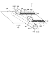
- FIG. 1 is a perspective view which shows roughly an example of the shaping process for manufacture of the film with a knurled structure of this invention, and the film with the knurled structure of this invention manufactured by it.
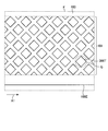
- FIG. 2 is a top view schematically showing an enlarged region indicated by a dotted line F of the knurl-structured film 100 shown in FIG.
- FIG. 3 is a longitudinal sectional view schematically showing an enlarged relationship between the back roll 110, the film, and the knurl 120 of the shaping apparatus shown in FIG. 1.
- FIG. 4 is a top view schematically showing an enlarged region indicated by a dotted line G of the knurl-structured film 100 shown in FIG.
- FIG. 1 is a perspective view which shows roughly an example of the shaping process for manufacture of the film with a knurled structure of this invention, and the film with the knurled structure of this invention manufactured by it.
- FIG. 2 is a top view schematically showing an enlarged region indicated by a
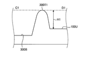
- FIG. 5 is a cross-sectional view of the knurl structure unit shown in FIG. 4 at a certain point in the top portion 300T.
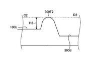
- FIG. 6 is a cross-sectional view of the knurl structural unit shown in FIG. 4 at another point in the top portion 300T.
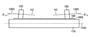
- FIG. 7 is an elevation view schematically showing an example of an aspect of inclination of the rotation axis of the knurl.
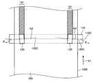
- FIG. 8 is a top view schematically showing another example of the inclination of the rotation axis of the knurl.
- the direction of the component of the member for carrying out the method of the present invention “parallel” may include an error within a range that does not significantly impair the effects of the present invention (for example, ⁇ 5 °).
- the “long” film means a film having a length of 5 times or more, preferably 10 times or more, more specifically in a roll shape. It has a length enough to be wound up and stored or transported.
- the upper limit of the ratio of the length with respect to the width of a film is not specifically limited, For example, it can be 100,000 times or less.
- the film with a knurled structure of the present invention is a long film with a knurled structure, and the film with a knurled structure includes a knurled region provided at an end in the width direction.
- the method of manufacturing the film with a knurled structure of the present invention is not particularly limited, an example of a preferable manufacturing method includes a specific manufacturing method including a shaping step using a back roll and a knurl. Below, the said manufacturing method is demonstrated as a manufacturing method of this invention.
- a rotating back roll is brought into contact with one surface of a long film to be conveyed to support the film, and a rotating knurl is pressed against the other surface.
- a knurl structure is formed in the width direction edge part of a film.
- a film for producing a film with a knurled structure of the present invention which is in a state before the knurled structure is formed, may be referred to as a “film before processing” for distinction.
- the film before processing and the film with a knurled structure may be collectively referred to simply as “film”.
- FIG. 1 is a perspective view schematically showing an example of a shaping process for producing a film with a knurled structure of the present invention and a film with a knurled structure of the present invention produced thereby.
- the shaping apparatus 1 includes a back roll 110 and a pair of knurls 120.
- the knurl is arranged on the upper side of the film conveyance path and the back roll is arranged on the lower side, but the shaping process is not limited to this, for example, the knurl is arranged on the lower side and the back roll is arranged on the upper side. It is also possible to arrange.
- the back roll 110 has a cylindrical peripheral surface, and the peripheral surface is a smooth surface at a portion where the knurl 120 is pressed.
- the peripheral surface other than the portion where the knurl 120 is pressed may be smooth or non-smooth.
- the back roll 110 is supported by an arbitrary support device (not shown) so as to be rotatable about its axis 110C.
- the back roll 110 is further provided so as to be driven in the direction of the arrow R1 by an arbitrary driving device.
- the driving device may be a device that applies a driving force via the shaft 110C.
- the back roll is not limited to such a drive.
- the back roll 110 may not be accompanied by a drive device, but may be simply supported so as to be able to rotate and rotate following the film.
- the knurling is a roll having a concavo-convex structure on its peripheral surface.
- the knurl 120 is supported by an arbitrary support device (not shown) so as to be rotatable about its axis 120 ⁇ / b> C and biased toward the back roll 110. Thereby, the knurl 120 can be pressed against the back roll 110.
- the knurl 120 is further provided so as to be driven in the direction of the arrow R2 by an arbitrary driving device.
- the shaft 120 ⁇ / b> C of the knurl 120 is arranged in an angular relationship that is parallel to or nearly parallel to the shaft 110 ⁇ / b> C of the back roll 110.
- the position where the knurl 120 is provided is adjusted so that the circumferential surface of the knurl 120 abuts the film at the end in the film width direction in the film conveyance path.
- the shaping apparatus 1 can further optionally include a component (not shown) for transporting the film and a component (not shown) for performing an optional step such as a feedback step.
- the long unprocessed film 10 introduced into the shaping apparatus 1 is conveyed in the direction of the arrow A1, guided between the back roll 110 and the knurl 120, and sandwiched between them.
- the film transport direction is the horizontal direction.
- the shaping step is not limited to this, and the film conveyance direction may be any direction.
- the back roll 110 is driven to rotate in the direction of arrow R1, and the knurl 120 is driven to rotate in the direction of arrow R2. Further, the knurl 120 is pressed against the back roll 110.
- the rotating back roll 110 is brought into contact with the lower surface of the unprocessed film 10 to be conveyed to support the unprocessed film 10, and the rotating knurl is pressed against the upper surface of the unprocessed film 10. Can be made.
- a knurl structure can be formed at the end in the width direction of the unprocessed film.
- the width of the upper surface of the pre-treatment film 10 is transferred to the pre-treatment film 10 that has passed between the back roll 110 and the knurl 120 by transferring the concavo-convex structure on the peripheral surface of the knurl 120.
- a band-shaped nar region 101 in which a large number of nar structure units are formed is formed at both ends in the direction, whereby the nar structure-attached film 100 is manufactured.
- the end portion in the width direction of the film may be a region provided in contact with the edge 100E of the film, but the inner side of the edge 100E in the width direction of the film as in the region 101 in the example of FIG. Alternatively, it may be a region in the vicinity of the edge 100E set apart from the edge 100E.
- the knurled region has a plurality of knurled structural units, and each knurled structural unit has one concave portion and a top portion that is formed around the concave portion and is continuous in a bowl shape.
- each knurled structural unit has one concave portion and a top portion that is formed around the concave portion and is continuous in a bowl shape.
- FIG. 2 is a top view schematically showing an enlarged region indicated by a dotted line F of the knurl-structured film 100 obtained by the shaping step shown in FIG.
- FIG. 3 is a longitudinal sectional view schematically showing an enlarged relationship between the back roll 110, the film, and the knurl 120 of the shaping apparatus shown in FIG.
- a plurality of knurl structure units formed by transferring the concavo-convex structure on the peripheral surface of the knurl 120 are formed.
- the arrangement of nar structural units is illustrated by indicating the position of the top portion 300T.
- the knurl structure unit 300 is formed by the protrusion 121 on the circumferential surface of the knurled 120 being pressed against the unprocessed film 10 and, as a result, the shape of the tip of the protrusion 121 is transferred. It is.
- the knurl structure unit 300 includes a concave portion 300B corresponding to the shape of the protrusion 121 and a top portion 300T formed around the concave portion 300B.
- the convex structure including the top part 300T is a bowl-like structure formed by the protrusion 121 being pressed against the pre-processing film 10 and a material such as resin constituting the film being ejected around the concave part 300B. . Therefore, the top portion 300T usually extends in a closed curve shape that surrounds the entire circumference of the recess portion 300B.
- each apex 300T of the nar structure unit has a shape extending to a rhombus shape as shown in FIG.
- the recess 300B of the nar structure unit 300 of the nar structure film 100 that is conveyed horizontally is at a lower level than the upper surface 100U of the film without the nar structure unit 300, while the top portion 300T The level is higher than the upper surface 100U.
- the lower surface 100D of the knurl-structured film 100 is in a substantially flat state without a substantial uneven structure.
- the thickness of the film 100 with the nar structure is thinner in the region where the recess 300B is formed than in the region without the nar structure unit 300, and thicker in the region near the top portion 300T than the region without the nar structure unit 300. ing.
- FIG. 4 is a top view schematically showing an enlarged region indicated by a dotted line G of the knurl-structured film 100 shown in FIG.
- the top part 300T of one nar structural unit is shown enlarged.
- 5 and 6 are cross-sectional views at certain points in the top portion 300T of the nar structure unit shown in FIG.
- FIG. 5 is a cross-sectional view taken along a line C1-D1 including a certain point 300T1 of the top portion 300T extending in a rhombus and cut in the vicinity of the top portion at a plane perpendicular to the film with a knurl structure 100.
- FIG. 6 is a cross-sectional view of the vicinity of the top portion taken along a line C2-D2 including another certain point 300T2 in the top portion 300T and perpendicular to the film 100 with the knurled structure.
- the height of the top of the nar structural unit is indicated by the difference in level between the top and the film surface in the region having no nar structural unit.
- the height H1 of the top is a difference in level between the top 300T1 and the surface 100U on the upper side of the film in the region not having the nar structure unit 300
- the height of the top portion 300T which is continuous in the shape of a bowl in each nar structure unit can be set to a non-uniform height.
- a microscope for example, Keyence Corporation ultra deep microscope VK-9500
- the height Hmin at the low position Tmin can be measured.
- the average values AvHmax and AvHmin can be obtained by obtaining Hmax and Hmin in a predetermined number or more (for example, 10 or more) of nar structure units.
- such AvHmax and AvHmin satisfy the above formula (1).
- the upper limit of the number of measurement is not particularly limited, but may be 100 or less, for example.
- the upper limit of the number of measurements can be the same in the following other measurements.
- the value of AvHmax / AvHmin is more than 1.05, preferably 1.10 or more, more preferably 1.50 or more.
- the value of AvHmax / AvHmin is 30 or less, preferably 20 or less, more preferably 10 or less. According to the finding of the present inventor, the value of AvHmax / AvHmin is within such a range, so that the knurling of the knurled structure can be reduced.
- AvHmax and AvHmin are not particularly limited, and may be an appropriate value for obtaining a desired effect.
- AvHmax is preferably 5 ⁇ m or more, more preferably 10 ⁇ m or more, while preferably 50 ⁇ m or less, more preferably 20 ⁇ m or less.
- AvHmin is preferably 1 ⁇ m or more, more preferably 3 ⁇ m or more, while preferably 30 ⁇ m or less, more preferably 10 ⁇ m or less.
- the top height deviation there is no particular limitation on the form of the top height deviation, and various forms can be used.
- the distribution of the position of the top portion Tmax that gives the maximum height Hmax may be unevenly distributed in the longitudinal direction of the film with a knurled structure. More specifically, the unevenness of the height of the top can be unevenly distributed in the longitudinal direction of the knurled film.
- the bias caused by Vr> Vb can be a bias that is higher on the downstream side than on the upstream side of the nar structure unit.
- the presence or absence of uneven distribution of the position of Tmax in the longitudinal direction is parallel to the width direction of the film with a nar structure in each of a predetermined number or more (for example, 10 or more) of nar structure units, and the top of the nar structure unit. If the top is divided into an upstream side and a downstream side with a line that bisects the equal length into two, it is determined whether the highest position Tmax of the top part exists on the downstream side or the upstream side, It can be determined that there is a deviation in the height of the top when Tmax is unevenly distributed on either the downstream side or the upstream side in a nar structure unit of a ratio (for example, 70%) or more.
- a ratio for example, 70%
- a line D-TD that is parallel to the width direction of the nar structure film 100 and bisects the top part 300T of the nar structure unit into equal lengths is defined as a boundary.
- the position of Tmax is unevenly distributed on either the upstream side (left side in the drawing of FIG. 4) or the downstream side (right side in the drawing of FIG. 4). sell. More specifically, when Vr> Vb, a portion having a high top can be unevenly distributed on the downstream side from the upstream side.
- the position of Tmax is unevenly distributed in the longitudinal direction of the film with a knurled structure, it is preferable because a smooth film with a knurled structure can be produced without excessively deforming the film.
- the position of Tmax is unevenly distributed on the downstream side because the production of a film with a knurled structure can be performed more smoothly.
- the distribution of the position of the top portion Tmax that gives the maximum height Hmax can be a distribution that is unevenly distributed in the width direction of the film with a knurled structure. That is, it is possible to provide a top height deviation that is higher on the other side than the inner side and the outer side of the nar structure unit.
- the inner side is the side close to the center in the film width direction
- the outer side is the side far from the center in the film width direction.
- the presence or absence of uneven distribution of the position of Tmax in the width direction is parallel to the longitudinal direction of the film with a nar structure in each of a predetermined number or more (for example, 10 or more) of nar structure units, and the top of the nar structure unit.
- a line D-MD which is parallel to the longitudinal direction of the nar structure film 100 and bisects the top portion 300T of the nar structure unit into equal lengths is defined as a boundary.
- the position of Tmax may be unevenly distributed on the other side.
- the uneven distribution of the top height in the width direction of the film with a knurl structure can be provided by arranging the knurls such that the direction of the rotation axis of the knurl is inclined with respect to the width direction of the film.
- the position of Tmax is unevenly distributed in the width direction of the film with a knurled structure, it is preferable because the film with a knurled structure can be manufactured smoothly while the film is stably conveyed. In particular, it is preferable that the position of Tmax is unevenly distributed on the inner side because a film with a knurled structure can be manufactured more smoothly.
- each nar structure unit is not particularly limited and may be a desired size.
- the average of the length in the film longitudinal direction and the length in the width direction is preferably 50 ⁇ m or more, more preferably 100 ⁇ m or more, and preferably 20000 ⁇ m or less, more preferably 10,000 ⁇ m or less.
- the knurling peripheral speed Vr is higher than the back roll peripheral speed Vb (that is, Vr> Vb). It is preferable to adjust the speed. Vr and Vb more preferably satisfy the following formula (2). 1 ⁇ Vr / Vb ⁇ 1.15 Formula (2)
- Vr and Vb are adjusted to be as equal as possible.
- Vr and Vb are adjusted to be as equal as possible.
- Vr and Vb are adjusted to be as equal as possible.
- Vr and Vb are adjusted to be as equal as possible.
- Vr and Vb are adjusted to be as equal as possible.
- a bias is formed in which the position of Tmax is unevenly distributed from the upstream side to the downstream side of the knurled structure unit, and a knurled film satisfying the requirements of the formula (1) and the like is manufactured. Can do. Moreover, by making Vr larger than Vb, a sufficient deviation can be obtained and smooth conveyance and shaping can be achieved. Also, by setting Vr / Vb to less than 1.15, high molding accuracy can be maintained.
- the Vr / Vb is preferably 1.01 ⁇ Vr / Vb ⁇ 1.12, and more preferably 1.02 ⁇ Vr / Vb ⁇ 1.10.
- the inclination of the rotation axis of the knurl can be adjusted. Such adjustment of the inclination can be performed so that the direction of the rotation axis of the knurl is inclined with respect to the width direction of the film. By performing such adjustment, it is possible to manufacture a film with a knurled structure that forms a bias in which the position of Tmax is unevenly distributed inside or outside the knurled structural unit and satisfies the requirements of the above formula (1) and the like.
- FIG. 7 is an elevation view schematically showing an example of an aspect of inclination of the rotation axis of the knurl.
- FIG. 7 the state which observed the back roll 110, the film 100 with a knurl structure, and the knurl 120 from the film conveyance direction is shown. 7, the rotation shaft 120C of the pair of knurling 120, to the film width direction parallel to the direction (direction indicated by a dotted line HZ), an angle theta 12, perpendicular to the vertical direction (the film surface In the right direction).
- the rotation axis of the knurl When the rotation axis of the knurl is arranged so as to be inclined with respect to the width direction of the film, the inclination is such that the rotation axis is close to the film on the inner side in the width direction of the film as in the example of FIG. It is preferable that the rotation axis is inclined in a direction away from the film on the outer side in the direction. By setting the inclination in such a direction, it is possible to provide a deviation in the height of the top of the knurled unit, and in addition, the conveyance of the film can be stabilized and a smooth shaping process can be performed.
- a preferable range of ⁇ 12 is 0 to 5 °, and more preferably 0 to 3 °.
- the inclination of the rotation shaft 120C shown in FIG. 7 is an inclination in which the rotation axis is inclined in the vertical direction, but instead of or in addition to this, the rotation axis in the horizontal direction (the direction horizontal to the film surface). An inclination may be provided.
- FIG. 8 is a top view schematically showing another example of the inclination of the rotation axis of the knurl.
- the rotation shaft 120 ⁇ / b> C of the pair of knurls 120 is inclined in the horizontal direction at an angle ⁇ 13 with respect to a direction parallel to the film width direction (direction indicated by a dotted line HZ).
- the rotation axis of the knurling is arranged so as to be inclined with respect to the film width direction, the inclination is similar to the example of FIG. It is preferable that the rotation axis is inclined in a direction away from the upstream in the direction inner side. By setting the inclination in such a direction, it is possible to provide a deviation in the height of the top of the knurled unit, and in addition, the conveyance of the film can be stabilized and a smooth shaping process can be performed.
- a preferable range of ⁇ 13 is 0 to 5 °, and more preferably 0 to 3 °.
- the film transport speed Vt in the transport process is preferably 20 m / min or more, more preferably 50 m / min or more.
- the upper limit of the conveyance speed is not particularly limited, but may be 200 m / min or less, for example. By setting the transport speed to be equal to or higher than the lower limit, a knurl structure with less knurl return can be easily formed.
- the film transport speed Vt in the transport process is preferably equal to or less than the peripheral speed Vb of the back roll to maintain smooth transport and high molding accuracy. Specifically, it is preferable that 0.95 ⁇ Vt / Vb ⁇ 1.05.
- the speed ratio Vt / Vb is more preferably 0.99 ⁇ Vt / Vb ⁇ 1.01.
- the back roll used in the conveying step preferably has a Young's modulus of the peripheral surface larger than the Young's modulus of the film. More preferably, the Young's modulus of the peripheral surface of the back roll is 1.5 times or more of the Young's modulus of the film. Even more preferably, the Young's modulus of the peripheral surface of the back roll is 1.5 to 10 times the Young's modulus of the film.
- a Young's modulus back roll a film 100 with a knurled structure having a knurled structure on the knurled side as shown in the example of FIG. It can manufacture smoothly without accompanying.
- the Young's modulus can be measured by a commercially available micro hardness meter, for example, a micro hardness meter PICODETOR HM500 manufactured by Fisher, based on ASTM D638.
- the back roll may or may not be provided with a driving force from the driving device.
- the driving force Fr applied to the knurl peripheral surface and the driving force Fb applied to the back roll peripheral surface are: It is preferable to satisfy the relationship of Fr ⁇ Fb.
- Fr and Fb may more preferably have a relationship of 1 ⁇ Fr / Fb ⁇ 2.
- the temperature at which the shaping step is performed is not particularly limited, and may be, for example, a room temperature environment. However, it is preferable that the knurl is heated by an appropriate heating device to be brought into contact with the pre-treatment film at a constant temperature suitable for the formation of the knurled structure.
- the preferable knurling temperature can be set to a preferable temperature relative to the glass transition temperature Tg of the film. Specifically, it is preferably (Tg + 10) ° C. or higher, more preferably (Tg + 20) ° C. or higher, and preferably (Tg + 200) ° C. or lower, more preferably (Tg + 150) ° C. or lower.
- the film with a knurled structure of the present invention may have a knurled film region over its entire length, but the knurled region may be provided intermittently and may not have a knurled region in a part of the longitudinal direction. .
- a continuous process may be performed over the entire length of the long unprocessed film, but the shaping process is limited to such a continuous process.
- it may be an intermittent process in which the shaping process is not performed over a part.
- the operation when the shaping step is not performed is preferably to release the pressure contact by separating the knurling from the film while maintaining the support of the back roll.
- the shaping process for producing the film with a knurled structure of the present invention is not limited to the one using the shaping apparatus including the back roll and the knurling, such as the shaping apparatus 1 exemplified above, and the requirements of the present invention It can be the process of the arbitrary aspect which can form the nar structure which satisfy
- the film before processing is irradiated with a laser beam to process its widthwise end, and the intensity of the laser beam, the irradiation angle, and the scanning pattern are appropriately adjusted to form a knurled structure that satisfies the requirements of the present invention. May be.
- an optional step can be performed in addition to the shaping step described above.
- a measurement process for measuring the height of the knurled structure formed in the shaping process, and feedback for feedback control of the height of the knurled structure formed in the shaping process based on the height measured in the measuring process may further include a process.
- the specific method of measurement in the measurement process is not particularly limited, and a known method capable of continuously measuring the height of a large number of nar structure units with a knurl structure to be conveyed can be appropriately selected and adopted.
- a measuring instrument for performing such a measurement a known device for measuring the dimensions of the observed object to be observed is selected as appropriate by irradiating the object to be measured with laser and receiving and analyzing the reflected light. sell.
- a CCD laser displacement meter such as a product name “LK series” manufactured by Keyence Corporation can be used.
- the height of the knurl structure can be controlled by appropriately changing the conditions of the shaping process.
- the pressure of the knurling pressure, the peripheral speed ratio of the knurling and the back roll, the angle of inclination of the knurling shaft, the torque of the knurling, the torque of the back roll This can be done by appropriately changing one or more of the conditions such as the knurling temperature.
- the film with a knurled structure and the method for producing the same of the present invention are not limited to the examples specifically described above, and may be variously modified.
- the knurl is arranged on the upper side of the film to be transported horizontally and the back roll is arranged on the lower side, but the present invention is not limited to this, for example, the knurl is arranged on the lower side and the upper side is arranged. It is also possible to arrange a back roll.
- the knurled structure is usually provided at both ends in the width direction of the film with the knurled structure, but the present invention is not limited to this.
- the knurled structure has one end in the film width direction. You may provide only.
- the knurl structure may be provided in other areas such as the center in the film width direction.
- the dimension of the film before a process used for manufacture of the film with a knurl structure of this invention is not specifically limited, It can be set as the arbitrary dimension desired in a film with a nar structure.
- the thickness of the pre-treatment film is preferably 10 ⁇ m or more, more preferably 20 ⁇ m or more, while preferably 200 ⁇ m or less, more preferably 150 ⁇ m or less. Since the film having such a thickness range is particularly easily deformed and easily returns to the knurling, the effect can be advantageously obtained by providing the shape with the knurled film of the present invention.
- the material of the film before a process used for manufacture of the film with a knurled structure of the present invention is not particularly limited, and various films can be used.
- the film may be a stretched film or an unstretched film.
- the pre-treatment film When using a film with a knurled structure as an optical film, it is usually preferable that the pre-treatment film has high transparency from the viewpoint of exhibiting a function as an optical member.
- the total light transmittance of the pre-treatment film is preferably 80% or more, and more preferably 90% or more.
- the total light transmittance is an average value obtained by measuring five points using “turbidimeter NDH-2000” manufactured by Nippon Denshoku Industries Co., Ltd. according to JIS K7105.
- the film before treatment has a small haze.
- the haze of the pre-treatment film is preferably 5% or less, more preferably 3% or less, and particularly preferably 2% or less.
- the pre-treatment film is usually a resin film containing various polymers.
- polymers include hydrocarbon polymers, (meth) acrylic polymers and polyesters.
- the pre-treatment film preferably contains a hydrocarbon polymer.
- the “including hydrocarbon polymer” film includes a film including one or more resin layers including a hydrocarbon polymer, one or more resin layers including a hydrocarbon polymer, and any other layer. Both films comprising one or more layers are included.
- the hydrocarbon polymer refers to a polymer in which at least a part of the repeating unit of the polymer is a hydrocarbon group.
- the proportion of the hydrocarbon group which is a repeating unit in the hydrocarbon polymer can be appropriately selected according to the purpose of use, but is preferably 55% by weight or more, more preferably 70% by weight or more, and particularly preferably 90% by weight. That's it.
- an alicyclic structure-containing polymer is preferable.
- a resin film containing an alicyclic structure-containing polymer has good characteristics as an optical film, but it is easy to cause a knurl return when a knurl structure is added to form a film roll. The effect can be advantageously obtained by providing the shape of the film.
- An alicyclic structure-containing polymer is a polymer having an alicyclic structure in the repeating unit of the polymer, a polymer having an alicyclic structure in the main chain, and an alicyclic structure in the side chain. Any of the polymers it has may be used. Among these, a polymer containing an alicyclic structure in the main chain is preferable from the viewpoint of mechanical strength, heat resistance, and the like.
- Examples of the alicyclic structure include a saturated alicyclic hydrocarbon (cycloalkane) structure and an unsaturated alicyclic hydrocarbon (cycloalkene, cycloalkyne) structure.
- a saturated alicyclic hydrocarbon cycloalkane
- an unsaturated alicyclic hydrocarbon cycloalkene, cycloalkyne
- a cycloalkane structure and a cycloalkene structure are preferable, and a cycloalkane structure is particularly preferable.
- the number of carbon atoms constituting the alicyclic structure is preferably 4 or more, more preferably 5 or more, preferably 30 or less, more preferably 20 or less, particularly preferably per alicyclic structure. Is in the range of 15 or less, the mechanical strength, heat resistance, and film formability are highly balanced, which is preferable.
- the proportion of the repeating unit having an alicyclic structure in the alicyclic structure-containing polymer can be appropriately selected according to the purpose of use, but is preferably 55% by weight or more, more preferably 70% by weight or more, particularly preferably. 90% by weight or more.
- the ratio of the repeating unit having an alicyclic structure in the alicyclic structure-containing polymer is in this range, it is preferable from the viewpoint of transparency and heat resistance of the film.
- alicyclic structure-containing polymers examples include norbornene polymers, monocyclic olefin polymers, cyclic conjugated diene polymers, vinyl alicyclic hydrocarbon polymers, and hydrides thereof. Can be mentioned. Among these, norbornene-based polymers can be suitably used because of their good transparency and moldability.
- Examples of the norbornene-based polymer include a ring-opening polymer of a monomer having a norbornene structure, a ring-opening copolymer of a monomer having a norbornene structure and any other monomer, or hydrogen thereof.
- a ring-opening (co) polymer hydride of a monomer having a norbornene structure is particularly suitable from the viewpoints of transparency, moldability, heat resistance, low hygroscopicity, dimensional stability, lightness, and the like. Can be used.
- “(Co) polymer” means a polymer and a copolymer.
- Examples of the monomer having a norbornene structure include bicyclo [2.2.1] hept-2-ene (common name: norbornene), tricyclo [4.3.0.1 2,5 ] deca-3,7. -Diene (common name: dicyclopentadiene), 7,8-benzotricyclo [4.3.0.1 2,5 ] dec-3-ene (common name: methanotetrahydrofluorene), tetracyclo [4.4. 0.1 2,5 . 1 7,10 ] dodec-3-ene (common name: tetracyclododecene), and derivatives of these compounds (for example, those having a substituent in the ring).
- examples of the substituent include an alkyl group, an alkylene group, and a polar group. Moreover, these substituents may be the same or different, and a plurality thereof may be bonded to the ring.
- One type of monomer having a norbornene structure may be used alone, or two or more types may be used in combination at any ratio.
- Examples of the polar group include heteroatoms or atomic groups having heteroatoms.
- Examples of the hetero atom include an oxygen atom, a nitrogen atom, a sulfur atom, a silicon atom, and a halogen atom.
- Specific examples of the polar group include a carboxyl group, a carbonyloxycarbonyl group, an epoxy group, a hydroxyl group, an oxy group, an ester group, a silanol group, a silyl group, an amino group, a nitrile group, and a sulfonic acid group.
- optional monomers capable of ring-opening copolymerization with a monomer having a norbornene structure include, for example, monocyclic olefins such as cyclohexene, cycloheptene, and cyclooctene and derivatives thereof; and cyclic conjugates such as cyclohexadiene and cycloheptadiene. Dienes and derivatives thereof; and the like.
- the optional monomer capable of ring-opening copolymerization with a monomer having a norbornene structure one type may be used alone, or two or more types may be used in combination at any ratio.
- a ring-opening polymer of a monomer having a norbornene structure, and a ring-opening copolymer of any monomer copolymerizable with a monomer having a norbornene structure are, for example, a known ring-opening monomer. It can be obtained by polymerization or copolymerization in the presence of a polymerization catalyst.
- optional monomers that can be addition-copolymerized with a monomer having a norbornene structure include, for example, ⁇ -olefins having 2 to 20 carbon atoms such as ethylene, propylene, and 1-butene, and derivatives thereof; cyclobutene, cyclopentene, And cycloolefins such as cyclohexene and derivatives thereof; non-conjugated dienes such as 1,4-hexadiene, 4-methyl-1,4-hexadiene, 5-methyl-1,4-hexadiene; and the like.
- ⁇ -olefin is preferable, and ethylene is more preferable.
- Any monomer that can be addition copolymerized with a monomer having a norbornene structure may be used alone, or two or more monomers may be used in combination at any ratio.
- An addition copolymer of a monomer having a norbornene structure and an addition copolymer of any monomer that can be copolymerized with a monomer having a norbornene structure include, for example, a monomer of a known addition polymerization catalyst. It can be obtained by polymerization or copolymerization in the presence.
- Examples of monocyclic olefin polymers include addition polymers of cyclic olefin monomers having a single ring such as cyclohexene, cycloheptene, and cyclooctene.
- cyclic conjugated diene polymer examples include polymers obtained by cyclization reaction of addition polymers of conjugated diene monomers such as 1,3-butadiene, isoprene and chloroprene; cyclic conjugated such as cyclopentadiene and cyclohexadiene. And 1,2- or 1,4-addition polymers of diene monomers; and their hydrides.
- vinyl alicyclic hydrocarbon polymers include polymers of vinyl alicyclic hydrocarbon monomers such as vinylcyclohexene and vinylcyclohexane and their hydrides; vinyl aromatic hydrocarbons such as styrene and ⁇ -methylstyrene. Hydrogenated product obtained by hydrogenating an aromatic ring part contained in a polymer obtained by polymerizing monomers; a polymer of vinyl alicyclic hydrocarbon monomers, or vinyl aromatic hydrocarbon monomers and these vinyl aromatic hydrocarbons
- An aromatic ring hydride of a copolymer such as a random copolymer or a block copolymer with any monomer copolymerizable with the monomer can be used.
- the block copolymer include a diblock copolymer, a triblock copolymer or a multi-block copolymer having more than that, a gradient block copolymer, and the like.
- the molecular weight of the hydrocarbon polymer is appropriately selected according to the purpose of use, but gel permeation chromatography using cyclohexane as a solvent (however, if the sample does not dissolve in cyclohexane, toluene may be used).
- the polyisoprene or polystyrene-equivalent weight average molecular weight (Mw) measured in (1) is usually 10,000 or more, preferably 15,000 or more, more preferably 20,000 or more, and usually 100,000 or less, preferably 80,000. 000 or less, more preferably 50,000 or less. When the weight average molecular weight is in such a range, the mechanical strength and molding processability of the film are highly balanced and suitable.
- the molecular weight distribution (weight average molecular weight (Mw) / number average molecular weight (Mn)) of the hydrocarbon polymer is usually 1.2 or more, preferably 1.5 or more, more preferably 1.8 or more, usually 3.5. Hereinafter, it is preferably 3.0 or less, more preferably 2.7 or less.
- Mw weight average molecular weight
- Mn number average molecular weight
- the glass transition temperature of the hydrocarbon polymer can be appropriately selected according to the purpose of use, but is preferably 80 ° C. or higher, more preferably 100 ° C. or higher, preferably 200 ° C. or lower, more preferably 180 ° C. or lower. .
- the glass transition temperature is lower than 80 ° C., durability at high temperatures may be deteriorated.
- the glass transition temperature is higher than 200 ° C., durability is improved, but normal stretching may be difficult.
- the resin layer constituting the film may contain other optional components in addition to the polymer such as the alicyclic structure-containing polymer as long as the effects of the present invention are not significantly impaired.
- optional components include colorants such as pigments and dyes; fluorescent brighteners; dispersants; thermal stabilizers; light stabilizers; ultraviolet absorbers; antistatic agents; antioxidants; Is mentioned.
- an arbitrary component may be used individually by 1 type, and may be used combining two or more types by arbitrary ratios.
- the resin layer constituting the film preferably contains about 50% to 100% or about 70% to 100% of a polymer such as an alicyclic structure-containing polymer.
- the pre-treatment film used in the production of the film with a knurled structure of the present invention can be obtained by molding a resin by a known film molding method.
- the film forming method include a cast forming method, an extrusion forming method, and an inflation forming method.
- the melt extrusion method that does not use a solvent can reduce the amount of residual volatile components efficiently, and is preferable from the viewpoints of the global environment and work environment, and excellent manufacturing efficiency.
- Examples of the melt extrusion method include an inflation method using a die, and a method using a T die is preferable in terms of excellent productivity and thickness accuracy.
- the obtained resin layer can be used as it is as a film for production of the film with a knurl structure of the present invention.
- an arbitrary layer such as an easy-sliding layer or an antistatic layer may be arbitrarily formed on the surface of the obtained resin layer, and this may be used as a film for production.
- Example A1 (A1-1. Preparation of film before treatment) A pellet of an alicyclic structure-containing polymer resin (“ZEONOR1430” manufactured by Nippon Zeon Co., Ltd .; glass transition temperature: 135 ° C.) was dried at 70 ° C. for 2 hours using a hot air dryer in which air was circulated. The dried pellets were supplied to a T-die type film melt extrusion machine having a resin melt kneader equipped with a 65 mm diameter screw. Using this molding machine, a pre-treatment film having a thickness of 50 ⁇ m, a width of 1200 mm, and a length of 4000 m was produced under the molding conditions of a molten resin temperature of 270 ° C. and a T-die width of 1500 mm. The Young's modulus of this film was 2.2 GPa.
- the shaping process was performed using the shaping apparatus 1 schematically shown in FIGS. 1 and 3.
- the unprocessed film 10 produced in (A1-1) was conveyed in the direction of arrow A1 in the shaping apparatus 1.
- the conveyance speed was 50 m / min.
- the knurling 120 is pressed against both ends in the width direction of the upper surface, thereby forming the shape.
- the process was carried out.
- a back roll 110 having a diameter of 150 mm and a Young's modulus of the peripheral surface of 207 GPa was used.
- the back roll 110 was rotated in the arrow R1 direction at a peripheral speed of 50 m / min.
- the knurl 120 one having a diameter of 110 mm and having a concavo-convex structure including a protrusion 121 as shown in FIG.
- the temperature of the knurl 120 was 250 ° C., and the pressure of the pressure contact was 130N.
- the knurl 120 was rotated in the arrow R2 direction at a peripheral speed of 52 m / min. Therefore, the peripheral speed ratio Vr / Vb was 1.04.
- the vertical inclination angle ( ⁇ 12 in FIG. 7) of the shaft 120C of the knurled 120 was 1 °.
- nar structure unit 300 In the nar area 101 of the obtained nar structure-attached film 100, a large number of nar structure units 300 having apexes 300T extending in a rhombus shape were formed.
- the nar structure unit 300 is regularly arranged in the nar region 101 in the manner shown in FIG.
- the length in the film longitudinal direction of each Narle structural unit 300 was 0.4 mm, and the length in the film width direction was 0.4 mm.
- the position of the top portion Tmax giving Hmax in each of the extracted ten knurl structures 300 was examined.
- 7 out of 10 knurl structures 300 If more than one is present on either the upstream side or the downstream side, it is evaluated as asymmetric in the longitudinal direction (there is uneven distribution in the longitudinal direction). Otherwise, it is symmetrical in the longitudinal direction (uneven distribution in the longitudinal direction). There was a).
- the film with a knurled structure 100 measured in (A1-3) was used as a wound film roll.
- the winding was performed in a state where a tension of 100 N / m was applied to a winding core having an outer radius of 172 mm.
- the obtained film roll was stored for 3 months in a constant temperature environment of 25 ° C.
- the film with a knurled structure was unwound from the film roll, and the height of the knurled top was measured by the same procedure as (A1-3).
- AvHmax before storage and the rate of change of AvHmax after storage were calculated and evaluated according to the following evaluation criteria.
- Example A2 In (A1-2), the knurling was not pressed, but instead a knurled structure was given by laser irradiation. Other than this change, a film with a knurled structure was produced and evaluated by the same operation as in Example A1.
- a CO 2 laser light irradiation apparatus MLZ9510 Keyence Co., Ltd., laser wavelength 10.6 ⁇ m
- the polar angle in the direction of laser irradiation was set to 5 ° with respect to the normal direction of the upper surface of the pre-treatment film 10.
- the azimuth in the direction of laser irradiation is an azimuth that forms an angle of 45 ° with the longitudinal direction and the width direction of the pre-processed film, and the irradiating device is positioned in the azimuth that is downstream and inner side of the irradiation position on the film. .
- a diamond-shaped nar structure unit was drawn and formed in the nar area 101 in large numbers.
- the drawn shapes and their arrangement were the same as the shape and arrangement of the top 300T in Example A1.
- Example A3 In (A1-2), the peripheral speed of the knurl 120 was changed to 54 m / min. Other than this change, a film with a knurled structure was produced and evaluated by the same operation as in Example A1.
- Example A4 In (A1-2), the peripheral speed of the knurl 120 was changed to 55 m / min. Other than this change, a film with a knurled structure was produced and evaluated by the same operation as in Example A1.
- Example A5 In (A1-2), the peripheral speed of the knurl 120 was changed to 57 m / min. Other than this change, a film with a knurled structure was produced and evaluated by the same operation as in Example A1.
- Example A6 In (A1-2), the peripheral speed of the knurl 120 was changed to 50 m / min. Other than this change, a film with a knurled structure was produced and evaluated by the same operation as in Example A1.
- Example A7 In (A1-2), the peripheral speed of the knurl 120 was changed to 54 m / min, and the angle of the vertical inclination of the shaft 120C of the knurl 120 ( ⁇ 12 in FIG. 7) was set to 0 °. Other than these changes, a film with a knurled structure was produced and evaluated by the same operation as in Example A1.
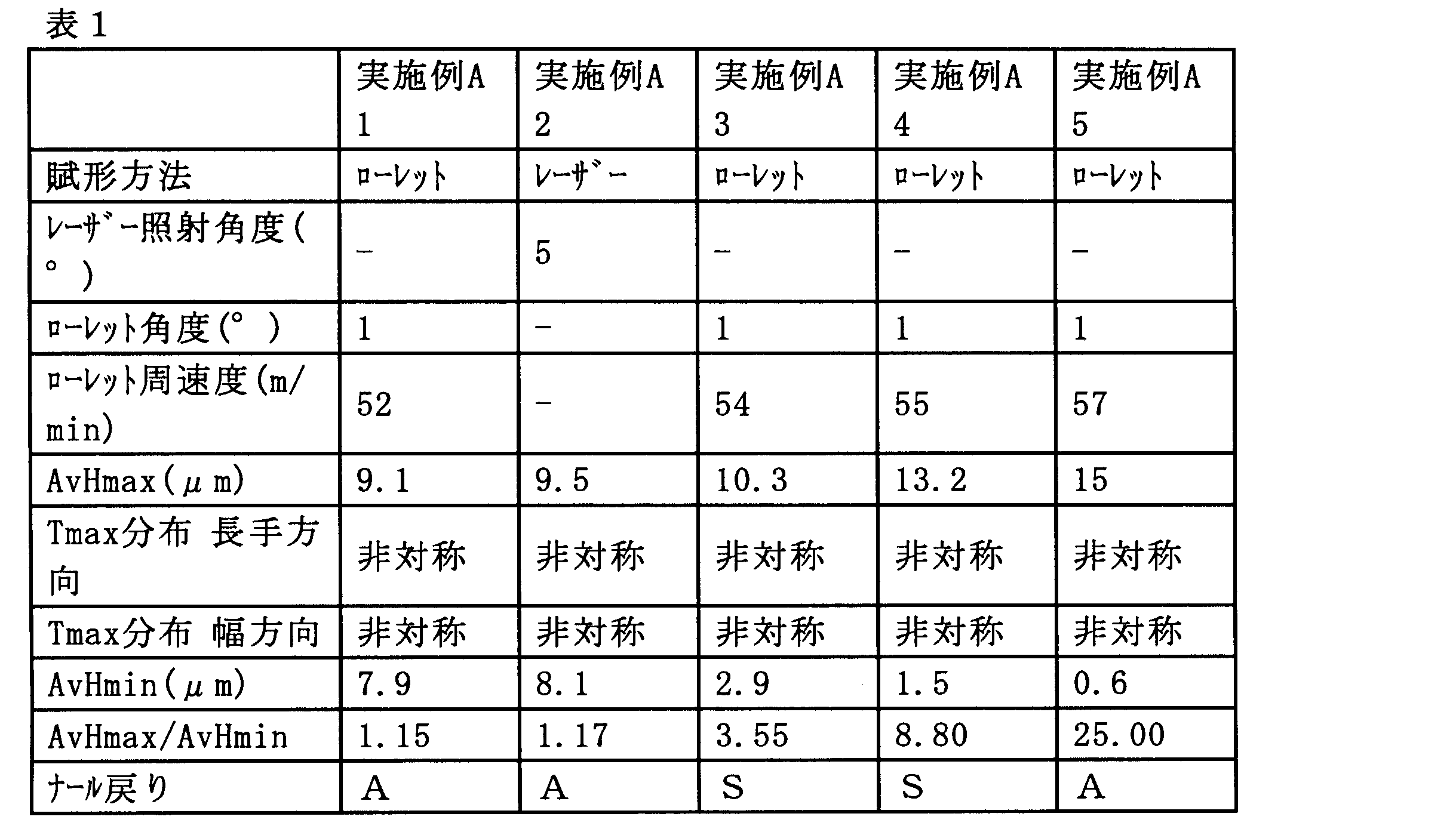
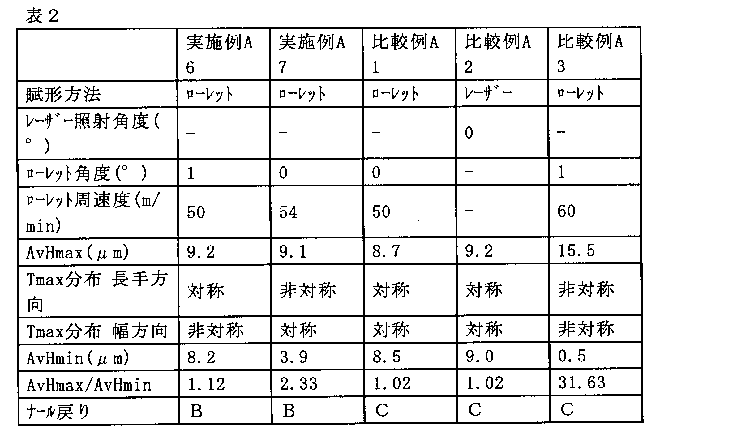
- Tables 1 and 2 show the evaluation results of Examples A1 to A7 and Comparative Examples A1 to A3.
- the knurl-structured film of the present invention has little knurl return.
- the film has a knurled structure with a change rate of less than 10%, particularly with a small knurled return.
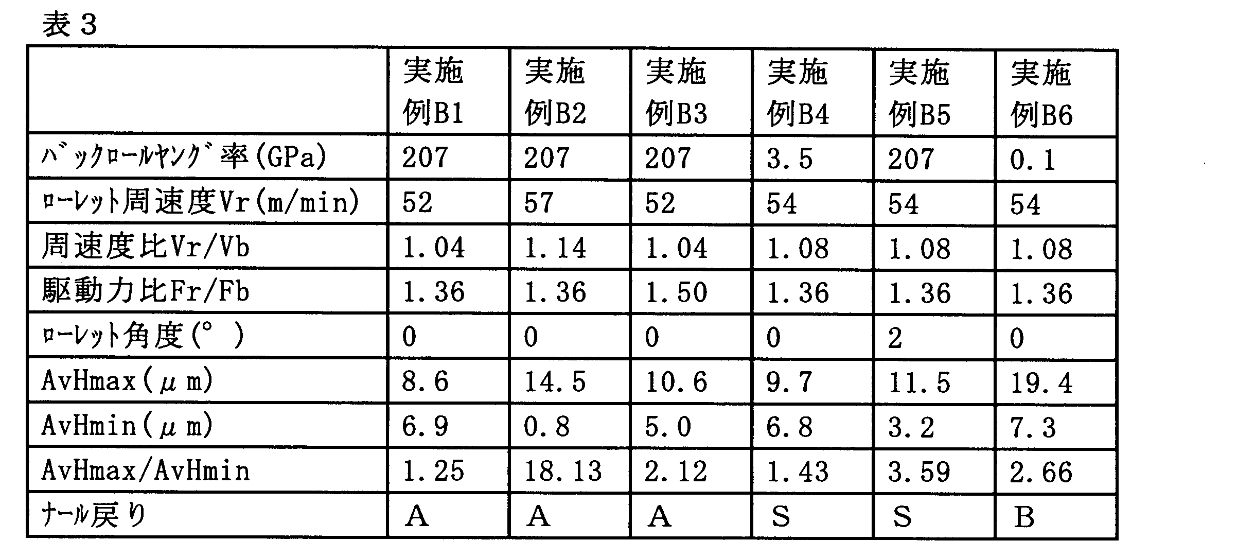
- Example B1 In (A1-2), the angle of vertical inclination ( ⁇ 12 in FIG. 7) of the axis 120C of the knurled 120 was changed to 0 °. Other than this change, a film with a knurled structure was produced and evaluated by the same operation as in Example A1.
- Example B2 In (A1-2), the peripheral speed of the knurl 120 was changed to 57 m / min. Further, the angle of vertical inclination of the shaft 120C of the knurl 120 ( ⁇ 12 in FIG. 7) was changed to 0 °. Other than these changes, a film with a knurled structure was produced and evaluated by the same operation as in Example A1.
- Example B3 In (A1-2), the torque of the knurl 120 was changed, and the torque ratio Tr / Tb was changed to 1.10. As a result, the driving force ratio Fr / Fb was set to 1.50. Further, the angle of vertical inclination of the shaft 120C of the knurl 120 ( ⁇ 12 in FIG. 7) was changed to 0 °. Other than these changes, a film with a knurled structure was produced and evaluated by the same operation as in Example A1.
- Example B4 In (A1-2), the back roll to be used was changed, and one having a diameter of 150 mm and a peripheral surface having a Young's modulus of 3.5 GPa was used. Further, the peripheral speed of the knurl 120 was changed to 54 m / min. Further, the angle of vertical inclination of the shaft 120C of the knurl 120 ( ⁇ 12 in FIG. 7) was changed to 0 °. Other than these changes, a film with a knurled structure was produced and evaluated by the same operation as in Example A1.
- Example B5 In (A1-2), the vertical inclination angle ( ⁇ 12 in FIG. 7) of the shaft 120C of the knurl 120 was changed to 2 °. Further, the peripheral speed of the knurl 120 was changed to 54 m / min. Other than these changes, a film with a knurled structure was produced and evaluated by the same operation as in Example A1.
- Example B6 In (A1-2), the back roll to be used was changed, and one having a diameter of 150 mm and a peripheral surface having a Young's modulus of 0.1 GPa was used. Further, the peripheral speed of the knurl 120 was changed to 54 m / min. Further, the angle of vertical inclination of the shaft 120C of the knurl 120 ( ⁇ 12 in FIG. 7) was changed to 0 °. Other than these changes, a film with a knurled structure was produced and evaluated by the same operation as in Example A1.
- Table 3 shows the evaluation results of Examples B1 to B6.
- shaping apparatus 10 pre-treatment film 100: film with nar structure 100D: lower surface 100E with nar structure film: film edge 100U: film upper surface 101 without nar structure unit: nar area 110: Back roll 110C: Back roll shaft 120: Knurled shaft 120C: Knurled shaft 121: Projection 300 on the circumferential surface of the knurl 300: Knurl structure unit 300B: Recess 300T: Knurl structure unit top portion 300T1: A point 300T2 at the top portion: Top portion A point H1: Top height H2: Top height
Landscapes
- Engineering & Computer Science (AREA)
- Mechanical Engineering (AREA)
- Shaping Of Tube Ends By Bending Or Straightening (AREA)
Abstract
Description
本発明者はまた、ナール構造の賦与を、バックロールとローレットとを組み合わせて用いた工程により行い、且つ当該工程における条件を特定のものとすることにより、上記製造を容易に行いうることを見出した。本発明は、かかる知見に基づき完成された。
すなわち、本発明によれば、下記〔A1〕~〔A3〕及び〔B1〕~〔B10〕が提供される。〔B1〕~〔B10〕の製造方法は、〔A1〕~〔A3〕のナール構造付きフィルムの製造に用いうる。
前記ナール構造付きフィルムは、その幅方向端部に設けられたナール領域を備え、
前記ナール領域は、複数のナール構造単位を有し、
それぞれの前記ナール構造単位は、1つの凹部と、前記凹部の周囲に形成された、畝状に連続した頂部を有し、
前記ナール構造単位は、以下の式(1)を満たす、ナール構造付きフィルム:
1.05<AvHmax/AvHmin≦30 (1)
但し式(1)において、
AvHmaxは、複数の前記ナール構造単位のHmaxの平均値であり、Hmaxは、それぞれの前記ナール構造単位の前記頂部の最大高さであり、
AvHminは、複数の前記ナール構造単位のHminの平均値であり、Hminは、それぞれの前記ナール構造単位の前記頂部の最小高さである。
〔A2〕 前記ナール構造単位内における前記頂部の最大高さHmaxを与える頂部Tmaxの位置の分布が、前記ナール構造付きフィルムの長手方向において偏在する、〔A1〕に記載のナール構造付きフィルム。
〔A3〕 前記ナール構造単位内における前記頂部の最大高さHmaxを与える頂部Tmaxの位置の分布が、前記ナール構造付きフィルムの幅方向において偏在する、〔A1〕又は〔A2〕に記載のナール構造付きフィルム。
〔B1〕 搬送される長尺のフィルムの一方の面に、回転するバックロールを当接させて前記フィルムを支持し、他方の面に、回転するローレットを圧接させることにより、前記フィルムの幅方向端部にナール構造を形成する賦形工程を含み、
前記ローレットの周速度が、前記バックロールの周速度よりも速い、ナール構造付きフィルムの製造方法。
〔B2〕 前記ローレットの周速度Vr(m/min)、及び前記バックロールの周速度Vb(m/min)が、以下の式(2)を満たす、〔B1〕に記載のナール構造付きフィルムの製造方法。
1<Vr/Vb<1.15 式(2)
〔B3〕 前記ローレット周面に加えられる駆動力Fr、及び前記バックロール周面に加えられる駆動力Fbが、Fr≧Fbの関係を満たす、〔B1〕又は〔B2〕に記載のナール構造付きフィルムの製造方法。
〔B4〕 前記バックロール周面のヤング率が、前記フィルムのヤング率よりも大きい、〔B1〕~〔B3〕のいずれか1項に記載のナール構造付きフィルムの製造方法。
〔B5〕 前記ローレットは、その回転軸が、前記フィルムの幅方向に対して傾斜した方向となるよう配置され、前記傾斜は、前記フィルムの幅方向内側において前記回転軸が前記フィルムに近く、前記フィルムの幅方向外側において前記回転軸が前記フィルムから遠くなる向きの傾斜である、〔B1〕~〔B4〕のいずれか1項に記載のナール構造付きフィルムの製造方法。
〔B6〕 前記賦形工程を断続的に行い、前記賦形工程を行わない際に、前記バックロールの支持を維持した状態で、前記ローレットの圧接を解除する、〔B1〕~〔B5〕のいずれか1項に記載のナール構造付きフィルムの製造方法。
〔B7〕 前記フィルムの搬送速度が、20m/min以上である、〔B1〕~〔B6〕のいずれか1項に記載のナール構造付きフィルムの製造方法。
〔B8〕 賦形工程において形成された前記ナール構造の高さを計測する計測工程と、
前記計測工程において計測された前記高さに基づいて、前記賦形工程において形成される前記ナール構造の高さをフィードバック制御するフィードバック工程と
をさらに含む、〔B1〕~〔B7〕のいずれか1項に記載のナール構造付きフィルムの製造方法。
〔B9〕 前記フィルムが、脂環式構造含有重合体を含む樹脂のフィルムである、〔B1〕~〔B8〕のいずれか1項に記載のナール構造付きフィルムの製造方法。
〔B10〕 前記フィルムの厚みが、10μm以上200μm以下である、〔B1〕~〔B9〕のいずれか1項に記載のナール構造付きフィルムの製造方法。
本発明のナール構造付きフィルムは、長尺状のナール構造付きフィルムであって、ナール構造付きフィルムは、その幅方向端部に設けられたナール領域を備える。
本発明のナール構造付きフィルムを製造する方法は、特に限定されないが、好ましい製造方法の例として、バックロールとローレットを用いた賦形工程を含む特定の製造方法が挙げられる。以下において、当該製造方法を、本発明の製造方法として説明する。かかる賦形工程においては、搬送される長尺のフィルムの一方の面に、回転するバックロールを当接させてフィルムを支持し、他方の面に、回転するローレットを圧接させる。これにより、フィルムの幅方向端部にナール構造を形成する。このような製造方法を採用した場合、ナール構造付きフィルムの製造速度を高めることができ、且つ、得られるナール構造付きフィルムにおけるナール構造の高さのバラツキを低減することができる。以下においては主に、この賦形工程を含む製造方法により製造されるナール構造付きフィルムを、本発明のナール構造付きフィルムの好ましい例として参照して説明する。
以下の説明においては、本発明のナール構造付きフィルムの製造のための材料であって、ナール構造が形成される前の状態のフィルムを、区別のため「処理前フィルム」ということがある。また、処理前フィルムと、ナール構造付きフィルムとを総称して単に「フィルム」と呼ぶ場合がある。
本発明のナール構造付きフィルムにおいて、ナール領域は、複数のナール構造単位を有し、それぞれのナール構造単位は、1つの凹部と、前記凹部の周囲に形成された、畝状に連続した頂部を有する。かかる特徴について、上に説明した例をより具体的に参照してさらに説明する。
本発明のナール構造付きフィルムにおいては、それぞれのナール構造単位における頂部の最大高さHmaxの平均値AvHmax、及びそれぞれのナール構造単位における頂部の最小高さHminの平均値AvHminが、以下の式(1)を満たす。
1.05<AvHmax/AvHmin≦30 (1)
かかる特徴について、上に説明した例をより具体的に参照してさらに説明する。
上に例示した賦形装置1のような、バックロール及びローレットを備える賦形装置を用いて賦形工程を実施し、本発明のナール構造付きフィルムを製造する場合の、調節しうる製造条件としては、例えば下記のものが挙げられる。
本発明の製造方法では、バックロール及びローレットを用いた賦形工程においては、ローレットの周速度Vrが、バックロールの周速度Vbよりも速くなるよう(即ちVr>Vbとなるよう)、これらの速度を調整することが好ましい。Vr及びVbは、より好ましくは以下の式(2)を満たす。
1<Vr/Vb<1.15 式(2)
バックロール及びローレットを用いた賦形工程においては、ローレットの回転軸の傾斜を調節しうる。かかる傾斜の調節は、ローレットの回転軸の方向が、フィルムの幅方向に対して傾斜した方向となるよう行いうる。かかる調節を行うことにより、Tmaxの位置がナール構造単位の内側又は外側に偏在する偏りを形成し、前記式(1)等の要件を満たすナール構造付きフィルムを製造することができる。
図7で示した回転軸120Cの傾斜は、垂直方向へ回転軸が傾いた傾斜であるが、これに代えて又はこれに加えて、水平方向(フィルム面に対して水平な方向)へ回転軸が傾いた傾斜を設けてもよい。図8は、ローレットの回転軸の傾斜の態様の別の一例を概略的に示す上面図である。図8において、一対のローレット120の回転軸120Cは、フィルム幅方向と平行な方向(点線HZで示される方向)に対して、角度θ13を成して、水平方向に傾斜している。ローレットの回転軸がフィルムの幅方向に対して傾斜した方向となるよう配置される場合、傾斜は、図8の例のように、フィルムの幅方向外側において回転軸が上流に近く、フィルムの幅方向内側において回転軸が上流から遠くなる向きの傾斜であることが好ましい。このような向きの傾斜とすることにより、ナール構造単位頂部の高さの偏りを設けることができるのに加えて、フィルムの搬送を安定化させ、円滑な賦形工程を行うことができる。このような角度θ13を設ける場合、好ましいθ13の範囲は、0~5°であり、より好ましくは0~3°である。
搬送工程におけるフィルムの搬送速度Vtは、好ましくは20m/min以上、より好ましくは50m/min以上である。搬送速度の上限は特に限定されないが、例えば200m/min以下としうる。搬送速度を前記下限以上とすることにより、ナール戻りの少ないナール構造を容易に形成することができる。
本発明のナール構造付きフィルムを製造するための賦形工程は、上に例示した賦形装置1のような、バックロール及びローレットを備える賦形装置を用いたものに限られず、本発明の要件を満たすナール構造を形成しうる任意の態様の工程としうる。例えば、処理前フィルムにレーザー光を照射してその幅方向端部を加工し、レーザー光の強度、照射角度及び走査の図形を適宜調整することにより、本発明の要件を満たすナール構造を形成してもよい。
本発明のナール構造付きフィルムの製造にあたっては、上に述べた賦形工程に加えて、任意の工程を行いうる。例えば、賦形工程において形成されたナール構造の高さを計測する計測工程と、計測工程において計測された高さに基づいて、賦形工程において形成されるナール構造の高さをフィードバック制御するフィードバック工程とをさらに含む方法としうる。このような計測工程及びフィードバック工程を行うことにより、ナール構造の高さを均一なものとし、ナール戻りをさらに低減することができる。
本発明のナール構造付きフィルム及びその製造方法は、上に具体的に述べた例に限られず、これに様々な変更を施したものとしうる。
例えば、上に述べた例では水平に搬送するフィルムの上側にローレットを配置し、下側にバックロールを配置したが、本発明はこれに限られず、例えば下側にローレットを配置し、上側にバックロールを配置することも可能である。また、上に述べた例ではフィルムを水平に搬送したが、本発明はこれに限られず、フィルムの搬送方向は任意の方向としうる。また例えば、上に述べた例のように、ナール構造は通常ナール構造付きフィルムの幅方向両端部に設けられるが、本発明はこれに限られず、例えばナール構造はフィルム幅方向の片方の端部のみに設けてもよい。また、ナール構造をフィルム幅方向の一方又は両方の端部に設けるのに加えて、フィルム幅方向の中央部といった、それ以外の領域に併せて設けてもよい。
本発明のナール構造付きフィルムの製造に供する処理前フィルムの寸法は、特に限定されず、ナール構造付きフィルムにおいて所望される任意の寸法としうる。処理前フィルムの厚みは、好ましくは10μm以上、より好ましくは20μm以上であり、一方好ましくは200μm以下、より好ましくは150μm以下である。このような厚み範囲のフィルムは、特に変形し易くナール戻りが生じ易いため、本発明のナール構造付きフィルムの形状を備えることによりその効果を有利に得ることができる。
本発明のナール構造付きフィルムの製造に供する処理前フィルムの材料は、特に限定されず、各種のフィルムを用いうる。フィルムは、延伸フィルムであってもよく、未延伸フィルムであってもよい。
(A1-1.処理前フィルムの調製)
脂環式構造含有重合体樹脂(日本ゼオン社製「ZEONOR1430」;ガラス転移温度135℃)のペレットを、空気を流通させた熱風乾燥器を用いて70℃で2時間乾燥させた。乾燥させたペレットを、65mm径のスクリューを備えた樹脂溶融混練機を有するTダイ式フィルム溶融押出成形機に供給した。この成形機を使用し、溶融樹脂温度270℃、Tダイの幅1500mmの成形条件で、厚さ50μm、幅1200mm、長さ4000mの処理前フィルムを製造した。このフィルムのヤング率は2.2GPaであった。
図1及び図3に概略的に示す賦形装置1を用いて、賦形工程を実施した。
(A1-1)で製造した処理前フィルム10を、賦形装置1内で、矢印A1の方向に搬送させた。搬送速度は50m/minとした。搬送される処理前フィルム10の下側の面にバックロール110を当接させて処理前フィルム10を支持した状態で、上側の面の幅方向両端部にローレット120を圧接することにより、賦形工程を実施した。
賦形工程の実施に際して、バックロール110としては、直径150mm、周面のヤング率が207GPaのものを用いた。バックロール110は周速度50m/minで矢印R1方向に回転させた。ローレット120としては、直径110mmで、周面に、図3に概略的に示す通り、突起121を含む凹凸構造を有するものを用いた。ローレット120の温度は250℃、圧接の圧力は130Nとした。ローレット120は周速度52m/minで矢印R2方向に回転させた。したがって、周速度比Vr/Vbは1.04であった。ローレット120の軸120Cの、垂直方向傾斜の角度(図7におけるθ12)は1°とした。ローレット120の軸120Cの、水平方向傾斜の角度(図8におけるθ13)は0°とした。ローレット120のトルクTr及びバックロール110のトルクTbの比Tr/Tbは1.00であり、従って駆動力比Fr/Fbは1.36であった。これにより、幅15mmのナール領域101を有するナール構造付きフィルム100を製造した。
(A1-2)でナール構造付きフィルム100を得た直後、ナール領域101内のナール頂部の高さを計測した。計測には、キーエンス社製超深度顕微鏡VK-9500を用いた。計測に際しナール構造単位300を無作為に10個抽出し、それぞれの単位内においてナール頂部高さが最高である箇所のナール頂部高さHmax及びナール頂部高さが最低である箇所のナール頂部高さHminを計測し、10個のHmaxの平均AvHmax及び10個のHminの平均AvHminを求め、さらにこれらの比AvHmax/AvHminを計算した。
Tmaxの位置が、ナール構造付きフィルム100の幅方向に平行な中心線D-TDの上流側及び下流側のうちのどちら側に位置しているかを調べて、10個のナール構造300のうち7個以上が上流側及び下流側のうちのどちらか一方に存在している場合は、長手方向非対称(長手方向における偏在がある)と評価し、それ以外の場合は長手方向対称(長手方向における偏在がある)と評価した。
また、Tmaxの位置が、ナール構造付きフィルム100の長手方向に平行な中心線D-MDの内側及び外側のうちのどちら側に位置しているかを調べて、10個のナール構造300のうち7個以上が内側及び外側のうちのどちらか一方に存在している場合は、幅方向非対称(幅方向における偏在がある)と評価し、それ以外の場合は幅方向対称(幅方向における偏在がある)と評価した。
(A1-3)での計測を行ったナール構造付きフィルム100を巻き取りフィルムロールとした。巻き取りは、外半径172mmの巻き芯に100N/mの張力を負荷した状態で行った。得られたフィルムロールを、温度25℃の定温環境下で3か月間保管した。保管期間終了直後に、フィルムロールからナール構造付きフィルムを巻き出し、(A1-3)と同じ手順でナール頂部高さを計測した。保管前のAvHmaxと、保管後のAvHmaxの変化率(((保管前AvHmax-保管後AvHmax)/保管前AxHmax)×100)を計算し、下記の評価基準に従って評価した。
S:変化率が5%未満
A:変化率が5%以上10%未満。
B:変化率が10%以上30%未満。
C:変化率が30%以上。
(A1-2)においてローレットの圧接を行わず、代わりにレーザー照射によるナール構造の賦与を行った。この変更点の他は、実施例A1と同じ操作により、ナール構造付きフィルムを製造し評価した。
レーザー照射のための照射装置としては、CO2レーザー光照射装置(MLZ9510キーエンス社製、レーザー波長10.6μm)を用いた。
レーザー照射の方向の極角は、処理前フィルム10の上面の法線方向に対して5°とした。レーザー照射の方向の方位は、処理前フィルムの長手方向及び幅方向と45°の角度をなす方位とし、照射装置の位置が、フィルム上の照射位置より下流で且つ内側の位置となる方位とした。照射装置を移動させることにより、ひし形の形状のナール構造単位を描き、ナール領域101内に多数形成した。描画した形状及びそれらの配置は、実施例A1における頂部300Tの形状及び配置と同じとした。
(A1-2)においてローレット120の周速度を54m/minに変更した。この変更点の他は、実施例A1と同じ操作により、ナール構造付きフィルムを製造し評価した。
(A1-2)においてローレット120の周速度を55m/minに変更した。この変更点の他は、実施例A1と同じ操作により、ナール構造付きフィルムを製造し評価した。
(A1-2)においてローレット120の周速度を57m/minに変更した。この変更点の他は、実施例A1と同じ操作により、ナール構造付きフィルムを製造し評価した。
(A1-2)においてローレット120の周速度を50m/minに変更した。この変更点の他は、実施例A1と同じ操作により、ナール構造付きフィルムを製造し評価した。
(A1-2)においてローレット120の周速度を54m/minに変更し、且つローレット120の軸120Cの垂直方向傾斜の角度(図7におけるθ12)を0°とした。これら変更点の他は、実施例A1と同じ操作により、ナール構造付きフィルムを製造し評価した。
(A1-2)においてローレット120の周速度を50m/minに変更し、且つローレット120の軸120Cの傾斜の垂直方向角度(図7におけるθ12)を0°とした。これらの変更点の他は、実施例A1と同じ操作により、ナール構造付きフィルムを製造し評価した。
レーザー照射の方向の極角は、処理前フィルム10の上面の法線方向(即ち極角0°)とした。この変更点の他は、実施例A2と同じ操作により、ナール構造付きフィルムを製造し評価した。
(A1-2)においてローレット120の周速度を60m/minに変更した。この変更点の他は、実施例A1と同じ操作により、ナール構造付きフィルムを製造し評価した。
(A1-2)において、ローレット120の軸120Cの垂直方向傾斜の角度(図7におけるθ12)を0°に変更した。この変更点の他は、実施例A1と同じ操作により、ナール構造付きフィルムを製造し評価した。
(A1-2)においてローレット120の周速度を57m/minに変更した。さらに、ローレット120の軸120Cの垂直方向傾斜の角度(図7におけるθ12)を0°に変更した。これらの変更点の他は、実施例A1と同じ操作により、ナール構造付きフィルムを製造し評価した。
(A1-2)においてローレット120のトルクを変更し、トルク比Tr/Tbを1.10に変更し、その結果駆動力比Fr/Fbを1.50とした。さらに、ローレット120の軸120Cの垂直方向傾斜の角度(図7におけるθ12)を0°に変更した。これらの変更点の他は、実施例A1と同じ操作により、ナール構造付きフィルムを製造し評価した。
(A1-2)において、使用するバックロールを変更し、直径150mm、周面のヤング率が3.5GPaのものを用いた。また、ローレット120の周速度を54m/minに変更した。さらに、ローレット120の軸120Cの垂直方向傾斜の角度(図7におけるθ12)を0°に変更した。これらの変更点の他は、実施例A1と同じ操作により、ナール構造付きフィルムを製造し評価した。
(A1-2)において、ローレット120の軸120Cの垂直方向傾斜の角度(図7におけるθ12)を2°に変更した。また、ローレット120の周速度を54m/minに変更した。これらの変更点の他は、実施例A1と同じ操作により、ナール構造付きフィルムを製造し評価した。
(A1-2)において、使用するバックロールを変更し、直径150mm、周面のヤング率が0.1GPaのものを用いた。また、ローレット120の周速度を54m/minに変更した。さらに、ローレット120の軸120Cの垂直方向傾斜の角度(図7におけるθ12)を0°に変更した。これらの変更点の他は、実施例A1と同じ操作により、ナール構造付きフィルムを製造し評価した。
10:処理前フィルム
100:ナール構造付きフィルム
100D:ナール構造付きフィルムの下側の面
100E:フィルムの縁
100U:ナール構造単位を有しない領域のフィルム上側の面
101:ナール領域
110:バックロール
110C:バックロール軸
120:ローレット
120C:ローレット軸
121:ローレットの周面上の突起
300:ナール構造単位
300B:凹部
300T:ナール構造単位頂部
300T1:頂部のうちのある点
300T2:頂部のうちのある点
H1:頂部の高さ
H2:頂部の高さ
Claims (13)
- 長尺状のナール構造付きフィルムであって、
前記ナール構造付きフィルムは、その幅方向端部に設けられたナール領域を備え、
前記ナール領域は、複数のナール構造単位を有し、
それぞれの前記ナール構造単位は、1つの凹部と、前記凹部の周囲に形成された、畝状に連続した頂部を有し、
前記ナール構造単位は、以下の式(1)を満たす、ナール構造付きフィルム:
1.05<AvHmax/AvHmin≦30 (1)
但し式(1)において、
AvHmaxは、複数の前記ナール構造単位のHmaxの平均値であり、Hmaxは、それぞれの前記ナール構造単位の前記頂部の最大高さであり、
AvHminは、複数の前記ナール構造単位のHminの平均値であり、Hminは、それぞれの前記ナール構造単位の前記頂部の最小高さである。 - 前記ナール構造単位内における前記頂部の最大高さHmaxを与える頂部Tmaxの位置の分布が、前記ナール構造付きフィルムの長手方向において偏在する、請求項1に記載のナール構造付きフィルム。
- 前記ナール構造単位内における前記頂部の最大高さHmaxを与える頂部Tmaxの位置の分布が、前記ナール構造付きフィルムの幅方向において偏在する、請求項1又は2に記載のナール構造付きフィルム。
- 請求項1~3のいずれか1項に記載のナール構造付きフィルムの製造方法であって、
搬送される長尺のフィルムの一方の面に、回転するバックロールを当接させて前記フィルムを支持し、他方の面に、回転するローレットを圧接させることにより、前記フィルムの幅方向端部にナール構造を形成する賦形工程を含み、
前記ローレットの周速度が、前記バックロールの周速度よりも速い、ナール構造付きフィルムの製造方法。 - 前記ローレットの周速度Vr(m/min)、及び前記バックロールの周速度Vb(m/min)が、以下の式(2)を満たす、請求項4に記載のナール構造付きフィルムの製造方法。
1<Vr/Vb<1.15 式(2) - 前記ローレット周面に加えられる駆動力Fr、及び前記バックロール周面に加えられる駆動力Fbが、Fr≧Fbの関係を満たす、請求項4又は5に記載のナール構造付きフィルムの製造方法。
- 前記バックロール周面のヤング率が、前記フィルムのヤング率よりも大きい、請求項4~6のいずれか1項に記載のナール構造付きフィルムの製造方法。
- 前記ローレットは、その回転軸が、前記フィルムの幅方向に対して傾斜した方向となるよう配置され、前記傾斜は、前記フィルムの幅方向内側において前記回転軸が前記フィルムに近く、前記フィルムの幅方向外側において前記回転軸が前記フィルムから遠くなる向きの傾斜である、請求項4~7のいずれか1項に記載のナール構造付きフィルムの製造方法。
- 前記賦形工程を断続的に行い、前記賦形工程を行わない際に、前記バックロールの支持を維持した状態で、前記ローレットの圧接を解除する、請求項4~8のいずれか1項に記載のナール構造付きフィルムの製造方法。
- 前記フィルムの搬送速度が、20m/min以上である、請求項4~9のいずれか1項に記載のナール構造付きフィルムの製造方法。
- 賦形工程において形成された前記ナール構造の高さを計測する計測工程と、
前記計測工程において計測された前記高さに基づいて、前記賦形工程において形成される前記ナール構造の高さをフィードバック制御するフィードバック工程と
をさらに含む、請求項4~10のいずれか1項に記載のナール構造付きフィルムの製造方法。 - 前記フィルムが、脂環式構造含有重合体を含む樹脂のフィルムである、請求項4~11のいずれか1項に記載のナール構造付きフィルムの製造方法。
- 前記フィルムの厚みが、10μm以上200μm以下である、請求項4~12のいずれか1項に記載のナール構造付きフィルムの製造方法。
Priority Applications (3)
| Application Number | Priority Date | Filing Date | Title |
|---|---|---|---|
| CN201780007005.9A CN108472861A (zh) | 2016-02-29 | 2017-02-23 | 带有压花结构的膜及制造方法 |
| JP2018503093A JP6766865B2 (ja) | 2016-02-29 | 2017-02-23 | ナール構造付きフィルムの製造方法 |
| KR1020187022950A KR20180117104A (ko) | 2016-02-29 | 2017-02-23 | 널 구조 형성 필름 및 제조 방법 |
Applications Claiming Priority (4)
| Application Number | Priority Date | Filing Date | Title |
|---|---|---|---|
| JP2016037556 | 2016-02-29 | ||
| JP2016-037556 | 2016-02-29 | ||
| JP2016037492 | 2016-02-29 | ||
| JP2016-037492 | 2016-02-29 |
Publications (1)
| Publication Number | Publication Date |
|---|---|
| WO2017150352A1 true WO2017150352A1 (ja) | 2017-09-08 |
Family
ID=59743945
Family Applications (1)
| Application Number | Title | Priority Date | Filing Date |
|---|---|---|---|
| PCT/JP2017/006960 Ceased WO2017150352A1 (ja) | 2016-02-29 | 2017-02-23 | ナール構造付きフィルム及び製造方法 |
Country Status (5)
| Country | Link |
|---|---|
| JP (1) | JP6766865B2 (ja) |
| KR (1) | KR20180117104A (ja) |
| CN (1) | CN108472861A (ja) |
| TW (1) | TW201741117A (ja) |
| WO (1) | WO2017150352A1 (ja) |
Families Citing this family (1)
| Publication number | Priority date | Publication date | Assignee | Title |
|---|---|---|---|---|
| CN119820865B (zh) * | 2025-01-15 | 2025-12-02 | 深圳市领略数控设备有限公司 | 一种复合工艺及复合系统 |
Citations (6)
| Publication number | Priority date | Publication date | Assignee | Title |
|---|---|---|---|---|
| JP2002001813A (ja) * | 2000-06-26 | 2002-01-08 | Fuji Photo Film Co Ltd | ウェブの厚み出し加工方法及びその装置 |
| JP2002018944A (ja) * | 2000-07-04 | 2002-01-22 | Fuji Photo Film Co Ltd | 二軸延伸ポリエステルフィルム及びその製造方法 |
| WO2011030684A1 (ja) * | 2009-09-14 | 2011-03-17 | コニカミノルタオプト株式会社 | 光学フィルムの製造方法、光学フィルム、偏光板及び液晶表示装置 |
| JP2012030542A (ja) * | 2010-08-02 | 2012-02-16 | Konica Minolta Opto Inc | エンボス形成装置及びそのエンボス形成装置により製造されたフィルム |
| JP2013022905A (ja) * | 2011-07-25 | 2013-02-04 | Riken Technos Corp | 樹脂製フィルムシートへのローレット加工装置とローレット加工方法、その加工方法によりローレットを形成した樹脂製フィルム、その樹脂製フィルム製品 |
| JP2014019077A (ja) * | 2012-07-19 | 2014-02-03 | Fujifilm Corp | ナーリング装置、ナーリング方法、フィルムロール製造方法 |
Family Cites Families (1)
| Publication number | Priority date | Publication date | Assignee | Title |
|---|---|---|---|---|
| US6264872B1 (en) * | 1997-12-30 | 2001-07-24 | Kimberly-Clark Worldwide, Inc. | Method of forming thin, embossed, textured barrier films |
-
2017
- 2017-02-23 CN CN201780007005.9A patent/CN108472861A/zh not_active Withdrawn
- 2017-02-23 WO PCT/JP2017/006960 patent/WO2017150352A1/ja not_active Ceased
- 2017-02-23 KR KR1020187022950A patent/KR20180117104A/ko not_active Withdrawn
- 2017-02-23 JP JP2018503093A patent/JP6766865B2/ja active Active
- 2017-02-24 TW TW106106371A patent/TW201741117A/zh unknown
Patent Citations (6)
| Publication number | Priority date | Publication date | Assignee | Title |
|---|---|---|---|---|
| JP2002001813A (ja) * | 2000-06-26 | 2002-01-08 | Fuji Photo Film Co Ltd | ウェブの厚み出し加工方法及びその装置 |
| JP2002018944A (ja) * | 2000-07-04 | 2002-01-22 | Fuji Photo Film Co Ltd | 二軸延伸ポリエステルフィルム及びその製造方法 |
| WO2011030684A1 (ja) * | 2009-09-14 | 2011-03-17 | コニカミノルタオプト株式会社 | 光学フィルムの製造方法、光学フィルム、偏光板及び液晶表示装置 |
| JP2012030542A (ja) * | 2010-08-02 | 2012-02-16 | Konica Minolta Opto Inc | エンボス形成装置及びそのエンボス形成装置により製造されたフィルム |
| JP2013022905A (ja) * | 2011-07-25 | 2013-02-04 | Riken Technos Corp | 樹脂製フィルムシートへのローレット加工装置とローレット加工方法、その加工方法によりローレットを形成した樹脂製フィルム、その樹脂製フィルム製品 |
| JP2014019077A (ja) * | 2012-07-19 | 2014-02-03 | Fujifilm Corp | ナーリング装置、ナーリング方法、フィルムロール製造方法 |
Also Published As
| Publication number | Publication date |
|---|---|
| JP6766865B2 (ja) | 2020-10-14 |
| KR20180117104A (ko) | 2018-10-26 |
| CN108472861A (zh) | 2018-08-31 |
| TW201741117A (zh) | 2017-12-01 |
| JPWO2017150352A1 (ja) | 2018-12-27 |
Similar Documents
| Publication | Publication Date | Title |
|---|---|---|
| CN101410239B (zh) | 长形状的延伸膜及其制造方法和用途 | |
| JP5755674B2 (ja) | 位相差フィルムの製造方法および円偏光板の製造方法 | |
| CN105612438B (zh) | 包括第一微结构化层和涂层的微结构化漫射体、光学叠堆以及方法 | |
| JP5755684B2 (ja) | 位相差フィルムの製造方法および円偏光板の製造方法 | |
| WO2016158353A1 (ja) | 延伸フィルムの製造方法、及び、延伸フィルム | |
| CN107003465B (zh) | 相位差膜的制造方法 | |
| US10663635B2 (en) | Optical film, shaping film, method for manufacturing optical film, and method for manufacturing stretched film | |
| CN115782146B (zh) | 拉伸膜的制造方法及光学层叠体的制造方法 | |
| WO2015156278A1 (ja) | 位相差フィルムの製造方法および円偏光板の製造方法ならびにフィルム延伸装置 | |
| WO2014156623A1 (ja) | 位相差フィルムの製造方法および円偏光板の製造方法 | |
| JP2019136883A (ja) | フィルム延伸装置および位相差フィルムの製造方法 | |
| WO2017150352A1 (ja) | ナール構造付きフィルム及び製造方法 | |
| JP6806135B2 (ja) | 延伸フィルム、及び円偏光板 | |
| JP2003236914A (ja) | 熱可塑性樹脂シートの製造方法 | |
| JP6455198B2 (ja) | 凹凸構造付きフィルム製造方法、及び測定方法 | |
| JP5862687B2 (ja) | 長尺延伸フィルムの製造方法 | |
| JP2015127830A (ja) | 位相差フィルム | |
| JP2021134007A (ja) | フィルムロールの製造方法及び製造装置 | |
| JP6576637B2 (ja) | 位相差フィルムの製造方法および円偏光板の製造方法 | |
| JP5772377B2 (ja) | 二軸延伸フィルムの製造方法 | |
| JP2019123092A (ja) | 斜め延伸フィルムの製造方法 | |
| JP2009214441A (ja) | 延伸フィルムの製造方法、延伸フィルム、偏光板、及び液晶表示装置 | |
| JP2018180163A (ja) | 光学フィルム、偏光板、表示装置および光学フィルムの製造方法 | |
| WO2013125195A1 (ja) | 長尺延伸フィルムの製造方法 | |
| WO2021250904A1 (ja) | フィルムおよびその製造方法、ロール体およびその製造方法 |
Legal Events
| Date | Code | Title | Description |
|---|---|---|---|
| ENP | Entry into the national phase |
Ref document number: 2018503093 Country of ref document: JP Kind code of ref document: A |
|
| ENP | Entry into the national phase |
Ref document number: 20187022950 Country of ref document: KR Kind code of ref document: A |
|
| NENP | Non-entry into the national phase |
Ref country code: DE |
|
| 121 | Ep: the epo has been informed by wipo that ep was designated in this application |
Ref document number: 17759818 Country of ref document: EP Kind code of ref document: A1 |
|
| 122 | Ep: pct application non-entry in european phase |
Ref document number: 17759818 Country of ref document: EP Kind code of ref document: A1 |