WO2017150009A1 - 電極用触媒、ガス拡散電極形成用組成物、ガス拡散電極、膜・電極接合体、燃料電池スタック - Google Patents
電極用触媒、ガス拡散電極形成用組成物、ガス拡散電極、膜・電極接合体、燃料電池スタック Download PDFInfo
- Publication number
- WO2017150009A1 WO2017150009A1 PCT/JP2017/002386 JP2017002386W WO2017150009A1 WO 2017150009 A1 WO2017150009 A1 WO 2017150009A1 JP 2017002386 W JP2017002386 W JP 2017002386W WO 2017150009 A1 WO2017150009 A1 WO 2017150009A1
- Authority
- WO
- WIPO (PCT)
- Prior art keywords
- electrode
- catalyst
- electrode catalyst
- gas diffusion
- oxide
- Prior art date
Links
- 239000003054 catalyst Substances 0.000 title claims abstract description 371
- 238000009792 diffusion process Methods 0.000 title claims description 87
- 239000000203 mixture Substances 0.000 title claims description 47
- 239000000446 fuel Substances 0.000 title claims description 35
- 239000012528 membrane Substances 0.000 title claims description 16
- 239000002245 particle Substances 0.000 claims abstract description 91
- 238000004458 analytical method Methods 0.000 claims description 47
- 238000004833 X-ray photoelectron spectroscopy Methods 0.000 claims description 41
- 238000011068 loading method Methods 0.000 claims description 16
- 238000002441 X-ray diffraction Methods 0.000 claims description 7
- 238000000634 powder X-ray diffraction Methods 0.000 claims description 5
- KDLHZDBZIXYQEI-UHFFFAOYSA-N Palladium Chemical compound [Pd] KDLHZDBZIXYQEI-UHFFFAOYSA-N 0.000 abstract description 224
- 230000003197 catalytic effect Effects 0.000 abstract description 28
- 230000009467 reduction Effects 0.000 abstract description 27
- BASFCYQUMIYNBI-UHFFFAOYSA-N platinum Chemical group [Pt] BASFCYQUMIYNBI-UHFFFAOYSA-N 0.000 description 203
- 239000007789 gas Substances 0.000 description 89
- 238000000034 method Methods 0.000 description 58
- 125000004429 atom Chemical group 0.000 description 54
- 230000000694 effects Effects 0.000 description 48
- 229910052751 metal Inorganic materials 0.000 description 46
- 239000002184 metal Substances 0.000 description 44
- 239000000843 powder Substances 0.000 description 41
- 238000006722 reduction reaction Methods 0.000 description 40
- 229910010413 TiO 2 Inorganic materials 0.000 description 37
- OKTJSMMVPCPJKN-UHFFFAOYSA-N Carbon Chemical compound [C] OKTJSMMVPCPJKN-UHFFFAOYSA-N 0.000 description 32
- 238000011156 evaluation Methods 0.000 description 29
- 229910052799 carbon Inorganic materials 0.000 description 24
- 238000004519 manufacturing process Methods 0.000 description 22
- 238000012360 testing method Methods 0.000 description 20
- 230000000052 comparative effect Effects 0.000 description 19
- 238000005259 measurement Methods 0.000 description 19
- 239000000470 constituent Substances 0.000 description 16
- 239000007771 core particle Substances 0.000 description 15
- 229910052763 palladium Inorganic materials 0.000 description 14
- 239000002994 raw material Substances 0.000 description 14
- QVGXLLKOCUKJST-UHFFFAOYSA-N atomic oxygen Chemical compound [O] QVGXLLKOCUKJST-UHFFFAOYSA-N 0.000 description 13
- 239000001301 oxygen Substances 0.000 description 13
- 229910052760 oxygen Inorganic materials 0.000 description 13
- 238000004758 underpotential deposition Methods 0.000 description 13
- 239000011258 core-shell material Substances 0.000 description 12
- 239000003792 electrolyte Substances 0.000 description 12
- 239000000126 substance Substances 0.000 description 12
- 229910052719 titanium Inorganic materials 0.000 description 11
- 238000006243 chemical reaction Methods 0.000 description 10
- 238000002484 cyclic voltammetry Methods 0.000 description 10
- 229910052697 platinum Inorganic materials 0.000 description 10
- XLYOFNOQVPJJNP-UHFFFAOYSA-N water Substances O XLYOFNOQVPJJNP-UHFFFAOYSA-N 0.000 description 10
- 239000000243 solution Substances 0.000 description 9
- 238000012423 maintenance Methods 0.000 description 8
- 239000000463 material Substances 0.000 description 8
- 238000003786 synthesis reaction Methods 0.000 description 8
- 239000006229 carbon black Substances 0.000 description 7
- 239000001257 hydrogen Substances 0.000 description 7
- 229910052739 hydrogen Inorganic materials 0.000 description 7
- 230000006872 improvement Effects 0.000 description 7
- 238000002156 mixing Methods 0.000 description 7
- 239000005518 polymer electrolyte Substances 0.000 description 7
- UFHFLCQGNIYNRP-UHFFFAOYSA-N Hydrogen Chemical compound [H][H] UFHFLCQGNIYNRP-UHFFFAOYSA-N 0.000 description 6
- GWEVSGVZZGPLCZ-UHFFFAOYSA-N Titan oxide Chemical compound O=[Ti]=O GWEVSGVZZGPLCZ-UHFFFAOYSA-N 0.000 description 6
- -1 etc. Substances 0.000 description 6
- 229920000554 ionomer Polymers 0.000 description 6
- MYMOFIZGZYHOMD-UHFFFAOYSA-N Dioxygen Chemical compound O=O MYMOFIZGZYHOMD-UHFFFAOYSA-N 0.000 description 5
- 239000003638 chemical reducing agent Substances 0.000 description 5
- 238000010586 diagram Methods 0.000 description 5
- 229910001882 dioxygen Inorganic materials 0.000 description 5
- 238000000605 extraction Methods 0.000 description 5
- 230000007246 mechanism Effects 0.000 description 5
- 238000012986 modification Methods 0.000 description 5
- 230000004048 modification Effects 0.000 description 5
- 229910000510 noble metal Inorganic materials 0.000 description 5
- 230000008569 process Effects 0.000 description 5
- XKRFYHLGVUSROY-UHFFFAOYSA-N Argon Chemical compound [Ar] XKRFYHLGVUSROY-UHFFFAOYSA-N 0.000 description 4
- 229910003087 TiOx Inorganic materials 0.000 description 4
- 229910045601 alloy Inorganic materials 0.000 description 4
- 239000000956 alloy Substances 0.000 description 4
- 230000015572 biosynthetic process Effects 0.000 description 4
- GPRLSGONYQIRFK-UHFFFAOYSA-N hydron Chemical compound [H+] GPRLSGONYQIRFK-UHFFFAOYSA-N 0.000 description 4
- VNWKTOKETHGBQD-UHFFFAOYSA-N methane Chemical compound C VNWKTOKETHGBQD-UHFFFAOYSA-N 0.000 description 4
- HLLICFJUWSZHRJ-UHFFFAOYSA-N tioxidazole Chemical compound CCCOC1=CC=C2N=C(NC(=O)OC)SC2=C1 HLLICFJUWSZHRJ-UHFFFAOYSA-N 0.000 description 4
- QZPSXPBJTPJTSZ-UHFFFAOYSA-N aqua regia Chemical compound Cl.O[N+]([O-])=O QZPSXPBJTPJTSZ-UHFFFAOYSA-N 0.000 description 3
- 238000004364 calculation method Methods 0.000 description 3
- 238000004140 cleaning Methods 0.000 description 3
- 238000012937 correction Methods 0.000 description 3
- 239000006185 dispersion Substances 0.000 description 3
- 238000005516 engineering process Methods 0.000 description 3
- 150000002431 hydrogen Chemical class 0.000 description 3
- 230000014759 maintenance of location Effects 0.000 description 3
- 238000013507 mapping Methods 0.000 description 3
- 230000010287 polarization Effects 0.000 description 3
- 239000002243 precursor Substances 0.000 description 3
- 238000002360 preparation method Methods 0.000 description 3
- 238000010298 pulverizing process Methods 0.000 description 3
- 238000003756 stirring Methods 0.000 description 3
- KGYLMXMMQNTWEM-UHFFFAOYSA-J tetrachloropalladium Chemical compound Cl[Pd](Cl)(Cl)Cl KGYLMXMMQNTWEM-UHFFFAOYSA-J 0.000 description 3
- LFQSCWFLJHTTHZ-UHFFFAOYSA-N Ethanol Chemical compound CCO LFQSCWFLJHTTHZ-UHFFFAOYSA-N 0.000 description 2
- 229920000557 Nafion® Polymers 0.000 description 2
- 230000010757 Reduction Activity Effects 0.000 description 2
- 239000007864 aqueous solution Substances 0.000 description 2
- 229910052786 argon Inorganic materials 0.000 description 2
- 239000003575 carbonaceous material Substances 0.000 description 2
- 239000011248 coating agent Substances 0.000 description 2
- 238000000576 coating method Methods 0.000 description 2
- 239000002131 composite material Substances 0.000 description 2
- 150000001875 compounds Chemical class 0.000 description 2
- 238000000151 deposition Methods 0.000 description 2
- 238000013461 design Methods 0.000 description 2
- 238000003795 desorption Methods 0.000 description 2
- 238000006073 displacement reaction Methods 0.000 description 2
- 238000004070 electrodeposition Methods 0.000 description 2
- 239000008151 electrolyte solution Substances 0.000 description 2
- 238000010828 elution Methods 0.000 description 2
- 229910021397 glassy carbon Inorganic materials 0.000 description 2
- 238000005470 impregnation Methods 0.000 description 2
- 238000011835 investigation Methods 0.000 description 2
- 239000003273 ketjen black Substances 0.000 description 2
- 238000002386 leaching Methods 0.000 description 2
- 239000007788 liquid Substances 0.000 description 2
- 239000007791 liquid phase Substances 0.000 description 2
- 238000001465 metallisation Methods 0.000 description 2
- 238000007747 plating Methods 0.000 description 2
- 229920000139 polyethylene terephthalate Polymers 0.000 description 2
- 239000005020 polyethylene terephthalate Substances 0.000 description 2
- 238000001556 precipitation Methods 0.000 description 2
- 238000012827 research and development Methods 0.000 description 2
- 239000002002 slurry Substances 0.000 description 2
- 238000004544 sputter deposition Methods 0.000 description 2
- 238000005211 surface analysis Methods 0.000 description 2
- 239000000725 suspension Substances 0.000 description 2
- 239000010936 titanium Substances 0.000 description 2
- 229910021642 ultra pure water Inorganic materials 0.000 description 2
- 239000012498 ultrapure water Substances 0.000 description 2
- 238000001771 vacuum deposition Methods 0.000 description 2
- 229920003934 Aciplex® Polymers 0.000 description 1
- 229920000049 Carbon (fiber) Polymers 0.000 description 1
- 229920003935 Flemion® Polymers 0.000 description 1
- DGAQECJNVWCQMB-PUAWFVPOSA-M Ilexoside XXIX Chemical compound C[C@@H]1CC[C@@]2(CC[C@@]3(C(=CC[C@H]4[C@]3(CC[C@@H]5[C@@]4(CC[C@@H](C5(C)C)OS(=O)(=O)[O-])C)C)[C@@H]2[C@]1(C)O)C)C(=O)O[C@H]6[C@@H]([C@H]([C@@H]([C@H](O6)CO)O)O)O.[Na+] DGAQECJNVWCQMB-PUAWFVPOSA-M 0.000 description 1
- 230000010718 Oxidation Activity Effects 0.000 description 1
- 241000282320 Panthera leo Species 0.000 description 1
- 229910001252 Pd alloy Inorganic materials 0.000 description 1
- 229910001260 Pt alloy Inorganic materials 0.000 description 1
- 229910021607 Silver chloride Inorganic materials 0.000 description 1
- 230000009471 action Effects 0.000 description 1
- 239000011230 binding agent Substances 0.000 description 1
- 230000005587 bubbling Effects 0.000 description 1
- 239000004917 carbon fiber Substances 0.000 description 1
- 239000002134 carbon nanofiber Substances 0.000 description 1
- 239000002041 carbon nanotube Substances 0.000 description 1
- 229910021393 carbon nanotube Inorganic materials 0.000 description 1
- 125000002843 carboxylic acid group Chemical group 0.000 description 1
- 239000000919 ceramic Substances 0.000 description 1
- 229910010293 ceramic material Inorganic materials 0.000 description 1
- 239000011246 composite particle Substances 0.000 description 1
- 238000011161 development Methods 0.000 description 1
- 238000001035 drying Methods 0.000 description 1
- 238000000840 electrochemical analysis Methods 0.000 description 1
- 238000000635 electron micrograph Methods 0.000 description 1
- 238000002149 energy-dispersive X-ray emission spectroscopy Methods 0.000 description 1
- 230000002349 favourable effect Effects 0.000 description 1
- 239000010419 fine particle Substances 0.000 description 1
- 239000011521 glass Substances 0.000 description 1
- 229910002804 graphite Inorganic materials 0.000 description 1
- 239000010439 graphite Substances 0.000 description 1
- 238000010438 heat treatment Methods 0.000 description 1
- QWPPOHNGKGFGJK-UHFFFAOYSA-N hypochlorous acid Chemical compound ClO QWPPOHNGKGFGJK-UHFFFAOYSA-N 0.000 description 1
- 230000003100 immobilizing effect Effects 0.000 description 1
- 230000001678 irradiating effect Effects 0.000 description 1
- 238000010030 laminating Methods 0.000 description 1
- 229910044991 metal oxide Inorganic materials 0.000 description 1
- 239000002923 metal particle Substances 0.000 description 1
- 230000003647 oxidation Effects 0.000 description 1
- 238000007254 oxidation reaction Methods 0.000 description 1
- 125000004430 oxygen atom Chemical group O* 0.000 description 1
- 230000002093 peripheral effect Effects 0.000 description 1
- 239000004810 polytetrafluoroethylene Substances 0.000 description 1
- 229920001343 polytetrafluoroethylene Polymers 0.000 description 1
- 238000010248 power generation Methods 0.000 description 1
- 230000002940 repellent Effects 0.000 description 1
- 239000005871 repellent Substances 0.000 description 1
- 239000011347 resin Substances 0.000 description 1
- 229920005989 resin Polymers 0.000 description 1
- 229920006395 saturated elastomer Polymers 0.000 description 1
- 238000007789 sealing Methods 0.000 description 1
- HKZLPVFGJNLROG-UHFFFAOYSA-M silver monochloride Chemical compound [Cl-].[Ag+] HKZLPVFGJNLROG-UHFFFAOYSA-M 0.000 description 1
- 229910052708 sodium Inorganic materials 0.000 description 1
- 239000011734 sodium Substances 0.000 description 1
- 125000000542 sulfonic acid group Chemical group 0.000 description 1
- TXEYQDLBPFQVAA-UHFFFAOYSA-N tetrafluoromethane Chemical compound FC(F)(F)F TXEYQDLBPFQVAA-UHFFFAOYSA-N 0.000 description 1
- OGIDPMRJRNCKJF-UHFFFAOYSA-N titanium oxide Inorganic materials [Ti]=O OGIDPMRJRNCKJF-UHFFFAOYSA-N 0.000 description 1
- 230000009466 transformation Effects 0.000 description 1
- 238000012795 verification Methods 0.000 description 1
Images


Classifications
-
- H—ELECTRICITY
- H01—ELECTRIC ELEMENTS
- H01M—PROCESSES OR MEANS, e.g. BATTERIES, FOR THE DIRECT CONVERSION OF CHEMICAL ENERGY INTO ELECTRICAL ENERGY
- H01M4/00—Electrodes
- H01M4/86—Inert electrodes with catalytic activity, e.g. for fuel cells
- H01M4/90—Selection of catalytic material
- H01M4/92—Metals of platinum group
- H01M4/921—Alloys or mixtures with metallic elements
-
- H—ELECTRICITY
- H01—ELECTRIC ELEMENTS
- H01M—PROCESSES OR MEANS, e.g. BATTERIES, FOR THE DIRECT CONVERSION OF CHEMICAL ENERGY INTO ELECTRICAL ENERGY
- H01M4/00—Electrodes
- H01M4/86—Inert electrodes with catalytic activity, e.g. for fuel cells
- H01M4/8647—Inert electrodes with catalytic activity, e.g. for fuel cells consisting of more than one material, e.g. consisting of composites
- H01M4/8657—Inert electrodes with catalytic activity, e.g. for fuel cells consisting of more than one material, e.g. consisting of composites layered
-
- B—PERFORMING OPERATIONS; TRANSPORTING
- B01—PHYSICAL OR CHEMICAL PROCESSES OR APPARATUS IN GENERAL
- B01J—CHEMICAL OR PHYSICAL PROCESSES, e.g. CATALYSIS OR COLLOID CHEMISTRY; THEIR RELEVANT APPARATUS
- B01J23/00—Catalysts comprising metals or metal oxides or hydroxides, not provided for in group B01J21/00
- B01J23/38—Catalysts comprising metals or metal oxides or hydroxides, not provided for in group B01J21/00 of noble metals
- B01J23/40—Catalysts comprising metals or metal oxides or hydroxides, not provided for in group B01J21/00 of noble metals of the platinum group metals
- B01J23/44—Palladium
-
- B01J35/51—
-
- H—ELECTRICITY
- H01—ELECTRIC ELEMENTS
- H01M—PROCESSES OR MEANS, e.g. BATTERIES, FOR THE DIRECT CONVERSION OF CHEMICAL ENERGY INTO ELECTRICAL ENERGY
- H01M4/00—Electrodes
- H01M4/86—Inert electrodes with catalytic activity, e.g. for fuel cells
-
- H—ELECTRICITY
- H01—ELECTRIC ELEMENTS
- H01M—PROCESSES OR MEANS, e.g. BATTERIES, FOR THE DIRECT CONVERSION OF CHEMICAL ENERGY INTO ELECTRICAL ENERGY
- H01M4/00—Electrodes
- H01M4/86—Inert electrodes with catalytic activity, e.g. for fuel cells
- H01M4/8605—Porous electrodes
-
- H—ELECTRICITY
- H01—ELECTRIC ELEMENTS
- H01M—PROCESSES OR MEANS, e.g. BATTERIES, FOR THE DIRECT CONVERSION OF CHEMICAL ENERGY INTO ELECTRICAL ENERGY
- H01M4/00—Electrodes
- H01M4/86—Inert electrodes with catalytic activity, e.g. for fuel cells
- H01M4/88—Processes of manufacture
- H01M4/8803—Supports for the deposition of the catalytic active composition
- H01M4/8807—Gas diffusion layers
-
- H—ELECTRICITY
- H01—ELECTRIC ELEMENTS
- H01M—PROCESSES OR MEANS, e.g. BATTERIES, FOR THE DIRECT CONVERSION OF CHEMICAL ENERGY INTO ELECTRICAL ENERGY
- H01M4/00—Electrodes
- H01M4/86—Inert electrodes with catalytic activity, e.g. for fuel cells
- H01M4/90—Selection of catalytic material
- H01M4/9016—Oxides, hydroxides or oxygenated metallic salts
-
- H—ELECTRICITY
- H01—ELECTRIC ELEMENTS
- H01M—PROCESSES OR MEANS, e.g. BATTERIES, FOR THE DIRECT CONVERSION OF CHEMICAL ENERGY INTO ELECTRICAL ENERGY
- H01M4/00—Electrodes
- H01M4/86—Inert electrodes with catalytic activity, e.g. for fuel cells
- H01M4/90—Selection of catalytic material
- H01M4/92—Metals of platinum group
- H01M4/925—Metals of platinum group supported on carriers, e.g. powder carriers
- H01M4/926—Metals of platinum group supported on carriers, e.g. powder carriers on carbon or graphite
-
- H—ELECTRICITY
- H01—ELECTRIC ELEMENTS
- H01M—PROCESSES OR MEANS, e.g. BATTERIES, FOR THE DIRECT CONVERSION OF CHEMICAL ENERGY INTO ELECTRICAL ENERGY
- H01M8/00—Fuel cells; Manufacture thereof
- H01M8/10—Fuel cells with solid electrolytes
- H01M8/1004—Fuel cells with solid electrolytes characterised by membrane-electrode assemblies [MEA]
-
- H—ELECTRICITY
- H01—ELECTRIC ELEMENTS
- H01M—PROCESSES OR MEANS, e.g. BATTERIES, FOR THE DIRECT CONVERSION OF CHEMICAL ENERGY INTO ELECTRICAL ENERGY
- H01M8/00—Fuel cells; Manufacture thereof
- H01M8/10—Fuel cells with solid electrolytes
- H01M2008/1095—Fuel cells with polymeric electrolytes
-
- H—ELECTRICITY
- H01—ELECTRIC ELEMENTS
- H01M—PROCESSES OR MEANS, e.g. BATTERIES, FOR THE DIRECT CONVERSION OF CHEMICAL ENERGY INTO ELECTRICAL ENERGY
- H01M8/00—Fuel cells; Manufacture thereof
- H01M8/10—Fuel cells with solid electrolytes
-
- Y—GENERAL TAGGING OF NEW TECHNOLOGICAL DEVELOPMENTS; GENERAL TAGGING OF CROSS-SECTIONAL TECHNOLOGIES SPANNING OVER SEVERAL SECTIONS OF THE IPC; TECHNICAL SUBJECTS COVERED BY FORMER USPC CROSS-REFERENCE ART COLLECTIONS [XRACs] AND DIGESTS
- Y02—TECHNOLOGIES OR APPLICATIONS FOR MITIGATION OR ADAPTATION AGAINST CLIMATE CHANGE
- Y02E—REDUCTION OF GREENHOUSE GAS [GHG] EMISSIONS, RELATED TO ENERGY GENERATION, TRANSMISSION OR DISTRIBUTION
- Y02E60/00—Enabling technologies; Technologies with a potential or indirect contribution to GHG emissions mitigation
- Y02E60/30—Hydrogen technology
- Y02E60/50—Fuel cells
Definitions
- the present invention relates to an electrode catalyst. More specifically, the present invention relates to an electrode catalyst suitably used for a gas diffusion electrode, and relates to an electrode catalyst suitably used for a gas diffusion electrode of a fuel cell. The present invention also relates to a composition for forming a gas diffusion electrode, a membrane / electrode assembly, and a fuel cell stack comprising the electrode catalyst particles.
- PEFC polymer electrolyte fuel cell
- a noble metal catalyst composed of noble metal particles of a platinum group element such as platinum (Pt) is used.
- Pt platinum group element
- a “Pt-supported carbon catalyst” in which Pt fine particles are supported on conductive carbon powder (hereinafter referred to as “Pt / C catalyst” if necessary) is known (for example, Pt / C catalyst having a Pt loading of 50 wt% manufactured by NE CHEMCAT, trade name: “NE-F50”, etc.).
- the ratio of the cost occupied by the noble metal catalyst such as Pt is large in the manufacturing cost of PEFC, which is a problem for reducing the cost of PEFC and popularizing PEFC.
- research and development of a low noble metalization technology or a de noble metalization technology of a catalyst has been advanced.
- Patent Document 1 discloses a particle composite material (core-shell catalyst particle) having a configuration in which palladium (Pd) or a Pd alloy (corresponding to a core part) is covered with an atomic thin layer of Pt atoms (corresponding to a shell part). Is disclosed. Furthermore, this patent document 1 describes, as an example, core-shell catalyst particles in which the core part is a layer made of Pd particles and the shell part is made of Pt.
- Patent Documents 2 to 5 a configuration including a metal element other than the core Pt group as a constituent element has been studied.
- a configuration including Ti oxide as a constituent material of the core has been proposed (for example, Patent Documents 2 to 5).
- Patent Document 2 particles that are an alloy of Pt and a reduction product (TiO 2-y , 0 ⁇ y ⁇ 2) having a core portion of TiO 2 and a shell portion of TiO 2 are supported on a carbon support.
- a synthesis example of a catalyst having a configuration is disclosed (for example, Patent Document 2, Example 10).
- Patent Document 3 discloses platinum-metal oxide composite particles having Ti oxide as a core part and Pt or the like as a shell part (for example, Patent Document 3, paragraph number 0010).
- Patent Document 4 includes Pd (zero-valent metal state Pd), an alloy of Pd and a noble metal selected from another group of noble metals, a mixture thereof, and an internal containing a ceramic material such as titania (TiO 2 ).
- Catalyst particles having a structure in which a core (core part) and an outer shell part (shell part) such as Pt or Pt alloy are used are disclosed (for example, Patent Document 4, paragraph numbers 0026 and 0027).
- Patent Document 5 proposes a fuel cell catalyst having an inner particle (core part) made of Ti oxide and having an outermost layer (shell part) containing Pt covering at least a part of the surface of the inner particle. (For example, Patent Document 5, FIG. 1, paragraph numbers 0031 to 0039).
- Patent Document 5 also states that platinum is present on the surface of crystalline TiO 2 as Reference Example 3, and that a high-angle scattering dark field method (High-Angle Angular Dark-Field: hereinafter referred to as necessary). (Hereinafter referred to as “HAADF”), and energy dispersive X-ray spectroscopy (hereinafter referred to as “EDS” as necessary).
- HAADF high-angle scattering dark field method
- EDS energy dispersive X-ray spectroscopy
- the present invention relates to an electrode catalyst for a fuel cell including a conductive support and catalyst particles having a core-shell structure supported on the support.
- Ti oxide particularly TiO 2
- Pd zero-valent metal state Pd
- the present inventors have found that the structure for obtaining durability and the verification by the examples have not been sufficiently performed, and there is still room for improvement.
- Patent Document 2 Patent Document 3, and Patent Document 5 specifically describe a configuration having a core portion that includes Ti oxide (particularly TiO 2 ) and Pd (zero-valent metal state Pd) as main components. Not considered.
- Patent Document 4 having a core portion containing the (TiO 2), Pd, titania not described embodiment corresponding to a catalyst having a core portion containing the (TiO 2) No catalytic activity or durability has been demonstrated. More specifically, Patent Document 4 is described as an example and its performance evaluation is expressed as “Pt / Ag” when expressed as “shell part / core part” (Patent Document 4, Example 1, Example). 4), “Pt / Au” (Patent Document 4, Example 2, Example 3) only. Regarding performance evaluation, it is only described that “a high specific activity can be obtained in an electrochemical test using an RDE (rotating ring disk electrode)”, and the details of how much performance can be obtained are unknown.
- RDE rotating ring disk electrode
- the present invention has been made in view of such technical circumstances, and has catalytic activity and durability equal to or higher than those of Pt / Pd / C catalysts, and can contribute to cost reduction. It aims at providing the catalyst for electrodes.
- Another object of the present invention is to provide a gas diffusion electrode forming composition, a gas diffusion electrode, a membrane / electrode assembly (MEA), and a fuel cell stack, each including the electrode catalyst.
- the present inventors In the case of adopting a structure containing Ti oxide (especially TiO 2 ) as a constituent material of the core part with the intention of reducing the amount of Pt used, the present inventors also have Pt / Pd / C in terms of catalytic activity and durability. Compared with the catalyst, the present inventors have intensively studied a configuration capable of obtaining a result equal to or higher than that of the catalyst. As a result, the present inventors have obtained a core part containing at least Ti oxide (particularly TiO 2 ) and Pd (Pd alone, that is, Pd in a zero-valent metal state), Pt (Pt in a zero-valent metal state). The present inventors have found that a configuration including a shell portion as a main component is effective, and have completed the present invention. More specifically, the present invention includes the following technical matters.
- the present invention (N1) a conductive carrier; Catalyst particles supported on the carrier; Contains The catalyst particles have a core part formed on the carrier and a shell part formed on the core part, The core part contains Ti oxide and Pd (zero-valent metal state Pd), An electrode catalyst is provided in which the shell portion contains Pt (zero-valent metallic Pt).
- the electrode catalyst of the present invention has catalytic activity and durability equivalent to or higher than those of the Pt / Pd / C catalyst by adopting the above-described configuration. In addition, it can contribute to cost reduction.
- the “Ti oxide” is preferably TiO 2 having high chemical stability.
- the configuration of the catalyst particles supported on the support (the main constituent material) / the configuration of the conductive support”. (Constituent material as main component) ”. More specifically, it is expressed as “shell configuration / core configuration / support configuration”. Furthermore, when the catalyst particle has a structure further having an intermediate shell part between the core part and the shell part, it is expressed as “shell part structure / intermediate shell part structure / core part structure / support structure”. To do.
- the configuration of the electrode catalyst includes “a shell portion made of Pt, a core portion mainly composed of Ti oxide and Pd, and a carrier made of conductive carbon”, “Pt / Pd + TiOx / C” Is written. Further, in the case where the configuration of the electrode catalyst includes “a shell portion made of Pt, an intermediate shell portion made of Pd, a core portion mainly composed of Ti oxide and Pd, and a carrier made of conductive carbon”, This is expressed as “Pt / Pd / Pd + TiOx / C”.
- x in “TiOx” indicates a stoichiometric coefficient of O atoms with respect to Ti atoms.
- the state of the core portion mainly composed of Ti oxide and Pd refers to the Ti oxide component and the Pd component (Pd in a zero-valent metal state) among the constituent components contained in the core portion. ) And the total ratio (% by mass) is the largest. Further, in the “state of the core portion mainly composed of Ti oxide and Pd”, the total ratio of the Ti oxide component and the Pd component among the constituent components included in the core portion is 50% by mass or more. Is more preferable, 80% by mass or more is more preferable, and 90% by mass or more is still more preferable.
- the electrode catalyst according to (N1) of the present invention is (N2) The Pt ratio R1 Pt (atom%), the Pd ratio R1 Pd (atom%), and the Ti oxidation in the analysis region near the surface measured by X-ray photoelectron spectroscopy (XPS) It is preferable that the ratio R1 Ti (atom%) of Ti derived from a material satisfies the condition of the following formula (1). 0.15 ⁇ ⁇ R1 Ti / (R1 Pt + R1 Pd + R1 Ti ) ⁇ ⁇ 0.75 (1)
- the inventors of the present invention have a configuration in which the chemical composition of the analysis region in the vicinity of the catalyst particle surface of the electrode catalyst that can be analyzed by XPS satisfies the condition of the above formula (1) (a configuration in which the ratio of Ti oxide is relatively high). As a result, it has been found that the effects of the present invention can be obtained more reliably. Although the detailed mechanism has not been fully elucidated, the present inventors have found that on the surface of the catalyst particles, the presence of Ti oxide satisfying the above formula (1) on the surface of the catalyst particles causes Pt on the shell portion of the catalyst particles. It is speculated that the oxygen reduction reaction is promoted.
- ⁇ R1 Ti / (R1 Pt + R1 Pd + R1) from the viewpoint of more reliably improving the catalytic activity (particularly, the initial Pt mass activity described later).
- the value of ( Ti 2 ) ⁇ is preferably 0.15 to 0.50, more preferably 0.25 to 0.50, and still more preferably 0.35 to 0.50.
- durability particularly, the maintenance rate of “ECSA after evaluation test” with respect to “initial ECSA before evaluation test” in durability evaluation described later
- ⁇ R1Ti / ( R1Pt + R1Pd + R1Ti ) ⁇ is preferably 0.15 to 0.50, and more preferably 0.15 to 0.40.
- XPS is measured under the following conditions (A1) to (A6).
- A2) Photoelectron extraction accuracy: ⁇ 75 ° C. (see FIG. 5 described later)
- the catalyst for an electrode according to (N1) of the present invention is (N3) a ratio R1 Pt (atom%) of the Pt in the analysis region in the vicinity of the surface measured by X-ray photoelectron spectroscopy (XPS), It is preferable that the ratio R1 Ti (atom%) of Ti derived from the Ti oxide satisfies the condition of the following formula (2). 0.25 ⁇ ⁇ R1Ti / ( R1Pt + R1Ti ) ⁇ ⁇ 0.80 (2)
- the inventors of the present invention have a configuration in which the chemical composition of the analysis region in the vicinity of the catalyst particle surface of the electrode catalyst that can be analyzed by XPS satisfies the above formula (2) (the proportion of Ti oxide is relatively high with respect to Pt) It was found that the effects of the present invention can be obtained more reliably by adopting the configuration. Although the detailed mechanism has not been sufficiently elucidated, the present inventors have found that the presence of Ti oxide satisfying the above formula (2) on or near the surface of the catalyst particle causes Pt on the shell part of the catalyst particle. It is speculated that the oxygen reduction reaction is promoted. For example, when Ti oxide is present in the vicinity of Pt in the shell portion, the generated water generated by the reduction reaction of oxygen on Pt can quickly move from the Pt to the Ti oxide side. It is speculated that the reduction reaction is promoted.
- ⁇ R1 Pt / (R1 Pt + R1 Ti ) from the viewpoint of more reliably improving the catalytic activity (particularly, the initial Pt mass activity described later).
- ⁇ Is preferably 0.25 to 0.60, more preferably 0.35 to 0.60, and still more preferably 0.50 to 0.60.
- durability particularly, the maintenance rate of “ECSA after evaluation test” with respect to “initial ECSA before evaluation test” in durability evaluation described later
- the value of ⁇ R1 Pt / (R1 Pt + R1 Ti ) ⁇ is preferably 0.25 to 0.60, and more preferably 0.25 to 0.55.
- the Pd ratio R1 Pd ( (atom%) is a numerical value calculated under the condition that the total of the three components is 100%. That is, in the analysis region near the surface of the electrode catalyst, the ratio (atom%) of carbon detected in addition to Pt, Pd, and Ti oxide is a numerical value excluded from the calculation.
- the XPS in the equation (2) is also measured under the conditions (A1) to (A6) described above.
- the R1 Pt in the formula (1) or the formula (2) is preferably 19 atom% or more.
- R1 Pt is more preferably 30 atom% or more, and further preferably 30 atom% to 47 atom%.
- the Pd ratio R1 Pd in the formula (1) is preferably 36 atom% or less.
- the core portion contains sufficient Pd.
- R1 Pd is more preferably 9 atom% to 36 atom%, and 17 atom % To 36 atom% is more preferable.
- (N6) is preferably the R1 Ti in the formula (1) or the formula (2) is 18atom% ⁇ 71atom%. Further, from the same viewpoint, R1 Ti is further preferably 18atom% ⁇ 50atom%.
- the electrode catalyst according to any one of (N1) to (N7) of the present invention (N8) It is preferable that the Pt loading rate L Pt (wt%) and the Pd loading rate L Pd (wt%) measured by ICP emission analysis satisfy the condition of the following formula (3). L Pt / L Pd ⁇ 0.30 (3) By configuring the electrode catalyst so as to further satisfy the expression (3), the amount of Pd used in the core can be reduced, which can contribute to further cost reduction.
- the catalyst particles further include an intermediate shell portion disposed between the core portion and the shell portion,
- the intermediate shell portion may have a configuration containing Pd (zero-valent metal state Pd).
- Pd zero-valent metal state Pd
- the shell portion is formed on the intermediate shell portion.
- UPD underpotential deposition
- the lattice constant of Pd (3.89 angstroms) is close to the lattice constant of Pt (3.92 angstroms), it can be expected that Pt of the shell part can be formed in a relatively stable state on the intermediate shell part. Further, since the core portion and the intermediate shell portion contain Pd which is a common component, the affinity between the core portion and the intermediate shell portion can be made relatively good, which is preferable.
- the electrode catalyst according to any one of (N1) to (N9) of the present invention, (N10) Ti oxide may be exposed on a part of the surface of the catalyst particles. Even in this case, since the Ti oxide exists in the vicinity of Pt of the shell portion on the surface of the catalyst particles, the effect of the present invention can be obtained.
- the average value of the crystallite size of the catalyst particles measured by powder X-ray diffraction (XRD) is preferably 3 to 35.0 nm. It is preferable that the average value of the crystallite size is 3 nm or more because it tends to be easier to form particles serving as the core portion on the carrier. Furthermore, it is preferable that the average value of the crystallite size is 35.0 nm or less, because it becomes easier to form the particles serving as the core portion on the carrier in a highly dispersed state.
- the average value of the crystallite size of the catalyst particles measured by powder X-ray diffraction (XRD) is more preferably 3 to 20 nm, and further preferably 3 nm or more and less than 20 nm.
- the intermediate shell part is made of Pt
- the shell part is made of Pd
- the intermediate shell part is composed of one or two Pt atomic layers
- the peak of the Pt (220) plane is obtained by XRD. Therefore, the average value calculated from the peak of the Pd (220) plane of the core (or the peak of the Pd (220) plane of the intermediate shell in the case of the configuration having the intermediate shell) is the crystallite of the catalyst particle. Average size.
- the present invention provides (N12) Provided is a gas diffusion electrode forming composition containing the electrode catalyst described in any one of (N1) to (N11) above. Since the composition for forming a gas diffusion electrode of the present invention contains the catalyst for an electrode of the present invention, compared with the composition for forming a gas diffusion electrode containing a Pt / Pd / C catalyst, the catalytic activity is equal to or higher than this. It is possible to easily manufacture a gas diffusion electrode that has (polarization characteristics) and durability and can contribute to cost reduction.
- the present invention also provides: (N13)
- the electrode catalyst described in any one of (N1) to (N11) described above is contained or formed using the gas diffusion electrode forming composition described in (N12) above.
- a gas diffusion electrode is provided.
- the gas diffusion electrode of the present invention includes the electrode catalyst of the present invention. Or the gas diffusion electrode of this invention is formed using the composition for gas diffusion electrode formation of this invention. Therefore, as compared with a gas diffusion electrode containing a Pt / Pd / C catalyst, it is easy to make a configuration that has catalytic activity (polarization characteristics) equivalent to or higher than this, durability, and can contribute to cost reduction. Become.
- the present invention provides (N14) A membrane / electrode assembly (MEA) including the gas diffusion electrode described in (N13) above is provided. Since the membrane / electrode assembly (MEA) of the present invention includes the gas diffusion electrode of the present invention, the battery characteristics are equivalent to or better than those of the MEA including the Pt / Pd / C catalyst in the gas diffusion electrode. It becomes easy to set it as the structure which has durability and can contribute to cost reduction.
- the present invention also provides: (N15) A fuel cell stack characterized by including the membrane-electrode assembly (MEA) described in (N14) above. Since the fuel cell stack of the present invention includes the membrane-electrode assembly (MEA) of the present invention, the fuel cell stack is compared with a fuel cell stack including at least one MEA including a Pt / Pd / C catalyst in a gas diffusion electrode. It becomes easy to set it as the structure which has the battery characteristic and durability equivalent to this, and can contribute to cost reduction.
- MEA membrane-electrode assembly
- an electrode catalyst that has catalytic activity and durability equal to or higher than this and can contribute to cost reduction.
- the present invention also provides a gas diffusion electrode forming composition, a gas diffusion electrode, a membrane / electrode assembly (MEA), and a fuel cell stack comprising such an electrode catalyst.
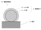
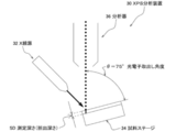
- FIG. 1 is a schematic cross-sectional view showing a preferred first embodiment of an electrode catalyst of the present invention. It is a schematic cross section which shows suitable 2nd Embodiment of the catalyst for electrodes of this invention. It is a schematic cross section which shows suitable 3rd Embodiment of the catalyst for electrodes of this invention. It is a schematic cross section which shows suitable 4th Embodiment of the catalyst for electrodes of this invention. It is a schematic diagram which shows schematic structure of the XPS apparatus for demonstrating the analysis conditions of the X-ray photoelectron spectroscopy (XPS) in this invention. It is a schematic diagram which shows suitable one Embodiment of the fuel cell stack of this invention.
- XPS X-ray photoelectron spectroscopy
- FIG. 7 is a graph illustrating a “rectangular wave potential sweep mode” in which the potential (vsRHE) of the rotating disk electrode WE is swept with respect to the reference electrode RE in the embodiment.
- FIG. 1 is a schematic cross-sectional view showing a first preferred embodiment of the electrode catalyst (core-shell catalyst) of the present invention.
- FIG. 2 is a schematic cross-sectional view showing a second preferred embodiment of the electrode catalyst of the present invention.
- FIG. 3 is a schematic cross-sectional view showing a third preferred embodiment of the electrode catalyst of the present invention.
- FIG. 4 is a schematic sectional view showing a fourth preferred embodiment of the electrode catalyst of the present invention.
- the electrode catalyst 10 of the first embodiment includes a carrier 2 and catalyst particles 3 having a so-called “core-shell structure” formed on the carrier 2. Further, the catalyst particle 3 has a so-called “core-shell structure” including a core part 4 formed on the carrier 2 and a shell part 6 formed on the core part 4. Further, the constituent elements (chemical composition) of the core portion and the constituent elements (chemical composition) of the shell portion 6 are different. In the case of the electrode catalyst 10 shown in FIG. 1, a substantially entire surface of the core portion 4 is covered with the shell portion 6.
- the core portion 4 includes Ti oxide and Pd (zero-valent metal state Pd), and the shell portion 6 includes Pt (zero-valent metal state Pt).
- Pd zero-valent metal state
- Pt zero-valent metal state Pt
- Ti oxide is present in the vicinity of Pt of the shell portion 6, so that the electrode catalyst 10 is equal to or more than this compared to the Pt / Pd / C catalyst.
- the catalyst activity (oxygen reduction activity) and durability can be contributed to cost reduction.
- the electrode catalyst 10A of the second embodiment shown in FIG. 2 has a part of the surface of the core part 4 covered with the shell part 6a, and the surface of the core part 4 is It is in a partially exposed state (for example, a state in which a part 4s of the surface of the core part 4 shown in FIG. 2 is exposed).
- the electrode catalyst 10 ⁇ / b> A shown in FIG. 2 has a shell portion 6 a partially formed on a part of the surface of the core portion 4.
- the shell portion may be formed on at least a part of the surface of the core portion as long as the effects of the present invention can be obtained. Even in this configuration, since the Ti oxide is present in the vicinity of Pt of the shell portion 6a, the electrode catalyst 10A has catalytic activity and durability equivalent to or higher than those of the Pt / Pd / C catalyst. And contribute to cost reduction.
- the main component of the core portion exposed surface 4s (analysis region near the surface measured by XPS) on the surface of the core portion 4 shown in FIG. 2 may be Ti oxide. That is, it may be in a state where the ratio (atom%) of the Ti oxide component is the highest among the constituent components of the core portion exposed surface 4s (analysis region in the vicinity of the surface measured by XPS). . Even in this case, since the Ti oxide exists in the vicinity of Pt of the shell portion 6a on the surface of the catalyst particle 3a, the effect of the present invention can be obtained. As in the electrode catalyst 10A shown in FIG.
- the method for preparing a catalyst having a structure in which the main component of the core portion exposed surface 4s on the surface of the core portion 4 is Ti oxide is not particularly limited, and is prepared by a known method. it can.
- the shell portion 6a is formed on the particles containing Pd and Ti oxide (particles that become the precursor of the core portion), by adopting the UPD method, among the surfaces of the particles containing Pd and Ti oxide
- the shell portion 6a can be selectively formed in a portion where Pd (zero-valent metal state Pd) is exposed.
- Electrode catalyst 10A1 A catalyst (hereinafter referred to as “electrode catalyst 10A1”) can be prepared.
- core part exposed surface 4s among the surfaces of core part 4 consists of Ti oxides, and core part exposed surface 4s among the surfaces of core part 4
- the other surface is preferably made of Pd (zero-valent metal state Pd).
- the electrode catalyst 10B of the third embodiment shown in FIG. 3 has a configuration in which an intermediate shell portion 5b is further disposed between the core portion 4 and the shell portion 6b. have.
- the intermediate shell portion 5b contains Pd.
- the shell part 6b is provided on the intermediate
- the shell part is preferable because it can be formed relatively easily on the intermediate shell part 5b in a good covering state.
- Pd zero-valent metal state Pd
- the intermediate shell portion 5b is more preferably made of only Pd (zero-valent metal state Pd).
- the electrode catalyst 10B has catalytic activity and durability equivalent to or higher than those of the Pt / Pd / C catalyst. And contribute to cost reduction.
- the electrode catalyst 10C shown in FIG. 4 includes an intermediate shell part (intermediate shell part 5c, shell part 5d) on a part of the surface of the core part 4, and A shell part (shell part 6c, shell part 6d) that covers the intermediate shell part is partially formed, and the surface of the core part 4 is partially exposed (for example, one surface of the core part 4 shown in FIG. 4). The portion 4s is exposed). More specifically, in the case of the electrode catalyst 10 ⁇ / b> C shown in FIG.
- an intermediate shell portion 5 c is formed on a part of the surface of the core portion 4, and the shell portion covers almost the entire surface of the intermediate shell portion 5 c. 6c is formed. Further, an intermediate shell portion 5d is formed on another part of the surface of the core portion 4, and a shell portion 6d that covers a part of the surface of the intermediate shell portion 5d is formed.
- a part of surface of the intermediate shell part 5d is coat
- the electrode catalyst 10C is compared with the Pt / Pd / C catalyst. It has equivalent or higher catalytic activity and durability, and can contribute to cost reduction.
- the main component of the core portion exposed surface 4s (analysis region in the vicinity of the surface measured by XPS) on the surface of the core portion 4 shown in FIG. 4 may be Ti oxide. That is, the Ti oxide component ratio (atom%) may be the highest among the constituent components of the core portion exposed surface 4s (analysis region near the surface measured by XPS). Even in this case, since the Ti oxide exists in the vicinity of Pt of the shell portion 6c on the surface of the catalyst particle 3c, the effect of the present invention can be obtained.
- the method for preparing a catalyst having a structure in which the main component of the core portion exposed surface 4s on the surface of the core portion 4 is Ti oxide is not particularly limited, and is prepared by a known method. it can.
- the intermediate shell portion 5c and the intermediate shell portion 5d are formed on particles containing Pd and Ti oxide (particles that serve as a precursor of the core portion)
- the Pd and Ti oxides are changed.
- the intermediate shell portion 5c and the intermediate shell portion 5d can be selectively formed on the surface made of Pd (Pd in a zero-valent metal state) among the surfaces of the contained particles.
- the surface of the intermediate shell portion 5c is adopted by adopting the UPD method.
- the shell portion 6c and the shell portion 6d can be selectively formed on the surface of the intermediate shell portion 5d.
- electrode catalyst 10C1 an electrode catalyst having a structure in which the shell portion 6c is selectively formed on the surface of the intermediate shell portion 5c.
- the core part exposed surface 4s among the surfaces of the core part 4 consists of Ti oxides, and the core part exposed surface 4s among the surfaces of the core part 4 is used.
- the other surface is preferably made of Pd (zero-valent metal state Pd). This makes it easier to selectively form the intermediate shell portion 5c and the intermediate shell portion 5d on the surface other than the core portion exposed surface 4s.
- Pd Pd in a zero-valent metal state
- An intermediate shell portion 5c mainly composed of Pd (zero-valent metal state Pd) and an intermediate shell portion 5d mainly composed of Pd (zero-valent metal state Pd) are formed on the main surface. It becomes a state.
- the electrode catalyst 10C1 since the chemical composition of the contact surface between the core part 4 and the intermediate shell part 5c and the chemical composition of the core part 4 and the intermediate shell part 5d are substantially the same, the core part 4 and the intermediate shell part 5c ( Alternatively, the intermediate shell portion 5d) appears to be integrated. That is, the electrode catalyst 10C1 has substantially the same configuration as the above-described electrode catalyst 10A1 (a modification of the electrode catalyst 10A of the second embodiment).
- the intermediate shell portion 5c containing Pd (zero-valent metal state Pd) as a main component has the highest proportion (atom%) of zero-valent metal state among the constituent components of the intermediate shell portion 5c. State.
- the intermediate shell portion 5d whose main component is Pd (zero-valent metal state Pd) is a state in which the proportion (atom%) of the zero-valent metal state Pd is the highest among the constituent components of the intermediate shell portion 5d.
- the electrode catalyst 10 shown in FIG. 1, the electrode catalyst 10A shown in FIG. 2, the electrode catalyst 10B shown in FIG. 3, and the electrode catalyst 10C shown in FIG. 4 will be described.
- the shell portion 6 (6a, 6b, 6c) is preferably composed only of Pt (zero-valent metal state Pt).
- Pt zero-valent metal state Pt
- the “Ti oxide” contained in the core portion 4 is TiO 2 having high chemical stability.
- the electrode catalysts 10, 10A, 10B, and 10C preferably satisfy the following conditions from the viewpoint of more reliably obtaining the effects of the present invention. That is, the electrode catalysts 10, 10A, 10B, and 10C have a ratio of Pt (zero-valent metal state Pt) in the analysis region near the surface when the surface vicinity is analyzed by X-ray photoelectron spectroscopy (XPS).
- Pt zero-valent metal state Pt
- R1 Pt (atom%), the ratio R1 Pd (atom%) of Pd (zero-valent metal state), and the ratio R1 Ti (atom%) of Ti derived from the Ti oxide are expressed by the following formula (1) It is preferable that the condition of 0.15 ⁇ ⁇ R1 Ti / (R1 Pt + R1 Pd + R1 Ti ) ⁇ ⁇ 0.75 (1)
- the inventors of the present invention have a structure (Ti oxide) that satisfies the condition of the above equation (1) for the chemical composition of the analysis region in the vicinity of the surfaces of the catalyst particles 3, 3a, 3b, 3c of the electrode catalysts 10, 10A, 10B, 10C. It has been found that the effect of the present invention can be obtained more reliably by adopting a configuration in which the ratio of (2) is relatively high.
- the present inventors have found that the presence of Ti oxide satisfying the above formula (1) on or near the surfaces of the catalyst particles 3, 3a, 3b, 3c It is presumed that the oxygen reduction reaction on the Pt of the shell parts 6, 6a, 6b, 6c, 6d of the particles 3, 3a, 3b, 3c is promoted. For example, when Ti oxide is present in the vicinity of Pt in the shell portion, the generated water generated by the reduction reaction of oxygen on Pt can quickly move from the Pt to the Ti oxide side. It is speculated that the reduction reaction is promoted.
- the value of ⁇ R1Ti / ( R1Pt + R1Pd + R1Ti ) ⁇ is a viewpoint that more reliably improves the catalyst activity (particularly, the initial Pt mass activity described later) compared to Pt / Pd / C. Is preferably 0.15 to 0.50, more preferably 0.25 to 0.50, and still more preferably 0.35 to 0.50. Furthermore, the value of ⁇ R1 Ti / (R1 Pt + R1 Pd + R1 Ti ) ⁇ is higher than that of Pt / Pd / C in terms of durability (particularly for “initial ECSA before evaluation test” in the durability evaluation described later). From the viewpoint of more reliably improving the “retention rate of ECSA after evaluation test”, it is preferably 0.15 to 0.50, and more preferably 0.15 to 0.40.
- the X-ray photoelectron spectroscopy is performed under the following analysis conditions (A1) to (A5).
- A2) Photoelectron extraction accuracy: ⁇ 75 ° C.
- the photoelectron extraction accuracy ⁇ of (A2) is, as shown in FIG. 5, the X-ray emitted from the X-ray source 32 is irradiated to the sample set on the sample stage 34 and is emitted from the sample.
- the angle ⁇ when the photoelectron is received by the spectroscope 36 corresponds to the angle between the light receiving axis of the spectrometer 36 and the surface of the sample layer of the sample stage 34.
- the electrode catalysts 10, 10A, 10B, and 10C preferably satisfy the following conditions from the viewpoint of more reliably obtaining the effects of the present invention. That is, the electrode catalysts 10, 10A, 10B, and 10C have a ratio of Pt (zero-valent metal state Pt) in the analysis region near the surface when the surface vicinity is analyzed by X-ray photoelectron spectroscopy (XPS). It is preferable that R1 Pt (atom%) and the ratio of Ti derived from Ti oxide R1 Ti (atom%) satisfy the condition of the following formula (2).
- the present inventors have found that the presence of Ti oxide satisfying the above formula (2) on or near the surfaces of the catalyst particles 3, 3a, 3b, 3c It is presumed that the oxygen reduction reaction is promoted on the Pt of the shells of the particles 3, 3a, 3b, 3c. For example, when Ti oxide is present in the vicinity of Pt of the shell parts 6, 6a, 6b, 6c, and 6d, the generated water generated by the oxygen reduction reaction on Pt is promptly formed on the Pt. It is assumed that the oxygen reduction reaction is promoted.
- the value of ⁇ R1 Pt / (R1 Pt + R1 Ti ) ⁇ is compared with Pt / Pd / C from the viewpoint of more reliably improving the catalytic activity (particularly, the initial Pt mass activity described later). 0.25 to 0.60, more preferably 0.35 to 0.60, still more preferably 0.50 to 0.60. Further, the value of ⁇ R1 Pt / (R1 Pt + R1 Ti ) ⁇ is the durability (particularly the maintenance rate of “ECSA after evaluation test” with respect to “initial ECSA before evaluation test” in durability evaluation described later). From the viewpoint of improving more reliably, it is preferably 0.25 to 0.60, more preferably 0.25 to 0.55.
- the XPS in the equation (2) is also measured under the conditions (A1) to (A6) described above.
- R1 Pt in the formula (1) or the formula (2) is preferably 19 atom% or more.
- the ratio of the part which consists of Pt (0t metal state Pt) with high catalytic activity on the surface of the electrode catalyst 10, 10A, 10B, 10C can be sufficiently secured, and the effect of the present invention can be obtained more reliably. be able to.
- R1 Pt is more preferably 30 atom% or more, and further preferably 30 atom% to 47 atom%.
- the ratio R1 Pd of Pd (Pd in a zero-valent metal state) in the formula (1) is preferably 36 atom% or less.
- the ratio of the portion made of Pd (zero-valent metal state Pd) on the surfaces of the electrode catalysts 10, 10A, 10B, and 10C increases, and the elution of Pd can be more reliably suppressed. . Therefore, the effect of the present invention can be obtained more reliably, for example, the durability (particularly, the maintenance rate of “ECSA after evaluation test” with respect to “initial ECSA before evaluation test” in durability evaluation described later) is further improved. It becomes like this.
- the core portion contains sufficient Pd.
- R1 Pd is more preferably 9 atom% to 36 atom%, and 17 atom % To 36 atom% is more preferable.
- the electrode catalyst 10, 10A, 10B, 10C are preferably R1 Ti in the formula (1) or Formula (2) is 18atom% ⁇ 71atom%. Further, from the same viewpoint, R1 Ti is further preferably 18atom% ⁇ 50atom%.
- the electrode catalysts 10, 10A, 10B, and 10C preferably have a Ti loading ratio L Ti (wt%) derived from Ti oxide measured by ICP emission analysis of 4.7 wt% or more.
- L Ti a Ti loading ratio derived from Ti oxide measured by ICP emission analysis of 4.7 wt% or more.
- the Ti loading rate L Ti (wt%) is preferably 9.5 wt% or less, and 9.0 wt% The following is more preferable.
- the Pt loading rate L Pt (wt%) and the Pd loading rate L Pd (wt%) measured by ICP emission analysis are the conditions of the following formula (3). Is preferably satisfied. L Pt / L Pd ⁇ 0.30 (3)
- the electrode catalysts 10, 10A, 10B, and 10C have an average crystallite size of 3 to 35.0 nm measured by powder X-ray diffraction (XRD). Is preferred. It is preferable that the average value of the crystallite size is 3 nm or more because it tends to be easier to form particles that will become the core portion 4 on the carrier. Furthermore, it is preferable that the average value of the crystallite size is 35.0 nm or less, because it becomes easier to form the particles serving as the core portion on the carrier in a highly dispersed state. From the same viewpoint, the average value of the crystallite size of the catalyst particles measured by powder X-ray diffraction (XRD) is more preferably 3 to 20 nm, and further preferably 3 nm or more and less than 20 nm.
- XRD powder X-ray diffraction
- a preferable range is appropriately set according to the design concept of the electrode catalyst. Further, the preferred ranges of the thicknesses of the intermediate shell portions 5b, 5c, and 5d are appropriately set according to the design concept of the electrode catalyst. For example, when it is intended to minimize the amount of Pt used to form the shell parts 6, 6 a, 6 b, 6 c, 6 d, it is a layer composed of one atom (one atomic layer). In this case, the thickness of the shell parts 6, 6a, 6b, 6c, 6d is as follows when the metal elements constituting the shell parts 6, 6a, 6b, 6c, 6d are one kind. The thickness is preferably equivalent to twice the diameter of one atom of the metal element (when approximating a sphere).
- a layer composed of one atom two or more kinds of atoms are juxtaposed on the surface of the core part 4. And a thickness corresponding to one atomic layer formed in this manner.
- the thickness is preferably 1 to 5 nm, and more preferably 2 to 10 nm.
- the shell parts 6, 6a, 6b, 6c, 6d contain Pt (Pt in a zero-valent metal state).
- the shell parts 6, 6a, 6b, 6c, and 6d are mainly composed of Pt (zero-valent metal state Pt) (preferably 50 wt%). More preferably, it is configured as 80 wt% or more, more preferably 90 wt% or more), and more preferably composed of Pt (zero-valent metal state Pt).
- the “average particle diameter” refers to an average value of the diameters of particles composed of an arbitrary number of particle groups, as observed with an electron micrograph.
- the thickness of the intermediate shell portions 5b, 5c, and 5d is preferably equal to or less than the thickness of the shell portion 6. This is preferable because the amount of Pd used can be reduced and the amount of Pd eluted when used as an electrode catalyst can be reduced.
- the intermediate shell portions 5b, 5c, 5d contain Pd (zero-valent metal state Pd).
- the intermediate shell portion 5 is mainly composed of Pd (zero-valent metal state Pd) (preferably 50 wt% or more, more preferably 80 wt%). As described above, it is preferably configured as 90 wt% or more, and more preferably configured from Pd (Pd in a zero-valent metal state).
- the carrier 2 is not particularly limited as long as it can carry a composite composed of the core part 4, the shell parts 6, 6a, 6b, 6c, 6d and the intermediate shell parts 5b, 5c, 5d and has a large surface area. Not. Furthermore, it is preferable that the support
- carrier 2 has a favorable dispersibility in the composition for gas diffusion electrode formation containing the electrode catalysts 10, 10A, 10B, and 10C, and has the outstanding electroconductivity.
- Carrier 2 is glassy carbon (GC), fine carbon, carbon black, graphite, carbon fiber, activated carbon, pulverized product of activated carbon, carbon nanofiber, carbon nanotube, etc., or glass or ceramics material such as oxide. It can be adopted as appropriate.
- a carbon-based material is preferable from the viewpoint of the adsorptivity with the core portion 4 and the BET specific surface area of the carrier 2.
- conductive carbon is preferable, and as the conductive carbon, conductive carbon black is particularly preferable. Examples of the conductive carbon black include trade names “Ketjen Black EC300J”, “Ketjen Black EC600”, “Carbon EPC” and the like (manufactured by Lion Chemical Co., Ltd.).
- the core part 4 is not particularly limited as long as it is configured to include Ti oxide and Pd (zero-valent metal state Pd).
- Pd zero-valent metal state Pd
- the electrode catalyst of the present invention has the electrode catalyst 10 shown in FIG. 1, the electrode catalyst 10A shown in FIG. 2, the electrode catalyst 10B shown in FIG. And the state in which at least 2 types of 10 C of electrode catalysts shown in FIG. 4 were mixed may be sufficient (not shown).
- the shell portion 6c and the shell portion 6d are separated from the same core portion 4 as in the electrode catalyst 10C of the fourth embodiment shown in FIG. May be mixed.
- the electrode catalyst of the present invention may be in a state where only the shell portion 6c shown in FIG. 4 is formed on the same core portion 4 within the range where the effects of the present invention can be obtained. Only the shell portion 6 d shown in FIG. 4 may be formed on the portion 4.
- the electrode catalyst 1 includes the electrode catalyst 10, the electrode catalyst 10A, the electrode catalyst 10B, and the electrode catalyst 10C on the support 2. In addition to at least one kind, a state in which “particles of only the core part 4 not covered with the shell part 6 (6a, 6b, 6c, 6d)” are supported (not shown) may be included. Furthermore, within the range where the effects of the present invention can be obtained, the electrode catalyst 1 includes, in addition to at least one of the above-described electrode catalyst 10, electrode catalyst 10A, electrode catalyst 10B, and electrode catalyst 10C.
- the electrode catalyst 1 includes, in addition to at least one of the above-described electrode catalyst 10, electrode catalyst 10A, electrode catalyst 10B, and electrode catalyst 10C. “Particles of only the core part 4 not covered with the shell part 6 (6a, 6b, 6c, 6d)” and “particles composed only of the constituent elements of the shell part 6 (6a, 6b, 6c, 6d)” However, the state carried independently may be included (not shown).
- the method for producing the electrode catalyst 10, 10A includes a “core particle forming step” in which core particles containing Pd and Ti oxide are formed on a carrier, and at least a surface of the core particles obtained through the core particle forming step. It includes a “shell portion forming step” in which the shell portions 6 and 6 a are partially formed.
- the electrode catalyst 10, 10 ⁇ / b> A is manufactured by sequentially supporting the core part 4 and the shell parts 6, 6 a constituting the catalyst particles 3, 3 a on the carrier 2.
- the method for producing the electrode catalyst 10 or 10A is not particularly limited as long as the method can support the catalyst particles 3 and 3a on the carrier 2.
- an impregnation method in which a solution containing a catalyst component is brought into contact with the support 2 and the support 2 is impregnated with the catalyst component
- a liquid phase reduction method in which a reducing agent is added to the solution containing the catalyst component
- an underpotential precipitation method examples of production methods that employ electrochemical deposition methods such as UPD), chemical reduction methods, reduction deposition methods using adsorbed hydrogen, surface leaching methods of alloy catalysts, displacement plating methods, sputtering methods, vacuum deposition methods, etc. it can.
- the raw materials and the mixing ratios of the raw materials are combined by combining the above-mentioned known methods so as to satisfy the above-mentioned preferred conditions such as formulas (1), (2), and (3). It is preferable to adjust the reaction conditions of the synthesis reaction. Also in the “shell part forming step”, the raw materials and their blends are combined by combining the above-mentioned known methods so as to satisfy the above-mentioned preferred conditions such as formulas (1), (2), and (3). It is preferable to adjust the ratio, synthesis reaction conditions, and the like.
- the electrode catalyst 10, 10A so as to satisfy the above-mentioned preferred conditions such as the formulas (1), (2), (3), for example, the chemical composition of the product (catalyst) Analyze the structure using various known analytical methods, feed back the results of the analysis to the manufacturing process, and prepare and select the raw materials to be selected, the mixing ratio of the raw materials, the synthetic reaction to be selected, the reaction conditions for the synthetic reaction, etc.
- the method of changing is given.
- the method for producing electrode catalysts 10B and 10C includes a “core particle forming step” in which core particles containing Pd and Ti oxide are formed on a carrier, and at least the surface of the core particles obtained through the core particle forming step.
- the electrode catalysts 10B and 10C are manufactured by sequentially supporting the core part 4, the intermediate shell parts 5b, 5c and 5d, and the shell parts 6b, 6c and 6d constituting the catalyst particles 3b and 3c on the carrier 2.
- the method for producing the electrode catalysts 10B and 10C is not particularly limited as long as the catalyst particles 3b and 3c can be supported on the carrier 2.
- an impregnation method in which a solution containing a catalyst component is brought into contact with the support 2 and the support 2 is impregnated with the catalyst component
- a liquid phase reduction method in which a reducing agent is added to the solution containing the catalyst component
- an underpotential precipitation method examples of production methods that employ electrochemical deposition methods such as UPD), chemical reduction methods, reduction deposition methods using adsorbed hydrogen, surface leaching methods of alloy catalysts, displacement plating methods, sputtering methods, vacuum deposition methods, etc. it can.
- the raw materials In the “core particle forming step”, the raw materials, the mixing ratio of the raw materials, It is preferable to adjust the reaction conditions of the synthesis reaction. Also, in the “intermediate shell portion forming step”, the raw materials are obtained by combining the above-described known methods so as to satisfy the above-mentioned preferred conditions such as formulas (1), (2), and (3). It is preferable to adjust the blending ratio, synthesis reaction conditions, and the like. Furthermore, also in the “shell part forming step”, the raw materials and their blends are combined by combining the above-mentioned known methods so as to satisfy the above-mentioned preferred conditions such as formulas (1), (2), and (3). It is preferable to adjust the ratio, synthesis reaction conditions, and the like.
- the electrode catalysts 10B and 10C so as to satisfy the above-described preferable conditions such as the formulas (1), (2), and (3), for example, the chemical composition and structure of the product (catalyst)
- the analysis results obtained are fed back to the manufacturing process, and the raw materials to be selected, the mixing ratio of the raw materials, the synthesis reaction to be selected, the reaction conditions for the synthesis reaction, etc. are prepared and changed. And how to do it.
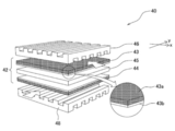
- FIG. 6 shows a gas diffusion electrode forming composition containing the electrode catalyst of the present invention, a gas diffusion electrode produced using this gas diffusion electrode forming composition, and a membrane / electrode assembly comprising this gas diffusion electrode
- FIG. 2 is a schematic diagram showing a preferred embodiment of a fuel cell stack including a MEMBRANE ELECTRODE ASSEMBLY (hereinafter abbreviated as “MEA” as necessary).
- MEA MEMBRANE ELECTRODE ASSEMBLY
- the fuel cell stack 40 includes an MEA 42 including an anode 43 that is a gas diffusion electrode, a cathode 44 that is a gas diffusion electrode, and an electrolyte membrane 45 disposed between these electrodes.
- the fuel cell stack 40 has a configuration in which the MEA 42 is sandwiched between a separator 46 and a separator 48.
- the gas diffusion electrode forming composition, the anode 43 and the cathode 44, and the MEA 42, which are members of the fuel cell stack 40 including the electrode catalyst of the present invention, will be described.
- the electrode catalyst of the present invention can be used as a so-called catalyst ink component to form the gas diffusion electrode forming composition of the present invention.
- the gas diffusion electrode forming composition of the present invention is characterized by containing the electrode catalyst of the present invention.
- the composition for forming a gas diffusion electrode contains the electrode catalyst and an ionomer solution as main components.
- the composition of the ionomer solution is not particularly limited.
- the ionomer solution may contain a polymer electrolyte having hydrogen ion conductivity, water, and alcohol.
- the polymer electrolyte contained in the ionomer solution is not particularly limited.
- the polymer electrolyte can be exemplified by a perfluorocarbon resin having a known sulfonic acid group or carboxylic acid group.
- a perfluorocarbon resin having a known sulfonic acid group or carboxylic acid group.
- polymer electrolytes having hydrogen ion conductivity Nafion (registered trademark, manufactured by DuPont), Aciplex (registered trademark, manufactured by Asahi Kasei Co., Ltd.), Flemion (registered trademark, manufactured by Asahi Glass Co., Ltd.) It can be illustrated.
- the composition for forming a gas diffusion electrode can be prepared by mixing, crushing, and stirring an electrode catalyst and an ionomer solution.
- the composition for forming a gas diffusion electrode can be prepared using a pulverizing mixer such as a ball mill or an ultrasonic disperser.
- the pulverization conditions and the stirring conditions when operating the pulverization mixer can be appropriately set according to the mode of the gas diffusion electrode forming composition.
- Each composition of the electrode catalyst, water, alcohol, and polymer electrolyte having hydrogen ion conductivity contained in the gas diffusion electrode forming composition has a good dispersion state of the electrode catalyst, and the electrode catalyst is gas diffused. It is appropriately set so that the entire catalyst layer of the electrode can be widely spread and the power generation performance of the fuel cell can be improved.
- the anode 43 which is a gas diffusion electrode, has a configuration including a gas diffusion layer 43a and a catalyst layer 43b formed on the surface of the gas diffusion layer 43a on the electrolyte membrane 45 side.
- the cathode 44 has a gas diffusion layer (not shown) and a catalyst layer (not shown) formed on the surface of the gas diffusion layer on the electrolyte membrane 45 side.
- the electrode catalyst of the present invention may be contained in at least one of the anode 43 and the cathode 44. Further, it is preferably contained in the catalyst layers of both the anode 43 and the cathode 44.
- the gas diffusion electrode of this invention can be used as an anode and can also be used as a cathode. Since the gas diffusion electrode (anode 43 and / or cathode 44) according to the present invention includes the electrode catalyst of the present invention, it is compared with the gas diffusion electrode including the Pt / Pd / C catalyst. It becomes easy to have a structure that has catalytic activity (polarization characteristics) and durability equal to or higher and can contribute to cost reduction.
- the catalyst layer 43b is a layer in the anode 43 where a chemical reaction is performed in which the hydrogen gas sent from the gas diffusion layer 43a is dissociated into hydrogen ions by the action of the electrode catalyst 10 contained in the catalyst layer 43b.
- the catalyst layer 43b includes, in the cathode 44, the catalyst 10 for an electrode in which the air (oxygen gas) sent from the gas diffusion layer 43a and the hydrogen ions that have moved through the electrolyte membrane from the anode 43 are contained in the catalyst layer 43b. It is a layer in which a chemical reaction is performed by bonding.
- the catalyst layer 43b is formed using the gas diffusion electrode forming composition.
- the catalyst layer 43b preferably has a large surface area so that the reaction between the electrode catalyst 10 and the hydrogen gas or air (oxygen gas) sent from the gas diffusion layer 43a can be sufficiently performed.
- the catalyst layer 43b is preferably formed so as to have a uniform thickness throughout. The thickness of the catalyst layer 43b may be appropriately adjusted and is not limited, but is preferably 2 to 200 ⁇ m.
- the gas diffusion layer provided in the anode 43 serving as the gas diffusion electrode and the cathode 44 serving as the gas diffusion electrode is introduced into the gas flow path formed between the separator 46 and the anode 43 from the outside of the fuel cell stack 40.
- This is a layer provided for diffusing the hydrogen gas and the air (oxygen gas) introduced into the gas flow path formed between the separator 48 and the cathode 44 into each catalyst layer.
- the gas diffusion layer has a role of supporting the catalyst layer and immobilizing it on the surface of the gas diffusion electrode.
- the gas diffusion layer has a function / structure that allows hydrogen gas or air (oxygen gas) to pass through well and reach the catalyst layer. For this reason, it is preferable that the gas diffusion layer has water repellency.
- the gas diffusion layer has a water repellent component such as polyethylene terephthalate (PTFE).
- the member which can be used for the gas diffusion layer is not particularly limited, and a known member used for the gas diffusion layer of the fuel cell electrode can be used.
- a known member used for the gas diffusion layer of the fuel cell electrode can be used.
- carbon paper, carbon paper as a main raw material, and carbon powder, ion-exchanged water as optional components, and a secondary material made of polyethylene terephthalate dispersion as a binder are applied to carbon paper.
- the anode 43 that is a gas diffusion electrode and the cathode 44 that is a gas diffusion electrode may include an intermediate layer (not shown) between the gas diffusion layer and the catalyst layer.
- the gas diffusion electrode of this invention should just be manufactured so that the electrode catalyst of this invention may become a structural component of a catalyst layer, and a manufacturing method is not specifically limited, A well-known manufacturing method is employable.
- the gas diffusion electrode is formed by applying a gas diffusion electrode forming composition containing an electrode catalyst, a polymer electrolyte having hydrogen ion conductivity, and an ionomer to the gas diffusion layer, and You may manufacture through the process of drying the gas diffusion layer with which the composition was apply
- An MEA 42 that is a preferred embodiment of the MEA of the present invention shown in FIG. 6 has a configuration including an anode 43, a cathode 44, and an electrolyte membrane 45.
- the MEA 42 has a configuration in which at least one of the anode 43 and the cathode 44 includes a gas diffusion electrode containing the electrode catalyst of the present invention. Since the MEA 42 includes the gas diffusion electrode according to the present invention, the MEA 42 has battery characteristics and durability equivalent to or higher than those of the MEA including the Pt / Pd / C catalyst in the gas diffusion electrode, and is low It becomes easy to set it as the structure which can contribute to cost reduction.
- the MEA 42 can be manufactured by laminating the anode 43, the electrolyte 300, and the cathode 44 in this order, and then press-bonding them.
- a fuel cell stack 40 which is a preferred embodiment of the fuel cell stack of the present invention shown in FIG. 6 has a configuration in which a separator 46 is disposed outside the anode 43 of the MEA 42 and a separator 48 is disposed outside the cathode 44.
- One unit cell single cell
- this unit cell single cell
- the fuel cell stack 40 includes the MEA 42 according to the present invention
- the fuel cell stack 40 has a cell characteristic equal to or higher than that of the fuel cell stack including at least one MEA including the Pt / Pd / C catalyst in the gas diffusion electrode.
- the fuel cell system is completed by attaching and assembling peripheral devices to the fuel cell stack 40.
- This Pt / Pd / Pd + TiO 2 / C powder is an intermediate composed of Pd (zero-valent metal state Pd) in the surface of the following Pd / Pd + TiO 2 / C powder by adjusting the conditions of the UPD method.
- This is a powder in which a shell portion made of Pt is selectively formed in a layer.
- the present inventors presume that the electrode catalyst 10C1 is a modified embodiment of the electrode catalyst 10C of the fourth embodiment shown in FIG.
- the electrode catalyst 10C1 has substantially the same configuration as the electrode catalyst 10A1, which is a modification of the electrode catalyst 10A of the second embodiment shown in FIG.
- the present inventors have a configuration of precursor particles before the shell portions 6c and 6d are formed in the electrode catalyst 10C1 which is a modification of the electrode catalyst 10C of the fourth embodiment shown in FIG. I guess.
- Pd + TiO 2 / C powder with a core particle composed of Pd and Ti oxide (TiO 2 ) supported on carbon black powder ⁇ trade name “NE-H002T0-DE”, manufactured by NE CHEMCAT) ⁇ Prepared.
- This Pd + TiO 2 / C powder was prepared by heat-treating a powder containing a commercially available carbon black powder (specific surface area 750 to 850 m 2 / g), a commercially available Ti compound, and a Pd compound in a reducing atmosphere. is there.
- the core particles of the Pd + TiO 2 / C powder were composed of Pd and Ti oxide (TiO 2 ).
- the Pt loading rate L Pt (wt%), the Pd loading rate L Pd (wt%), and the Ti loading rate L Ti (wt%) were measured by the following methods.
- the electrode catalyst of Example 1 was immersed in aqua regia to dissolve the metal. Next, insoluble component carbon was removed from the aqua regia. Next, aqua regia without carbon was analyzed by ICP. The results of ICP analysis are shown in Table 1.
- Example 2 to Example 7 XPS analysis results (R1 Pt , R1 Pd , R1 Ti ) of the surface of the electrode catalyst shown in Table 1, ICP analysis results (L Pt , L Pd , L Ti ) of the entire catalyst particles, XPS analysis of the surface of the catalyst particles
- electrode catalysts of Examples 2 to 7 were produced.
- XPS analysis and ICP analysis were also performed under the same conditions as in Example 1.
- Pd / C powder [Core particle supported carbon “Pd / C” powder] Pd / C powder ⁇ trade name “NE-H0200-DE”, manufactured by NE CHEMCAT) ⁇ in which core particles made of Pd were supported on carbon black powder was prepared.
- This Pd / C powder was prepared as follows. First, in a liquid obtained by preparing a liquid mixture of commercially available carbon black powder (specific surface area 750 to 850 m 2 / g), sodium tetrachloropalladium (II) and water, and adding a reducing agent to this. Then, palladium ions were reduced to obtain a powder in which Pd particles were supported on a carbon black powder.
- the powder in which the Pd particles are supported on the carbon black powder is subjected to a heat treatment in a reducing atmosphere similar to the case where the core particle-supported carbon “Pd + TiO 2 / C” powder of Example 1 is prepared.
- C powder was obtained.
- XPS analysis and ICP analysis were performed under the same conditions as those of the electrode catalyst of Example 1. The results are shown in Table 1.
- a shell part layer made of Pt was formed on at least a part of the surface of the core part particle made of Pd. It was confirmed that the catalyst particles having the core-shell structure were supported on a conductive carbon support.
- Electrode About 8.0 mg of electrode catalyst powder of Examples 1 to 7 and Comparative Example 1 was weighed and placed in a sample bottle together with 2.5 mL of ultrapure water. Mixing while irradiating with sound waves, an electrode catalyst slurry (suspension) was prepared. Next, 10.0 mL of ultrapure water and 20 ⁇ L of a 10 wt% Nafion (registered trademark) aqueous dispersion (trade name “DE1020CS” manufactured by Wako Chemical Co., Ltd.) are mixed in another container to prepare a Nafion-ultrapure aqueous solution. did.
- a 10 wt% Nafion (registered trademark) aqueous dispersion trade name “DE1020CS” manufactured by Wako Chemical Co., Ltd.
- FIG. 7 is a schematic diagram showing a schematic configuration of a rotating disk electrode measuring apparatus 50 used in the rotating disk electrode method (RDE method).
- the rotating disk electrode measuring apparatus 50 mainly includes a measurement cell 51, a reference electrode RE, a counter electrode CE, and a rotating disk electrode WE. Furthermore, when evaluating a catalyst, electrolyte solution ES is put into the measurement cell 51.
- the measurement cell 51 has a substantially cylindrical shape having an opening on the upper surface, and a fixing member 52 for the rotating disk electrode WE that also serves as a lid capable of gas sealing is disposed in the opening.
- a gas sealable opening for fixing the electrode main body portion of the rotating disk electrode WE while being inserted into the measurement cell 51 is provided at the center of the fixing member 52.
- a substantially L-shaped Lugin tube 53 is arranged next to the measurement cell 51.
- one end portion of the Luggin tube 53 has a Luggin capillary structure, and is inserted into the measurement cell 51, so that the electrolyte ES of the measurement cell 51 also enters the Luggin tube 53.
- the other end of the Lugin tube 53 has an opening, and the reference electrode RE is inserted into the Lugin tube 53 through the opening.
- “Model HSV110” manufactured by Hokuto Denko Co., Ltd. was used as the rotating disk electrode measuring device 50.
- an Ag / AgCl saturated electrode was used as the reference electrode RE, a Pt mesh with Pt black was used as the counter electrode CE, and an electrode having a diameter of 5.0 mm ⁇ and an area of 19.6 mm 2 was used as the rotating disk electrode WE. . Furthermore, using the HCl0 4 of 0.1M as the electrolyte ES.
- CV measurement was performed for 3 cycles in the “triangular wave potential sweep mode” in which the potential (vsRHE) of the rotating disk electrode WE was set to the measurement start potential +119 mV, +50 mV to 1200 mV, and the scanning speed was 20 mV / sec.
- the rotational speed of the rotating disk electrode WE was 1600 rpm.
- the rotating disk electrode was rotated 10 times in “triangular wave potential sweep mode” with a scanning potential of 135 to 1085 mV vs RHE and a scanning speed of 10 mV / sec.
- CV measurement was performed under the condition that the rotational speed of WE was 1600 rpm.
- the current value at the potential of the rotating disk electrode WE + 900 mV vs RHE was recorded.
- the rotational speed of the rotating disk electrode WE was set to 400 rpm, 625 rpm, 900 rpm, 1225 rpm, 2025 rpm, 2500 rpm, and 3025 rpm, respectively, and oxygen reduction (ORR) current measurement was performed for each cycle.
- ORR oxygen reduction
- Pt mass activity (Mass Act) (mA/ ⁇ g-Pt@0.9V) was calculated.
- the results obtained for Examples 1 to 7 and Comparative Example 1 are shown in Table 1.
- Table 1 the Pt mass activity of Examples 1 to 5 and Comparative Example 2 when the Pt mass activity (Mass Act) of Comparative Example 1 (Pt / Pd / C catalyst) is 1.00.
- the relative value of (Mass Act) was shown.
- V-1) [Initial ECSA measurement]
- I Potential sweep process The potential (vsRHE) of the rotating disk electrode WE with respect to the reference electrode RE was swept in a so-called "rectangular wave potential sweep mode" shown in FIG. More specifically, a potential sweep was performed for 6 cycles with the operation shown in (A) to (D) below as one cycle.
- A Potential at start of sweep: +600 mV
- B Sweep from +600 mV to +1000 mV
- C Hold potential at +1000 mV for 3 seconds
- D Sweep from +1000 mV to +600 mV
- E Hold potential at +600 mV 3 seconds.
- the values of the catalyst for electrodes of Example 1 and Examples 2 to 6 [ ⁇ R1 Ti / (R1 Pt + R1 Pd + R1 Ti ) ⁇ are 0.25 to 0.50, ⁇ R1 Ti / (R1 Pt + R1) Ti ) ⁇ value of 0.35 to 0.60] has a Pt mass activity of about 2 to 3 times that of the electrode catalyst of Comparative Example 1 (Pt / Pd / C catalyst). It was revealed that it has excellent catalytic activity. Further, from the results of “the relative value of the retention rate of ESCA” obtained from the initial ECSA value and the ECSA measurement value after 12420 cycles of potential sweep shown in Table 1, the electrodes of Examples 1 to 6 were used.
- the catalyst [ ⁇ R1Ti / ( R1Pt + R1Pd + R1Ti ) ⁇ has a value of 0.15 to 0.50 and ⁇ R1Ti / ( R1Pt + R1Ti ) ⁇ has a value of 0.25 to 0.60].
- the ECSA value and ECSA maintenance rate after the number of potential sweeps of 12420 cycles were equal or higher (about 1.3 times to about 1.5 times). It was revealed that it had excellent durability.
- the electrode catalyst of the present example has equivalent or higher catalytic activity and durability than the Pt / Pd / C catalyst. Furthermore, since the electrode catalyst of this example employs a Ti oxide as a part of the material of the core portion, it has been clarified that the amount of platinum used can be reduced and the cost can be reduced.
- the electrode catalyst of the present invention has equivalent or higher catalytic activity and durability than the Pt / Pd / C catalyst, and can contribute to cost reduction. Accordingly, the present invention is an electrode catalyst that can be applied not only to the electric equipment industry such as fuel cells, fuel cell vehicles, and portable mobiles, but also to energy farms, cogeneration systems, etc. Contribute to development.
Abstract
Description
また本発明は、上記電極用触媒粒子を含む、ガス拡散電極形成用組成物、膜・電極接合体、及び、燃料電池スタックに関する。
例えば、典型的な従来の触媒としては、導電性カーボン粉末上にPt微粒子を担持させた「Pt担持カーボン触媒」(以下、必要に応じ「Pt/C触媒」という)が知られている(例えば、N.E.CHEMCAT社製のPt担持率50wt%のPt/C触媒、商品名:「NE-F50」など)。
PEFCの製造コストの中でPt等の貴金属触媒が占めるコストの割合は大きく、PEFCの低コスト化、PEFCの普及に向けた課題になっている。
この課題を解決するために、触媒の低貴金属化技術、又は、脱貴金属化技術の研究開発が進められている。
例えば、特許文献1には、パラジウム(Pd)又はPd合金(コア部に相当)がPt原子の原子的薄層(シェル部に相当)によって被覆された構成を有する粒子複合材(コアシェル触媒粒子)が開示されている。更に、この特許文献1には、実施例としてコア部がPd粒子で、シェル部がPtからなる層であるコアシェル触媒粒子が記載されている。
例えば、Ti酸化物をコア部の構成材料として含む構成が提案されている(例えば、特許文献2~5)。
特許文献3には、Ti酸化物をコア部、Ptなどをシェル部とする白金-金属酸化物複合粒子が開示されている(例えば、特許文献3、段落番号0010)。
特許文献5には、Ti酸化物をからなる内部粒子(コア部)とし、内部粒子の表面の少なくとも一部を被覆するPtを含む最外層(シェル部)を有する構成の燃料電池用触媒が提案されている(例えば、特許文献5、図1、段落番号0031~0039)。また、特許文献5には、参考例3として結晶性のTiO2の表面に白金が存在していることを、、高角度散乱暗視野法(High-Angle Annular Dark-Field:以下、必要に応じて「HAADF」と称する)による測定、及び、エネルギー分散型X線分光法(Energy Dispersive X-ray Spectroscopy:以下、必要に応じて「EDS」と称する)による測定により確認できたと記載されている(例えば、特許文献5、段落番号0116、図4、図5)。
より詳しくは、特許文献4については、実施例として記載され性能評価されているのは、「シェル部/コア部」で表記すると、「Pt/Ag」(特許文献4、実施例1、実施例4)、「Pt/Au」(特許文献4、実施例2、実施例3)の構成のみである。性能評価についても「RDE(回転リングディスク電極)による電気化学試験において、高い比活性が得られる」とだけ記載されており、どの程度の性能が得られるか詳細は不明である。
また、本発明は、上記電極用触媒を含む、ガス拡散電極形成用組成物、ガス拡散電極、膜・電極接合体(MEA)、及び、燃料電池スタックを提供することを目的とする。
その結果、本発明者らは、少なくともTi酸化物(特にTiO2)とPd(Pd単体、即ち0価の金属状態のPd)とを含むコア部、Pt(0価の金属状態のPt)を主成分とするシェル部からなる構成が有効であることを見出し、本発明を完成するに至った。
より具体的には、本発明は、以下の技術的事項から構成される。
(N1)導電性を有する担体と、
前記担体上に担持される触媒粒子と、
を含んでおり、
前記触媒粒子が、前記担体上に形成されるコア部と、前記コア部上に形成されるシェル部と、を有しており、
前記コア部にはTi酸化物とPd(0価の金属状態のPd)とが含まれており、
前記シェル部にはPt(0価の金属状態のPt)が含まれている、電極用触媒を提供する。
より詳しくは、「シェル部の構成/コア部の構成/担体の構成」と表記する。更に、触媒粒子が、コア部とシェル部との間に中間シェル部を更に有する構成の場合には、「シェル部の構成/中間シェル部の構成/コア部の構成/担体の構成」と表記する。
例えば、電極用触媒の構成が、「Ptからなるシェル部、Ti酸化物とPdとを主成分とするコア部、導電性カーボンからなる担体」を有する構成の場合、「Pt/Pd+TiOx/C」と表記する。また、電極用触媒の構成が、「Ptからなるシェル部、Pdからなる中間シェル部、Ti酸化物とPdとを主成分とするコア部、導電性カーボンからなる担体」を有する構成の場合、「Pt/Pd/Pd+TiOx/C」と表記する。ここで、「TiOx」の「x」は、Ti原子に対するO原子の化学量論係数を示す。
(N2)X線光電子分光分析法(XPS)により測定される表面近傍の分析領域における、前記Ptの割合R1Pt(atom%)と、前記Pdの割合R1Pd(atom%)と、前記Ti酸化物に由来するTiの割合R1Ti(atom%)とが、下記式(1)の条件を満たしていることが好ましい。
0.15≦{R1Ti/(R1Pt+R1Pd+R1Ti)}≦0.75・・・(1)
詳細なメカニズムは十分に解明されていないが、本発明者らは、触媒粒子の表面又は表面近傍に上記(1)式を満たすTi酸化物が存在することにより、触媒粒子のシェル部のPt上での酸素の還元反応が促進されていると推察している。例えば、Ti酸化物がシェル部のPtの近傍に存在することにより、Pt上での酸素の還元反応により生成する生成水が当該Pt上から速やかにTi酸化物の側に移動できるようになり酸素の還元反応が促進されていると推察している。
{R1Ti/(R1Pt+R1Pd+R1Ti)}が0.15未満となると上述のTi酸化物の添加による触媒性能の向上効果の度合いが小さくなる傾向にある。また{R1Ti/(R1Pt+R1Pd+R1Ti)}が0.75を超えると、電極用触媒の表面において触媒活性の高いPtからなる部分の割合が減り上述のTi酸化物の添加による触媒性能の向上効果の度合いが小さくなる傾向にある。
更に、本発明において、Pt/Pd/Cに比較して、耐久性(特に、後述の耐久性評価における「評価試験前の初期のECSA」に対する「評価試験後のECSA」の維持率)をより確実に向上させる観点からは、{R1Ti/(R1Pt+R1Pd+R1Ti)}は0.15~0.50であることが好ましく、0.15~0.40であることがより好ましい。
(A1)X線源:単色化AlKα
(A2)光電子取出確度:θ=75℃(後述する図5を参照)
(A3)帯電補正:C1sピークエネルギーを284.8eVとして補正
(A4)分析領域:200μm
(A5)分析時のチャンバ圧力:約1×10⁻⁶Pa
(N3)X線光電子分光分析法(XPS)により測定される表面近傍の分析領域における、前記Ptの割合R1Pt(atom%)と、前記Ti酸化物に由来するTiの割合R1Ti(atom%)とが、下記式(2)の条件を満たしていることが好ましい。
0.25≦{R1Ti/(R1Pt+R1Ti)}≦0.80・・・(2)
詳細なメカニズムは十分に解明されていないが、本発明者らは、触媒粒子の表面又は表面近傍に上記(2)式を満たすTi酸化物が存在することにより、触媒粒子のシェル部のPt上での酸素の還元反応が促進されていると推察している。例えば、Ti酸化物がシェル部のPtの近傍に存在することにより、Pt上での酸素の還元反応により生成する生成水が当該Pt上から速やかにTi酸化物の側に移動できるようになり酸素の還元反応が促進されていると推察している。
更に、本発明において、Pt/Pd/Cに比較して、耐久性(特に、後述の耐久性評価における「評価試験前の初期のECSA」に対する「評価試験後のECSA」の維持率)をより確実に向上させる観点からは、{R1Pt/(R1Pt+R1Ti)}の値は、0.25~0.60であることが好ましく、0.25~0.55であることがより好ましい。
なお、(2)式おけるXPSも先に述べた(A1)~(A6)条件で測定される。
(N4)前記式(1)又は前記式(2)における前記R1Ptが19atom%以上であることが好ましい。
これにより、(N2)又は(N3)に記載の電極用触媒について、当該電極用触媒の表面において触媒活性の高いPtからなる部分の割合を十分に確保でき、本発明の効果をより確実に得ることができる。
更に同様の観点から、R1Ptは、30atom%以上であることがより好ましく、30atom%~47atom%であることが更に好ましい。
(N5)前記式(1)における前記Pdの割合R1Pdが36atom%以下であることが好ましい。
これにより、(N2)又は(N4)に記載の電極用触媒について、電極用触媒の表面においてPdからなる部分の割合が減る傾向が大きくなり、Pdの溶出がより確実に抑制できるようになる。そのため、耐久性(特に、後述の耐久性評価における「評価試験前の初期のECSA」に対する「評価試験後のECSA」の維持率)がより向上するなど、本発明の効果がより確実に得られるようになる。
また、シェル部のPt部分の触媒活性を十分に得る観点からコア部に十分なPdが含有されていることが好ましく、この観点からR1Pdは9atom%~36atom%であることがより好ましく、17atom%~36atom%であることが更に好ましい。
(N6)前記式(1)又は前記式(2)における前記R1Tiが18atom%~71atom%であることが好ましい。更に、同様の観点から、R1Tiは18atom%~50atom%であることが更に好ましい。
(N7)ICP発光分析により測定される前記Ti酸化物に由来するTiの担持率LTi(wt%)が4.7wt%以上であることが好ましい。
このように電極用触媒を構成することにより、コア部のPd使用量を低減することができ、低コスト化により容易に寄与することができるようになる。一方、触媒粒子の電子電導性を容易に確保する観点からは、Tiの担持率LTi(wt%)は9.5wt%以下であることが好ましく、9.0wt%以下であることがより好ましい。
(N8)ICP発光分析により測定されるPt担持率LPt(wt%)と、Pd担持率LPd(wt%)とが下記式(3)の条件を満たしていることが好ましい。
LPt/LPd≧0.30・・・(3)
上記(3)式をさらに満たすように電極用触媒を構成することにより、コア部のPdの使用量が低減できるようになるため、より低コスト化に寄与することができるようになる。
(N9)前記触媒粒子が、前記コア部と、前記シェル部との間に配置される中間シェル部を更に有しており、
前記中間シェル部にはPd(0価の金属状態のPd)が含まれている構成を有していてもよい。
このように、コア部とシェル部との間に、Pdを含む(好ましくはPdを主成分として含む)中間シェル部を配置する構成とした場合、中間シェル部上にシェル部を形成する際に、公知のUPD(アンダーポテンシャルデポジション)法を採用することができ、シェル部を中間シェル部上に良好な被覆状態で比較的容易に形成できるので好ましい。
Pdの格子定数(3.89オングストローム)がPtの格子定数(3.92オングストローム)に近いので中間シェル部上にシェル部のPtを比較的安定した状態で形成できることが期待できる。また、コア部と中間シェル部とが共通成分であるPdを含む構成となっているため、コア部と中間シェル部との親和性も比較的良好なものとできるので好ましい。
(N10)前記触媒粒子の表面の一部にTi酸化物が露出していてもよい。
この場合でも、触媒粒子の表面において、シェル部のPtの近傍にTi酸化物が存在するため本発明の効果を得ることができる。
(N11)粉末X線回折(XRD)により測定される前記触媒粒子の結晶子サイズの平均値が3~35.0nmであることが好ましい。
結晶子サイズの平均値が3nm以上であると、担体上にコア部となる粒子を形成することがより容易になる傾向が大きくなるので好ましい。更に、結晶子サイズの平均値が35.0nm以下であると、担体上にコア部となる粒子を高分散状態で形成することがより容易になるので好ましい。同様の観点から、粉末X線回折(XRD)により測定される前記触媒粒子の結晶子サイズの平均値は3~20nmであることがより好ましく、3nm以上20nm未満であることが更に好ましい。
なお、本発明においては、中間シェル部がPtからなり、シェル部がPdからなり、かつ、中間シェル部がPt原子層で1層~2層となる場合、XRDによってPt(220)面のピークがみえないので、コア部のPd(220)面のピーク(又は中間シェル部を有する構成の場合は当該中間シェル部のPd(220)面のピーク)から算出した平均値を触媒粒子の結晶子サイズの平均値としている。
(N12)上述の(N1)~(N11)いずれか1に記載の電極用触媒が含有されている、ガス拡散電極形成用組成物を提供する。
本発明のガス拡散電極形成用組成物は、本発明の電極用触媒を含んでいるため、Pt/Pd/C触媒を含むガス拡散電極形成用組成物と比較し、これと同等以上の触媒活性(分極特性)、耐久性を有し、かつ、低コスト化に寄与できるガス拡散電極を容易に製造することができる。
(N13)上述の(N1)~(N11)いずれか1に記載の電極用触媒が含有されている、又は、上述の(N12)に記載のガス拡散電極形成用組成物を使用して形成されている、ガス拡散電極を提供する。
本発明のガス拡散電極は、本発明の電極用触媒を含んで構成されている。或いは、本発明のガス拡散電極は、本発明のガス拡散電極形成用組成物を使用して形成されている。そのため、Pt/Pd/C触媒を含むガス拡散電極と比較し、これと同等以上の触媒活性(分極特性)、耐久性を有し、かつ、低コスト化に寄与できる構成とすることが容易となる。
(N14)上述の(N13)記載のガス拡散電極が含まれている、膜・電極接合体(MEA)を提供する。
本発明の膜・電極接合体(MEA)は、本発明のガス拡散電極を含んでいるため、Pt/Pd/C触媒をガス拡散電極に含むMEAと比較し、これと同等以上の電池特性、耐久性を有し、かつ、低コスト化に寄与できる構成とすることが容易となる。
(N15)上述の(N14)記載の膜・電極接合体(MEA)が含まれていることを特徴とする燃料電池スタックを提供する。
本発明の燃料電池スタックは、本発明の膜・電極接合体(MEA)を含んでいるため、Pt/Pd/C触媒をガス拡散電極に含むMEAを少なくとも1つ含む燃料電池スタックと比較し、これと同等以上の電池特性、耐久性を有し、かつ、低コスト化に寄与できる構成とすることが容易となる。
また、本発明によれば、かかる電極用触媒を含む、ガス拡散電極形成用組成物、ガス拡散電極、膜・電極接合体(MEA)、燃料電池スタックが提供される。
<電極用触媒>
図1は、本発明の電極用触媒(コアシェル触媒)の好適な第1実施形態を示す模式断面図である。また、図2は、本発明の電極用触媒の好適な第2実施形態を示す模式断面図である。更に、図3は、本発明の電極用触媒の好適な第3実施形態を示す模式断面図である。また、図4は、本発明の電極用触媒の好適な第4実施形態を示す模式断面図である。
以下、図1を参照しながら本発明の電極用触媒(コアシェル触媒)の第1実施形態主な構成について説明する。
図1に示されるように、第1実施形態の電極用触媒10は、担体2と、担体2上に形成されるいわゆる「コアシェル構造」を有する触媒粒子3を含んでいる。
更に、触媒粒子3は、担体2上に形成されるコア部4と、コア部4上に形成されるシェル部6とを含む、いわゆる「コアシェル構造」を有する。
また、コア部の構成元素(化学組成)と、シェル部6との構成元素(化学組成)は異なる構成となっている。図1に示す電極用触媒10の場合、シェル部6によってコア部4の表面の略全域が被覆された状態となっている。
コア部4にはTi酸化物とPd(0価の金属状態のPd)とが含まれており、シェル部6にはPt(0価の金属状態のPt)が含まれている。この構成(Pt/Pd+TiOx/C)とすることにより、Ti酸化物がシェル部6のPtの近傍に存在するため、電極用触媒10は、Pt/Pd/C触媒と比較し、これと同等以上の触媒活性(酸素還元活性)、耐久性を有し、かつ、低コスト化に寄与できる。
以下、図2を参照しながら本発明の電極用触媒の第2実施形態主な構成について説明する。
図1に示した電極用触媒10と比較し、図2に示す第2実施形態の電極用触媒10Aは、コア部4の表面の一部がシェル部6aにより被覆され、コア部4の表面が部分的に露出した状態(例えば、図2に示すコア部4の表面の一部4sが露出した状態)となっている。別の表現をすれば、図2に示す電極用触媒10Aは、コア部4の表面の一部の上にシェル部6aが部分的に形成されている。
このように、本発明の電極用触媒は、本発明の効果を得られる範囲において、コア部の表面の少なくとも一部の上にシェル部が形成されていてもよい。この構成であっても、Ti酸化物がシェル部6aのPtの近傍に存在するため、電極用触媒10Aは、Pt/Pd/C触媒と比較し、これと同等以上の触媒活性、耐久性を有し、かつ、低コスト化に寄与できる。
図2に示した電極用触媒10Aのように、コア部4の表面のコア部露出面4sの主成分がTi酸化物である構成の触媒を調製する手法は特に限定されず公知の手法により調製できる。例えば、PdとTi酸化物を含む粒子(コア部の前駆体となる粒子)にシェル部6aを形成する際に、UPD法を採用することにより、PdとTi酸化物を含む粒子の表面のうちPd(0価の金属状態のPd)が露出している部分にシェル部6aを選択的に形成することができる。
なお、電極触媒10A1(電極触媒10Aの変形態様)については、コア部4の表面のうちコア部露出面4sはTi酸化物からなることが好ましく、コア部4の表面のうちコア部露出面4s以外の表面はPd(0価の金属状態のPd)からなることが好ましい。これにより、コア部露出面4s以外の表面にシェル部6aを選択的形成することがより容易になる。
以下、図3を参照しながら本発明の電極用触媒の第3実施形態主な構成について説明する。
図1に示した電極用触媒10と比較し、図3に示す第3実施形態の電極用触媒10Bは、コア部4と、シェル部6bとの間に中間シェル部5bが更に配置された構成を有している。
また中間シェル部5bにはPdが含まれている。
このように、コア部4とシェル部6bとの間に、Pd(0価の金属状態のPd)を含む中間シェル部5bを配置する構成とした場合、中間シェル部5b上にシェル部6bを形成する際に、公知のシェル部の形成法、例えば、UPD法を採用することができ、シェル部を中間シェル部5b上に良好な被覆状態で比較的容易に形成できるので好ましい。更に、中間シェル部5bを配置する構成とした場合、Pd(0価の金属状態のPd)を主成分(中間シェル部5bの構成成分の中で0価の金属状態のPdの割合(atom%)が最も高い状態)として含むようにすることが好ましい。同様の観点から、ここで中間シェル部5bはPd(0価の金属状態のPd)のみからなることがより好ましい。
この構成であっても、Ti酸化物がシェル部6bのPtの近傍に存在するため、電極用触媒10Bは、Pt/Pd/C触媒と比較し、これと同等以上の触媒活性、耐久性を有し、かつ、低コスト化に寄与できる。
以下、図4を参照しながら本発明の電極用触媒の第4実施形態の主な構成について説明する。
図3に示した電極用触媒10Bと比較し、図4に示す電極用触媒10Cは、コア部4の表面の一部の上に中間シェル部(中間シェル部5c、シェル部5d)と、当該中間シェル部を覆うシェル部(シェル部6c、シェル部6d)とが部分的に形成され、コア部4の表面が部分的に露出した状態(例えば、図4に示すコア部4の表面の一部4sが露出した状態)となっている。
より詳しくは、図4に示す電極用触媒10Cの場合、コア部4の表面の一部の上に中間シェル部5cが形成されており、当該中間シェル部5cの表面のほぼ全面を覆うシェル部6cが形成されている。また、コア部4の表面の他の一部の上には中間シェル部5dが形成されており、中間シェル部5dの表面の一部を覆うシェル部6dが形成されている。
この構成であっても、Ti酸化物がシェル部6cのPtの近傍、シェル部6dのPtの近傍にそれぞれ存在するため、電極用触媒10Cは、Pt/Pd/C触媒と比較し、これと同等以上の触媒活性、耐久性を有し、かつ、低コスト化に寄与できる。
更にこの場合、図4に示すコア部4の表面のコア部露出面4s(XPSにより測定される表面近傍の分析領域)の主成分がTi酸化物であってもよい。すなわち、コア部露出面4s(XPSにより測定される表面近傍の分析領域)の構成成分のうちTi酸化物成分の割合(atom%)が最も高い状態であってもよい。この場合でも、触媒粒子3cの表面において、シェル部6cのPtの近傍にTi酸化物が存在する構成となるため本発明の効果を得ることができる。
なお、電極触媒10C1(電極触媒10Cの変形態様)については、コア部4の表面のうちコア部露出面4sはTi酸化物からなることが好ましく、コア部4の表面のうちコア部露出面4s以外の表面はPd(0価の金属状態のPd)からなることが好ましい。これにより、コア部露出面4s以外の表面に中間シェル部5c、中間シェル部5dを選択的形成することがより容易になる。
以下、図1に示した電極用触媒10、図2に示した電極用触媒10A、図3に示した電極用触媒10B、及び、図4に示した電極用触媒10Cについて、共通の特徴を説明する。
シェル部6(6a、6b、6c)は良好な触媒活性(水素酸化活性又は酸素還元活性)を容易に得る観点から、Pt(0価の金属状態のPt)のみからなることが好ましい。
また、本発明の効果をより確実に得る観点から、コア部4に含まれる「Ti酸化物」は、化学的に安定性の高いTiO2であることが好ましい。
即ち、電極用触媒10、10A、10B、10Cは、X線光電子分光分析法(XPS)で表面近傍を分析した場合、表面近傍の分析領域における、Pt(0価の金属状態のPt)の割合R1Pt(atom%)と、Pd(0価の金属状態のPt)の割合R1Pd(atom%)と、Ti酸化物に由来するTiの割合R1Ti(atom%)とが、下記式(1)の条件を満たしていることが好ましい。
0.15≦{R1Ti/(R1Pt+R1Pd+R1Ti)}≦0.75・・・(1)
本発明者らは、電極用触媒10、10A、10B、10Cの触媒粒子3、3a、3b、3cの表面近傍の分析領域の化学組成を上記(1)式の条件を満たす構成(Ti酸化物の割合が比較的高い構成)とすることにより、本発明の効果がより確実に得られるようになることを見出した。
ここで、{R1Ti/(R1Pt+R1Pd+R1Ti)}の値は、Pt/Pd/Cに比較して、触媒活性(特に、後述の初期のPt質量活性)をより確実に向上させる観点からは、0.15~0.50であることが好ましく、0.25~0.50であることがより好ましく、0.35~0.50であることが更に好ましい。
更に、{R1Ti/(R1Pt+R1Pd+R1Ti)}の値は、Pt/Pd/Cに比較して、耐久性(特に、後述の耐久性評価における「評価試験前の初期のECSA」に対する「評価試験後のECSA」の維持率)をより確実に向上させる観点からは、0.15~0.50であることが好ましく、0.15~0.40であることがより好ましい。
(A1)X線源:単色化AlKα
(A2)光電子取出確度:θ=75℃
(A3)帯電補正:C1sピークエネルギーを284.8eVとして補正
(A4)分析領域:200μm
(A5)分析時チャンバ圧力:約1×10⁻⁶Pa
ここで、(A2)の光電子取出確度θは、図5に示すように、エックス線源32から放射されたX線が、試料ステージ34上にセットされた試料へ照射され、当該試料から放射される光電子を分光器36で受光するときの角度θである。すなわち、光電子取出確度θは、分光器36の受光軸と試料ステージ34の試料の層の面との角度に該当する。
即ち、電極用触媒10、10A、10B、10Cは、X線光電子分光分析法(XPS)で表面近傍を分析した場合、表面近傍の分析領域における、Pt(0価の金属状態のPt)の割合R1Pt(atom%)と、Ti酸化物に由来するTiの割合R1Ti(atom%)とが、下記式(2)の条件を満たしていることが好ましい。
0.25≦{R1Ti/(R1Pt+R1Ti)}≦0.80・・・(2)
本発明者らは、電極用触媒10、10A、10B、10Cの触媒粒子3、3a、3b、3cの表面近傍の分析領域の化学組成を上記(2)式の条件を満たす構成(Ptに対しTi酸化物の割合が比較的高い構成)とすることにより、本発明の効果がより確実に得られるようになることを見出した。
ここで、{R1Pt/(R1Pt+R1Ti)}の値は、Pt/Pd/Cに比較して、触媒活性(特に、後述の初期のPt質量活性)をより確実に向上させる観点からは、0.25~0.60であることが好ましく、0.35~0.60であることがより好ましく、0.50~0.60であることが更に好ましい。
また、{R1Pt/(R1Pt+R1Ti)}の値は、耐久性(特に、後述の耐久性評価における「評価試験前の初期のECSA」に対する「評価試験後のECSA」の維持率)をより確実に向上させる観点からは、0.25~0.60であることが好ましく、0.25~0.55であることがより好ましい。
なお、(2)式おけるXPSも先に述べた(A1)~(A6)条件で測定される。
これにより、電極用触媒10、10A、10B、10Cの表面において触媒活性の高いPt(0価の金属状態のPt)からなる部分の割合を十分に確保でき、本発明の効果をより確実に得ることができる。更に同様の観点から、R1Ptは、30atom%以上であることがより好ましく、30atom%~47atom%であることが更に好ましい。
また、シェル部のPt部分の触媒活性を十分に得る観点からコア部に十分なPdが含有されていることが好ましく、この観点からR1Pdは9atom%~36atom%であることがより好ましく、17atom%~36atom%であることが更に好ましい。
LPt/LPd≧0.30・・・(3)
上記(3)式をさらに満たすように電極用触媒10、10A、10B、10Cを構成することにより、コア部のPdの使用量が低減できるようになるため、より低コスト化に寄与することができるようになる。
結晶子サイズの平均値が3nm以上であると、担体上にコア部4となる粒子を形成することがより容易になる傾向が大きくなるので好ましい。更に、結晶子サイズの平均値が35.0nm以下であると、担体上にコア部となる粒子を高分散状態で形成することがより容易になるので好ましい。同様の観点から、粉末X線回折(XRD)により測定される前記触媒粒子の結晶子サイズの平均値は3~20nmであることがより好ましく、3nm以上20nm未満であることが更に好ましい。
例えば、シェル部6、6a、6b、6c、6dを構成するPtの使用量を最小限にすることを意図している場合には、1原子で構成される層(1原子層)であることが好ましく、この場合には、シェル部6、6a、6b、6c、6dの厚さは、当該シェル部6、6a、6b、6c、6dを構成する金属元素が1種類の場合には、この金属元素の1原子の直径(球形近似した場合)の2倍に相当する厚さであることが好ましい。
また、例えば、シェル部6、6a、6b、6c、6dの厚さをより大きくすることにより耐久性の向上を図る場合には、1~5nmが好ましく、2~10nmがより好ましい。
なお、本発明において「平均粒子径」とは、電子顕微鏡写真観察による、任意の数粒子群からなる粒子の直径の平均値のことをいう。
中間シェル部5b、5c、5dは、Pd(0価の金属状態のPd)が含まれている。本発明の効果をより確実に得る観点、製造容易性などの観点から、中間シェル部5は、Pd(0価の金属状態のPd)を主成分(好ましくは50wt%以上、より好ましくは80wt%以上、更にこのましくは90wt%以上)として構成されていることが好ましく、Pd(0価の金属状態のPd)から構成されていることがより好ましい。
さらに、担体2は、電極用触媒10、10A,10B,10Cを含んだガス拡散電極形成用組成物中で良好な分散性を有し、優れた導電性を有するものであることが好ましい。
これらの中で、コア部4との吸着性及び担体2が有するBET比表面積の観点から、炭素系材料が好ましい。
更に、炭素系材料としては、導電性カーボンが好ましく、特に、導電性カーボンとしては、導電性カーボンブラックが好ましい。
導電性カーボンブラックとしては、商品名「ケッチェンブラックEC300J」、「ケッチェンブラックEC600」、「カーボンEPC」等(ライオン化学株式会社製)を例示することができる。
以上、本発明の電極用触媒の好適な実施形態について説明したが、本発明の電極用触媒はこれらに限定されるものではない。
例えば、本発明の電極用触媒は、本発明の効果を得られる範囲において、図1に示した電極用触媒10、図2に示した電極用触媒10A、図3に示した電極用触媒10B、及び、図4に示した電極用触媒10Cのうちの少なくとも2種が混在した状態であってもよい(図示せず)。
また、本発明においては、本発明の効果を得られる範囲において、図4に示した第4実施形態の電極用触媒10Cように、同一のコア部4に対し、シェル部6cとシェル部6dとが混在した状態であってもよい。また、本発明の電極用触媒は、本発明の効果を得られる範囲において、同一のコア部4に対し図4に示したシェル部6cのみが形成された状態であってもよく、同一のコア部4に対し図4に示したシェル部6dのみが形成された状態であってもよい。
更に、本発明の効果を得られる範囲において、電極用触媒1には、上述の電極用触媒10、電極用触媒10A、電極用触媒10B、及び、電極用触媒10Cのうちの少なくとも1種に加えて「シェル部6(6a、6b、6c、6d)の構成元素のみからなる粒子」がコア部4に接触していない状態で担持された状態が含まれていてもよい(図示せず)。
また、本発明の効果を得られる範囲において、電極用触媒1には、上述の電極用触媒10、電極用触媒10A、電極用触媒10B、及び、電極用触媒10Cのうちの少なくとも1種に加えて「シェル部6(6a、6b、6c、6d)に被覆されていないコア部4のみの粒子」と、「シェル部6(6a、6b、6c、6d)の構成元素のみからなる粒子」とが、それぞれ独立に担持された状態が含まれていてもよい(図示せず)。
電極用触媒10、10Aの製造方法は、Pdと、Ti酸化物とを含むコア粒子を担体上に形成する「コア粒子形成工程」と、コア粒子形成工程を経て得られるコア粒子の表面の少なくとも一部にシェル部6、6aを形成する「シェル部形成工程」とを含む構成を有する。
電極用触媒10、10Aの製造方法は、担体2に触媒粒子3、3aを担持させることができる方法であれば、特に制限されるものではない。
例えば、担体2に触媒成分を含有する溶液を接触させ、担体2に触媒成分を含浸させる含浸法、触媒成分を含有する溶液に還元剤を投入して行う液相還元法、アンダーポテンシャル析出法(UPD法)等の電気化学的析出法、化学還元法、吸着水素による還元析出法、合金触媒の表面浸出法、置換めっき法、スパッタリング法、真空蒸着法等を採用した製造方法を例示することができる。
また、「シェル部形成工程」においても、式(1)、(2)、(3)など先に述べた好適条件を満たすように、上述の公知の手法を組み合わせるなどして、原料、その配合比、合成反応条件などを調整することが好ましい。
電極用触媒10B、10Cの製造方法は、Pdと、Ti酸化物とを含むコア粒子を担体上に形成する「コア粒子形成工程」と、コア粒子形成工程を経て得られるコア粒子の表面の少なくとも一部に中間シェル部5b(又は5c、5d)を形成する「中間シェル部形成工程」と、中間シェル部形成工程を経て得られる粒子の表面の少なくとも一部にシェル部6(6a、6b、6c、6d)を形成する「シェル部形成工程」とを含む構成を有する。
電極用触媒10B、10Cの製造方法は、担体2に触媒粒子3b、3cを担持させることができる方法であれば、特に制限されるものではない。
例えば、担体2に触媒成分を含有する溶液を接触させ、担体2に触媒成分を含浸させる含浸法、触媒成分を含有する溶液に還元剤を投入して行う液相還元法、アンダーポテンシャル析出法(UPD法)等の電気化学的析出法、化学還元法、吸着水素による還元析出法、合金触媒の表面浸出法、置換めっき法、スパッタリング法、真空蒸着法等を採用した製造方法を例示することができる。
また、「中間シェル部形成工程」、においても、式(1)、(2)、(3)など先に述べた好適条件を満たすように、上述の公知の手法を組み合わせるなどして、原料、その配合比、合成反応条件などを調整することが好ましい。
更に、「シェル部形成工程」においても、式(1)、(2)、(3)など先に述べた好適条件を満たすように、上述の公知の手法を組み合わせるなどして、原料、その配合比、合成反応条件などを調整することが好ましい。
図6は本発明の電極用触媒を含むガス拡散電極形成用組成物、このガス拡散電極形成用組成物を用いて製造されたガス拡散電極、このガス拡散電極を備えた膜・電極接合体(Membrane Electrode Assembly:以下、必要に応じて「MEA」と略する)、及びこのMEAを備えた燃料電池スタックの好適な一実施形態を示す模式図である。
図6に示された燃料電池スタック40は、MEA42を一単位セルとし、この一単位セルを複数積み重ねた構成を有している。
また、燃料電池スタック40は、このMEA42がセパレータ46及びセパレータ48により挟持された構成を有している。
本発明の電極用触媒をいわゆる触媒インク成分として用い、本発明のガス拡散電極形成用組成物とすることができる。
本発明のガス拡散電極形成用組成物は、本発明の電極用触媒が含有されていることを特徴とする。
ガス拡散電極形成用組成物は上記電極用触媒とイオノマー溶液を主要成分とする。イオノマー溶液の組成は特に限定されない。例えば、イオノマー溶液には、水素イオン伝導性を有する高分子電解質と水とアルコールとが含有されていてもよい。
ガス拡散電極形成用組成物の作製は、ボールミル、超音波分散機等の粉砕混合機を使用して調製することができる。粉砕混合機を操作する際の粉砕条件及び撹拌条件は、ガス拡散電極形成用組成物の態様に応じて適宜設定することができる。
ガス拡散電極形成用組成物に含まれる電極用触媒、水、アルコール、水素イオン伝導性を有する高分子電解質の各組成は、電極用触媒の分散状態が良好であり、かつ電極用触媒をガス拡散電極の触媒層全体に広く行き渡らせることができ、燃料電池が備える発電性能を向上させることができるように適宜設定される。
ガス拡散電極であるアノード43は、ガス拡散層43aと、ガス拡散層43aの電解質膜45側の面に形成された触媒層43bとを備えた構成を有している。
カソード44もアノード43と同様にガス拡散層(図示せず)と、ガス拡散層の電解質膜45側の面に形成された触媒層(図示せず)とを備えた構成を有している。
本発明の電極用触媒は、アノード43及びカソード44のうちの少なくとも一方の触媒層に含有されていればよい。更に、アノード43及びカソード44の両方の触媒層に含有されていることが好ましい。
なお、本発明のガス拡散電極は、アノードとして用いることができ、カソードとしても用いることができる。
本発明に係るガス拡散電極(アノード43及び/又はカソード44)は、本発明の電極用触媒を含んで構成されているため、Pt/Pd/C触媒を含むガス拡散電極と比較し、これと同等以上の触媒活性(分極特性)、耐久性を有し、かつ、低コスト化に寄与できる構成とすることが容易となる。
触媒層43bは、アノード43において、ガス拡散層43aから送られた水素ガスが触媒層43bに含まれている電極用触媒10の作用により水素イオンに解離する化学反応が行われる層である。また、触媒層43bは、カソード44において、ガス拡散層43aから送られた空気(酸素ガス)とアノード43から電解質膜中を移動してきた水素イオンが触媒層43bに含まれている電極用触媒10の作用により結合する化学反応が行われる層である。
触媒層43bは、上記ガス拡散電極形成用組成物を用いて形成されている。触媒層43bは、電極用触媒10とガス拡散層43aから送られた水素ガス又は空気(酸素ガス)との反応を十分に行わせることができるように大きい表面積を有していることが好ましい。また、触媒層43bは、全体に亘って均一な厚みを有するように形成されていることが好ましい。触媒層43bの厚みは、適宜調整すればよく、制限されるものではないが、2~200μmであることが好ましい。
ガス拡散電極であるアノード43、ガス拡散電極であるカソード44が備えているガス拡散層は、燃料電池スタック40の外部より、セパレータ46とアノード43との間に形成されているガス流路に導入される水素ガス、セパレータ48とカソード44との間に形成されているガス流路に導入される空気(酸素ガス)をそれぞれの触媒層に拡散するために設けられている層である。
また、ガス拡散層は、触媒層を支持して、ガス拡散電極の表面に固定化する役割を有している。
ガス拡散電極であるアノード43、ガス拡散電極であるカソード44は、ガス拡散層、触媒層との間に中間層(図示せず)を備えていてもよい。
ガス拡散電極の製造方法について説明する。本発明のガス拡散電極は本発明の電極用触媒を触媒層の構成成分となるように製造されていればよく、製造方法は特に限定されず公知の製造方法を採用することができる。
例えば、ガス拡散電極は、電極用触媒と水素イオン伝導性を有する高分子電解質と、イオノマーとを含有するガス拡散電極形成用組成物をガス拡散層に塗布する工程と、このガス拡散電極形成用組成物が塗布されたガス拡散層を乾燥させ、触媒層を形成させる工程とを経て製造してもよい。
図6に示す本発明のMEAの好適な一実施形態であるMEA42は、アノード43と、カソード44と、電解質膜45とを備えた構成を有している。MEA42は、アノード43及びカソード44のうちの少なくとも一方に本発明の電極用触媒が含有されたガス拡散電極を備えた構成を有している。
MEA42は、本発明に係るガス拡散電極を含んでいるため、Pt/Pd/C触媒をガス拡散電極に含むMEAと比較し、これと同等以上の電池特性、耐久性を有し、かつ、低コスト化に寄与できる構成とすることが容易となる。
MEA42は、アノード43、電解質300及びカソード44をこの順序により積層した後、圧着することにより製造することができる。
図6に示す本発明の燃料電池スタックの好適な一実施形態である燃料電池スタック40は、MEA42のアノード43の外側にセパレータ46が配置され、カソード44の外側にセパレータ48が配置された構成を一単位セル(単電池)とし、この一単位セル(単電池)を1個のみとする構成、又は、2個以上集積させた構成(図示せず)を有している。
この燃料電池スタック40は、本発明に係るMEA42を含んでいるため、Pt/Pd/C触媒をガス拡散電極に含むMEAを少なくとも1つ含む燃料電池スタックと比較し、これと同等以上の電池特性、耐久性を有し、かつ、低コスト化に寄与できる構成とすることが容易となる。
なお、燃料電池スタック40に周辺機器を取り付け、組み立てることにより、燃料電池システムが完成する。
(実施例1)
<電極用触媒の製造>
下記の「Pd/Pd+TiO2/C」粉末の粒子のPd上にPtからなるシェル部が形成された「Pt/Pd/Pd+TiO2/C」粉末{商品名「NE-H122T10-BBD-E」、N.E.CHEMCAT社製)}を実施例1の電極触媒として製造した。
このPt/Pd/Pd+TiO2/C粉末は、下記のPd/Pd+TiO2/C粉末に対し、UPD法の条件を調整して、その表面のうちPd(0価の金属状態のPd)からなる中間層に選択的にPtからなるシェル部を形成した粉末である。本発明者らは、図4に示した第4実施形態の電極用触媒10Cの変形態様である電極用触媒10C1の構成を有していると推察している。なお、電極用触媒10C1は、図2に示した第2実施形態の電極触媒10Aの変形態様である電極用触媒10A1と外見上ほぼ同一の構成となる。
下記の「Pd+TiO2/C」粉末の粒子の表面上にPdからなる中間シェル部が形成された「Pd/Pd+TiO2/C」粉末{商品名「NE-H022T0-BD-E」、N.E.CHEMCAT社製)}を用意した。
このPd/Pd+TiO2/C粉末は、下記のPd+TiO2/C粉末に対し、UPD法の条件を調整して、その表面のうちPdからなる部分(TiO2のからなる部分以外の部分)に選択的にPdからなる中間層を形成した粉末である。本発明者らは、図4に示した第4実施形態の電極用触媒10Cの変形態様である電極用触媒10C1においてシェル部6c、6dが形成される前の前駆体粒子の構成を有していると推察している。
PdとTi酸化物(TiO2)とからなるコア粒子がカーボンブラック粉末上に担持されたPd+TiO2/C粉末{商品名「NE-H002T0-D-E」、N.E.CHEMCAT社製)}を用意した。
このPd+TiO2/C粉末は、市販のカーボンブラック粉末(比表面積750~850m2/g)と、市販のTi化合物と、Pd化合物とを含む粉末を、還元雰囲気下で熱処理して調製したものである。
また、XRD、XPSを使用した分析結果より、このPd+TiO2/C粉末のコア粒子はPdとTi酸化物(TiO2)から構成されていることが確認された。
実施例1の電極用触媒についてXPSによる表面分析を実施し、Ptの割合R1Pt(atom%)と、Pdの割合R1Pd(atom%)と、TiO2に由来するTiの割合R1Ti(atom%)を測定した。
具体的には、XPS装置として「Quantera SXM」(アルバック・ファイ社製)を使用し、以下の分析条件で実施した。
(A1)X線源:単色化AlKα
(A2)光電子取出確度:θ=75℃(図3参照)
(A3)帯電補正:C1sピークエネルギーを284.8eVとして補正
(A4)分析領域:200μm
(A5)分析時のチャンバ圧力:約1×10⁻⁶Pa
(A6)測定深さ(脱出深さ):約5nm以下
分析結果を表1に示す。なお、表1に示すPtの割合R1Pt(atom%)、Pdの割合R1Pd(atom%)、および、TiO2に由来するTiの割合R1Ti(atom%)、については、これらの3成分で100%となるように算出した。すなわち、電極用触媒の表面近傍の分析領域において、Pt、Pd及びTiO2の他に検出される炭素の割合(atom%)は計算から外した数値となる。
実施例1の電極用触媒について、Pt担持率LPt(wt%)と、Pd担持率LPd(wt%)、Tiの担持率LTi(wt%)を以下の方法で測定した。
実施例1の電極用触媒を王水に浸し、金属を溶解させた。次に、王水から不溶成分のカーボンを除去した。次に、カーボンを除いた王水をICP分析した。
ICP分析の結果を表1に示す。
実施例1の電極用触媒について、STEM-HAADF像、EDS elemental mapping 像を確認した結果、PdとTiO2とからなるコア部の粒子の表面の少なくとも一部に、Ptからなるシェル部の層が形成されたコアシェル構造を有する触媒粒子が導電性カーボン担体に担持されている構成を有していることが確認できた。
表1に示した電極用触媒の表面のXPS分析結果(R1Pt、R1Pd、R1Ti)、触媒粒子全体のICP分析結果(LPt、LPd、LTi)、触媒粒子の表面のXPS分析結果{R1Ti/(R1Pt+R1Pd+R1Ti)}、又は{R1Ti/(R1Pt+R1Ti)}を有するように原料の仕込み量、反応条件等を微調整したこと以外は同様の調製条件、同一の原料を使用して、実施例2~実施例7の電極用触媒を製造した。
また、XPS分析、ICP分析も実施例1と同一の条件で実施した。
更に、実施例2~7の電極用触媒についても、STEM-HAADF 像、EDS elemental mapping 像を確認した結果、PdとTiO2とからなるコア部の粒子の表面の少なくとも一部に、Ptからなるシェル部の層が形成されたコアシェル構造を有する触媒粒子が導電性カーボン担体に担持されている構成を有していることが確認できた。
<電極用触媒の製造>
[Pd/C上にPtからなるシェル部を形成した「Pt/Pd/C」粉末]
下記の「Pd/C」粉末の粒子のPd上にPtからなるシェル部が形成された「Pt/Pd/C」粉末{商品名「NE-H1210-BD-E」、N.E.CHEMCAT社製)}を比較例1の電極触媒として用意した。
このPt/Pd/C粉末は、下記のPd/C粉末に対し、UPD法の条件を調整して、Pd粒子の表面にPtからなるシェル部を形成した粉末である。
[コア粒子担持カーボン「Pd/C」粉末]
Pdからなるコア粒子がカーボンブラック粉末上に担持されたPd/C粉末{商品名「NE-H0200-D-E」、N.E.CHEMCAT社製)}を用意した。
このPd/C粉末は、以下のようにして調製したものである。先ず、市販のカーボンブラック粉末(比表面積750~850m2/g)と、テトラクロロパラジウム(II)酸ナトリウムと、水との混合液を調製し、これに還元剤を添加して得られる液中でパラジウムイオンを還元処理してカーボンブラック粉末にPd粒子が担持された粉末を得た。次に、カーボンブラック粉末にPd粒子が担持された粉末に対し、実施例1のコア粒子担持カーボン「Pd+TiO2/C」粉末を調製した場合と同様の還元雰囲気下における熱処理を施し、このPd/C粉末を得た。
この比較例1の電極用触媒についても実施例1の電極触媒と同一の条件でXPS分析、ICP分析を実施した。その結果を表1に示す。
また、比較例1の電極用触媒についても、STEM-HAADF 像、EDS elemental mapping 像を確認した結果、Pdからなるコア部の粒子の表面の少なくとも1部に、Ptからなるシェル部の層が形成されたコアシェル構造を有する触媒粒子が導電性カーボン担体に担持されている構成を有していることが確認できた。
実施例1~実施例7、比較例1の電極用触媒の粉末を約8.0mg秤取り、超純水2.5mLとともにサンプル瓶に入れて超音波を照射しながら混合して電極用触媒のスラリー(懸濁液)を作製した。
次に、別の容器に超純水10.0mLと10wt%ナフィオン(登録商標)分散水溶液((株)ワコーケミカル製、商品名「DE1020CS」)20μLを混合して、ナフィオン-超純水溶液を作製した。
このナフィオン-超純水溶液2.5mLを電極用触媒のスラリー(懸濁液)が入ったサンプル瓶に投入し、室温にて15分間、超音波を照射し、十分に撹拌して、ガス拡散電極形成用組成物とした。
後述する回転ディスク電極法(RDE法)による電極触媒の評価試験の準備として、回転ディスク電極WE(図7参照)の電極面上に、実施例1~実施例7の電極用触媒の粉末を含む触媒層CL(図7参照)、比較例1の電極用触媒の粉末を含む触媒層CL(図7参照)を以下の手順で形成した。
すなわち、ガス拡散電極形成用組成物を10μL分取して、回転ディスク電極WEの清浄な表面に滴下した。その後、回転ディスク電極WEの電極面全体に当該組成物を塗布し、塗布膜を形成した。このガス拡散電極形成用組成物からなる塗布膜を温度23℃、湿度50%RHにて、2.5時間乾燥処理し、回転ディスク電極WEの表面に触媒層CLを形成した。
次に、実施例1~実施例7の電極触媒を含む触媒層CLが形成された回転ディスク電極WEと、比較例1の電極触媒を含む触媒層CLが形成された回転ディスク電極WEとを使用し、触媒活性の評価試験、耐久性の評価試験を以下の手順で実施した。
また、回転ディスク電極法(RDE法)により、以下の手順で+0.9V(vsRHE)での白金質量活性(Mass Act、mA/g-Pt)を測定した。
図7は、回転ディスク電極法(RDE法)に用いる回転ディスク電極測定装置50の概略構成を示す模式図である。
図7に示すように、回転ディスク電極測定装置50は、主として、測定セル51と、参照電極REと、対極CEと、回転ディスク電極WEとから構成されている。更に、触媒の評価を実施する場合には、測定セル51中に電解液ESが入れられる。
測定セル51は上面に開口部を有する略円柱状の形状を有しており、開口部には、ガスシール可能な蓋を兼ねた回転ディスク電極WEの固定部材52が配置されている。固定部材52の中央部には回転ディスク電極WEの電極本体部分を測定セル51内に挿入しつつ固定するためのガスシール可能な開口部が設けられている。
測定セル51の隣には、略L字状のルギン管53が配置されている。更にルギン管53の一方の先端部分はルギン毛細管の構造を有し、測定セル51の内部に挿入されており、測定セル51の電解液ESがルギン管53内部にも入るように構成されている。ルギン管53の他方に先端には開口部があり、当該開口部から参照電極REがルギン管53内に挿入される構成となっている。
なお、回転ディスク電極測定装置50としては、北斗電工株式会社製「モデルHSV110」を使用した。また、参照電極REとしてはAg/AgCl飽和電極、対極CEとしてはPt黒付Ptメッシュ、回転ディスク電極WEとしてはグラッシーカーボン社製、径5.0mmφ、面積19.6mm2の電極をそれぞれ使用した。更に、電解液ESとして0.1MのHCl04を用いた。
図7に示すように、上記回転ディスク電極測定装置50内において、HClO4電解液ES中に回転ディスク電極WEを浸した後、測定セル51の側面に連結されたガス導入管54からアルゴンガスを測定セル51中に導入することにより、アルゴンガスで電解液ES中の酸素を30分以上パージした。
その後、参照電極REに対する回転ディスク電極WEの電位(vsRHE)を、+85mV~+1085mV、走査速度50mv/secとする、いわゆる「三角波の電位掃引モード」で20サイクル、掃引した。
次に、参照電極REに対する回転ディスク電極WEの電位(vsRHE)を、図8に示すいわゆる「矩形波の電位掃引モード」で掃引した。
より詳しくは、以下(A)~(D)で示す操作を1サイクルとした電位掃引を6サイクル行った。
(A)掃引開始時の電位:+600mV、(B)+600mVから+1000mVへの掃引、(C)+1000mVでの電位保持3秒、(D)+1000mVから+600mVへの掃引、(E)+600mVでの電位保持3秒。
次に、回転ディスク電極WEの電位(vsRHE)を、測定開始の電位+119mV、+50mV~1200mV、走査速度20mV/secとする「三角波の電位掃引モード」にて3サイクル、CV測定を行った。なお、回転ディスク電極WEの回転速度は1600rpmとした。
回転ディスク電極WEの電位+900mV vsRHEにおける電流値を記録した。
さらに、回転ディスク電極WEの回転速度をそれぞれ400rpm、625rpm、900rpm、1225rpm、2025rpm、2500rpm、3025rpmに設定して、1サイクルごとに酸素還元(ORR)電流測定を行った。
CV測定から得られた結果を利用して、Pt質量活性(Mass Act)(mA/ μg-Pt@0.9V)を算出した。
実施例1~実施例7、比較例1について得られた結果を表1に示す。
なお、表1においては、比較例1(Pt/Pd/C触媒)のPt質量活性(Mass Act)を1.00とした場合における、実施例1~実施例5、比較例2のPt質量活性(Mass Act)の相対値を示した。
触媒活性の評価試験に使用したものとは別の実施例1~実施例7の電極触媒を含む触媒層CLが形成された回転ディスク電極WEと、比較例1~比較例5の電極触媒を含む触媒層CLが形成された回転ディスク電極WEとをそれぞれ用意し、RDE法により、以下の手順でECSAの測定を行い、耐久性の評価を行った。
先に述べた触媒活性の評価試験で実施したクリーニングと同一の電気化学的処理を行った。
(i)電位掃引処理
参照電極REに対する回転ディスク電極WEの電位(vsRHE)を、図8に示すいわゆる「矩形波の電位掃引モード」で掃引した。
より詳しくは、以下(A)~(D)で示す操作を1サイクルとした電位掃引を6サイクル行った。
(A)掃引開始時の電位:+600mV、(B)+600mVから+1000mVへの掃引、(C)+1000mVでの電位保持3秒、(D)+1000mVから+600mVへの掃引、(E)+600mVでの電位保持3秒。
(ii)CV測定
次に、回転ディスク電極WEの電位(vsRHE)を、測定開始の電位+119mV、+50mV~1200mV、走査速度50mV/secとする「三角波の電位掃引モード」にて2サイクル、CV測定を行った。なお、回転ディスク電極WEの回転速度は1600rpmとした。
2サイクル目のCV測定結果から、水素脱着波に基づく初期のECSAの値を算出した。結果を表1に示す。
初期のECSAの測定に引き続き、上述の「(i)電位掃引処理」を、電位掃引回数を12サイクルとしたこと以外は同一の条件で実施した。次に、上述の「(ii)CV測定」を同一の条件で実施した。
このようにして、電位掃引回数を順次変化させて「(i)電位掃引処理」を実施し、その都度上述の「(ii)CV測定」を同一の条件で実施した。電位掃引回数は、22、40、80、160、300、600、800、1000、1000、8400サイクルと順次変化させた。
これにより、最後の「(ii)CV測定」において得られるECSAの値(電位掃引回数が合計12420サイクルとなる電位掃引処理を施された後のECSAの値)を求めた。
また、この最後の「(ii)CV測定」において得られる水素脱着波に基づくECSAの値を「初期のECSAの値」で除すことにより、ESCAの維持率(%)を算出した。
実施例1~実施例7、比較例1について得られた結果を表1に示す。

より詳しくは、実施例1~実施例7の電極用触媒は、比較例1の電極触媒(Pt/Pd/C触媒)と比較し、約1.5倍~約3倍のPt質量活性を有しており、優れた触媒活性を有していることが明らかとなった。
また、表1に示した、初期のECSAの値、電位掃引回数12420サイクル後のECSAの測定値から得られる「ESCAの維持率の相対値」の結果から、実施例1~実施例6の電極用触媒[{R1Ti/(R1Pt+R1Pd+R1Ti)}の値が0.15~0.50、{R1Ti/(R1Pt+R1Ti)}の値が0.25~0.60]は、比較例1の電極用触媒(Pt/Pd/C触媒)と比較し、電位掃引回数12420サイクル後のECSAの値及びECSAの維持率が同等以上(約1.3倍~約1.5倍)であり、優れた耐久性を有していることが明らかとなった。
従って、本発明は、燃料電池、燃料電池自動車、携帯モバイル等の電機機器産業のみならず、エネファーム、コジェネレーションシステム等に適用することができる電極用触媒であり、エネルギー産業、環境技術関連の発達に寄与する。
3、3a、3b、3c・・・触媒粒子、
4・・・コア部、
5b、5c、5d・・・中間シェル部、
6、6a、6b、6c、6d・・・シェル部、
10、10A、10B,10C・・・電極用触媒、
40・・・燃料電池スタック40、
42・・・MEA、
43・・・アノード、
43a・・・ガス拡散層、
43b・・・触媒層、
44・・・カソード、
45・・・電解質膜、
46・・・セパレータ、
48・・・セパレータ、
50・・・回転ディスク電極測定装置、
51・・・測定セル、
52・・・固定部材、
53・・・ルギン管、
CE・・・対極、
CL・・・触媒層、
ES・・・電解液、
RE・・・参照電極、
WE・・・回転ディスク電極。
Claims (15)
- 導電性を有する担体と、
前記担体上に担持される触媒粒子と、
を含んでおり、
前記触媒粒子が、前記担体上に形成されるコア部と、前記コア部上に形成されるシェル部と、を有しており、
前記コア部にはTi酸化物とPdとが含まれており、
前記シェル部にはPtが含まれている、
電極用触媒。 - X線光電子分光分析法(XPS)により測定される表面近傍の分析領域における、前記Ptの割合R1Pt(atom%)と、前記Pdの割合R1Pd(atom%)と、前記Ti酸化物に由来するTiの割合R1Ti(atom%)とが、下記式(1)の条件を満たしている、
請求項1に記載の電極用触媒。
0.15≦{R1Ti/(R1Pt+R1Pd+R1Ti)}≦0.75・・・(1) - X線光電子分光分析法(XPS)により測定される表面近傍の分析領域における、前記Ptの割合R1Pt(atom%)と、前記Ti酸化物に由来するTiの割合R1Ti(atom%)とが、下記式(2)の条件を満たしている、
請求項1に記載の電極用触媒。
0.25≦{R1Ti/(R1Pt+R1Ti)}≦0.80・・・(2) - 前記式(1)又は前記式(2)における前記R1Ptが19atom%以上である、
請求項2又は3に記載の電極用触媒。 - 前記式(1)における前記Pdの割合R1Pdが36atom%以下である、
請求項2又は4に記載の電極用触媒。 - 前記式(1)又は前記式(2)における前記R1Tiが18atom%~71atom%である、
請求項2~5のうちのいずれか1項に記載の電極用触媒。 - ICP発光分析により測定される前記Ti酸化物に由来するTiの担持率LTi(wt%)が4.7wt%以上である、
請求項1~6のうちのいずれか1項に記載の電極用触媒。 - ICP発光分析により測定されるPt担持率LPt(wt%)と、Pd担持率LPd(wt%)とが下記式(3)の条件を満たしている、
請求項1~7のうちのいずれか1項に記載の電極用触媒。
LPt/LPd≧0.30・・・(3) - 前記触媒粒子が、前記コア部と、前記シェル部との間に配置される中間シェル部を更に有しており、
前記中間シェル部にはPdが含まれている、
請求項1~8のうちのいずれか1項に記載の電極用触媒。 - 前記触媒粒子の表面の一部にTi酸化物が露出している、請求項1~9のうちのいずれか1項に記載の電極用触媒。
- 粉末X線回折(XRD)により測定される前記触媒粒子の結晶子サイズの平均値が3~35nmである、請求項1~10のうちのいずれか1項に記載の電極用触媒。
- 請求項1~11のうちのいずれか1項に記載の電極用触媒が含有されている、
ガス拡散電極形成用組成物。 - 請求項1~11のうちのいずれか1項に記載の電極用触媒が含有されている、又は、請求項12に記載のガス拡散電極形成用組成物を使用して形成されている、
ガス拡散電極。 - 請求項13記載のガス拡散電極が含まれている、膜・電極接合体(MEA)。
- 請求項14記載の膜・電極接合体(MEA)が含まれている、燃料電池スタック。
Priority Applications (4)
| Application Number | Priority Date | Filing Date | Title |
|---|---|---|---|
| JP2018502590A JPWO2017150009A1 (ja) | 2016-02-29 | 2017-01-24 | 電極用触媒、ガス拡散電極形成用組成物、ガス拡散電極、膜・電極接合体、燃料電池スタック |
| US16/078,306 US20190051910A1 (en) | 2016-02-29 | 2017-01-24 | Electrode catalyst, composition for forming gas diffusion electrode, gas diffusion electrode, membrane-electrode assembly, and fuel cell stack |
| EP17759481.9A EP3425711A1 (en) | 2016-02-29 | 2017-01-24 | Catalyst for electrode, composition for forming gas diffusion electrode, gas diffusion electrode, membrane electrode assembly, and fuel cell stack |
| CN201780013797.0A CN108701836A (zh) | 2016-02-29 | 2017-01-24 | 电极用催化剂、气体扩散电极形成用组合物、气体扩散电极、膜电极组件、燃料电池堆 |
Applications Claiming Priority (2)
| Application Number | Priority Date | Filing Date | Title |
|---|---|---|---|
| JP2016-037609 | 2016-02-29 | ||
| JP2016037609 | 2016-02-29 |
Publications (1)
| Publication Number | Publication Date |
|---|---|
| WO2017150009A1 true WO2017150009A1 (ja) | 2017-09-08 |
Family
ID=59743804
Family Applications (1)
| Application Number | Title | Priority Date | Filing Date |
|---|---|---|---|
| PCT/JP2017/002386 WO2017150009A1 (ja) | 2016-02-29 | 2017-01-24 | 電極用触媒、ガス拡散電極形成用組成物、ガス拡散電極、膜・電極接合体、燃料電池スタック |
Country Status (5)
| Country | Link |
|---|---|
| US (1) | US20190051910A1 (ja) |
| EP (1) | EP3425711A1 (ja) |
| JP (1) | JPWO2017150009A1 (ja) |
| CN (1) | CN108701836A (ja) |
| WO (1) | WO2017150009A1 (ja) |
Families Citing this family (1)
| Publication number | Priority date | Publication date | Assignee | Title |
|---|---|---|---|---|
| KR20240053283A (ko) * | 2022-10-17 | 2024-04-24 | 현대모비스 주식회사 | 연료 전지 전극용 촉매, 이의 제조방법 및 이를 포함하는 연료 전지 |
Citations (14)
| Publication number | Priority date | Publication date | Assignee | Title |
|---|---|---|---|---|
| JP2009510705A (ja) * | 2005-08-01 | 2009-03-12 | ブルックヘヴン サイエンス アソシエイツ | プラチナナノ粒子コア上に金の単原子層を含む電極触媒及びその使用 |
| JP2010537033A (ja) * | 2007-08-28 | 2010-12-02 | ビーエーエスエフ ソシエタス・ヨーロピア | 塗料中の光活性TiO2 |
| JP2011072981A (ja) * | 2008-10-30 | 2011-04-14 | Sony Corp | 白金含有触媒及びその製造方法、並びに電極及び電気化学デバイス |
| JP2011162879A (ja) * | 2010-02-04 | 2011-08-25 | Robert Bosch Gmbh | 導電性材料 |
| JP2012120949A (ja) * | 2010-12-06 | 2012-06-28 | Toyota Motor Corp | 白金/パラジウムコアシェル触媒の製造方法 |
| JP2012143753A (ja) * | 2011-01-13 | 2012-08-02 | Samsung Electronics Co Ltd | 活性粒子含有触媒、その製造方法、該触媒を含んだ燃料電池、該活性粒子を含有するリチウム空気電池用電極、及び該電極を含んだリチウム空気電池 |
| JP2013080683A (ja) * | 2011-10-05 | 2013-05-02 | Nissan Motor Co Ltd | 電極触媒 |
| JP2013127869A (ja) * | 2011-12-16 | 2013-06-27 | Univ Of Miyazaki | 燃料電池用白金・チタン酸化物・チタンカーバイド複合触媒及びその製造方法、並びに当該複合触媒を用いた燃料電池用膜・電極接合体 |
| WO2014069208A1 (ja) * | 2012-10-29 | 2014-05-08 | 学校法人同志社 | 白金コアシェル触媒、その製造方法及びそれを用いた燃料電池 |
| JP2014514956A (ja) * | 2011-07-25 | 2014-06-26 | トヨタ モーター ヨーロッパ ナームロゼ フェンノートシャップ/ソシエテ アノニム | 高電気化学的安定性及び高費用効率のコア−シェル触媒 |
| JP2014209484A (ja) * | 2014-05-22 | 2014-11-06 | 国立大学法人宮崎大学 | 燃料電池用触媒の製造方法 |
| US20150333337A1 (en) * | 2013-01-16 | 2015-11-19 | Ilika Technologies Ltd | Composite Materials |
| JP2015534244A (ja) * | 2012-10-22 | 2015-11-26 | アウディ アクチェンゲゼルシャフトAudi Ag | 非白金コアを有する白金合金ナノ触媒 |
| US20150372316A1 (en) * | 2013-01-16 | 2015-12-24 | Ilika Technologies Ltd | Composite Materials |
-
2017
- 2017-01-24 JP JP2018502590A patent/JPWO2017150009A1/ja not_active Withdrawn
- 2017-01-24 WO PCT/JP2017/002386 patent/WO2017150009A1/ja active Application Filing
- 2017-01-24 US US16/078,306 patent/US20190051910A1/en not_active Abandoned
- 2017-01-24 EP EP17759481.9A patent/EP3425711A1/en not_active Withdrawn
- 2017-01-24 CN CN201780013797.0A patent/CN108701836A/zh not_active Withdrawn
Patent Citations (14)
| Publication number | Priority date | Publication date | Assignee | Title |
|---|---|---|---|---|
| JP2009510705A (ja) * | 2005-08-01 | 2009-03-12 | ブルックヘヴン サイエンス アソシエイツ | プラチナナノ粒子コア上に金の単原子層を含む電極触媒及びその使用 |
| JP2010537033A (ja) * | 2007-08-28 | 2010-12-02 | ビーエーエスエフ ソシエタス・ヨーロピア | 塗料中の光活性TiO2 |
| JP2011072981A (ja) * | 2008-10-30 | 2011-04-14 | Sony Corp | 白金含有触媒及びその製造方法、並びに電極及び電気化学デバイス |
| JP2011162879A (ja) * | 2010-02-04 | 2011-08-25 | Robert Bosch Gmbh | 導電性材料 |
| JP2012120949A (ja) * | 2010-12-06 | 2012-06-28 | Toyota Motor Corp | 白金/パラジウムコアシェル触媒の製造方法 |
| JP2012143753A (ja) * | 2011-01-13 | 2012-08-02 | Samsung Electronics Co Ltd | 活性粒子含有触媒、その製造方法、該触媒を含んだ燃料電池、該活性粒子を含有するリチウム空気電池用電極、及び該電極を含んだリチウム空気電池 |
| JP2014514956A (ja) * | 2011-07-25 | 2014-06-26 | トヨタ モーター ヨーロッパ ナームロゼ フェンノートシャップ/ソシエテ アノニム | 高電気化学的安定性及び高費用効率のコア−シェル触媒 |
| JP2013080683A (ja) * | 2011-10-05 | 2013-05-02 | Nissan Motor Co Ltd | 電極触媒 |
| JP2013127869A (ja) * | 2011-12-16 | 2013-06-27 | Univ Of Miyazaki | 燃料電池用白金・チタン酸化物・チタンカーバイド複合触媒及びその製造方法、並びに当該複合触媒を用いた燃料電池用膜・電極接合体 |
| JP2015534244A (ja) * | 2012-10-22 | 2015-11-26 | アウディ アクチェンゲゼルシャフトAudi Ag | 非白金コアを有する白金合金ナノ触媒 |
| WO2014069208A1 (ja) * | 2012-10-29 | 2014-05-08 | 学校法人同志社 | 白金コアシェル触媒、その製造方法及びそれを用いた燃料電池 |
| US20150333337A1 (en) * | 2013-01-16 | 2015-11-19 | Ilika Technologies Ltd | Composite Materials |
| US20150372316A1 (en) * | 2013-01-16 | 2015-12-24 | Ilika Technologies Ltd | Composite Materials |
| JP2014209484A (ja) * | 2014-05-22 | 2014-11-06 | 国立大学法人宮崎大学 | 燃料電池用触媒の製造方法 |
Also Published As
| Publication number | Publication date |
|---|---|
| EP3425711A1 (en) | 2019-01-09 |
| CN108701836A (zh) | 2018-10-23 |
| JPWO2017150009A1 (ja) | 2018-12-20 |
| US20190051910A1 (en) | 2019-02-14 |
Similar Documents
| Publication | Publication Date | Title |
|---|---|---|
| JP5887453B1 (ja) | 電極用触媒、ガス拡散電極形成用組成物、ガス拡散電極、膜・電極接合体、燃料電池スタック | |
| WO2019221168A1 (ja) | 電極用触媒、ガス拡散電極形成用組成物、ガス拡散電極、膜・電極接合体、及び、燃料電池スタック | |
| JP6009112B1 (ja) | 電極用触媒、ガス拡散電極形成用組成物、ガス拡散電極、膜・電極接合体、燃料電池スタック、電極用触媒の製造方法、及び、複合粒子 | |
| WO2015147311A1 (ja) | 電極用触媒、ガス拡散電極形成用組成物、ガス拡散電極、膜・電極接合体、燃料電池スタック | |
| WO2017150009A1 (ja) | 電極用触媒、ガス拡散電極形成用組成物、ガス拡散電極、膜・電極接合体、燃料電池スタック | |
| WO2015182004A1 (ja) | 酸素還元触媒 | |
| WO2017150010A1 (ja) | 電極用触媒、ガス拡散電極形成用組成物、ガス拡散電極、膜・電極接合体、燃料電池スタック | |
| JP6946112B2 (ja) | 電極用触媒、ガス拡散電極形成用組成物、ガス拡散電極、膜・電極接合体、燃料電池スタック | |
| WO2018180675A1 (ja) | 電極用触媒、ガス拡散電極形成用組成物、ガス拡散電極、膜・電極接合体、燃料電池スタック | |
| WO2018180676A1 (ja) | 電極用触媒、ガス拡散電極形成用組成物、ガス拡散電極、膜・電極接合体、燃料電池スタック | |
| WO2018159524A1 (ja) | 電極用触媒、ガス拡散電極形成用組成物、ガス拡散電極、膜・電極接合体、燃料電池スタック | |
| JP2017157551A (ja) | 電極用触媒、ガス拡散電極形成用組成物、ガス拡散電極、膜・電極接合体、燃料電池スタック | |
| JP2020074259A (ja) | 電極用触媒、ガス拡散電極形成用組成物、ガス拡散電極、膜・電極接合体、燃料電池スタック | |
| JP2020074260A (ja) | 電極用触媒、ガス拡散電極形成用組成物、ガス拡散電極、膜・電極接合体、燃料電池スタック | |
| WO2016170774A1 (ja) | 触媒層、ガス拡散電極、膜・触媒層接合体、膜・電極接合体、燃料電池スタック |
Legal Events
| Date | Code | Title | Description |
|---|---|---|---|
| WWE | Wipo information: entry into national phase |
Ref document number: 2018502590 Country of ref document: JP |
|
| NENP | Non-entry into the national phase |
Ref country code: DE |
|
| WWE | Wipo information: entry into national phase |
Ref document number: 2017759481 Country of ref document: EP |
|
| ENP | Entry into the national phase |
Ref document number: 2017759481 Country of ref document: EP Effective date: 20181001 |
|
| 121 | Ep: the epo has been informed by wipo that ep was designated in this application |
Ref document number: 17759481 Country of ref document: EP Kind code of ref document: A1 |